

Page 1
Incus Ultrasonic Gas Leak Detector
FGD-PDS-Incus-Ultrasonic-Gas-Leak-Detector
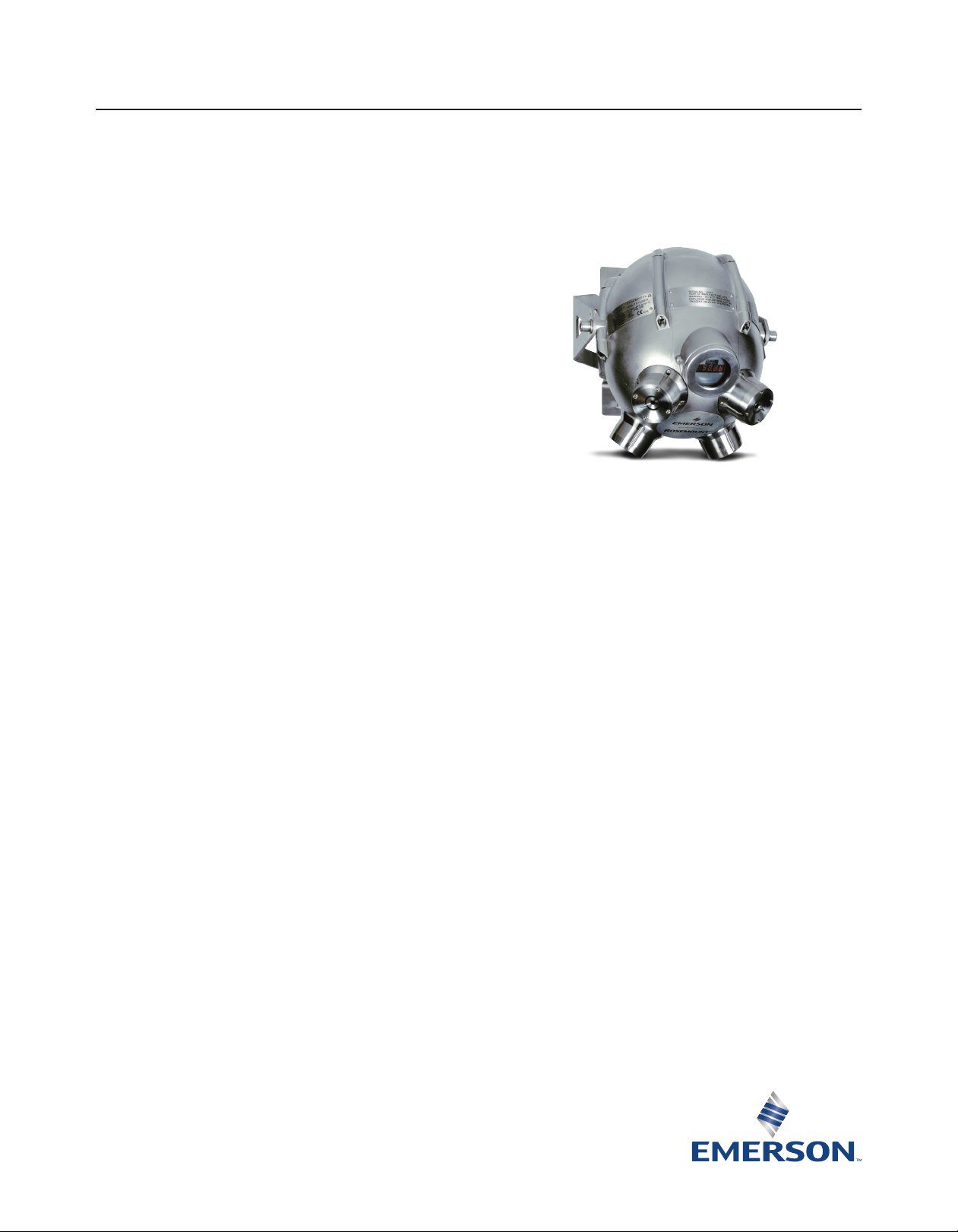
Incus Ultrasonic Gas Leak Detector
Wide Area Coverage for Pressurized Gas Leaks
The Incus is an advanced gas leak detector that
uses four sensitive acoustic sensors to monitor
wide areas for the ultrasound generated from
pressurized gas releases.
Ideally suited for monitoring ventilated outdoor applications,
the Incus has been engineered to withstand extreme
conditions. Detection is unaffected by inclement weather, wind,
leak direction, or gas dilution, with fast speed of response.
Instantaneous response to all gas leaks
(toxic, combustible, or inert).
Operates in extreme temperatures.
Automated electronic self-test offers failsafe operation.
Widest area of coverage through four independent sensors
4–20 mA analog or stepped and HART® communication
protocol.
Certied worldwide for hazardous locations.
Innovative mapping tool helps optimize coverage for a
target risk.
Programmable time delays screen intermittent unwanted
alarm sources.
Four multi-directional sensor heads
Quad sensing heads provide the widest overall detection range
available on the market. The sensing heads are independent
with the detector output being based on the highest ultrasound
measured by any one head. If one or more sensing heads fails,
complete coverage is not lost.
Sensor design - they Just keep working
Each sensor is completely free of moving parts and will not age,
drift, or ever need replacing under normal operating conditions.
The sensors provide maintenance free protection with proven
reliability.
Continuous self-test ensures
instrument health
Electronic self-test checks the detector every 320 ms by
sending an amplitude signal through the sensing circuitry.
The sensor suffers no loss of detection while in test mode in
contrast to those based on diaphragm microphones.
Incus Ultrasonic Gas Leak Detector
Product Data Sheet
July 2017
Field-proven ultrasonic sensor principle
Incus responds to the ultrasound produced by pressurized
gas releases, a technology proven with hundreds of detectors
installed worldwide.
Sealed sensor housing
Piezoceramic sensor heads have no moving parts and can
therefore be completely sealed against moisture, corrosive
atmospheres, and industrial contaminants.
Built for extreme conditions
The Incus is designed to operate at -40 °C to +85 °C (-40 °F to
+185 °F)and may be supplied for monitoring areas of regard
at -55 °C (-67 °F). Corrosion resistant stainless steel housing is
standard, units are ingress rated to IP66/67 or NEMA Type 4X.
Page 2
Incus Ultrasonic Gas Leak Detector
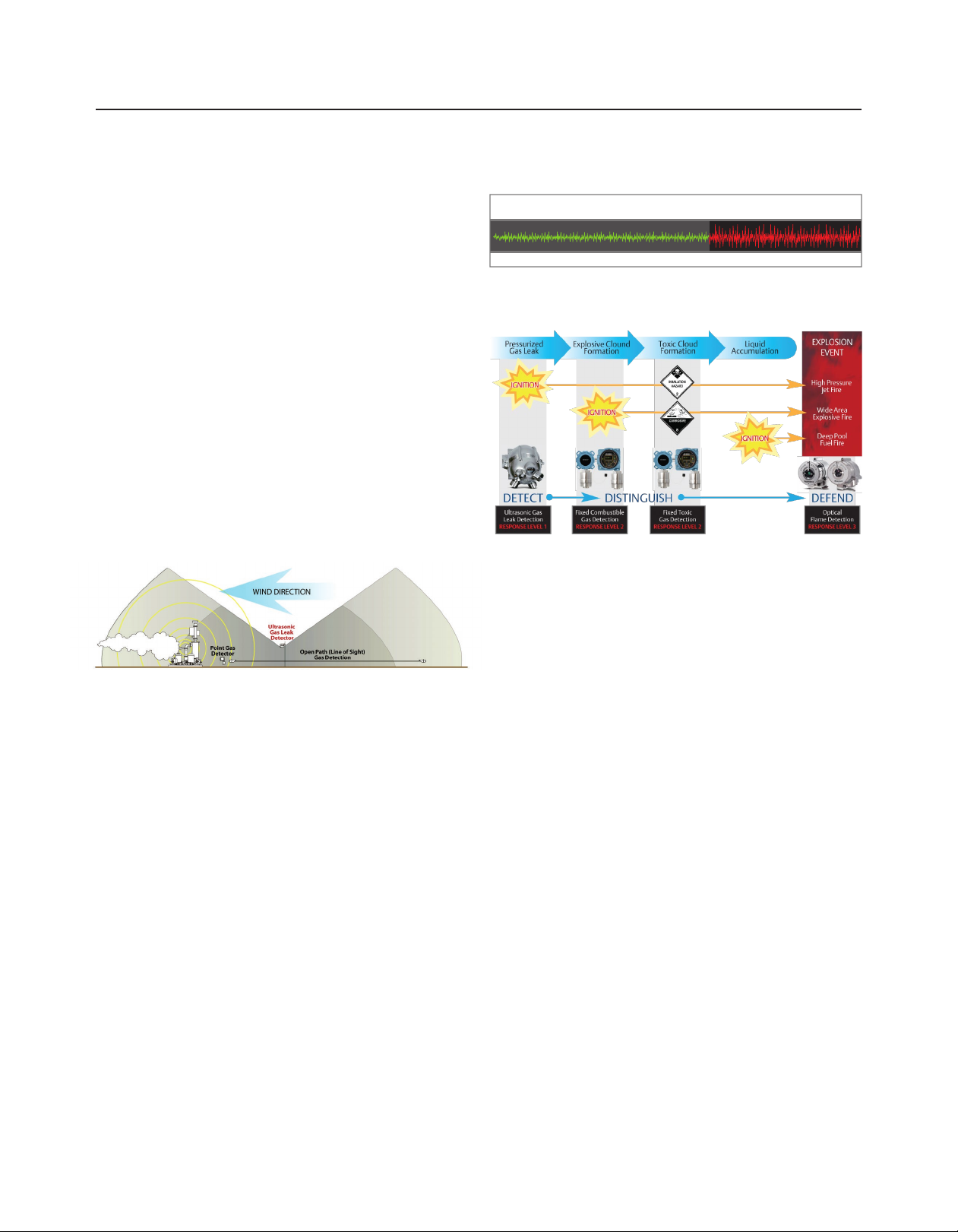
Fixed Toxic
Gas Detection
RESPONSE LEVEL 2
Pressurized Gas Release Response Levels — Detect • Distinguish • Defend
Toxic Cloud
Formation
Liquid
Accumulation
High Pressure
Jet Fire
Wide Area
Explosive Fire
Deep Pool
Fuel Fire
Pressurized
Gas Leak
EXPLOSION
EVENT
IGNITIONIGNITION
IGNITIONIGNITION
IGNITIONIGNITION
Ultrasonic Gas
Leak Detection
RESPONSE LEVEL 1
DETECT DEFENDDISTINGUISH
Fixed Combustible
Gas Detection
RESPONSE LEVEL 2
Optical
Flame Detection
RESPONSE LEVEL 3
Explosive Cloud
Formation
Ultrasonic detection overview
Ultrasonic (acoustic) gas leak detection technology functions
through the constant monitoring of wide areas by advanced
acoustic sensors specially tuned to process ultrasound emitted
from pressurized gas leaks. Ultrasonic gas leak detectors
do not have to wait until a hazardous gas concentration has
accumulated or the gas cloud has made physical contact with
a sensor. In addition, the response is instantaneous for all gas
types (Figure 1).
Simply put, the ultrasonic gas leak detector only triggers an
alarm when inaudible, ultrasound is detected (between 25 and
100 kHz), which is only produced with the release of highly
pressurized gas (Figure 2). This makes for reliable and efcient
detection; since ultrasonic gas leak detectors are immune to
poisoning, it never requires eld calibration, and all intermittent
sources of background ultrasound noises may be ignored by
time delay settings.
Figure 2
Audible Sound 0 KHz to 20 KHz - Turbines, motors, and
compressors generate within this frequency range
Human Hearing Range
Figure 3
July 2017
Incus Detection Range
Ultrasonic Sound 25 KHz to 100 KHz
Beyond Human Hearing Range
Figure 1
The Incus detects gas leaks at the speed of sound while
providing wide area coverage. It is unaffected by inclement
weather, wind, leak direction, and gas dilution or stratication.
When used with Emerson’s point gas and optical ame
detectors, a complete and comprehensive safety system is
ensured (Figure 3).
2 www.Emerson.com/FlameGasDetection
Page 3
July 2017
Incus Ultrasonic Gas Leak Detector
Specifications
Table 1 - Incus Ultrasonic Gas Leak Detector
Incus
Detection frequency range 25 kHz to 100 kHz
Dynamic range 40–120 dB (standard); 58–104 dB or 40–200 dB
Area coverage 2 to 20 meters (7 to 65 feet) radius (leak pressure, size and background level dependent)
Response time Instantaneous (< 1 s - speed of sound)
Programmable alarm delay Congurable alarm delay via one second increments
Operating temperatures -40 °C to +85 °C (-40 °F to +185 °F), option -55 °C (-67 °F), NOT c FM us approved
Operating humidity range 0 to 100 % relative humidity, non-condensing
Self test Continuous electronic check of sensor integrity
Ingress protection Rated IP66/67 & NEMA Type 4X to withstand harsh environments
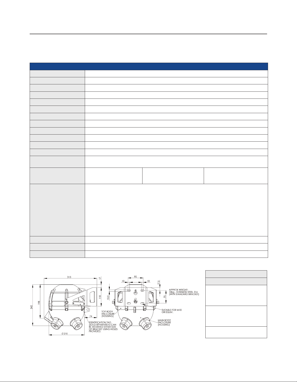
Enclosure material AISI 316 stainless steel
Mounting bracket AISI 316 stainless steel (included)
Weight (with bracket) 18 kg (40 lb)
Conduit entry ½ in. or ¾ in. NPT available as single entry (all listings) or M20/M25 single entry and all dual entry
Output signals Analog [0 mA: zero/low power,
Approvals/classifications IECEx ITS 10.0004X
Input voltage 24 Vdc (15 to 30 Vdc)
Power consumption 6 W - standard operation
Warranty 18 months after shipment or 12 months after installation, whichever comes rst
(all listings EXCEPT FM)
0.5 mA to 4.0 mA: detector
faults, 4–20 mA]
ATEX Ex d ib IIB+H2T4 Gb (Tamb -40 °C to +85 °C); (Tamb -55 °C to +85 °C) option
c FM us CL1 Division 1, GP B, C, D T4
CL1 Zone I, AEx/Ex d ib IIB+H2 T4
EAC RU C-GB.ГБ04.B.00297
KOSHA: 14-KB4BO-0294X
INMETRO UL-BR 15.0063X
ABS: 13-LD1021861
DNV: A-13745
SIL 2 suitable
EMC: EN 50270 2006, EN 61000-6-3 2007, EN 61000-6-2 2005
Two form C relay contacts
[Error/fault, alarm, maintenance]
HART® protocol
Ordering information
Accessories
- GDU-01-TT
Test transmitter: handheld
rechargeable ultrasonic sound
emitter
- GDU-01-MT
Mapping tool: handheld
rechargeable ultrasonic sound
receiver
- GDU-PTV
Performance target verication kit
3www.Emerson.com/FlameGasDetection
Page 4

Incus Ultrasonic Gas Leak Detector
Product certifications
July 2017
Ordinary location certification
As standard, the transmitter has been examined and tested
to determine that the design meets the basic electrical,
mechanical, and re protection requirements by a nationally
recognized test laboratory (NRTL) as accredited by the Federal
Occupational Safety and Health Administration (OSHA).
Installing equipment in North America
The US National Electrical Code (NEC) and the Canadian
Electrical Code (CEC) permit the use of Division marked
equipment in Zones and Zone marked equipment in Divisions.
The markings must be suitable for the area classication, gas,
and temperature class. This information is clearly dened in the
respective codes.
USA
FM Explosionproof (XP)
Certificate: 3043275
Standards: FM Class 3600 – 2011,
FM Class 3615–2006,
FM Class 3810–2005,
ANSI/ISA 60079-0–2009,
ANSI/ISA 60079-1–2009,
ANSI/ISA 60079-11–2011,
ANSI/NEMA 250–1991
Markings: XP CL I, DIV 1, GP B, C, D;
T4 (-40 °C ≤ Ta ≤ +85 °C); CL 1, Zone 1,
AEx d ib IIB+H2 T4 (-40 °C ≤ Ta ≤ +85 °C);
Type 4X
Canada
CSA Explosionproof
Certificate: 3043275
Standards: CSA-C22.2 No. 0.4-04–2009,
CSA-C22.2 No. 0.5-82–2008,
CSA-C22.2 No. 30-86–2012,
CSA-C22.2 No. 94-91 – 2011,
CSA-C22.2 No. 157-92–2012,
CSA-C22.2 No. 1010.1–2004,
CAN/CSA 60079-0–2011,
CAN/CSA 60079-1–2011,
CAN/CSA 60079-11–2011
Markings: XP CL I, DIV 1, GP B, C, D;
T4 (-40 °C ≤ Ta ≤ +85 °C);
CL I, Zone 1, Ex d ib IIB+H2 T4
(-40 °C ≤ Ta ≤ +85 °C); Type 4X
Europe
ATEX Flameproof
Certificate: ITS09ATEX16836X
Standards: EN 60079-0: 2012, EN 60079-1: 2007,
EN 60079-11: 2012
Markings: II 2 G Ex d ib IIB+H2 T4 Gb
(Tamb -55 °C/-40 °C to +85 °C); IP66/67
Special conditions for safe use (X):
1. No modications must be made to the amepaths
of the unit without consultation of the schedule
drawings listed in section 19 of the ATEX
certicate.
2. When the temperature at the cable entry could
exceed 70 °C (158 °F) or 80 °C (176 °F) at the
branching point, suitably rated cable must be
selected based on the T-Class/Tmax.
3. Property Class of the tested stainless steel
fasteners is AA-70, minimum yield strength
450 MPa.
4. Suitably approved cable glands only to be used for
cable entry.
5. Any unused entries must be blanked using suitably
approved blanking plugs.
International
IECEx Flameproof
Certificate: IECEx ITS 10.0004X
Standards: IEC 60079-0:2007-10,
IEC 60079-1:2007-04,
IEC 60079-11:2006
Markings: Ex d ib IIB+H2 T4 Gb
(Tamb -55°C /-40°C to +85°C)
Special conditions for safe use (X):
1. No modications must be made to the amepaths
of the unit without consultation of the drawings
listed in ExTR 10.0027/00.
2. When the temperature at the cable entry could
exceed 70 °C (158 °F) or 80 °C (176 °F) at the
branching point, suitably rated cable must be
selected based on the T-Class/Tmax.
3. Fastener yield strength minimum required to
450 MPa property class AA-70.
4. Suitably approved cable glands only to be used.
5. Any unused entries must be blanked using suitably
approved blanking plugs.
4 www.Emerson.com/FlameGasDetection
Page 5

July 2017
Incus Ultrasonic Gas Leak Detector
Brazil
INMETRO Flameproof
Certicate: UL-BR 15.0063X
Standards: ABNT NBR IEC 60079-0:2008 + Errata1:2011,
ABNT NBR IEC 60079-1:2009 + Errata 1:2011, ABNT
NBR IEC 60079-11:2009
Markings: Ex d ib IIB+H2 T4 Gb (-55°C /-40°C ≤ Ta ≤ +85°C)
Special conditions for safe use (X):
1. No modications must be made to the amepaths
of the unit without consultation of the drawings
listed in ExTR cover sheets.
2. When temperature at the cable entry could exceed
70°C (158 °F) or 80°C (176 °F) at the branching
point, suitably rated cable must be selected based
on the T-Class/T-max.
3. Minimum fastener yield stress required ≥ 450MPa
(property class A*-70.)
4. Suitably approved cable glands only to be used.
5. Any unused entries must be blanked using
suitably approved blanking plugs.
EAC – Belarus, Kazakhstan, Russia
Technical Regulations Customs Union (EAC)
Flameproof
Certificate: RU C-GB.ГБ04.B.00297
Standards: GOST R MEK 60079-0-2011,
GOST IEC 60079-1-2011,
GOST R MEK 60079-11-2010
Markings: 1Ex d ib IIB+H2 T4 Gb X
Special conditions for safe use (X):
1. Unused threads for cable glands must be closed
with type ‘d’ explosion-proof caps veried by
certicate of conformity TR CU 012/2011.
2. Cables must be inserted into the housing with
type ‘d’ explosion-proof cable glands veried by
certicate of conformity TR CU 012/2011.
3. When cable gland temperatures exceed 70 °C
(158 °F), select the appropriate cables based on
the maximum temperature rating specied in
(the certicate) appendix.
Republic of Korea
Republic of Korea Flameproof
Certificate: 14-KB4BO-0294X
Markings: Ex d ib IIB+H2 T4
(Tamb -55 °C/-40 °C to +85 °C)
Additional certifications
American Bureau of Shipping (ABS) Type approval
Certificate: 13-LD1021861-PDA
Intended use: To respond to pressurized gas leaks on
ABS classed vessels, marine, and offshore
installations
ABS rules: Building and classing steel vessels 2013,
1-1-4/7.7, 4-8-3/13.3, 4-9-7/13, 4-9-7/Table 9
Det Norske Veritas (DNV) Type Approval
Certificate: A-13975
Intended use: Det Norske Veritas’ rules for
classication of ships, high speed & light
craft, and Det Norske Veritas’ offshore
standards
Location classes
Temperature D
Humidity B
Vibration A
EMC B
Enclosure C/IP66/67
Manufacturing Address
United Kingdom
Emerson Automation Solutions
Rosemount Measurement Limited
158 Edinburgh Avenue
Slough SL1 4UE, United Kingdom
VAT registered number 864 3831 06
5www.Emerson.com/FlameGasDetection
Page 6

Incus Ultrasonic Gas Leak Detector
Notes
July 2017
6 www.Emerson.com/FlameGasDetection
Page 7

July 2017
Notes
Incus Ultrasonic Gas Leak Detector
7www.Emerson.com/FlameGasDetection
Page 8

Incus Ultrasonic Gas Leak Detector
FGD-PDS-Incus-Ultrasonic-Gas-Leak-Detector
Global Headquarters
Emerson Automation Solutions
6021 Innovation Blvd.
Shakopee, MN 55379, USA
+1 800 999 9307 or +1 952 906 8888
+1 952 949 7001
Safety.CSC@Emerson.com
North America Regional Office
Emerson Automation Solutions
8200 Market Blvd.
Chanhassen, MN 55317, USA
+1 800 999 9307 or +1 952 906 8888
+1 952 949 7001
RFQ-NA.RCCRFQ@Emerson.com
Latin America Regional Office
Emerson Automation Solutions
1300 Concord Terrace, Suite 400
Sunrise, FL 33323, USA
+1 954 846 5030
+1 952846 5121
RFQ.RMD-RCC@Emerson.com
Product Data Sheet
July 2017
Europe Regional Office
Emerson Automation Solutions Europe GmbH
Neuhofstrasse 19a P.O. Box 1046
CH 6340 Baar
Switzerland
+1 954 846 5030
+1 952846 5121
RFQ.RMD-RCC@Emerson.com
Asia Pacific Regional Office
Emerson Automation Solutions Asia Pacific Pte LTD
1 Pandan Crescent
Singapore 128461
+65 6777 8211
+65 6777 0947
Enquiries@AP.Emerson.com
Middle East and Africa Regional Office
Emerson Automation Solutions
Emerson FZE P.O. Box 17033
Jebel Ali Free Zone - South 2
+971 4 8118100
+971 4 88665465
RFQ.RMTMEA@Emerson.com
Analyticexpert.com
Linkedin.com/company/Emerson-Automation-Solutions
Twitter.com/Rosemount_News
Facebook.com/Rosemount
Youtube.com/user/RosemountMeasurement
Google.com/+RosemountMeasurement
The Emerson logo is a trademark and service mark of Emerson Electric
Co.
Rosemount and Rosemount logotype are trademarks of Emerson.
All other marks are the property of their respective owners.
© 2017 Emerson. All rights reserved.
 Loading...