

HART Communication with Flame Detectors and HART Flame Junction Box Interface
Table of contents
 Loading...
Rosemount HART Communication with Flame Detectors and HART Flame Junction Box Interface Manuals & Guides
Page 1
UVS & UVIRS Flame Detectors
Junction Box with HART Interface
Part Number: MAN-0119
HART COMMUNICATION
with
& HART Flame Junction Box interface
FLAME DETECTORS
USER MANUAL
Rev 1 August 2014
Page 2

IMPORTANT INFORMATION
This manual is for informational purposes only. Although every effort has been made to ensure the
correctness of the information, technical inaccuracies may occur and periodic changes may be made
without notice. Net Safety Monitoring Inc., assumes no responsibility for any errors contained within this
manual.
If the products or procedures are used for purposes other than as described in the manual, without
receiving prior confirmation of validity or suitability, Net Safety Monitoring Inc., does not guarantee the
results and assumes no obligation or liability.
No part of this manual may be copied, disseminated or distributed without the express written consent of
Net Safety Monitoring Inc.
Net Safety Monitoring Inc., products are carefully designed and manufactured from high quality
components and can be expected to provide many years of trouble free service. Each product is
thoroughly tested, inspected and calibrated prior to shipment. Failures can occur which are beyond the
control of the manufacturer. Failures can be minimized by adhering to the operating and maintenance
instructions herein. Where the absolute greatest of reliability is required, redundancy should be designed
into the system .
Warranty
Net Safety Monitoring Inc., warrants its sensors against defective parts and workmanship for a period of
24 months from date of purchase; other electronic assemblies for 36 months from date of purchase.
No other warranties or liability, expressed or implied, will be honoured by Net Safety Monitoring Inc.
Contact Net Safety Monitoring Inc or an authorized representative for details.
.
Contact Information
Net Safety Monitoring Inc.
2721 Hopewell Place NE
Calgary, AB
Canada
T1Y 7J7
Telephone: (403) 219-0688 Fax: (403) 219-0694
www.emersonprocess.com/safety
E-mail: safety.csc@emerson.com
© Net Safety Monitoring, Inc. 2014. All rights reserved.
MAN-0119 Rev 1 HART for Flame Page 1 of 28
© Copyright Net Safety Monitoring, Inc. 2014 All Rights Reserved
Page 3

Table of Contents
Important Information ................................................................................................................................... 1
Warranty ....................................................................................................................................................... 1
Contact Information ...................................................................................................................................... 1
SECTION 1: INTRODUCTION .................................................................................................................. 4
1.2 Unpack ................................................................................................................................................ 5
1.3 Mounting ............................................................................................................................................. 5
1.4 Installation Considerations .............................................................................................................. 5
1.5 Wiring ................................................................................................................................................. 5
1.6 Sealing................................................................................................................................................. 6
1.7 HART for Flame Dimensional Drawing ............................................................................................. 6
Figure 1: Dimensional Drawing (Measurements are in Inches and Millimeters) ................................ 6
SECTION 2: Operation ................................................................................................................................ 6
2.1 Current Loop power configurations .................................................................................................... 7
SECTION 3: Configuring the system .......................................................................................................... 8
3.1 Terminals designations for HART and HART/Relay model Junction Box ........................................ 8
Figure 2: HART Flame Junction Box board ......................................................................................... 8
3.1.1 Configuring the relays of HART /Relay Junction Box ................................................................ 9
SECTION 4: HART Connection and Communication .............................................................................. 10
4.1 HART Communicator connection .................................................................................................... 10
Figure 4: Direct HART Communication ............................................................................................ 10
Figure 5: Remote HART Communication via HART Port separation board ..................................... 11
4.2 HART Communication Protocol ...................................................................................................... 12
4.2.1 HART Menu Tree (Structure) .................................................................................................... 13
SECTION 5: Wiring and communication diagrams .................................................................................. 14
5.1 Current Loop power block diagrams ................................................................................................ 14
Figure 6: Current sink and source wiring. ........................................................................................... 14
5.2 Typical Field wiring diagrams .......................................................................................................... 15
5.2.1 IR3S-AH/AHR Non-Isolated current output wiring .................................................................. 15
Figure 7: IR3S-AHR Non Isolated current output wiring diagram .................................................... 15
5.2.2 IR3S-AH/AHR Isolated current output wiring .......................................................................... 16
Figure 8: IR3S-AHR Isolated current output wiring diagram............................................................. 16
5.2.3 UV/IRS-AH/AHR & UVS-AH/AHR Non-Isolated current output wiring ............................... 17
Figure 9: UV/IRS -AHR & UVS-AHR Non- Isolated current output wiring diagram ...................... 17
MAN-0119 Rev 1 HART for Flame Page 2 of 28
© Copyright Net Safety Monitoring, Inc. 2014 All Rights Reserved
Page 4

5.2.4 UV/IRS-AH/AHR & UVS-AH/AHR Isolated current output wiring ........................................ 18
Figure 10: UV/IRS-AHR & UVS-AHR Isolated current output wiring diagram ............................... 18
SECTION 6: Maintenance ......................................................................................................................... 19
6.1 Troubleshoot ..................................................................................................................................... 19
6.2 Spare Parts / Accessories .................................................................................................................. 19
6.3 How to Return Equipment ................................................................................................................ 20
Appendix A: Electrostatic Sensitive Device (ESD) .................................................................................... 21
Appendix B: Resistance Table .................................................................................................................... 22
Appendix C: Specifications and Approvals for HART Flame Junction Box ............................................ 23
MAN-0119 Rev 1 HART for Flame Page 3 of 28
© Copyright Net Safety Monitoring, Inc. 2014 All Rights Reserved
Page 5

SECTION 1: INTRODUCTION
1.1 Description
With the increase in demand for effective, interactive and non-intrusive systems, Net Safety has released
its HART for Flame product providing HART communication with distinct flame detectors. This involves
HART Communication with the Phoenix Triple IR, UV/IR and UV Flame Detectors along with the
Hydrogen Flame Detection line of UV and UV/IR Flame Detectors.
The introduction of HART Communication with flam e detecto rs allows convenient access to the Flame
Detector’s features and provides easy on the spot monitoring. This is important for effective and reliable
maintenance. Access to the HART menu structure and functions of the flame detector is gained by using
the HART Communicator. This may also be done using and any other HART communication devices that
are compatible with the enhanced device descript ion language (EDDL) of Net Safety’s Flame Detectors.
Product components:
This HART for Flame product has two component products; a flame detector with Analog /AnalogDigital output alongside a HART Communication Output inter fa ce . Th is HART Outpu t ci rcuitry is
enclosed in Net Safety’s Explosion Proof Multipurpose Junction Box and allows users to choose AnalogHart or Analog-Hart with Relays outputs. The HART for Flame product is available in Aluminum and
Stainless Steel.
Choice of flame detector:
The model flame detector used with the HART Output interface will depend on users’ choice and nature
of the application. In specific cases users may want to detect hydrogen based fi re s in which case the
UV/IRS-H2-A/AR or the UVS-H2-A/AR flame detector based HART for Flame product would be
suitable. In other cases users may want to use either the IR3S-A/AD, UV/IRS-A/AR or the UVS-A/AR
flame detector based HART for Flame product to detect Hy drocarbon based fires. Refer to available
models offered below.
Available Model HART for Flame Product (this includes HART Flame Junction Box interface):
UV/IRS-AH/AHR, UVS-AH/AHR, UV/IRS-H2-AH/AHR, UVS-H2-AH/AHR
ATEX models: UV/IRS-AH-X/AHR-X, UVS-AH-X/AHR-X, UV/IRS-H2-AH-X/AHR, UVS-H2-AHX/AHR-X
Both CSA/FM and ATEX models are available in Aluminum and Stainless Steel.
Available Model HART Flame Junction Box interface:
JB-MPHF-A (HART output, Aluminum version), JB-MPHF-S (HART output, Stainless Steel version),
JB-MPHFR-A (HART & Relay output, Aluminum version), JB-MPHFR (HART & Relay output,
Stainless Steel version).
System configuration:
After choosing the type of flame detector based on the HART for Flame product, the system should be
configured. This is done via DIP Switch 2 (SW2) located on the HART Flame Junction Box PCB. See
Table 1 when configuring the system.
MAN-0119 Rev 1 HART for Flame Page 4 of 28
© Copyright Net Safety Monitoring, Inc. 2014 All Rights Reserved
Page 6

1.2 Unpack
Carefully remove all components from the packaging. Check components against the enclosed packing
list and inspect all components for obvious damage such as broken or loose parts. If you find any
components missing or damaged, notify the representative or Net Safety Monitoring immediately.
1.3 Mounting
The HART Flame Junction Box has three ¾ inch-14 NPT conduit entries. The flame detector will be
connected to one of these entries. Connection of conduit and cable glands to remaining conduit entries
should be done so by use of appropriate tools. A 6mm Hex Key is required for installing or removing
conduit entry plugs. The junction box has mounting holes for installing directly on a wall or to a pole as
desired. The junction box is supplied with one ATEX stopping plug.
1.4 Installation Considerations
• Point flame detector toward where the flame is expected.
• Ensure an unobstructed view of the area to be monitored.
• Employ more than one flame detector and HART Flame Junction Box to ensure the hazard is fully
covered.
• Mount the flame detector and HART Flame Junction Box a few feet (about 1 metre) below the ceiling
so the flame detector can respond before being blocked by smoke accumulation at the ceiling.
• If dense smoke is likely to accumulate prior to flame (as in an ele ctric al fire ), supp lem ent flame
detector(s) with other protection such as Net Safety Monitoring Airborne Particle Monitor.
• The flame detector should be accessible for cleaning the window and reflector surfaces.
• Tilt the flame detector downward a minimum of 10 to 20
could obscure the detector’s viewing window.
• Securely mount the flame detector and HART Flame Junction Box so as to reduce vibration as much
as possible.
• When located outside, the flame detector’s sensitivity can be reduced by heavy fog, rain and/or ice.
• Consider shortening the time delay settings when smoke is expected to accumulate before or during a
fire. See relevant manual.
• Reduce sensitivity setting if false alarms, related to surrounding activities, occur.
• When installed near or on water (such as an off shore platform), be sure to take into account the low
horizon level when tilting detector downward.
For more on installation considerations on flame detectors refer to specific flame detector manual.
° to reduce dirt and dust accumulation wh ich
1.5 Wiring
Warning Wiring must comply with all applicable regulations relating to the installation of
electrical equipment in a hazardous area and is the responsibility of the installer. Proper shielding and
grounding procedures, for the specific area must be followed. Consult local electrical code and /or
qualified personnel before w iring .
Warning Do not open the HART Flame Junction Box or flame detector in a classified area (Do
not open when an explosive atmosphere may be present). The area should be de-classified prior to
opening.
MAN-0119 Rev 1 HART for Flame Page 5 of 28
© Copyright Net Safety Monitoring, Inc. 2014 All Rights Reserved
Page 7
1.6 Sealing
Warning To fully avoid any environmental exposure (water ingress), the use of seals is
recommended, especially for installations that use high-pressure or steam cleaning devices in proximity to
the HART Flame Junction Box and flame detector.
It is recommended that explosion-proof drains and conduit breathers be used. Changes in temperature and
barometric pressure can cause 'breathing' which allows moist air to enter conduit. Joints are seldom
enough to prevent 'breathing'.
Consult qualified personnel on sealing requirements relating to equipment, application and local
regulations.
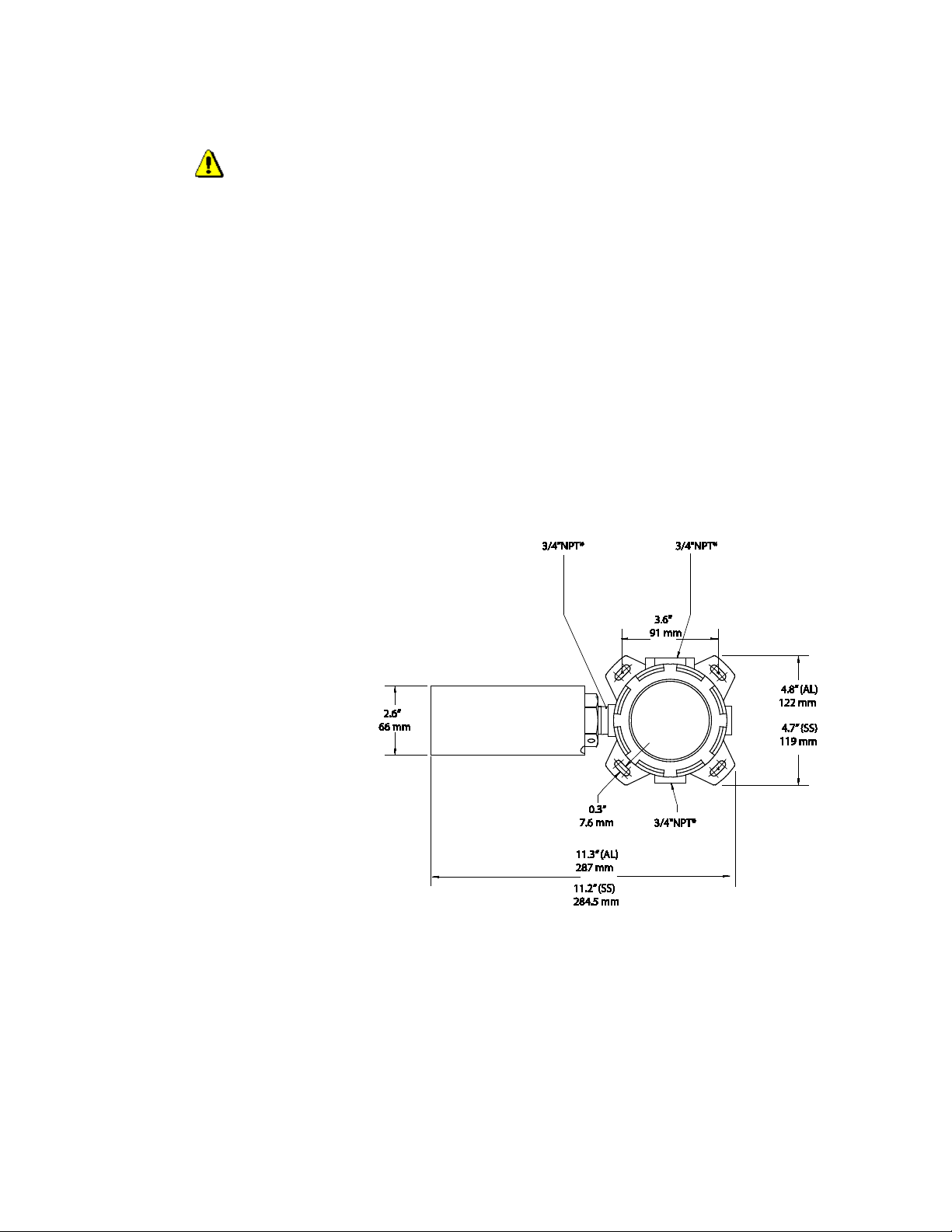
1.7 HART for Flame Dimensional Drawing
The drawing below shows the dimensions of the Aluminum (AL) and Stainless Steel (SS) models of the
flame detector with HART Flame Junction Box enclosure.
Figure 1: Dimensional Drawing (Measurements are in Inches and Millimeters)
Note: CSA/FM model shown
ATEX model has an ATEX locking collar
* M20 & ½” NPT threads also available
SECTION 2: Operation
The model flame detector will determine the model HART for flame unit being used. Specific
combinations of SW2 positions (DIP Switch 2 positions) have been assigned for each available type of
flame detector. Selecting DIP Switch 2 positions correctly will determine the operation of the unit. See
Table 1 and Figure 2 or Figure 3. Once the system has been powered up, confirm operation by referencing
the specific Flame Detector manual. Meter Test Jacks are available on the HART Flame Junction box
PCB to check and monitor the current output (4-20mA). If the HART / Relay model junction box is being
used, note that the relays are dry contacts and are Form C SPDT rated 5 Amperes at 30 VDC/250AC.
MAN-0119 Rev 1 HART for Flame Page 6 of 28
© Copyright Net Safety Monitoring, Inc. 2014 All Rights Reserved
Page 8

If the HART Communicator is to be placed in the current loop, ensure that the HART Jumper (J5) is in
the factory default position (pins jumpered), then place a 250 Ohm resistor in the current loop and connect
the communicator across the resistor. Refer to Figure 2 or Figure 3 along with Current Loop power block
diagrams and / or Typical Field wiring diagrams. If the HART Communicator is to be used with the
HART Port connector for direct or remote communication, see Section 4.
2.1 Current Loop power configurations
The two current loop power configurations available are the Non –Isolated power configuration and the
Isolated power configuration. When using the Non-Isolated power configuration (Non-Isolated current
loop), the Non –ISO / ISO select jumper (JP1) located on the HART Flame Junction box PCB should
remain in its default pos it io n . ‘ISO’ on the power terminal side is not used in this configuration. For the
Isolated power configuration (Isolated current loop), JP1 should be placed over pin 1 and pin 2 and a
separate power supply used to supply +24VDC to ‘ISO’ on the power terminal side. See figure 2 or figure
3 for JP1’s location. Also refer to Current Loop power block diagrams and / or Typical Field wiring
diagrams.
Note: By factory default JP1 (Non –ISO / ISO select jumper) is connected across pin 2 and pin 3 (NonIsolated power configuration). Also by factory default the HART Jumper (J5) is connected (pins are
jumpered).
MAN-0119 Rev 1 HART for Flame Page 7 of 28
© Copyright Net Safety Monitoring, Inc. 2014 All Rights Reserved
Page 9
SECTION 3: Configuring the system
Flame Detector models and DIP Switch 2 (SW2) positions
Flame Detector models
(SW2)Position 1
(SW2)Position 2
IR3S-AD
ON
ON
UV/IRS-A, UVIRS-H2-A
ON
OFF
UVS-A, UVS-H2-A
OFF
ON
IR3S-A
OFF
OFF
Flame Detector Terminal (J4)wiring
Terminal J4
Designation/Function
1
V+ / VDC(+)
2
S_IN / 4-20 mA signal
3
MVI / MVI Test
4
A/communication
5
B/communication
6
GND / VDC(-)
7
ISO / Isolated V+
Power Terminal (J1) wiring
Terminal J1
Designation/Function
6
V+ / Power (+)
5
ISO/ Isolated V+
4
RRS/Alarm Reset
3
MVI / MVI Test
2
S_OUT / 4-20 mA signal
1
GND / Power (-)
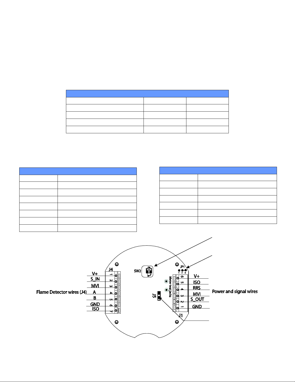
SW2- detector configuration
DIP Switch
JP1- to select Non-Isolated or
configuration.)
J5- HART Jumper (default
When using the specific model flame detectors (IR3S-AD, UV/IRS-A, UV/IRS-H2-A, UVS-A, UVS-H2A, IR3S-A), corresponding SW2 (detector configuration DIP Switch located on HART Flame Jbox PCB)
positions have to be set. The correct combinations of position 1 and position 2 have to be made in order
to have proper operation of the flame detec tor and HART or HART/Relay model Junction Box. See Table
1 and Figure 2 or Figure 3.
Table 1: Configuring HART Flame Junction Box for specific Flame Detector
3.1 Terminals designations for HART and HART/Relay model Junction Box
Table 2: Flame Detector wiring Table 3: Power and output wiring
Figure 2: HART Flame Junction Box board
MAN-0119 Rev 1 HART for Flame Page 8 of 28
© Copyright Net Safety Monitoring, Inc. 2014 All Rights Reserved
Isolated power configurations
(default position - Pin 2 & 3
jumpered for Non-Isolated power
position - pins are jumpered)
Page 10

3.1.1 Configuring the relays of HART /Relay Junction Box
Coil and Latch Status
Fire Relay
Position 1
Position 2
De-Energized/Non-latching
ON
ON
Energized/Non-latching
ON
OFF
De-Energized/ Latching
OFF
ON
Energized/ Latching
OFF
OFF
Relay Terminals (J3)
Alarm Relay
Alarm Relay Contacts
Fault Relay
Fault Relay Contacts
A
NC
Normally Closed
F
NC
Normally Closed
A
C
Common
F
C
Common
A
NO
Normally Open
F
NO
Normally Open
Table 4: DIP Switch Positions (SW1)
SW1- Relay configuration
DIP Switch
Table 5: Relay Contact designations
J5- HART Jumper (default
SW2- detector configuration
DIP Switch
Note: Relays are Form C SPDT rated 5 Amperes at 30 VDC/250AC. Relays are dry contacts.
JP1- to select Non-Isolated or
configuration.)
DIP Switch 1 (SW1) is used to configure the relay coils and set the relay status. See Table 4 below.
Warning Do not open the HART Flame Junction Box or flame detector in a classified area.
Figure 3: HART /Relay Junction Box board
Isolated power configurations
(default position - Pin 2 & 3
jumpered for Non-Isolated power
MAN-0119 Rev 1 HART for Flame Page 9 of 28
© Copyright Net Safety Monitoring, Inc. 2014 All Rights Reserved
position - pins are jumpered)
Page 11

SECTION 4: HART Connection and Communication
Flame Detector
Junction Box with HART interface
HART Communica t or
HART Communica t or
HART Port connector (HPT-001)
4.1 HART Communicator connection
The HART Communicator may be connected to the HART Flame Junction Box via the HART Port
connector. Refer to Figure 4. For remote HART communication, the HART Communicator is connected
to the Junction box interface via a HART Port connector and separation board (JB-MPH-A/S). See Figure
5. Refer to the HART Port connector manual (MAN-0083) and the Net Safety Multi-purpose Junction
Box manual (MAN-0081) during installation.
The HART Communicator may also be placed in the current loop wiring. Refer to Section 4. Place a 250
Ohm load resistor in the 4-20 mA current loop and connect the HART Communicator probes across the
resistor. Do not install a resistor within the HART interface junction box. The total current loop resistance
should be a maximum of 600 Ohms in order to have proper communication with the HART
Communicator.
Figure 4: Direct HART Communication
This drawing is a general representation in connecting the system.
The HART Port connecto r ground
wire should be connected to
intrinsically safe ground.
Probes/wires
Warning
grounded type barrier. The port requires this safe ground to divert the excess energy. The grounding of
the HART Port must meet local safety guidelines
Built within the HART Port connector are intrinsically safe barrier circuits, which are a
.
MAN-0119 Rev 1 HART for Flame Page 10 of 28
© Copyright Net Safety Monitoring, Inc. 2014 All Rights Reserved
Page 12

Figure 5: Remote HART Communication via HART Port separation board
HART Communica t or
HART Communica t or
HART Port connector
Conduit to PLC/DCS/RTU
Junction Box with HART interface
Flame Detector
JB-MPH-A/S
Conduit
To intrinsically safe ground inside
This drawing is a general representation in connecting the system.
the JB-MPH-A/S
Probes/wires
Warning Built within the HART Port connector are intrinsically safe barrier circuits which are a
grounded type barrier. The port requires this safe ground to divert the excess energy. The grounding of
the HART Port must meet local safety guidelines
Important note and Instructions
Note: Refer to The Net Safety Multipurpose Junction Box manual (MAN-0081) and HART Port
connector manual (MAN-0083) when wiring for remote communication.
Instructions: For remote HART communication, connect the HART Jumper (J5) located on the HART
Flame Junction Box terminal board, across the pins (jumper pins). See Figure 2 or Figure 3 for location of
the Jumper.
.
MAN-0119 Rev 1 HART for Flame Page 11 of 28
© Copyright Net Safety Monitoring, Inc. 2014 All Rights Reserved
Page 13

4.2 HART Communication Protocol
The HART protocol incorporates an “Enhanced Device Description Language”, (EDDL) that enables
HART instrument manufacturers to define and document their product in a consistent format. This format
is readable by handheld communicators, PC’s and other process interface devices that support EDDL.
For the Flame Detector- Junction Box Hart interface, handheld HART communicators, PC’s and other
process interface devices must support the latest 16 bits manufacture ID and 16 bits device type. For the
375 model HART Communicator the software version must be at least version 2.0.
Establishing HART Communication with the flame detector and HART Flame Junction Box.
1. Ensure system is wired properly, then power up the unit and ensure no faults are indicated.
2. If the HART Port connector connected to the junction box as an interface, unscrew the HART
Port connector’s protective cap.
3. Connect the HART Communicator non-polarized probes to the 2 non polarized HART Port
connector terminals.
4. If the HART Port connector is not used, ensuring the HART current loop jumper inside the
junction box is in place. Then put the HART communicator probes across a resistor (min. 250
Ohms) within the 4-20 mA loop wiring. The maximum loop resistance of the wiring should be
600 Ohms.
5. Turn on the HART Communicator and proceed to initiate communication. If not familiar with the
communicator, consult the specific HART Communicator manual for operating instructions.
Important Notes:
• Proper analog signal output termination and minimum loop resistance must be completed in
all cases to enable HART communication. Failure to provide proper analog signal output loop
resistance will preclude all HART communication.
• If the HART Communication is not programmed with specific DD or does not support 16 bits
IDs, the JB-MPFH can still connect to the communicator but in the Generic HART
communication mode. In this mode, HART communication with the system will be
established, but the Communicator will not recognize the system (unit). Generic HART
communication will not provide access to the JB-MPHF EDDL menu and important set-up,
diagnostics or operation functions.
If you cannot find Net-Safety or JB-MPHF under Net-Safety on your Communicator, the specific EDDL
is not programmed into communicator. Your HART Communicator will require an EDD L upgrade in
order to access all the JB-MPHF functions.
The HART Communication Foundation, (www.hartcomm.org
Library and programming sites for HCF Approved field communicators. A complete listing of the DD
Library is available for download and provides manufacturer and device type file identification.
See HART Menu Tree (Structure) on next page.
), manages the HCF Approved EDDL
MAN-0119 Rev 1 HART for Flame Page 12 of 28
© Copyright Net Safety Monitoring, Inc. 2014 All Rights Reserved
Page 14

4.2.1 HART Menu Tree (Structure)
Manufacturer Net Safety monitoring inc
MPHF series
Process
Device
PV Value xx mA
Test device
Signal condt
Manufacturer..... Net Safety Monitoring Inc
MPHF series
Long Tag....xx
Tag......xxxxxxxxxxxxxxx
Descriptor....xxxxxxxxxxxxxxx
Message....xxxxxxxxxxxxxxxx
Final asmbly num...xxxxxxxxxxxxxx
Fld dev rev....xxxxxxxxxxxxx
Software rev....xxxxxxxxxxxxx
Root menu
PV LRV..........0.0
PV URV ........20.0
PV rnge..........0.00%
Analog output
Loop current mode
Num reg preams …xx
Num resp preams…xx
PV…….4.00 mA
Loop Test
Date....xx/xx/xx
Time (HHMM)
*MVI*
Reset
Event date......xx/xx/xx
nt time.... HHMM
Most recent......xxxxxx
Status…xxxxxxxx
Start MVI
Flame unit type....xxxxxxxxxxxx (serial number
part number, manufacture date, unit version)
PV .........XX mA
Status.........Normal/xxx
variables
Diag/Service
Detail setup
Date and time
Review
Note: *The MVI function indicated in the above menu tree is not available for the IR3S-A models*. Also
Menus may exist when using communicator but should be ignored if they are not available in this menu
tree.
MAN-0119 Rev 1 HART for Flame Page 13 of 28
© Copyright Net Safety Monitoring, Inc. 2014 All Rights Reserved
PV % rnge 0.00%
PV xx mA
Events log
Flame unit type....IR3S, UVS, UV/IRS
Status.....Normal/xxxxxxx
CLP Modbus output.....good/xxxxxxx
DIP switch settings.....good/xxxxxxx
Output condt
Device information
Model ..... JB-
Dev ID xxxxxx
Tag xxxxxxxxxxx
Long Tag xxxxxxxxxxxxxx
Descriptor xxxxxxxxxxxxxx
Message xxxxxxxxxxxxxx
Date xx/xx/xx
Final asmbly num xxxxxxx
Universal rev 7
Fld dev rev xx
Software rev xx
Poll addr xx
Loop current mode Disabled/Enabled
Num reg preams xx
Num resp preams xx
Loop Test
HART output
Model......JB-
Device ID.....xx
Date.....xx/xx/xx
Universal rev....xxxxxxxxxxxxxx
Flame Unit Information
Stop MVI
Eve
Event type....xxxxxxxx
Next log......xxxxxxxxx
Previous log..... xxxxxx
Poll addr……xx
Page 15

SECTION 5: Wiring and communication diagrams
5.1 Current Loop power block diagrams
Warning DIP Switch 1 position 4 on the IR3S-AD Flame Detector electronics, should remain in
the factory default position (OFF); do not change this position. Also do not change the position of the
current output jumper on the IR3S-A/AD electronics; the jumper should remain in the factory default
position (INT position). See IR3S Flame Detector manual.
Note the position of the Non-ISO / ISO select jumper (JP1) on the HART Flame Junction Box
interface for each configuration.
Figure 6: Current sink and source wiring.
MAN-0119 Rev 1 HART for Flame Page 14 of 28
© Copyright Net Safety Monitoring, Inc. 2014 All Rights Reserved
Page 16
5.2 Typical Field wiring diagrams
The following drawings are typical ways in wiring each flame detector and the HART/Relay Junction
Box using general wiring requirements. Consult qualified personnel on specific wiring requirements. Note
that alarms are wired in parallel in the examples shown.
Warning DIP Switch 1 position 4 on the IR3S-AD Flame Detector electronics, should remain in
the factory default position (OFF); do not change this position. Also do not change the position of the
current output jumper on the IR3S-A/AD electronics; the jumper should remain in the factory default
position (INT position). See IR3S Flame Detector manual.
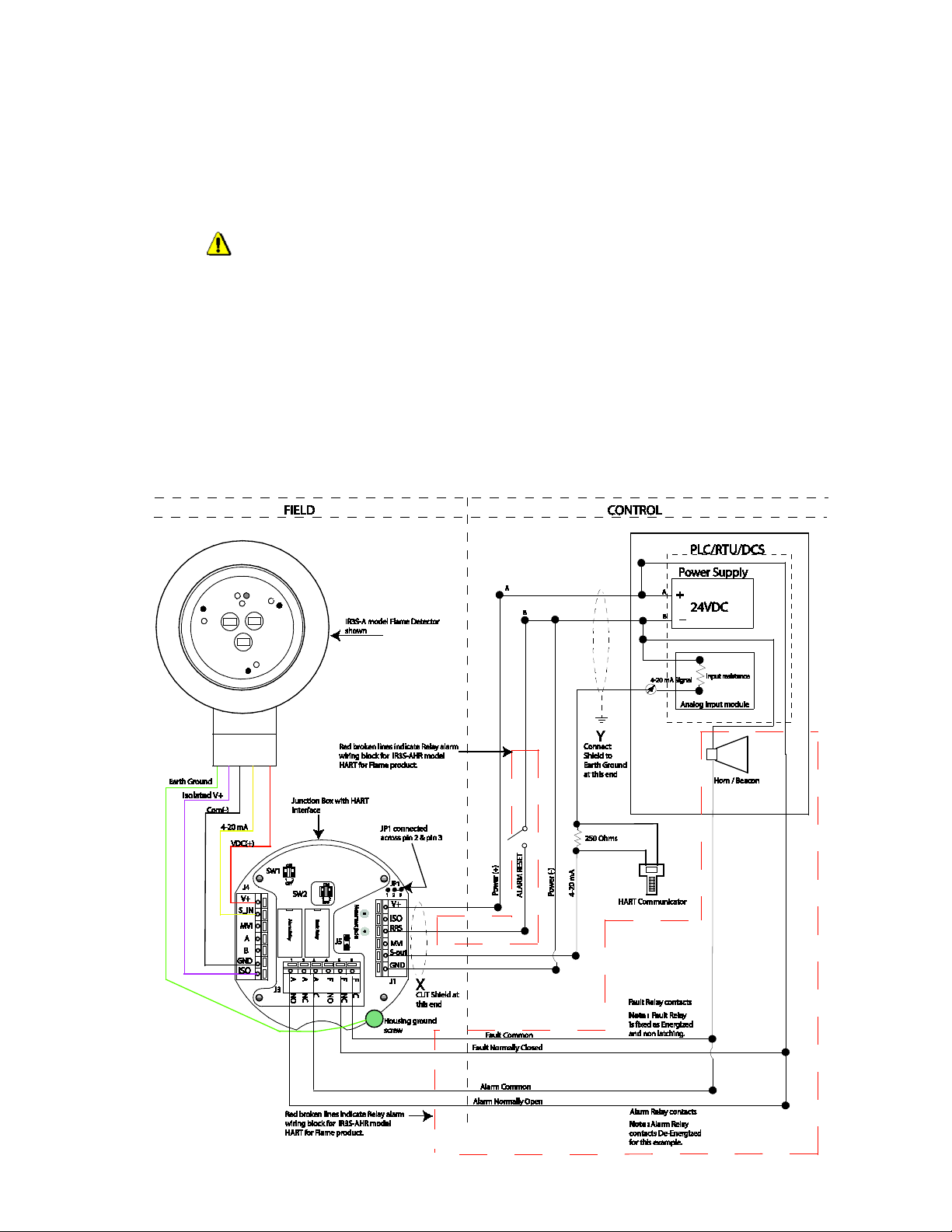
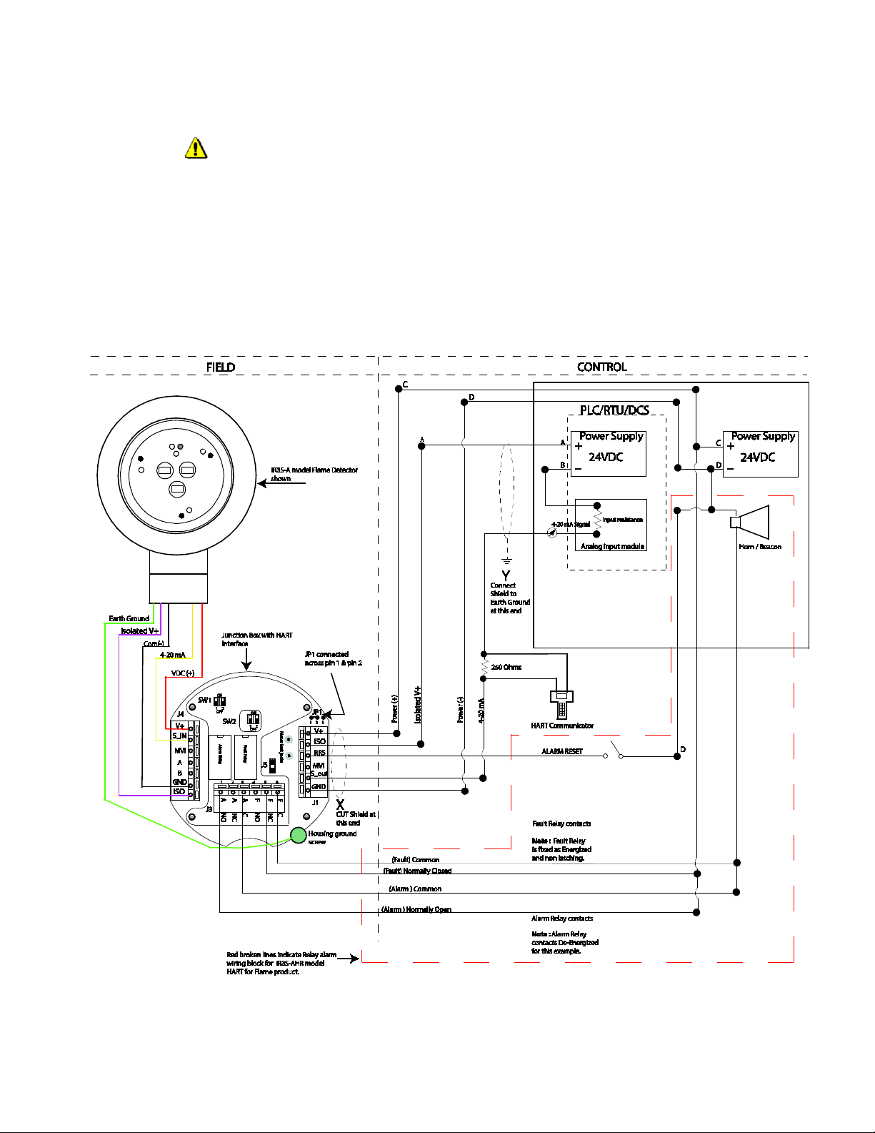
5.2.1 IR3S-AH/AHR Non-Isolated current output wiring
Wiring of the IR3S-AH and IR3S-AHR model HART for flame products is similar , except for the re lay
alarm wiring shown in broken red lines. Ignore this block if the IR3S-AH is being wired.
Note the position of the Non-ISO / ISO select jumper (JP1) on the HART Flame Junction Box
interface.
Figure 7: IR3S-AHR Non Isolated current output wiring diagram
MAN-0119 Rev 1 HART for Flame Page 15 of 28
© Copyright Net Safety Monitoring, Inc. 2014 All Rights Reserved
Page 17
5.2.2 IR3S-AH/AHR Isolated current output wiring
Warning DIP Switch 1 position 4 on the IR3S-AD Flame Detector electronics, should remain in
the factory default position (OFF); do not change this position. Also do not change the position of the
current output jumper on the IR3S-A/AD electronics; the jumper should remain in the factory default
position (INT position). See IR3S Flame Detector manual.
Wiring of the IR3S-AH and IR3S-AHR model Hart for flame products is similar, except for the relay
alarm wiring shown in broken red lines. Ignore this block if the IR3S-AH model is being wired.
Note the position of the Non-ISO / ISO select jumper (JP1) on the HART Flame Junction Box
interface.
Figure 8: IR3S-AHR Isolated current output wiring diagram
MAN-0119 Rev 1 HART for Flame Page 16 of 28
© Copyright Net Safety Monitoring, Inc. 2014 All Rights Reserved
Page 18
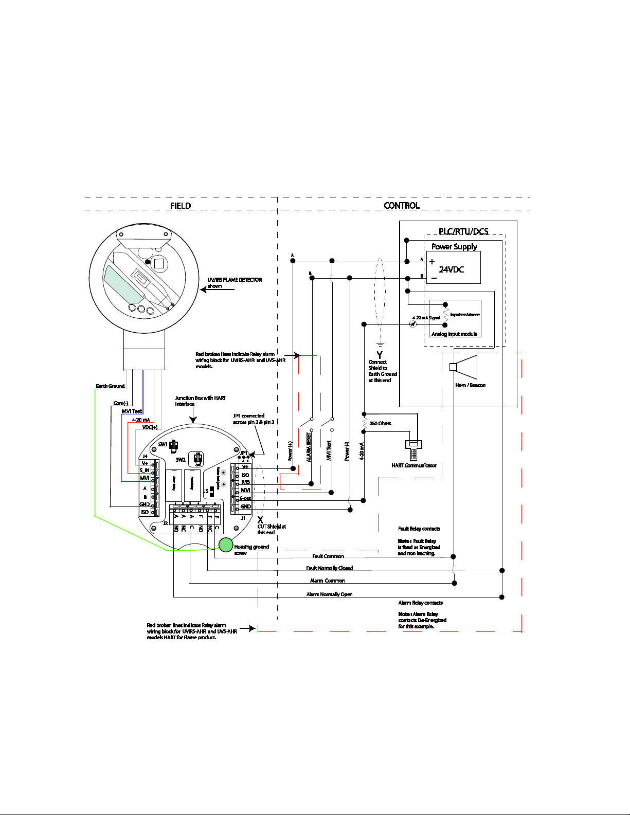
5.2.3 UV/IRS-AH/AHR & UVS-AH/AHR Non-Isolated current output wiring
Wiring of the UV/IRS-AH/AHR & UVS-AH/AHR HART for flame products is similar, except for the
relay alarm wiring shown in broken red lines. Ignore this block if the UV/IRS-AH or UVS-AH model is
being wired.
Note the position of the Non-ISO / ISO select jumper (JP1) on the HART Flame Junction Box
interface.
Figure 9: UV/IRS -AHR & UVS-AHR Non- Isolated current output wiring diagram
MAN-0119 Rev 1 HART for Flame Page 17 of 28
© Copyright Net Safety Monitoring, Inc. 2014 All Rights Reserved
Page 19

5.2.4 UV/IRS-AH/AHR & UVS-AH/AHR Isolated current output wiring
Wiring of the UV/IRS-AH/AHR & UVS-AH/AHR HART for flame products is similar, except for the
relay alarm wiring shown in broken red lines. Ignore this block if the UV/IRS-AH or UVS-AH model is
being wired.
Note the position of the Non-ISO / ISO select jumper (JP1) on the HART Flame Junction Box
interface.
Figure 10: UV/IRS-AHR & UVS-AHR Isolated current output wiring diagram
MAN-0119 Rev 1 HART for Flame Page 18 of 28
© Copyright Net Safety Monitoring, Inc. 2014 All Rights Reserved
Page 20

SECTION 6: Maintenance
Each type of flame detector performs an automatic visual integrity test on the optics to ensure there is no
obstruction on or near the detectors lens. Though this test is done, it is important to perform routine
maintenance checks and cleaning of the window/lens. It is recommended that cleaning be done with Net
Safety cleaning products. In addition to established maintenance rou tines, perform response tests on the
detector by using the appropriate Net Safety Test Lamp to simulate fire con d it ions. Refer to specific
flame detector and test lamp manuals when performing the above checks.
6.1 Troubleshoot
If a problem should develop, Check DIP Switch 2 (SW2) positions to confirm correct configuration, ref er
to specific flame detector manual and ensure all wiring is correctly done. If the problem remains refer to
“How to Return Equipment”.Net Safety Flame Detectors and HART Flame Junction boxes are not
designed to be repaired in the field.
Repairs to faulty or damaged equipment should only be performed at
the factory; otherwise warranty on the product will be voided.
6.2 Spare Parts / Accessories
Table 6: Available Spare Parts
Description Net Safety Part Number
Analog model IR3S Electronics IR3S-EMOD-A
Analog/Digital model IR3S Electronics IR3S-EMOD-AD
Analog model UV./IRS Electronics UV/IRS-EMOD-A
Analog model UVS-A Electronics UVS-EMOD-A
Analog model UV/IRS-H2-A Electronics UV/IRS-H2-EMOD-A
Analog model UVS-H2-A Electronics UVS-H2-EMOD-A
HART PCB for HART Flame Junction Box KIT-0505
Relay PCB for HART Flame Junction Box KIT-0506
MAN-0119 Rev 1 HART for Flame Page 19 of 28
© Copyright Net Safety Monitoring, Inc. 2014 All Rights Reserved
Page 21

6.3 How to Return Equipment
A Material Return Authorization number is required in order to return equipment. Please contact Net
Safety Monitoring at (403) 219-0688, before ret urning equip ment or consul t our Service Department t o
possibly avoid returning equipment.
If you are required to return equipment, include the following information:
1. A Material Return Authorization number (provided over the phone to you by Net Safety).
2. A detailed description of the problem. The more specific you are regarding the problem, the
quicker our Service Department can determine and correct the problem.
3. A company name, contact name and telephone number.
4. A purchase order, from your company, authorizing repairs or request for quote.
5. Ship all equipment, prepaid to: Net Safety Monitoring Inc.,
2721 Hopewell Place NE,
Calgary, Alberta, Canada, T1Y 7J7
6. Mark all packages: RETURN for REPAIR.
7. Waybills, for shipment outside Canada, must state: Equipment being returned for repair
All charges to be billed to the sender
Ensure a duplicate copy of the packing slip is enclosed inside the box indicating item 1 – 4 along with the
courier and account number for returning the goods.
Pack items to protect them from damage and use anti-static bags or aluminum-backed cardboard as
protection from electro-static discharge.
ALL equipment must be shipped prepaid. Collect shipments will not be accepted.
MAN-0119 Rev 1 HART for Flame Page 20 of 28
© Copyright Net Safety Monitoring, Inc. 2014 All Rights Reserved
Page 22

Appendix A: Electrostatic Sensitive Device (ESD)
Definition: Electrostatic discharge (ESD) is the transfer, between bodies, of an electrostatic charge
caused by direct contact or induced by an electrostatic field.
The most common cause of ESD is physical contact. Touching an object can cause a discharge of
electrostatic energy—ESD! If the charge is sufficient and occurs near electronic components, it can
damage or destroy those components. In some cases, damage is instantaneous and an immediate
malfunction occurs. However , symptoms are not always immediate—performance may be marginal or
seemingly normal for an indefinite period of time, followed by a sudden failure.
To eliminate potential ESD damage, review the following guidelines:
• Handle boards by metal shields—taking care not to touch electronic components.
• Wear grounded wrist or foot straps, ESD shoes or heel grounders to dissipate unwanted static
energy.
• Prior to handling boards, dispel any charge in your body or equipment.
• Ensure all components are transported and stored in static safe packaging
• When returning boards, carefully package in the original carton and static protective wrapping
• Ensure ALL personnel are educated and trained in ESD Control Procedures
In general, exercise accepted and proven precautions normally observed when handling electrostatic
sensitive devices. A warning label is placed on the packaging, identifying product using electrostatic
sensitive semiconductor devices.
MAN-0119 Rev 1 HART for Flame Page 21 of 28
© Copyright Net Safety Monitoring, Inc. 2014 All Rights Reserved
Page 23

Appendix B: Resistance Table
Distance
(Feet)
Table 7: Wire resistance with distance and gauge
AWG #20 AWG #18 AWG #16 AWG #14 AWG #12 AWG #10 AWG #8
100
200
300
400
500
600
700
800
900
1000
1250
1500
1750
2000
2250
2500
1.02 0.64 0.40 0.25 0.16 0.10 0.06
2.03 1.28 0.80 0.51 0.32 0.20 0.13
3.05 1.92 1.20 0.76 0.48 0.30 0.19
4.06 2.55 1.61 1.01 0.64 0.40 0.25
5.08 3.20 2.01 1.26 0.79 0.50 0.31
6.09 3.83 2.41 1.52 0.95 0.60 0.38
7.11 4.47 2.81 1.77 1.11 0.70 0.44
8.12 5.11 3.21 2.02 1.27 0.80 0.50
9.14 5.75 3.61 2.27 1.43 0.90 0.57
10.20 6.39 4.02 2.53 1.59 1.09 0.63
12.70 7.99 5.03 3.16 1.99 1.25 0.79
15.20 9.58 6.02 3.79 2.38 1.50 0.94
17.80 11.20 7.03 4.42 2.78 1.75 1.10
20.30 12.80 8.03 5.05 3.18 2.00 1.26
22.80 14.40 9.03 5.68 3.57 2.25 1.41
25.40 16.00 10.00 6.31 3.97 2.50 1.57
3000
3500
4000
4500
5000
5500
6000
6500
7000
7500
8000
9000
10000
Resistance shown is one way. Thi s fi gure sho uld be doubled when determining closed loop resistance.
30.50 19.20 12.00 7.58 4.76 3.00 1.88
35.50 22.40 14.10 8.84 5.56 3.50 2.21
40.60 25.50 16.10 10.00 6.35 4.00 2.51
45.70 28.70 18.10 11.40 7.15 4.50 2.82
50.10 32.00 20.10 12.60 7.94 5.00 3.14
55.80 35.10 22.10 13.91 8.73 5.50 3.46
61.00 38.30 24.10 15.20 9.53 6.00 3.77
66.00 41.50 26.10 16.40 10.30 6.50 4.08
71.10 44.70 28.10 17.70 11.10 7.00 4.40
76.10 47.90 30.10 19.00 12.00 7.49 4.71
81.20 51.10 23.10 20.20 12.70 7.99 5.03
91.40 57.50 36.10 22.70 14.30 8.99 5.65
102.00 63.90 40.20 25.30 15.90 9.99 6.28
MAN-0119 Rev 1 HART for Flame Page 22 of 28
© Copyright Net Safety Monitoring, Inc. 2014 All Rights Reserved
Page 24
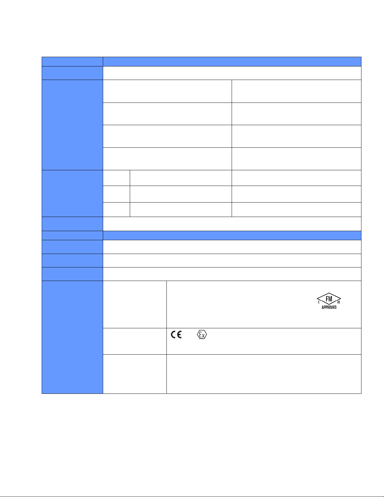
Appendix C: Specifications and Approvals for HART Flame Junction Box
Specification
HART for Flame Junction Box Electronics
Specification
Junction Box
FM07ATEX0044
Electrical Rating
Power Consumption
Power Consumption
with Flame Detector
Temperature
Metallurgy
IR3S
UV/IRS
UVS
Operation Voltage: 18 to 32 VDC
HART MODEL
At 18VDC: Nominal 33mA/0.6W
Max 67mA/1.2W
At 24 VDC: Nominal 26mA/0.6W
Max 58mA/1.4W
At 32 VDC: Nominal 22mA/0.6W
Max 53mA/1.7W
2.84W @ 24Vdc 3.44W @ 24Vdc
4.16W @ 24Vdc 4.76W @ 24Vdc
4.16W @ 24Vdc 4.76W @ 24Vdc
-40°C to +75°C (electronics)
HART/RELAY MODEL
(Relays are rated 5A at 30VDC/250AC. Relays are
Form C SPDT, dry contacts)
At 18VDC: Nominal 53mA/0.95W
Max 105mA/1.9W
At 24VDC: Nominal 41mA/0.98W
Max 83mA/2.0W
At 32VDC: Nominal 33mA/1.1W
Max 68.8mA/2.2W
Aluminum or 316 SS
Weight
NEMA / IP Rating
North American
Approvals
ATEX
IECEx
Aluminum: 0.8 Kg / 2.0 lbs (316 SS 1.6 Kg / 3.5lbs)
NEMA 4X, IP67
Class 1 Division 1 Groups BCD, T5
Class 1 Zone 1 Ex d IIB +H2 T5 (Canada)
Class 1 Zone 1 AEx d IIB +H2 T5 (USA)
-55°C ≤ Ta + 85°C
NEMA Type 4X/IP67
0575 II 2G Ex d IIB+H2 T5 Gb
-55°C to +85°C, IP67
EX d IIB+H2 T5
-55°C ≤ Ta + 85°C IP 67
IEC 60079-0:2011/IEC 60079-1:2007
IECEx FMG 14.0009X
MAN-0119 Rev 1 HART for Flame Page 23 of 28
© Copyright Net Safety Monitoring, Inc. 2014 All Rights Reserved
Page 25

Notes:
MAN-0119 Rev 1 HART for Flame Page 24 of 28
© Copyright Net Safety Monitoring, Inc. 2014 All Rights Reserved
Page 26

Notes:
MAN-0119 Rev 1 HART for Flame Page 25 of 28
© Copyright Net Safety Monitoring, Inc. 2014 All Rights Reserved
Page 27

Notes:
MAN-0119 Rev 1 HART for Flame Page 26 of 28
© Copyright Net Safety Monitoring, Inc. 2014 All Rights Reserved
Page 28

Net Safety Monitoring Inc.
2721 Hopewell Place NE, Calgary, AB Canada T1Y 7J7
1-866-FIREGAS (347-3427) | ph. (403) 219-0688 | fx. (403) 219-0694
www.emersonprocess.com/safety | Email: safety.csc@emerson.com
Loading...