

Guided Wave Radar Transmitters in Upstream Applications-Best Practices User Guide
Table of contents
 Loading...
Rosemount Guided Wave Radar Transmitters in Upstream Applications-Best Practices User Guide Manual Supplement

Reference Manual
00809-0600-4811, Rev AA
February 2009
Rosemount Guided Wave Radar
Transmitters in Upstream Applications
Best Practices User Guide
www.rosemount.com

Reference Manual
00809-0600-4811, Rev AA
February 2009
Rosemount Radar Level Transmitters
Rosemount Guided Wave Radar
Transmitters in Upstream
Applications
Best Practices Users Guide
The products described in this document are NOT designed for nuclear-qualified
applications.
Using non-nuclear qualified products in applications that require nuclear-qualified hardware
or products may cause inaccurate readings.
For information on Rosemount nuclear-qualified products, contact your local Rosemount
Sales Representative.
This product is designed to meet FCC and R&TTE requirements for a non-intentional
radiator. It does not require any licensing whatsoever and has no tank restrictions
associated with telecommunications issues.
This device complies with part 15 of the FCC rules. Operation is subject to the following two
conditions: (1) This device may not cause harmful interference, and (2) this device must
accept any interference received, including interference that may cause undesired
operation.
Rosemount 3300 Series Guided Wave Radar Level and Interface Transmitters may be protected by one or
more of the following U.S. Patent Nos. 5,955,684; 6,148,681; 6,198,424; 6,373,261 and other patents issued or
pending in the U.S. and other countries. May depend on model.
Rosemount 5300 Series High Performance Guided Wave Radar Transmitters may be protected by one or more
of the following U.S: Patent Nos. 6,148,681; 5,955,684; 6,295,018; 6,198,424; 6,972,712; 6,842,139; 6,700,530
and other patents issued or pending in the U.S. and other countries. May depend on model.
Cover Photo: cover_combined 2.jpg
www.rosemount.com


Reference Manual
00809-0600-4811, Rev AA
February 2009
Rosemount Radar Level Transmitters
Table of Contents
SECTION 1
Introduction
SECTION 2
Installation
Considerations
SECTION 3
Upstream Applications
Introduction . . . . . . . . . . . . . . . . . . . . . . . . . . . . . . . . . . . . . . . . . . . . . 1-1
System Integration. . . . . . . . . . . . . . . . . . . . . . . . . . . . . . . . . . . . . . . . 1-2
Safety messages . . . . . . . . . . . . . . . . . . . . . . . . . . . . . . . . . . . . . . . . . 2-1
Introduction . . . . . . . . . . . . . . . . . . . . . . . . . . . . . . . . . . . . . . . . . . . . . 2-2
Mechanical Installation . . . . . . . . . . . . . . . . . . . . . . . . . . . . . . . . . . . . 2-2
Recommended Mounting Position . . . . . . . . . . . . . . . . . . . . . . . . . 2-2
Transition Zones. . . . . . . . . . . . . . . . . . . . . . . . . . . . . . . . . . . . . . . 2-5
Process Connections . . . . . . . . . . . . . . . . . . . . . . . . . . . . . . . . . . . 2-7
Electrical Installation . . . . . . . . . . . . . . . . . . . . . . . . . . . . . . . . . . . . . 2-12
Rosemount 3300 Series: HART Version . . . . . . . . . . . . . . . . . . . 2-12
Rosemount 3300 Series: Modbus Version . . . . . . . . . . . . . . . . . . 2-13
PC Communication with MA(+) MB(-) . . . . . . . . . . . . . . . . . . . . . 2-14
Cathodic Protection . . . . . . . . . . . . . . . . . . . . . . . . . . . . . . . . . . . 2-15
Rosemount 5300 Series: HART Version . . . . . . . . . . . . . . . . . . . 2-16
Rosemount 5300 Series: Foundation™ fieldbus Version. . . . . . . 2-18
Specific Applications . . . . . . . . . . . . . . . . . . . . . . . . . . . . . . . . . . . . . . 3-1
Separators . . . . . . . . . . . . . . . . . . . . . . . . . . . . . . . . . . . . . . . . . . . . . . 3-2
Horizontal separator (bullet tank) . . . . . . . . . . . . . . . . . . . . . . . . . . 3-2
Vertical separator (vertical cylinder tank) . . . . . . . . . . . . . . . . . . . . 3-3
Output measurement at different interface levels. . . . . . . . . . . . . . 3-4
Production/Slop Tanks. . . . . . . . . . . . . . . . . . . . . . . . . . . . . . . . . . . . . 3-7
Vertical cylinder . . . . . . . . . . . . . . . . . . . . . . . . . . . . . . . . . . . . . . . 3-7
Slop tanks . . . . . . . . . . . . . . . . . . . . . . . . . . . . . . . . . . . . . . . . . . . . . . 3-9
Underground or open pit. . . . . . . . . . . . . . . . . . . . . . . . . . . . . . . . . 3-9
SECTION 4
Commissioning
SECTION 5
Troubleshooting
www.rosemount.com
Safety messages . . . . . . . . . . . . . . . . . . . . . . . . . . . . . . . . . . . . . . . . . 4-1
Introduction . . . . . . . . . . . . . . . . . . . . . . . . . . . . . . . . . . . . . . . . . . . . . 4-2
Commissioning . . . . . . . . . . . . . . . . . . . . . . . . . . . . . . . . . . . . . . . . . . 4-2
Trim Near Zone . . . . . . . . . . . . . . . . . . . . . . . . . . . . . . . . . . . . . . . 4-2
Store Backup and Verification Files . . . . . . . . . . . . . . . . . . . . . . . . 4-4
Plotting the Measurement Signal. . . . . . . . . . . . . . . . . . . . . . . . . . . . . 4-5
Plotting the Measurement Signal for the Rosemount 3300 Series. 4-5
Plotting the Measurement Signal for the Rosemount 5300 Series. 4-6
Differences Between Plots in RRM and RCT . . . . . . . . . . . . . . . . . 4-9
Safety messages . . . . . . . . . . . . . . . . . . . . . . . . . . . . . . . . . . . . . . . . . 5-2
Rosemount 3300 Threshold Settings . . . . . . . . . . . . . . . . . . . . . . . . . 5-3
Case 1 - Level measurements . . . . . . . . . . . . . . . . . . . . . . . . . . . . 5-3
Case 2 - Level & Interface measurements . . . . . . . . . . . . . . . . . . . 5-4
Disturbances From Nozzle . . . . . . . . . . . . . . . . . . . . . . . . . . . . . . . . . 5-5
Upper Null Zone adjustment. . . . . . . . . . . . . . . . . . . . . . . . . . . . . . 5-5

Rosemount Radar Level Transmitters
Nozzle influence . . . . . . . . . . . . . . . . . . . . . . . . . . . . . . . . . . . . . . . 5-6
Near Zone Threshold . . . . . . . . . . . . . . . . . . . . . . . . . . . . . . . . . . . 5-7
Rosemount 5300 Threshold Settings . . . . . . . . . . . . . . . . . . . . . . . . 5-10
Device status . . . . . . . . . . . . . . . . . . . . . . . . . . . . . . . . . . . . . . . . . . . 5-12
Device Status: Rosemount 3300 Series. . . . . . . . . . . . . . . . . . . . 5-12
Device Status: Rosemount 5300 Series. . . . . . . . . . . . . . . . . . . . 5-13
Reference Manual
00809-0600-4811, Rev AA
February 2009
SECTION 6
Verification Procedure
APPENDIX A
Model Code Information
Introduction . . . . . . . . . . . . . . . . . . . . . . . . . . . . . . . . . . . . . . . . . . . . . 6-1
Verification Procedure . . . . . . . . . . . . . . . . . . . . . . . . . . . . . . . . . . . . . 6-2
Self Test . . . . . . . . . . . . . . . . . . . . . . . . . . . . . . . . . . . . . . . . . . . . . 6-2
Rosemount 3300 Plot Verification . . . . . . . . . . . . . . . . . . . . . . . . . 6-3
Rosemount 5300 Plot Verification . . . . . . . . . . . . . . . . . . . . . . . . . 6-4
Diagnostics . . . . . . . . . . . . . . . . . . . . . . . . . . . . . . . . . . . . . . . . . . . . . 6-5
Model Code 3302 and 5302, Level and Interface in Liquids . . . . . . . . A-2
Model Code Example - Rosemount 3300 Series . . . . . . . . . . . . . A-5
Model Code Example - Rosemount 5300 Series . . . . . . . . . . . . . . A-5
TOC-2

Reference Manual
00809-0600-4811, Rev AA
February 2009
Rosemount Radar Level Transmitters
Section 1 Introduction
Introduction . . . . . . . . . . . . . . . . . . . . . . . . . . . . . . . . . . . . . page 1-1
System Integration . . . . . . . . . . . . . . . . . . . . . . . . . . . . . . . page 1-2
INTRODUCTION This document describes some of the best practices learned during the
installation of thousands of Rosemount Guided Wave Radar level transmitters
in upstream oil and gas applications. However, it is not a complete set of
instructions; for more detailed information, refer to the respective product
manual:
• Rosemount 5300 Series Reference Manual
(Document No. 00809-0100-4530)
• Rosemount 3300 Series Reference Manual
(Document No. 00809-0100-4811)
The Rosemount 3300 Series and 5300 Series Guided Wave Radar
transmitters are Time Domain Reflectometry Pulsed Radar level instruments.
They are utilized in the Oil and Gas industry for the measurement of
hydrocarbons and water in production and separator tanks. Both the
Rosemount 3300 and 5300 Series have the ability to measure overall level as
well as interface level in the vessels. They can be installed in several different
configurations including flanges, threaded, and side-mounted connections.
The Rosemount 3300 can transmit measurement values and diagnostics with
the 4-20 mA HART
protocols. The Rosemount 5300 is a high performance transmitter and can
transmit measurement values and diagnostics with the 4-20 mA HART and
F
OUNDATION™ fieldbus communication protocols.
This document describes which series, models, and probes to use on the
various applications within upstream Oil and Gas fields, and therefore serves
as a selection guideline specific to these applications and needs. Local
restrictions, regulations, or best practices may also apply and should be taken
into consideration.
®
and RS-485 Modicon RTU Modbus communication
www.rosemount.com
Rosemount Radar Level Transmitters
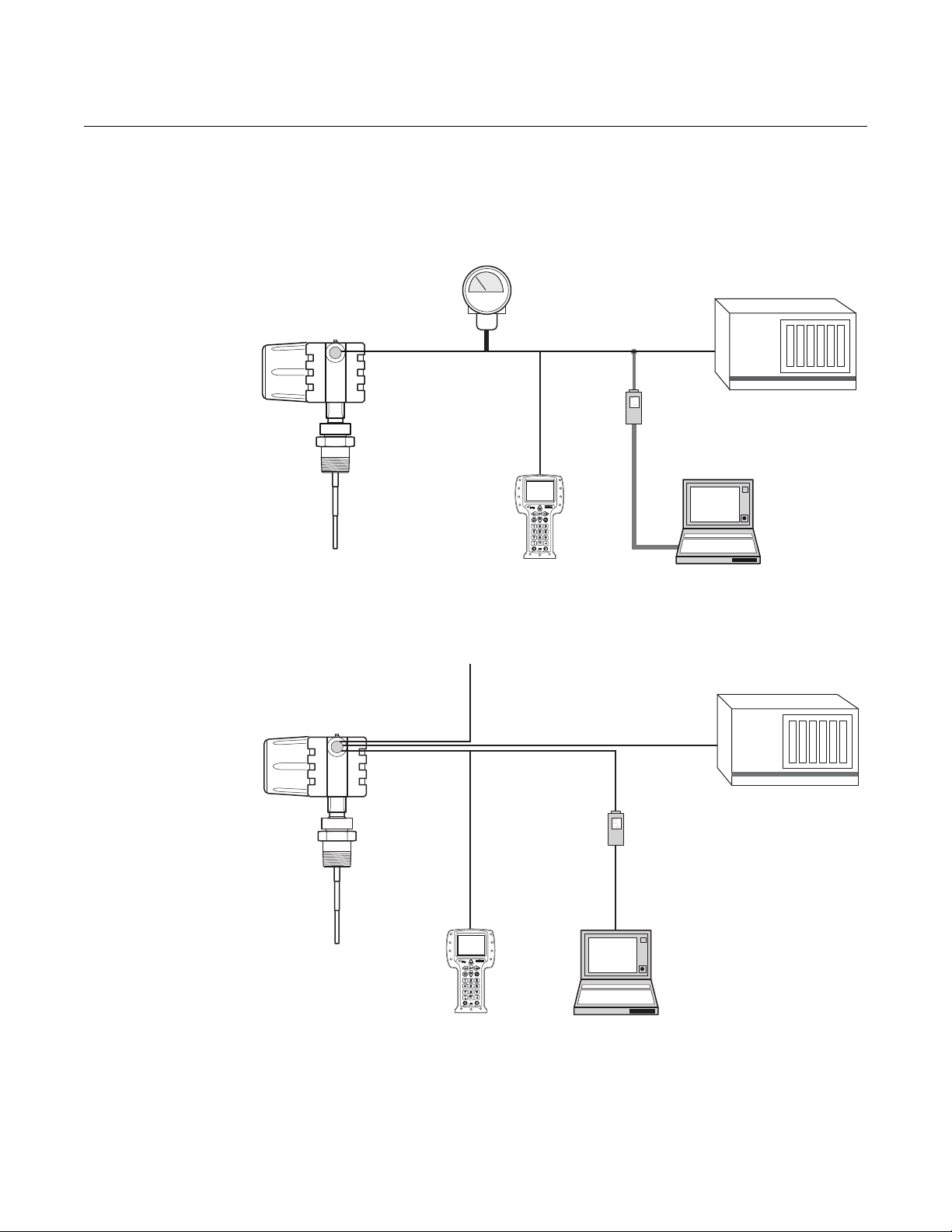
Control
System/PLC
HART
Modem
PC
Rosemount 3300 Series
transmitter
375 Field
Communicator
4-20 mA/HART
Modbus Control
System/PLC
HART
Modem
PC
Power
375 Field
Communicator
Max. cable length is
4000 ft. (1200 m)
MODBUS
Rosemount 3300 Series
transmitter
SYSTEM INTEGRATION
Figure 1-1. Rosemount 3300
Series: HART system.
Reference Manual
00809-0600-4811, Rev AA
February 2009
Figure 1-2. Rosemount 3300
Series: MODBUS system.
1-2

Reference Manual
Rosemount
5300 Series
Transmitter
Display
4-20 mA / HART
375 Field
Communicator
3 x 4-20 mA
Tri-loop
Control
System
HART
Modem
PC with Rosemount
RadarMaster
Host / DCS System (e.g. DeltaV
®)
Maintenance
H2 - High Speed Field Bus
H1 - Low Speed Field Bus
6234 ft. (1900 m) maximum
(depending upon cable
characteristics)
Fieldbus
Modem
PC with Rosemount
RadarMaster
Display
(option)
Rosemount 5601
Rosemount 5401
Rosemount 5301
375 Field
Communicator
Note:
Intrinsically safe
installations
may allow fewer
devices per I.S.
barrier due to
current
limitations.
00809-0600-4811, Rev AA
February 2009
Figure 1-3. Rosemount 5300
Series:
HART system.
Rosemount Radar Level Transmitters
Figure 1-4. Rosemount 5300
Series - F
OUNDATION™ fieldbus
system.
1-3

Rosemount Radar Level Transmitters
Reference Manual
00809-0600-4811, Rev AA
February 2009
1-4

Reference Manual
00809-0600-4811, Rev AA
February 2009
Rosemount Radar Level Transmitters
Section 2 Installation Considerations
Safety messages . . . . . . . . . . . . . . . . . . . . . . . . . . . . . . . . . page 2-1
Introduction . . . . . . . . . . . . . . . . . . . . . . . . . . . . . . . . . . . . . page 2-2
Mechanical Installation . . . . . . . . . . . . . . . . . . . . . . . . . . . page 2-2
Electrical Installation . . . . . . . . . . . . . . . . . . . . . . . . . . . . . page 2-12
SAFETY MESSAGES Procedures and instructions in this section may require special precautions to
ensure the safety of the personnel performing the operations. Information that
raises potential safety issues is indicated by a warning symbol ( ). Please
refer to the following safety messages before performing an operation
preceded by this symbol.
Explosions could result in death or serious injury.
Verify that the operating environment of the gauge is consistent with the appropriate
hazardous locations certifications.
Before connecting a HART-based communicator in an explosive atmosphere, make
sure the instruments in the loop are installed in accordance with intrinsically safe or
non-incendive field wiring practices.
Do not remove the gauge cover in explosive atmospheres when the circuit is alive.
Failure to follow safe installation and servicing guidelines could result in death or
serious injury.
Make sure only qualified personnel perform the installation.
Use the equipment only as specified in this manual. Failure to do so may impair the
protection provided by the equipment.
Do not perform any service other than those contained in this manual unless you are
qualified.
High voltage that may be present on leads could cause electrical shock.
Avoid contact with leads and terminals.
Make sure the main power to the Rosemount 3300 / 5300 Transmitter is off and the lines
to any other external power source are disconnected or not powered while wiring
the gauge.
Probes covered with plastic and/or with plastic discs may generate an ignition-capable
level of electrostatic charge under certain extreme conditions. Therefore, when the
probe is used in a potentially explosive atmosphere, appropriate measures must be
taken to prevent electrostatic discharge.
Process leaks could result in death or serious injury.
Make sure that the transmitter is handled carefully. If the Process Seal is damaged, gas
might escape from the tank if the transmitter head is removed from the probe.
www.rosemount.com

Reference Manual
00809-0600-4811, Rev AA
Rosemount Radar Level Transmitters
February 2009
INTRODUCTION In addition to selecting the appropriate radar level transmitter, mechanical
installation is one of the most critical steps of the commissioning procedure.
When done correctly, the subsequent transmitter configuration will be
considerably simplified.
The main focus of this section is to provide a framework for installations in a
variety of tanks and process connections typically found in the upstream oil
and gas industry.
MECHANICAL INSTALLATION
Recommended Mounting Position
Figure 2-1. Mounting Position.
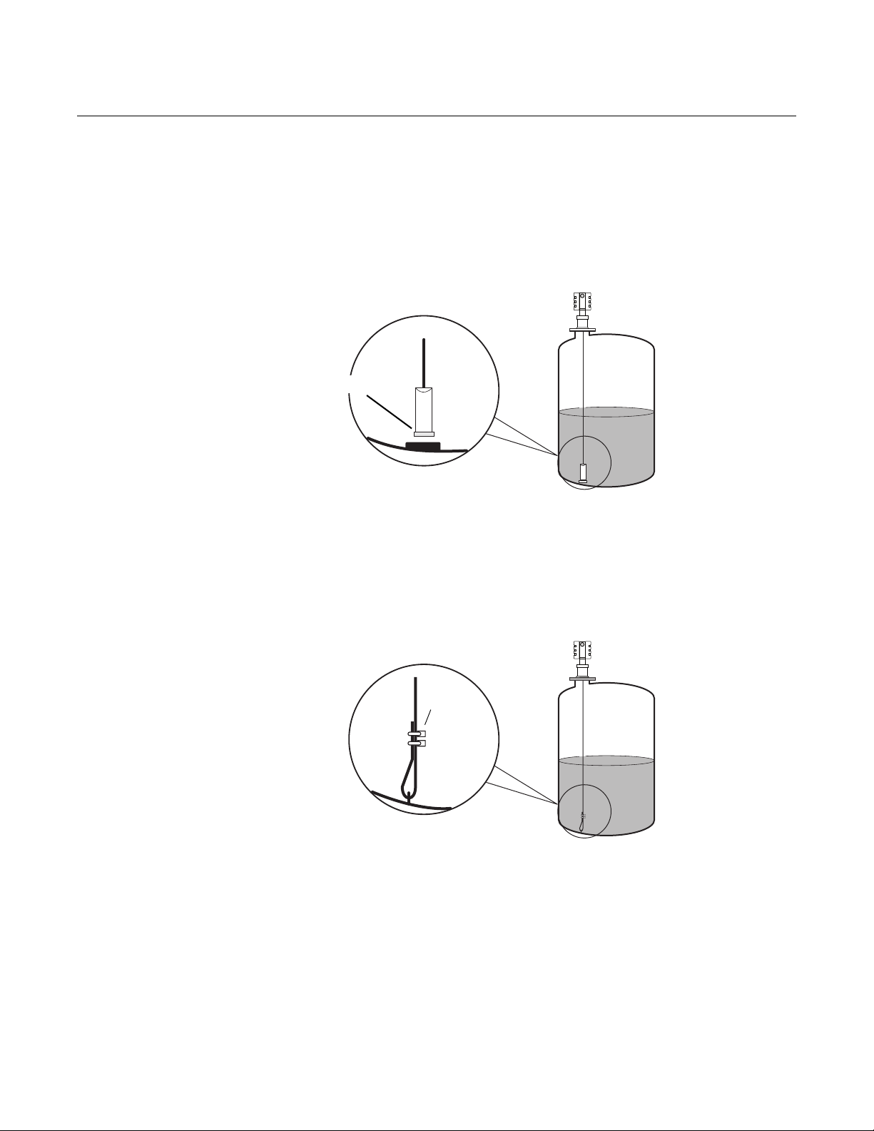
To find an appropriate mounting position for the transmitter, consider the
conditions of the tank. The transmitter should be mounted so that turbulence
from disturbing objects is reduced. If turbulence is present, the probe may
need to be anchored to the bottom.
2-2
Guidelines to be considered when mounting the transmitter:
• Do not mount close to inlet pipes
• If the probe sways because of turbulent conditions in the tank, the
probe should be anchored to the tank bottom. In these applications, the
best option is anchoring with a Magnet fastened to the weight
• Avoid mounting close to internal objects that are within 6 in. (150 mm)
from probe at any time
• The probe should not come into contact with the nozzle or other objects
in the tank
NOTE!
Violent fluid movements can cause forces that could break rigid probes.
Reference Manual
Magnet
Clamps
00809-0600-4811, Rev AA
February 2009
Figure 2-2. Anchoring the probe
with a magnet.
Rosemount Radar Level Transmitters
Anchoring a Flexible Single Lead probe
A magnet can be fastened to a threaded (M8x14) hole at the end of the
weight. Placing a metal plate beneath the magnet, as illustrated in Figure 2-2,
will help to guide the probe.
Magnets should not be used on long nozzle applications because the magnet
could attach to the side of the nozzle during installation.
Figure 2-3. Anchoring the probe
through a welded eye.
The probe rope can also be used for anchoring. The probe rope can be pulled
through a suitable anchoring point, e.g. a welded eye and fastened with two
clamps. The length from the underside of the flange to the top clamp should
be used to configure the probe length.
2-3
Rosemount Radar Level Transmitters
Make sure that the probe
does not come into
contact with the chamber
wall, e.g. by using a
centering disk.
A clearance
distance of 1 in.
(25 mm) between
the probe end and
the cage bottom is
recommended.
Installation in pipes
A centering disk is recommended when installing in pipes to prevent the
probe from contacting the chamber wall. The disk is attached to the end of the
probe to keep the probe centered in the chamber. The discs are available in
stainless steel (SST) and PTFE. The PTFE option is recommended for most
applications and the SST centering disk is used for high temperature
operations.
Figure 2-4. Improper and proper
probe positions.
Reference Manual
00809-0600-4811, Rev AA
February 2009
2-4
To avoid bending the probe (rigid probes) or twisting and coming in contact
with the chamber wall (flexible probes), a small clearance distance of 1 in.
(25 mm) between the centering disk and chamber bottom is recommended. It
should be selected with a dome shaped chamber bottom in mind, which may
prevent the centering disk from reaching the bottom.
Side-pipe locations and the effective measurement range are determined by
the mating tank connections. There are no constraints on the diameter of the
side-pipes, but build-up and clogging should be considered. Also the inlet
pipes should not protrude into the chamber since they may interfere with the
radar measurement. Always use the same construction material for the
chamber and the tank, otherwise, mechanical tensions can arise in the
side-connections.
The recommended chamber diameter is 3 in. (75 mm) or 4 in. (100 mm).
Chambers with a diameter less than 3 in. (75 mm) may have build-up
problems and it may also be difficult to center the probe. Chambers larger
than 6 in. (150 mm) can be used, but provide no advantages for the radar
measurement.
With the Rosemount 3300 / 5300 Series, single probes are recommended for
use in 3 in. (75 mm) and 4 in. (100 mm) chambers. Other probe types are
susceptible to build-up and should not be used in this application.
The probe must not touch the chamber wall and should extend the full height
of the chamber, but it does not need to touch the bottom of the chamber.
Probe type selection depends on the probe length:

Reference Manual
00809-0600-4811, Rev AA
February 2009
Rosemount Radar Level Transmitters
Less than 3 ft. (1 m): Use Single Rigid Probe and no centering disk is
needed. The transition zones and the height of the weight will limit the use of
single flexible probes shorter than 3 ft. (1 m).
Between 3 ft. (1 m) and 10 ft. (3 m): Use either Rigid Single or Flexible
Single Probe with the weight and centering disk. Rigid Single has smaller
transition zones, while the Flexible Single requires less head-space during
installation and is less likely to be damaged.
More than 10 ft. (3 m): Use Flexible Single Probe with a weight and centering
disk.
Light hydrocarbon applications not in chambers: Use the Rosemount
5300 Series with either a Rigid Single or Flexible Single Probe. In very light
hydrocarbons, the Rosemount 3300 signal loses too much energy on a single
probe. The Rosemount 5300 has more efficient and sensitive microwave
modules that increase signal strength. The 3300 will, however, work in light
hydrocarbon chamber applications, because chambers have similar physics
of propagation as the traditional coaxial style probe.
Transition Zones Transition zones, located at the very top and bottom of the probes, are
regions where measurement performance is reduced. Different factors affect
the size of the transition zones - probe type, centering disk or no centering
disk, and the material and media measured, as shown in Table 2-1.
Table 2-1. Transition Zones for
Rosemount 3300 and 5300
Series.
Dielectric
Constant
(2)
Upper
80 (water) 4 in. (10 cm) 4.3 in. (11.cm) 4 in. (10 cm) 4.3 in. (11 cm) 5.9 in. (15 cm) 4.3 in. (11 cm)
Transition
Zone
(3)
Lower
Transition
Zone
(1) Rigid Single Lead probe without SST centering disk or with PTFE centering disk.
(2) The distance from the upper reference point where measurements have reduced accuracy.
(3) The distance from the lower reference point where measurements have reduced accuracy.
(4) Note that the weight length adds to non-measurable area. For more information, see Dimensional Drawings in the Guided Wave Radar Level and Interface
Transmitter, Rosemount 3300 Series Product Data Sheet (Document No. 00813-0100-4811).
(5) The measuring range for the PTFE covered Flexible Single Lead probe includes the weight when measuring on a high dielectric media.
(6) Note that the weight length adds to non-measurable area. For more information, see Dimensional Drawings in the High Performance Guided Wave Radar,
Rosemount 5300 Product Data Sheet (Document No. 00813-0100-4530).
2 (oil) 4 in. (10 cm) 6.3 in. (16 cm) 4 in. (10 cm) 6.3 in. (16 cm) 20 in. (50 cm) 7.1 in. (18 cm)
80 (water) 2 in. (5 cm) 2 in. (5 cm) 2 in. (5 cm) 2 in. (5 cm) 2 in. (5 cm)
2 (oil) 4 in. (10 cm) 2.8 in. (7 cm) 8 in. (20 cm) 8 in. (20 cm) 4.7 in. (12 cm)
Rigid Single Lead
3300 5300 3300 5300 3300 5300
(1)
Rigid Single Lead, with
metallic centering disk
Flexible Single Lead
(4) (5)
0 in. (0 cm)
(4)
2 in. (5 cm)
(5) (6)
(6)
2-5
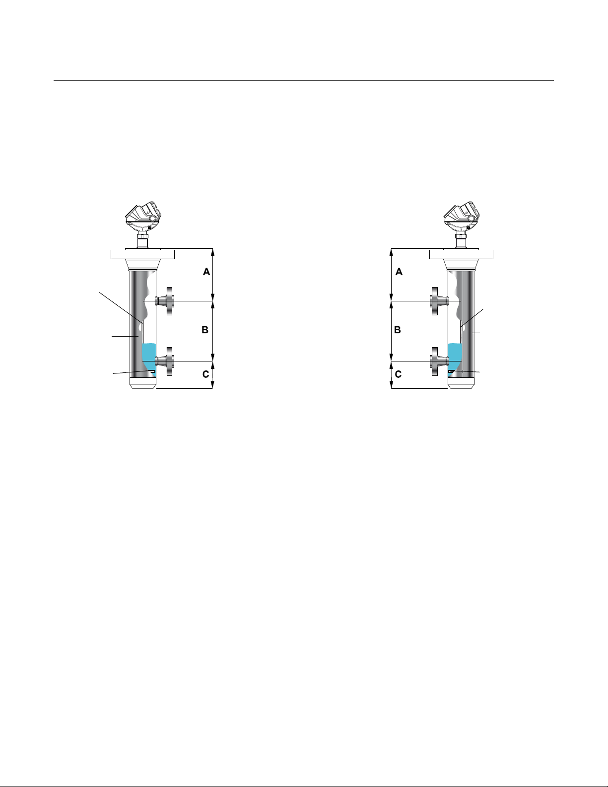
Rosemount Radar Level Transmitters
A > Upper transition zone
B = Effectice Measuring
Range, determined by
mating tank connections
C > Lower transition zone
including weight height
(for flexible probes) and
clearance distance
Single Flexible
for chambers
>= 3 ft. (1 m)
Probe/chamber
diameter must
be 3 in. or 4 in.
(7.5 cm or 10 cm)
Always use a
centering disk
Single Rigid
Probe/chamber
diameter must
be 3 in. or 4 in.
(7.5 cm or 10 cm)
Use centering
disks for probes
> 3 ft. (1 m)
The weight on the flexible probes reduces the measurement range.
Therefore, it is recommended to dimension the cage (A, C) so it does not
interfere with the effective measurement range (B). The transition zones also
limit the minimum probe length. See Figure 2-5 on page 2-6.
Figure 2-5. Measuring zones in
chambers.
Reference Manual
00809-0600-4811, Rev AA
February 2009
2-6

Reference Manual
UNZ H
Nozzle diameter (D)
Upper Null Zone (UNZ)
adjustments may be
needed for 2-in. (50 mm)
nozzles
Avoid nozzles with reducer
(unless using coaxial probe)
00809-0600-4811, Rev AA
February 2009
Rosemount Radar Level Transmitters
Process Connections There are a few different types of Process Connections used in these
applications. Below are some directions and guidelines on how to install and
what to consider for the various connections.
Flanged connections
Below are recommendations for the nozzle configuration and dimensions for
flanged installations on top of the tank/vessel.
Table 2-2. Nozzle
considerations.
Recommended Nozzle Diameter (D) 4-6 in. (100-150 mm)
Minimum Nozzle Diameter (D)
Maximum Nozzle Height (H) 4 in. (100 mm) + Nozzle Diameter
(1) An Upper Null Zone setup may be required to mask the nozzle, which may reduce
the measuring range.
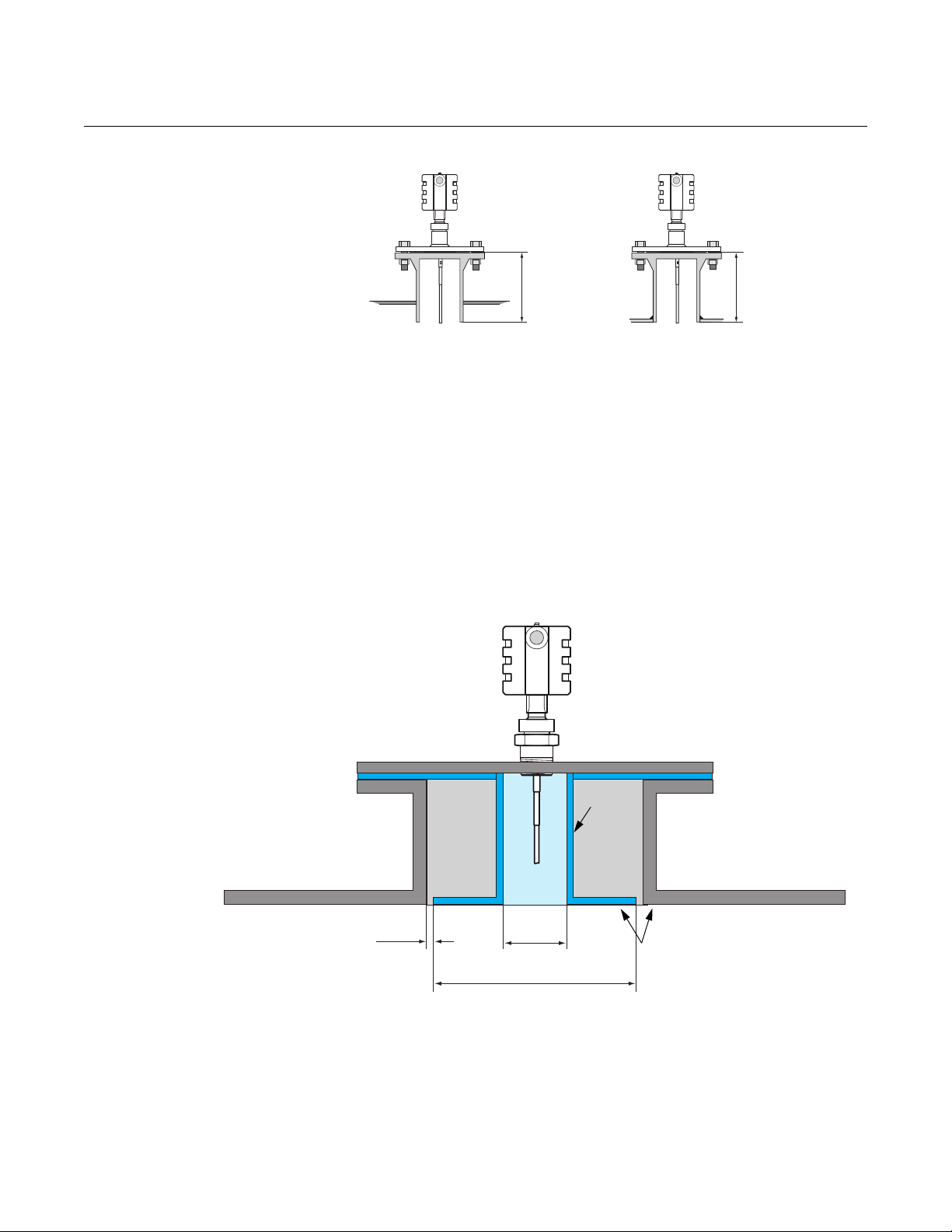
Nozzle height H is measured from the flange to the bottom of the nozzle,
regardless of how the nozzle is attached to the tank roof as illustrated in
Figure 2-6.
Single (Rigid / Flexible)
(1)
2 in. (50 mm)
2-7
Rosemount Radar Level Transmitters
HH
Tank roof
Tank r o o f
< ½ in. (13 mm)
6 in.
(150 mm)
Approx. flush within ± 1 in. (25 mm)
No need to be more than 15 in.
(380 mm) even for very large nozzles
for nozzles less than
15 in. ( 380 mm)
Inner
nozzle
Figure 2-6. Definition of nozzle
height H.
10-in. (250 mm) or larger flange/manway connection
If a Rosemount 3300/5300 Series Guided Wave Radar with single lead probe
is installed in a 10-in. (250 mm) (DN250) high nozzle or larger, there may be
resonance and double bounce problems. This can lead to measurement
errors for products with low dielectric constants, so 10-in. (250 mm) nozzles or
larger should be avoided.
In cases where 10-in. (250 mm) nozzles or larger are used, install an inner
steel nozzle with a smaller diameter, as illustrated in Figure 2-7.
Reference Manual
00809-0600-4811, Rev AA
February 2009
Figure 2-7. Special installation
considerations for 10 inch
nozzles.
Flat tank roof installation is not affected by this phenomenon.
2-8

Reference Manual
3 or 4 in.
(75 or 100 mm)
1 ½ in. (37.5 mm) NPT
Do not use Teflon tape
or similar
non-conductive
materials in the
threaded connections.
These connections
must be able to provide
a ground connection
between the probe and
the tank.
00809-0600-4811, Rev AA
February 2009
Figure 2-8. The Rosemount
3300 / 5300 can be installed in a
3 or 4 in. (75 or 100 mm) tank
opening by using an adaper.
Rosemount Radar Level Transmitters
Threaded tank connection
Many Oil and Gas applications have 3-in. (75 mm) or 4-in. (100 mm) threaded
connections on top of the tank roof.
For this connection, install the Rosemount 3300 / 5300 transmitters with a
1 ½-in. ( 37.5 mm) NPT threaded connection (model code option RA). The
probe can be attached to a bushing or adapter piece, reducing the tank
opening from a 3-in. (75 mm) or 4 in. (100 mm) threaded connection to the
desired 1 ½-in. (37.5 mm) standard Rosemount 3300 / 5300 process
connection.
2-9
Rosemount Radar Level Transmitters
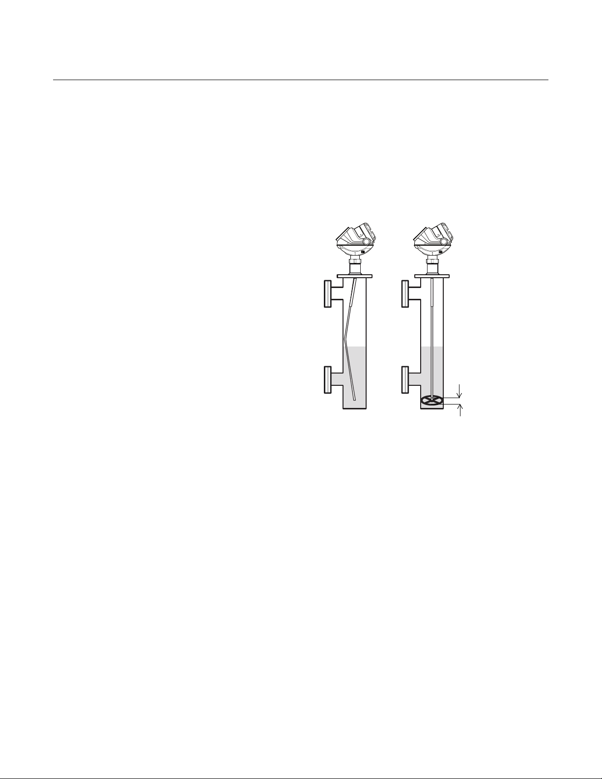
The illustration demonstrates the Long
Stud (LS) configuration in which the rigid
portion of the single flexible probe extends
the probe further into the vessel, thus
preventing the probe from contacting the
side of the vessel.
Rosemount 3300 or
5300 transmitter
Long Stud
Flexible Probe
Counter Weight
Side mounted process connection
In some cases, tanks might not have top process connections suitable for
installation of Guided Wave Radar units, so side mounted process
connections are a viable and reliable installation practice. Certain precautions
must be taken to ensure successful level measurements in these vessels.
Both flexible and rigid single lead probes can be utilized for these
installations.
A special mechanical configuration, Long Stud (model code option LS), can
be used for the Flexible Single Lead probe to prevent contact with walls or
nozzles. The Long Stud incorporates a longer rigid rod extension piece which
connects to the flexible portion of the probe. This is useful for side mounted
probes since it allows for the probe to extend further into the vessel before it is
bent vertically down towards the tank bottom. Figure 2-9 illustrates this type of
installation:
Figure 2-9. Side mounting with
Flexible Single Lead probe.
Reference Manual
00809-0600-4811, Rev AA
February 2009
2-10

Reference Manual
The single rigid probe is bent 90° at a
distance that will ensure that the probe
protrudes into the tank and away from
the tank wall.
Rigid Probe
90
° bend
Rosemount 3300 or
5300 transmitter
00809-0600-4811, Rev AA
February 2009
Figure 2-10. Side mounting with
Rigid Single Lead probe.
Rosemount Radar Level Transmitters
For side mounting with a Rigid Single Lead probe, the probe is bent at a 90°
angle to ensure that the probe extends into the tank and away from the tank
wall. Figure 2-10 illustrates this type of installation:
Non-metallic Process Connections
See “Non-metallic process connections“ on page 3-10.
2-11

Rosemount Radar Level Transmitters
For Explosion-proof/ Flameproof
applications the resistance
between the negative terminal on
the transmitter and the power
supply must not exceed 300
.
375 Field
Communicator
PC
Power Supply
Load Resistance 250
HART
modem
Rosemount 3300
Series Transmitter
Reference Manual
00809-0600-4811, Rev AA
February 2009
ELECTRICAL INSTALLATION
This is a brief description of the Rosemont 3300 and 5300 wiring procedure.
For more information, see the respective reference manual: Rosemount 3300
Series (Document No. 00809-0100-4811) and Rosemount 5300 Series
(Document No. 00809-0100-4530).
Rosemount 3300 Series:
HART
Version
The 3300 Series is a two-wire loop powered transmitter accepting power
supplies ranging from 11 Vdc to 42 Vdc. It uses 4-20 mA power superimposed
with a HART
signal. To connect the transmitter:
1. Make sure the power supply is disconnected.
2. Remove the cover on the transmitter housing terminal side (see label).
Do not remove the cover in explosive atmospheres when the circuit is
live. All power to the transmitter is supplied over the signal wiring.
3. Pull the cable through the cable gland/conduit.
4. Connect wires according to Figure 2-11 for non-intrinsically safe output.
Make sure that the transmitter housing is grounded in accordance with
national and local electrical codes. There are two grounding screw
connections provided. One is inside the Field Terminal side of the
housing identified by a ground symbol: , and the other is located on
top of the housing.
5. Attach and tighten the housing cover. Tighten the cable gland, plug and
seal any unused connections and connect the power supply.
Figure 2-11. Wiring diagram for non-intrinsically safe installations of the 3300.
2-12
For HART communication, a minimum load resistance of 250 within the
loop is required.
The power supply voltage ranges from V
Vdc to 42 Vdc where V
min
min
is the
minimum voltage given by:
11 V Non-hazardous locations certification
16 V Explosion-proof/flameproof certification

Reference Manual
RS-485 Bus
B
A
120
120
Power
Supply
HART -
HART +
In case it is the last transmitter on
the bus, connect the 120 terminator
resistor
120
00809-0600-4811, Rev AA
February 2009
Rosemount Radar Level Transmitters
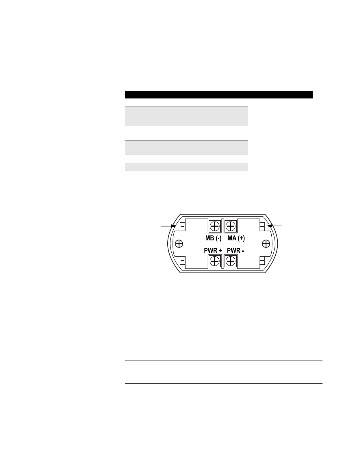
Rosemount 3300 Series: Modbus Version
To connect the Rosemount 3300:
1. Make sure the power supply is disconnected.
2. Remove the cover on the transmitter housing terminal side (see label).
Do not remove the cover in explosive atmospheres when the circuit is
live. All power to the transmitter is supplied over the signal wiring.
3. Pull the cable through the cable gland/conduit. For the RS-485 bus use
shielded twisted pair wiring, preferably with an impedance of 120
(typically 24 AWG) to comply with the EIA-485 standard and EMC
regulations. Maximum cable length is 4000 ft. (1200 m).
4. Connect wires according to Figure 2-12 and Table 2-3. Connect the lead
that originates from the “A” line from the RS-485 bus to the terminal
marked MA (+), and the lead that originates from the “B” line to the
terminal marked MB (-). Make sure that the transmitter housing is
grounded in accordance with national and local electrical codes. There
are three grounding screw connections provided. Two are inside the
Field Terminal side of the housing identified by a ground symbol:
and the other is located on top of the housing.
5. If it is the last transmitter on the bus, connect the 120 termination
resistor.
6. Connect the leads from the positive side of the power supply to the
terminal marked PWR +, and the leads from the negative side of the
power supply to the terminal marked PWR -. The power supply cables
must be suitable for the supply voltage and approved for use in
hazardous areas, where applicable.
7. Attach and tighten the housing cover. Tighten the cable gland, plug and
seal any unused connections and connect the power supply.
,
Figure 2-12. Field Wiring Connection for the 3300 with Modbus.
2-13
Rosemount Radar Level Transmitters
HART +
HART -
Connection Terminals
The connection terminals are described in Table 2-3 below:
Reference Manual
00809-0600-4811, Rev AA
February 2009
Table 2-3. Connection
Te rm i na l s
Figure 2-13. Connection Terminals
for Rosemount 3300 with Modbus
Connector label Description Comment
HART + Positive HART connector Connect to PC with RCT
software, 375 Field
HART - Negative HART connector
MA (+)
MB (-)
PWR + Positive Power input terminal
PWR - Negative Power input terminal
(1) The designation of the connectors do not follow the EIA-485 convention, which
states that RX/TX- should be referred to as 'A' and RX/TX+ as 'B'.
Modbus RS-485 A connection
(RX/TX+)
Modbus RS-485 B connection
(RX/TX-)
(1)
(1)
Communicator, or other
HART configurators
Connect to Modbus
Master
Apply +8 Vdc to +30 Vdc
PC Communication with MA(+) MB(-)
2-14
The Rosemount 3300 level transmitter can be configured with the Rosemount
Configuration Tools (RCT) software by using the MA (+), MB (-) connectors.
The PC communicates with the 3300 by transferring the HART protocol over
the RS-485. This requires using a RS-232/RS-485 Converter.
To communicate with the 3300 transmitter, the COM port used for serial
communication (RS-232) must be selected in RCT. Check the Device
Manager in Windows if unsure which COM port to use.
See Help, Contents in RCT for information on how to use a specific COM port.
NOTE
Make sure the 3300 transmitter is alone on the bus and disconnect or turn off
power from other devices.
Reference Manual
Isolator
Loop Resistor
3300 Series EEX d housing
4-20 mA
regulator
Ground current path broken by isolator
- 12 V
+ 12 V
00809-0600-4811, Rev AA
February 2009
Rosemount Radar Level Transmitters
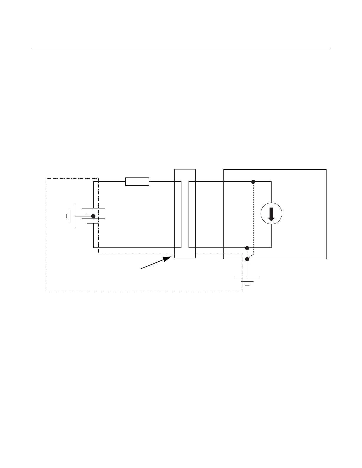
Cathodic Protection The ground plane voltage is elevated in applications where the tank is
protected by a Cathodic Protection System. For HART units, an isolator
should be used to protect the circuits from ground currents. A Modbus unit is
more robust against ground currents, and can handle a difference of ground
voltages of up to 20 V without using an Isolator.
Using an Isolator avoids undesired ground current in the 4-20 mA loop that
may interfere with the correct 4-20 mA output. Installing an isolator ensures
galvanic isolation between the control system and the transmitter and will
break the undesired loop, preventing interference with the wanted output.
Figure 2-14. 4-20 mA loop with
isolator to ensure galvanic
isolation.
Figure 2-14 above shows a 4-20 mA loop with isolator installed.
We recommend a loop powered isolator made by Dataforth;
http://www.dataforth.com/catalog/pdf/DSCL22.pdf. Rosemount part
number:DSCL22-01.
2-15

Rosemount Radar Level Transmitters
Ter min al
Block
Cover
External Ground Screw
Terminals for signal
and power supply
Cable
Entry
Cable
Entry
Internal Ground Screw
Reference Manual
00809-0600-4811, Rev AA
February 2009
Rosemount 5300 Series: HART Version
The Rosemount 5300 Series transmitter operates with a power supply
ranging from 16-42.4 V (16-30 V in IS applications, 20-42.4 V in
explosion-proof / flameproof applications). All configuration tools for HART
communication, such as the Rosemount 375 Field Communicator and
Rosemount Radar Master, require a minimum load resistance (RL) of 250
within the loop to function properly. See the diagrams below.
To connect the transmitter:
1. Make sure the housing is grounded (including IS ground inside Terminal
compartment) according to Hazardous Locations Certifications, national,
and local electrical codes.
2. Verify the power supply is disconnected.
3. Remove the terminal block cover (see Figure 2-15).
4. Pull the cable through the cable gland / conduit. For explosion-proof /
flameproof installations, only use cable glands or conduit entry devices
certified explosion-proof or flameproof.
5. Install wiring with a drip loop where the bottom of the loop must be lower
than the cable / conduit entry.
6. To connect the wires, see Figure 2-16.
7. Use the enclosed metal plug to seal any unused port.
8. Mount the cover and tighten the cable gland making sure the cover is
fully engaged to meet explosion-proof requirements (adapters are
required if M20 glands are used). For ATEX and IECEx installations, lock
the cover with the locking screw.
9. Connect the power supply.
Figure 2-15. Rosemount 5300
Series Terminal Block.
NOTE!
Use PTFE tape or other sealant at the NPT threads in the Cable Entries.
2-16

Reference Manual
Power
Supply
HART
Modem
PC
Load
Resistance
250
Rosemount 375
Handheld
Communicator
Rosemount 5300 Series
Radar Level Transmitter
00809-0600-4811, Rev AA
February 2009
Figure 2-16. Wiring diagram for
non-intrinsically safe
installations of the Rosemount
5300 with HART.
Rosemount Radar Level Transmitters
2-17

Rosemount Radar Level Transmitters
Rosemount 5300 Series
Radar Level Transmitter
375 Field
Communicator
Fieldbus
Modem
PC
Power
Supply
Reference Manual
00809-0600-4811, Rev AA
February 2009
Rosemount 5300 Series: FOUNDATION™ fieldbus Version
The 5300 Series transmitter, FOUNDATION™ fieldbus version, operates with a
power supply ranging from 9-32 V (9-30 V in IS applications and 16-32 V in
explosion-proof / flameproof applications) FISCO, IS applications: 9-17.5 V.
To connect the transmitter:
1. Make sure the housing is grounded (including IS ground inside terminal
compartment) according to Hazardous Locations Certifications, national,
and local electrical codes.
2. Verify the power supply is disconnected.
3. Remove the terminal block cover (see Figure 2-15).
4. Pull the cable through the cable gland / conduit. For explosion-proof /
flameproof installations, only use cable glands or conduit entry devices
certified explosion-proof or flameproof. Install wiring with a drip loop
where the bottom of the loop must be lower than the cable / conduit
entry.
5. To connect the wires, see Figure 2-17.
6. Use the enclosed metal plug to seal any unused port.
7. Mount the cover and tighten the cable gland making sure the cover is
fully engaged to meet explosion-proof requirements (adapters are
required if M20 glands are used). For ATEX and IECEx installations, lock
the cover with the locking screw.
8. Connect the power supply.
Figure 2-17. Wiring diagram for
non-intrinsically safe
installations of Rosemount 5300
with F
OUNDATION™ fieldbus.
2-18

Reference Manual
00809-0600-4811, Rev AA
February 2009
Rosemount Radar Level Transmitters
Section 3 Upstream Applications
Specific Applications . . . . . . . . . . . . . . . . . . . . . . . . . . . . . page 3-1
Separators . . . . . . . . . . . . . . . . . . . . . . . . . . . . . . . . . . . . . . page 3-2
Production/Slop Tanks . . . . . . . . . . . . . . . . . . . . . . . . . . . . page 3-7
Slop tanks . . . . . . . . . . . . . . . . . . . . . . . . . . . . . . . . . . . . . . page 3-9
SPECIFIC APPLICATIONS
This document primarily describes two areas where our Guided Wave Radar
product is an excellent choice for level or level & interface measurements.
The areas are Gas Well and Oil Well applications. There are primarily three
types of applications at these production sites:
• Separator tanks (horizontal or vertical)
• Production tanks
•Slop tanks
The main difference between the tanks referenced above is the process or
product they contain. In gas wells, condensate (NGL) and water are the
primary products, whereas crude oil and water are the primary products in oil
wells.
The following description recommends which Rosemount Guided Wave
Radar transmitter to use for the different applications, along with details on the
proper model code for ordering. A complete list of recommended model code
information is found in Appendix A.
www.rosemount.com

Rosemount Radar Level Transmitters
SEPARATORS
Reference Manual
00809-0600-4811, Rev AA
February 2009
Horizontal separator (bullet tank)
Transmitter and probe selection
Horizontal separators are typically smaller in diameter and are used in both
Gas and Oil fields. The recommended installation is a Rosemount 3300 with a
Single lead probe.
Single Rigid Probes (model code option 4A) may be used if the tank height is
less than 9 ft. 10 in. (3 m 250 mm), and for anything taller, a Single Flexible
Probe (model code option 5A) must be used. If there is a high risk for a rigid
probe bending during installation, a flexible probe can be used on anything
taller than 3 ft. 4 in. (1 m 100 mm).
There are different materials of construction that can be used for the probes.
However, Stainless Steel (316/316L) is sufficient for the majority of these
applications, but material compatibility should be verified for each application.
Tank seal selection
The operating temperature is normally ambient temperature, however, the
pressure will vary in different applications/separators. The product
alternatives are either the Standard pressure and temperature tank seal
(model code option S) or the High Pressure tank seal (model code option P).
• The standard seal is rated to 580 psig (40 bar) at maximum 302 °F
(150 °C).
• The High Pressure tank seal is rated to 3500 psig (243 bar) at
maximum 392 °F (200 °C) or higher pressure for a lower temperature,
up to 5000 psig (345 bar) at a maximum of 100 °F (38 °C).
3-2
Model selection
The Rosemount 3302 is used for Level & Interface applications. If there is no
interface and only level is required, the transmitter can be configured for Level
measurement only. The separators have mounting connections either on the
top or on the side of the bullet tank in a chamber. See “Process Connections”
on page 2-7.

Reference Manual
• The standard seal is rated to maximum
580 psig (40 bar) at maximum 302 °F
(150 °C)
• The High Pressure tank seal is rated to
maximum 3524 psig (243 bar) at
maximum 392 °F (200 °C) or higher
pressure for a lower temperature, up to
5000 psig (345 bar) at a maximum of
100 °F (38 °C)
• One advantage of using Guided Wave
Radar technology is that it can cut through
foam because of its lower frequency
00809-0600-4811, Rev AA
February 2009
Rosemount Radar Level Transmitters
Vertical separator (vertical cylinder tank)
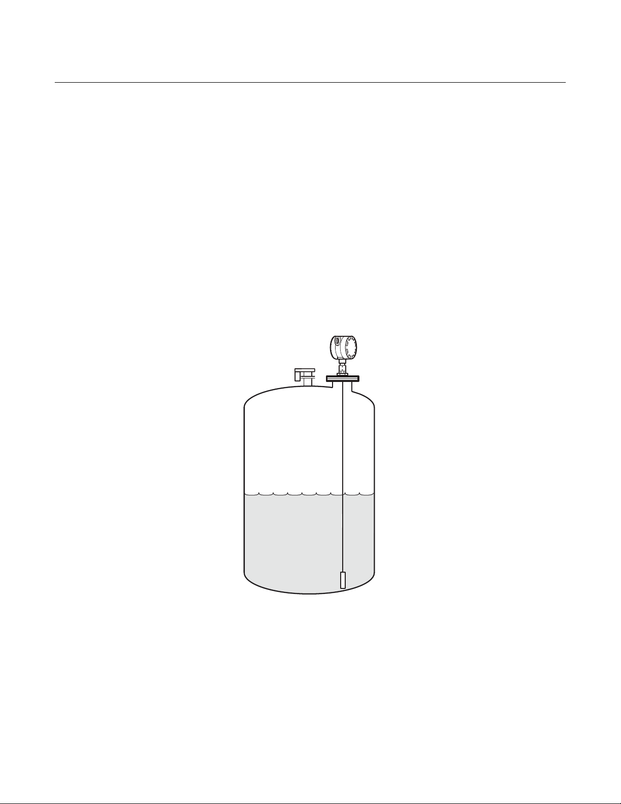
Figure 3-1. The Rosemount
3300 transmitter can be installed
on vertical separator tanks.
Transmitter and probe selection
Vertical separators vary in tank height and are used in both gas and oil fields.
The recommended product selection is a Rosemount 3300 with a Single lead
probe. It can be installed on top of the tank. On tall vertical cylinders, the 3300
may be installed on a chamber on the lower side of the separator with the
probe fully immersed.
Single Rigid Probes (model code option 4A) may be used if the tank height is
less than 9 ft. 10 in. (3 m 250 mm), and for anything taller, a Single Flexible
Probe (model code option 5A) must be used. If there is high risk for a rigid
probe bending during installation, a flexible probe can be used on anything
taller than 3 ft. 4 in. (1 m 100 mm). If the flexible probe version is used, select
the probe type that has a weight attached to the end (model code option 5A).
Tank seal selection
The operating temperature is normally ambient temperature, but the pressure
will vary in different applications/separators. One of the following product
alternatives should be selected:
• Standard pressure and temperature tank seal (model code option S)
• High Pressure tank seal (model code option P)
Model selection
Rosemount 3302 is used for Level & Interface applications in situations where
the probe is not fully immersed. The 3302 can be reconfigured for fully
immersed applications in chambers. The separators have mounting
connections either on top of the vertical tank or in a chamber on the lower side
of the tank. These process connections are used for interface measurement.
See “Process Connections” on page 2-7 for recommendations on different
process connections.
3-3
Rosemount Radar Level Transmitters
Reference Pulse
Level
Interface
Signal Amplitude
Thickness
Distance
Probe End
2
4
5
0.05
Level
Interface
Tank Height = 16.4 ft. (5 m)
Probe Length = 16.2 ft. (4.95 m)
Time
Probe End Distance
Height (m)
Reference Manual
00809-0600-4811, Rev AA
February 2009
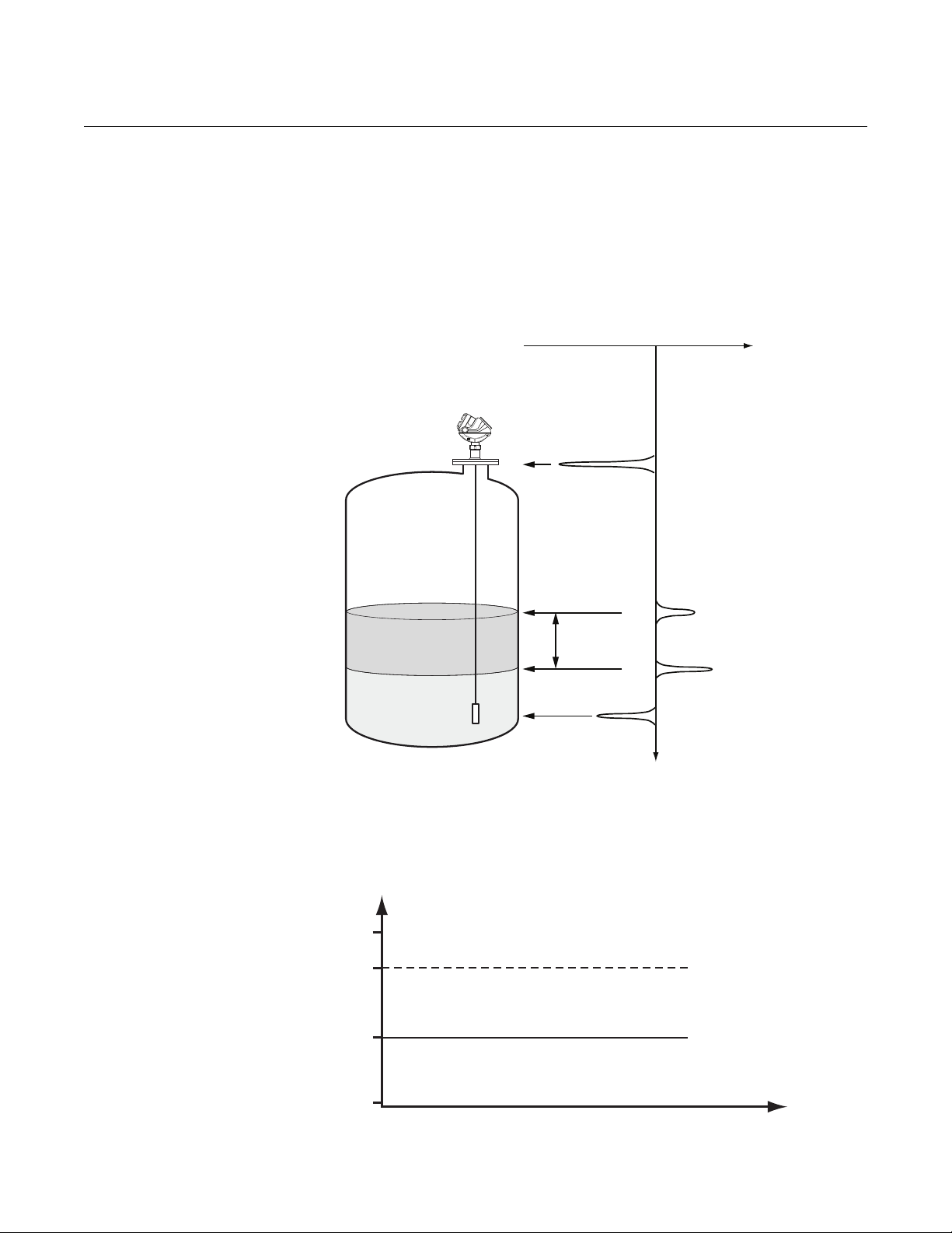
Output measurement at different interface levels
Figure 3-2. Measurement levels.
Interface measurement depends on several factors. If the tank contains two
products, level, interface, and thickness can be measured. However, if the
upper or the lower product is pumped out, the peaks of the waveform plot
must be interpreted properly to get precise measurement data.
Figure 3-2 gives an overview of the various echoes presented on a waveform
plot when two products are found.
Figure 3-3. Level measurement
when both products are in the
tank.
3-4
Figure 3-3 shows how this state is presented on a waveform plot.
In the example below, tank height is 16.4 ft. (5 m), and probe length is 16.2 ft.
(4.95 m).
Reference Manual
Time
Level
Interface
Probe End Distance
Height (m)
00809-0600-4811, Rev AA
February 2009
Figure 3-4. The lower product is
pumped out of the tank.
Rosemount Radar Level Transmitters
Figure 3-4 illustrates the output signals presented as the lower product is
pumped out.
Level = 4 m
Interface = 2 m
Thickness = 2 m
5
Level = 2 m
4
2
0.05
Interface = 0.05 m
Thickness = 1.95 m
NOTE!
The measured thickness is different before and after emptying the lower
product. The level measurement is done until it reaches the end of the probe.
When the lower product reaches the probe end, the signal generated turns
into a constant, horizontal line, but no longer shows the actual interface. It
also effects the thickness measurement.
The plot shows that there is a large layer of the upper product left after the
lower product has been pumped out. In this case, both the upper product
surface echo and the probe end echo are easily detected. The level and
interface will not have the same value. The level will be set to the level of the
upper product, and the interface (level) will be set to the probe end level.
If both the upper and lower products are pumped out, the level and interface
(level) will have the same value until both the upper product surface echo and
the probe end echo can be detected.
Thickness is measured from the product surface (level) to the interface.
However, if the lower product is pumped out, the thickness will be measured
from the product surface to the probe end only, since further signs cannot be
detected.
When the tank refills, the level and interface output will be the same. Interface
is not detectable until the minimum thickness requirement is reached.
3-5
Rosemount Radar Level Transmitters
2
4
Level = 4 m
Interface = 2 m
Thickness = 2 m
5
Level = Interface = 2 m
Thickness = 0 m
0.05
Time
Level = Interface
Height (m)
Probe End Distance
If the upper product is pumped out of the tank, interface measurement is
presented as illustrated in Figure 3-5:
Figure 3-5. The upper product is
pumped out of the tank.
Reference Manual
00809-0600-4811, Rev AA
February 2009
3-6
Reference Manual
00809-0600-4811, Rev AA
February 2009
Rosemount Radar Level Transmitters
PRODUCTION/SLOP TANKS
Vertical cylinder Transmitter and probe selection
Vertical cylinder tanks are holding or storage tanks where the separated
product (oil or condensate) is stored before it is moved to the next step in the
exploration process. These vertical cylinders vary in tank height.
If the tank is metallic, a Rosemount 3300 transmitter is sufficient. However, for
a non-metallic tank, a Rosemount 5300 transmitter is required for additional
EMI protection. Non-metallic tanks expose the probe to signal interference
from nearby motors or cables. The 5300 provides a more stable microwave
signal and improves EMI performance resulting in a more robust
measurement. The recommended product selection is a Rosemount 3300
with single flexible probe with a weight attached to the bottom (model code
option 5A).
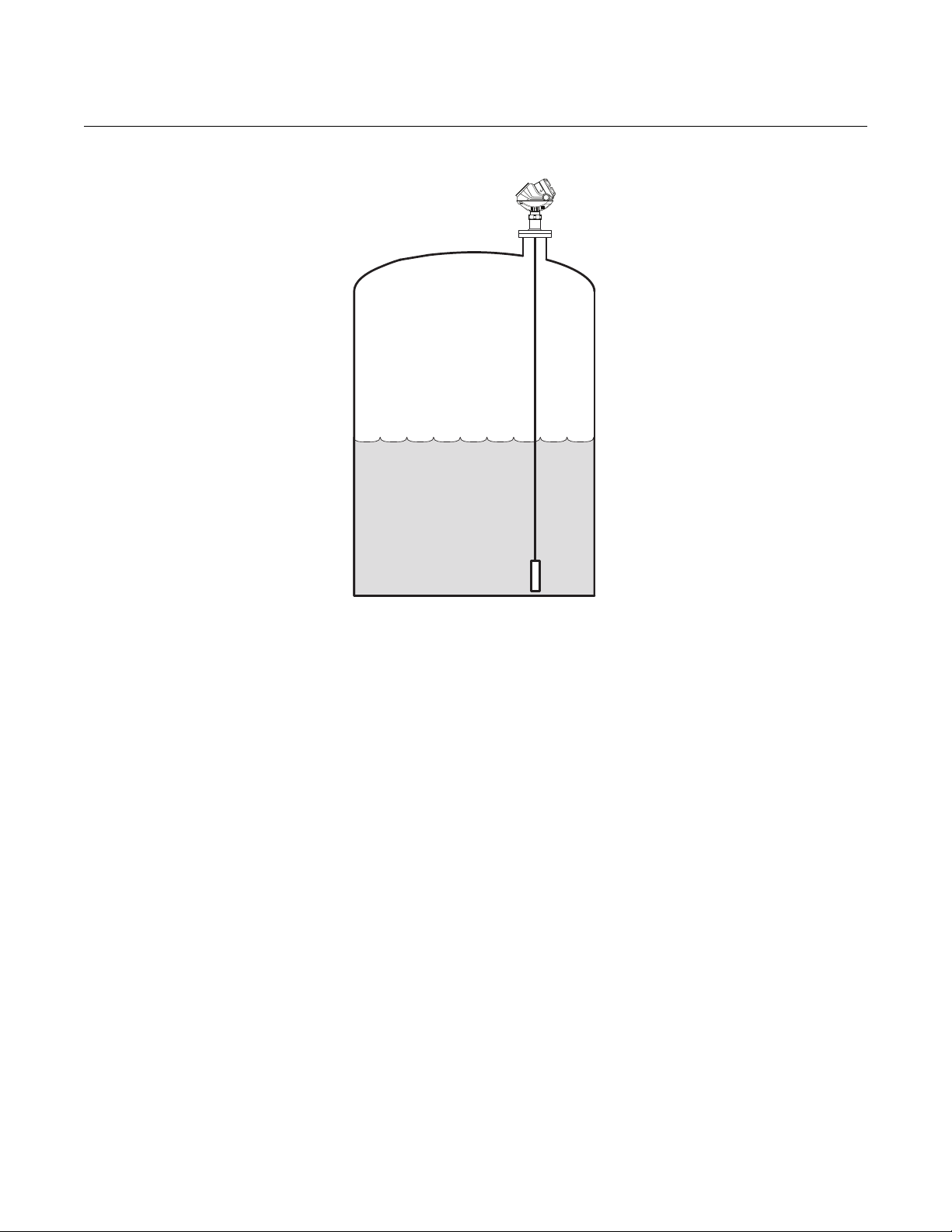
Figure 3-6. The Rosemount
3300 with Single Flexible probe
is suitable for metallic Vertical
cylinder storage tanks.
3-7
Rosemount Radar Level Transmitters
Figure 3-7. The Rosemount
5300 with Single Flexible probe
is suitable for non-metallic (i.e.
Fiberglass) storage tanks.
Reference Manual
00809-0600-4811, Rev AA
February 2009
Tank seal selection
Vertical cylinder tanks are usually vented to the atmosphere, but some have a
vapor recovery system so the Rosemount 3300 standard tank seal is suitable.
For this application the Standard pressure and temperature tank seal version
(model code option S) should be used. The standard seal is rated from full
vacuum to maximum 580 psig (40 bar) at maximum 302 °F (150 °C).
Model selection
Most of these installations require both level and interface measurement,
while some only require level measurement.
For metallic tanks, a Rosemount 3302 allows for configuring the 3300 for
either Level & Interface mode or just Level.
For non-metallic tanks, a Rosemount 5302 allows for configuring the 5300 for
either Level & Interface mode or just Level.
3-8
Reference Manual
00809-0600-4811, Rev AA
February 2009
Rosemount Radar Level Transmitters
SLOP TANKS
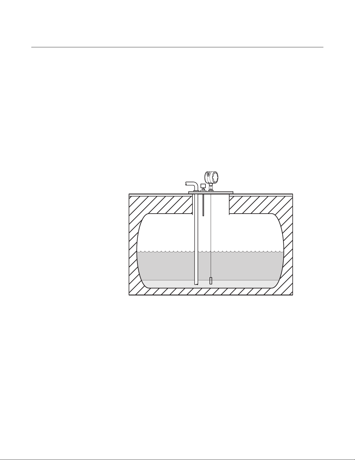
Underground or open pit Transmitter and probe selection
Oily and dirty water, as well as residue, are pumped into slop tanks for
temporary storage until further processing. Slop tanks are sometimes
underground tanks, or open pits often covered with a metal cover/plate.
A Rosemount 3300 with single lead probe is recommended. Single Rigid
Probes (model code option 4A) may be used if the tank height is less than
9 ft. 10 in. (3 m 250 mm). For anything taller, a Single Flexible Probe (model
code option 5A) must be used. If there is a high risk for a rigid probe bending
during installation, a flexible probe can be used on anything taller than
3 ft. 4 in. (1 m 100 mm).
If the flexible probe version is used, select the probe type that has a weight
attached to the end (model code option 5A).
Tank seal selection
These tanks are usually vented to the atmosphere, but some have a vapor
recovery system so the Rosemount 3300 standard tank seal is suitable.
For this application the Standard pressure and temperature tank seal version
(model code option S) should be used. The standard seal is rated from full
vacuum to maximum 580 psig (40 bar) at maximum 302 °F (150 °C).
Model selection
Most of these installations require both level and interface measurement,
while some only require level measurement.
Using a 3302 allows for configuring the 3300 for either Level & Interface mode
or just Level.
3-9

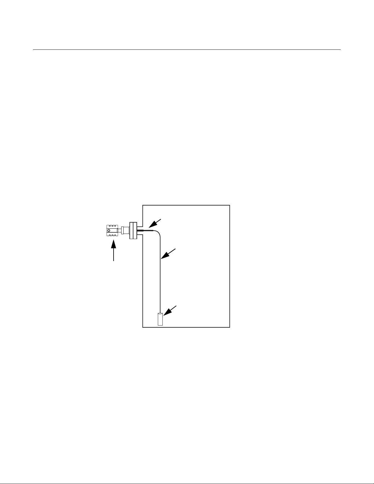
Rosemount Radar Level Transmitters
Metal flange Ø>2”/DN50
Metal sheet Ø>8”/200 mm
Non-metallic nozzle
Non-metallic nozzle
Do not use Teflon tape
or similar
non-conductive
materials in the
threaded connections.
These connections
must be able to provide
a ground connection
between the probe and
the tank.
Non-metallic process connections
For optimum measurement performance in non-metallic tanks, the
Rosemount 5300 Series is required. For tanks with non-metallic process
connections, the probe must be mounted with a metal flange, or screwed in to
a metal sheet (d>8 in./200 mm) if the threaded version is used.
Figure 3-8. Mounting in
non-metallic process
connections.
Reference Manual
00809-0600-4811, Rev AA
February 2009
3-10

Reference Manual
00809-0600-4811, Rev AA
February 2009
Rosemount Radar Level Transmitters
Section 4 Commissioning
Safety messages . . . . . . . . . . . . . . . . . . . . . . . . . . . . . . . . . page 4-1
Introduction . . . . . . . . . . . . . . . . . . . . . . . . . . . . . . . . . . . . . page 4-2
Commissioning . . . . . . . . . . . . . . . . . . . . . . . . . . . . . . . . . . page 4-2
Plotting the Measurement Signal . . . . . . . . . . . . . . . . . . . page 4-5
SAFETY MESSAGES Procedures and instructions in this section may require special precautions to
ensure the safety of the personnel performing the operations. Information that
raises potential safety issues is indicated by a warning symbol ( ). Please
refer to the following safety messages before performing an operation
preceded by this symbol.
Explosions could result in death or serious injury.
Verify that the operating environment of the gauge is consistent with the appropriate
hazardous locations certifications.
Before connecting a HART-based communicator in an explosive atmosphere, make
sure the instruments in the loop are installed in accordance with intrinsically safe or
non-incendive field wiring practices.
Do not remove the gauge cover in explosive atmospheres when the circuit is alive.
Failure to follow safe installation and servicing guidelines could result in death or
serious injury.
Make sure only qualified personnel perform the installation.
Use the equipment only as specified in this manual. Failure to do so may impair the
protection provided by the equipment.
Do not perform any service other than those contained in this manual unless you are
qualified.
High voltage that may be present on leads could cause electrical shock.
Avoid contact with leads and terminals.
Make sure the main power to the Rosemount 3300 / 5300 transmitter is off and the lines
to any other external power source are disconnected or not powered while wiring
the gauge.
Probes covered with plastic and/or with plastic discs may generate an ignition-capable
level of electrostatic charge under certain extreme conditions. Therefore, when the
probe is used in a potentially explosive atmosphere, appropriate measures must be
taken to prevent electrostatic discharge.
www.rosemount.com

Reference Manual
00809-0600-4811, Rev AA
Rosemount Radar Level Transmitters
February 2009
INTRODUCTION This section is a brief outline of commissioning, and does not provide
comprehensive information on the whole procedure.
To execute the commissioning process, the product-related Quick Installation
Guides steps are to be followed.
COMMISSIONING The transmitter installation should be carried out as described in the Quick
Installation Guide, enclosed with every transmitter. Even though the
transmitter may be installed on the bench, it must be configured according to
the actual process conditions.
Do not bend the probe during any part of the installation. If it is necessary,
shorten the probe, mount a centering disk, or anchor the probe during the
mechanical installation. For more information see the respective Reference
Manuals:
• Rosemount 5300 Series Reference Manual
(Document No. 00809-0100-4530)
• Rosemount 3300 Series Reference Manual
(Document No. 00809-0100-4811)
Beside these required steps, it is recommended as best practice to perform a
Trim Near Zone, save a backup of the transmitter settings, and save the initial
echo curve plot.
Trim Near Zone The Rosemount 3300 / 5300 Series transmitters are equipped with a firmware
functionality that minimizes the Upper Transition Zone based on the actual
mounting conditions.
To activate this functionality, ensure that the tank or chamber is empty,
alternatively, that the (upper) product is no closer than 40 in. (1 m), and then
execute the Trim Near Zone command.
For the Rosemount 3300 Series, the Trim Near Zone command can be
completed in the Radar Configuration Tools (RCT) software. Follow these
steps to conduct a Trim Near Zone:
4-2
Reference Manual
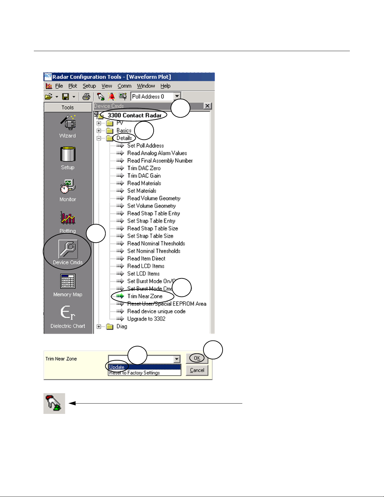
1. Click the Device Cmds tool.
2. Double-click 330x.
3. Click Details.
4. Double-click Trim Near Zone.
5. Select Update.
6. 6. Click OK.
7. Wait 1 minute.
8. Restart the device clicking
this icon.
1
2
3
4
5
6
4
00809-0600-4811, Rev AA
February 2009
Rosemount Radar Level Transmitters
4-3

Rosemount Radar Level Transmitters
For the Rosemount 5300 Series, the Trim Near Zone command can be
completed with the Rosemount Radar Master (RRM) software. The function is
found in the Advanced Configuration screen.
Rosemount Radar Master > Advanced > Near Zone > Trim Near Zone
Figure 4-1. The Trim Near Zone
command is on the Advanced
Configuration screen.
Reference Manual
00809-0600-4811, Rev AA
February 2009
Store Backup and Verification Files
For detailed information on the Trim Near Zone functionality, refer to
Rosemount 3300 (Document No. 00809-0100-4811) or 5300 Series
Reference Manuals (Document No. 00809-0100-4530).
As the last step of the commissioning procedure, it is recommended that both
the transmitter settings and the echo curve be stored. These can be used for
subsequent transmitter verification or troubleshooting.
For the 3300 Series in RCT, use the following procedure:
Radar Configuration Tools > View > Setup > Basics > (right click)
Receive All > (right click) Save Setup
Radar Configuration Tools > View > Plotting > Start the plot reading
and disk logging
For the 5300 Series in RRM, use the following procedure:
Rosemount Radar Master > Device > Backup Config to file
Rosemount Radar Master > Tools > Echo Curve > Record
4-4

Reference Manual
Product surface
End of Probe
Reference pulse
Product interface
00809-0600-4811, Rev AA
February 2009
Rosemount Radar Level Transmitters
PLOTTING THE MEASUREMENT SIGNAL
Plotting the Measurement Signal for the Rosemount 3300 Series
Figure 4-2. Example of a 3300
Series Waveform plot.
The 3300 Series and 5300 Series are compatible with different softwares for
plotting the measurement signal. The 3300 Series transmitter utilizes the
Radar Configuration Tools (RCT) software, while the 5300 Series transmitter
utilizes the Rosemount Radar Master (RRM) software.
The two software configuration programs have similar functions. Both
programs have the ability to plot the measurement signal. This section
explains how to view plots in RCT and RMM, and highlights the differences
between the two plot views.
For the 3300 Series, the Radar Configuration Tools (RCT) program has
powerful tools for advanced troubleshooting. Using the Waveform Plot
function gives an instant view of the tank signal.
To plot the measurement signal:
1. Start the Radar Configuration Tools program by clicking the RCT desktop
icon: .
2. Choose View > Plotting menu option, or choose the Plotting icon in
the RCT workspace (Tools pane at the left-hand side of the workspace)
and click the Read button.
The plot shows peaks for the product surface (P2), reference pulse (P1) and
end of probe (EOP). The probe end may not always be visible depending on
the amount of product above.
T1 - amplitude threshold for detection of the Reference pulse P1.
T2 - amplitude threshold for detection of the product level peak P2.
T3 - amplitude threshold for detection of the interface level peak P3.
T4 - amplitude threshold that is used to detect whether the probe is fully
immersed in the upper product or not.
4-5

Rosemount Radar Level Transmitters
Reference Manual
00809-0600-4811, Rev AA
February 2009
Plotting the Measurement Signal for the Rosemount 5300 Series
For the 5300 Series, Rosemount Radar Master (RRM) and other tools using
enhanced EDDL have the functionality for advanced troubleshooting and plot
viewing. In RRM, the waveform plot is often referred to as the Echo Curve.
To open the Echo Curve:
1. Start Rosemount Radar Master program by clicking on the RRM desktop
icon:
2. Choose the Too l s > Ec h o C u rv e menu option, or choose the Echo Curve
icon in the RRM workspace (Tools or Setup pane at the left-
hand side of the workspace) and click the Read button.
The echo curve represents the tank, as seen by the radar transmitter. Each
peak corresponds to a reflection of the radar signal (e.g. the surface of the
level or interface, an obstacle, or something else). By viewing single instances
or movies of the echo curve, the transmitter configuration can be adjusted to
achieve a reliable level measurement. Additionally, the echo curve gives
insight into transmitter functionality. Usually, an echo curve analysis is not
needed, because the transmitter automatically sets the appropriate
parameters based on the startup information, such as tank height and tank
media. However, the echo curve functionality is valuable for troubleshooting
difficult applications.
4-6

Reference Manual
Reference
peak
Surface peak
Interface peak
Amplitude
UNZ
Interface
peak
Interface
threshold
Surface
peak
Surface
threshold
Reference
peak
Distance
As presented in
Rosemount Radar Master
Amplitude
00809-0600-4811, Rev AA
February 2009
Rosemount Radar Level Transmitters
Echo Curve Constituents
In a typical measurement situation, the following peaks appear in the echo
curve:
Reference peak. This reference pulse is caused by the transition between
transmitter head and probe.
Surface peak. This pulse is caused by a reflection from the product surface.
The measurement output from the device is presented with an arrow at the
top of the plot. Normally, the output arrow points directly at the surface or
interface echo peak, but sometimes the output and echo peak distance do not
coincide. When this happens, a line is drawn from the echo peak to the
position of the measurement output arrow.
4-7

Rosemount Radar Level Transmitters
The output arrow can be displaced when there are rapidly changing surface
echo peaks because the transmitters filter the echo peaks to stabilize the
measurement output. The displacement also occurs during interface
measurement.
In the plot shown on page 4-7, the interface peak does not align with the
interface output because the transmitter compensates for the decreased
speed of microwaves through the upper product by using the dielectric
constant of the upper product. The transmitters put the arrow at the actual
physical distance to the interface, which is less than the distance to the
interface peak.
Interface peak (5302 only). This pulse is from the reflection from the
interface between the upper and lower product. This peak will only be
identified by the transmitter when it is configured for Measurement Mode
Level & Interface.
Table 4-1. Typical peak
amplitudes for Rosemount 5300
Series with single lead probe in
4 in. (100 mm) chambers
Reference peak
Surface peak, 5301 with oil (DC=2) ~2,000 mV
Surface peak, 5301 with water (DC=80) at 3 ft
(1 m) distance
Interface peak, 5302 with oil and water ~8,000 mV
(1) This value does not apply and may be considerably lower when the probe is completely submerged
in product.
Peak
Reference Manual
00809-0600-4811, Rev AA
February 2009
Approximate signal strength, ideal
conditions for single lead probe in 4 in.
(100 mm) chambers
~10,000 mV
~10,000 mV
(1)
Various amplitude thresholds filter out unwanted signals and pick up the
different peaks. The transmitter uses certain criteria to select which peaks
correspond to the actual level and interface surfaces.
Counting from the top of the tank, the first echo above the Surface Threshold
is considered the product surface. Pulses further from the top, although above
the Surface Threshold, are ignored. When the surface echo is identified, the
next pulse that is below the product surface with a signal strength above the
Interface Threshold is considered the Interface.
Surface Threshold - amplitude threshold for detection of the Product level
peak. The surface threshold is a number of individually adjustable amplitude
threshold points, called the Amplitude Threshold Curve (ATC).
Interface Threshold - known as amplitude threshold for detection of the
Interface level peak.
Upper Null Zone / Hold Off Distance - measurements are not performed
within the Upper Null Zone (UNZ) / Hold Off Distance, and can be used to
avoid measurements above a certain level, e.g. disturbances in the nozzle.
4-8

Reference Manual
00809-0600-4811, Rev AA
February 2009
Rosemount Radar Level Transmitters
Differences Between Plots in RRM and RCT
Figure 4-3. Surface Threshold
Curve.
There are a few differences between functionality of the Waveform Plot in
RCT and the Echo Curve in RRM. In RRM, the x-axis plots the physical
distance to the product or disturbance. The x-axis in RCT represents the
electrical distance.
Additionally, there are a few differences in the threshold settings. RRM has
automated recognition of a fully submersed probe, so there is no need for a
T4 threshold. In RCT, the T2, surface threshold, setting is linear. But in RRM,
the surface threshold setting is a curve that can be manipulated by moving
points along the threshold curve. The T3, interface threshold, is linear for both
RCT and RRM. Figure 4-3 demonstrates a multi-point threshold curve.
4-9

Rosemount Radar Level Transmitters
Reference Manual
00809-0600-4811, Rev AA
February 2009
4-10

Reference Manual
00809-0600-4811, Rev AA
February 2009
Rosemount Radar Level Transmitters
Section 5 Troubleshooting
Safety messages . . . . . . . . . . . . . . . . . . . . . . . . . . . . . . . . . page 5-2
Rosemount 3300 Threshold Settings . . . . . . . . . . . . . . . . page 5-3
Disturbances From Nozzle . . . . . . . . . . . . . . . . . . . . . . . . . page 5-5
Device status . . . . . . . . . . . . . . . . . . . . . . . . . . . . . . . . . . . . page 5-12
This section describes examples of measurement problems that might occur.
The examples show how these problems are identified using the Waveform
Plot function, and the result after adjustments.
The Waveform Plot function can be found in the Radar Configuration Tools
(RCT) program for the Rosemount 3300 Series.
The Rosemount 5300 Series transmitter utilizes the Rosemount Radar Master
software for plotting and configuring functionality. The two software systems
are not interchangeable between the different transmitter series.
Warning, Error, and Device Status messages are listed in the Reference
Manuals:
• Rosemount 5300 Series Reference Manual
(Document No. 00809-0100-4530)
• Rosemount 3300 Series Reference Manual
(Document No. 00809-0100-4811)
www.rosemount.com

Reference Manual
00809-0600-4811, Rev AA
Rosemount Radar Level Transmitters
February 2009
SAFETY MESSAGES Procedures and instructions in this section may require special precautions to
ensure the safety of the personnel performing the operations. Information that
raises potential safety issues is indicated by a warning symbol ( ). Please
refer to the following safety messages before performing an operation
preceded by this symbol.
Explosions could result in death or serious injury.
Verify that the operating environment of the gauge is consistent with the appropriate
hazardous locations certifications.
Before connecting a HART-based communicator in an explosive atmosphere, make
sure the instruments in the loop are installed in accordance with intrinsically safe or
non-incendive field wiring practices.
Do not remove the gauge cover in explosive atmospheres when the circuit is alive.
Failure to follow safe installation and servicing guidelines could result in death or
serious injury.
Make sure only qualified personnel perform the installation.
Use the equipment only as specified in this manual. Failure to do so may impair the
protection provided by the equipment.
Do not perform any service other than those contained in this manual unless you are
qualified.
High voltage that may be present on leads could cause electrical shock.
Avoid contact with leads and terminals.
Make sure the main power to the Rosemount 3300 / 5300 Transmitter is off and the lines
to any other external power source are disconnected or not powered while wiring
the gauge.
Probes covered with plastic and/or with plastic discs may generate an ignition-capable
level of electrostatic charge under certain extreme conditions. Therefore, when the
probe is used in a potentially explosive atmosphere, appropriate measures must be
taken to prevent electrostatic discharge.
Process leaks could result in death or serious injury.
Make sure that the transmitter is handled carefully. If the Process Seal is damaged, gas
might escape from the tank if the transmitter head is removed from the probe.
5-2
Reference Manual
The product surface
is undetected
The product surface
is detected
00809-0600-4811, Rev AA
February 2009
Rosemount Radar Level Transmitters
ROSEMOUNT 3300 THRESHOLD SETTINGS
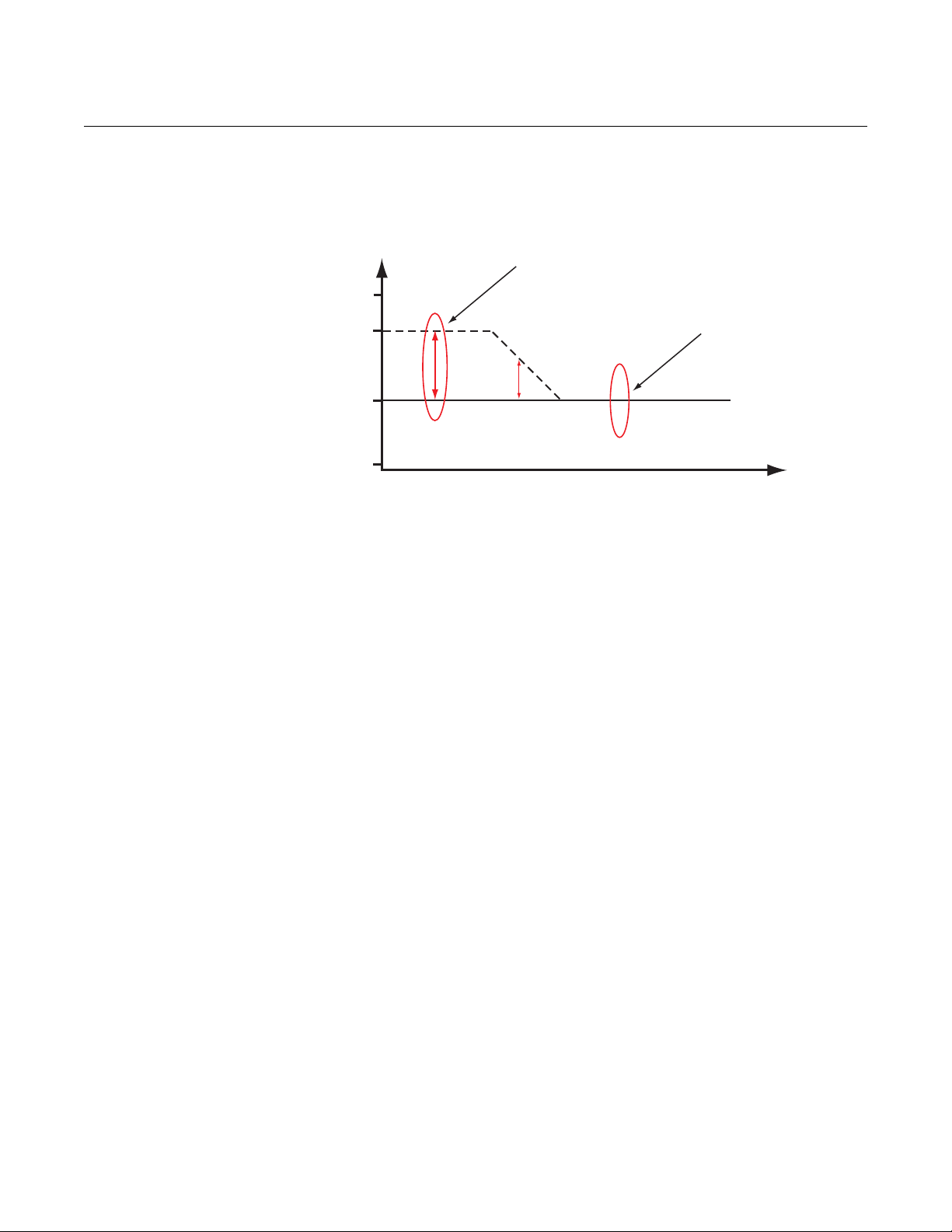
Case 1 - Level measurements
Figure 5-1. Threshold T2 too
high. Level peak not detected.
The following Threshold Setting scenarios are shown using the Waveform
Plot tool in RCT (connected to a Rosemount 3300 Series transmitter).
Threshold settings for RRM (connected to a Rosemount 5300 Series
transmitter) can be similarly configured. General guidelines for 5300 threshold
settings can be found on page 5-10.
The Product Dielectric Constant is wrong, resulting in an amplitude threshold
T2 above the actual product surface peak.
Figure 5-2. Threshold T2
lowered. Product surface P2
detected.
The Product Dielectric Constant is corrected, resulting in an amplitude
threshold T2 properly set to pick up the product surface level.
5-3
Rosemount Radar Level Transmitters
Reference Manual
00809-0600-4811, Rev AA
February 2009
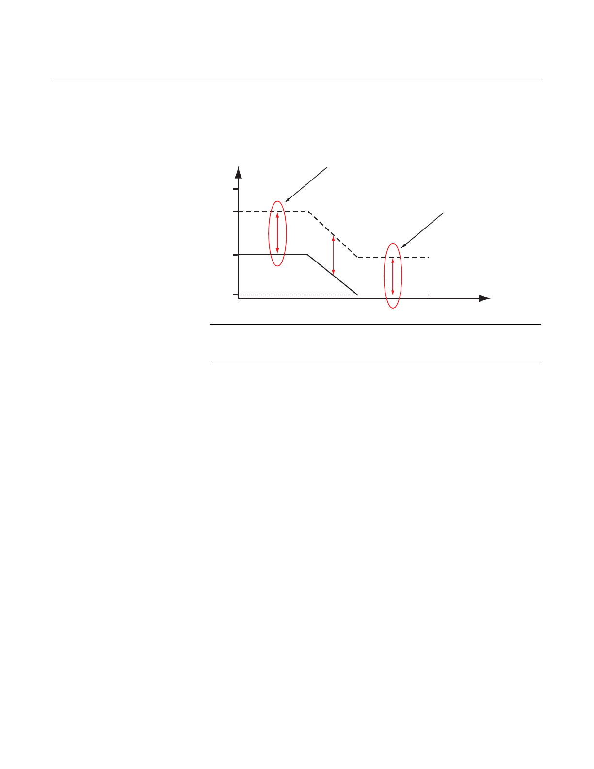
Case 2 - Level & Interface measurements
Figure 5-3. Using the wrong
Upper Product DC may result in
a threshold T2 above the
surface peak.
The wrong Upper Product Dielectric Constant is set, resulting in an amplitude
threshold T2 above the actual product surface peak. The interface peak is
incorrectly interpreted as the product surface.
Figure 5-4. Correct Upper
Product DC allows the
transmitter to detect both the
product level and the interface.
When the correct Upper Product Dielectric Constant is set, the amplitude
threshold T2 is located below the product surface level peak. Both the product
surface level and the interface level are detected.
5-4

Reference Manual
Actual product surface
UPPER NULL ZONE
Incorrect
interpretation as
product surface
Product surface
UPPER NULL ZONE
Disturbance
00809-0600-4811, Rev AA
February 2009
DISTURBANCES FROM NOZZLE
Rosemount Radar Level Transmitters
Upper Null Zone adjustment
Figure 5-5. Waveform plot
indicates that the transmitter
misinterprets a disturbing echo
as the product surface.
The transmitter identifies a disturbance from the nozzle as the product surface
(P2), as shown in Figure 5-5.
Figure 5-6. Waveform plot after
UNZ was adjusted.
To change the Upper Null Zone in RCT:
View>Device Commands>Basics>Set Null Zones.
After the Upper Null Zone (UNZ) is adjusted, the transmitter ignores the
disturbing echo and correctly shows the product surface.
5-5
Reference Manual
Incorrect
interpretation as
product surface
Actual product
surface
Product surface
00809-0600-4811, Rev AA
Rosemount Radar Level Transmitters
February 2009
Nozzle influence Installation in a rough nozzle may result in several disturbing echoes, as
illustrated in Figure 5-7.
Figure 5-7. Example of a
waveform plot for an installation
in a rough nozzle.
Figure 5-8. Typical plot for an
installation in a 4 in. (100 mm)
nozzle with a smooth interior.
With a 4-in. (100 mm) smooth nozzle that is clean on the inside, the Level and
Interface peaks are easily distinguished from noise and other disturbing
peaks.
5-6

Reference Manual
Near Zone threshold
00809-0600-4811, Rev AA
February 2009
Rosemount Radar Level Transmitters
Near Zone Threshold Disturbing echoes may result from rough edges in the nozzle. Figure 5-9
illustrates that this may cause the transmitter to identify the wrong peak as the
product surface.
If the product surface is not located as close to the nozzle as indicated in the
waveform plot, set the Near Zone Threshold. The amplitude threshold T2 can
be adjusted to filter out disturbances close to the nozzle. The adjusted
threshold T2 correctly detects the surface peak, as illustrated in Figure 5-10.
Figure 5-9. A disturbing echo
from the nozzle is erroneously
marked as the product surface.
Figure 5-10. The Near Zone
Threshold hides the disturbing
echoes.
5-7
Rosemount Radar Level Transmitters
Memory Map command
Factory CommandsFactory Only
Memory Map window
Receive button
To set the Near Zone Threshold:
1. In the RCT program Status bar, click the Factory Commands icon to
open the password input field.
2. Enter the password. The default password is “RMT”.
3. Click the Memory Map icon in the RCT project bar.
Response: the Memory Map window appears.
Figure 5-11. Near Zone
threshold is defined by distance
from reference pulse and
amplitude.
Reference Manual
00809-0600-4811, Rev AA
February 2009
5-8
4. Choose Factory Only from the memory area drop-down list. Please note
that if another drop-down item is chosen, the row number may not line up
with the Memory Map name.
5. Click the Receive button to update the Memory Map window with the
current transmitter database settings.
6. In the NearZoneEnd field enter the desired distance measured from the
Reference pulse (in the Waveform plot the x-axis zero is located on the
Reference pulse).
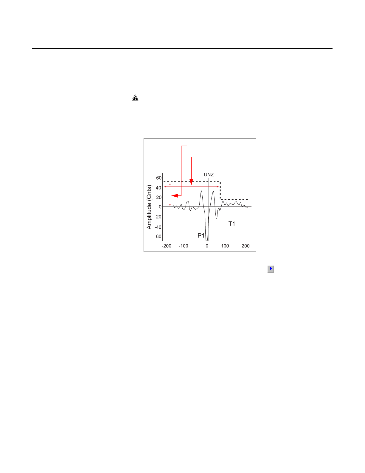
Reference Manual
NearZoneEnd
MinNearThreshSingle
00809-0600-4811, Rev AA
February 2009
Rosemount Radar Level Transmitters
7. In the MinNearThreshSingle field enter the desired threshold value.
Note that the MinNearThreshSingle parameter is used for Rigid Single
Lead and Flexible Single Lead probes only.
8. Click the Send button to forward the threshold values to the transmitter
database.
If other memory map values are changed, the transmitter may stop
working as intended. Only make changes to values as suggested in
these instructions.
9. Open the Waveform Plot to verify the threshold settings.
10. In the Waveform Plot window, click the Read
(1)
button to view the
measurement signal and the Near Zone threshold (see also “Rosemount
3300 Threshold Settings” on page 5-3).
(1) You may have to read the Waveform Plot twice in order to view the updated Near Zone
Threshold.
5-9

Rosemount Radar Level Transmitters
Reference Manual
00809-0600-4811, Rev AA
February 2009
ROSEMOUNT 5300 THRESHOLD SETTINGS
Figure 5-12. Threshold settings
in Rosemount Radar Master
(RRM).
The Rosemount 5300 measurement is based on the radar signal pulses
reflected by the product surface and the interface between two liquids.
Various signal amplitude thresholds are used to separate the measurement
signal from disturbing echoes and noise. The amplitude thresholds are
automatically set by the 5300 transmitter, and no manual settings are needed.
However, due to the properties of the product, it may be necessary to adjust
the amplitude thresholds for optimum measurement performance. The
Rosemount Radar Master (RRM) supports threshold settings in the Advanced
Configuration window:
1. Click the Advanced icon in the Device Config/Setup toolbar.
2. Select the Thresholds tab in the Advanced Configuration window.
5-10
Automatic threshold settings are enabled by default. In the Advanced
Configuration window the Interface, Reference, Probe End and Full Tank
thresholds can be set manually.
Automatic Surface Threshold
When this check-box is selected, the transmitter automatically sets the
Surface threshold to a constant value based on the configured Dielectric
Constant of the product.
Note that by enabling the Automatic Surface threshold setting, the Amplitude
Threshold Curve (ATC) is replaced by a constant threshold value.
The Surface threshold can also be set manually using the Set Threshold
function in the Echo Curve Analyzer / Configuration Mode window.
Interface Threshold
Amplitude threshold for detection of the Interface level peak.
Reference Threshold
Amplitude threshold for detection of the Reference pulse.

Reference Manual
Interface Threshold
Surface Threshold
Reference Threshold
Full Tank Threshold
Amplitude (mV)
Offset= +800 mV
Distance (m)
Reference Peak=-2000 mV
- 10%
00809-0600-4811, Rev AA
February 2009
Rosemount Radar Level Transmitters
Probe End Threshold
If the Probe End Projection function is used, this threshold may need to be
adjusted so the probe end pulse is properly detected.
Full Tank Threshold Offset
The Full Tank threshold is related to the Reference Threshold, and can detect
that the tank is full. The given offset value determines the gap between the
Reference threshold and the Full Tank threshold. The transmitter considers
the tank full when the amplitude of the Reference Peak has dropped to a
value between the two threshold values.
If the amplitude of the Reference peak is below the Full Tank Threshold
(negative amplitude of the Reference peak) the tank is not considered full.
The Full Tank Threshold Offset should be set so the Full Tank Threshold
coincides with an amplitude value equal to 90% of the Reference Echo peak
amplitude when the tank is not full.
Example
In the example below the following assumptions are made (note the negative
sign):
Figure 5-13. Example of how to
specify the Full Tank Threshold.
Reference Echo peak amplitude = -2000 mV.
Reference Threshold = -1000 mV.
The target position for the Full Tank Threshold is 10% below the Reference
Echo peak amplitude. In this example the Full Tank Threshold should be
located at 10% below the Reference peak at -2000 mV:
-2000 mV - (-200 mV)= -1800 mV.
Since the Full Tank Threshold refers to the Reference Threshold, the resulting
offset value has to be expressed in terms of the distance to the Reference
Threshold:
Full Tank Threshold Offset = -1000 mV - (-1800 mV) = +800 mV.
5-11

Reference Manual
Device Commands
Message area
Read Device Status
Tools
Diag folder
00809-0600-4811, Rev AA
Rosemount Radar Level Transmitters
February 2009
DEVICE STATUS Warnings, Errors and Device Status messages are indicated in the Radar
Configuration Tools (RCT) workspace Message area as illustrated in
Figure 4-2.
Device Status: Rosemount 3300 Series
Figure 5-14. RCT offers several
options to view device status
and error messages.
To view error messages in the Message area do one of the following:
• Click the Read Device Status icon in the toolbar at the top of the
RCT workspace
• 1. Open the Tools section in the RCT workspace Project Bar and click
the Device Commands icon, or choose the Device Commands option
from the View menu.
2. Open the folder named Diag and double-click the Read Gauge
Status option.
The different device status, error, and warning messages are listed in the
Rosemount 3300 Series Reference manual (00809-0100-4811).
5-12

Reference Manual
00809-0600-4811, Rev AA
February 2009
Rosemount Radar Level Transmitters
Device Status: Rosemount 5300 Series
Table 5-1. Device status.
Running Boot Software
Device Warning A device warning is active. See Warning Messages for details.
Device Error A device error is active. See Error Messages for details.
Simulation Mode 0 The simulation mode is active. Turn off the simulation mode.
Simulation Mode 1
Invalid Measurement The level measurement is invalid.
User Register Area Write
Protected
Write Protected Jumper Set
Factory Settings Used
Probe missing Probe is not detected.
Device Status messages that may appear on the Integral Display, on the 375
Field Communicator, or in the Rosemount Radar Master (RRM) program are
shown in Table 5-1:
Message Description Action
The application software could not be
started.
The advanced simulation mode is
active.
The configuration registers are write
protected.
Write protection jumper on the display
is enabled.
The factory default configuration is
used.
Contact Emerson Process
Management Service Department.
To turn off the Advanced Simulation
mode, set Holding Register 3600=0.
Check Error Messages, Warning
Messages and Measurement Status
for details.
Use the Lock / Unlock function to turn
off the write protection.
Remove the write protection jumper.
The transmitter has lost its calibration.
Contact Emerson Process
Management Service Department.
Check that the probe is correctly
mounted. Check the connection
between probe and transmitter head.
5-13

Rosemount Radar Level Transmitters
Reference Manual
00809-0600-4811, Rev AA
February 2009
5-14

Reference Manual
00809-0600-4811, Rev AA
February 2009
Rosemount Radar Level Transmitters
Section 6 Verification Procedure
Introduction . . . . . . . . . . . . . . . . . . . . . . . . . . . . . . . . . . . . . page 6-1
Verification Procedure . . . . . . . . . . . . . . . . . . . . . . . . . . . . page 6-2
Diagnostics . . . . . . . . . . . . . . . . . . . . . . . . . . . . . . . . . . . . . page 6-5
INTRODUCTION Once a Rosemount 3300 / 5300 transmitter is installed and configured, it will
continuously deliver measurement data with a minimum of maintenance.
Transmitter performance should be verified on a regular basis to ensure
proper function.
• Configure and commission the transmitter as described in this
document and the Rosemount 3300 / 5300 Series Reference Manuals
(Document No. 00809-0100-4811 and 00809-0100-4530)
• If needed, adjust threshold settings, Upper Null Zone settings, Trim
Near Zone, or mechanical nozzle adjustments
• When using the 3300 Series, run the Self Test function to verify there
are no transmitter hardware or software errors. The 5300 Series
automatically performs a self test
• View and save a waveform plot for the configured transmitter. A plot
function is available in the Radar Configuration Tools (RCT) for the
3300 Series, and in the Rosemount Radar Master (RRM) software for
the 5300 Series. The plot is used as a baseline for future reference
when verifying the transmitter
• For the 5300 Series, additional diagnostics capabilities eliminate the
need for verification self-tests. The following information can be
retrieved about the device:
- device status
- device errors
- device warnings
- measurement status
- volume status
- analog output status
www.rosemount.com
For more information, see section Service and Troubleshooting in the
High Performance Guided Wave Radar, Rosemount 5300 Series
Reference Manual (Document No. 00809-0100-4530).

Rosemount Radar Level Transmitters
Device CommandsDevice Commands
Self Test
Too ls
Reference Manual
00809-0600-4811, Rev AA
February 2009
VERIFICATION PROCEDURE
The Rosemount 3300 transmitter is equipped with diagnostic tools which
facilitate verification of measurement performance. The verification procedure
should include a transmitter self test and an inspection of the waveform plot
described below.
Self Test The built-in self test function is available in the RCT program. To run the self
test:
1. Open the Tools section in the RCT workspace Project Bar.
2. Click the Device Commands icon, or choose the Device Commands
option from the View menu.
3. Open the Diag folder and double-click the Self Test option.
4. Verify that the Self Test result is successful.
Figure 6-1. Use the Self Test
function to verify that no
hardware errors occur.
6-2
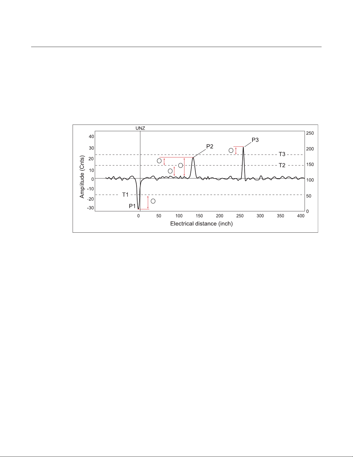
Reference Manual
1
2
3
4
5
00809-0600-4811, Rev AA
February 2009
Rosemount Radar Level Transmitters
Rosemount 3300 Plot Verification
Figure 6-2. Rosemount 3300:
Mesurement conditions can be
analyzed by using the Waveform
Plot.
To verify the Rosemount 3300 level measurement, read a waveform plot and
save it on a disk. Open the original plot from the original transmitter
commissioning and compare it to the new plot. Use the check list below to
verify sufficient signal/noise ratio and proper amplitude threshold values.
1. Check the Reference pulse amplitude and position.
Ensure that the margin to T1 is sufficient. If the Reference pulse
amplitude peak is above the threshold T1, the transmitter will report “Full
Ta nk ” .
2. Check the noise amplitude versus threshold T2.
The noise level may increase when the probe is coated, reducing the
margin to surface threshold T2. An insufficient margin may lead to the
wrong peak being interpreted as the product surface.
3. Check the margin between signal peak P2 and surface threshold T2.
Robust measurement is achieved from having a margin that allows minor
amplitude fluctuations because of a turbulent product surface or coated
probe. Failure to detect the product surface, or the wrong peak being
interpreted as the product surface may be from a margin that does not
allow minor amplitude fluctuations.
4. Check the signal/noise ratio, i.e. the maximum noise amplitude/peak
amplitude P2.
An incorrect ratio may cause failure to detect the product surface, or the
wrong peak being interpreted as the product surface.
5. Check the margin between interface peak P3 and amplitude threshold
T3.
If the margin is incorrect, it may lead to failure.
6-3

Rosemount Radar Level Transmitters
Reference Manual
00809-0600-4811, Rev AA
February 2009
Rosemount 5300 Plot Verification
Recommendations for the Rosemount 5300 Series:
1. Use of the automatic threshold settings ensures that the dielectric
constants of the upper and lower products have been entered correctly.
2. If needed, apply the Measure and Learn function.
3. Use the following best practices to apply custom threshold adjustments,
if necessary:
• Generally, the threshold should be at 40-50% of the surface peak.
Example: If the surface is 2000 mV, the threshold should be set at
800-1000 mV
• The threshold should never be closer than 300 mV to a disturbing
object. Example: If there is a 1100 mV peak from an inlet pipe, the
threshold around it should be 1400 mV
The threshold should never be below 800 mV in the range 0-1 ft. (0.3 m) and
never below 500 mV from ranges above 1 ft. (0.3 m).
For products with very low dielectric constants, such as solids, it may be
necessary to lower the threshold.
6-4
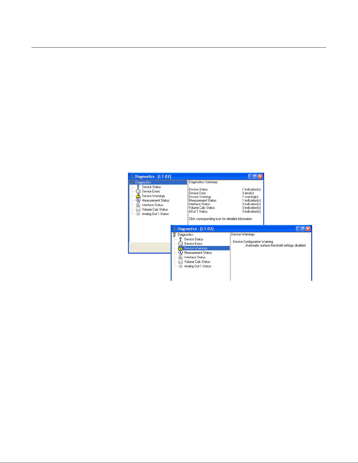
Reference Manual
00809-0600-4811, Rev AA
February 2009
Rosemount Radar Level Transmitters
DIAGNOSTICS The following information is available in the referred subsections of Service
and Troubleshooting in the Rosemount 5300 Series Reference Manual
(Document No. 00809-0100-4530):
• device status, see “Device Status”
• device errors, see “Errors”
• device warnings, see “Warnings”
• measurement status, see “Measurement Status”
• volume status, see “Volume Calculation Status”
• analog output status, see “Analog Output Status”
Rosemount Radar Master
To open the Diagnostics window in RRM, choose the Diagnostics option
from the Tools menu:
Figure 6-3. The Diagnostics
window in Rosemount Radar
Master.
HART command
For a 375 Field Communicator the corresponding HART command for the
Diagnostics option is [3, 1].
6-5

Rosemount Radar Level Transmitters
Reference Manual
00809-0600-4811, Rev AA
February 2009
6-6

Reference Manual
00809-0600-4811, Rev AA
February 2009
Rosemount Radar Level Transmitters
Appendix A Model Code Information
Model Code 3302 and 5302, Level and Interface in Liquids . . . page A-2
This is a summary of the Rosemount 3300 / 5300 model codes, adapted to
the applications described in the previous sections of this document. The
complete model code for the Rosemount 3300 / 5300 Series is available in
the following documents:
• Rosemount 3300 Series Reference Manual
(Document No. 00809-0100-4811)
• Rosemount 3300 Series Product Data Sheet
(Document No. 00813-0100-4811)
• Rosemount 5300 Series Reference Manual
(Document No. 00809-0100-4530)
• Rosemount 5300 Series Product Data Sheet
(Document No. 00813-0100-4530)
www.rosemount.com

Rosemount Radar Level Transmitters
MODEL CODE 3302 AND 5302, LEVEL AND INTERFACE IN LIQUIDS
Model Product Description
3302 Guided Wave Radar Level and Interface Transmitter
5302 Guided Wave Radar Liquid Level and Interface Transmitter
Code Signal Output
H 4-20 mA with HART® communication
M RS-485 with Modbus communication
F FOUNDATION™ fieldbus (Rosemount 5300 Series only)
Code Housing Material
A Polyurethane-covered Aluminum
Code Conduit / Cable Threads
1 ½ - 14 NPT
Code Operating Temperature and Pressure
S - 15 psig (-1bar) to 580 psig (40 bar) @ 302 °F (150 °C) All
(3)
High Pressure
P
Code Material of Construction
1 316 / 316 L SST (EN 1.4404) All
Code Sealing, O-ring Material (Consult factory for other o-ring materials)
N None
V Viton® fluoroelastomer
E Ethylene Propylene
Code Probe Type Process Connection Probe Lengths
4A Rigid Single Lead Flange, 1
5A Flexible Single Lead with weight Flange, 1
5B Flexible Single Lead with chuck
Code Probe Length Units
E English (feet, in.)
M Metric (meters, centimeters)
Max 392 °F (200 °C): 3500 psi @ 392 °F and 5000 psi @ 100 °F (243 bar
@ 200 °C and 345 bar @ 38 °C) according to ANSI Class 2500
(5)
:
(4)
: Process Connection / Probe Probe Type
(1)
(2)
(6)
or 1.5 in. Thread Min: 1 ft 4 in. (0.4 m). Max: 9 ft 10 in. (3 m)
(6)
or 1.5 in. Thread Min: 3 ft 4 in. (1 m). Max: 164 ft (50 m)
(7)
Flange, 1
(6)
or 1.5 in. Thread Min: 3 ft 4 in. (1 m). Max: 164 ft (50 m)
Probe Type
3A, 3B, 4A, 5A and 5B (only SST)
Reference Manual
00809-0600-4811, Rev AA
February 2009
A-2

Reference Manual
00809-0600-4811, Rev AA
February 2009
Rosemount Radar Level Transmitters
Code Total Probe Length
xxx
Code Total Probe Length
xx 0-11 in. or 0-99 cm
Code Process Connection - Size / Type (consult factory for other process connections)
ANSI Flanges in 316L SST (EN 1.4404)
AA 2 in. ANSI, 150 lb
AB 2 in. ANSI, 300 lb
AC 2 in. ANSI, 600 lb. HTHP / HP units
AD 2 in. ANSI, 900 lb. HTHP / HP units
AE 2 in. ANSI, 1500 lb. HTHP / HP units
AI 2 in. ANSI, 600 lb, RTJ (Ring Type Joint). HTHP / HP units
AJ 2 in. ANSI, 900 lb, RTJ (Ring Type Joint). HTHP / HP units
AK 2 in. ANSI, 1500 lb, RTJ (Ring Type Joint). HTHP / HP units
BA 3 in. ANSI, 150 lb
BB 3 in. ANSI, 300 lb
BC 3 in. ANSI, 600 lb. HTHP / HP units
BD 3 in. ANSI, 900 lb. HTHP / HP units
BE 3 in. ANSI, 1500 lb. HTHP / HP units
BI 3 in. ANSI, 600 lb, RTJ (Ring Type Joint). HTHP / HP units
BJ 3 in. ANSI, 900 lb, RTJ (Ring Type Joint). HTHP / HP units
BK 3 in. ANSI, 1500 lb, RTJ (Ring Type Joint). HTHP / HP units
CA 4 in. ANSI, 150 lb
CB 4 in. ANSI, 300 lb
CC 4 in. ANSI, 600 lb. HTHP / HP units
CD 4 in. ANSI, 900 lb. HTHP / HP units
CE 4 in. ANSI, 1500 lb. HTHP / HP units
CI 4 in. ANSI, 600 lb, RTJ (Ring Type Joint). HTHP / HP units
CJ 4 in. ANSI, 900 lb, RTJ (Ring Type Joint). HTHP / HP units
CK 4 in. ANSI, 1500 lb, RTJ (Ring Type Joint). HTHP / HP units
DA 6 in. ANSI, 150 lb
0-164 ft. or 0-50 m (Code xxx for the 5300 Series only. Code xx for the 3300 Series with ranges 0-77 ft. or 0-23 m.)
(8)
(feet/m)
(8)
(in./cm)
A-3
Reference Manual
00809-0600-4811, Rev AA
Rosemount Radar Level Transmitters
Code Process Connection - Size / Type (consult factory for other process connections)
Threaded Connections Probe Type
RA 1 ½ in. NPT thread All
RB 1 in. NPT thread
Code Hazardous Locations Certifications
E5 FM Explosion-proof
Code Options
M1 Integral digital display
LS
T1
Long stud
Standard height is 3.9 in. (100 mm) for probes 5A and 5B.
Transient Protection Terminal Block (5300 Series only. Defaulted for the 3300 Series, so no T1 option needed.)
(9)
9.8 in. (250 mm) for flexible single lead probe to prevent contact with wall/nozzle.
Sx and Px - Centering Discs Outer Diameter
S2 2 in. Centering disc SST
S3 3 in. Centering disc SST
S4 4 in. Centering disc SST
P2 2 in. Centering disc PTFE
P3 3 in. Centering disc PTFE
P4 4 in. Centering disc PTFE
(10)
(10)
(10)
(11)
(11)
(11)
Cx - Special Configuration (Software)
C1 Factory configuration (CDS required with order)
C8 Low alarm
(12)
(standard Rosemount alarm and saturation levels)
Qx - Special Certifications
Q4 Calibration Data Certification
Q8 Material Traceability Certification per EN 10204 3.1
(1) Requires external 8-30 Vdc power supply.
(2) Process seal rating. Final rating depends on flange and O-ring selection.
(3) Requires option None for sealing (no O-ring). Only for SST (“Material of Construction, Code 1).
(4) For other materials, consult factory.
(5) Requires High Temperature High Pressure (code H) or High Pressure (Code P) probe.
(6) Only available with standard temperature and pressure (Code S).
(7) Extra length for fastening is added in factory.
(8) Probe weight included, if applicable. Give the total probe length in feet and inches or meters and centimeters, depending on selected probe length unit.
If tank height is unknown, round up to an even length when ordering, because probes can be cut to exact length in the field. The maximum allowable length
is determined by process conditions.
(9) Not available with PTFE covered probes.
(10) Available for SST probes, type 2A, 4A and 5A.
(11) Available for SST probes, type 2A, 4A and 5A, except for HTHP.
(12) The standard alarm setting is high.
(13) Certificate includes all pressure retaining wetted parts.
(13)
3A, 3B, 4A, 5A, 5B, standard temperature and
pressure
1.8 in. (45 mm)
2.7 in. (68 mm)
3.6 in. (92 mm)
1.8 in. (45 mm)
2.7 in. (68 mm)
3.6 in. (92 mm)
February 2009
A-4
Reference Manual
00809-0600-4811, Rev AA
February 2009
Rosemount Radar Level Transmitters
Model Code Example - Rosemount 3300 Series
3302 H A 1 P 1 N 4A E 05 11 CA E5 M1 S4
Application: 6 ft chamber on high pressure vertical separator tank; requires interface only
H 4-20 mA with HART
A Aluminum housing
1 ½ - 14 NPT conduit
High Pressure:
P
1 Material of construction: 316 / 316 L SST (EN 1.4404)
N None
4A Rigid Single Lead probe
E English (feet, in.)
05
11
CA 4 in. ANSI, 150 lb flange
E5 FM Explosion-proof
M1 Integral digital display
S4 4 in. Centering disc SST; Outer Diameter: 3.6 in. (92 mm)
Max. 392 °F (200 °C): 3500 psi @ 392 °F and 5000 psi @ 100 °F (243 bar
@ 200 °C and 345 bar @ 38 °C) according to ANSI Class 2500
5 ft and 11 in. probe
communication
Model Code Example - Rosemount 5300 Series
5302 H A 1 S 1 V 5A E 011 06 CA E5 M1 T1
Application: Fiberglass storage tank approx. 11 1/2 ft; Both level and level / interface½½
H 4-20 mA with HART communication
A Aluminum housing
1 ½ - 14 NPT conduit
S Operating Temperature: -15 psig (-1 bar) to 580 psig (40 bar) @ 302 °F (150 °C)
1 Material of construction: 316 / 316 L SST (EN 1.4404)
V Viton® fluoroelastomer seal
5A Flexible Single Lead probe
E English (feet, in.)
011
06
CA 4 in. ANSI, 150 lb flange
E5 FM Explosion-proof
M1 Integral digital display
T1
11 ft and 6 in. probe
Transient Protection Terminal Block
A-5

Rosemount Radar Level Transmitters
Reference Manual
00809-0600-4811, Rev AA
February 2009
A-6


Reference Manual
00809-0600-4811, Rev AA
February 2009
Rosemount Radar Level Transmitters
Standard Terms and Conditions of Sale can be found at www.rosemount.com\terms_of_sale.
The Emerson logo is a trademark and service mark of Emerson Electric Co.
Rosemount and the Rosemount logotype are registered trademarks of Rosemount Inc.
HART is a registered trademark of the HART Communication Foundation.
Modbus is a registered trademark of Modicon.
PlantWeb is a registered trademark of one of the Emerson Process Management group of companies.
Teflon, VITON, and Kalrez are registered trademarks of DuPont Performance Elastomers.
Asset Management Solutions is a trademark of Emerson Process Management.
All other marks are the property of their respective owners.
© 2009 Rosemount Inc. All rights reserved.
Emerson Process Management
Rosemount Measurement
8200 Market Boulevard
Chanhassen MN 55317 USA
Tel (USA) 1 800 999 9307
Tel (International) +1 952 906 8888
Fax +1 952 949 7001
00809-0600-4811 Rev AA, 02/09
Emerson Process Management
Blegistrasse 23
P.O. Box 1046
CH 6341 Baar
Switzerland
Tel +41 (0) 41 768 6111
Fax +41 (0) 41 768 6300
Emerson FZE
P.O. Box 17033
Jebel Ali Free Zone
Dubai UAE
Tel +971 4 811 8100
Fax +971 4 886 5465
Emerson Process Management Asia
Pacific Pte Ltd
1 Pandan Crescent
Singapore 128461
Tel +65 6777 8211
Fax +65 6777-0947
Service Support Hotline: +65 6770 8711
Email: Enquiries@AP.EmersonProcess.com
Loading...