

Rosemount Guide: Display Unit RDU 40 User´s Guide-TankRadar Rex | Rosemount Manuals & Guides

User’s Guide
308010EN, Edition 2
July 2007
Display Unit RDU 40
www.rosemount-tg.com

Display Unit RDU 40
User´s Guide
Second edition
Copyright
Rosemount Tank Radar AB
© July 2007
www.rosemount-tg.com

Copyright © July 2007
Rosemount Tank Radar AB
The contents, descriptions and specifications within this manual is
subject to change without notice. Rosemount Tank Radar AB accepts no
responsibility for any errors that may appear in this manual.
Trademarks
Rosemount, and the Rosemount logotype are registered trademarks of
Rosemount Inc.
TankRadar is a registered trademark of Rosemount Tank Radar AB.
HART is a registered trademark of HART Communication Foundation
Modbus is a registered trademark of Modicon.
Pentium is a registered trademark of Intel Corporation.
Windows NT is trademark of Microsoft Corporation.
Viton is a registered trademark of Du Pont Performance Elastomers.
Spare Parts
Any substitution of non-recognized spare parts may jeopardize safety.
Repair, e.g. substitution of components etc, may also jeopardize safety
and is under no circumstances allowed.
Rosemount Tank Radar AB will not take any responsibility for faults,
accidents, etc caused by non-recognized spare parts or any repair which
is not made by Rosemount Tank Radar AB.
Specific FCC Requirements (USA only)
Rosemount TankRadar REX generates and uses radio frequency
energy. If it is not installed and used properly, that is, in strict accordance
with the manufacturer´s instructions, it may violate FCC regulations on
radio frequency emission.
Rosemount TankRadar REX has been FCC certified under test
conditions which assume a metallic tank. Installation on a non-metallic
tank is not certified, and is not allowed.
The FCC certificate for Rosemount TankRadar REX requires that the
tank is closed as far as emitted radio energy is concerned. Tanks with
open manholes, external-floating-roof tanks without still pipes etc. are
not covered by the certificate.
www.rosemount-tg.com

User’s Guide
308010EN, Edition 2
July 2007
Rosemount TankRadar REX
Contents
Contents
1. INSTALLATION . . . . . . . . . . . . . . . . . . . . . . . . . . . . . . . . 1-1
1.1 TWO RDU40 CONNECTED TO THE SAME REX . . . . . . . . . . . . . . . .1-2
2. DEVICE HANDLING . . . . . . . . . . . . . . . . . . . . . . . . . . . . . 2-1
2.1 OPERATION . . . . . . . . . . . . . . . . . . . . . . . . . . . . . . . . . . . . . . . . . . . . .2-1
2.1.1 User defined view . . . . . . . . . . . . . . . . . . . . . . . . . . . . . . .2-2
2.1.2 Single value view . . . . . . . . . . . . . . . . . . . . . . . . . . . . . . .2-2
2.1.3 Standard view . . . . . . . . . . . . . . . . . . . . . . . . . . . . . . . . . .2-2
2.2 SERVICE MENU . . . . . . . . . . . . . . . . . . . . . . . . . . . . . . . . . . . . . . . . .2-2
2.3 SETUP DISPLAY FOR USER DEFINED VIEW . . . . . . . . . . . . . . . . . .2-3
2.3.1 Standard view . . . . . . . . . . . . . . . . . . . . . . . . . . . . . . . . . .2-4
2.3.2 Toggling view . . . . . . . . . . . . . . . . . . . . . . . . . . . . . . . . . .2-4
2.3.3 Two rows view . . . . . . . . . . . . . . . . . . . . . . . . . . . . . . . . .2-5
2.4 DISPLAY SETUP BY USING WINSETUP . . . . . . . . . . . . . . . . . . . . . .2-5
2.4.1 User defined view . . . . . . . . . . . . . . . . . . . . . . . . . . . . . . .2-7
2.4.2 The single value view . . . . . . . . . . . . . . . . . . . . . . . . . . . . 2-9
2.4.3 Set timeout for return to default display . . . . . . . . . . . . . .2-9
2.5 CHANGE PASSWORD . . . . . . . . . . . . . . . . . . . . . . . . . . . . . . . . . . . . .2-9
3. TROUBLESHOOTING . . . . . . . . . . . . . . . . . . . . . . . . . . . . 3-1
3.1 THE RDU40 FLASHES A CHECKERED PATTERN. . . . . . . . . . . . . . .3-1
3.2 RDU40 LCD PROBLEM. . . . . . . . . . . . . . . . . . . . . . . . . . . . . . . . . . . .3-2
3.3 RDU40 DOES NOT RESPOND. . . . . . . . . . . . . . . . . . . . . . . . . . . . . .3-2
3.4 LIMITED FUNCTIONALITY OF RDU40. . . . . . . . . . . . . . . . . . . . . . . .3-2
TOC-1

Rosemount TankRadar REX
Contents
User’s Guide
308010EN, Edition 2
July 2007
TOC-2
User’s Guide
308010EN, Edition 2
July 2007
1. Installation
Remove the rubber plug for access to the upper screw of the RDU40
cover. Unscrew and remove all six screws. Remove the cover and take
care of the locking device for the weather protection hatch.
The RDU40 shall be connected to the TankRadarREX junction box for
cable connections.
Rosemount Tank Radar REX
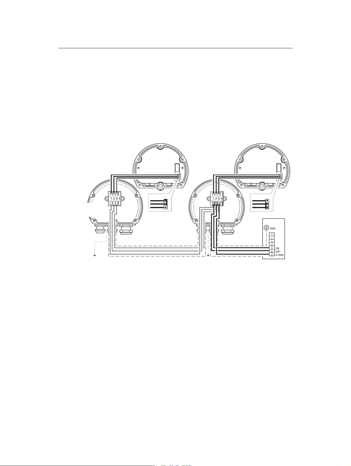
Chapter 1 Installation
RDU 40
Slave (optional)
Cover/
Display
Jumper Position 2
RDU 40
Master
Cover/
Display
Jumper Position 1
Figure 1-1. Installation of RDU40 master and slave.
Any of the three cable glands may be used to take the cable into the
RDU40:
• 2xM20 – Cable diameter min 7 mm, max 14 mm.
• 1xM25 – Cable diameter min 9 mm, max 18 mm.
External adapters 1/2 NPT and 3/4 NPT are optional.
Connect the RDU40 to the X12 terminal (also marked ”Exi”) in the REX
junction box as described in picture 1. Requirements for the cable
between the RDU40 and the REX junction box to fulfill performance
regarding functionality and EMC are:
• Shielded cable. Minimum 3 wires. The shield shall be circular connected inside the cable gland of the RDU40 and connected to
ground in the REX junction box.
• All wires must have at least 0.25 mm individual insulation.
• Maximum total length of 100 m, both master and slave included.
2
• Minimum AWG 20 or 0.5 mm
for each wire.
1-1
 Loading...