

Page 1

Reference Manual
00809-0100-3412, Rev AA
Rosemount™ FCL
Free Chlorine System with Rosemount 1056 Transmitter
May 2019
Page 2

Essential instructions
Read this page before proceeding!
Emerson designs, manufactures, and tests its products to meet many national and international standards. Because these
instruments are sophisticated technical products, you must properly install, use, and maintain them to ensure they continue to
operate within their normal specifications. The following instructions must be adhered to and integrated into your safety program
when installing, using, and maintaining Emerson products. Failure to follow the proper instructions may cause any one of the
following situations to occur: loss of life, personal injury, property damage, damage to this instrument, and warranty invalidation.
• Read all instructions prior to installing, operating, and servicing the product.
• If this Reference Manual is not the correct one, call 1-800-999-9307 to request the correct Reference Manual. Save this
Reference Manual for future reference.
• If you do not understand any of the instructions, contact your Emerson representative for clarification.
• Follow all warnings, cautions, and instructions marked on and supplied with the product.
• Inform and educate your personnel in the proper installation, operation, and maintenance of the product.
• Install equipment as specified in the installation instructions of the appropriate Reference Manual and per applicable local and
national codes. Connect all products to the proper electrical and pressure sources.
• To ensure proper performance, use qualified personnel to install, operate, update, program, and maintain the product.
• When replacement parts are required, ensure that qualified people use replacement parts specified by Rosemount.
Unauthorized parts and procedures can affect the product's performance, place the safe operation of your process at risk, and
may result in fire, electrical hazards, or improper operation.
• Ensure that all equipment doors are closed and protective covers are in place, except when maintenance is being performed
by qualified people, to prevent electrical shock and personal injury.
WARNING
Hazardous area installation
Installations near flammable liquids or in hazardous area locations must be carefully evaluated by qualified on site safety
personnel. This device is not Intrinisically Safe or Explosion Proof.
To secure and maintain intrinsically safe installation, use an appropriate transmitter/safety barrier/sensor combination. The
installation system must be in accordance with the governing approval agency (FM, CSA, or BASEEFA/CENELEC) hazardous
are classification requirements. Consult your transmitter Reference Manual for details.
Proper installation, operation, and servicing of this sensor in a hazardous area installation are entirely the operator's
responsibility.
2
Page 3

WARNING
Electrical shock
Making cable connections to and servicing this instrument require access to shock hazard level voltages, which can cause death
or serious injury.
Equipment protected throughout by double insulation.
Be sure to disconnect all hazardous voltages before opening the enclosure.
Disconnect relay contacts made to separate power sources before servicing.
Electrical installation must be in accordance with the National Electrical Code (ANSI/NFPA-70) and/or any other national or
local codes.
Unused cable conduit entries must be securely sealed by non-flammable closures to provide exposure integrity in
compliance with personal safety and environmental protection requirements. Unused conduit openings must be sealed
with NEMA 4X or IP65 conduit plugs to maintain the ingress protection rating (IP65).
Safety and performance require that this instrument be connected and properly grounded through a three-wire power
source.
Proper use and configuration is the operator's responsibility.
No external power to the instrument of more than 69 Vdc or 43 V peak is allowed, with the exception of power and relay
terminals. Any violation will impair the safety protection provided.
Do not operate this instrument without the front cover secured. Refer installation, operation, and servicing to qualified
personnel.
WARNING
This product is not intended for use in the light industrial, residential, or commercial environments per the instrument's
certification to EN50081-2.
CAUTION
Sensor/process application compatibility
The wetted sensor materials may not be compatible with process composition and operating conditions.
Application compatibility is entirely the operator's responsibility.
WARNING
Physical access
Unauthorized personnel may potentially cause significant damage to and/or misconfiguration of end users’ equipment. This
could be intentional or unintentional and needs to be protected against.
Physical security is an important part of any security program and fundamental to protecting your system. Restrict physical
access by unauthorized personnel to protect end users’ assets. This is true for all systems used within the facility.
3
Page 4

4
Page 5

Reference Manual Contents
00809-0100-3412 May 2019
Contents
Chapter 1 Description and specifications........................................................................................7
1.1 Specifications................................................................................................................................... 7
1.2 Ordering information....................................................................................................................... 8
Chapter 2 Install...........................................................................................................................11
2.1 Unpack and inspect........................................................................................................................ 11
2.2 General installation information..................................................................................................... 11
2.3 Sample requirements..................................................................................................................... 12
2.4 Mounting, inlet, and drain connections.......................................................................................... 12
2.5 Install the sensor(s).........................................................................................................................15
Chapter 3 Wire............................................................................................................................ 19
3.1 Wire power.....................................................................................................................................19
3.2 Wire analog outputs.......................................................................................................................19
3.3 Alarm wiring...................................................................................................................................20
3.4 Wire sensor.................................................................................................................................... 22
3.5 Quick Start..................................................................................................................................... 23
Chapter 4 Display and operation.................................................................................................. 29
4.1 Display........................................................................................................................................... 29
4.2 Keypad........................................................................................................................................... 30
4.3 Program the transmitter.................................................................................................................32
4.4 Security.......................................................................................................................................... 34
4.5 Using hold...................................................................................................................................... 35
4.6 Configure the main display.............................................................................................................36
Chapter 5 Programming the transmitter......................................................................................39
5.1 Programming overview.................................................................................................................. 39
5.2 Default settings.............................................................................................................................. 39
5.3 Configuring, ranging, and simulating outputs................................................................................ 42
5.4 Configuring alarms and assigning setpoints....................................................................................46
5.5 Configuring the measurement....................................................................................................... 53
5.6 Configuring temperature related settings...................................................................................... 56
5.7 Configuring security settings..........................................................................................................58
5.8 Set up diagnostics.......................................................................................................................... 60
5.9 Resetting the transmitter............................................................................................................... 61
Chapter 6 Calibrate...................................................................................................................... 63
6.1 Introduction................................................................................................................................... 63
6.2 Calibrate temperature.................................................................................................................... 63
6.3 Calibration - free chlorine............................................................................................................... 64
6.4 Calibration - pH.............................................................................................................................. 69
Rosemount FCL 1056 v
Page 6

Contents Reference Manual
May 2019 00809-0100-3412
6.5 Calibration - analog outputs........................................................................................................... 73
Chapter 7 Digital communications............................................................................................... 75
Chapter 8 Maintenance................................................................................................................77
8.1 Replace sensor circuit board........................................................................................................... 77
8.2 Chlorine sensor...............................................................................................................................78
8.3 pH sensor....................................................................................................................................... 81
8.4 Constant head flow controller........................................................................................................ 81
Chapter 9 Troubleshoot............................................................................................................... 85
9.1 Overview........................................................................................................................................ 85
9.2 Use the diagnostic feature..............................................................................................................85
9.3 Troubleshooting when a Fault message is showing.........................................................................86
9.4 Troubleshooting when a Warning message is showing...................................................................91
9.5 Troubleshooting when no error message is showing...................................................................... 93
9.6 Troubleshooting when no error message is showing - pH............................................................... 97
9.7 Troubleshooting when no error message is showing - general......................................................101
9.8 Simulate inputs - chlorine............................................................................................................. 102
9.9 Simulate pH input.........................................................................................................................103
9.10 Simulating temperature............................................................................................................. 104
vi Emerson.com/Rosemount
Page 7

Reference Manual Description and specifications
00809-0100-3412 May 2019
1 Description and specifications
1.1 Specifications
Rosemount™ 1056 Transmitter
For Rosemount 1056 Transmitter specifications, see the Rosemount 1056 Transmitter
Reference Manual on Emerson.com/Rosemount: Manual: Rosemount 1056 Dual-Input
Transmitter.
Table 1-1: General Specifications
Characteristic Specification
Sample requirements • Pressure: 3 to 65 psig (122 to 549 kPa abs). A
check valve in the inlet prevents the sensor
flow cells from going dry if sample flow is
lost. The check valve opens at 3 psig (122
kPa abs). If the check valve is removed,
minimum pressure is 1 psig (108 kPa abs).
• Temperature: 32 to 122 °F (0 to 50 °C)
• Minimum flow: 3 gal/hr (11 L/hr)
• Maximum flow: 80 gal/hr (303 L/hr); high
flow causes the overflow tube to back up.
Sample conductivity >50 µS/cm at 77 °F (25 °C)
Process connection ¼-in. OD tubing compression fitting (can be
removed and replaced with barbed fitting for
soft tubing)
Drain connection ¾-in. barbed fitting. Sample must drain to open
atmosphere.
Wetted parts Overflow sampler and flow cell: acrylic,
polycarbonate, Kynar®, nylon, and silicone
Chlorine sensor: Noryl®, Viton®, wood, silicone,
polyethersulfone, polyester, and platinum
pH sensor (Rosemount™ 3900VP): Stainless
steel, glass, Teflon®, polyphenylene sulfide,
EPDM, and silicone
Response time to step change in chlorine
concentration
Weight/shipping weight (rounded up to nearest
1 lb. or 0.5 kg)
< 80 sec to 95% of final reading for inlet sample
flow of 3 gph (11 L/hr)
Rosemount FCL-01: 10 lb./13 lb. (4.5 kg/6.0 kg)
Rosemount FCL-02: 11 lb./14 lb. (5.0 kg/6.5 kg)
Table 1-2: Sensor Specifications
Characteristic Specification
Free chlorine range 0 to 10 ppm as Cl2. For higher ranges, consult
the factory.
Rosemount FCL 1056 7
Page 8

Description and specifications Reference Manual
May 2019 00809-0100-3412
Table 1-2: Sensor Specifications (continued)
Characteristic Specification
pH correction range 6.0 to 9.5. For samples having pH between 9.5
and 10.0, consult the factory. If pH <6.0,
correction is not necessary. For manual pH
correction, choose option -01. For continuous
pH correction, choose option -02.
Accuracy Accuracy depends on the accuracy of the
chemical test used to calibrate the sensor.
Interferences Monochloramine, permangante, and peroxides
Electrolyte volume 25 mL (approx.)
Electrolyte life 3 months (approx.); for best results, replace
electrolyte monthly.
1.2 Ordering information
The Rosemount™ FCL is a system used for measuring free chlorine in aqueous samples.
This complete system consists of a free chlorine sensor (pH sensor optional), a transmitter,
and a constant head overflow device to control sample flow. All components are mounted
on a backplate. The factory ships three replacement membranes and a 4 oz. (118 mL)
bottle of electrolyte solution with the system.
Free Chlorine System
Table 1-3: Free Chlorine System
Code Measurement option
01 Without pH sensor
02 With pH sensor
Code Transmitter option
220 Rosemount 1056-03-24-38-AN, 115/230 Vac 50/60 Hz, alarm relays, analog outputs,
chlorine only (option -01 only)
221 Rosemount 1056-03-24-32-AN 115/230 Vac 50/60 Hz, alarm relays, analog outputs,
chlorine and pH (option -02 only)
Typical model number: FCL-01-220
Component parts
Table 1-4: Transmitter
Transmitter model Description
1056-03-24-38-AN Rosemount 1056-03-24-38-AN, 115/230 Vac 50/60 Hz, alarm relays,
analog outputs, chlorine only
1056-03-24-32-AN Rosemount 1056-03-24-32-AN, 115/230 Vac 50/60 Hz, alarm relays,
analog outputs, chlorine and pH
8 Emerson.com/Rosemount
Page 9

Reference Manual Description and specifications
00809-0100-3412 May 2019
Table 1-5: Sensor
Sensor model Description
499ACL-01-54-VP Free chlorine sensor with Variopol connector
3900VP-02-10 pH sensor with Variopol connector
Table 1-6: Cable
Sensor cable Description
23747-04 Interconnecting cable, Variopol for Rosemount 499ACL sensor, 4 ft. (1.2
m)
24281-05 Interconnecting cable, Variopol for Rosemount 3900VP sensor, 4 ft. (1.2
m)
Accessories
Table 1-7: Tag
Part number Description
9240048-00 Tag, stainless steel (specify marking)
Rosemount FCL 1056 9
Page 10

Description and specifications Reference Manual
May 2019 00809-0100-3412
10 Emerson.com/Rosemount
Page 11

Reference Manual Install
00809-0100-3412 May 2019
2 Install
2.1 Unpack and inspect
Procedure
1. Inspect the shipping container(s). If there is damage, contact the shipper
immediately for instructions.
2. If there is no apparent damage, unpack the container(s).
3. Ensure that all items shown on the packing list are present.
If items are missing, notify Emerson immediately.
2.1.1
2.1.2
Rosemount™ FCL-01 (free chlorine without continuous pH correction)
The Rosemount FCL-01 consists of the following items mounted on a back plate.
1. Rosemount 1056-03-24-38-AN transmitter with sensor cable attached.
2. Constant head overflow sampler with flow cell for chlorine sensor.
The free chlorine sensor (Rosemount 499ACL-01-54-VP), three membrane assemblies,
and a bottle of electrolyte solution are in a separate package.
Rosemount™ FCL-02 (free chlorine with continuous pH correction)
The Rosemount FCL-02 consists of the following items mounted on a back plate:
1. Rosemount 1056-03-24-32-AN transmitter with sensor cables attached.
2. Constant head overflow sampler with flow cells for pH and chlorine sensors.
3. Stand to hold pH buffer solution during calibration.
The free chlorine sensor (Rosemount 499ACL-01-54-VP), shipped with three membrane
assemblies and a bottle of electolyte solution, and the Rosemount 3900VP-02-10 pH
sensor are in separate packages.
2.2 General installation information
1. Although the system is suitable for outdoor use, do not install it in direct sunlight or
in areas of extreme temperature.
Rosemount FCL 1056 11
Page 12

Install Reference Manual
May 2019 00809-0100-3412
CAUTION
Hazardous areas
The system is not suitable for use in hazardous areas.
2. To keep the transmitter enclosure watertight, install plugs (provided) in the unused
conduit openings.
3. Install the system in an area where vibrations and electromagnetic and radio
frequency interference are minimized or absent.
4. Be sure there is easy access to the transmitter and sensor(s).
2.3 Sample requirements
Be sure the sample meets the following requirements:
1. Temperature: 32 to 122 °F (0 to 50 °C )
2. Pressure: 3 to 65 psig (122 to 549 kPa abs)
3. Minimum flow: 3 gal/hr (11 L/hr)
2.4 Mounting, inlet, and drain connections
The Rosemount™ FCL is intended for wall mounting only.
Refer to Figure 2-1 or Figure 2-2 for details. The sensor(s) screw into the flow cell adapters
as shown in the figures. For Rosemount FCL-02 (free chlorine with continuous pH
adjustment), you must also install the pH sensor.
12 Emerson.com/Rosemount
Page 13
Reference Manual Install
00809-0100-3412 May 2019
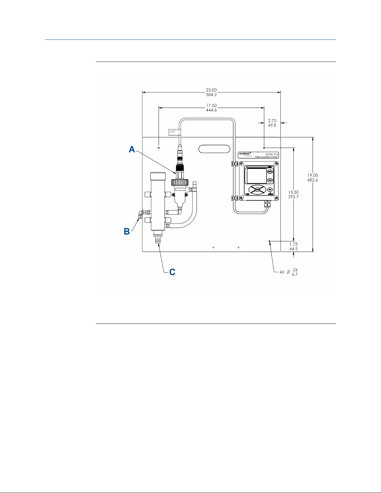
Figure 2-1: Rosemount FCL-01
A. Chlorine sensor
B. Inlet
C. Drain
Rosemount FCL 1056 13
Page 14
Install
May 2019 00809-0100-3412
Reference Manual
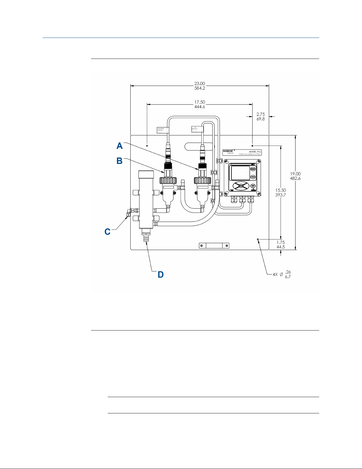
Figure 2-2: Rosemount FCL-02
A. pH sensor
B. Chlorine sensor
C. Inlet
D. Drain
A ¼-in. OD tubing compression fitting is provided for the sample inlet. If desired, you can
remove the compression fitting and replace it with a barbed fitting. The fitting screws into
a ¼-in. FNPT check valve. The check valve prevents the sensor flow cell from going dry if
sample flow is lost.
The sample drains through a ¾-in. barbed fitting.
1. Attach a piece of soft tubing to the fitting and allow the waste to drain to open
atmosphere.
Important
Do not restrict the drain line.
14 Emerson.com/Rosemount
Page 15

Reference Manual Install
00809-0100-3412 May 2019
2. Adjust the sample flow until the water level is even with the central overflow tube
and excess water is flowing down the tube.
3. Confirm that sample is flowing through the flow cells.
2.5 Install the sensor(s)
Emerson provides the Rosemount™ FCL with the sensor cable pre-wired to the transmitter.
Procedure
1. Connect the chlorine sensor (Rosemount 499ACL-01-54-VP) to the cable labeled
CL.
2. Connect the pH sensor (Rosemount 3900-VP-02-10) to the cable labeled pH.
The terminal end of the sensor is keyed to ensure proper mating with the cable
receptacle.
3. Once the key has slid into the mating slot, tighten the connection by turning the
knurled ring clockwise.
4. Screw the sensor(s) into the plastic fitting(s), which are held in the flow cell(s) by the
union nut.
Do not remove the protective cap on the sensor(s) until ready to put the sensor(s) in
service.
Rosemount FCL 1056 15
Page 16

Install Reference Manual
May 2019 00809-0100-3412
Figure 2-3: Rosemount FCL-01
A. Chlorine sensor
B. Inlet
C. Drain
16 Emerson.com/Rosemount
Page 17

Reference Manual Install
00809-0100-3412 May 2019
Figure 2-4: Rosemount FCL-02
A. pH sensor
B. Chlorine sensor
C. Inlet
D. Drain
Rosemount FCL 1056 17
Page 18

Install Reference Manual
May 2019 00809-0100-3412
18 Emerson.com/Rosemount
Page 19

Reference Manual Wire
00809-0100-3412 May 2019
3 Wire
3.1 Wire power
Wire AC mains power supply to the power supply board, which is mounted vertically on
the left hand side of the transmitter enclosure.
WARNING
Electrical shock
Electrical installation must be in accordance with the National Electrical Code (ANSI/
NFPA-70) and/or any other applicable national or local codes.
The power connector is at the top of the board.
Procedure
1. Unplug the connector from the board and wire the power cable to it.
Lead connections are marked on the connector. (L is live or hot; N is neutral; the
ground connection has the standard symbol.)
2. Run the power wiring through the conduit opening nearest the power terminal.
AC power wiring should be 14 gauge or greater.
3. Provide a switch or breaker to disconnect the transmitter from the main power
supply.
4. Install the switch or breaker near the transmitter and label it as the disconnecting
device for the transmitter.
3.2 Wire analog outputs
Two analog output currents are located on the main circuit board, which is attached to the
inside of the enclosure door.
Figure 3-1 shows the locations of the terminals. The connectors can be detached for
wiring. TB-1 is output 1. TB-2 is output 2. Polarity is marked on the circuit board.
Rosemount FCL 1056 19
Page 20

Wire
May 2019 00809-0100-3412
Figure 3-1: Analog output connections
Reference Manual
The analog outputs are on the main board near the hinged end of the enclosure door.
For best EMI/RFI protection, use shielded output signal cable enclosed in earth-grounded
metal conduit.
Keep output signal wiring separate from power wiring. Do not run signal and power or
relay wiring in the same conduit or close together in a cable tray.
3.3 Alarm wiring
The alarm relay terminal strip is located just below the power connector on the power
supply board.
See Figure 3-2.
20 Emerson.com/Rosemount
Page 21

Reference Manual Wire
00809-0100-3412 May 2019
Figure 3-2: Alarm relay connections
A. Alarm relay 1
B. Alarm relay 2
C. Alarm relay 3
D. Alarm relay 4
1. To remove the cover, grab it by the upper edges and pull straight out. The relay
terminal strip is at the top of the board.
2. Bring the relay wires through the rear conduit opening on the left hand side of the
enclosure and make connections to the terminals strip.
3. Replace the cover. The two tabs on the back edge of the cover fit into slots at the
rear of the enclosure, and the three small slots in the front of the cover snap into the
three tabs next to the relay terminal strip. See Figure 3-2. Once the tabs are lined
up, push the cover to snap it in place.
Keep alarm relay wiring separate from signal wiring. Do not run signal and power or relay
wiring in the same conduit or close together in a cable tray.
Rosemount FCL 1056 21
Page 22

Wire
May 2019 00809-0100-3412
Reference Manual
3.4 Wire sensor
The Rosemount™ FCL is provided with sensor cables pre-wired to the transmitter. If it is
necessary to replace the sensor cable, refer to the instructions below.
Procedure
1. Shut off power to the transmitter.
2. Loosen the four screws holding the front panel in place and let it drop down.
3. Locate the appropriate signal board.
Slot 1 (left) Slot 2 (center) Slot 3 (right)
communication input 1 (chlorine) input 2 (optional)
4. Loosen the gland fitting and carefully push the sensor cable up through the fitting
as you pull the board forward to gain access to the wires and terminal screws.
5. Wire the sensor to the signal board.
Refer to the wiring diagrams in Figure 3-3 and Figure 3-4.
Figure 3-3: Wiring Diagram for Free Chlorine Sensor
A. White
B. Resistance temperature device return
C. White/red
D. Resistance temperature device sense
E. Red
F. Resistance temperature device in
G. Clear
H. Resistance temperature device shield
I. +5 V out
J. -4.5 V out
K. Anode shield
L. Orange
M. Anode
N. Cathode shield
O. Gray
P. Cathode
22 Emerson.com/Rosemount
Page 23

Reference Manual
00809-0100-3412 May 2019
Connect green wire to metal conduit ground plate in bottom of enclosure.
Figure 3-4: Wiring Diagram for 3900VP-10 pH Sensor (Blue Cable)
A. White
B. White/red
C. Red
D. Blue
E. Clear (not used)
F. Clear
G. Orange
H. White/gray
I. Gray
J. Resistance temperature device return
K. Resistance temperature device sense
L. Resistance temperature device in
M. Ground solution
N. pH shield
O. In pH/ORP
P. Reference shield
Q. In reference
Wire
Green (connect to green grounding screw at bottom of enclosure).
6. Once the cable has been connected to the board, slide the board fully into the
enclosure while taking up the excess cable through the cable gland.
7. Tighten the gland nut to secure the cable and ensure a sealed enclosure.
3.5 Quick Start
Procedure
1. Once connections are secured and verified, apply power to the transmitter.
When the transmitter is powered up for the first time, Quick Start screens appear.
Using Quick Start is easy.
a. A backlit field shows the position of the cursor.
Rosemount FCL 1056 23
Page 24

Wire Reference Manual
May 2019 00809-0100-3412
b. To move the cursor left or right, use the keys to the left or right of the ENTER
key. To scroll up or down or to increase or decrease the value of a digit, use
the keys above and below the ENTER key. Use the left and right keys to move
the decimal point.
c. Press ENTER to store a setting. Press EXIT to leave without storing changes.
Pressing EXIT also returns the display to the initial Quick Start screen.
d. A vertical black bar with a downward pointing arrow on the right side of the
screen means there are more items to display. Continue scrolling down to
display all the items. When you reach the bottom of the list, the arrow points
up.
2. Choose the desired language. Scroll down to display more choices.
3. Choose Free Chlorine for sensor 1 (S1).
4. Choose the desired units for chlorine.
The screens in Step 5 and Step 6 only appear if you have a Rosemount™ FCL-02.
5. If you have a Rosemount FCL-01, go to Step 8. Otherwise, choose pH for Sensor 2
(S2).
24 Emerson.com/Rosemount
Page 25

Reference Manual
00809-0100-3412 May 2019
Wire
6. Choose Analyzer.
7. Choose Live/Continuous. Go to Step 9.
8. The screen below appears only if you have an FCL-01. Enter the pH of the process
liquid.
9. Choose the desired temperature units.
The main display appears. The outputs and alarms (if an alarm board is present) are
assigned to default values.
10. To change outputs, alarms, and other settings, go to the Main Menu and choose
Program. Follow the prompts.
Rosemount FCL 1056 25
Page 26

Wire Reference Manual
May 2019 00809-0100-3412
26 Emerson.com/Rosemount
Page 27

Reference Manual Wire
00809-0100-3412 May 2019
Rosemount FCL 1056 27
Page 28
Wire Reference Manual
May 2019 00809-0100-3412
28 Emerson.com/Rosemount
Page 29

Reference Manual Display and operation
00809-0100-3412 May 2019
4 Display and operation
4.1 Display
The transmitter has a four line display.
See Figure 4-1. You can customize the display to meet your requirements. Refer to
Configure the main display.
Figure 4-1: Main Display
When the transmitter is being programmed or calibrated, the display changes to a screen
similar to the one shown in Figure 4-2. The live readings appear in small font at the top of
the screen. The rest of the display shows programming and calibration information.
Programming items appear in lists. The screen can only show four items at a time, and the
arrow bar at the right of the screen indicates whether there are additional items in the list.
See Figure 4-3 for an explanation of the arrow bar.
Figure 4-2: Programming Screen Showing Item List
A. Live measurement\
B. Item list
C. Arrow bar
The position of the cursor is shown in reverse video. See Keypad and Program the
transmitter for more information.
Rosemount FCL 1056 29
Page 30

Display and operation Reference Manual
May 2019 00809-0100-3412
Figure 4-3: Arrow Bar
A. You are at the top of the list. There are more items for viewing. Scroll down.
B. You are at the bottom of the list. There are more items for viewing. Scroll up.
C. You are in the middle of the list. There are more items for viewing. Scroll up or down.
The arrow bar shows whether additional items in a list are available.
4.2 Keypad
Local communication with the transmitter is through the membrane keypad.
Figure 4-4 and Figure 4-5 explain the operation of the keys.
30 Emerson.com/Rosemount
Page 31

Reference Manual Display and operation
00809-0100-3412 May 2019
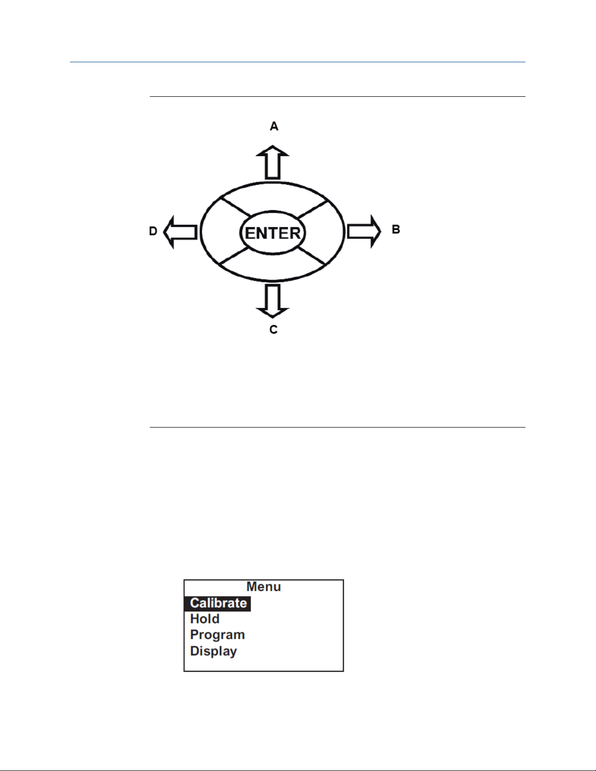
Figure 4-4: Transmitter Keypad
A. Press MENU. The Main Menu screen appears.
B. Press DIAG. The main diagnostic screen appears.
C. Navigation keys move the cursor in the direction indicated in Figure 4-5.
D. Press EXIT to leave a screen without storing changes. The display returns to the previous
screen.
E. Press ENTER to store a change or select an item. The display changes to the next screen.
Four navigation keys move the cursor around the screen. The position of the cursor is
shown in reverse video. The navigation keys are used to increase or decrease the value of a
numeral. Press ENTER to select an item and store numbers and settings. Press EXIT to
return to the previous screen without storing changes. Pressing MENU always causes the
main menu to appear.
Rosemount FCL 1056 31
Page 32
Display and operation Reference Manual
May 2019 00809-0100-3412
Figure 4-5: Navigation Keys
A. Moves cursor up or increases the value of the selected digit.
B. Moves cursor to the right.
C. Moves cursor down or decreases the value of the selected digit.
D. Moves cursor to the left.
The operation of the navigation keys is shown. To move a decimal point, highlight it and
then press Up or Down.
4.3 Program the transmitter
Setting up and calibrating the transmitter is easy. The following tutorial describes how to
move around in the programming menus. For practice, the tutorial also describes how to
assign ppm chlorine values to the 4 and 20 mA analog outputs.
Procedure
1. Press MENU.
The main Menu screen appears. There are four items in the main menu. Calibrate is
in reverse video, meaning that the cursor is on Calibrate.
32 Emerson.com/Rosemount
Page 33
Reference Manual Display and operation
00809-0100-3412 May 2019
2. To assign values to the analog outputs, you must open the Program sub-menu. Use
Down to move the cursor to Program. Press ENTER.
The Program menu appears. There are between five and seven items in the
Program menu. Diagnostic Setup appears only if you have the Rosemount™ FCL-02
with pH sensor. The screen displays four items at a time. The downward pointing
arrow on the right of the screen shows there are more items available in the menu.
3. To view the other items, use Down to scroll to the last item shown and continue
scrolling down. When you have reached the bottom, the arrow will point up. Move
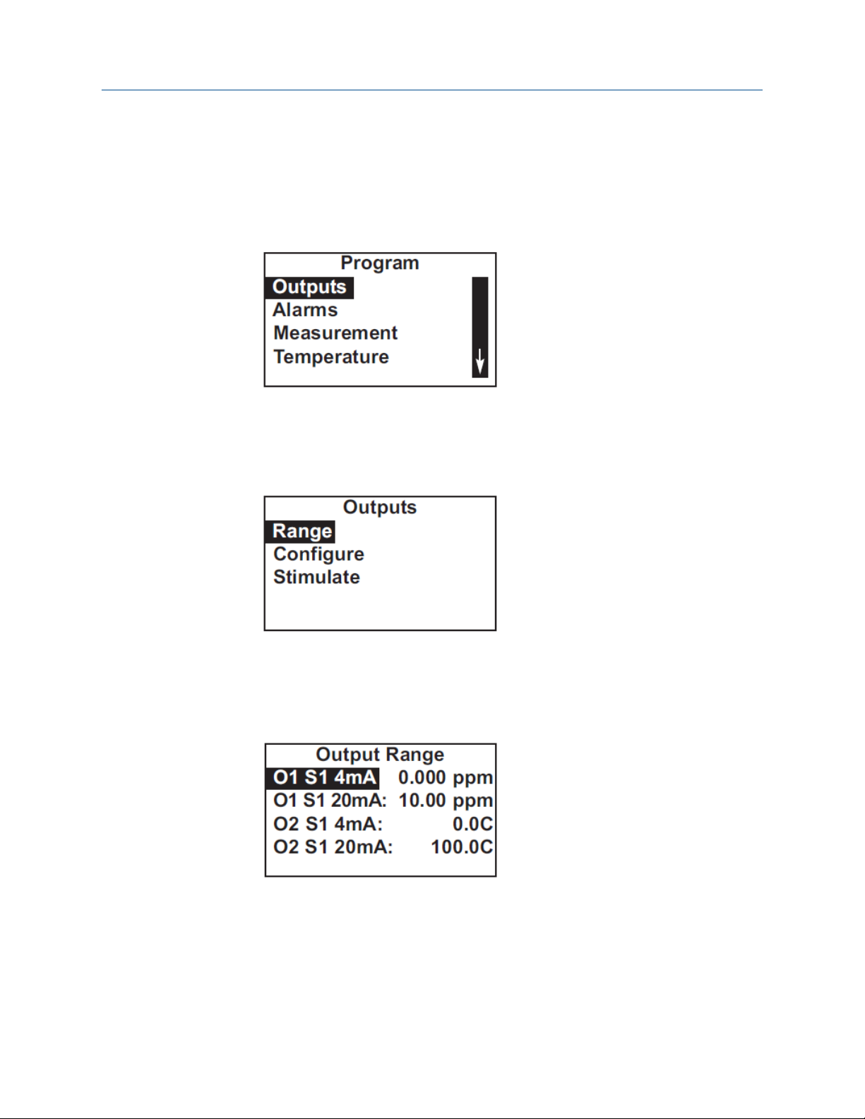
the cursor back to Outputs and press ENTER.
The Outputs screen appears. The cursor is on Range. Output range is used to assign
values to the low and high current outputs.
4. Press ENTER.
The Output Range screen appears. The screen shows the present values assigned
to output 1 (O1) and output 2 (O2). The screen also shows which sensors the
outputs are assigned to. S1 is sensor 1.. The assignments shown are the defaults for
the Rosemount FCL-01. Outputs are freely assignable under the Configure menu.
5. For practice, change the 20 mA settings for output 1 to 8.5 ppm.
a) Move the cursor to the O1 S1 20 mA: 10.00 line and press ENTER.
The screen below appears.
Rosemount FCL 1056 33
Page 34

Display and operation Reference Manual
May 2019 00809-0100-3412
b) Use the navigation keys to change 10.00 to 8.5 ppm. Use Left and Right to
move from digit to digit. Use Up and Down to increase or decrease the
numeral.
c) To move the decimal point, press Left or Right until the decimal point is
highlighted. Press Up to move the decimal point to the right. Press Down to
move to the left.
d) Press ENTER to store the setting.
The display returns to the summary screen shown below. Note that the 20 mA
setting for output 1 has changed to 8.50 ppm.
6. To return to the main menu, press MENU. To return to the main display, press
MENU and then EXIT.
4.4 Security
4.4.1 How the security code works
Security codes prevent accidental or unwanted changes to program settings or
calibrations. There are three levels of security.
1. A user can view the default display and diagnostic screens only.
2. A user has access to the calibration and hold menus only.
3. A user has access to all menus.
34 Emerson.com/Rosemount
Page 35

Reference Manual Display and operation
00809-0100-3412 May 2019
1. If a security code has been programmed, pressing MENU causes the security screen
to appear.
2. Enter the three-digit security code.
3. If the entry is correct, the main Menu screen appears. The user has access to the
sub-menus the code entitles him to.
4. If the entry is wrong, the Invalid code screen appears.
4.4.2
4.4.3
Assign security codes
See Configuring security settings.
Bypassing security codes
Call the factory.
4.5 Using hold
4.5.1 Putting sensor in hold
To prevent unwanted alarms and improper operation of control systems or dosing pumps,
place the alarms and outputs assigned to the sensor in hold before removing it for
maintenance.
Hold is also useful if calibration will cause an out of limits condition. During hold, outputs
assigned to the sensor remain at the last value, and alarms assigned to the sensor remain
in their present state.
Once in hold, the sensor remains in hold until hold is turned off. However, if power is loss
than restored, hold is automatically turned off.
4.5.2
Rosemount FCL 1056 35
Using the hold function
To put the transmitter in hold, complete the following steps.
Procedure
1. Press MENU.
The main Menu screen appears.
Page 36

Display and operation Reference Manual
May 2019 00809-0100-3412
2. Choose Hold.
The screen shows the current hold status for each sensor.
3. Select the sensor to be put in hold. Press ENTER.
4. To put the sensor in hold, choose Yes. To take the sensor out of hold, choose No.
4.6 Configure the main display
You can configure the main display to meet your requirements.
Procedure
1. Press MENU.
The main Menu screen appears.
2. Move the cursor to Display and press ENTER.
The screen shows the present configuration. There are four items: Main Format,
Language, Warning, and Contrast.
36 Emerson.com/Rosemount
Page 37

Reference Manual Display and operation
00809-0100-3412 May 2019
3. To make a change, move the cursor to the desired line and press ENTER.
A screen appears in which the present setting can be edited.
4. Press ENTER to store the setting.
5. Main Format lets you configure the second line in the main display as well as the
four smaller items at the bottom of the display. Move the cursor to the desired
place in the screen and press ENTER.
6. Scroll through the list of items and select the parameter you wish to be displayed.
7. Once you are done making changes, press EXIT twice to return to the Display menu.
8. Press MENU and then EXIT to return to the main display.
The following abbreviations are used in the quadrant display.
O
T temperature (live)
Tm temperature (manual)
M measurement
mV mV (pH)
I sensor current (Cl)
Slp slope
Gl glass impedance (pH)
RZ ref. impedance (pH)
output
If you have a dual input Rosemount™ 1056 Transmitter, other abbreviations might
appear. Consult the Rosemount 1056 Transmitter manual for more details.
9. Choose Language to change the language used in the display.
10. Choose Warning to disable or enable warning messages.
11. Choose Contrast to change the display contrast.
Rosemount FCL 1056 37
Page 38

Display and operation Reference Manual
May 2019 00809-0100-3412
12. To change the contrast, choose either lighter or darker and press ENTER.
Every time you press ENTER, the display becomes lighter or darker.
38 Emerson.com/Rosemount
Page 39

Reference Manual Programming the transmitter
00809-0100-3412 May 2019
5 Programming the transmitter
5.1 Programming overview
This section describes how to make the following program settings using the local keypad.
1. Configure and assign values to the analog current outputs.
2. Configure and assign values to the alarm relays.
3. Choose the type of chlorine measurement being made. This step is necessary
because the transmitter used with the Rosemount™ FCL can measure forms of
chlorine other than free chlorine.
4. Choose temperature units and automatic or manual temperature correction for
chlorine and pH (if a pH sensor is installed.
5. Set two levels of security codes.
6. Assign limits to diagnostic warnings (applies only if a pH sensor is installed).
7. Reset the transmitter to factory default settings.
5.2 Default settings
The transmitter leaves the factory with the default settings shown in Table 5-1. You can
change the settings to any value shown in the column labeled Choices.
Table 5-1: Default Settings
Item Choices Default
Sensor assignment
1. Sensor 1 Chlorine Chlorine
2. Sensor 2 pH pH
Outputs
1. Assignments (if Rosemount™ FCL-01)
a. Output 1 Chlorine, temp Chlorine
b. Output 2 Chlorine, temperature Temperature
2. Assignments (if Rosemount FCL-02)
a. Output 1 Chlorine, pH, temp Chlorine
b. Output 2 Chlorine, pH, temp pH
3. Range 0-20 or 4-20 mA 4-20 mA
4. 0 or 4 mA setting
a. Chlorine and pH -9999 to +9999 0
b. Temperature -999.9 to +999.9 0
Rosemount FCL 1056 39
Page 40

Programming the transmitter Reference Manual
May 2019 00809-0100-3412
Table 5-1: Default Settings (continued)
Item Choices Default
5. 20 mA setting
a. Chlorine -9999 to +9999 10
b. pH -9999 to +9999 14
c. Temperature -999.9 to +999.9 0
6. Fault current (fixed) 0.00 to 22.0 mA 22.0 mA
7. Dampening 0 to 999 sec 0 sec
8. Simulate 0.00 to 22.00 mA 12.00 mA
Alarms
1. Logic high or low AL1 low, AL2, 3, 4, high
2. Assignments
a. AL1 and AL2 ,Chlorine, pH, temperature, fault,
interval timer
b. AL3 and AL4 ,Chlorine, pH, temperature, fault,
interval timer
3. Deadband 0 to 9999 0
4. Interval timer settings
a. Interval time 0.0 to 999.9 hr 24.0 hr
b. On time 0 to 999 sec 10 sec
c. Recovery time 0 to 999 sec 60 sec
Measurement
a. Units ppm or mg/L ppm
b. Resolution 0.01 or 0.001 0.001
c. Input filter 0 to 999 sec 5 sec
2. pH (sensor 2)
a. Pre-amplifier location analyzer or sensor/junction box analyzer
b. solution temperature correction on or off off
c. resolution 0.01 or 0.1 0.01
d. input filter 0 to 999 sec 5 sec
ChlorineChlorine (sensor 1)
Temperature (sensor 1)
e. Reference impedance low or high low
Temperature related settings
1. Units °C or °F °C
2. Temperature compensation Automatic or manual Automatic
Security code
1. Calibrate/Hold 000 to 999 000
40 Emerson.com/Rosemount
Page 41
Reference Manual Programming the transmitter
00809-0100-3412 May 2019
Table 5-1: Default Settings (continued)
Item Choices Default
2. Program/Display 000 to 999 000
pH sensor diagnostic limits
1. Reference offset 0 to 9999 mV 60 mV
2. Diagnostics on or off on
3. Glass impedance temperature
correction
4. Glass fault (low impedance) 0 to 9999 MΩ 10 MΩ
5. Glass fault (high impedance) 0 to 9999 MΩ 1500 MΩ
6. Reference fault (high impedance) 0 to 9999 kΩ 40 kΩ
Calibration - pH
1. Stabilization criteria
a. Time interval 0 to 99 sec 10 sec
b. pH change 0.01 to 1.00 pH 0.02 pH
2. User-entered slope 0.00 to 99.99 mV/pH 59.16 mV/pH
3. User-entered offset -999 to +999 mV 0 mV
Calibration - analog outputs
1. 4 mA 0.000 to 22.000 mA 4.000 mA
2. 20 mA 0.000 to 22.000 mA 20.000 mA
on or off on
Rosemount FCL 1056 41
Page 42

Programming the transmitter Reference Manual
May 2019 00809-0100-3412
5.3 Configuring, ranging, and simulating outputs
5.3.1 Purpose of configuration
This section describes how to configure, range, and simulate the two analog current
outputs.
Important
Configure the outputs first.
1. Configuring an output means
a. Assigning a sensor and measurement (chlorine, pH, or temperature) to an
output.
b. Selecting a 4-20 mA or 0-20 mA output.
c. Choosing a linear or logarithmic output.
d. Adjusting the amount of dampening on the analog current output.
e. Selecting the value the output current goes to if the transmitter detects a
fault.
5.3.2
2. Ranging the outputs means assigning values to the low (0 or 4 mA) and high (20
mA) outputs.
3. Simulating an output means making the transmitter generate an output equal to
the value you enter.
Definitions
Analog current
output
Assigning an
output
Linear output
Logarithmic
output
Dampening
Fault
The transmitter provides either a continuous 4-20 mA or 0-20 mA
output signal proportional to chlorine, temperature, or pH.
Outputs can be assigned to any sensor and to either free chlorine or
temperature.
Linear output means the current is directly proportional to the value
of the variable assigned to the output (chlorine, pH, or temperature).
Logarithmic output means the current is directly proportional to the
common logarithm of the variable assigned to the output (chlorine,
pH, or temperature).
Output dampening smoothes out noisy readings. It also increases
response time. The time selected for output dampening is the time to
reach 63% of the final reading following a step change. Output
dampening does not affect the response time of the display.
The transmitter continuously monitors itself and the sensor(s) for
faults. If the transmitter detects a fault, a fault message appears in the
main display. At the same time, the output current goes to the value
programmed in this section. There are two output fault modes: fixed
and live. Fixed means the selected output goes to the previously
42 Emerson.com/Rosemount
Page 43
Reference Manual Programming the transmitter
00809-0100-3412 May 2019
programmed value (between 0.00 and 22.00 mA) when a fault
occurs. Live means the selected output is unaffected when the fault
occurs.
Ranging an
output
The outputs are fully rangeable, including negative numbers. If the
output is logarithmic, assigned values must be positive.
5.3.3 Configure outputs
Complete the following steps to configure the analog current outputs.
Procedure
1. Press MENU.
The main Menu screen appears.
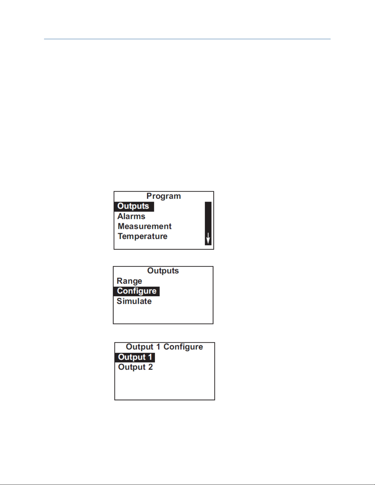
2. Move the cursor to Program and press ENTER.
The cursor is on Outputs.
3. Press ENTER.
4. Choose Configure.
5. Choose Output 1 or Output 2.
The screen shows the present configuration. There are six items: Assign (S1 is
sensor 1, S2 is sensor 2), Range, Scale, Dampening, Fault Mode, and Fault Value. To
Rosemount FCL 1056 43
Page 44

Programming the transmitter Reference Manual
May 2019 00809-0100-3412
display the fifth and sixth items, scroll to the bottom of the screen and continue
scrolling.
6. To make a change, move the cursor to the desired line and press ENTER.
A screen appears in which the present setting can be edited.
7. Press ENTER to store the setting.
For an explanation of terms, see Purpose of configuration and Definitions.
8. To return to the main display, press MENU and then EXIT.
5.3.4
Range outputs
Complete the following steps to range the outputs by assigning values to the low and high
outputs.
Procedure
1. Press MENU.
The main Menu screen appears.
2. Move the cursor to Program and press ENTER.
The cursor is on Outputs.
3. Press ENTER.
4. Choose Range.
44 Emerson.com/Rosemount
Page 45

Reference Manual Programming the transmitter
00809-0100-3412 May 2019
5. Choose Output 1 or Output 2.
The screen shows the present settings for the outputs. O1 is output 1, O2 is output
2, S1 is sensor 1, and S2 is sensor 2.
5.3.5
6. To make a change, move the cursor to the desired line and press ENTER.
A screen appears in which the present setting can be edited.
7. Press ENTER to store the setting.
For an explanation of terms, see Purpose of configuration and Definitions.
8. To return to the main display, press MENU and then EXIT.
Simulate outputs
Complete the following steps to simulate an output by making the transmitter generate
an output current equal to the value you enter.
Procedure
1. Press MENU.
The main Menu screen appears.
2. Move the cursor to Program and press ENTER.
The cursor is on Outputs.
3. Press ENTER.
Rosemount FCL 1056 45
Page 46
Programming the transmitter Reference Manual
May 2019 00809-0100-3412
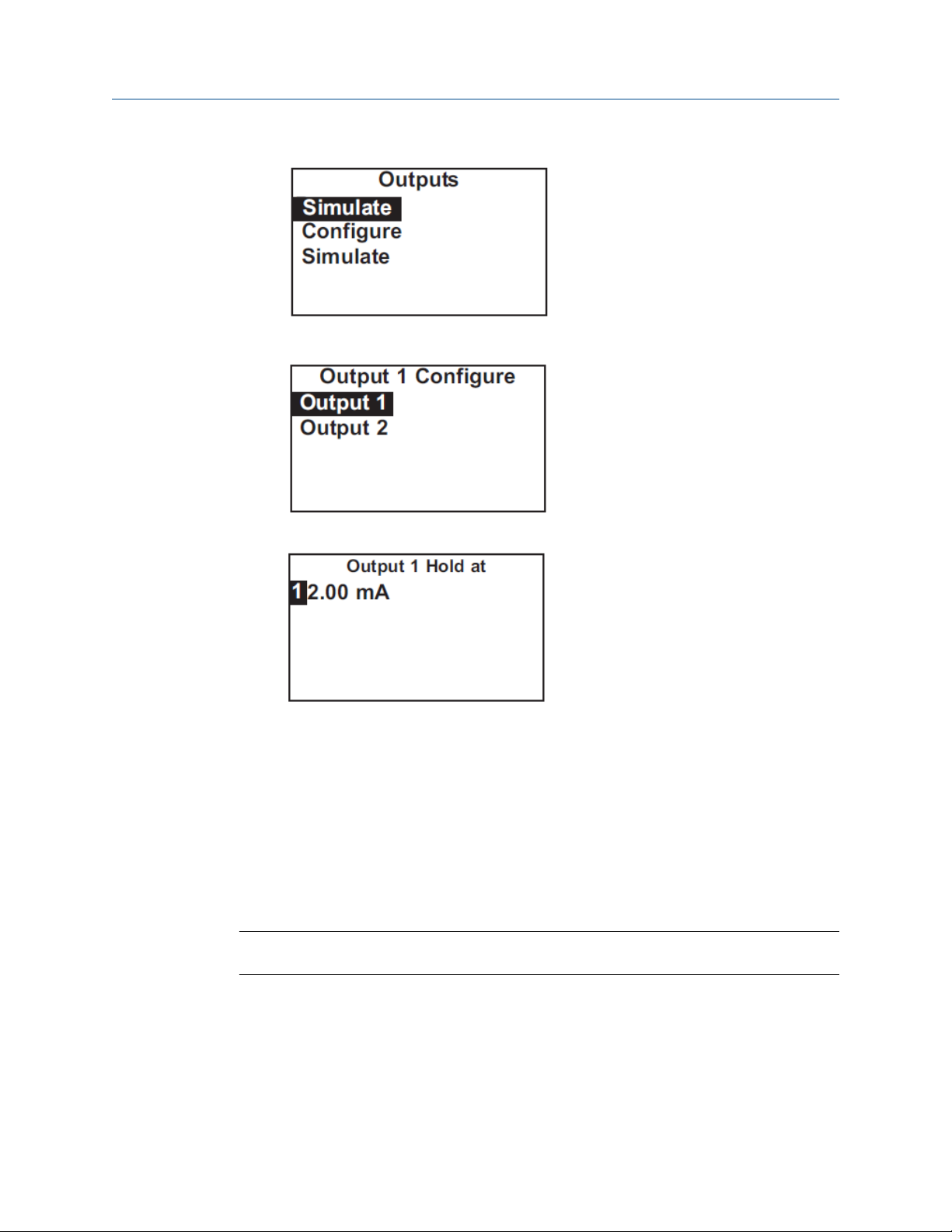
4. Choose Simulate.
5. Choose Output 1 or Output 2.
6. Enter the desired simulated output current.
7. To end the simulated current, press MENU or EXIT.
5.4 Configuring alarms and assigning setpoints
5.4.1 Purpose
This section describes how to configure and assign setpoints to the alarm relays, simulate
alarm action, and synchronize interval timers.
Important
Configure the alarms first.
1. Configuring an alarm means
a. Assigning a sensor and measurement (chlorine, pH, or temperature) to an
alarm. An alarm relay can also be used as a timer.
b. Selecting high or low logic.
c. Choosing the deadband.
46 Emerson.com/Rosemount
Page 47
Reference Manual Programming the transmitter
00809-0100-3412 May 2019
d. Setting the interval timer parameters.
2. Simulating an alarm means making the transmitter energize or de-energize an
alarm relay.
5.4.2 Definitions
Assigning
alarms
Fault alarm
Alarm logic,
setpoints,
and
deadbands
There are four alarm relays. The relays are freely assignable to any sensor
and to either the measurement (for example, chlorine) or temperature.
Alarm relays can also be assigned to operate as interval timers or as fault
alarms. A fault alarm activates when the transmitter detects a fault in
either itself of the sensor.
A fault condition exists when the transmitter detects a problem with the
sensor or with the transmitter itself that is likely to cause seriously
erroneous readings. If an alarm was programmed as a fault alarm, the
alarm activates. At the same time, a fault message appears in the main
display.
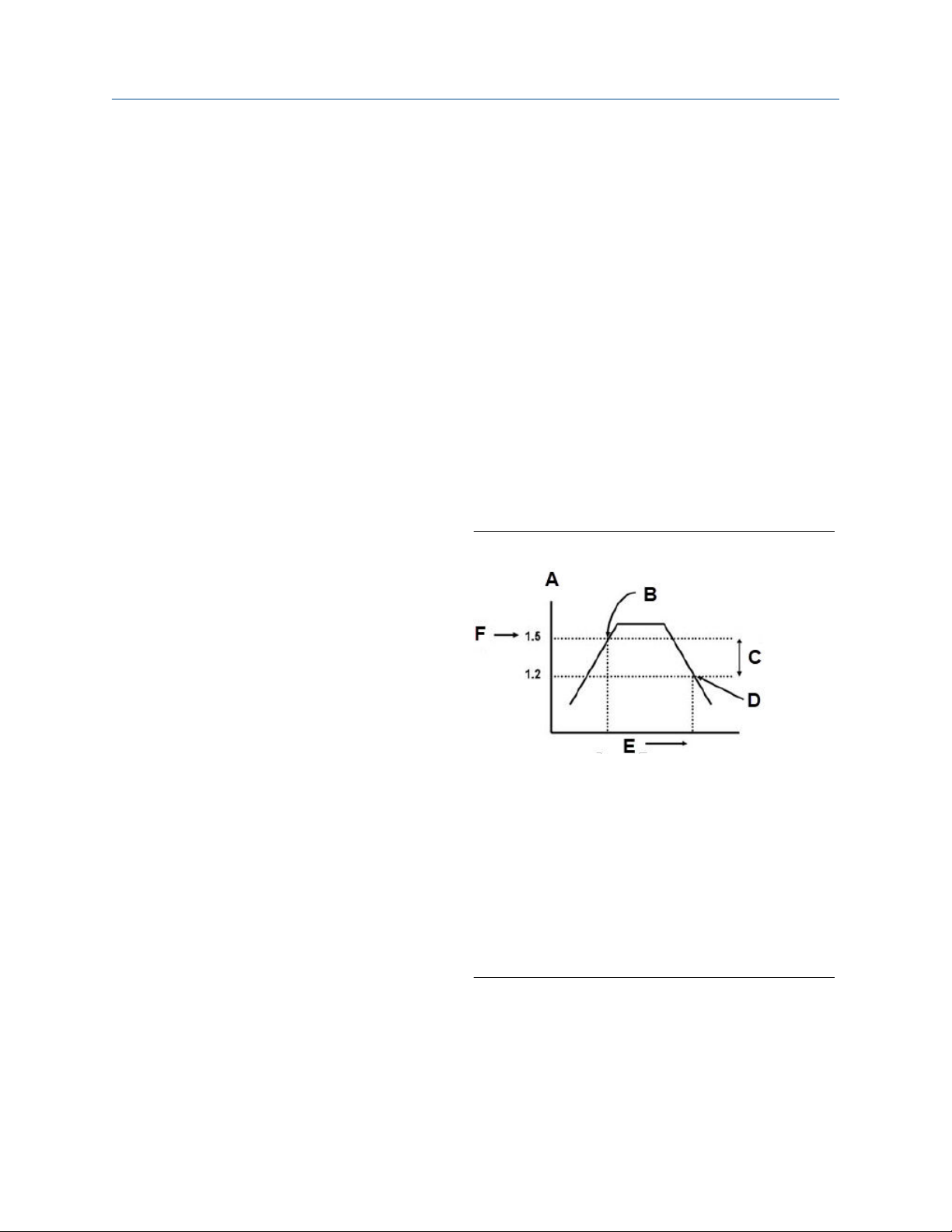
See Figure 5-1 and Figure 5-2.
Figure 5-1: High Alarm Logic
A. Chlorine, ppm
B. Alarm activates
C. Deadband = 0.3 ppm
D. Alarm deactivates
E. Time
F. High alarm setpoint
The alarm activates when the chlorine concentration
exceeds the high setpoint. The alarm remains
activated until the reading drops below the value
determined by the deadband.
Rosemount FCL 1056 47
Page 48

Programming the transmitter Reference Manual
May 2019 00809-0100-3412
Figure 5-2: Low Alarm Logic
A. Chlorine, ppm
B. Alarm deactivates
C. Deadband = 0.3 ppm
D. Time
E. Alarm activates
F. Low alarm setpoint
Interval timer
The alarm activates when the chlorine concentration
drops below the low setpoint. The alarm remains
activated until the reading increases above the value
determined by the deadband.
Any alarm relay can be used as an interval timer. Figure 5-3 shows how
the timer operates. While the interval timer is operating, the main
display, analog outputs, and assigned alarms for the sensor(s) can be put
on hold. During hold, the main display remains at the last value.
48 Emerson.com/Rosemount
Page 49

Reference Manual Programming the transmitter
00809-0100-3412 May 2019
Figure 5-3: Operation of the Interval Timer
A. On time duration (0 - 999 sec)
B. On (relay activated)
C. Timer interval (0 - 999.9 hr)
D. Recovery (0 - 999 sec)
E. Hold
The numbers in parentheses are the allowed values for
each timer parameter.
Synchronize
timer
If two or more relays are being used as interval timers, choosing
synchronize timers will cause each timer to start one minute later than
the preceding timer.
5.4.3 Configure alarms and assign setpoints
The Rosemount™ FCL has an optional alarm relay board. This section describes how to
configure and assign setpoints to the alarm relays, simulate alarm action, and synchronize
interval timers.
Important
Configure the alarms first.
1. Configuring an alarm means
a. Assigning a sensor and measurement to an alarm. An alarm relay can also be
used as a timer.
b. Selecting high or low logic.
c. Choosing the deadband.
d. Setting the interval timer parameters.
2. Simulating an alarm means making the transmitter energize or de-energize an
alarm relay.
Procedure
1. Press MENU.
Rosemount FCL 1056 49
Page 50

Programming the transmitter Reference Manual
May 2019 00809-0100-3412
The main Menu screen appears.
2. Move the cursor to Program and press ENTER.
3. Choose Alarms.
4. Choose Configure/Setpoint.
5. Choose Alarm 1, Alarm 2, Alarm 3, or Alarm 4.
The screens summarizes the present configuration and setpoints. There are eight
items:
• Setpoint
• Assign (S1 is sensor 1 and S2 is sensor 2)
• Logic
• Deadband
• Interval time
50 Emerson.com/Rosemount
Page 51

Reference Manual Programming the transmitter
00809-0100-3412 May 2019
• On time
• Recover time
• Hold while active
The last four items describe the operation of the timer. Only four items are shown at
a time. To view the remaining items, scroll to the bottom of the screen and
continue scrolling.
6. To make a change, move the cursor to the desired line and press ENTER.
A screen appears in which the present setting can be edited.
7. Press ENTER to store the setting.
For an explanation of terms, see Purpose and Definitions.
8. To return to the main display, press MENU and then EXIT.
5.4.4
Simulate alarms
Complete the following steps to make the transmitter energize or de-energize an alarm
relay.
Procedure
1. Press MENU.
The main Menu screen appears.
2. Move the cursor to Program and press ENTER.
3. Choose Alarms.
4. Choose Simulate.
Rosemount FCL 1056 51
Page 52

Programming the transmitter Reference Manual
May 2019 00809-0100-3412
5. Choose Alarm 1, Alarm 2, Alarm 3, or Alarm 4.
5.4.5
6. Choose Don't simulate, De-energize, or Energize.
7. Press MENU or EXIT to end simulation.
Synchronize timers
Synch Timers is available only if two or more alarm relays have been configured as interval
timers.
Procedure
1. Press MENU.
The main Menu screen appears.
2. Move the cursor to Program and press ENTER.
3. Choose Alarms.
52 Emerson.com/Rosemount
Page 53

Reference Manual Programming the transmitter
00809-0100-3412 May 2019
The summary display shows the current Synch Timers setting (Yes or No).
4. To make a change, choose Synch Timers and press ENTER.
A screen appears in which the present setting can be edited.
5. Press ENTER to store the setting.
For an explanation of terms, see Purpose and Definitions.
6. To return to the main display, press MENU and then EXIT.
5.5 Configuring the measurement
5.5.1 Purpose of configuring measurement
This section explains how to do the following:
1. Program the transmitter to measure free chlorine (and pH). This step is necessary,
because the transmitter can be used with other sensors to measure other chlorine
oxidants.
2. Set automatic or manual pH correction for the free chlorine measurement.
3. Set the level of electronic filtering of the raw signals from the chlorine and pH
sensors.
4. Make various pH measurement settings. The transmitter supplied with the
Rosemount FCL is designed to be as versatile as possible. The pH settings below are
needed in some applications but are not used when pH is measured for the purpose
of correcting free chlorine readings.
a. Solution temperature correction
b. Transmitter isopotential point
c. Reference impedance
5.5.2
Definitions - chlorine
Chlorine
oxidants
Although the Rosemount™ FCL is used to measure free chlorine only, the
transmitter used in the Rosemount FCL can be used to measure other
chlorine oxidants, for example, monochloramine and total chlorine.
Filter
Rosemount FCL 1056 53
The transmitter applies a software filter to the raw sensor current. The filter
reduces noise but increases the response time. The available filter(s)
depend on the time setting. If the filter is between 0 and 10 seconds, the
Page 54

Programming the transmitter Reference Manual
May 2019 00809-0100-3412
transmitter applies a window filter. The window filter averages the
measured value within the filter time. For example, if the filter is 5 seconds
and a step increase is applied to the input, the displayed value increases
linearly, reaching the final value after 5 seconds. If the filter is set to greater
than 10 seconds, the transmitter applies either an adaptive filter or a
continuous filter. An adaptive filter discriminates between noise and real
process change. It filters changes below a fixed threshold value but does
not filter changes that exceed the threshold. It is best used in situations
where the noise is relatively low. A continuous filter dampens all changes.
The filter timer setting is approximately equal to the time constant, the
amount of time required for the reading to reach 63% of the final value
following a step change.
pH
correction
Resolution
Free chlorine is the sum of hypochlorous acid (HOCl) and hypochlorite ion
(OCl¯). The relative amount of each depends on pH. As pH increases, the
concentration of HOCl decreases, and the concentration of OCl¯ increases.
Because the sensor responds only to HOCl, a pH correction is necessary to
properly convert the sensor current into a free chlorine reading. The
Rosemount FCL uses either continuous (live) or manual pH correction. In
continuous (live) correction, the transmitter continuously monitors the pH
of the sample and corrects the free chlorine readings for changes in pH. In
manual pH correction, the transmitter uses the pH you enter for the pH
correction. Generally, if the pH changes more than about 0.2 units over
short periods of time, Emerson recommends continuous (live) pH
correction. If the pH is relatively steady or subject to only seasonal
changes, manual pH correction is adequate.
If the chlorine concentration is less than 1.00 ppm (mg/L), the display
resolution can be set to 0.XX or 0.XXX.
5.5.3 Definitions - pH/ORP
ORP
Redox
ORP is oxidation-reduction potential. It is the voltage difference
between a noble metal indicator electrode (like platinum) and a silver/
silver chloride reference electrode.
Redox is redox potential. It has the opposite sign from the ORP.
Preamplifier
Solution
temperature
correction
Resolution
54 Emerson.com/Rosemount
The pH signal has a high impedance. Before it can be used, it must be
converted into a low impedance signal. The pre-amplifier accomplishes
this task, and it can be located in either the transmitter or the sensor.In
the Rosemount™ FCL-02, the preamplifier is located in the transmitter.
The pH of a solution, particularly an alkaline one, is a function of
temperature. If the temperature changes, so will the pH, even though
the concentration of the acid or base remains constant. Solution
temperature compensation converts the pH at the measurement
temperature to the pH at a reference temperature (77 ° F [25 °C]).
Generally, solution temperature compensation is used only in the
determination of pH in condensate, feedwater, and boiler water in
steam electric power plants.
The pH display resolution is user selectable: XX.X or XX.XX.
Page 55
Reference Manual Programming the transmitter
00809-0100-3412 May 2019
Filter
Reference
impedance
The transmitter applies a software filter to the raw voltage value
coming from the pH sensor. The filter reduces noise, but increases the
response time. See Definitions - chlorine for more information.
Usually, the impedance of the reference electrode in a pH sensor is
low. However, a few pH sensors have high reference impedance, and
the transmitter must be told that the reference impedance is high. The
pH sensor used in the Rosemount FCL-02 has low reference
impedance.
5.5.4 Configure measurement
Complete the following steps to configure the transmitter to measure free chlorine.
Procedure
1. Press MENU.
The main Menu screen appears.
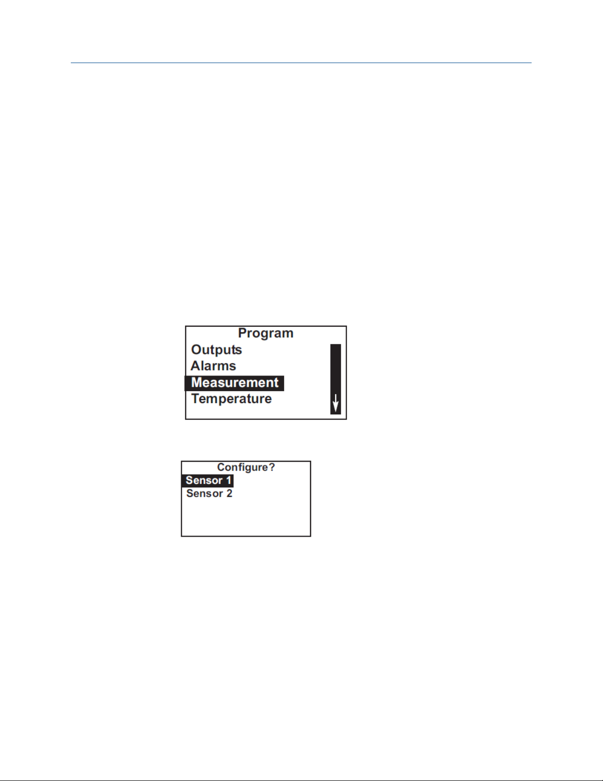
2. Move the cursor to Program and press ENTER.
3. Choose Measurement.
The screen below appears only if you have a Rosemount™ FCL-02.
Choose Sensor 1 (chlorine) or Sensor 2 (pH).
The screen summarizes the present configuration for sensor 1 (chlorine). If you
have a Rosemount FCL-02, the items are Measure, Units, Filter, Free Cl Correct, and
Resolution. If you have a Rosemount FCL-01, the items are Measure, Units, Filter,
Manual pH, and Resolution. Only four items are shown at a time.To view the
remaining items, scroll to the bottom of the screen and continue scrolling.
4. To make a change, move the cursor to the desired line and press ENTER.
A screen appears in which the present setting can be edited.
5. To store the setting, press ENTER.
a) .For Measurement, choose Free Chlorine. Do not choose pH Independ. Free
Cl.
b) Leave Filter at the default value (5 sec) unless readings are noisy.
Rosemount FCL 1056 55
Page 56

Programming the transmitter Reference Manual
May 2019 00809-0100-3412
c) If you have a Rosemount FCL-02, choose either Live/Continuous or Manual
for Free Cl Correct (free chlorine correction). Live/Continuous means the
transmitter will use the pH measured on the second channel to continuously
correct the chlorine reading for changes in the sample pH. Manual means the
transmitter will use a fixed pH value entered by you to convert the raw
chlorine signal to a ppm reading.
d) If you have a Rosemount FCL-01, Free Cl Correct (free chlorine correction)
will not appear. Instead, enter the desired pH correction value for Manual pH.
The screen summarizes the present configuration for sensor 2 (pH). There are six
items: Measure, Preamp, Sol'n Temp Corr, Resolution, Filter, and Reference Z
(reference impedance). Only four items are shown at a time. To view the remaining
items, scroll to the bottom of the screen and continue scrolling.
6. To make a change move the cursor to the desired line and press ENTER.
A screen appears in which the present setting can be edited.
7. To store the settings, press ENTER.
a) For pH Preamp, choose Analyzer.
b) For pH Reference Z, choose Low.
c) Leave Filter at the default value unless readings are noisy.
For an explanation of terms, see Definitions - chlorine and Definitions - pH/ORP.
8. To return to the main display, press MENU and then EXIT.
5.6 Configuring temperature related settings
5.6.1 Purpose
This section describes how to do the following:
1. Choose temperature units.
2. Choose automatic or manual temperature correction for membrane permeability.
3. Choose automatic or manual temperature compensation for pH.
4. Enter a temperature for manual temperature compensation.
5.6.2
Definitions - chlorine
Automatic
temperature
correction
The free chlorine sensor is a membrane-covered amperometric sensor.
It produces a current directly proportional to the rate of diffusion of free
chlorine through the membrane. The diffusion rate, in turn, depends on
the concentration of free chlorine in the sample and membrane
permeability. Membrane permeability is a function of temperature. As
temperature increases, permeability increases. Thus, an increase in
temperature will cause the sensor current and the transmitter reading
to increase even though the concentration of chlorine remained
constant. In automatic temperature correction, the transmitter uses
56 Emerson.com/Rosemount
Page 57

Reference Manual Programming the transmitter
00809-0100-3412 May 2019
the temperature measured by the sensor to continuously correct for
changes in membrane permeability.
Manual
temperature
correction
In manual temperature correction, the transmitter uses the
temperature you enter for correction. It does not use the actual process
temperature. Do not use manual temperature correction unless the
measurement and calibration temperatures differ by no more than
about 2 °C. Manual temperature correction is useful if the sensor
temperature element has failed and a replacement sensor is not
available.
5.6.3 Definitions - pH
Automatic
temperature
compensation
Manual
temperature
compensation
A pH sensor produces a voltage that depends on the pH of the
sample. The transmitter uses a temperature-dependent factor to
convert the voltage to pH. In automatic temperature compensation,
the transmitter uses the temperature measured by the pH sensor to
calculate the conversion factor. For maximum accuracy, use
automatic temperature compensation.
In manual temperature compensation, the transmitter converts
measured voltage to pH using the temperature you enter. It does not
use the actual process temperature. Do not use manual temperature
compensation unless the process temperature varies no more than
about ±2 °C. Manual temperature correction is useful if the sensor
temperature element has failed and a replacement is not available.
5.6.4 Configure temperature related settings
Complete the following steps to set the temperature units and to select automatic or
manual temperature correction.
This section describes how to do the following:
1. Choose temperature units.
2. Choose automatic or manual temperature correction for membrane permeability.
3. Choose automatic or manual temperature compensation for pH.
4. Enter a temperature for manual temperature compensation.
Procedure
1. Press MENU.
The main Menu screen appears.
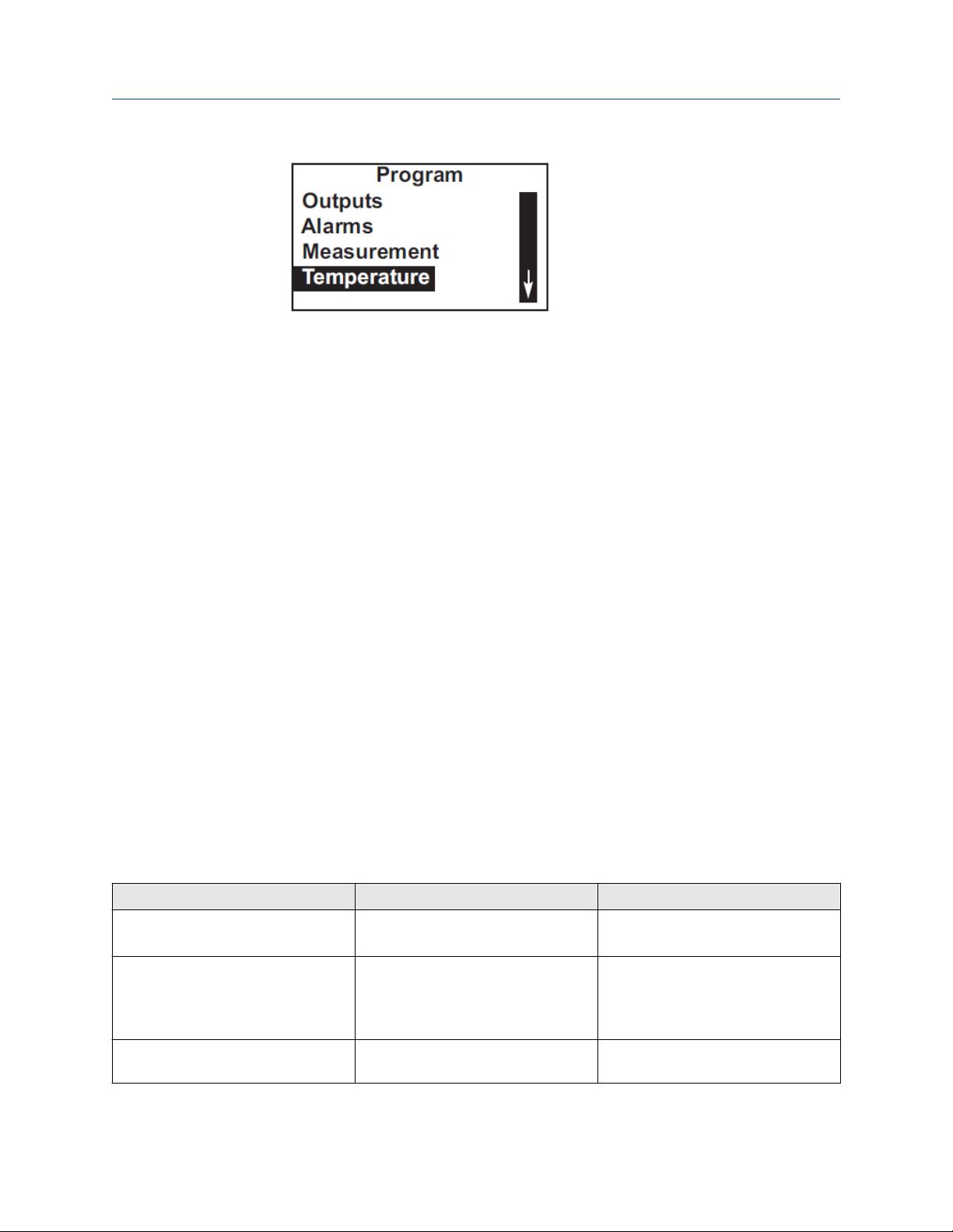
2. Move the cursor to Program and press ENTER.
Rosemount FCL 1056 57
Page 58
Programming the transmitter Reference Manual
May 2019 00809-0100-3412
3. Choose Temperature.
The screen summarizes the present sensor configuration.
There are between three and five items. Units, S1 Temp Comp, and S2 Temp Comp
always appear. If manual temperature compensation was selected, the manual
temperature values entered for each sensor (S1 and S2 Manual) also appear.
4. To make a change, move the cursor to the desired line and press ENTER.
A screen appears in which the present setting can be edited.
5. To store a setting, press ENTER.
For an explanation of terms, see Purpose, Definitions - chlorine, and Definitions -
pH.
6. To return to the main display, press MENU and then EXIT.
5.7 Configuring security settings
5.7.1 Purpose
This section describes how to set security codes. There are three levels of security.
1. A user can view the default display and diagnostic screens only.
2. A user has access to the calibration and hold menus only.
3. A user has access to all menus.
The security code is a three digit number. The table shows what happens when different
security codes (XXX and YYY) are assigned to Calibration/Hold and All. 000 means no
security.
Calibration/Hold
000 XXX User enters XXX and has access to all
XXX YYY User enters XXX and has access to
All What happens
menus.
Calibration and Hold menus only. User
enters YYY and has access to all
menus.
XXX 000 User needs no security code to have
access to all menus.
58 Emerson.com/Rosemount
Page 59

Reference Manual Programming the transmitter
00809-0100-3412 May 2019
Calibration/Hold All What happens
000 000 User needs no security code to have
access to all menus.
5.7.2 Configure security settings
This section describes how to set security codes. There are three levels of security.
1. A user can view the default display and diagnostic screens only.
2. A user has access to the Calibration and Hold menus only.
3. A user has access to all menus.
The security code is a three digit number. The table shows what happens when different
security codes (XXX and YYY) are assigned to Calibration/Hold and All. 000 means no
security.
Procedure
1. Press MENU.
The main Menu screen appears.
2. Move the cursor to Program and press ENTER.
3. Scroll to the bottom of the screen and continue scrolling until Security is
highlighted. Press ENTER.
The screen shows the existing security codes.
4. To make a change, move the cursor to the desired line and press ENTER.
A screen appears in which the present setting can be edited.
5. Press ENTER to store a change.
The security code takes effect two minutes after pressing ENTER.
6. To return to the main display, press MENU and then EXIT.
Rosemount FCL 1056 59
Page 60

Programming the transmitter Reference Manual
May 2019 00809-0100-3412
5.8 Set up diagnostics
5.8.1 Purpose of diagnostic setup
Note
Diagnostic setup applies only to pH sensors. It appears only if you are using the
Rosemount™ FCL-02..
This section describes how to do the following:
1. Turn pH sensor diagnostics on and off.
2. Set pH sensor diagnostic limits.
5.8.2
Definitions
Diagnostics
Reference
offset
Glass and
reference
impedance
Glass
impedance
temperature
correction
pH sensor diagnostics are useful in troubleshooting calibration
problems and in predicting when a pH sensor should be replaced.
Diagnostics can also alert you that the sensor is no longer submerged
in the process liquid.
pH sensors are designed to have a potential of 0 mV in pH 7 buffer.
The reference offset is the actual potential (in mV) in pH 7 buffer. A
new sensor typically has a reference offset of a few mV. Old sensors
can have offsets of 60 mV or more.
During operation, the transmitter continuously measures the
impedance of the pH glass membrane. If the pH sensor has a solution
ground, the transmitter also continuously measures the impedance of
the reference junction. The Rosemount™ 3900VP pH sensor supplied
with the FCL-02 has a solution ground. The Rosemount 399VP sensor,
supplied with earlier versions of the FCL-02, did not have a solution
ground. If you are using a Rosemount 399VP sensor, reference
impedance diagnostics will not be available. Glass and reference
impedance measurements provide useful information about sensor
health and cleanliness.
The impedance of a glass electrode is a strong function of
temperature. As temperature decreases, the impedance increases. For
glass impedance to be a useful indicator of sensor condition, the
impedance must be corrected to a reference temperature.
Glass fault high
60 Emerson.com/Rosemount
A typical glass electrode has an impedance of about 100 MΩ. As the
sensor ages, glass impedance increases. Extremely high impedance
(greater than about 1000 MΩ) implies the sensor is nearing the end of
its life. High impedance may also mean that the sensor is not
submerged in the process liquid.
Page 61

Reference Manual Programming the transmitter
00809-0100-3412 May 2019
5.8.3 Set up diagnostics
Complete the following steps to set up diagnostics on your FCL-02 pH sensor.
Procedure
1. Press MENU.
The main Menu screen appears.
2. Move the cursor to Program and press ENTER.
3. Scroll to the bottom of the screen and continue scrolling until Diagnostic Setup is
highlighted. Press ENTER.
Diagnostics are available only for pH sensors. In the FCL-02, the pH sensor is Sensor
2.
The screen summarizes the present diagnostic settings and limits. There are nine
items. To show items beyond the first four in the list, scroll to the bottom of the list
and continue scrolling.
4. To make a change, move the cursor to the desired line and press ENTER.
A screen appears in which the present settings can be edited. Emerson
recommends that you set the settings to the values in the table.
Setting Default
Ref Offset 60 mV
Diagnostic On
Z Temp Correct'n On
GI Fault High 1000 MΩ
Ref Fault High 20 KΩ
5. To return to the main display, press MENU and then EXIT.
5.9 Resetting the transmitter
5.9.1 Purpose
This section describes how to clear user-entered values and restore default settings. There
are three resets:
1. Resetting to factory default clears ALL user-entered settings, including sensor and
analog output calibration, and returns ALL settings and calibration values to the
factory defaults.
2. Resetting a sensor calibration to the default value clears user-entered calibration
data for the selected sensor but leaves all other user-entered data unaffected.
3. Resetting the analog output calibration clears only the user-entered analog output
calibration. It leaves all other user-entered settings unchanged.
Rosemount FCL 1056 61
Page 62
Programming the transmitter Reference Manual
May 2019 00809-0100-3412
5.9.2 Reset the transmitter
Complete the following steps to reset the transmitter.
Procedure
1. Press MENU.
The main Menu screen appears.
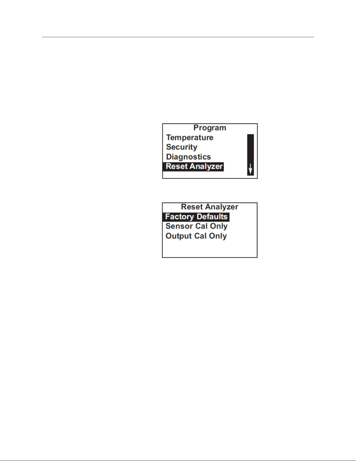
2. Move the cursor to Program and press ENTER.
3. Scroll to the bottom of the screen and continue scrolling until Reset Analyzer is
highlighted. Press ENTER.
4. Choose whether to reset all user-entered values (Factory Defaults), sensor
calibration (Sensor Cal Only), or output calibration (Output Cal Only).
If you choose Sensor Cal Only or Output Cal Only, a second screen appears in which
you can select which sensor or output calibration to reset.
5. To return to the main display, press MENU and then EXIT.
62 Emerson.com/Rosemount
Page 63

Reference Manual
00809-0100-3412 May 2019
Calibrate
6 Calibrate
6.1 Introduction
The Calibrate menu allows you to do the following:
1. Calibrate the temperature sensing element in the chlorine and pH sensors.
2. Calibrate the pH sensor. Four methods are available:
a. Two-point calibration with automatic buffer recognition.
b. Manual two-point calibration.
c. Standardization.
d. Manual entry of pH sensor slope and offset.
3. Calibrate the chlorine sensor.
4. Calibrate the analog outputs.
6.2 Calibrate temperature
Temperature is important in the measurement of chlorine and pH for different reasons.
The free chlorine sensor is a membrane-covered amperometric sensor. As the sensor
operates, free chlorine diffuses through the membrane and is consumed at an electrode
immediately behind the membrane. The reaction produces a current that depends on the
rate at which the free chlorine diffuses through the membrane. The diffusion rate, in turn,
depends on the concentration of free chlorine and how easily it passes through the
membrane (the membrane permeability). Because membrane permeability is a function
of temperature, the sensor current changes if the temperature changes. To account for
changes in sensor current caused by temperature alone, the transmitter automatically
applies a membrane permeability correction. The membrane permeability changes about
3% per °C at 77 °F (25 °C), so a 1 °C error in temperature produces about a 3% error in the
reading.
Temperature is also important in pH measurements.
1. The transmitter uses a temperature dependent factor to convert measured cell
voltage to pH. Normally a slight inaccuracy in the temperature reading is
unimportant unless the pH reading is significantly different from 7.00. Even then,
the error is small. For example, at pH 12 and 25 °C (77 °F), a 1 °C error produces a pH
error less than ±0.02.
2. During autocalibration, the transmitter recognizes the buffer being used and
calculates the actual pH of the buffer at the measured temperature. Because the pH
of most buffers changes only slightly with temperature, reasonable errors in
temperature do not produce large errors in the buffer pH. For example, a 1 °C error
causes at most an error of ±0.03 in the calculated buffer pH.
Without calibration, the accuracy of the temperature measurement is about ±0.4 °C.
Calibrate the sensor/transmitter unit if:
Rosemount FCL 1056 63
Page 64
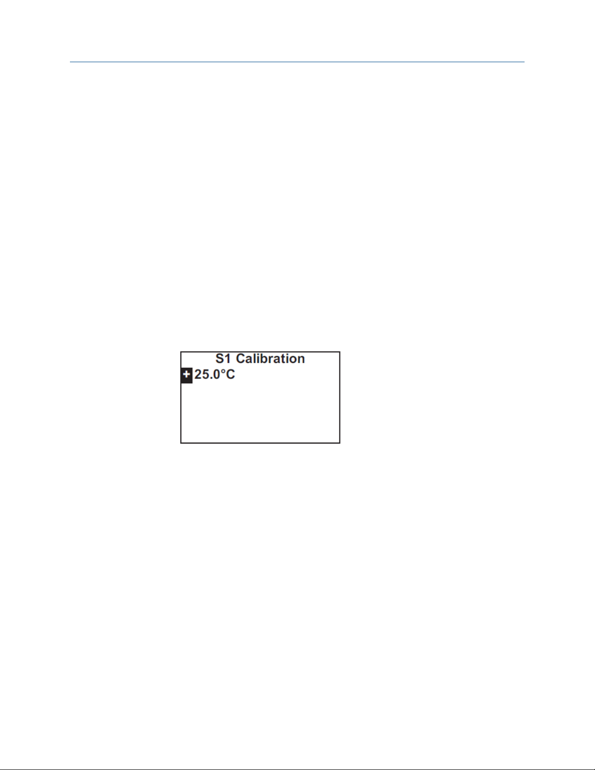
Calibrate
May 2019 00809-0100-3412
1. ±0.4 °C accuracy is not acceptable.
2. The temperature measurement is suspected of being in error. Calibrate
temperature by making the transmitter reading match the temperature measured
with a standard thermometer.
Procedure
1. Remove the sensor from the flow cell. Place it in an insulated container of water
along with a calibrated thermometer. Submerge at least the bottom two inches of
the sensor.
2. Allow the sensor to reach thermal equilibrium.
The time constant for the sensor is about five minutes, so it may take as long as
thirty minutes for equilibration.
3. Press MENU.
The main Menu screen appears. The cursor is on Calibrate.
4. Press ENTER.
5. Choose the sensor you wish to calibrate.
Sensor 1 is the chlorine sensor. Sensor 2 (if present) is the pH sensor.
Reference Manual
6. Choose Temperature.
7. Change the display to match the temperature read from the calibrated
thermometer. Press ENTER.
If the present temperature is more than 5 °C different from the value entered, an
error message appears.
8. To force the transmitter to accept the calibration, choose Yes. To repeat the
calibration, choose No.
For troubleshooting assistance, see Troubleshooting when no error message is
showing.
9. To return to the main display, press MENU and then EXIT.
6.3 Calibration - free chlorine
6.3.1 Purpose
As Figure 6-1 shows, a free chlorine sensor generates a current directly proportional to the
concentration of free chlorine in the sample. Calibrating the sensor requires exposing it to
a solution containing no free chlorine (zero standard) and to a solution containing a known
amount of free chlorine (full-scale standard).
64 Emerson.com/Rosemount
Page 65

Reference Manual Calibrate
00809-0100-3412 May 2019
Figure 6-1: Sensor Current as a Function of Free Chlorine Concentration
The zero standard is necessary, because chlorine sensors, even when no chlorine is in the
sample, generate a small current called the residual current or zero current. The
transmitter compensates for the residual current by subtracting it from the measured
current before converting the result to a chlorine value. New sensors require zeroing
before being placed in service, and sensors should be zeroed whenever the electrolyte
solution is replaced. Either of the following makes a good zero standard:
• Deionized water containing about 500 ppm sodium chloride. Dissolve about 0.5 grams
(1/8 teaspoonful) of table salt in 1 liter of water.
Important
Do not use deionized water alone for zeroing the sensor. The conductivity of the zero
water must be greater than 50 µS/cm.
• Tap water known to contain no chlorine. Expose tap water to bright sunlight for at least
24 hours.
The purpose of the full-scale standard is to establish the slope of the calibration curve.
Because stable chlorine standards do not exist, the sensor must be calibrated against a
test run on a grab sample of the process liquid. Several manufacturers offer portable test
kits for this purpose. Observe the following standards when taking and testing the grab
sample.
• Take the grab sample from a point as close to the FCL as possible. Be sure that taking
the sample does not alter the flow of the sample to the unit. It is best to install the
sample tap just downstream from the tap for the FCL.
• Chlorine solutions are unstable. Run the test immediately after taking the sample. Try
to calibrate the sensor when the chlorine concentration is at the upper end of the
normal operating range.
Free chlorine measuremetns also require a pH correction. Free chlorine is the sum of
hypochlorous acid (HOCl) and hypochlorite ion (OCl¯). The relative amount of each
depends on pH. As pH increases, the HOCl decreases and concentration of OCl¯. Because
the sensor responds only to HOCl, a pH correction isnecessary to properly convert the
sensor current into a free chlorine reading.
The sensor uses either continuous (live) or manual pH correction. In continuous (live)
correction, the transmitter continuously monitors the pH of the sample and corrects the
free chlorine reading for changes in pH. In manual pH correction, the transmitter uses the
pH you enter for the pH correction. Generally, if the pH changes more than about 0.2 units
over short periods of time, continuous (live) pH correction is recommended. If the pH is
relatively steady or subject only to seasonal changes, manual pH correction is adequate.
During calibration, the transmitter must know the pH of the solution. If the transmitter is
using automatic pH correction, the pH sensor (properly calibrated) must be in the process
liquid before starting the calibration. If the transmitter is using manual pH correction, be
sure to enter the pH value before starting the calibration.
Rosemount FCL 1056 65
Page 66

Calibrate
May 2019 00809-0100-3412
Reference Manual
6.3.2 Zero the sensor
Procedure
1. Place the sensor in the zero standard.
Be sure no air bubbles are trapped against the membrane.
The sensor current drops rapidly at first and then gradually reaches a stable zero
value.
2. To monitor the sensor current, press DIAG.
3. Choose Sensor 1.
The input current is the first line in the display. Note the units: nA is nanoamps: µA is
microamps. Typical zero current for the new sensor is between -10 and 10 nA. A
new sensor or a sensor in which the electrolyte solution has been replaced may
require several hours (occasionally as long as overnight) to reach a minimum zero
current.
Important
Do not start the zero routine until the sensor has been in the zero solution for at
least two hours.
4. Press MENU.
The main Menu screen appears. The cursor is on Calibrate.
5. Press ENTER.
6. Choose the sensor you wish to calibrate.
Sensor 1 is the chlorine sensor. Sensor 2 (if present) is the pH sensor.
7. Choose Free Chlorine.
8. Choose Zero Cal.
The transmitter automatically starts the zero calibration.
If the zero calibration was successful, the following screen appears.
66 Emerson.com/Rosemount
Page 67

Reference Manual
00809-0100-3412 May 2019
If the zero current is moderately larger than expected, an error message appears.
Calibrate
6.3.3
9. To force the transmitter to accept the zero current, choose Yes. To repeat the
calibration, choose No.
If the zero current is much larger than expected, the Sensor zero failed screen
appears.
The transmitter will not update the zero current.
10. To return to the main display, press MENU and then EXIT.
Calibrate the sensor
Procedure
1. Place the chlorine sensor in the chlorine flow cell.
2. If continuous (live) pH correction is being used, calibrate the pH sensor (Section)
and place it in the pH flow cell. If manual pH correction is being used, measure the
pH of the sample and enter the value.
See Configuring the measurement.
3. Adjust the chlorine concentration until it is near the upper end of the operating
range. Wait until the transmitter reading is stable before starting calibration.
4. Press MENU.
The main Menu screen appears. The cursor is on Calibrate.
Rosemount FCL 1056 67
Page 68

Calibrate Reference Manual
May 2019 00809-0100-3412
5. Press ENTER.
6. Choose the sensor you wish to calibrate.
Sensor 1 is the chlorine sensor. Sensor 2 (if present) is the pH sensor.
7. Choose Free ChlorinepH Independ. Free Cl.
8. Choose In Process Cal.
9. Follow the screen prompts. Once the reading is stable, press ENTER. Take the
sample and press ENTER.
At this point, the transmitter stores the present sensor current and temperature
and uses those values in calibration.
10. Determine the free chlorine concentration in the sample and enter the value in the
screen below.
See Purpose for sampling and testing precautions.
If the calibration was successful, the live reading changes to the value entered in
step 9, and the display returns to the screen in step 6. If the sensitivity is too far
outside the range of expected values the following screen appears.
68 Emerson.com/Rosemount
Page 69

Reference Manual Calibrate
00809-0100-3412 May 2019
The transmitter doesn't update the calibration. For troubleshooting assistance, see
Troubleshooting when no error message is showing.
11. To return to the main display, press MENU and then EXIT.
6.4 Calibration - pH
6.4.1 Purpose
A pH sensor consists of a glass and reference electrode. Usually, the two electrodes are
combined into a single body, called a combination pH sensor.
6.4.2
When the sensor is placed in an aqueous solution, it produces a voltage proportional to
pH. An ideal pH sensor has a potential of 0 mV in pH 7 solution and a slope of -59.16
mV/pH at 25 °C (77 °F), that is, a unit increase in pH causes the potential to drop 59.16 mV.
However, even in a new pH sensor, the slope and offset are rarely equal to the ideal values.
And, as the sensor ages, the offset typically increases, and the slope decreases. For these
reasons, a new pH sensor should be calibrated before use, and the sensor should be
recalibrated at regular intervals. A pH sensor is calibrated by exposing it to standard
solutions having known pH values. The standard solutions are called buffers.
Definitions
Automatic buffer
calibration
In automatic buffer calibration, the transmitter recognizes the buffer
and uses the temperature-corrected pH value in the calibration. The
table lists the buffers the transmitter recognizes. Temperature-pH
data are valid between at least 0 and 60 °C (32 and 140 °F).
Buffer list Buffer pH
Standard
DIN19267 1.09, 3.06, 4.65, 6.79, 9.23, 12.75
Ingold 1.993, 4.005, 7.002, 9.206
Merck 2.002, 4.014, 7.003, 9.004, 12.009
(1)
1.68, 3.56 3.78, 4.01, 4.64, 6.86,
7.01, 7.41, 9.18, 10.01, 12.45
Fisher 1.00, 2.00, 3.00, 4.00, 5.00, 6.00,
7.00, 8.00, 9.00, 10.00, 11.00
(1) With the exception of pH 7.01 buffer, the standard buffers are NIST
buffers.
Rosemount FCL 1056 69
Page 70
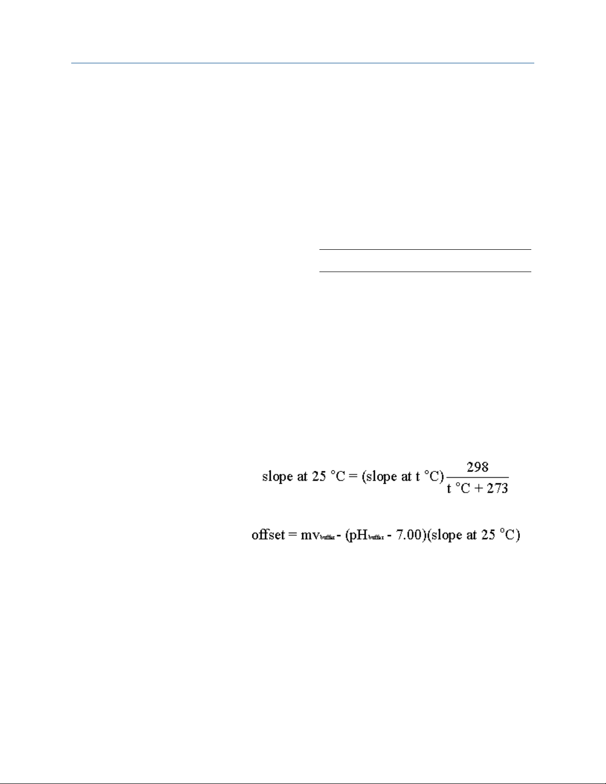
Calibrate
May 2019 00809-0100-3412
The transmitter also measures noise and drift and does not accept
calibration data until readings are stable. Stability criteria are userprogrammable.
The use of automatic buffer calibration minimizes errors, and
Emerson strongly recommends its use.
Reference Manual
Manual buffer
calibration
Slope and offset
Standardization
User entered
slope and offset
In manual calibration, you must enter the pH value of the buffer at
the temperature of the buffer. In addition, you must judge when pH
readings are stable.
Once the transmitter successfully completes the calibration, it
calculates and displays the calibration slope and offset. The slope is
reported at 25 °C (77 °F). Figure 6-2 defines the terms.
Figure 6-2: Calibration Slope and Offset
The pH measured by the transmitter can be changed to match the
reading from a second or referee instrument. The process of making
the two readings agree is called standardization. During
standardization, the difference between the two pH values is
converted to the equivalent voltage. The voltage, called the
reference offset, is added to all subsequent measured sensor
voltages before they are converted to pH. If a pH sensor is buffered,
then standardized and placed back in the buffer solution, the
measured pH will differ from the buffer pH by an amount equivalent
to the standardization offset.
If the slope and offset are known from other measurements, they
can be directly entered into the transmitter. Enter the slope as a
positive number corrected to 25 °C. To calculate the slope at 25 °C
from the slope at temperature t °C, use the equation:
To calculate the offset, use the following equation. The offset can be
either positive or negative.
Stability setting
During automatic calibration, the transmitter measures noise and
drift and does not accept calibration data until readings are stable.
Calibration data will be accepted as soon as the pH reading is
constant to within the factory-set limits of less than 0.02 pH change
in 10 seconds. The stability settings are programmable.
6.4.3 Autocalibrate pH sensor
Procedure
1. Obtain two buffer solutions.
Ideally, the buffer pH values should bracket the range of pH to be measured.
70 Emerson.com/Rosemount
Page 71

Reference Manual
00809-0100-3412 May 2019
Calibrate
2. Remove the sensor from the flow cell. If the process and buffer temperatures are
appreciably different, place the sensor in a container of tap water at the buffer
temperature.
Do not start the calibration until the sensor has reached the buffer temperature.
3. Press MENU.
The main Menu screen appears. The cursor is on Calibrate.
4. Press ENTER.
5. Choose the sensor you wish to calibrate.
Sensor 1 is the chlorine sensor. Sensor 2 is the pH sensor.
6. Choose pH.
7. Choose Buffer Cal.
8. Choose Auto.
9. Choose Start Auto Cal.
If you wish to change the stability criteria or the pH buffer list from the default
values, choose Setup instead and go to step 15. The default stability is defined as a
less than 0.02 change in 10 seconds. The default buffer list is Standard. See the
table in Definitions.
10. Rinse the sensor with water and place it in the first buffer. Be sure the glass bulb and
reference junction are completely submerged. Swirl the sensor.
11. Press ENTER.
Once the pH reading meets the stability requirements, the screen changes to show
the nominal pH of the buffer. The nominal pH is the pH value at 25 °C (77 °F).
12. If the displayed value is not correct, press Up or Down until the correct value is
showing.
13. Press ENTER.
Once the pH reading meets the stability requirements, the screen changes to show
the nominal pH of the buffer.
14. If the displayed value is not correct, press Up or Down until the correct value is
showing.
15. Press ENTER.
If the calibration is successful, the screen below is displayed for five seconds. The
display then returns to the screen in step 7. If the calibration is not successful, the
existing calibration data is not changed. A screen appears identifying the error (high
slope, low slope, or offset error). For troubleshooting, see Troubleshooting when no
error message is showing - pH. If you chose setup in Step 9, the screen below
appears.
16. To make a change, move the cursor to the desired line and press ENTER.
A screen appears in which the present setting can be edited.
17. Press ENTER to store the change.
18. To return to the main display, press MENU and then EXIT.
Rosemount FCL 1056 71
Page 72

Calibrate Reference Manual
May 2019 00809-0100-3412
6.4.4 Procedure - manual calibration
Complete the following steps to manually calibrate the pH sensor.
Procedure
1. Obtain two buffer solutions.
Ideally, the buffer pH values should bracket the range of pH to be measured.
2. Remove the sensor from the flow cell. If the process and buffer temperatures are
appreciably different, place the sensor in a container of tap water at the buffer
temperature.
Do not start the calibration until the sensor has reached the buffer temperature.
3. Press MENU.
The main Menu screen appears. The cursor is on Calibrate.
4. Press ENTER.
5. Choose the sensor you wish to calibrate.
Sensor 1 is the chlorine sensor. Sensor 2 is the pH sensor.
6. Choose pH.
7. Choose Buffer Cal.
8. Choose Manual.
9. Choose Buffer 1.
10. Rinse the sensor with water and place it in the first buffer. Be sure the glass bulb and
reference junction are completely submerged. Swirl the sensor.
11. Watch the pH reading for sensor 2 (S2) at the top of the screen. Once the reading is
stable, enter the pH value of the buffer at the buffer temperature and press ENTER.
The display returns to the screen shown in step 9.
12. Choose Buffer 2.
13. Remove the sensor from the first buffer.
14. Rinse with water and place it in the second buffer. Be sure the glass bulb and
reference junction are completely submerged. Swirl the sensor.
15. Press ENTER.
16. Watch the pH reading for sensor 2 (S2) at the top of the screen. Once the reading is
stable, enter the pH value of the buffer at the buffer temperature and press ENTER.
If the calibration is successful, the screen below is displayed for five seconds. The
display then returns to the screen in step 7. If the calibration is not successful, the
existing calibration data is not changed. A screen appears identifying the error (high
slope, low slope, or offset error). For troubleshooting, see Section.
17. To return to the main display, press MENU and then EXIT.
72 Emerson.com/Rosemount
Page 73

Reference Manual
00809-0100-3412 May 2019
Calibrate
6.4.5 Standardize pH value
You can change the pH value measured by the transmitter to match the reading from a
second or referee instrument. The process of making the two readings agree is called
standardization.
Procedure
1. Place the sensor in the flow cell. Wait until pH readings are stable.
2. Press MENU.
The main Menu screen appears. The cursor is on Calibrate.
3. Press ENTER.
4. Choose the sensor you wish to calibrate.
Sensor 1 is the chlorine sensor. Sensor 2 is the pH sensor.
5. Choose pH.
6. Choose Standardize.
7. Once the reading is stable, measure the pH of the liquid using a referee instrument.
Because the pH of may natural and treated waters depends on temperature,
measure the pH of the sample immediately after taking it. For poorly buffered
samples, determine the pH of a continuously flowing sample from a point as close
as possible to the sensor. Change the reading to match the reading of the referee
instrument.
If the calibration is successful, the screen below is displayed for five seconds. The
display then returns to the screen in step 3. If the calibration is not successful, the
existing calibration data is not changed. A screen appears identifying the error (high
slope, low slope, or offset error). For troubleshooting, see Troubleshooting when no
error message is showing.
8. To return to the main display, press MENU and then EXIT.
6.5 Calibration - analog outputs
6.5.1 Trimming analog outputs
Although Emerson calibrates the analog outputs at the factory, you can trim them in the
field to match the reading from a standard milliameter. You can trim both the low (0 or 4
mA) and high (20 mA) outputs
6.5.2
Rosemount FCL 1056 73
Calibrate analog outputs
Procedure
1. Connect a calibrated milliameter across the output you wish to calibrate. If a load is
already connected to the output, disconnect the load.
Do not put the milliameter in parallel with the load.
2. Press MENU.
The main Menu screen appears. The cursor is on Calibrate.
Page 74

Calibrate Reference Manual
May 2019 00809-0100-3412
3. Press ENTER.
4. Choose the output you wish to calibrate.
The transmitter simulates the low output current.
5. Change the value in the display to match the reading from the milliameter.
The transmitter simulates the 20 mA output current.
6. Change the value in the display to match the reading from the milliameter.
If the calibration was successful, the screen below appears.
If the user entered value is more than ±1 mA different from the nominal value, a
possible error screen appears.
7. To force the transmitter to accept the calibration, choose Yes.
8. To return to the main display, press MENU and then EXIT.
74 Emerson.com/Rosemount
Page 75

Reference Manual Digital communications
00809-0100-3412 May 2019
7 Digital communications
The transmitter supplied with the Rosemount FCL does not have the digital
communications option.
Rosemount FCL 1056 75
Page 76

Digital communications Reference Manual
May 2019 00809-0100-3412
76 Emerson.com/Rosemount
Page 77

Reference Manual Maintenance
00809-0100-3412 May 2019
8 Maintenance
8.1 Replace sensor circuit board
The Rosemount™ 1056 transmitter used with the Rosemount FCL requires little routine
maintenance.
Clean the transmitter case and front panel by wiping with a clean soft cloth dampened
with water only. Do not use solvents, like alcohol, that might cause a buildup of static
charge.
Sensor circuit boards are replaceable.
PN Description
21207-00 pH/ORP/ISE sensor board
24203-01 Chlorine sensor board
WARNING
Electrical shock
Disconnect main power and relay contacts to separate power source before servicing.
To replace the board:
Procedure
1. Turn off power to the transmitter.
2. Loosen the four screws holding the front panel in place and let the front panel drop
down.
3. Loosen the gland fitting and carefully push the sensor cable up through the fitting
as you pull out the circuit board.
4. Once you have access to the terminal strip, disconnect the sensor.
5. Unplug the sensor board from the main board.
See Figure 3-2.
6. Slide the replacement board partially into the board slot. Plug the sensor board into
the main board and reattach the sensor wires.
7. Carefully pull the sensor cable through the gland fitting as you push the sensor
board back into the enclosure.
8. Close the front panel.
9. Turn on power.
Rosemount FCL 1056 77
Page 78

Maintenance Reference Manual
May 2019 00809-0100-3412
8.2 Chlorine sensor
8.2.1 General
When used in clean water, the sensor requires little maintenance. Generally, the sensor
needs maintenance when the response becomes sluggish or noisy or when readings drift
following calibration.
Maintenance frequency is best determined by experience. For a sensor used in potable
water, expect to clean the membrane every month and replace the membrane and
electrolyte solution every three months.In water containing large amounts of suspended
solids, for example, open recirculating cooling water, membrane cleaning or replacement
will be more frequent.
8.2.2
8.2.3
Cleaning the membrane
Clean the membrane with water sprayed from a wash bottle.
Important
Do not use tissues to clean the membrane.
Replacing the electrolyte solution and membrane
WARNING
HARMFUL SUBSTANCE
Fill solution may cause irritation. May be harmful if swallowed. Read and follow manual.
Procedure
1. Unscrew the membrane retainer.
2. Remove the membrane assembly and O-ring.
See Figure 8-1.
78 Emerson.com/Rosemount
Page 79

Reference Manual
00809-0100-3412 May 2019
Maintenance
Figure 8-1: Chlorine Sensor Parts
A. Membrane retainer
B. Membrane assembly
C. O-ring
D. Cathode
E. Electrolyte fill plug (wrap with pipe tape)
F. Pressure equalizing port
G. Information label
3. Hold the sensor over a container with the cathode pointing down.
4. Remove the fill plug.
5. Allow the electrolyte solution to drain out.
6. Inspect the cathode.
a) If it is tarnished, clean it using a cotton-tipped swab dipped in baking soda or
alumina.
Use type A dry powder alumina intended for metallographic polishing of
medium and soft metals.
b) Rinse thoroughly with water.
7. Wrap the plug with two turns of pipe tape and set aside..
8. Prepare a new membrane.
a) Hold the membrane assembly with the cup formed by the membrane and
membrane holder pointing up.
b) Fill the cup with electrolyte solution.
9. Hold the sensor at about a 45° angle with the cathode end pointing up.
10. Add electrolyte solution through the fill hole until the liquid overflows.
11. Tap the sensor near the threads to release trapped air bubbles.
12. Add more electrolyte solution if necessary.
Rosemount FCL 1056 79
Page 80
Maintenance Reference Manual
May 2019 00809-0100-3412
13. Place the fill plug in the electrolyte port and begin screwing it in.
14. After several threads have engaged, rotate the sensor so that the cathode is
pointing up and continue tightening the fill plug.
Do not overtighten.
15. Place a new O-ring in the groove around the cathode post.
16. Cover the holes at the base of the cathode stem with several drops of electrolyte
solution.
17. Insert a small blunt probe, like a toothpick with the end cut off, through the
pressure equalizing port.
See .
CAUTION
EQUIPMENT DAMAGE
Do not use a sharp probe. It will puncture the bladder and destroy the sensor.
18. Gently press the probe against the bladder several times to force liquid through the
holes at the base of the cathode stem. Keep pressing the bladder until no air
bubbles can be seen leaving the holes. Be sure the holes remain covered with
electrolyte solution.
19. Place a drop of electrolyte solution on the cathode; then place the membrane
assembly over the cathode.
20. Screw the membrane retainer in place.
The sensor may require several hours operating at the polarizing voltage to
equilibrate after the electrolyte solution has been replenished.
Table 8-1: Spare Parts
Part number Description
33523-00 Electrolyte fill plug
9550094 O-ring, Viton 2-014
33521-00 Membrane retainer
23501-08 Free chlorine membrane assembly: includes one membrane assembly
and one O-ring
23502-08 Free chlorine membrane kit: includes three membrane assemblies and
three O-rings
9109536 #4 free chlorine sensor fill solution, 4 oz (120 mL)
80 Emerson.com/Rosemount
Page 81

Reference Manual Maintenance
00809-0100-3412 May 2019
8.3 pH sensor
8.3.1 pH sensor maintenance
When used in clean water, the pH sensor requires little maintenance.
Generally, the sensor needs maintenance when the response becomes sluggish or noisy.
In clean water, the typical cleaning frequency is once a month. In water containing large
amounts of suspended solids, for example, open recirculating cooling water, cleaning
frequency will be substantially greater.
8.3.2 Cleaning the sensor
Complete the following steps to clean the pH sensor.
Procedure
1. Remove soft deposits by rinsing with a stream of water from a wash bottle.
2. If the sensor becomes coated with rust, dissolve the rust by soaking the sensor in
dilute citric acid (dissolve 5 grams of citric acid crystals in 100 mL of water) for no
longer than thirty minutes at room temperature.
3. Rinse the sensor thoroughly with water and soak in pH buffer for several hours.
4. Recalibrate the sensor in buffers before returning it to service.
8.3.3
Other maintenance
The 3900VP-02-10 sensor supplied with the Rosemount FCL-02 is disposable. It has no
replaceable parts.
8.4 Constant head flow controller
8.4.1 General head flow controller information
After a period of time, deposits may accumulate in the constant head overflow chamber
and in the tubing leading to the flow cell(s). Deposits increase the resistance to flow and
cause the flow to gradually decrease. Loss of flow may ultimately have an impact on the
sensor performance.
The flow controller is designed to provide about 2 gal/hr (120 mL/min) flow. Loss of flow to
about 1 gal/hr (60 mL/min) causes about a 5% decrease in chlorine sensor output.
Loss of flow has almost no effect on pH sensor performance other than to increase the
overall response time.
Rosemount FCL 1056 81
Page 82
Maintenance Reference Manual
May 2019 00809-0100-3412
8.4.2 Cleaning the flow controller
The flow controller can be taken apart completely for cleaning.
Procedure
1. Use a strong flow of water to flush out the tubing.
Use a pipe cleaner or small bottlebrush to remove more adherent deposits.
2. To prevent leaks, apply a thin layer of silicone grease (or equivalent) to the two Orings as the base of the overflow chamber and to the O-ring sealing the central
overflow tube to the base.
8.4.3 Other maintenance
Table 8-2 and Figure 8-2 show the replacement parts for the flow controller assembly used
in the Rosemount FCL-01. Table 8-3 and Figure 8-3 show replacement parts for the flow
controller assembly used in the Rosemount FCL-02.
Table 8-2: Rosemount FCL-01 Constant Head Flow Controller Assembly Replacement Parts
Location in
Figure 8-2
1 24039-00 Flow cell for chlorine sensor with bubble shedding nozzle
2 24040-00 O-ring kit, two 2-222 and one 2-024 silicone O-rings with lubricant
3 33812-00 Dust cap for constant head flow controller
4 9322032 Elbow, 1/4 in. FNPT x 1/4 in. OD tubing
5 9350029 Check valve, 1/4 in. FNPT
6 33823-00 Outside tube for constant head device
PN Description
82 Emerson.com/Rosemount
Page 83

Reference Manual Maintenance
00809-0100-3412 May 2019
Figure 8-2: Rosemount FCL-01 Constant Head Flow Controller Assembly Replacement
Parts
Table 8-3: Rosemount FCL-02 Constant Head Flow Controller Assembly Replacement Parts
Location in
Figure 8-3
1 24039-00 Flow cell for chlorine sensor with bubble shedding nozzle
2 24039-01 Flow cell for pH sensor
3 24040-00 O-ring kit, two 2-222 and one 2-024 silicone O-rings with lubricant
4 33812-00 Dust cap for constant head flow controller
5 9322032 Elbow, 1/4 in. FNPT x 1/4 in. OD tubing
6 9350029 Check valve, 1/4 in. FNPT
7 33823-00 Outside tube for constant head device
Rosemount FCL 1056 83
PN Description
Page 84

Maintenance Reference Manual
May 2019 00809-0100-3412
Figure 8-3: Rosemount FCL-02 Constant Head Flow Controller Assembly Replacement
Parts
84 Emerson.com/Rosemount
Page 85
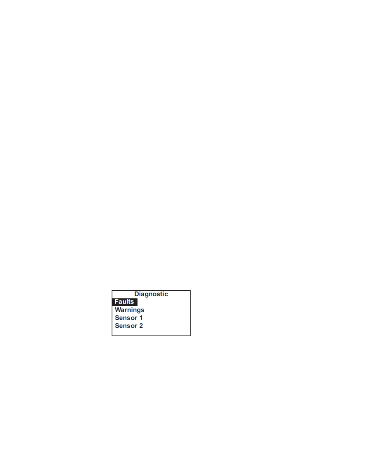
Reference Manual Troubleshoot
00809-0100-3412 May 2019
9 Troubleshoot
9.1 Overview
When the transmitter identifies a problem, the word warning or fault appears
intermittently in the lower line the display. When the fault or warning message
appears, press DIAG for more information.
See Use the diagnostic feature.
Warning
Fault
The transmitter also displays warning messages if a calibration is seriously in error. For
more information, see Use the diagnostic feature.
The instrument or sensor is usable, but you should take steps as soon as
possible to correct the condition causing the warning.
The measurement is seriously in error and is not to be trusted. A fault
condition might also mean that the transmitter has failed. Correct fault
conditions immediately. When a fault occurs, the analog output goes to 22.00
mA or to the value programmed in Configure outputs.
9.2 Use the diagnostic feature
Complete the following steps to troubleshoot your transmitter with the diagnostic
feature.
Procedure
1. To read diagnostic messages, press DIAG.
The screen below appears.
2. To display fault messages, select Faults. To display warning messages, select
Warnings. To read measurement information about the sensor(s), including raw
sensor signal and calibration data, choose the desired sensor and press ENTER.
If you choose Faults or Warnings, a screen like the one below appears. S1 means
sensor 1. S2 means sensor 2.
Rosemount FCL 1056 85
Page 86

Troubleshoot Reference Manual
May 2019 00809-0100-3412
3. For additional troubleshooting information, select the desired message and press
ENTER.
For more information, see Troubleshooting when a Fault message is showing.
4. To return to the main display, press MENU and then EXIT.
9.3 Troubleshooting when a Fault message is showing
Fault message Explanation Section
Main Board CPU Error Main board software is corrupted. Main Board CPU, Main Board Factory
Data, and Main Board User Data errors
Main Board Factory Data Main board factory eeprom data is
corrupted.
Main Board User Data Main board user eeprom data is
corrupted.
Sensor Hardware Error Missing or bad hardware component. Hardware error
Sensor Board Unknown Transmitter does not recognize sensor
board.
Sensor HW-SW Mismatch Sensor board hardware and software
do not match.
Sensor Incompatible Sensor board software is not
supported by main board software.
Sensor Not Communicating Sensor board is not communicating
with main board.
Main Board CPU, Main Board Factory
Data, and Main Board User Data errors
Main Board CPU, Main Board Factory
Data, and Main Board User Data errors
Sensor Board Unknown, Sensor Board
HW (Hardware) or SW (Software)
Mismatch, or Sensor Board Not
Communicating
Sensor Board Unknown, Sensor Board
HW (Hardware) or SW (Software)
Mismatch, or Sensor Board Not
Communicating
Sensor Board Unknown, Sensor Board
HW (Hardware) or SW (Software)
Mismatch, or Sensor Board Not
Communicating
Sensor Board Unknown, Sensor Board
HW (Hardware) or SW (Software)
Mismatch, or Sensor Board Not
Communicating
Sensor CPU Error Sensor board software is corrupted. Sensor CPU Error
Sensor RTD Open Temperature measuring circuit is
open.
S1 Not Detected No sensor board is connected to
sensor 1 terminal.
86 Emerson.com/Rosemount
Sensor RTD open
Sensor 1 Not Detected
Page 87

Reference Manual Troubleshoot
00809-0100-3412 May 2019
Fault message Explanation Section
Sensor Factory Data Sensor board factory eeprom data is
corrupted.
Sensor EEPROM Write Error Bad CPU on the sensor board. Sensor Factory Data, Sensor Board
Sensor User Data Sensor board user eeprom data is
corrupted.
Sensor ADC Error Bad component on the sensor board. Sensor ADC error
Sensor RTD Out of Range RTD is improperly wired or has failed. Sensor RTD Out of Range
Sensor Glass Z Too High The impedance of the pH sensing glass
membrane is too high.
Sensor Broken Glass The impedance of the pH sensing glass
membrane is very low, suggesting a
broken glass membrane.
Sensor Factory Data, Sensor Board
User Data, and Sensor Eeprom Write
errors
User Data, and Sensor Eeprom Write
errors
Sensor Factory Data, Sensor Board
User Data, and Sensor Eeprom Write
errors
Glass Z Too High
Broken Glass
9.3.1 Main Board CPU, Main Board Factory Data, and Main Board User Data errors
These error messages mean the main board is corrupted or the eeprom data on the main
board is corrupted.
9.3.2
Procedure
1. Cycle the power off and then on.
2. If cycling the power does not help, call the factory.
The main board must be replaced. To do this, you must return the transmitter to
the factory.
3. If cycling the power does not help and the fault message was Main Board User
Data, reset the transmitter to factory default, re-enter user settings, and repeat
calibration.
Hardware error
Hardware error means that there is a missing or bad hardware component on the sensor
board.
The board must be replaced.
Rosemount FCL 1056 87
Page 88

Troubleshoot
May 2019 00809-0100-3412
Reference Manual
9.3.3 Sensor Board Unknown, Sensor Board HW (Hardware) or SW (Software) Mismatch, or Sensor Board Not Communicating
These error messages mean the main board either does not recognize the sensor board or
the sensor board and main board are no longer communicating.
Procedure
1. Verify that the ribbon cable connecting the main board (on the inside of the front
panel) and the sensor board are properly seated.
2. Inspect the connecting cable for obvious tears or breaks.
3. If the ribbon cable is properly seated and appears undamaged, replace the sensor
board.
9.3.4
9.3.5
9.3.6
Sensor Incompatible
This error message means that the sensor board software is not supported by the main
board software. Either the sensor board or the main board software is too old.
Replace the main board with one compatible with the sensor board. Call the factory for
assistance. You will be asked for the main and sensor board revision numbers. To read the
main board revision, press DIAG and scroll down until Inst SW Ver is showing. To view
the sensor board software revision, press DIAG, choose the appropriate sensor, and scroll
down until Board SW Ver is showing. The main board can be replaced only at the
factory.
Sensor CPU Error
This message means the sensor board software is corrupted.
Procedure
1. Cycle the power off and then on.
2. If cycling the power does not help, call the factory.
The sensor board must be replaced.
Sensor RTD Open
The chlorine and pH sensors used in the Rosemount FCL contain a Pt 100 RTD (resistance
temperature device) for measuring temperature. Sensor RTD Open means the
temperature measuring circuit is open.
Procedure
1. Confirm that the sensor RTD wires are properly connected.
2. Confirm that the Variopol connector is properly seated.
3. Disconnect the sensor from the cable and use an ohmmeter to check the resistance
across the RTD.
88 Emerson.com/Rosemount
Page 89

Reference Manual Troubleshoot
00809-0100-3412 May 2019
See Figure 9-1.
Figure 9-1: Pin Out Diagram for Rosemount 498CL-01-VP Sensor (Top View of
Connector End of Sensor)
A. Cathode
B. Resistance temperature device sense
C. Anode
D. Resistance temperature device return
E. Resistance temperature device in
At room temperature, it should be about 110 Ω. If the resistance is very high, the
RTD has failed and the sensor must be replaced.
9.3.7
9.3.8
4. If the resistance is okay, connect the Variopol cable to the sensor and disconnect
the three RTD wires at the transmitter. Measure the resistance across the red and
white RTD leads.
If the resistance is very high, the problem is with the VP cable, and it must be
replaced.
Sensor 1 Not Detected
The ribbon cable from sensor 1 (chlorine) board must be plugged into the sensor 1 plug.
See Figure 3-2 for the location of the sensor board connectors.
Procedure
1. Confirm that the ribbon cable connecting sensor 1 (chlorine) board to the main
board is plugged into the Sensor 1 connector on the main board.
2. Confirm that the ribbon cable is seated at both ends.
Sensor Factory Data, Sensor Board User Data, and Sensor Eeprom Write errors
These messages mean factory eeprom data or user eeprom data on the sensor board is
corrupted or the CPU on the sensor board is bad.
Procedure
1. Cycle power off and then on.
2. Replace the sensor board.
Rosemount FCL 1056 89
Page 90

Troubleshoot Reference Manual
May 2019 00809-0100-3412
9.3.9 Sensor ADC error
There is a bad component on the sensor board. The sensor board must be replaced.
9.3.10 Sensor RTD Out of Range
Both the chlorine and pH sensor contain a Pt 100 RTD (resistance temperature device) for
measuring temperature. If the measured resistance is outside the expected range, the
transmitter displays the out of range error message.
Procedure
1. Check wiring connections.
2. Disconnect the sensor from the cable and use an ohmeter to check the resistance
across the RTD.
The resistance should be about 110 Ω. If there is an open or short circuit, the sensor
has failed and should be replaced.
3. If there is no open or short, check the transmitter.
See Simulate temperature.
9.3.11
9.3.12
Glass Z Too High
The sensing element in the pH sensor is a thin glass membrane.
Normally, the impedance of the glass membrane is about 80 - 100 MΩ. As the glass
membrane ages, the impedance increases. A large increase in glass impedance suggests
the sensor is near the end of its useful life.
Reference Impedance Too High
The Rosemount™ 3900VP pH sensor supplied with the Rosemount FCL-02 has a porous
reference junction, so the normal reference impedance is low, less than 5 kΩ. High
reference impedance suggests that the junction is severely fouled, the fill solution has
become depleted, or the junction is not fully submerged in the sample.
Procedure
1. Confirm that sample is flowing to the pH flow cell.
2. Clean the reference junction.
3. Check the sensor in buffers. If readings are accurate and the response is reasonably
rapid (<5 minutes to reach a stable reading), the sensor is usable. Clear the fault by
increasing the reference impedance fault limit.
See Definitions.
4. Replace the sensor if the response in buffers is bad.
90 Emerson.com/Rosemount
Page 91

Reference Manual Troubleshoot
00809-0100-3412 May 2019
9.3.13 Broken Glass
The sensing element in the pH sensor is a thin glass membrane. Normally, the impedance
of the glass membrane is about 80 - 100 MΩ. If the glass membrane gets broken or
cracked, the impedance drops to less than 10 MΩ.
Procedure
1. Check sensor settings under the Measurement submenu. Confirm that the
preamplifier location is set to transmitter.
2. Confirm that the pH sensor is installed in the flow cell and sample is flowing through
the cell.
3. Check the sensor response in two buffers having different pH values.
If the membrane is cracked or broken, the pH reading will be about the same in
both buffers.
4. Replace the pH sensor.
9.4 Troubleshooting when a Warning message is showing
Warning message Explanation Section
Sensor No solution Gnd pH sensor may be miswired. Sensor No Solution Gnd
Sensor Need Factory Cal The sensor board was not calibrated at
the factory.
Sensor Out of Range The pH measurement is invalid. Sensor Out of Range
Sensor Negative Reading The chlorine reading is less than -0.5
ppm.
Sensor RTD Sense Open RTD sensor line is broken or not
connected.
Sensor Temperature High Temperature is greater than 155 °C
(311 °F).
Sensor Temperature Low Temperature is less than -20 °C (-4 °F). Sensor Temperature High or Low
Broken Glass Disabled Advisory only (applies to pH sensor
only).
9.4.1 Sensor No Solution Gnd
Sensor Need Factory Cal
Sensor Negative Reading
Sensor RTD Sense Open
Sensor Temperature High or Low
Broken Glass Disabled
This message implies that the pH sensor is miswired. Check sensor wiring.
9.4.2
Rosemount FCL 1056 91
Sensor Need Factory Cal
The sensor board was improperly calibrated at the factory. Call the factory for assistance.
Page 92

Troubleshoot
May 2019 00809-0100-3412
Reference Manual
9.4.3 Sensor Out of Range
This warning message applies to the pH sensor only. It appears when the raw signal from
the pH sensor is greatly outside the range expected for a properly operating sensor.
Procedure
1. Confirm that the pH sensor is plugged into the VP cable labeled pH sensor.
2. Check wiring in the transmitter.
3. Replace the pH sensor.
9.4.4 Sensor Negative Reading
This warning message applies to the chlorine sensor only. The transmitter converts the
raw sensor current to ppm chlorine by subtracting the zero current from the raw current
and multiplying the result by a conversion factor. If the zero current is larger than the raw
current, the result will be negative.
Procedure
9.4.5
1. Check the zero current.
It should be less than about 10 nA.
2. If it is greater than 10 nA, repeat the zero step.
If the zero current is in the correct range, the negative reading might be the result
of the raw current or the senstivity being too low. A properly operating sensor
should generate between 250 and 350 nA for every 1 ppm free chlorine at pH 8.
3. Recalibrate the sensor. If necessary, clean or replace the membrane and check the
fill solution.
4. Replace the sensor.
Sensor RTD Sense Open
The transmitter measures temperature using a three-wire resistance temperature device
(RTD). See Figure 9-5. The transmitter uses the in and return leads to measure the
resistance of the RTD. The third lead, called the snese line, is connected to the return lead
at the sensor. The sense line allows the transmitter to correct for the resistance of the in
and return leads and to compensate for changes in wire resistance caused by changes in
ambient temperature.
Recommended actions
1. Check wiring.
2. Disconnect the sense and return wires and check the resistance between them.
3. Use a wire jumper to connect the sense and return terminals to the sensor terminal
strip.
The transmitter will no longer correct the temperature for lead resistance or
compensate for changes in ambient temperature. The error could be several °C or
more.
4. Replace the sensor.
92 Emerson.com/Rosemount
Page 93

Reference Manual Troubleshoot
00809-0100-3412 May 2019
9.4.6 Sensor Temperature High or Low
The sensor RTD is most likely miswired.
Procedure
1. Check wiring connections.
2. Replace the sensor.
9.4.7 Broken Glass Disabled
The impedance of the pH glass electrode is a strong function of temperature. As
temperature increases, the glass impedance decreases. Because the broken glass fault
message appears when the glass impedance becomes too low, it is important that low
impedance readings be properly connected for the temperature effects. However, there is
a high temperature cutoff beyond which the correction does not work. Once the
temperature exceeds this value, the broken glass fault is automatically disabled.
Important
This warning should never appear in the FCL-02.
9.5 Troubleshooting when no error message is showing
Problem See Section
Zero current was accepted, but the current is substantially
greater than 10 nA.
Error or warning message appears while zeroing the sensor
(zero current is too high).
Zero current is unstable. Zero current is unstable.
Sensor can be calibrated, but the sensitivity is significantly
different from 350 nA/ppm.
Process readings are erratic.. Process readings are erratic.
Readings drift. Readings drift
Sensor does not respond to changes in chlorine level. Sensor does not respond to changes in chlorine level.
Chlorine reading spikes following rapid change in pH. Chlorine readings spike following sudden changes in pH
9.5.1 Zero current is too high.
1. Is the sensor properly wired to the transmitter? See Wire sensor.
Zero current is too high.
Zero current is too high.
Sensor can be calibrated, but the current is too low.
(automatic pH correction).
2. Is the zero solution chlorine free? Take a sample of the solution and test it for free
chlorine level. The concentration should be less than about 0.02 ppm.
Rosemount FCL 1056 93
Page 94

Troubleshoot
May 2019 00809-0100-3412
3. Has adequate time been allowed for the sensor to reach a minimum stable residual
current? It may take several hours, sometimes as long as overnight, for a new
sensor to stabilize.
4. Check the membrane for damage and replace it if necessary.
Reference Manual
9.5.2 Zero current is unstable.
1. is the sensor properly wired to the transmitter? See Figure 3-2. Verify that all wiring
connections are tight.
2. Readings are often erratic when a new or rebuilt sensor is first placed in service.
Readings usually stabilize after about an hour.
3. Is the conductivity of the zero solution greater than 50 µS/cm?
Important
Do not use deionized or distilled water to zero the sensor.
The zero solution should contain at least 0.5 grams of sodium chloride per liter.
4. Is the space between the membrane and cathode mesh filled with electrolyte
solution, and is the flow path between the electrolyte reservoir and membrane
clear? Often the flow of electrolyte can be started by simply holding the sensor with
the membrane end pointing down and sharply shaking the sensor a few times as
though shaking down a clinical thermometer.
If shaking does not work, try clearing the holes around the cathode stem. Hold the
sensor with the membrane end pointing up. Unscrew the membrane retainer and
remove the membrane assembly. Be sure the wood ring remains with the
membrane assembly. Use the end of a straightened paper clip to clear the holes at
the base of the cathode stem. Replace the membrane.
9.5.3
5. Verify that the sensor is filled with electrolyte solution. Refer to for details.
Sensor can be calibrated, but the current is too low.
1. Is the temperature low or is the pH high? Sensor current is a strong function of pH
and temperature. The sensor current decreases about 3% for every °C drop in
temperature. Sensor current also decreases as pH increases. Above pH 7, a 0.1 unit
increase in pH lowers the current about 5%.
2. Sensor current depends on the rate of sample flow past the sensor tip. If the flow is
too low, chlorine readings will be low. Verify that the chlorine sensor is installed in
the correct flow cell. See Figure and Figure. Be sure the liquid level in the constant
head sampler is level with the central overflow tube and that excess sample is
flowing down the tube. If necessary, disassemble and clean the overflow sampler.
See Constant head flow controller.
3. Low current can be caused by lack of electrolyte flow to the cathode. See step 4 in
Zero current is unstable..
4. Is the membrane fouled or coated? A dirty membrane inhibits diffusion of free
chlorine through the membrane, reducing the sensor current and increasing the
response time. Clean the membrane by rinsing it with a stream of water from a
94 Emerson.com/Rosemount
Page 95

Reference Manual Troubleshoot
00809-0100-3412 May 2019
wash bottle. Do not use a tissue to wipe the membrane. Pressing on the membrane
may damage the mesh cathode.
5. If cleaning the membrane does not improve the sensor response, replace the
membrane and electrolyte solution. If necessary, polish the cathode. See Chlorine
sensor for details.
9.5.4 Process readings are erratic.
1. Readings are often erratic when a new sensor or rebuilt sensor is first placed in
service. The current usually stabilizes after a few hours.
2. Are the holes between the membrane and electrolyte reservoir open? Refer to step
4 in Zero current is unstable..
3. Verify that wiring is correct. Pay particular attention to shield and ground
connections.
4. If automatic pH correction is being used, check the pH reading. If the pH reading is
noisy, the chlorine reading will also be noisy. If the pH sensor is the cause of the
noise, use manual pH correction until the problem with the pH sensor can be
corrected. Also refer to Section for troubleshooting noisy pH readings.
9.5.5
5. Is the membrane in good condition, and is the sensor filled with electrolyte
solution? Replace the fill solution and electrolyte. Refer to Monochloramine sensor
for details.
Readings drift.
Recommended actions
1. Check to see if the sample temperature is changing.
Membrane permeability is a function of temperature. The transmitter automatically
corrects for changes in sensor current caused by temperature changes. The time
constant for the Rosemount™ 499ACL-01 sensor is about five minutes. Therefore,
the reading may drift for a while after a sudden temperature change.
2. Make sure the membrane is clean.
For the sensor to work properly, chlorine must diffuse freely through the
membrane. A coating on the membrane will interfere with the passage of chlorine,
resulting in a slow response. Clean the membrane by rinsing with a stream of water
from a wash bottle.
CAUTION
Equipment damage
Do not use a tissue to wipe the membrane.
3. Make sure the sample flow is in the recommended range.
Gradual loss of flow will cause downward drift. Be sure the liquid level in the
constant head sampler is level with the central overflow tube and that excess
Rosemount FCL 1056 95
Page 96

Troubleshoot
May 2019 00809-0100-3412
sample is flowing down the tube. If necessary, disassemble and clean the overflow
sampler. See Constant head flow controller.
4. Check to see if the pH of the process is changing.
If using manual pH, a gradual change in pH will cause a gradual change in the
chlorine reading.
5. Check to see if a bubble is trapped against the membrane.
For the sensor to work properly, the chlorine must continuously diffuse through the
membrane. Bubbles block the chlorine in the sample from reaching the membrane,
so readings drift downwards as bubbles form and grow. The nozzle at the bottom of
the flow cell pushes bubbles to the edges of the membrane where they do no harm.
In cold samples, the nozzle may not be as effective.
a) If bubbles are visible, confirm that they are blocking the membrane by
removing the sensor from the flow cell and replacing it.
Removing the sensor breaks the bubbles, so when you replace the sensor,
readings return to normal.
b) Confirm that the nozzle is properly positioned in the flow cell. Line up your
eye with the bottom of the membrane retainer.
No gap should be visible between the end of the nozzle and membrane
retainer.
Reference Manual
9.5.6
6. If the sensor is new or has been recently serviced, wait a few hours.
New or rebuilt sensors may require several hours to stabilize.
Sensor does not respond to changes in chlorine levels.
Recommended actions
1. Make sure the grab sample test is accurate and that the grab sample is
representative of the sample flowing to the sensor.
2. Make sure that sample is flowing past the sensor, that the liquid level in the
constant head sampler is level with the central overflow tube, and that excess
sample is flowing down the tube. If necessary, disassemble and clean the overflow
sampler.
See Constant head flow controller.
3. Make sure the pH compensation is correct. If using manual pH correction, verify
that the pH value in the transmitter equals the actual pH within ±0.1 pH. If using
automatic pH correction, check the calibration of the pH sensor.
4. Make sure the membrane is clean. Clean the membrane with a stream of water and
replace it if necessary.
a) Check that the holes at the base of the cathode stem are open. Use a
straightened paper clip to clear blockages.
See step 4 in Zero current is unstable..
b) Replace the electrolyte solution.
5. Replace the sensor.
96 Emerson.com/Rosemount
Page 97

Reference Manual Troubleshoot
00809-0100-3412 May 2019
9.5.7 Chlorine readings spike following sudden changes in pH (automatic pH correction).
Changes in pH alter the relative amounts of hypochlorous acid (HOCl) and hypochlorite
ion (OCl¯) in the sample. Because the sensor responds only to HOCl, an increase in pH
causes the sensor current (and the apparent chlorine level) to drop even though the actual
free chlorine concentration remains constant. To correct for the pH effect, the transmitter
automatically applies a correction. Generally, the pH sensor responds faster than the
chlorine sensor. After a sudden pH change, the transmitter will temporarily overcompensate and gradually return to the correct value. The time constant for return to
normal is about 5 minutes.
9.5.8 Chlorine readings are too low.
Recommended actions
1. Test the sample immediately after collecting it. Avoid exposing the sample to
sunlight.
Chlorine solutions are unstable.
Zeroing the sensor before the residual current has reached a stable minimum value
can cause low readings. Residual current is the current the sensor generates even
when no chlorine is in the sample. Because the residual current is subtracted from
the measured currents, zeroing before the current is a minimum can lead to low
results.
Example: The true residual current for a free chlorine sensor is 4 nA, and the
sensitivity is 350 nA/ppm. Assume the measured current is 200 nA. The true
concentration is (200-4)/350 or 0.56 ppm. If the sensor was zeroed prematurely
when the current was 10 nA, the measured concentration will be (200-10)/350 or
0.54 ppm. The error is 3.6%. Now, suppose the measured current is 400 nA. The
true concentration is 1.13 ppm, and the measured concentration is 1.11 ppm. The
error is 1.8%. However, the absolute difference between the readings remains the
same, 0.02 ppm.
2. Verify that the chlorine sensor is installed in the correct flow cell, that the liquid
level in the constant head sampler is level with the central overflow tube, and that
excess sample is flowing down the tube. If necessary, disassemble and clean the
overflow sampler.
Sensor response depends on flow. If the flow is too low, readings will be low and
flow sensitive. See Figure 2-1 and Figure 2-2. See Constant head flow controller.
9.6 Troubleshooting when no error message is showing - pH
Problem See Section
Calibration Error warning during two-point calibration. Calibration error during two-point calibration.
Offset Error warning during standardization. Calibration error during standardization.
Rosemount FCL 1056 97
Page 98

Troubleshoot Reference Manual
May 2019 00809-0100-3412
Problem See Section
Sensor does not respond to known pH changes. Sensor does not respond to known pH changes.
Calibration was successful, but process pH is slightly
different from expected value.
Calibration was successful, but process pH is grossly wrong
or noisy.
pH readings are moderately noisy and tend to wander. pH readings are moderately noisy and tend to wander.
Buffer calibration is acceptable; process pH is slightly
different from expected value.
Calibration was successful, but process pH is grossly wrong
and/or noisy.
9.6.1 Calibration error during two-point calibration.
Once the two-point (manual or automatic) calibration is complete, the transmitter
automatically calculates the sensor slope (at 25 °). If the slope is greater than 60 mV/pH or
less than 45 mv/pH, the transmitter displays the Calibration Error screen and does not
update the calibration. Check the following:
1. Are the buffers accurate? Inspect the buffers for obvious signs of deterioration, such
as turbidity or mold growth. Neutral and slightly acidic buffers are highly
susceptible to molds, which can change the pH of the buffer. Alkaline buffers (pH 9
and greater), if they have been exposed to air for long periods, might also be
inaccurate. Alkaline buffers absorb carbon dioxide from the atmosphere, which
lowers the pH. If a high pH buffer was used in the failed calibration, repeat the
calibration using a fresh buffer. If a fresh buffer is not available, use a lower pH
buffer. For example, use pH 4 and 7 buffer instead of pH 7 and 10 buffer.
2. Was adequate time allowed for temperature equilibration? If the sensor was in a
process substantially hotter or colder than the buffer, place it in a container of water
at ambient temperature for at least 20 minutes before starting the calibration.
Using auto calibration helps avoid calibration errors caused by temperature drift.
The transmitter will not update readings unless the drift is less than 0.02 pH over 10
seconds.
3. Were correct pH values entered during manual calibration? Using auto calibration
eliminates errors caused by improperly entering data.
4. Is the sensor properly wired to the transmitter? See Wire sensor.
5. Is the sensor dirty or coated? See Cleaning the sensor.
6. Is the sensor faulty? Check the glass impedance. Press DIAG and choose Sensor 2.
Glass impedance is the third item in the display. Refer to the table below for an
interpretation of the impedance readings.
Table 9-1: Glass impedance (Glass imp)
less than 10 MΩ Glass bulb is cracked or broken. Sensor has
failed.
between 10 and 1000 MΩ Normal reading.
greather than 1000 MΩ pH sensor may be nearing the end of its
service life.
98 Emerson.com/Rosemount
Page 99

Reference Manual Troubleshoot
00809-0100-3412 May 2019
Another way of checking for a faulty sensor is to replace it with a new one. If a new
sensor can be calibrated, the old sensor has failed.
7. Is the transmitter faulty? The best way to check for a faulty transmitter is to
simulate pH inputs. See Simulating inputs - pH.
9.6.2 Calibration error during standardization.
During standardization, the millivolt signal from the pH cell is increased or decreased until
the pH agrees with the pH reading from a referee instrument. A unit change in pH requires
an offset of about 59 mV. The transmitter limits the offset to ±60 mV. If the
standardization causes an offset greater than ±60 mV, the transmitter will display the
Offset Error screen. The standardization will not be updated. Check the following:
1. Is the referee pH meter working and properly calibrated? Check the response of the
referee sensor in buffers.
2. Is the sensor fully immersed in the process liquid? If the sensor is not completely
submerged, it may be measuring the pH of the liquid film covering the glass bulb
and reference element. The pH of this film may be different from the pH of the bulk
liquid.
9.6.3
3. Is the sensor fouled? The sensor measures the pH of the liquid adjacent to the glass
bulb. If the sensor is heavily fouled, the pH of liquid trapped against the bulb may be
different from the bulk liquid.
4. Has the sensor been exposed to poisoning agents (sulfides or cyanides) or has it
been exposed to extreme temperature? Poisoning agents and high temperature
can shift the reference voltage many hundred millivolts.
Sensor does not respond to known pH changes.
1. Is the pH sensor responsive to buffers? Check sensor response in two buffers at least
two pH units apart.
2. Did the expected pH change really occur? Use a second meter to verify the change.
3. Is sample flowing past the sensor? Be sure the liquid level in the constant head
sampler is level with the central overflow tube and that excess sample is flowing
down the tube. If necessary, dissassemble and clean the overflow sampler. See
Constant head flow controller.
4. Is the sensor properly wired to the transmitter? See Wire sensor.
5. Is the glass bulb cracked or broken? Check the glass electrode impedance. See
Calibration error during two-point calibration..
6. Is the transmitter working properly? Check the transmitter by simulating the pH
input. See Simulate pH input.
Rosemount FCL 1056 99
Page 100

Troubleshoot
May 2019 00809-0100-3412
Reference Manual
9.6.4 Buffer calibration is acceptable; process pH is slightly different from expected value.
Differences between pH readings made with an on-line instrument and a laboratory or
portable instrument are normal. The on-line instrument is subject to process variables (for
example, ground potentials, stray voltages, and orientation effects) that do not affect the
laboratory or portable instrument.
To make the process readings agree with a referee instrument, see Standardize pH value.
9.6.5 Calibration was successful, but process pH is grossly wrong and/or noisy.
Grossly wrong or noisy readings suggest a ground loop (measurement system connected
to earth ground at more than one point), a floating system (no earth ground), or noise
being brought into the transmitter by the sensor cable.
The problem arises from the process or installation. It is not a fault of the transmitter. The
problem should disappear once the sensor is taken out of the system. Check the following:
Recommended actions
1. Confirm a ground loop.
a) Verify that the system works properly in buffers. Be sure there is no direct
electrical connection between the buffer containers and the process liquid or
piping.
b) Strip back the ends of a heavy gauge wire. Connect one end of the wire to the
process piping or place it in the process liquid. Place the other end of the wire
in the container of buffer with the sensor.
The wire makes an electrical connection between the process and sensor.
If offsets and noise appear after making the connection, a ground loop exists.
2. Ground the piping or tank to a local earth ground.
The measurement system needs one path to ground: through the process liquid
and piping. Plastic piping, fiber glass tanks, and ungrounded or poorly grounded
vessels do not provide a path. A floating system can pick up stray voltages from
other electrical equipment.
If noise persists, simple grounding is not the problem. Noise is probably being
carried into the instrument through the sensor wiring. Go to Step 3.
3. Simplify the sensor wiring.
a) Disconnect all sensor wires at the transmitter except: IN REFERENCE, IN pH,
RTD IN, and RTD RETURN.
See the wiring diagrams in Wire sensor.
b) Tape back the ends of the disconnected wires to keep them from making
accidental connections with other wires or terminals.
c) Connect a jumper wire between the RTD RETURN and RTD SENSE terminals.
See the wiring diagrams in Wire sensor.
100 Emerson.com/Rosemount
 Loading...