

Page 1
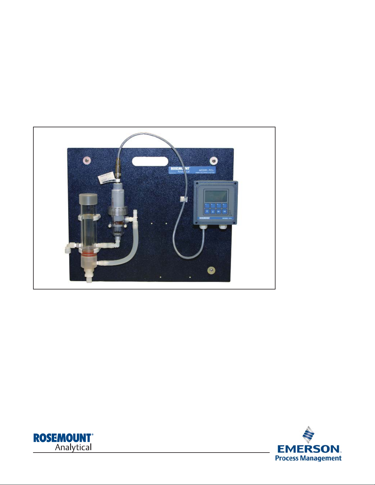
FCLi with 54eA Analyzer
Instruction Manual
PN 51-FCLi-54eA rev.B
March 2012
Page 2
This product generates, uses, and can radiate radio frequency
energy and thus can cause radio communication interference.
Improper installation, or operation, may increase such interfer-
ence. As temporarily permitted by regulation, this unit has not
been tested for compliance within the limits of Class A computing
devices, pursuant to Subpart J of Part 15, of FCC Rules, which
are designed to provide reasonable protection against such
interference. Operation of this equipment in a residential area
may cause interference, in which case the user at his own
expense, will be required to take whatever measures may be
required to correct the interference.
ESSENTIAL INSTRUCTIONS
READ THIS PAGE BEFORE PROCEEDING!
Your purchase from Rosemount Analytical, Inc. has
resulted in one of the finest instruments available for
your particular application. These instruments have
been designed, and tested to meet many national
and international standards. Experience indicates
that its performance is directly related to the quality
of the installation and knowledge of the user in operating and maintaining the instrument. To ensure
their continued operation to the design specifications, personnel should read this manual thoroughly
before proceeding with installation, commissioning,
operation, and maintenance of this instrument. If
this equipment is used in a manner not specified by
the manufacturer, the protection provided by it
against hazards may be impaired.
• Failure to follow the proper instructions may
cause any one of the following situations to
occur: Loss of life; personal injury; property damage; damage to this instrument; and warranty
invalidation.
• Ensure that you have received the correct model
and options from your purchase order. Verify that
this manual covers your model and options. If
not, call 1-800-854-8257 or 949-757-8500 to
request correct manual.
• For clarification of instructions, contact your
Rosemount representative.
• Follow all warnings, cautions, and instructions
marked on and supplied with the product.
• Use only qualified personnel to install, operate,
update, program and maintain the product.
• Educate your personnel in the proper installation,
operation, and maintenance of the product.
• Install equipment as specified in the Installation
section of this manual. Follow appropriate local
and national codes. Only connect the product to
electrical and pressure sources specified in this
manual.
• Use only factory documented components for
repair. Tampering or unauthorized substitution of
parts and procedures can affect the performance
and cause unsafe operation of your process.
• All equipment doors must be closed and protective covers must be in place unless qualified personnel are performing maintenance.
• If this equipment is used in a manner not specified by the manufacturer, the protection provided
by it against hazards may be impaired.
Equipment protected throughout by double insulation.
• Installation of cable connections and servicing of this product
require access to shock hazard voltage levels.
• Main power and relay contacts wired to separate power
source must be disconnected before servicing.
• Do not operate or energize instrument with case open!
• Signal wiring connected in this box must be rated at least
240 V.
• Non-metallic cable strain reliefs do not provide grounding
between conduit connections! Use grounding type bushings
and jumper wires.
• Unused cable conduit entries must be securely sealed by
non-flammable closures to provide enclosure integrity in
compliance with personal safety and environmental protection
requirements. Unused conduit openings must be sealed with
NEMA 4X or IP65 conduit plugs to maintain the ingress
protection rating (NEMA 4X).
• Electrical installation must be in accordance with the National
Electrical Code (ANSI/NFPA-70) and/or any other applicable
national or local codes.
• Operate only with front and rear panels fastened and in place
over terminal area.
• Safety and performance require that this instrument be
connected and properly grounded through a three-wire
power source.
• Proper relay use and configuration is the responsibility of the
user.
This product is not intended for use in the light industrial,
residential or commercial environments per the instrument’s certification to EN50081-2.
Emerson Process Management
2400 Barranca Parkway
Irvine, CA 92606 USA
Tel: (949) 757-8500
Fax: (949) 474-7250
http://www.rosemountanalytical.com
© Rosemount Analytical Inc. 2012
WARNING
RISK OF ELECTRICAL SHOCK
WARNING
CAUTION
Page 3

About This Document
This manual contains instructions for installation and operation of the FCLi-54eA
The following list provides notes concerning all revisions of this document.
Rev. Level
Date Notes
A 4/08 This is the initial release of the product manual. The manual has been
reformatted to reflect the Emerson documentation style and updated to
reflect any changes in the product offering.
B 03/12 Update addresses - mail and web and DNV certification notice
Page 4

i
MODEL FCLI-54eA TABLE OF CONTENTS
FCLi-54eA
TABLE OF CONTENTS
Section Title Page
1.0 DESCRIPTION AND SPECIFICATIONS ................................................................ 1
1.1 Applications and Features ..................................................................................... 1
1.2 Specifications-General............................................................................................. 2
1.3 Ordering Information ................................................................................................ 3
2.0 INSTALLATION ....................................................................................................... 5
2.1 Unpacking and Inspection........................................................................................ 5
2.2 Installation................................................................................................................ 5
3.0 WIRING.................................................................................................................... 9
3.1 General .................................................................................................................... 9
3.2 Power, Alarm, and Output Wiring............................................................................. 9
4.0 DISPLAY AND OPERATION................................................................................... 13
4.1 General Description ................................................................................................. 13
4.2 Display ..................................................................................................................... 13
4.3 Key Functions and Controls..................................................................................... 13
4.4 Alarm Status............................................................................................................. 13
5.0 PROGRAMMING THE ANALYZER ........................................................................ 15
5.1 Changing Alarm Setpoints ....................................................................................... 21
5.2 Ranging the Outputs ................................................................................................ 22
5.3 Test Outputs and Alarms.......................................................................................... 23
5.4 Chosing Display Options.......................................................................................... 24-25
5.5 Changing Output Parameters .................................................................................. 26-27
5.6 Changing Alarm Parameters .................................................................................... 28-31
5.7 Configuring the pH Measurement ............................................................................ 32
5.8 Temperature Compensation and Temperature Units ............................................... 33
5.9 Noise Reduction....................................................................................................... 34
5.10 Main Sensor Calibration Parameters ....................................................................... 35
5.11 Security ....................................................................................................................36
5.12 Analyzer Mode Priority............................................................................................. 37
6.0 CALIBRATION - TEMPERATURE .......................................................................... 39
6.1 Introduction .............................................................................................................. 39
6.2 Temperature Calibration........................................................................................... 40
Page 5

Section Title Page
7.0 CALIBRATION CHLORINE .................................................................................... 41
7.1 Introduction .............................................................................................................. 41
7.2 Zeroing the Sensor .................................................................................................. 42
7.3 Full Scale Calibration ............................................................................................... 43
7.4 Dual Slope Calibration ............................................................................................. 44
8.0 CALIBRATION - CURRENT OUTPUTS ................................................................. 47
8.1 Introduction .............................................................................................................. 47
8.2 Trimming the Outputs............................................................................................... 47
9.0 MAINTENANCE ..................................................................................................... 49
9.1 Analyzer ................................................................................................................... 49
9.2 Chlorine Sensor ....................................................................................................... 50
9.3 Constant Head Flow Controller................................................................................ 52
10.0 TROUBLESHOOTING ........................................................................................... 55
10.1 Overview .................................................................................................................. 55
10.2 Troubleshooting When a Fault Message is Showing............................................... 55
10.3 Troubleshooting When No Fault Message is Showing - Temperature ..................... 56
10.4 Troubleshooting When No Error Message is Showing - Chlorine............................ 56
10.5 Troubleshooting When No Error Message is Showing - General ............................ 59
10.6 Simulating Inputs - Chlorine..................................................................................... 59
10.7 Simulating Inputs - Temperature............................................................................... 60
LIST OF TABLES
Number Title Page
5.1 Program Settings List ............................................................................................... 15-17
5.2 Controller Mode Priority Chart.................................................................................. 37
10.2 Troubleshooting When a Fault Message is Showing ............................................... 55
10.4 Troubleshooting When No Error Message is Showing - Chlorine ............................ 56
10.5 Troubleshooting When No Error Message is Showing - General............................. 59
MODEL FCLi-54eA TABLE OF CONTENTS
TABLE OF CONTENTS CONT’D
ii
Page 6

LIST OF FIGURES
Number Title Page
2-1 Chlorine Sensor Parts .............................................................................................. 7
2-2 Model FCLi-01-230................................................................................................... 8
3-1 Power Input and Relay Output Wiring for Model 54eA ............................................ 10
3-2 Wiring Label .................................................................................................... 11
3-3 Wiring Sensor to Model 54eA Analyzer ...................................................................... 11
4-1 Main Display Screen ................................................................................................ 13
5-1 Menu Tree for the 54eA Controller .......................................................................... 18-20
5-2 Low Alarm ................................................................................................................ 30
5-3 High Alarm................................................................................................................ 30
5-4 Interval Timer............................................................................................................ 31
7-1 Sensor Current as a Function of Free Chlorine Concentration ................................ 41
7-2 Dual Slope Calibration.............................................................................................. 44
9-1 Chlorine Sensor Parts ............................................................................................. 51
9-2 Replacement Parts for the Flow Controller Assembly.............................................. 53
10-3 Three-Wire RTD Configuration................................................................................. 60
10-4 Simulating RTD Inputs.............................................................................................. 60
iii
Page 7

Model FCLi-54eA SECTION 1.0
DESCRIPTION AND SPECIFICATIONS
SECTION 1.0.
DESCRIPTION AND SPECIFICATIONS
1
• COMPLETE SYSTEM INCLUDES sensor, connecting cable, analyzer, and flow controller
• SENSOR RESPONSE IS PRACTICALLY INDEPENDENT of pH between pH 6 and 10
• NO REAGENTS
• NO AUXILIARY pH ELECTRODE
• VARIOPOL QUICK-DISCONNECT FITTINGS makes sensor replacement easy
1.1 APPLICATIONS AND FEATURES
TheFCLi free chlorine system is intended for the
determination of free chlorine (hypochlorous acid plus
hypochlorite ion) in fresh water. Unlike other free chlorine analyzers, the FCLi does not use expensive sample conditioning systems or messy reagents to control
pH. Nor, does it require an auxiliary pH sensor for pH
correction. Instead, the pH adjustment takes place
inside the sensor, producing a signal that changes
less than 4% per unit change in pH between pH 6 and
10. Below pH 6.5 the change is less than 1%. The linear range of the sensor is 0 to 20 ppm (mg/L).
The FCLi is not intended for the determination of total
or combined chlorine (like monochloramine). Nor, can
the FCLi be used for the determination of chlorine in
seawater.
The FCLi uses a three electrode, membrane-covered
amperometric sensor. The sensor consists of a
hydrophilic membrane stretched over a gold mesh
cathode. A silver/silver chloride reference electrode
and an external copper auxiliary electrode complete
the circuit. The fill solution is saturated succinic acid
slurry. During operation, an electrochemical reaction,
driven by the polarizing voltage, consumes free chlorine at the cathode surface. The auxiliary electrode
provides the electrons for the cathode reaction, and
a current proportional to the reaction rate flows
between the electrodes. Because the concentration of
chlorine at the cathode is zero, free chlorine in the
sample continuously diffuses through the membrane
and is destroyed at the cathode. Thus, the cathode
current is proportional to the diffusion rate, which is
proportional to the concentration of free chlorine in the
sample.
The FCLi sensor requires neither sample pretreatment
nor pH correction. All amperometric free chlorine
sensors generate a raw current that depends primarily
on the concentration of hypochlorous acid. Because
the fraction of free chlorine present as hypochlorous
acid is a function of pH, readings will be in error if the
sample pH changes from the value it had during
calibration. To correct for pH changes, some manufacturers treat the sample with acid to convert hypochlorite to hypochlorous acid. Others continuously
measure the pH and use the pH value to correct the
chlorine sensor reading. The FCLi is different. The
sensor uses a highly buffered acidic fill solution for
internal pH adjustment. The fill solution converts all
the free chlorine entering the sensor as well as much
of the free chlorine at the outside surface of the membrane into hypochlorous acid. Thus, the sensor
response is practically independent of pH.
Maintenance is fast and easy. Replacing a membrane
requires no special tools or fixtures. A screw cap holds
the pre-tensioned membrane in place. Replacing the
membrane and fill slurry takes only a few minutes.
The FCLi includes the easy-to-use Model 54eA analyzer. The analyzer features two fully programmable 420 mA analog outputs and three alarm relays.
Programming and calibration is simple and intuitive.
The large backlit, display allows the user to read chlorine at a single glance.
Valves, rotameters, and pressure regulators to control
sample flow are things of the past with the FCLi. A
constant head overflow sampler ensures the correct
flow to the sensor no matter how much the sample
flow or pressure changes. To eliminate wiring hassles,
quick disconnect Variopol cable is standard.
Stable free chlorine standards do not exist. The chlorine
sensor must be calibrated using the results of a
laboratory test on a grab sample.
Page 8
1.2 SPECIFICATIONS — GENERAL
Sample requirements:
Pressure: 3 to 65 psig (122 to 549 kPa abs)
A check valve in the inlet opens at 3 psig (122
kPa abs). If the check valve is removed, minimum pressure is 1 psig (108 kpa abs).
Temperature: 32 to 122°F (0 to 50°)
Minimum Flow: 2 gal/hr (7.6 L/hr)
Maximum flow: 80 gal/hr (303 L/hr); high flow
causes the overflow tube to back up.
Sample Conductivity: >10 µS/cm
Process connection: 1/4-in OD tubing compression
fitting (can be removed and replaced with barbed
fitting for soft tubing).
Drain connection: 3/4-in barbed fitting. Sample must
drain to open atmosphere.
Wetted parts:
Overflow sampler: acrylic, polycarbonate,
polyester, Kynar1, nylon, silicone
Chlorine sensor: PVC, Viton2, silicone, polyether-
sulfone, polyester, and copper
pH sensor: Tefzel2, Viton, glass, ceramic
Response time to step change in chlorine concen-
tration: <120 sec to 90% of final reading for inlet
sample flow of 2 gph (7.6 L/hr).
Weight/shipping weight:
Model FCLi-01: 10 lb/13 lb (4.5 kg/6.0 kg)
Model FCLi-02: 11 lb/14 lb (5.0 kg/6.5 kg)
[rounded to the nearest 1 lb. (0.5 kg)]
SPECIFICATIONS — SENSOR
Free chlorine range: 0 to 20 ppm as Cl2. For higher
ranges, consult the factory.
Accuracy: Accuracy depends on the accuracy of the
chemical test used to calibrate the sensor
Linearity (0-20 ppm): 1% per IEC 60746
Linearity (0-2 ppm): ±0.05 ppm following calibration
at 2 ppm
Sensitivity to pH: Between pH 6.5 and 10, sensor
signal changes <4% per unit change in pH. Below
pH 6.5 the change is
<1% per unit change in pH.
Interferences: Monochloramine, dichloramine, and
permanganate
Electrolyte life: 3 months (approx.)
SPECIFICATIONS — 54eA ANALYZER
Case: Epoxy-painted cast aluminum, NEMA4X (IP65).
Display: Three-line, back-lit, dot matrix LCD. First line is
measurement reading. Second line is temperature
and current output. Third line is user-selectable.
Character heights: 1st line - 0.6 in. (16 mm) , 2nd
and 3rd lines - 0.3 in. (7 mm) .
Ambient Temperature and Humidity: 0 to 50°C (32
to 122°F). 95% (maximum) non-condensing.
Analyzer can be operated between -20 and 60°C
(-4 to 140°F) with some degradation in display
quality.
Power: 100-127 Vac ± 10%, 50/60 Hz ± 6%, 8 W
200-253 Vac ± 10%, 50/60 Hz ± 6%, 8 W
RFI/EMI: EN-61326
LVD: EN-61010-1
Outputs: Two 4-20 mA or 0-20 mA isolated outputs.
Continuously adjustable. Output dampening
is user-selectable. Maximum load at 115/230
Vac is 600Ω. Maximum load at 100/200 Vac is
550Ω.
Alarms: Three alarm relays for chlorine or tempera-
ture. Fully programmable. Fourth relay for
analyzer/sensor fault.
Relay: Relays 1-3: Form A, SPST, epoxy sealed
Relay 4: Form C, SPDT, epoxy sealed
2
MODEL FCLi-54eA SECTION 1.0
DESCRIPTION AND SPECIFICATIONS
1
Kynar is a registered trademark of Elf Atochem North America.
2
Viton and Tefzel are registered trademarks of DuPont
Performance Eastomers.
Resistive Inductive
28 Vdc 5.0 3.0
115 Vac 5.0 3.0
230 Vac 5.0 1.5
Page 9
3
1.3 ORDERING INFORMATION
Model FCLi Free Chlorine Measuring System. The FCLi is a complete system for the determination of free
chlorine in aqueous samples. It consists of a sensor, analyzer, and constant head flow controller. All components
are mounted on a backplate. Three replacement membranes and enough electrolyte chemicals to fill the sensor
three times are shipped with each sensor.
MODEL FCLi FREE CHLORINE MEASURING SYSTEM
FCLi-01 -230 EXAMPLE
MODEL FCLi-54eA SECTION 1.0
DESCRIPTION AND SPECIFICATIONS
CODE pH CORRECTION (required selection)
01 Without pH sensor
CODE ANALYZER
230
54eA-01
ANALYZER MODEL DESCRIPTION
54eA-01 54eA analyzer 115/230 Vac
SENSOR MODEL DESCRIPTION
498CL-01-VP pH-independent free chlorine sensor with Variopol connector
SENSOR CABLE DESCRIPTION
23645-13 Interconnecting cable, Variopol for 498CL sensor, 4 ft
COMPONENT PARTS
PART # DESCRIPTION
9240048-00 Tag, stainless steel (specify marking)
ACCESSORIES
SPARE PARTS
PART # DESCRIPTION
33970-00
Fill plug
33968-00
Membrane retainer
9550094
O-ring, 2-014, Viton
®
23501-10 pH-independent free chlorine membrane assembly, includes one membrane assembly
and O-ring
23502-10 pH-independent free chlorine membrane assembly, includes three membrane assem-
blies and three O-rings
24146-00
pH-independent free chlorine sensor electrolyte kit, includes three bottles of saturated
succinic acid and three bottles of succinic acid crystals
Page 10

This page left blank intentionally
MODEL FCLi-54eA SECTION 1.0
DESCRIPTION AND SPECIFICATIONS
4
Page 11
SECTION 2.0.
INSTALLATION
MODEL FCLi-54eA SECTION 2.0
INSTALLATION
2.1 UNPACKING AND INSPECTION
Inspect the shipping container. If it is damaged, contact the shipper immediately for instructions. Save the box. If
there is no apparent damage, unpack the container. Be sure all items shown on the packing list are present. If
items are missing, notify Rosemount Analytical immediately.
2.1.1 FCLi-01-230 (free chlorine without pH sensor)
Model consists of the following items mounted on a back plate.
1. The 54eA-01 analyzer with sensor cable attached.
2. Constant head overflow sampler with flow cell for chlorine sensor.
The free chlorine sensor (498CL-01-VP) is in a separate package. The sensor is shipped with three membrane
assemblies and enough electrolyte chemicals to fill the sensor three times.
2.2 INSTALLATION
2.2.1 General Information
1. Although the system is suitable for outdoor use, do not install it in direct sunlight or in areas of extreme
temperature.
2. To keep the analyzer enclosure watertight, install plugs (provided) in the unused cable openings.
3. Install the system in an area where vibrations and electromagnetic and radio frequency interference are
minimized or absent.
4. Be sure there is easy access to the analyzer and sensors.
2.2.2 Sample Requirements
Be sure the sample meets the following requirements:
1. Temperature: 32 to 122ºF (0 to 50ºC)
2. Pressure: 3 to 65 psig (122 to 549 kPa abs)
3. Minimum flow: 2 gal/hr (7.6 L/hr)
5
The FCLi free-chlorine analyzer is NOT suitable for
use in hazardous areas.
CAUTION
Page 12

6
MODEL FCLi-54eA SECTION 2.0
INSTALLATION
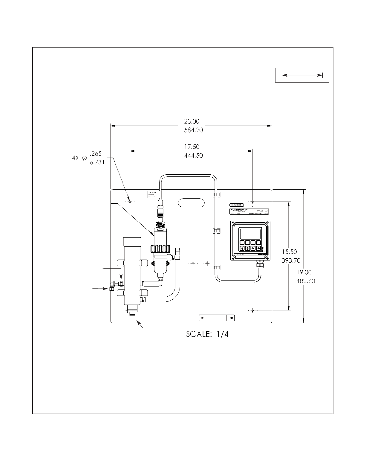
2.2.3 Mounting and Making Inlet and Drain Connections
The FCLi is intended for wall mounting only. Refer to Figure 2-2 for details.
A 1/4-inch OD tubing compression fitting is provided for the sample inlet. If desired, the compression fitting can
be removed and replaced with a barbed fitting. Do not remove the check valve. The threads are 1/4-inch FNPT.
The sample drains through a 3/4-inch barbed fitting. Attach a piece of soft tubing to the fitting and allow the waste
to drain to open atmosphere. Do not restrict the drain line.
Remove the foam packing insert between the outer tube and the inner overflow tube. Adjust the sample flow
until the water level is even with the central overflow tube and excess water is flowing down the tube. Confirm that
sample is flowing through the flow cell.
2.2.4 Electrical Connections
Refer to Section 3.0 for wiring details.
2.2.5 Installing the Sensor
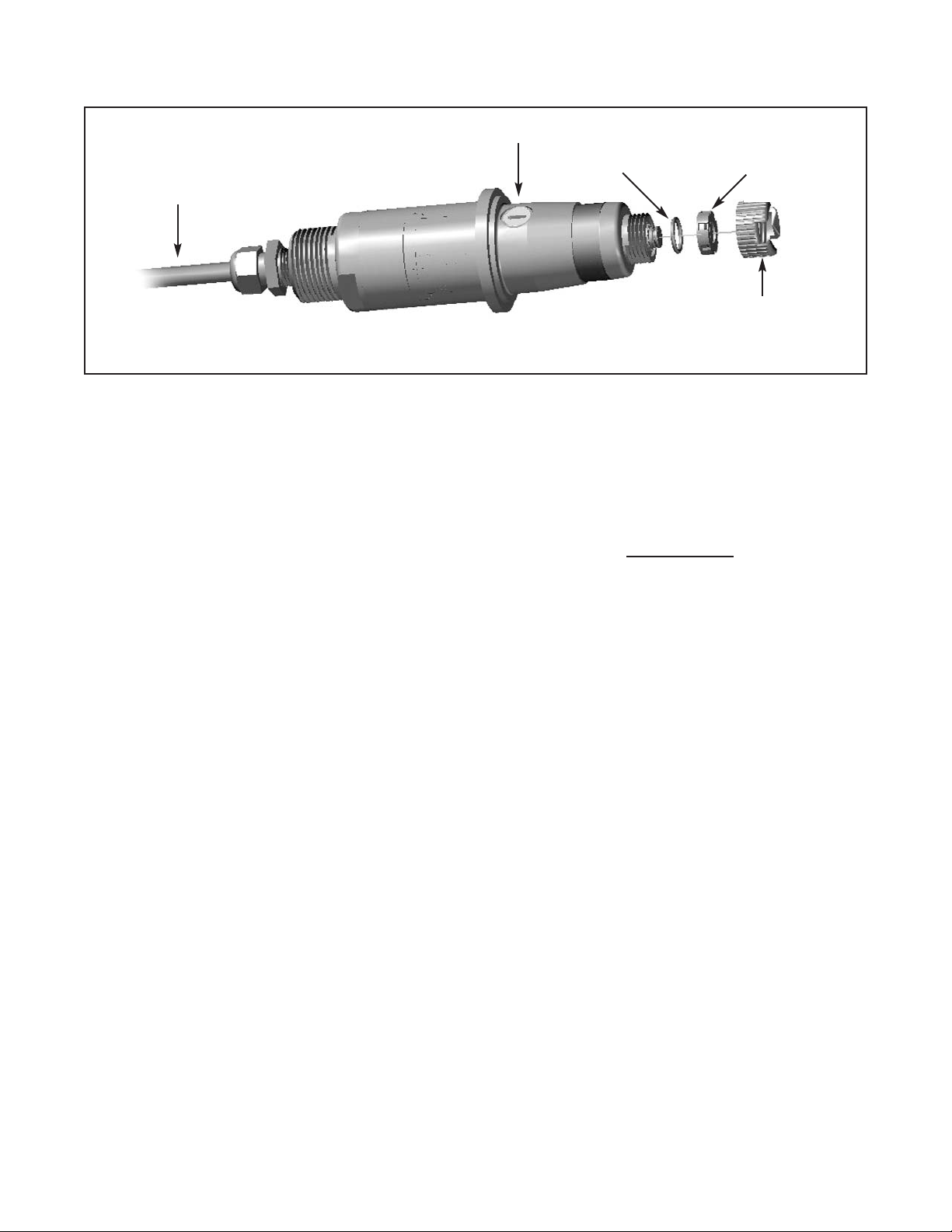
1. The chlorine sensor leaves the factory with a shipping membrane in place. The shipping membrane
must be removed and replaced with the chlorine membrane before putting the sensor in service. The
chlorine membrane is in a plastic bag attached to the sensor. Do not remove the shipping membrane
until you are ready to put the sensor in service.
a. Remove the red protective cap from the end of the sensor.
b. Holding the membrane end pointing up (cable connector end pointing down), unscrew the retainer cap
and remove the shipping membrane. See Figure 2.1. It is not necessary to remove the O-ring. Save the
shipping membrane. It should be reinstalled on the sensor when the sensor is not in use.
c. Still holding the membrane end pointing up, install the chlorine membrane. The chlorine membrane is in
the plastic bag attached to the sensor. Screw the retainer back in place.
2. Install the sensor in the flow cell as shown in Figure 2.2. The chlorine sensor sits in the flow cell and is held
in place by the union nut. Be sure to slip the union nut over the sensor before connecting the cable to the
sensor.
3. The Model FCLi is provided with sensor cable pre-wired to the analyzer. The terminal end of the sensor is
keyed to ensure proper mating with the cable receptacle. Once the key has slid into the mating slot, tighten
the connection by turning the knurled ring clockwise.
NOTE
Once power has been applied to the analyzer, configure it to measure free chlorine. See
section 5.4 for details. Do not connect the sensor to the cable until the analyzer has been
properly configured.
NOTE
Do not connect the sensor to the cable until the analyzer has been
configured to measure free chlorine. See section 5.4 for details.
Page 13
7
Model FCLi-54eA SECTION 2.0
INSTALLATION
FIGURE 2-1. Chlorine Sensor Parts
fill plug
o-ring
membrane
assembly
membrane
retainer cap
cable
end
NOTE
Once the chlorine sensor has been connected to the analyzer and power applied, the sensor must be
placed in the flow cell filled with water.
Generally, the sensor must be in a continously flowing sample. However, the sensor can tolerate loss of
sample flow for about four days as long as it remains immersed in water in the flow cell
. There is a check
valve in the sample inlet to prevent water from draining out of the flow cell.
If the sensor sits too long in a stagnant sample, copper ions from oxidation of the external copper
electrode can diffuse into the sensor. Once inside the sensor the copper undergoes an electrochemical
reaction that greatly increases the background current and can potentially damage the sensor. See
step 2 in Section 7.2 for more information.
Do not store the chlorine sensor in air. The membrane will dry out. If the membrane dries out, it must be
replaced.
Page 14
8
MODEL FCLi-54eA SECTION 2.0
INSTALLATION
FIGURE 2-2. Model FCLi-01-230
CHECK VALVE
CHLORINE SENSOR
INLET
DRAIN
INCH
MILLIMETER
Page 15
SECTION 3.0.
WIRING
MODEL FCLi-54eA SECTION 3.0
WIRING
9
3.1 GENERAL
WARNING
Electrical installation must conform to the National Electrical Code, all state and local codes, and all plant
codes and standards for electrical equipment. Electrical installation and wiring must be done by qualified
personnel.
The five holes in the bottom of the instrument case accept 1/2-in. strain relief connectors or conduit fittings. The
rear openings are for power and alarm relay wiring. The left front opening is for sensor wiring (already installed)
and the right front opening is for analog output wiring. Seal unused openings with conduit plugs.
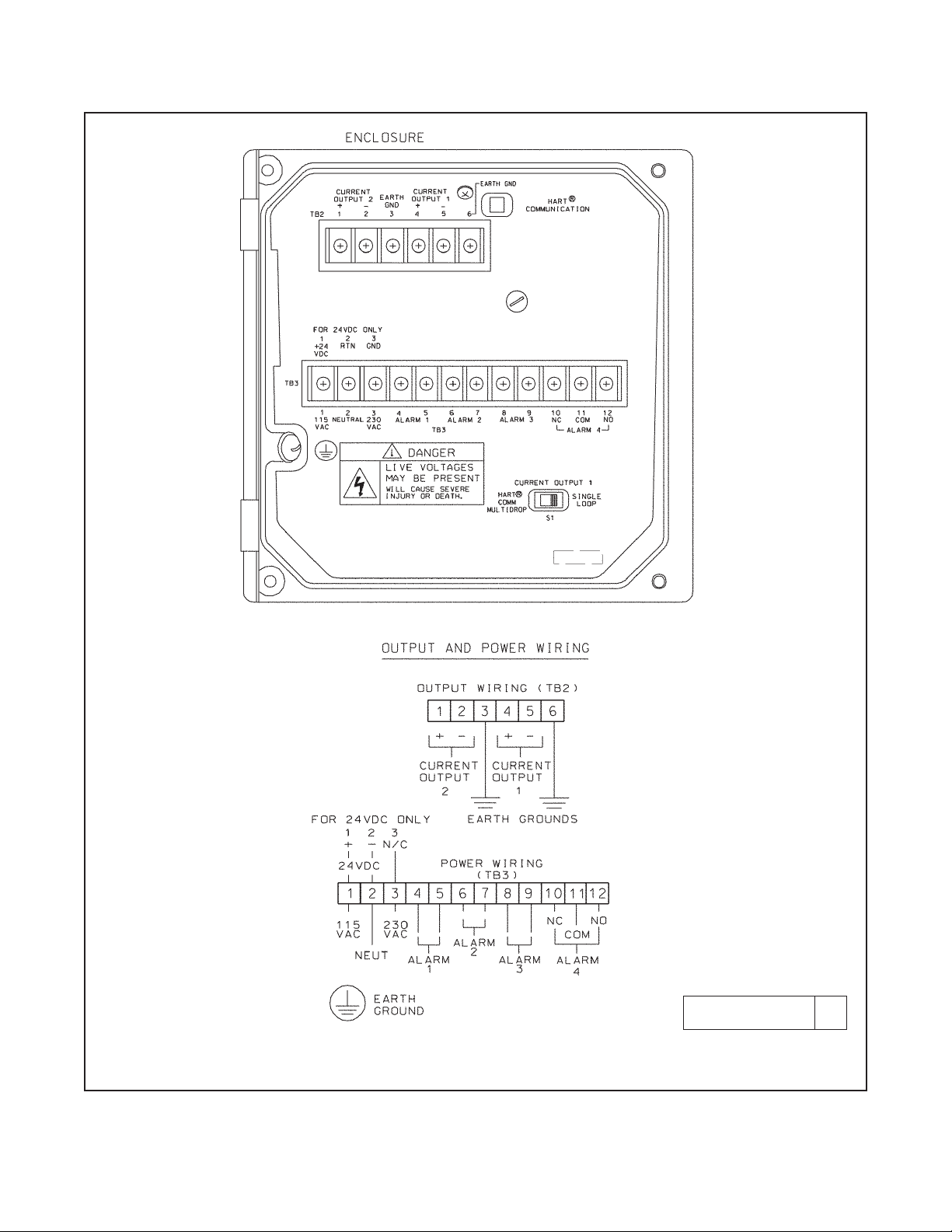
3.2 POWER, ALARM, AND OUTPUT WIRING
Refer to Figure 3-1. Make power and alarm connections on TB3. Make analog output wiring connections on TB2. For
access to power and alarm terminals, loosen the screw holding the protective cover in place and remove the cover.
Alarm contacts are dry (i.e., not powered) and are normally open. Refer to Section 1.0 for relay specifications.
For best EMI/RFI protection, shield the output cable and enclose it in an earth-grounded, rigid, metal conduit.
Connect the outer shield of the output cable to the earth ground connection on TB2 (see Figure 3-1).
Keep sensor and output signal wiring separate from power wiring. Do not run sensor and power cables in the same
conduit or close together in a cable tray.
AC wiring must be 14 gauge or greater. Be sure to connect earth ground from the power cable to the nearby
ground lug. A good earth ground is necessary for proper operation of the controller. Provide a switch or breaker to
disconnect the analyzer from the main power supply. Install the switch or breaker near the analyzer and label it as
the disconnecting device.
NOTE
The 54eA analyzer leaves the factory configured to measure dissolved oxygen, not free chlorine.
Before connecting the sensor to the cable, configure the analyzer to measure free chlorine. See
section 5.4
Live voltages may be present. Will
cause severe injury or death
DANGER
WARNING
RISK OF ELECTRICAL SHOCK
AC connections and grounding must comply with UL
508 or local electrical code. DO NOT apply power to
the analyzer until all electrical connections are verified and secure.
WARNING
Page 16
MODEL FCLi-54eA SECTION 3.0
WIRING
10
FIGURE 3-1. Power Input and Relay Output Wiring for 54eA
DWG. NO. REV.
454EPH02 D
Page 17
11
MODEL FCLi-54eA SECTION 3.0
WIRING
FIGURE 3-2. Wiring Label
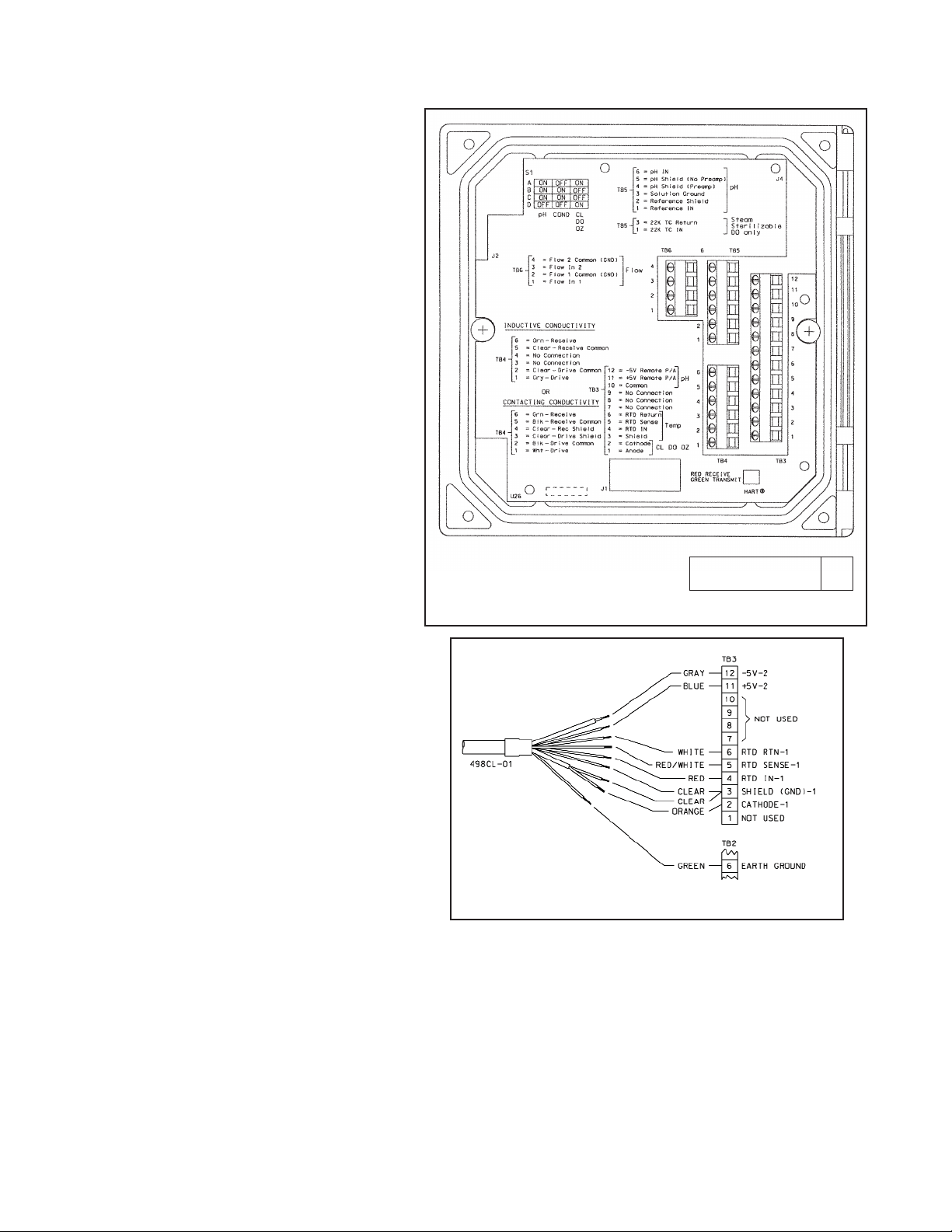
3.3 SENSOR WIRING
3.3.1 General
The wiring label is a general purpose label. It
has wiring information concerning other
sensors, for example, contacting and inductive
conductivity sensors, that can be used with the
54e instrument platform. The FCLi is provided
with sensor cable pre-wired to the analyzer. If
it is necessary to replace the cable, refer to
Figures 3-2 (wiring label) and 3-3 (wiring diagram).
DWG. NO. REV.
40054e03 A
FIGURE 3-3. Wiring Sensor to Model 54eA Analyzer
Page 18

This page left blank intentionally
12
MODEL FCLi-54eA SECTION 3.0
WIRING
Page 19

13
MODEL FCLi-54eA SECTION 4.0
DISPLAY AND OPERATION
SECTION 4.0
DISPLAY AND OPERATION
4.1 GENERAL DESCRIPTION
The 54eA analyzer is a single input, dual output instrument.
4.2 DISPLAY
Figure 4-2 shows the main display.
4.3 KEY FUNCTIONS AND CONTROLS
The keys labeled F1, F2, F3, and F4 are multi-function.
The function appears in the main display just above the
key. For example, F1 is usually labeled Exit and F4
may be labeled Edit, Save, or Enter.
1. To enter the main menu, press any key.
2. Use the é and ê keys to move the cursor to the
desired sub-menu. The position of the cursor is
shown in reverse video.
NOTE
When the last item of a menu has been
reached, the cursor will be on the third line
of the display. If the cursor is on the second
line of the display more items remain.
Continue pressing the ê key.
3. Press Enter (F4) to access a sub-menu or an item
in a sub-menu.
4. To change a number or a setting press Edit (F4).
The display will change to show the cursor on the
first digit or on a + or - sign. Use the é and ê keys
to increase or decrease a digit or to toggle the +
and - signs. Use the ç and è keys to move the
cursor left and right.
5. If an entire number or a word is highlighted, use the
é and ê keys to scroll through the list of choices.
6. To store a number or setting in memory, press
Save (F4).
7. To leave without storing changes, press Esc (F3).
8. To leave and return to the previous screen, press
Exit (F1).
9. To end a calibration step and leave the previous
calibration in place, press Abort (F1).
10. Occasionally, information screens will appear. To
leave the information screen and move to the next
screen press Cont (F3).
4.4 ALARM STATUS
Green LEDs (labeled 1, 2, and 3) indicate when alarm
relays 1, 2, and 3 are energized. The fourth relay indicates a fault condition. When a fault occurs, the red
LED (labeled FAIL) lights up, a descriptive error message appears, and the outputs and alarm relays act as
described in Section 5.6 under fault value.
The red LED also indicates when the interval timer
routine is activated and when the time limit has been
reached on a feed limit timer. For more information on
these subjects, see Section 5.6.
FIGURE 4-1. Main Display Screen
Chlorine is always displayed continuously in large
numerals. The temperature and output current are
always displayed on the second line of the main display.
The third line can be configured by the user. In the example, the third line shows the alarm setpoint and the raw
sensor current in nA.
1.00 ppm
26.2°C. 12.00 mA
AL1: 0.20ppm I: 340 nA
Page 20

This page left blank intentionally
14
MODEL FCLi-54eA SECTION 4.0
DISPLAY AND OPERATION
Page 21

15
SECTION 5.0
PROGRAMMING THE ANALYZER
MODEL FCLi-54eA SECTION 5.0
PROGRAMMING THE ANALYZER
The 54eA analyzer can be used to measure dissolved oxygen, ozone, total chlorine, and monochloramine in addition to free chlorine. It is configured at the factory to measure dissolved oxygen. Before connecting the sensor to
the cable, the analyzer must be configured to measure free chlorine. See section 5.4.
Figure 5-1 is an outline of the analyzer menu structure. Settings that do not apply to the measurement of free chlorine
are grayed out. Settings that apply to PID and TPC control and HART digital communications, features not
available in the analyzer option provided with the FCLi, are also grayed out.
Table 5-1 list the default settings and the choices available for each setting. Only the choices available for free
chlorine are shown.
TABLE 5-1. Program Settings List
Continued on the following page
ITEMS CHOICES FACTORY SETTINGS
A. Alarms setpoints (Section 5.1)
1. Alarm 1 (low action)
a. if chlorine -9999 to 9999 ppm 0 ppm
b. if temperature -5 to 130°C 0.1°C
2. Alarm 2 (high action)
a. if chlorine -9999 to 9999 ppm 20 ppm
b. if temperature -5 to 130°C 130°C
3. Alarm 3 See alarm 2 See alarm 2
B. Output ranging (Section 5.2)
1. Output 1 or 2: 4 mA setting
a. if chlorine -9999 to 9999 ppm 0 ppm
b. if temperature -5 to 130°C 0.1°C
2. Output 1 or 2: 20 mA setting
a. if chlorine -9999 to 9999 ppm 20 ppm
b. if temperature -5 to 130°C 130°C
C. Display options (Section 5.4)
1. Measurement Oxygen, ozone, free chlorine, total chlorine, monochloramine Oxygen
2. Temperature units °C or °F °C
3. Output 1 mA or % of full scale mA
4. Output 2 mA or % of full scale mA
5. Language English, Français, Español, Deutsch, Italiano English
6. Main display left See section 5.4 Sensor current
7. Main display right See section 5.4 Output 1 current
8. Display contrast 00-99 (darkest) 50
9. Test timeout On or off On
10. Timeout value 1 to 60 min 10 min
D Output parameters (Section 5.5)
1. Output 1 Control
a. Measurement Oxygen, chlorine, ozone, pH, or temperature Oxygen
b. Control Normal Normal
Page 22

16
MODEL FCLi-54eA SECTION 5.0
PROGRAMMING THE ANALYZER
ITEMS CHOICES FACTORY SETTINGS
D. Outputs (Section 5.5) (continued)
2. Output 1 Setup (normal)
a. Current 4-20 mA or 0-20 mA* 4-20 mA
b. Dampening 0-299 sec 0 sec
c. Hold mode Hold last value or go to fixed value Hold last value
d. Fixed hold value 0-22 mA 21 mA
e. Fault value 0-22 mA 22 mA
3. Output 2 See output 1 See output 1
4. Hold feature Enable, disable, or 20 min timeout Disable
E. Alarms parameters (Section 5.6)
1. Alarm 1 Control
a. Activation method Oxygen, chlorine, ozone, temperature, pH Oxygen
b. Control mode Normal Normal
2. Alarm 1 setup (normal)
a. Configuration Low, high, or off High
b. Hysteresis
if chlorine -9999 to 9999 ppm 0 ppm
if temperature 0 to 10°C 0.1°C
c. Delay time 0-99 sec 0 sec
d. Relay fault none, open, closed None
3. Alarm 2 Control
a. Activation method Oxygen, chlorine, monochloramine, ozone, temperature, pH Oxygen
b. Control mode Normal Normal
4. Alarm 2 setup (normal)
a. Configuration Low, high, or off Low
Rest of alarm 2 setup is the same as alarm 1
5. Alarm 3 control and setup is the same as alarm 1
6. Alarm 4 control
Alarm Fault or off Fault
7. Feed limit timer
a. Feed limit Disable, alarm 1, alarm 2, or alarm 3 Disable
b. Timeout value 0 to 10,800 sec 600 sec
8. Interval timer
a. Select alarm Disable, alarm 1, alarm 2, or alarm 3 Disable
b. Interval time 0 to 999.9 hr 24.0 hr
c. Repeats 1 to 60 1
d. On time 0 to 2999 sec 120 sec
e. Off time 0 to 2999 sec 1 sec
f. Recovery time 0 to 999 sec 600 sec
F. Temperature compensation (Section 5.8)
1. Temperature compensation Auto or manual Auto
2. Manual temperature -15 to 130°C 25°C
TABLE 5-1. Program Settings List (continued)
Continued on the following page
Page 23

17
MODEL FCLi-54eA SECTION 5.0
PROGRAMMING THE ANALYZER
TABLE 5-1. Program Settings List (continued)
ITEMS CHOICES FACTORY SETTINGS
G. Noise Reduction (section 5.9)
Noise rejection 50 or 60 Hz 60 Hz
H. Main sensor calibration (Section 5.10)
1. Stabilize reading (Chlorine) 0 to 999 ppm 0.05 ppm
2. Stabilize time 0 - 30 sec 10 sec
3. Sensor zero stabilization value
4. Dual range calibration Enable or disable disable
I. Security (Section 5.11)
1. Lock all 000-999 (000 disables) 000
2. Lock program 000-999 (000 disables) 000
3. Lock configuration 000-999 (000 disables) 000
Page 24

18
MODEL FCLi-54eA SECTION 5.0
PROGRAMMING THE ANALYZER
FIGURE 5-1. Menu Tree for the 54eA Controller
Calibrate
Program (see page 19)
Diagnostic Variables
Main
Menu
Calibrate main sensor
Zero main sensor
Adjust temperature
Calibrate pH
Slope
Buffer calibration
Standardize
Main measurement
Main sensor current
Sensitivity (µA/ppm)
Zero current
pH reading
pH mV reading
pH slope (mV/pH)
pH offset
Barometric pressure
Glass impedance
Noise rejection
Software version
Device ID
Output trim
Page 25

19
MODEL FCLi-54eA SECTION 5.0
PROGRAMMING THE ANALYZER
Program
Calibrate (see page 18)
Diagnostic Variable (see page 20)
Main
Menu
Alarms 1, 2, and 3 setpoints
4 mA or 0 mA
20 mA
Present output current
Alarm Setpoints
Output setpoints
Test output 1 or 2
Test alarm 1, 2, 3, or 4
Simulated tests
Configure
Display
Main
Sensor
Oxygen
Free Chlorine
Total Chlorine
Monochloramine
Ozone
Outputs
Output 1 and 2
control
Measurement: main snr, pH, temp.
Control mode: normal, PID
Output 1 and 2
setup
Range (0-20 or 4-20 mA)
Dampen*
Hold - keep last value
Hold - go to specified value
Fault
Setpoint, proportional, integral
Derivative**
Hold feature setup
*Normal only
**PID only
Alarms
Alarm 1, 2, & 3
control
Measurement: main snr, pH, temp.
Control mode: normal, TPC
Alarm 1, 2, & 3
setup
Alarm: High, low, or off*
Setpoint
Hysteresis*
Delay*
Time period, URV, LRV**
Relay default
Interval timer
Timer: Alarm 1, 2, or 3 or disable
Interval
Repeats
On time
Off time
Recovery time
Alarm 4 setup
Feed limit timer
Feed limit: Alarm 1, 2, or 3 or disable
Timeout
*Normal only **TPC only
Continued on page 20
FIGURE 5-1. Menu Tree for the 54eA Controller
(continued)
Sensor type and manufac.
Units: ppm, ppb, % sat
°C or °F
Output 1 (mA or %FS)
Output 2 (mA or %FS)
Language
Line 3 display
Display contrast
Timeout (on or off)
Timeout - limit
Polling address
Page 26

20
MODEL FCLi-54eA SECTION 5.0
PROGRAMMING THE ANALYZER
FIGURE 5-1. Menu Tree for the 54eA Controller (continued)
Display (see page 22)
Outputs (see page 22)
Alarms (see page 22)
Program
Calibrate (see page 18)
Diagnostic Variable (see page 20)
Main
Menu
Alarm Setpoints (see page 19)
Output setpoints
(see page 19)
Simulated tests
(see page 19)
Configure
pH
(available with free
chlorine only)
Disable
Enable
pH
diagnostics
Diagnostics: on or off
Glass impedance high
Glass impedance low
Zero offset
Impedance temp comp: on or off
Temperature
Temperature comp: auto or manual
Units: °C or °F
Noise
Rejection
Noise rejection: 50 or 60 Hz
Barometric
Pressure
Measurement: Auto or manual
Units: mm Hg, kPa, atm, barg, in Hg
Main sensor cal
Stabilize conc’n
Stabilize time
Salinity (oxygen only)
Security
pH
calibration
Autocal: standard, manual,
Merck, Ingold, DIN 19267
Stabilize pH
Stabilize time
Temperature
coefficient
Temperature coeff
Operating isopotential
Sensor isopotential
Lock all
Lock program
Lock configure
(oxygen only)
Page 27

21
MODEL FCLi-54eA SECTION 5.0
PROGRAMMING THE ANALYZER
5.1 CHANGING ALARM SETPOINTS
2. Press any key to enter the main menu. Move the cursor to "Program"
and press Enter (F4).
3. Press Enter (F4).
4. Move the cursor to the desired alarm and press Enter (F4).
5. A screen like the one shown will appear. The alarm is a low alarm
and the setpoint is 0.00 ppm. Press Edit (F4). Use the arrow keys to
change the setpoint. Press Save (F4) to store the new value. Press
Exit (F1) to return to the screen in step 4. Choose a new alarm.
Alarm setpoints
Output setpoints
Simulate tests
Exit Enter
Alarm 1 setpoint
Alarm 2 setpoint
Alarm 3 setpoint
Exit Enter
Alarm Low : 0.000 ppm
Exit Edit
1. Before changing alarm setpoints, be sure that alarms are properly configured. See Section 5.6.
Page 28

22
MODEL FCLi-54eA SECTION 5.0
PROGRAMMING THE ANALYZER
5.2 RANGING THE OUTPUTS
2. Press any key to enter the main menu. Move the cursor to "Program"
and press Enter (F4).
3. Move the cursor to "Output setpoints" and press Enter (F4).
4. Move the cursor to the desired output and press Enter (F4).
5. This screen confirms that changes to output 1 are going to be made.
Use caution. Changes may degrade process control. Press Cont
(F3) to continue. Otherwise, press Abort (F1).
6. This screen shows the present settings for Output 1. If the output
was configured to be 0-20 mA, the first line will show "0mA" instead
of "4mA". The live current output is shown on the third line.
Move the cursor to the desired line and press Edit (F4). Use the
arrow keys to change the setpoint. Press Save (F4) to store the new
value.
Press Exit (F1) to return to the screen in step 4. Choose the other
output and continue.
Output 1 setpoints
Output 2 setpoints
Exit Enter
Alarm setpoints
Output setpoints
Simulated test
Exit Enter
CAUTION: Current
Output 1 will be
affected.
Abort Cont
1. Ranging the outputs means assigning values to the low (0 or 4 mA) and high (20 mA) outputs. Before rang-
ing the outputs, be sure the outputs are properly configured. See Section 5.5.
4 mA : 0.00 ppm
20 mA: 20.00 ppm
Output 1: 12.00 mA
Exit Edit
Page 29

23
MODEL FCLi-54eA SECTION 5.0
PROGRAMMING THE ANALYZER
5.3 TESTING OUTPUTS AND ALARMS
2. Press any key to enter the main menu. Move the cursor to "Program"
and press Enter (F4).
3. Move the cursor to "Simulated tests" and press Enter (F4).
4. Move the cursor to the desired output or alarm. Both outputs and all
four alarms can be tested. Press Enter (F4).
A screen will appear warning that the output or alarm will change.
Press Cont (F3) to continue. Press Abort (F1) to cancel the simulation.
5. This screen appears when an output is being simulated. To change
the simulation current, press Edit (F4). Use the arrow keys to change
the current to the desired value. Press Test (F4), then Esc (F3).
The simulated current will be generated for 10 minutes, then the output returns to normal operation. To change the timeout to a different
value see Section 5.4.
To end the simulation at any time, press Exit (F1).
6. This screen appears when an alarm is being simulated. To change
the state of the relay, press Edit (F4). Use the é or ê keys to change
from open to closed. Press Test (F4), then Esc (F3).
The alarm will be simulated for 10 minutes, then the alarm returns to
normal operation. To change the timeout to a different value, see
Section 5.4.
To end the simulation at any time, press Exit (F1).
Output setpoints
Simulated tests
Configure
Exit Enter
Test output 1
Test output 2
Test alarm 1
Exit Enter
Test output 1: 10.00 mA
Simulating output1
Exit Edit
Test alarm 1: Open
Simulating alarm1
Exit Edit
1. For testing purposes, the analyzer can be programmed to generate simulated outputs and to activate and
deactivate alarms.
Page 30

24
MODEL FCLi-54eA SECTION 5.0
PROGRAMMING THE ANALYZER
Output setpoints
Simulated tests
Configure
Exit Enter
5.4 CHOOSING DISPLAY OPTIONS
3. Press any key to enter the main menu. Move the cursor to "Program"
and press Enter (F4).
4. Move the cursor to "Configure" and press Enter (F4).
5. With the cursor on "Display", press Enter (F4).
6. A screen showing the present main measurement will appear. To
change the measurement from oxygen to free chlorine, press Edit
(F4), then use the é key to scroll through the choices until free
chlorine is showing. Press Save (F4) to store the setting.
A screen will appear warning that if the measurement is changed, the
analyzer will return to factory default settings. Press Cont (F3) to
continue. Press Abort (F1) to cancel the change.
7. Set the remainder of the display parameters. Use the é and ê keys
to choose the desired parameter. Then press Edit (F4). Use the é
key to move the cursor to the desired selection. Press Save (F4)
to store.
Display
Outputs
Alarms
Exit Enter
Measure : Oxygen
Sensor: RMT Standard
Meas units: ppm
Exit Edit
1. The Model 54eA analyzer is a versatile instrument that, in addition to free chlorine, can be used to measure
oxygen, ozone, and other forms of chlorine. The default measurement is oxygen. Before connecting the
sensor to the cable, the analyzer must be configured to measure free chlorine.
2. The display menu also lets the user customize the third line in the display, change timeout values, choose a
language other than English, and change the display contrast.
Temp units: °C
Output 1: mA
Output 2: mA
Exit Edit
Page 31

25
MODEL FCLi-54eA SECTION 5.0
PROGRAMMING THE ANALYZER
SECURITY CAUTION
The analyzer uses the timeout value to activate security. Once
the analyzer is unlocked by entering a security code, security will
not re-activate until a display timeout occurs. If timeout has been
turned off, security will never reactivate.
Language: English
Display left: I
Display right: Out 2
Exit Edit
Display contrast: 40
Timeout: On
Timeout value: 10 min
Exit Edit
5.4 CHOOSING DISPLAY OPTIONS (CONTINUED)
Temp units °C or °F
Output 1 mA or % of full scale
Output 2 mA or % of full scale
Language English, Français, Español, Deutsch, Italiano
Display left
sensor current (I), alarm 1 setpoint (no units),
alarm 3 setpoint (no units), or blank
Display right
sensor current (I), alarm 2 setpoint (no units), alarm
3 setpoint (no units), output 2, or blank
Display Contrast
00 (lightest)-99 (darkest); the display contrast
changes as the number changes
Timeout
Timeout returns the display from any other screen
to the main display if no key is pressed before the
timeout value is exceeded.
Timeout value
Page 32

26
MODEL FCLi-54eA SECTION 5.0
PROGRAMMING THE ANALYZER
5.5 CHANGING OUTPUT PARAMETERS
2. Press any key to enter the main menu. Move the cursor to "Program"
and press Enter (F4).
3. Move the cursor to "Configure" and press Enter (F4).
4. Move the cursor to "Outputs" and press Enter (F4).
5. Five menu headers relate to outputs. Each output has a control header
and a setup header. The fifth header allows the output hold feature to
be configured.
Always configure the control parameters BEFORE making
changes in the output setup.
To access a header, move the cursor to the desired header and press
Enter (F4).
6. Output Control Settings:
a. The cursor is on "Output Measurement" press Enter (F4).
b. Press Edit (F4).
c. Use the é key to scroll through the choices: "Process" or
"Temperature". "Process" means free chlorine. Press Save (F4)
to store the selection.
Output 1 control
Output 1 setup
Output 2 control
Exit Enter
Output Measurement
Control Mode
Exit Enter
Output : Process
Exit Edit
Display
Outputs
Alarms
Exit Enter
1. This section describes how to configure the analyzer outputs. Outputs can be configured to represent chlorine
or temperature.
Output setpoints
Simulated tests
Configure
Exit Enter
NOTE
There are no settings to make under “Control Mode.”
The 54eA analyzer supplied with the FCLi does not
have control features.
Page 33

27
MODEL FCLi-54eA SECTION 5.0
PROGRAMMING THE ANALYZER
5.5 CHANGING OUTPUT PARAMETERS (continued)
d. The display returns to the “Output: Process” screen. Press Exit
(F1) twice. The display returns to the “Control/Setup” screen
shown at left.
7. Output setup for normal outputs:
a. Move the cursor to the desired output setup and press Enter (F4).
b. Use the é and ê arrow keys to move the cursor to the desired
parameter. Press Edit (F4). Use the arrow keys to change the setting to the desired value and press Save(F4) to store the value.
Range: Choose 4-20 mA or 0-20 mA.
Dampen: Dampening averages the output current, thus smoothing
out a noisy reading. Higher values provide more smoothing but
increase the response time of the output.
Hold and Fixed Hold: If the analyzer is placed in hold, the
outputs will either remain at the last value or go to a fixed value
selected by the user. The fixed value must be between 0 and
22.00 mA.
Fault: If the analyzer detects a fault, the output will signal the fault
by going to a user-selected current between 0 and 22.00 mA.
For allowed values, see Table 5-1.
8. Hold setup.
a. Move the cursor to "Hold feature setup" and press Enter (F4).
b. Press Edit (F4). Use the é to scroll through the choices: "Disable
feature", "Enable feature", and "20 min timeout". If "20 min timeout" is selected, hold mode will automatically disengage after
being on for 20 minutes.
NOTE
Selecting "Enable hold" or "20-min timeout" does not put
the analyzer in hold. It only allows the user to put the
analyzer in hold when the controller is in calibrate mode.
9. Using hold.
If hold was enabled in step 8 above, the hold screen will appear as
soon as the user enters the Calibrate menu. To activate Hold, press
Edit (F4). Use the é key to change Off to On and press Save (F4).
"Hold Mode Activated" will be displayed. Outputs and relays will go to
the values programmed in step 7b.
Range : 4-20 mA
Dampen: 0 sec
Hold: Last Value
Exit Edit
Output 1 Control
Output 1 Setup
Output 2 Control
Exit Enter
Output 1 control
Output 1 setup
Output 2 control
Exit Enter
Output 2 control
Output 2 setup
Hold feature setup
Exit Enter
Page 34

28
MODEL FCLi-54eA SECTION 5.0
PROGRAMMING THE ANALYZER
"Hold Mode Activated" will continue to flash in the main display even
after the user has left the Calibrate menu. To deactivate hold, enter
the Calibrate menu and press Edit (F4). Use the é key to change On
to Off and press Save (F4). Press Exit (F1) twice to return to the main
display.
5.5 CHANGING OUTPUT PARAMETERS (continued)
5.6 CHANGING ALARM PARAMETERS
2. Press any key to enter the main menu. Move the cursor to "Program"
and press Enter (F4).
3. Move the cursor to "Configure" and press Enter (F4).
4. Move the cursor to "Alarms" and press Enter (F4).
5. Nine menu headers relate to alarms. Alarms 1, 2 and 3, each have a
control header and a setup header. Alarm 4 has only a setup header.
The eighth menu header is for configuring the feed limit timer, and the
ninth menu header is for configuring the interval timer.
Always configure the control parameters BEFORE making
changes in the alarm setup.
To access a header, move the cursor to the desired header and press
Enter (F4).
Alarm 1 control
Alarm 1 setup
Alarm 2 control
Exit Enter
Outputs
Alarms
pH
Exit Enter
Output setpoints
Simulated tests
Configure
Exit Enter
1. This section describes how to configure the analyzer alarms relays. Alarms 1, 2, and 3 can be assigned to
chlorine or temperature. In addition, alarm 1, 2, or 3 can be configured as a feed limit timer or as an interval
timer (see steps 9 and 10). Alarm 4 is always a fault alarm.
Page 35

29
MODEL FCLi-54eA SECTION 5.0
PROGRAMMING THE ANALYZER
Activation method
Control mode
Exit Enter
5.6 CHANGING ALARM PARAMETERS (continued)
6. Alarm Control Settings:
a. With the cursor on "Activation method" press Enter (F4).
b. To change the activation method, press Edit (F4). Use the é key
to scroll through the choices: "Process" or "Temperature".
"Process" means free chlorine. Press Save (F4) to store the
selection.
c. The display returns to the "Activate: Process" screen. Press Exit
(F1) twice. The display returns to the Control/Setup screen
shown at left.
7. Alarm setup for normal alarms:
a. Move the cursor to the desired alarm setup and press Enter (F4).
b. Use the é and ê keys to move the cursor to the desired param-
eter. Press Edit (F4). Use the arrow keys to change the setting to
the desired value and press Save (F4) to store the value. See the
Figures 5-2 and 5-3 for an explanation of terms: low alarm, high
alarm, hysteresis, and delay. See Table 5-1 for allowed values
and limits.
Relay default determines how the relay will operate if there is a
fault or the controller is in hold. Alarms can be forced on (Close),
off (Open), or remain unchanged (None).
Activate : Process
Exit Edit
Alarm : Low
Setpoint: 0.000 ppm
Hysteresis: 0.000 ppm
Exit Edit
Alarm 1 control
Alarm 1 setup
Alarm 2 control
Exit Enter
Alarm 1 control
Alarm 1 setup
Alarm 2 control
Exit Enter
NOTE
There are no settings to make under “Control Mode.”
The 54eA analyzer supplied with the FCLi does not
have control features.
Page 36

30
MODEL FCLi-54eA SECTION 5.0
PROGRAMMING THE ANALYZER
5.6 CHANGING ALARM PARAMETERS (continued)
FIGURE 5-2. Low Alarm FIGURE 5-3. High Alarm
8. Alarm 4 setup:
Alarm 4 is a dedicated fault alarm. When a fault condition exists, the
red LED on the front display will light.
a. From the menu header screen (step 6) move the cursor to "Alarm
4 setup."
b. To disable the alarm, press Edit (F4) and use the é key to
change the "Fault" to "Off"
9. Feed limit timer setup:
Alarm 1, 2, or 3 can be configured as a feed limit timer. The feed limit
timer prevents overfeeding of treatment chemicals by automatically
turning off the relay after a timeout period.
a. From the menu header screen (step 6) move the cursor to "Feed
limit timer." Press Enter (F4).
b. With the cursor on "Feed limit" press Edit. Use the é key to scroll
through the choices: disable, AL 1, AL 2, and AL 3. Press Save
(F4) to store the selection.
c. Move the cursor to "Timeout". Press Edit (F4) and use the arrow
keys to change the timeout to the desired value. Press Save (F4)
to store the setting.
Operation of the feed limit timer. When a feed limit alarm has
timed out, "Feed limit alarm 1" (if alarm 1 was chosen) appears in
the display. At the same time the red FAIL LED will light and alarm
4 will close (if not turned off), and the selected feed limit relay (alarm
1) will open (de-energize). All other alarms and current outputs will
remain unchanged. The relays remain in the state described until
the Ack (F2) key is pressed, at which time the controller returns to
normal operation and the feed limit clock starts again.
NOTE
Pressing Ack (F2) acknowledges all conditions that turn
on the red LED. If another event occurs after F2 is
pressed, F2 must be pressed again to acknowledge the
new event.
Feed limit : Disable
Timeout: 3600 sec
Exit Edit
1.000 ppm
26.2°C 12.0mA
Feed limit alarm 1
Alarm : Fault
Exit Edit
Page 37

31
MODEL FCLi-54eA SECTION 5.0
PROGRAMMING THE ANALYZER
5.6 CHANGING ALARM PARAMETERS (continued)
10. Interval timer setup:
Alarm 1, 2, or 3 can be used as an interval timer. The selected relay will
open and close at time intervals programmed by the user. The interval
timer is useful for automatic cleaning of sensors.
NOTE
The alarm relay used for the interval timer cannot be
used for other purposes. When a timer sequence is
occurring, both current outputs are placed in hold (even
if hold was not enabled) and the other two alarms will be
placed in their default states.
a. From the menu header screen (step 6c) move the cursor to
"Interval timer."
b. With the cursor on "Interval timer", press Enter (F4). Use the ê
key to scroll through the selections. Use the arrow keys to
change settings. Press Save (F4) to store.
Refer to the diagram for definition of terms: interval, repeats, on
time, off time, and recovery.
Timer : Disable
Timer: Time activated
Interval: 24.0 hr
Exit Edit
Alarm 4 setup
Feed limit timer
Interval timer
Exit Enter
FIGURE 5-4. Interval Timer
Page 38

32
MODEL FCLi-54eA SECTION 5.0
PROGRAMMING THE ANALYZER
5.7 CONFIGURING THE pH MEASUREMENT
1. Press any key to enter the main menu. Move the cursor to "Program"
and press Enter (F4).
2. Move the cursor to "Configure" and press Enter (F4).
3. Move the cursor to “pH” and press Enter (F4).
4. The screen shows the default settings, which must be changed to
allow the sensor to work properly. Press Edit (F4). Use the ê key to
change “Enable” to “Disable”. Press Save (F4).
5. The screen at left appears. Leave the default settings: pH comp in
“Manual” and pH value at “7.00 pH”
6. There are no further settings to make.
pH sensor : Enable
pH comp: Auto
pH diagnostics
Exit Edit
pH sensor : Disable
pH comp: Manual
pH value: 7.00 pH
Exit Edit
Alarms
pH
Temperature
Exit Enter
NOTE
Although the Model 498CL-01 pH-independent free chlorine sensor used in the FCLi requires no pH
correction, certain settings must be made in this section to allow the sensor to work properly.
Page 39

33
MODEL FCLi-54eA SECTION 5.0
PROGRAMMING THE ANALYZER
Temp comp : Auto
Temp units: °C
Exit Edit
Temp comp: Manual
Temp units: °C
Temperature : 25.0°C
Exit Edit
5.8 TEMPERATURE COMPENSATION AND TEMPERATURE UNITS
1. Refer to Section 6.1 for a discussion of the ways in which temperature affects the chlorine measurement.
pH
Temperature
Noise rejection
Exit Enter
2. Press any key to enter the main menu. Move the cursor to "Program"
and press Enter (F4).
3. Move the cursor to "Configure" and press Enter (F4).
4. Move the cursor to "Temperature" and press Enter (F4).
5. Use the é and ê keys to move through the list of items. To make a
change press Edit (F4). Use the arrow keys to change settings to the
desired value. Press Save (F4) to store changes.
Auto: In automatic temperature compensation, the analyzer measures the temperature using an RTD (resistance temperature device)
in the sensor. The analyzer then uses the measured temperature to
calculate the membrane permeability correction.
Manual: In manual temperature compensation, the analyzer uses the
temperature entered by the user to calculate membrane permeability
correction. It does NOT use the actual process temperature. Do NOT
use manual temperature compensation unless the difference
between the calibration and measurement temperatures is less than
2°C.
Manual temperature compensation is useful if the sensor RTD
has failed and a replacement sensor is not available.
If Manual temperature compensation is selected, be sure to enter the
desired temperature.
Page 40

34
MODEL FCLi-54eA SECTION 5.0
PROGRAMMING THE ANALYZER
Noise rejection : 60 Hz
Exit Edit
5.9 NOISE REDUCTION
1. For maximum noise reduction the frequency of the ac power must be entered into the analyzer.
Temperature
Noise rejection
Main sensor cal
Exit Enter
2. Press any key to enter the main menu. Move the cursor to "Program"
and press Enter (F4).
3. Move the cursor to "Configure" and press Enter (F4).
4. Move the cursor to "Noise rejection" and press Enter (F4).
5. To change the frequency setting, press Edit (F4). Use the é key to
toggle between 50 and 60 Hz. Press Save (F4) to store the change.
Page 41

35
MODEL FCLi-54eA SECTION 5.0
PROGRAMMING THE ANALYZER
Stabilize : 0.050 ppm
Stabilize time: 10 sec
Exit Edit
Stabilize: 0.050 ppm
Stabilize time: 10 sec
Dual range cal : Disable
Exit Edit
5.10 MAIN SENSOR CALIBRATION PARAMETERS
1. Main sensor refers to the chlorine sensor.
Noise rejection
Main sensor cal
Security
Exit Enter
2. Press any key to enter the main menu. Move the cursor to "Program"
and press Enter (F4).
3. Move the cursor to "Configure" and press Enter (F4).
4. Move the cursor to "Main sensor cal" and press Enter (F4).
5. Use the é and ê keys to move through the list of items. To make a
change press Edit (F4). Use the arrow keys to change settings to the
desired value and press Save (F4). For allowed ranges, see Table 5-1.
The choices depend on the measurement being made.
Stabilize and Stabilize time: For the analyzer to accept calibration
data, the concentration must remain within a specified range for a
specified period of time. The default values are 0.05 ppm and 10
seconds. Using a small stabilize value and a long stabilize time is the
best protection against calibration while a reading is still changing.
Dual range cal: The response of pH-independent free chlorine
sensor used with the FCLi becomes slightly non-linear at high
concentrations of chlorine (>20 ppm). Dual range calibration allows
the analyzer to correct for the non-linearity of the sensor. For more
information see Section 7.4.
.
Page 42

36
MODEL FCLi-54eA SECTION 5.0
PROGRAMMING THE ANALYZER
5.11 SECURITY
1. The analyzer can be programmed to require a password for access to menus. There are three levels:
Level 1: A level 1 user can
1. Zero and calibrate the chlorine sensor
2. Change temperature compensation from automatic to manual and enter a manual compensation temperature
3. View diagnostic variables.
Level 2: A level 2 user can
1. Do everything a level 1 user can do
2. Change alarm setpoints
3. Rerange the 4-20 mA outputs
4. Manually test both outputs and all four alarm relays.
Level 3: A level 3 user has access to every menu item. Only a level 3 user can change passwords.
A person with no password can only view the main display.
2. Press any key to enter the main menu. Move the cursor to "Program"
and press Enter (F4).
3. Move the cursor to "Configure" and press Enter (F4).
4. Move the cursor to "Security" and press Enter (F4).
5. Use the é and ê keys to move through the list of items. To enter a
password, press Edit (F4). Use the arrow keys to enter a three-digit
password. Press Save (F4) to store the value.
Lock all: Until the user enters the "lock all" password, all he can do
is view the main display. Entering the "lock all" password allows the
user access to all Level 1 functions.
Lock program: Entering the "lock program" password allows the
user access to all Level 2 functions.
Lock config: Entering the "lock config" password allows the user
access to all Level 3 functions.
The controller will accept a higher level security code at a lower level
security gate. For example, the controller will accept a level 2 password at a level 1 gate.
NOTES:
a. A code of 000 disables security for that level.
b. The security feature will not activate until after the timeout period
has passed with no key presses.
c. A hold condition will indefinitely prolong the timeout period.
d. Security will activate immediately if power is removed and then
restored.
e. To recall a forgotten code, press and hold F4 for five seconds
when the security screen appears. The code for that level will
appear.
Lock all : 0
Lock program: 0
Lock config: 0
Exit Edit
Noise rejection
Main sensor cal
Security
Exit Enter
Page 43

37
MODEL FCLi-54eA SECTION 5.0
PROGRAMMING THE ANALYZER
5.12 ANALYZER MODE PRIORITY
The Model 54eA analyzer can function in different modes
depending on both how it is configured, what process
conditions exist, and what actions an operator may have
made. To reconcile these possible modes, there is a set
priority that determines exactly what will happen to the
two (2) current outputs and the four (4) alarm relays in the
event of multiple modes occurring at the same time. See
Table 5-2 below.
Priority is in the following order (from lowest to highest):
normal, fault, timer, hold, feed limit, test. Each output or
relay acts as if it is only in the state of highest priority.
NOTE
Some of these features may not be in use in the analyzer.
TABLE 5-2. Controller Mode Priority Chart
1
Indicates the state IF that item has been configured or selected (i.e. if it is an interval timer or a feed limit
timer or it is the one being tested). Unconfigured or unselected items are not affected by that mode.
Condition Definitions:
1. Normal refers to conditions when no other mode is present.
2. Fault means the instrument has diagnosed a fault condition. A fault message is displayed and the red LED
is on.
3. Interval Timer means the timer sequence is occurring.
4. Hold Mode occurs when hold is activated by the operator (i.e. during calibration).
5. Feed Limit occurs when a feed limit timer has reached its limit and is turned off after being on for too long.
6. Simulate tests are described in Section 5.3.
Action Definitions:
1. Normal is determined by process conditions or how the item has been configured (Section 5.6)
2. Open is a deenergized alarm relay (alarm off).
3. Default is the setting configured for each item if there is a fault. (Section 5.6)
4. Closed is an energized alarm relay (alarm on).
5. Hold is the setting for the current output configured in Section 5.5 (fixed mA value or the last normal value).
6. Prior is the state the alarm had before that mode occurred.
7. Test is the value input by the operator (mA for current, on or off for a relay).
Condition Priority Current Current Alarm Alarm Alarm Alarm
Output 1 Output 2 Relay 1 Relay 2 Relay 3 Relay 4
Normal 1 Normal Normal Normal Normal Normal Open
Fault 2 Default Default Default Default Default Closed
Interval Timer 3 Hold Hold Default/ Default/ Default/ Prior
Normal
1
Normal
1
Normal
1
Hold Mode 4 Hold Hold
Default Default Default Prior
Feed Limit 5 Normal Normal Open
1
Open
1
Open
1
Closed
Simulate tests 6 Test
1
Test
1
Test
1
Test
1
Test
1
Test
1
Page 44

This page left blank intentionally
38
MODEL FCLi-54eA SECTION 5.0
PROGRAMMING THE ANALYZER
Page 45

MODEL FCLi-54eA SECTION 6.0
CALIBRATION
SECTION 6.0
CALIBRATION - TEMPERATURE
39
6.1 INTRODUCTION
The free chlorine sensor used in the FCLi is a mambrane-covered amperometric sensor. As the sensor
operates free chlorine diffuses through the membrane and is consumed at an electrode immediately behind the
membrane. The reaction produces a current that depends on the rate at which chlorine diffuses through the
membrane. The diffusion rate, in turn, depends on the concentration of chlorine and how easily it passes through
the membrane (the membrane permeability). Because the membrane permeability is a function of temperature, the
sensor current will change if the temperature changes. To correct for changes in sensor current caused by temperature, the analyzer automatically applies a membrane permeability correction. The correction is about 3%/°C at
25°C, so a 1°C error in temperature produces about a 3% error in the reading.
Without calibration the accuracy of the temperature measurement is about ±0.4°C. Calibrate the analyzer if
1. ±0.4°C accuracy is not acceptable
2. the temperature measurement is suspected of being in error. Calibrate temperature by making the analyzer
reading match the temperature measured with a standard thermometer.
Page 46

40
MODEL FCLi-54eA SECTION 6.0
CALIBRATION
6.2 TEMPERATURE CALIBRATION
2. From the main display, press any key. With the cursor on “Calibrate,”
press Enter (F4).
NOTE
If Hold was enabled in Section 5.5, the hold screen will appear.
To activate hold, refer to Section 5.5, step 9.
3. Press the ê key twice to move the cursor to “Adjust temperature,”
then press Enter (F4).
4. Press Edit (F4) to adjust the temperature. The screen below will then
appear. Using the arrow keys, enter the correct temperature and
press Save (F4). The controller will enter the value in memory. To
abort the change, press Esc (F3). Press Exit (F1) three times for the
main display.
NOTE
If Hold was activated during calibration, “Hold Mode Activated”
will continue to flash in the main display. Return the sensor to
normal and deactivate Hold. Refer to Section 5.5, step 9.
25.1 °C
Adjust temp : + 025.1 °C
Esc Save
Zero main sensor
Adjust temperature
Output trim
Exit Enter
Place the sensor and a standard thermometer in a beaker of water. Allow the system to reach thermal equilibrium.
1. Check the temperature reading (main display) to make sure the sensor has stabilized. Compare the analyzer
temperature reading with the standard thermometer. The readings should differ by at most 1°C. If the readings
differ by a greater amount, refer to Section 10.3. Go to the next step if the reading requires adjustment.
25.1 °C
Adjust temp : 25.1 °C
Exit Edit
Page 47

41
MODEL FCLi-54eA SECTION 7 .0
CALIBRATION
SECTION 7.0
CALIBRATION - CHLORINE
7.1 INTRODUCTION
As Figure 7-1 shows, a free chlorine sensor generates a current directly proportional to the concentration of free
chlorine in the sample. Calibrating the sensor requires exposing it to a solution containing no chlorine (zero standard) and to a solution containing a known amount of chlorine (full-scale standard).
The zero standard is necessary because chlorine sensors, even when no chlorine is in the sample, generate
a small current called the residual current. The analyzer compensates for the residual current by subtracting it
from the measured current before converting the result to a chlorine value. New sensors require zeroing before
being placed in service, and sensors should be zeroed whenever the electrolyte solution is replaced. Either of
the following makes a good zero standard:
• Deionized water.
• Tap water known to contain no chlorine. Expose tap water to bright sunlight for at least 24 hours.
The purpose of the full-scale standard is to establish the slope of the calibration curve. Because stable chlorine
standards do not exist, the sensor must be calibrated against a test run on a grab sample of the process
liquid. Several manufacturers offer portable test kits for this purpose. Observe the following precautions when taking and testing the grab sample.
• Take the grab sample from a point as close to the sensor as possible. Be sure that taking the sample does
not alter the flow of the sample to the sensor. It is best to install the sample tap just downstream from the
tap for the FCLi.
• Chlorine solutions are unstable. Run the test immediately after taking the sample. Try to calibrate the
sensor when the chlorine concentration is at the upper end of the normal operating range.
The Model 498CL-01 free chlorine sensor loses sensitivity at high concentrations of chlorine. The 54eA analyzer
has a dual slope feature that allows the user to compensate for the non-linearity of the sensor. However, for the
vast majority of applications, dual slope calibration is unnecessary.
FIGURE 7-1. Sensor Current as a Function of Free Chlorine Concentration
Page 48

MODEL FCLi-54eA SECTION 7.0
CALIBRATION
1. BEFORE ZEROING THE SENSOR, PLACE IT IN THE FLOW CELL AND ALLOW THE SENSOR TO OPERATE
IN A FLOWING CHLORINATED SAMPLE FOR AT LEAST TWO HOURS.
2. After two hours, remove the sensor from the flow cell and place it in the zero standard. See Section 7.1 for
suggested zero standards. Be sure no air bubbles are trapped against the membrane. The sensor current will
drop rapidly at first and then gradually reach a stable zero value. To monitor the sensor current go to the main
display and press any key to obtain the main menu. Press the ê key once to highlight “Diagnostic variables.’
Press Enter (F4). The sensor current is the second item in the display. Note the units: nA is nanoamps, uA is
microamps. To return to the main display, press exit (F1) twice. Typical zero current for the 498CL-01 sensor
is between 30 and 80 nA. WHEN ZEROING THE SENSOR, USE A CONTAINER THAT MINIMIZES CONTACT
BETWEEN THE AIR AND THE LIQUID SURFACE. DO NOT ALLOW THE SENSOR TO STAND IN THE ZERO
SOLUTION FOR LONGER THAN TWO HOURS.
THE COMBINATION OF DISSOLVED OXYGEN AND THE ACIDIC FILL SOLUTION FROM THE SENSOR
CAUSE THE EXTERNAL COPPER ELECTRODE TO CORRODE. CORROSION PRODUCES COPPER
IONS, WHICH DIFFUSE INTO THE SENSOR. ONCE INSIDE THE SENSOR, THE COPPER IONS UNDERGO
AN ELECTROCHEMICAL REACTION THAT INCREASES THE BACKGROUND CURRENT. THE COPPER
ALSO PLATES OUT ON THE CATHODE, AND IF THE CATHODE BECOMES HEAVILY COATED, THE SENSOR
WILL BE UNUSABLE UNTIL IT IS CLEANED.
LIMITING EXPOSURE TO AIR WHILE THE SENSOR IS BEING ZEROED, GREATLY REDUCES THE
CORROSION RATE AND THE POTENTIAL FOR DAMAGE.
7.2 ZEROING THE SENSOR
Calibrate main sensor
Zero main sensor
Adjust temperature
Exit Enter
0.0 ppm
Sensor must be in zero
solution
Abort Cont
3. From the main display, press any key to obtain the main menu.
With the cursor on “Calibrate,” press Enter (F4).
NOTE
If Hold was enabled in Section 5.5, the hold screen will appear.
To activate hold, refer to Section 5.5, step 9.
Press the ê key once to move the cursor to “Zero main sensor.”
Press Enter (F4).
4. The screen at left appears. Press Cont (F3). “Wait” flashes until the
sensor is stabilized. Once the zero step is complete, the message
“Sensor zero done” appears.
5. Press Exit (F1) three times to return to the main display.
NOTE
If Hold was activated during calibration, “Hold Mode Activated”
will continue to flash in the main display. Return the sensor to
normal and deactivate Hold. Refer to Section 5.5, step 9.
42
NOTE
During calibration, ERROR and WARNING messages may appear. If an ERROR message appears, press
Exit (F1) to leave and return to the previous screen. If a WARNING message appears, press Cont (F3) to
continue the calibration or press Abort (F1) to leave. Continuing the calibration after a warning message
appears may cause substantial errors in the subsequent measurement. Refer to Section 10.4 for assistance.
Page 49

43
MODEL FCLi-54eA SECTION 7.0
CALIBRATION
1. Place the sensor in the flow cell. Be sure the pH compensation is set to manual and the pH value is 7.00. See
Section 5.7. Adjust the sample flow until water overflows the inside tube in the constant head flow controller.
2. Adjust the chlorine concentration until it is near the upper end of the control range. Wait until the analyzer
reading is stable before starting the calibration.
7.3 FULL SCALE CALIBRATION
1.100 ppm
Stabilizing . . . Wait
Abort Cont
1.100 ppm
Calibrate : 1.100 ppm
Exit Edit
Calibrate main sensor
Zero main sensor
Adjust temperature
Exit Enter
3. From the main display, press any key to obtain the main menu.
With the cursor on “Calibrate,” press Enter (F4).
NOTE
If Hold was enabled in Section 5.5, the hold screen will appear.
To activate hold, refer to Section 5.5, step 9.
Press Enter (F4).
4. Press Cont (F3). “Wait” flashes until the sensor is stabilized.
If the analyzer appears locked, the reading is not stable enough.
Wait until the process readings are stable before starting the
calibration.
Alternatively, increase the stability concentration or reduce the
stability time. See Section 5.10. Calibrating while readings are
unstable may substantially reduce accuracy.
5. Once the reading is stable, the screen at left appears. Sample the
process liquid. Make a note of the reading before taking the sample.
Immediately determine free chlorine. Note the analyzer reading
again. If the present reading (X) differs from the reading when the
sample was taken (Y), calculate the value to enter (C) from the
following formula:
C = (X/Y) (A)
where A is the concentration of chlorine measured in the grab sample.
Press Edit (F4). Use the arrow keys to change the concentration in the
second line of the display to the desired value. Press Save (F4) to
store the value.
6. Press Exit (F1) four times to return to the main display.
NOTE
If Hold was activated during calibration, “Hold Mode Activated”
will continue to flash in the main display. Return the sensor to
normal and deactivate Hold. Refer to Section 5.5, step 9.
7. During the calibration, the analyzer stores the measured current
and calculates the sensitivity. Sensitivity is the sensor current in nA
divided by the measured concentration. The sensitivity of the
498CL-01 (free chlorine) sensor is 400-1000 nA/ppm.
To view the sensitivity from the main display, press any key to enter
the main menu. Press the ê key once. Then press Enter (F4) to
display the diagnostic variables. The sensitivity is the third line on
the screen. Note the units: nA is nanoamps, μA is microamps.
Page 50

44
MODEL FCLi-54eA SECTION 7.0
CALIBRATION
Figure 7-2 shows the principle of dual slope calibration. Between zero and concentration C1, the
sensor response is linear. When the concentration
of chlorine becomes greater than C1, the response
is non-linear. In spite of the non-linearity, the
response can be approximated by a straight line
between point 1 and point 2.
Dual slope calibration might be needed if the
chlorine concentration is greater than 20 ppm.
1. Be sure the analyzer has been configured for
dual slope calibration. See Section 5.10.
2. Zero the sensor. See Section 7.2.
3. Place the sensor in the flow cell. Be sure the
pH compensation is set to manual and the pH
value is 7.00. See Section 5.7. Adjust the
sample flow until water overflows the inside
tube in the constant head flow controller.
7.4 DUAL SLOPE CALIBRATION
FIGURE 7-2. Dual Slope Calibration
Adjust temperature
Dual range cal
Output trim
Exit Enter
4. From the main display, press any key to obtain the main menu.
With the cursor on “Calibrate,” press Enter (F4).
NOTE
If Hold was enabled in Section 5.5, the hold screen will appear.
To activate hold, refer to Section 5.5, step 9.
Press the ê key three times to move the cursor to “Dual range cal.”
Press Enter (F4).
5. Adjust the concentration of chlorine in the process until it is near the
upper end of the linear response range of the sensor, i.e., concentration near C1 as shown in Figure 7-2.
6. Press Cont (F3). “Wait” flashes until the sensor is stabilized.
If the controller appears locked, the reading is not stable enough.
Wait until the process readings are stable before starting the
calibration.
2.000 ppm
Calibrate low point
Abort Cont
2.000 ppm
Stabilizing . . . Wait
Abort Cont
NOTE
During calibration, ERROR and WARNING messages may appear. If an ERROR message appears, press
Exit (F1) to leave and return to the previous screen. If a WARNING message appears, press Cont (F3) to
continue the calibration or press Abort (F1) to leave. Continuing the calibration after a warning message
appears may cause substantial errors in the subsequent measurement. Refer to Section 10.4 for assistance.
Page 51

45
MODEL FCLi-54eA SECTION 7.0
CALIBRATION
7. Once the reading is stable, the screen at left appears.
Sample the process liquid. Make a note of the reading before taking
the sample. Immediately determine free chlorine. Note the controller
reading again. If the present reading (X) differs from the reading
when the sample was taken (Y), calculate the value to enter (C) from
the following formula:
C = (X/Y) (A)
where A is the concentration of chlorine measured in the grab sample.
Press Edit (F4). Use the arrow keys to change the concentration in
the second line of the display to the desired value. Press Save (F4)
to store the value.
8. Press High (F3). Adjust the concentration of chlorine in the process
until it is near the top end of the range, i.e., concentration near C2
as shown in Figure 7-2.
9. Press Cont (F3). “Wait” flashes until the sensor is stabilized.
10. Once the reading is stable, the screen at left appears. Following the
procedure in step 7, determine chlorine in a sample of the process
liquid.
Press Edit (F4). Use the arrow keys to change the concentration in
the second line of the display to the desired value. Press Save (F4)
to store the value.
11. Press Exit (F1) three times to return to the main display.
NOTE
If Hold was activated during calibration, “Hold Mode Activated”
will continue to flash in the main display. Return the sensor to
normal and deactivate Hold. Refer to Section 5.5, step 9.
6.000 ppm
Stabilizing . . . Wait
Abort Cont
2.000 ppm
Low point : 2.000 ppm
Exit High Edit
2.000 ppm
Calibrate high point
Abort Cont
6.000 ppm
High point : 6.000 ppm
Exit High Edit
NOTE
During calibration, ERROR and WARNING messages may appear. If an ERROR message appears, press
Exit (F1) to leave and return to the previous screen. If a WARNING message appears, press Cont (F3) to
continue the calibration or press Abort (F1) to leave. Continuing the calibration after a warning message
appears may cause substantial errors in the subsequent measurement. Refer to Section 10.4 for assistance.
Page 52

THIS PAGE LEFT BLANK INTENTIONALLY
46
MODEL FCLi-54eA SECTION 7.0
CALIBRATION
Page 53

2. Move the cursor to "Output trim” and press Enter (F4).
3. The warning screen reminds the user that the output currents will be
affected. Pres Cont (F3) to continue.
4. Use the é or ê keys to move the cursor to the desired output and
press Enter (F4).
5. Select “Cal point 1” (0 or 4 mA) or “Cal point 2” (20 mA).
6. Move the cursor to “Meter” and press Enter (F4). Measure the output
current with a calibrated milliammeter. Use the é or ê keys to change
the display to match the milliammeter reading and press Save (F4).
7. Move the cursor to the other “Cal point” and select it. Repeat step 6.
47
MODEL FCLi-54eA SECTION 8.0
CALIBRATION-CURRENT OUTPUTS
SECTION 8.0
CALIBRATION - CURRENT OUTPUTS
8.1 INTRODUCTION
Although the analog outputs are calibrated at the factory, they can be trimmed in the field to match the reading
from a standard milliameter. Both the low output (0 or 4 mA) and the high output (20 mA) can be trimmed.
8.2 TRIMMING THE OUTPUTS
1. From the main display, press any key to obtain the main menu. With the cursor on "Calibrate" press Enter (F4).
NOTE
If Hold was enabled in Section 5.5, the hold screen will appear. To activate hold, refer to Section 5.5, step 9.
Adjust temperature
Calibrate pH
Output trim
Exit Enter
CAUTION:
Current outputs
may be affected
Abort Cont
Trim output 1
Trim output 2
Exit Enter
Cal point : 1
Meter: 4.00 mA
Expected: 4.00 mA
Simulating output1
Exit Edit
Page 54

48
MODEL FCLi-54eA SECTION 8.0
CALIBRATION-CURRENT OUTPUTS
NOTE
If Hold was activated during calibration, “Hold Mode Activated” will continue to flash in the main display.
Return the sensor to normal and deactivate Hold. Refer to Section 5.5, step 9.
Page 55

PART NUMBER DESCRIPTION
23540-05 Enclosure, Front with Keyboard
23848-00 Power Supply Circuit Board Shield
23849-00 Half Shield, Power Supply
23969-02 PCB, CPU and power supply, calibrated, 115/230 Vac
23969-06 PCB, CPU and power supply, calibrated, 24 Vdc
33281-00 Hinge Pin
33286-00 Gasket, Front Panel
33293-00 Enclosure, Rear
9010377 Back-lit Display, LCD Dot Matrix
9510048 Enclosure Conduit Plug, 1/2 inch
49
MODEL FCLi-54eA SECTION 9.0
MAINTENANCE
SECTION 9.0
MAINTENANCE
9.1 ANALYZER
The analyzer used with the FCLi needs little routine maintenance.
Clean the analyzer case and front panel by wiping with a clean soft cloth dampened with water ONLY. Do not
use solvents, like alcohol, that might cause a buildup of static charge.
TABLE 9-1. Replacement parts
NOTE: Individual printed circuit boards cannot be ordered for Model 54e. Replacement boards for Model 54e
are assembled and calibrated as an integrated board stack.
Page 56

50
MODEL FCLi-54eA SECTION 9.0
MAINTENANCE
9.2.1 General.
When used in clean water, the 498CL-01 chlorine sensor requires little maintenance. Generally, the sensor needs
maintenance when the response becomes sluggish or noisy or when readings drift following calibration. For a
sensor used in potable water, expect to clean the membrane every month and replace the membrane and
electrolyte slurry every three months. In water containing large amounts of suspended solids, for example open
recirculating cooling water, membrane cleaning or replacement will be more frequent. Actual cleaning frequency
can be determined only by experience.
9.2.2 Cleaning the membrane.
Clean the membrane with water sprayed from a wash bottle. Do not use tissues to clean the membrane.
Pressing on the membrane may damage the mesh cathode.
9.2.3 Replacing the electrolyte solution and membrane.
1. Unscrew the membrane retainer and remove the membrane assembly and O-ring. See Figure 9-1.
2. Remove the fill plug.
3. Empty all remaining fill slurry from the sensor. Rinse with deionized water until there is no significant amount
of solid left in the sensor.
4. Place a few drops of water in the replacement membrane assembly and place it on the mesh cathode. DO
NOT TOUCH THE MESH CATHODE. Doing so may bend the mesh and permanently damage the sensor.
Screw the membrane retainer into place.
5. Obtain one bottle of saturated succinic acid (PN 9210381, 40 mL) and one bottle of succinic acid crystals
(PN 9210379, 40 g) from the electrolyte kit. Remove the red cap from the fill spout on each bottle.
6. Using a razor blade or scissors, cut the fill spout on the bottle of succinic acid crystals just below the line on
the spout.
7. Hold the sensor with the membrane end pointed slightly upward. Insert the spout of the bottle of
succinic acid solution into the fill port. Squeeze the bottle until half of the solution has been transferred to the
electrolyte chamber.
8. Pour the solid succinic acid crystals into the fill port. If the crystals accumulate in the fill hole, shake or tap the
sensor gently to unblock the port.
9. Use the remainder of the succinic acid solution to rinse crystals adhering to the threads into the sensor. Keep
adding solution until it overflows the fill port. Tap the sensor a few times to be sure no air bubbles are trapped
in the sensor.
10. Screw the fill plug back into place until it is flush with the body.
11. Hold the sensor with the membrane end pointing down and give it a few shakes as though shaking down a
fever thermometer. Shaking helps clear bubbles that might have become trapped behind the mesh cathode.
12. The sensor may require several hours operating at the polarizing voltage to equilibrate after the electrolye has
been replaced. Be sure to put the sensor in a flowing, chlorinated sample for equilibration.
9.2 CHLORINE SENSOR
Fill solution and solid may cause irritation. Avoid
contact with skin and eyes. May be harmful if
swallowed. Read and follow manual.
CAUTION
Page 57

9.2.4 Storage.
Although the 498CL-01 sensor is designed for use in a continuously flowing sample, the sensor can tolerate loss
of flow for up to about four days as long it remains in the low flow cell with as little contact as possible between the
sample and air. There is a check valve in the sample inlet to prevent water from draining out of the flow cell. For
more information about why the sensor cannot tolerate long term exposure to a stagnant sample, see Section 7.2,
step 2.
For long term storage…
1. Turn off power to the analyzer.
2. Remove the sensor from the flow cell.
3. Replace the membrane with the shipping membrane provided with the sensor. For a replacement shipping
membrane order PN 23501-00.
4. To protect the sensor from physical damage, store it in the dry flow cell.
9.2.5 Rejuvenating a chlorine sensor following improper storage.
If the sensor is stored in a stagnant sample for an extended period, it can become contaminated with copper.
Corrosion of the external copper electrode produces copper ions, which diffuse through the membrane into the
sensor. If the sensor was powered up during storage, copper will plate out on the cathode. If the sensor was not
powered up, the copper will start plating out as soon as the polarizing voltage is applied. As the copper plates out,
the zero current increases. Once the copper has coated the cathode the sensitivity drops. The sensor will be unusable until the cathode has been cleaned.
1. If the sensor was not powered up during storage, DO NOT APPLY POWER. Empty the fill slurry and thoroughly
rinse the sensor with deionized water. Refill the sensor with fresh fill slurry. Let the sensor run in flowing
chlorinated water overnight. Zero and calibrate the sensor.
2. If the sensor was powered up during storage, the cathode is probably coated with metallic copper. Disconnect
the sensor from the analyzer. Remove the membrane and clean out the fill slurry. Immerse the mesh cathode
in 10% nitric acid solution (10 mL of concentrated nitric acid in 90 mL of water) for about five minutes. Rinse
thoroughly with deionized water. Refill the sensor with fresh slurry and install a new membrane. Let the sensor
run overnight in flowing chlorinated water. Zero and calibrate the sensor.
51
MODEL FCLi-54eA SECTION 9.0
MAINTENANCE
33970-00 Fill Plug
33968-00 Membrane retainer cap
23501-10 pH-independent free chlorine membrane assembly, includes one membrane assembly and O-ring
23502-10 pH-independent free chlorine membrane assembly, includes three membrane assemblies and
O-rings
24146-00 pH-independent free chlorine sensor electrolyte kit, includes three bottles of saturated succinic acid
solution and three bottles of succinic acid crystals
SPARE PARTS
FIGURE 9-1. Chlorine Sensor Parts
fill plug
o-ring
membrane
assembly
membrane
retainer cap
Page 58

52
MODEL FCLi-54eA SECTION 9.0
MAINTENANCE
9.3 CONSTANT HEAD FLOW CONTROLLER
9.3.1 General
After a period of time, deposits may accumulate in the constant head overflow chamber and in the tubing leading
to the flow cell(s). Deposits increase the resistance to flow and cause the flow to gradually decrease. Loss of flow
may ultimately have an impact on the chlorine sensor performance. The flow controller is designed to provide about
1.2 gal/hr (75 mL/mm) flow. Loss of flow to about 0.5 gal/hr (30 mL/mm) causes about a 5% decrease in chlorine
sensor output. Loss of flow has almost no effect on pH sensor performance other than to increase the overall
response time of the sensor.
9.3.2 Cleaning the flow controller
The low flow controller can be taken apart completely for cleaning. Use a strong flow of water to flush out the
tubing. A pipe cleaner or a small bottlebrush can remove more adherent deposits. To prevent leaks, apply a thin
layer of silicone grease (or equivalent) to the two O-rings at the base of overflow chamber and to the O-ring
sealing the central overflow tube to the base.
9.3.3 Other Maintenance
Table 9-2 and Figure 9-2 show the replacement parts for the flow controller assembly.
Page 59

53
FIGURE 9-2. Replacement Parts for the Flow Controller Assembly.
Location in Shipping
Figure 9-2 PN Description Weight
1 24091-01 Flow cell for chlorine sensor with bubble shedding nozzle 1 lb/0.5 kg
2 24040-00 O-ring kit, two 2-222 and one 2-024 silicone O-rings, 1 lb/0.5 kg
with lubricant
3 33812-00 Dust cap for constant head flow controller 1 lb/0.5 kg
4 9322032 Elbow, ¼ in FNPT x ¼ in OD tubing 1 lb/0.5 kg
5 9350029 Check valve, ¼ in FNPT 1 lb/0.5 kg
TABLE 9-2. Replacement parts for constant head flow controller assembly
MODEL FCLi-54eA SECTION 9.0
MAINTENANCE
Page 60

THIS PAGE LEFT BLANK INTENTIONALLY
54
MODEL FCLi-54eA SECTION 9.0
MAINTENANCE
Page 61

55
10.1 OVERVIEW
The 54eA analyzer continuously monitors itself and the sensor for faults. When the analyzer detects a fault in the
sensor or in the instrument itself, it displays a fault message. If alarm 4 was enabled, the red FAIL LED will also
light and relay 4 will activate. The outputs will go to 22.00 mA or to the value programmed in Section 5.6.
See Section 10.2 for an explanation of fault messages and suggested corrective actions.
The analyzer also displays error and warning messages if a calibration is seriously in error.
To view diagnostic variables, go to the main display and press any key. Move the cursor to “Diagnostic variables”
and press Enter (F4). Use the é or ê key to move up or down the list.
10.2 TROUBLESHOOTING WHEN A FAULT MESSAGE IS SHOWING
Fault message Explanation See Section
High input current input current exceeds 210 uA 10.2.1
Check sensor zero sensor current was too high when sensor was zeroed 10.2.2
Temp error low temperature less than -15°C 10.2.3
Temp error high temperature greater than 130°C 10.2.3
Sense line open RTD sense line is open 10.2.4
Failure factory instrument needs factory calibration 10.2.5
Failure eeprom write verify error has occurred 10.2.5
MODEL FCLi-54eA SECTION 10.0
TROUBLESHOOTING
SECTION 10.0
TROUBLESHOOTING
10.2.1 High input current
Excessive sensor current implies that the sensor is miswired or the sensor has failed. Verify that wiring is correct.
See Section 3.3. If wiring is correct, try replacing the sensor.
10.2.2 Check sensor zero
The sensor current was extremely high when the sensor was zeroed. Zeroing the sensor before the zero current
has reached a stable minimum value will lead to low results. Allow adequate time, possibly as long as overnight,
for the sensor to stabilize before starting the zero routine.
10.2.3 Temperature error low or high
Temperature error usually means the RTD is open or shorted or there is an open or short in the connecting wiring.
First, verify all wiring connections. Next, disconnect the RTD IN, SENSE, and RETURN leads at the analyzer. Be
sure to note the color of the wire and where it was attached. Measure the resistance between the RTD IN and
RETURN leads. The resistance should be close to the value in the table in Section 10.7. If the temperature element
is open or shorted, the sensor should be replaced. In the meantime use manual temperature compensation.
10.2.4 Sense line open
The sensor uses a Pt100 in a three-wire configuration (see Figure 10-3). The in and return leads connect the RTD
to the measuring circuit in the analyzer. A third wire, called the sense line, is connected to the return lead. The
sense line allows the analyzer to correct for the resistance of the in and return leads and to correct for changes in
the lead wire resistance caused by changes in ambient temperature. If the sense line is open, check all wiring
connections. Next, verify that the sense line is open. Disconnect the sense and return leads and measure the
resistance between them. It should be less than 5Ω. If the sense line is open, replace the sensor as soon as possible.
The analyzer can be operated with the sense line open. The measurement will be less accurate because the
analyzer can no longer compensate for lead wire resistance. However, if the sensor is to be used at approximately constant ambient temperature, the lead wire resistance error can be eliminated by calibrating the sensor at the
measurement temperature. Errors caused by changes in resistance with changes in ambient temperature cannot
be eliminated. To make the error message disappear, connect the RTD sense and return terminal with a jumper.
Page 62

56
Problem See Section
Zero current was accepted, but the current is substantially greater than 100 nA 10.4.1
Error or warning message appears while zeroing the sensor (zero current is too high) 10.4.1
Zero current is unstable 10.4.2
Sensor can be calibrated, but sensitivity is significantly different from 500 nA/ppm 10.4.3
Process readings are erratic 10.4.4
Readings drift 10.4.5
Sensor does not respond to changes in chlorine level 10.4.6
MODEL FCLi-54eA SECTION 10.0
TROUBLESHOOTING
10.2.5 Failure factory and Failure eeprom
Turn the power off, wait about 30 sec, then turn the power back on. If the error message does not clear, call the
factory.
10.3 TROUBLESHOOTING WHEN NO FAULT MESSAGE IS SHOWING - TEMPERATURE
10.3.1 Temperature measured by the standard was more than 1°C different from the analyzer.
A. Is the standard thermometer, RTD, or thermistor accurate? General purpose liquid-in-glass thermometers,
particularly ones that have been mistreated, can have surprisingly large errors.
B. Is the RTD in the sensor completely submerged in the liquid? The RTD is located behind the cathode.
C. Is the standard temperature sensor submerged to the correct level?
D. Was the RTD allowed adequate time (at least 20 min.) to come to equilibrium?
10.4 TROUBLESHOOTING WHEN NO ERROR MESSAGE IS SHOWING — CHLORINE
10.4.1 Zero current is too high
A. Is the sensor properly wired to the analyzer? See Section 3.2.
B. Is the zero solution chlorine-free? Take a sample of the solution and test it for free chlorine. The
concentration should be less than 0.02 ppm.
C. Has adequate time been allowed for the sensor to reach a stable zero current? Normally, after a sensor has
run in chlorinated water for about two hours, it will reach a low stable zero (<100 nA) current after about 30
minutes in chlorine-free water. If the zero current is not stable or is still high after 30 minutes, return the
sensor to flowing chlorinated water and let it run longer before zeroing.
D. Check the membrane for damage and replace it if necessary.
E. Is the cathode coated with copper? If the 498CL-01 sensor is allowed to operate in a non-flowing sample
exposed to air for more than about a day, copper from the corrosion of the copper auxiliary electrode
can diffuse into the sensor and plate out on the cathode. As the copper plates out, the zero current becomes
very high. Once the copper has coated the cathode, the sensitivity drops. Clean the cathode by soaking in
dilute nitric acid. See Section 9.2.5 for details
10.4.2 Zero current is unstable
A. Is the sensor properly wired to the analyzer? See Section 3.2. Verify that all wiring connections are tight.
B. Readings are often erratic when a new or rebuilt sensor is first placed in service. Readings usually stabilize
after about an hour.
C. Is the space between the membrane and cathode filled with electrolyte solution? The sensor has a gold mesh
cathode that allows the fill solution to completely bathe the cathode. Sometimes air bubbles prevent the fill
solution from contacting the entire mesh. The air bubbles can usually be cleared by holding the sensor with
the membrane end pointing down and sharply shaking the sensor a few times as though shaking down a
clinical thermometer.
D. Verify the sensor is filled with electrolyte slurry. Refer to Section 9.2.
Page 63

57
MODEL FCLi-54eA SECTION 9.0
TROUBLESHOOTING
10.4.3 Sensor can be calibrated, but the current is too low
A. Is the temperature low? The sensor current decreases about 3% for every °C drop in temperature.
B. Sensor current depends on the rate of sample flow past the sensor tip. If the flow is too low, chlorine readings
will be low. Be sure the liquid level in the constant head sampler is level with the central overflow tube and that
excess sample is flowing down the tube. If necessary, disassemble and clean the overflow sampler. See
Section 9.3.
C. Low current can be caused by lack of electrolyte flow to the cathode and membrane. See step C in Section
10.4.2.
D. Is the membrane fouled or coated? A dirty membrane inhibits diffusion of free chlorine through the membrane,
reducing the sensor current and increasing the response time. Clean the membrane by rinsing it with a
stream of water from a wash bottle. DO NOT use a tissue to wipe the membrane. Pressing on the
membrane may damage the mesh cathode.
E. If cleaning the membrane does not improve the sensor response, replace the membrane and electrolyte solution.
See Section 9.2 for details.
10.4.4 Process readings are erratic
A. Readings are often erratic when a new or rebuilt sensor is first placed in service. The current usually stabilizes
after a few hours.
B. Is the fill solution making good contact with the cathode? Refer to Section 10.4.2.
C. Verify that wiring is correct. Pay particular attention to shield and ground connections.
D. Is the membrane in good condition and is the sensor filled with electrolyte solution? Replace the fill slurry.
Refer to Section 9.2 for details.
10.4.5 Readings drift
A. Is the sample temperature changing? Membrane permeability is a function of temperature. The time constant
for the 498CL-01 sensor is about five minutes. Therefore, the reading may drift for a while after a sudden
temperature change.
B. Is the membrane clean? For the sensor to work properly, chlorine must diffuse freely through the membrane.
A coating on the membrane will interfere with the passage of chlorine, resulting in slow response. Clean the
membrane by rinsing it with a stream of water from a wash bottle. DO NOT use a membrane or tissue to wipe
the membrane.
C. Is the sample flow within the recommended range? Gradual loss of sample flow will cause a downward drift.
Be sure the liquid level in the constant head sampler is level with the central overflow tube and that excess
sample is flowing down the tube. If necessary, disassemble and clean the overflow sampler. See Section 9.3.
D. Is the sensor new or has it been recently serviced? New or rebuilt sensors may require several hours to stabilize.
10.4.6 Sensor does not respond to changes in chlorine level.
A. Is the grab sample test accurate? Is the grab sample representative of the sample flowing to the sensor?
B. Is sample flowing past the sensor? Be sure the liquid level in the constant head flow controller is level with the
central overflow tube and that excess sample is flowing down the tube. If necessary, disassemble and clean
the overflow sampler. See Section 9.3.
C. Is the membrane clean? Clean the membrane with a stream of deionized water.DO NOT use a tissue to wipe
the membrane. Pressing on the membrane may damage the mesh cathode.
D. Is the fill solution making good contact with the cathode? Hold the sensor with the membrane end pointing
down and give it a few sharp shakes to force electrolyte between the cathode and membrane.
E. Replace the electrolyte slurry.
F. Replace the sensor.
Page 64

58
MODEL FCLi-54eA SECTION 10.0
TROUBLESHOOTING
10.4.7 Chlorine readings are too low.
A. Was the comparison grab sample tested as soon as it was taken? Chlorine solutions are unstable. Test the
sample immediately after collecting it. Avoid exposing the sample to sunlight.
B. Low readings can be caused by zeroing the sensor before the zero current has reached a stable minimum
value. Zero current is the current the sensor generates even when no chlorine is in the sample. Because
the zero current is subtracted from subsequent measured currents, zeroing before the current is a minimum
can lead to low results.
Example: The true zero current for the chlorine sensor is 50 nA, and the sensitivity is 500 nA/ppm. Assume
the measured current is 200 nA. The true concentration is (200-50)/500 or 0.30 ppm. If the sensor was zeroed
prematurely when the current was 100 nA, the measured concentration will be (200-100)/500 or 0.20 ppm.
The error is 33%. Suppose the measured current is 400 nA. The true concentration is 0.70 ppm, and the measured
concentration (assuming the sensor was zeroed at 100 nA) is 0.60 ppm. The error is now 14%. The absolute
difference between the readings remains the same, 0.10 ppm.
C. Sensor response depends on flow. Verify that the liquid level in the constant head sampler is level with the
central overflow tube and that excess sample is flowing down the tube. If necessary, disassemble and clean the
overflow sampler. See Section 9.3.
10.5 TROUBLESHOOTING WHEN NO ERROR MESSAGE IS SHOWING — GENERAL
10.5.1 Current Output Too Low.
Load resistance is too high. Maximum load is 550 Ω.
10.5.2 Alarm Relays Do Not Work
Verify the relays are properly wired.
10.6 SIMULATING INPUTS — CHLORINE
The input current of the sensor cannot be simulated.
Problem See Section
Current output is too low 10.5.1
Alarm relays do not operate when setpoint is exceeded 10.5.2
Page 65

59
MODEL FCLi-54eA SECTION 10.0
TROUBLESHOOTING
10.7 SIMULATING INPUTS — TEMPERATURE
10.7.1 General.
The analyzer accepts a Pt100 RTD. The Pt100 RTD is
in a three-wire configuration. See Figure 10-3.
10.7.2 Simulating inputs temperature
To simulate the temperature input, wire a decade box to
the analyzer as shown in Figure 10-4.
To check the accuracy of the temperature measurement, set the resistor simulating the RTD to the values
in the table and note the temperature readings. The
measured temperature might not agree with the value in
the table. During sensor calibration an offset might have
been applied to make the measured temperature agree
with a standard thermometer. The offset is also applied
to the simulated resistance. The analyzer is measuring
temperature correctly if the difference between measured temperatures equals the difference between the
values in the table to within ±0.1°C.
For example, start with a simulated resistance of 103.9 Ω,
which corresponds to 10.0°C. Assume the offset from the
sensor calibration was -0.3 Ω. Because of the offset, the
analyzer calculates temperature using 103.6 Ω. The
result is 9.2°C. Now change the resistance to 107.8 Ω,
which corresponds to 20.0°C. The analyzer uses 107.5 Ω
to calculate the temperature, so the display reads
19.2°C. Because the difference between the displayed temperatures (10.0°C) is the same as the difference between the simulated temperatures, the analyzer
is working correctly.
Temp. (°C) Pt 100 (Ω)
0 100.0
10 103.9
20 107.8
25 109.7
30 111.7
40 115.5
50 119.4
60 123.2
70 127.1
80 130.9
85 132.8
90 134.7
100 138.5
FIGURE 10-3. Three-Wire RTD Configuration.
Although only two wires are required to connect the
RTD to the analyzer, using a third (and sometimes
fourth) wire allows the analyzer to correct for the resistance of the lead wires and for changes in the lead wire
resistance with temperature.
FIGURE 10-4. Simulating RTD Inputs.
Page 66

A Worldwide Network of Sales and Service
Emerson Process Management’s field sales offices are your source for more information on the fill line of Rosemount Analytical
products. Field sales personnel will work closely with you to supply technical data and application information.
For more information, please contact your nearest Emerson Process Management sales office.
Immediate, Reliable Analytical Support
Now there’s a way to quickly get the right answers for your liquid analytical instrumentation questions: the Analytical Customer
Support Center.
Our staff of trained professionals is ready to provide the information you need. If you are placing an order, verifying delivery,
requesting application information, or just want to contact a Rosemount Analytical representative, a call to the Customer Support
Center will provide you with the right people, the right answers, right now.
THE AMERICAS HEADQUARTERS
Emerson Process Management
Rosemount Analytical Inc.
Liquid Center of Excellence
2400 Barranca Parkway
Irvine, CA 92606
Phone: +1.949.757.8500
Toll Free: +1.800.854.8257
Fax: +1.949.474.7250
ASIA-PACIFIC
Emerson Process Management
Asia Pacific Private Ltd.
1 Pandan Crescent
Singapore 0512
Republic of Singapore
Phone: 65.777.8211
Fax: 65.777.0947
EUROPE
Emerson Process Management AG
Blegistrasse 21
CH-6341 Baar-Walterswil
Switzerland
T 41.41.768.6111
T 41.41.761.8740
VISIT OUR WEBSITE AT
www.rosemountanalytical.com
GERMANY
Emerson Process Management Process
Gas Analyzer Center of Excellence
GmbH & Co. OHG
Industriestrasse 1
63594 Hasselroth
Germany
T 49.6055.884.0
F 49.6055.884.20
LATIN AMERICA
Emerson Process Management
Rosemount Analytical
10241 West Little York, Suite #200
Houston, TX 77040 USA
T 713.467.6000
F 713.827.3328
MIDDLE EAST AND AFRICA
Emerson Process Management
EPM Building
P. O. Box 17033
Jebe Ali Free Zone
Dubai, United Arab Emirates
T 971.4.8835235
F 971.4.8835312
Page 67

WARRANTY
Seller warrants that the firmware will execute the programming instructions provided by Seller, and that the Goods manufactured
or Services provided by Seller will be free from defects in materials or workmanship under normal use and care until the expiration of the applicable warranty period. Goods are warranted for twelve (12) months from the date of initial installation or eighteen
(18) months from the date of shipment by Seller, whichever period expires first. Consumables, such as glass electrodes,
membranes, liquid junctions, electrolyte, o-rings, catalytic beads, etc., and Services are warranted for a period of 90
days from the date of shipment or provision.
Products purchased by Seller from a third party for resale to Buyer ("Resale Products") shall carry only the warranty extended by
the original manufacturer. Buyer agrees that Seller has no liability for Resale Products beyond making a reasonable commercial
effort to arrange for procurement and shipping of the Resale Products.
If Buyer discovers any warranty defects and notifies Seller thereof in writing during the applicable warranty period, Seller shall, at
its option, promptly correct any errors that are found by Seller in the firmware or Services, or repair or replace F.O.B. point of
manufacture that portion of the Goods or firmware found by Seller to be defective, or refund the purchase price of the defective
portion of the Goods/Services.
All replacements or repairs necessitated by inadequate maintenance, normal wear and usage, unsuitable power sources, unsuitable
environmental conditions, accident, misuse, improper installation, modification, repair, storage or handling, or any other cause not
the fault of Seller are not covered by this limited warranty, and shall be at Buyer's expense. Seller shall not be obligated to pay
any costs or charges incurred by Buyer or any other party except as may be agreed upon in writing in advance by an authorized
Seller representative. All costs of dismantling, reinstallation and freight and the time and expenses of Seller's personnel for site
travel and diagnosis under this warranty clause shall be borne by Buyer unless accepted in writing by Seller.
Goods repaired and parts replaced during the warranty period shall be in warranty for the remainder of the original warranty period
or ninety (90) days, whichever is longer. This limited warranty is the only warranty made by Seller and can be amended only in
a writing signed by an authorized representative of Seller. Except as otherwise expressly provided in the Agreement, THERE ARE
NO REPRESENTATIONS OR WARRANTIES OF ANY KIND, EXPRESS OR IMPLIED, AS TO MERCHANTABILITY, FITNESS
FOR PARTICULAR PURPOSE, OR ANY OTHER MATTER WITH RESPECT TO ANY OF THE GOODS OR SERVICES.
RETURN OF MATERIAL
Material returned for repair, whether in or out of warranty, should be shipped prepaid to:
Emerson Process Management
2400 Barranca Parkway
Irvine, CA 92606
The shipping container should be marked:
Return for Repair
Model
_______________________________
The returned material should be accompanied by a letter of transmittal which should include the following information (make a
copy of the "Return of Materials Request" found on the last page of the Manual and provide the following thereon):
1. Location type of service, and length of time of service of the device.
2. Description of the faulty operation of the device and the circumstances of the failure.
3. Name and telephone number of the person to contact if there are questions about the returned material.
4. Statement as to whether warranty or non-warranty service is requested.
5. Complete shipping instructions for return of the material.
Adherence to these procedures will expedite handling of the returned material and will prevent unnecessary additional charges
for inspection and testing to determine the problem with the device.
If the material is returned for out-of-warranty repairs, a purchase order for repairs should be enclosed.
Page 68

Credit Cards for U.S. Purchases Only.
The right people,
the right answers,
right now.
ON-LINE ORDERING NOW AVAILABLE ON OUR WEB SITE
http://www.rosemountanalytical.com
Specifications subject to change without notice.
Emerson Process Management
2400 Barranca Parkway
Irvine, CA 92606 USA
Tel: (949) 757-8500
Fax: (949) 474-7250
http://www.rosemountanalytical.com
© Rosemount Analytical Inc. 2012
8
 Loading...