

Emerson Smart Wireless Gateway User Interface Terminology Guide for Firmware Revision 4.5
Table of contents
 Loading...
Rosemount Emerson Smart Wireless Gateway User Interface Terminology Guide for Firmware Revision 4.5 Manual Supplement
Page 1
Manual Supplement
00809-1600-4420, Rev AA
September 2015
Emerson™ Smart Wireless Gateway User Interface
Terminology Guide for Firmware Revision 4.5
Introduction . . . . . . . . . . . . . . . . . . . . . . . . . . . . . . . . . . . . . . . . . . . . . . . . . . . . . . . . . . . . . . . page 2
Home page . . . . . . . . . . . . . . . . . . . . . . . . . . . . . . . . . . . . . . . . . . . . . . . . . . . . . . . . . . . . . . . . page 2
About . . . . . . . . . . . . . . . . . . . . . . . . . . . . . . . . . . . . . . . . . . . . . . . . . . . . . . . . . . . . . . . . . . . . . page 4
Network Information . . . . . . . . . . . . . . . . . . . . . . . . . . . . . . . . . . . . . . . . . . . . . . . . . . . . . . . . page 5
Devices . . . . . . . . . . . . . . . . . . . . . . . . . . . . . . . . . . . . . . . . . . . . . . . . . . . . . . . . . . . . . . . . . . . . page 6
System Settings . . . . . . . . . . . . . . . . . . . . . . . . . . . . . . . . . . . . . . . . . . . . . . . . . . . . . . . . . . . . page 13
System Settings > Gateway pages . . . . . . . . . . . . . . . . . . . . . . . . . . . . . . . . . . . . . . . . . . . . . page 17
System Settings > Network pages . . . . . . . . . . . . . . . . . . . . . . . . . . . . . . . . . . . . . . . . . . . . . page 25
System Settings > Protocols pages . . . . . . . . . . . . . . . . . . . . . . . . . . . . . . . . . . . . . . . . . . . . page 30
System Settings > Users pages . . . . . . . . . . . . . . . . . . . . . . . . . . . . . . . . . . . . . . . . . . . . . . . . page 41
Redundancy option . . . . . . . . . . . . . . . . . . . . . . . . . . . . . . . . . . . . . . . . . . . . . . . . . . . . . . . . . page 43
Page 2

Smart Wireless Gateway Terminology Guide for Firmware Rev 4.5
September 2015
1.1 Introduction
The Gateway 4.5 Firmware is intuitive and easy to use. The updated design and layout provides
actionable information at your fingertips with the ability to view high level network overview
summaries on the home page and make real-time decisions for fast predictive maintenance.
This document describes the terms, user fields, and parameters used in the Smart Wireless
Gateway Web Based User Interface.
To download a version of the new firmware, follow this link:
http://www2.emersonprocess.com/en-US/plantweb/wireless/Smart-Wireless-Downloads/
Pages/Smart-Wireless-Downloads.aspx
Note
Bold items listed within the tables below indicate clickable links in the software.
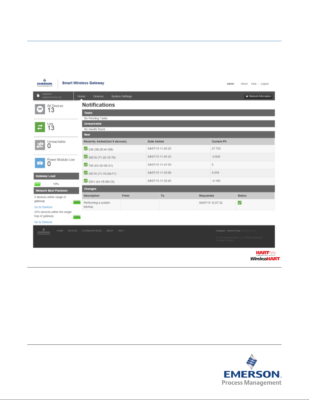
1.2 Home page
Manual Supplement
00809-1600-4420, Rev AA
Figure 1-1. Home
2
Smart Wireless Gateway Terminology Guide for Firmware Rev 4.5
Page 3

Manual Supplement
00809-1600-4420, Rev AA
Smart Wireless Gateway Terminology Guide for Firmware Rev 4.5
September 2015
Table 1-1. Home
Item Description
Devices Click to view a list of all devices participating in the network.
System Settings Click to view and edit all the accessible settings in the gateway.
Network Information Click to view network information and when adding a new device to the network.
About
Help Click to find additional help documentation.
Logout Allows user to sign out of the user interface
Gateway Status Icon Displays gateway name and indicates when gateway is in simplex or redundant mode
All Devices Click to view all devices participating in the gateway’s network.
Live Click to view all devices currently online (does not include unreachable devices).
Unreachable Click to view all devices that have dropped offline or are not publishing as configured.
Power Module Low Click to view all devices signaling that their power module is low (needs to be replaced).
Gateway Load Indicates percentage of available gateway bandwidth currently in use
Network Best Practices
Click to find detailed gateway information such as serial numbers, version number, system up
time, etc.
Provides snap shot of the most critical network best practices (for more information, see the
Systems Engineering Guide on www.emerson.com)
5 devices within range
of gateway
25% devices within the
singe hop of gateway
Indicates percentage based on number of devices directly communicating with the gateway
(once five or more devices are within range, percentage will remain at 100%)
Indicates percentage based on number of devices directly connected to the gateway (if at least
25% of network devices have gateway connection, this value will be 100%)
Ta sk s Provides information on recommended/required actions
New Newly added devices (includes last five devices added to the network)
Recently Added
(last 5 devices)
Last five devices added to the network
Date Added Date and time device was added
Current PV Last received primary process variable (PV) value
Changes Most recent changes to the gateway and network
Description Details of any changes made
From Previous value of any parameters involved in a change
To Current value of any parameters involved in a change
Requested Date and time action was performed
Status Change status (either successful or not)
Smart Wireless Gateway Terminology Guide for Firmware Rev 4.5
3
Page 4

Smart Wireless Gateway Terminology Guide for Firmware Rev 4.5
September 2015
1.3 About
Figure 1-2. About
Manual Supplement
00809-1600-4420, Rev AA
Table 1-2. About
Item Description
Gateway Final Assembly Number Serial number supplied during final device assembly
Gateway Serial Number Unique software serial number used by firmware to identify that particular gateway
Gateway Version
System Up Time Amount of time the system has been up and running
Software version currently installed on the gateway (to check for updated firmware,
see www.emerson.com)
4
Smart Wireless Gateway Terminology Guide for Firmware Rev 4.5
Page 5

Manual Supplement
00809-1600-4420, Rev AA
Smart Wireless Gateway Terminology Guide for Firmware Rev 4.5
1.4 Network Information
Figure 1-3. Network Information
Table 1-3. Network Information
September 2015
Item Description
Network ID
Common Join Key
Turn on Active Advertising
Network Settings Click to view full list of the network settings.
Unique ID used for this particular gateway network. Each field device must be configured with
this ID to join this gateway's wireless network. The gateway pushes this information to all
devices when changed if they are connected to the network.
Gateway's current common join key (password that allows devices to securely join wireless
network). Each device must be configured with this key to join this gateway's wireless network.
Toggles the method gateway uses to search for new network devices. Devices will join without
this feature however enabling this will make the process faster (automatically enabled if a
device drops offline).
Smart Wireless Gateway Terminology Guide for Firmware Rev 4.5
5
Page 6

Smart Wireless Gateway Terminology Guide for Firmware Rev 4.5
September 2015
1.5 Devices
Figure 1-4. Devices
Manual Supplement
00809-1600-4420, Rev AA
Table 1-4. Devices
Item Description
Device sorting and filtering tools
Device Icons Allows user to filter device by their current state (Live, Unreachable, Power Module, or All Devices)
First dropdown Allows user to select number of devices shown on the page
Second dropdown
Third dropdown Allows user to select sort display order based on device name
Fourth field Allows user to search list for a particular device name (or sub-string contained within the name)
Name Name of the device
PV
SV
TV
QV
Last Update Time stamp of last measurement received from the wireless field device
Allows user to filter device by their current state (Live, Unreachable, Power Module Low, or All
Devices)
Value of the HART® primary variable (1st variable), typically the primary function of the device
(e.g. temperature, pressure, level)
Value of the HART secondary variable (2nd variable), additional function of the device
(e.g. temperature, pressure, level)
Value of the HART tertiary variable (3rd variable), additional function of the device
(e.g. temperature, pressure, level)
Value of the HART quaternary variable (4th variable), additional function of the device
(e.g. temperature, pressure, level)
6
Smart Wireless Gateway Terminology Guide for Firmware Rev 4.5
Page 7
Manual Supplement
00809-1600-4420, Rev AA
Smart Wireless Gateway Terminology Guide for Firmware Rev 4.5
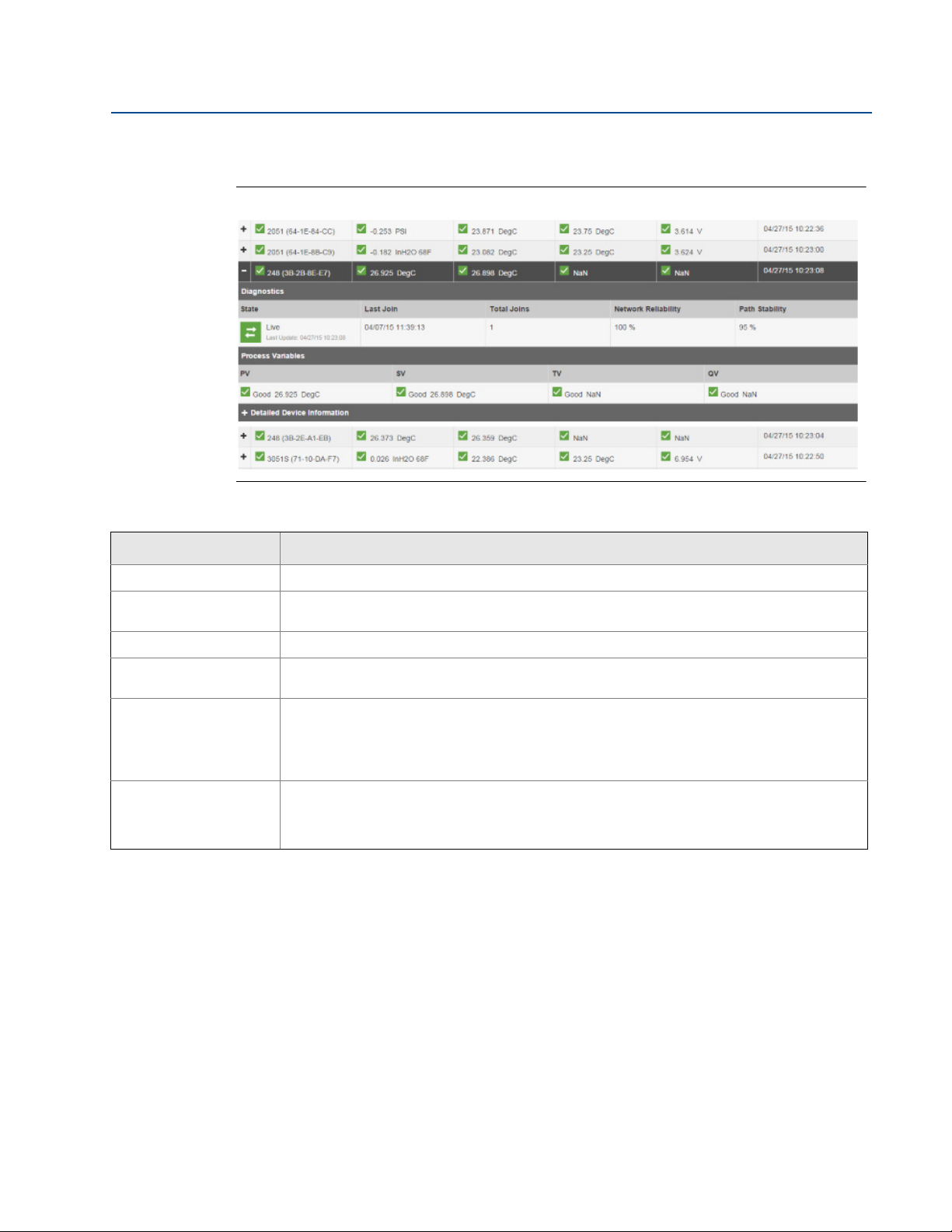
1.5.1 Devices > Open Devices bar
Figure 1-5. Open Devices
September 2015
Table 1-5. Open Devices
Item Description
Diagnostics Displays useful information for troubleshooting devices
State
Last Join Date and time field device made its last successful join
Total Joins
Network Reliability
Path Stability
Current device status (possibilities values include live, late, stale, joining, low voltage,
unreachable, or unknown)
Number of times field device has been successfully added to the network after being
unreachable
Percentage of packets transmitted by a device and received by the gateway (100.0% reliability
indicates every expected data packet was received). This value represents reliability of the
wireless network to deliver data and is rounded to the nearest tenth. This is a lifetime statistic
that is reset via a gateway restart; it is possible to have a small number of late/missed updates
over a long time and still have 100.0% reliability.
Percentage of transmitted packets successfully reaching their destination over a given path (two
neighboring devices) calculated over the most recent 15-minute period. Network reliability is
always higher than path stability due to automatic re-transmission using multiple paths and
different RF channels.
Smart Wireless Gateway Terminology Guide for Firmware Rev 4.5
7
Page 8
Smart Wireless Gateway Terminology Guide for Firmware Rev 4.5
September 2015
Manual Supplement
00809-1600-4420, Rev AA
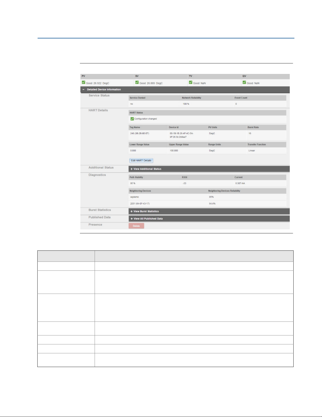
1.5.2 Devices > Open Devices bar > Detailed Device Information
Figure 1-6. Detailed Device Information
Table 1-6. Detailed Device Information
Item Description
Service Status Provides information regarding that device's bandwidth
Indicates whether the field device has been denied bandwidth because a) too many devices are
Service Denied
Network Reliability
Event Count
HART Details Displays device's HART information
HART Status Indicates overall field device HART status (if not green, troubleshooting may be required)
Tag Nam e
8
on the WirelessHART® network or b) the device has asked for an update rate not currently
supported by the wireless network (this can occur if there is a 'pinch-point' in the network that is
at its maximum load)
Percentage of packets transmitted by a device and received by the gateway (100.0% reliability
indicates every expected data packet was received). This value represents reliability of the
wireless network to deliver data and is rounded to the nearest tenth. This is a lifetime statistic
that is reset via a gateway restart; it is possible to have a small number of late/missed updates
over a long time and still have 100.0% reliability.
Indicates the number of times this action has occurred (number of times any enabled events are
triggered displays here)
32-character HART long tag (for HART 7 devices) or 32-character HART message (for HART 5
devices)
Smart Wireless Gateway Terminology Guide for Firmware Rev 4.5
Page 9

Manual Supplement
00809-1600-4420, Rev AA
Smart Wireless Gateway Terminology Guide for Firmware Rev 4.5
Table 1-6. Detailed Device Information
Item Description
Unique device identification number, all WirelessHART devices should begin with 00-1E-1B (next
Device ID
PV Units Units of measure of the primary variable (PV)
Burst Rate
four digits represent device type, the last six digits vary from device to device).
This name cannot be changed; it represents the unique device the same way a serial number
would. Keep track of this number if using the Access Control list.
Interval the field device transmits it’s measurement data to the gateway (set based on how often
the user wants the device to send data to the gateway). Some field devices burst multiple
messages and at different rates. Burst rates under one minute are reported in seconds white
rates one minute or greater are reported in hh:mm:ss. Also known as update rate.
September 2015
Lower Range Value
primary variable (when primary variable reaches the Lower Range Value, the percent of range
will be 0%)
User-configured upper range point used to calculate percent of range value based on current
User-configured lower range point used to calculate percent of range value based on current
Upper Range Value
primary variable (when primary variable reaches the Upper Range Value, the percent of range
will be 100%)
Range Units Engineering unit of measure associate with the lower and upper range points
Transfer Function Describes algorithm used to compute the percent of range for the primary variable
Edit HART Details Enable this to edit the features in the table (remember to save after editing)
View Additional Status Expand to view additional field device statuses
Diagnostics General information provided by the device and its neighbors
Percentage of transmitted packets successfully reaching their destination over a given path (two
Path Stability
neighboring devices) calculated over the most recent 15-minute period. Network reliability is
always higher than path stability due to automatic re-transmission using multiple paths and
different RF channels.
Received signal strength indication (RSSI) for the field device and neighbor (average calculated
RSSI
over the most recent 15-minute period). It represents how well that device is hearing other
devices or the gateway within a network during a receive. Ideally, this number is greater than -79
dBm (e.g. a -45 dBm device has a greater signal strength than -79 dBm).
Current Loop current controlled or measured by the field device
Other nearby field devices with connections to this device (also known as neighbors). This
Neighboring Devices
indicates the HART tag of other devices within range of that device or gateway and will populate
up to three of the strongest devices.
Neighboring Devices
Reliability
Path stability of the neighboring devices.
View Burst Statistics
View All Published Data
Delete
Smart Wireless Gateway Terminology Guide for Firmware Rev 4.5
Expand to view all burst statistics for the field device and status of communication between the
device and gateway
Expand to view all published parameters for the field device (each parameter can be mapped in
the protocols section)
Removes the device completely from the network and from all gateway host and user interfaces
(device must be offline for this function to work)
9
Page 10
Smart Wireless Gateway Terminology Guide for Firmware Rev 4.5
September 2015
Manual Supplement
00809-1600-4420, Rev AA
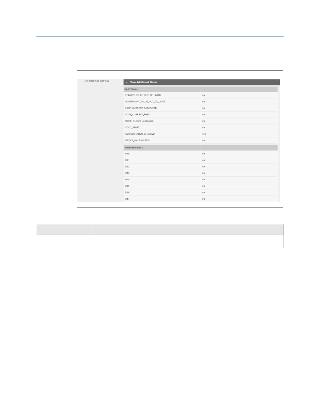
1.5.3 Devices > Open Devices bar > Detailed Device Information >
View Additional Status
Figure 1-7. View Additional Status
Table 1-7. View Additional Status
Item Description
Additional Status
Displays detailed status information published by the field device (reference the device
manufacturer's documentation for additional information)
10
Smart Wireless Gateway Terminology Guide for Firmware Rev 4.5
Page 11
Manual Supplement
00809-1600-4420, Rev AA
Smart Wireless Gateway Terminology Guide for Firmware Rev 4.5
September 2015
1.5.4 Devices > Open Devices bar > Detailed Device Information >
View Burst Statistics
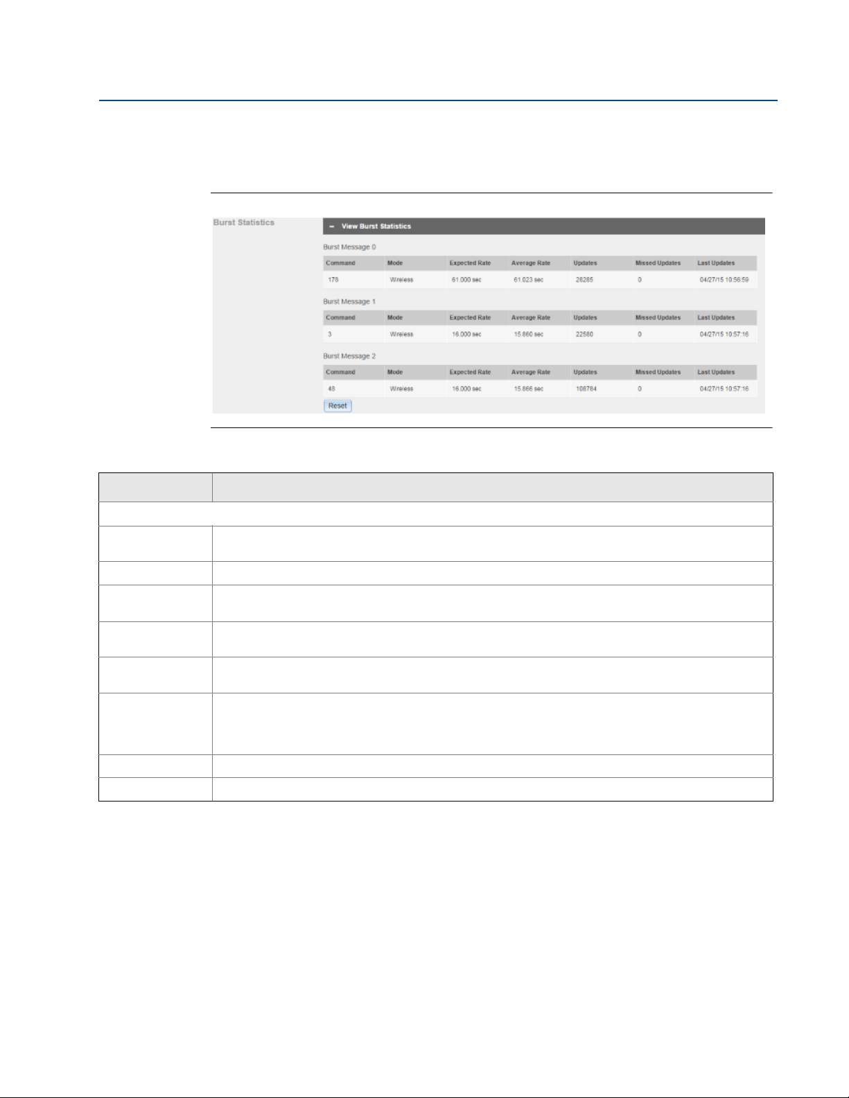
Figure 1-8. View Burst Statistics
Table 1-8. View Burst Statistics
Item Description
Burst Statistics
Command
Mode Device interface used to publish the command
Expected
Rate
Average Rate
Updates
Missed
Updates
Last Updates Time stamp of the last burst message received
Reset Clears all previous burst statistics shown, and resets all values in this section
HART command number published by the device (a field device may publish multiple commands at
different burst intervals)
Expected time interval between successive burst messages.
Average time interval between burst messages calculated for all messages received since the device
initially joined the network or since burst statistics were reset by the user
Number of updates received from the device since initially joining the network or since user reset the
burst statistics
Number of updates device has missed since initially joining the network or since user reset the burst
statistics. Missed updates can be caused by the device falling off line (e.g. during power module
replacement) or poor network reliability. Packets arriving late or out of sequence are also counted as
missed.
Smart Wireless Gateway Terminology Guide for Firmware Rev 4.5
11
Page 12
Smart Wireless Gateway Terminology Guide for Firmware Rev 4.5
September 2015
Manual Supplement
00809-1600-4420, Rev AA
1.5.5 Devices > Open Devices bar > Detailed Device Information >
View All Published Data
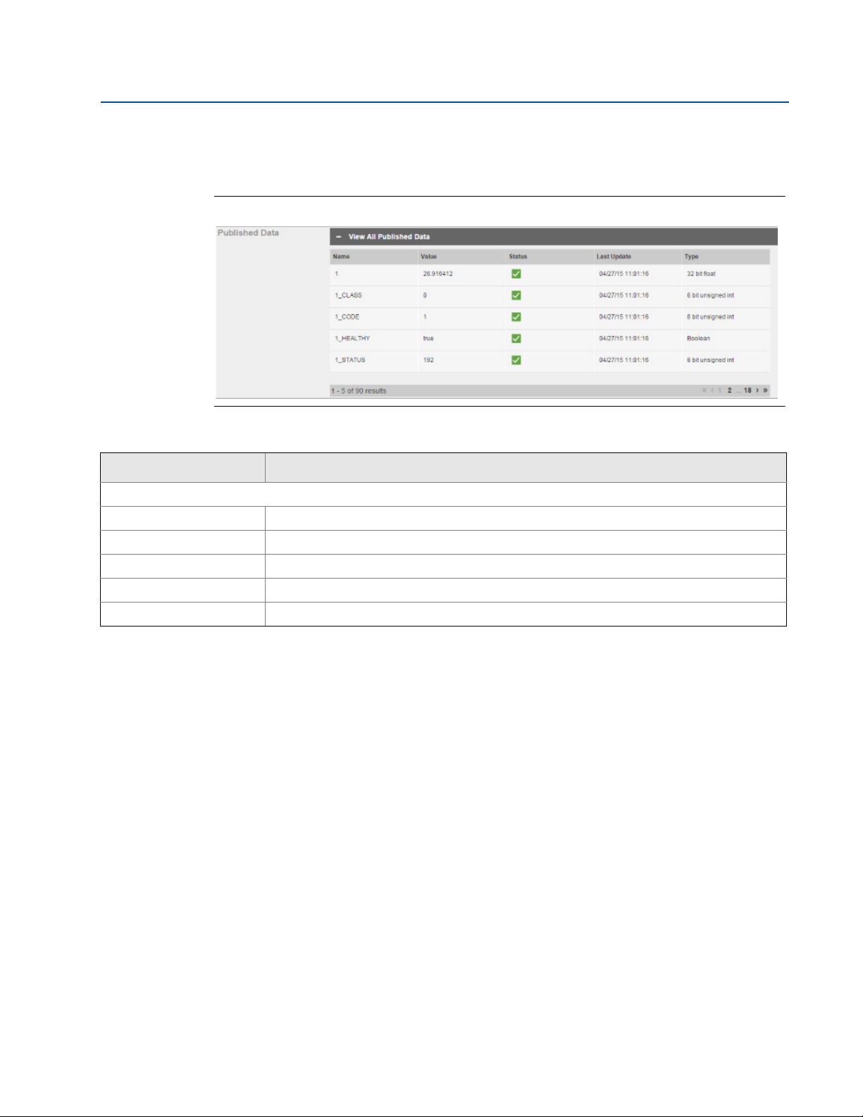
Figure 1-9. View All Published Data
Table 1-9. View All Published Data
Item Description
Published Data
Name Parameter name
Val ue Current parameter value
Status HART status indicator for this parameter
Last Update Time stamp of last parameter value received from the wireless field device
Typ e Data type of parameter
12
Smart Wireless Gateway Terminology Guide for Firmware Rev 4.5
Page 13
Manual Supplement
00809-1600-4420, Rev AA
Smart Wireless Gateway Terminology Guide for Firmware Rev 4.5
1.6 System Settings
1.6.1 System Settings > Gateway
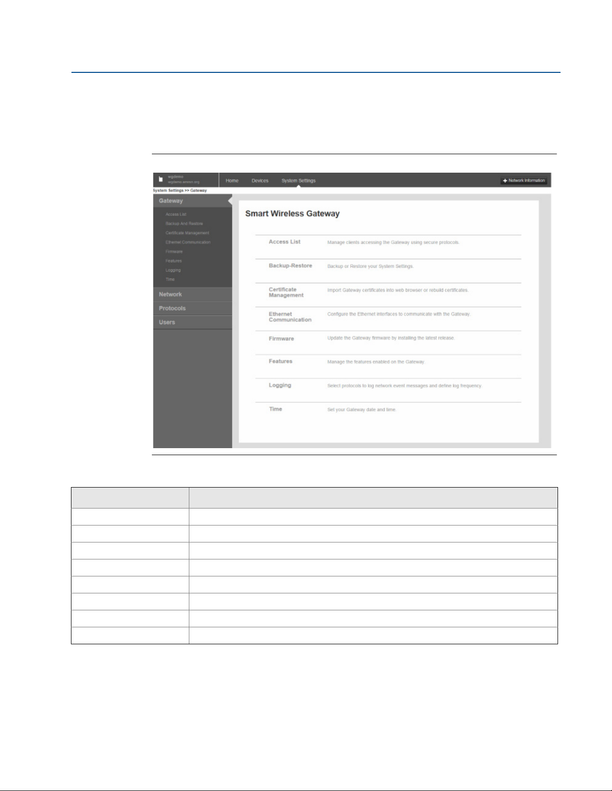
Figure 1-10. Gateway
September 2015
Table 1-10. Gateway
Item Description
Access List Click to manage clients accessing the gateway using secure protocols.
Backup and Restore Click to backup or restore system settings.
Certificate Management Click to import gateway certificates into web browser or rebuild certificates.
Ethernet Communication Click to configure Ethernet interfaces to communicate with the gateway.
Firmware Click to update the gateway firmware by installing the latest release.
Features Click to manage features enabled on the gateway.
Logging Click to select protocols for logging network event messages and define log frequency.
Time Click to set gateway date and time.
Smart Wireless Gateway Terminology Guide for Firmware Rev 4.5
13
Page 14
Smart Wireless Gateway Terminology Guide for Firmware Rev 4.5
September 2015
1.6.2 System Settings > Network
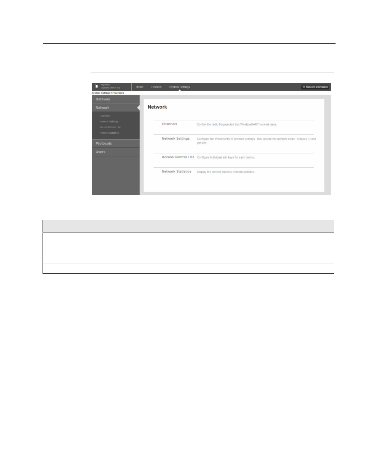
Figure 1-11. Network
Manual Supplement
00809-1600-4420, Rev AA
Table 1-11. Network
Item Description
Channels Click to control radio frequencies used by the WirelessHART network.
Network Settings Click to configure WirelessHART network settings (includes network name, network ID, and join key).
Access Control List Click to configure individual join keys for each device.
Network Statistics Click to display current wireless network statistics.
14
Smart Wireless Gateway Terminology Guide for Firmware Rev 4.5
Page 15

Manual Supplement
00809-1600-4420, Rev AA
Smart Wireless Gateway Terminology Guide for Firmware Rev 4.5
1.6.3 System Settings > Protocols
Figure 1-12. Protocols
September 2015
Table 1-12. Protocols
Item Description
Protocols and Ports Click to set up security protocols for the gateway using TCP and UDP ports.
HART Click to set up HART Wireless Gateway and HART devices.
Modbus
EtherNet/IP
OPC Click to set up OPC browse tree information.
®
™
Click to establish network communication for Modbus devices.
Click to set up EtherNet/IP member map and communication settings.
Smart Wireless Gateway Terminology Guide for Firmware Rev 4.5
15
Page 16

Smart Wireless Gateway Terminology Guide for Firmware Rev 4.5
September 2015
1.6.4 System Settings > Users
Figure 1-13. Users
Table 1-13. Users
Item Description
Manual Supplement
00809-1600-4420, Rev AA
User Accounts Click to assign names and passwords for users accessing the gateway.
User Options Click to manage how users are able to log into the system.
16
Smart Wireless Gateway Terminology Guide for Firmware Rev 4.5
Page 17

Manual Supplement
00809-1600-4420, Rev AA
Smart Wireless Gateway Terminology Guide for Firmware Rev 4.5
1.7 System Settings > Gateway pages
1.7.1 System Settings > Gateway > Access List
Figure 1-14. Access List
September 2015
Table 1-14. Access List
Item Description
Organization Client’s organization name
Common Name Client’s name (PC name)
Email Client’s email address
Expiration Date the client’s certificate is no longer valid
Smart Wireless Gateway Terminology Guide for Firmware Rev 4.5
17
Page 18

Smart Wireless Gateway Terminology Guide for Firmware Rev 4.5
September 2015
Manual Supplement
00809-1600-4420, Rev AA
1.7.2 System Settings > Gateway > Backup and Restore
Figure 1-15. Backup & Restore
Table 1-15. Backup & Restore
Item Description
Include diagnostic information
in system backup
Save Backup
Browse
Restore to Default Returns gateway to default factory configuration
Restart App Used to complete the backup process
When checked, saves gateway diagnostics log information with the system backup file
Collects gateway configuration data and creates a system backup file saved on the PC
client as a zip file (∗.zip). System backups contain user passwords and keys used for
encrypting communication; store downloaded system backups in a secure location.
Opens a navigation window to locate a system backup zip file (∗.zip) on the PC client and
then restores selected backup file to the gateway
18
Smart Wireless Gateway Terminology Guide for Firmware Rev 4.5
Page 19

Manual Supplement
00809-1600-4420, Rev AA
Smart Wireless Gateway Terminology Guide for Firmware Rev 4.5
September 2015
1.7.3 System Settings > Gateway > Certificate Management
Figure 1-16. Certificate Management
Table 1-16. Certificate Management
Item Description
Use self-signed certificate?
Import Gateway certificate
into web browser
Rebuild Gateway
certificates
Smart Wireless Gateway Terminology Guide for Firmware Rev 4.5
Select Yes to have digital certificate signed by same entity (wireless gateway) whose identity it
certifies (i.e. the gateway signs its own certificate).
Sends gateway security certificates to current web browser
Rebuilds security certificates for the gateway (may temporarily interrupt gateway
communications)
19
Page 20

Smart Wireless Gateway Terminology Guide for Firmware Rev 4.5
September 2015
Manual Supplement
00809-1600-4420, Rev AA
1.7.4 System Settings > Gateway > Ethernet Communication
Figure 1-17. Ethernet Communication
Table 1-17. Ethernet Communication
Item Description
Primary Interface [Port 1] Refers to Ethernet port 1
Specify an IP address
(recommended)
Obtain an IP address from
a DHCP server
Obtain Domain Name
from DHCP server
Interface Physical Address
Full Primary Host Name
Host Name Host name for the WirelessHART Gateway
Domain Name Name of the domain the WirelessHART Gateway will join
IP Address User-specified IP address for associated interface
20
Select this to insert a unique IP address matching local communication best practices
(consult IT personnel if needed when adding gateway to a specific LAN or router)
Select this to make associated interface obtain IP address from a DHCP server.
When checked, makes associated interface obtain a Domain Name from a DHCP server
Binary number in the form of logical high and low states on an address bus corresponding
to a particular cell of primary storage (i.e. main memory), or to a particular register in a
memory-mapped I/O (input/output) device
Unique name by which a computer is known on a network (used to identify in electronic
mall, Usenet news, or other forms of electronic information interchange)
Smart Wireless Gateway Terminology Guide for Firmware Rev 4.5
Page 21

Manual Supplement
00809-1600-4420, Rev AA
Table 1-17. Ethernet Communication
Item Description
Smart Wireless Gateway Terminology Guide for Firmware Rev 4.5
September 2015
NetMask
Gateway User-configurable network node that serves as an access point to another network
Secondary Interface [Port 2] Refers to Ethernet port 2
Enable/Disable Port When checked, turns port off to prevent tampering
User-configurable string of 0's and 1's that mask or screen out the network part of an IP
address so only the host part of the address remains
1.7.5 System Settings > Gateway > Firmware
Figure 1-18. Firmware
Table 1-18. Firmware
Item Description
Firmware Upgrade
Smart Wireless Gateway Terminology Guide for Firmware Rev 4.5
Procedure for installing new/improved firmware in the gateway. Firmware upgrade requires a
restart (shut down of wireless system); carefully follow recommended upgrade procedure
supplied with the firmware upgrade.
21
Page 22

Smart Wireless Gateway Terminology Guide for Firmware Rev 4.5
September 2015
1.7.6 System Settings > Gateway > Features
Figure 1-19. Features
Manual Supplement
00809-1600-4420, Rev AA
Table 1-19. Features
Item Description
Gateway Name Host name for the WirelessHART Gateway
Serial No
Features installed on the
Gateway
Unique software serial number used by the firmware to identify that particular installation (only
used if factory needs more information or firmware upgrades)
Protocols currently installed on the gateway
22
Smart Wireless Gateway Terminology Guide for Firmware Rev 4.5
Page 23

Manual Supplement
00809-1600-4420, Rev AA
Smart Wireless Gateway Terminology Guide for Firmware Rev 4.5
1.7.7 System Settings > Gateway > Logging
Figure 1-20. Logging
September 2015
Table 1-20. Logging
Item Description
Enable Remote logging When checked, enables remote system logging feature
Remote Server IP
Address
Remote server Port Protocol port for the remote Syslog server
Syslog Protocol
Syslog Transport
Require trusted server
certificate?
Log keep-alive message?
Keep-alive message
frequency (minutes)
View System Log Opens a window where you can view the most recent system log information and definitions
Smart Wireless Gateway Terminology Guide for Firmware Rev 4.5
IP address of the machine running the remote Syslog server
Selects format used for logged messages (newer format is IETF-Syslog and defined in RFC 5424,
legacy format is BSD and defined in RFC 3164)
Selects transport used for communication with remote Syslog server (choices are UDP, TCP, or
TLS [encrypted])
When using TLS encrypted communication, the remote Syslog server can use a trusted
certificate or a certificate unknown to the gateway. Select Yes for an added level of security and
exchange keys with the gateway using the security setup on remote Syslog server.
Select Yes to make the gateway send a ‘keep-alive’ message when no other log activity has
occurred. This provides another method for remote Syslog server to verify communication with
the gateway.
Frequency the ‘keep-alive’ message is sent
23
Page 24

Smart Wireless Gateway Terminology Guide for Firmware Rev 4.5
September 2015
1.7.8 System Settings > Gateway > Time
Figure 1-21. Time
Manual Supplement
00809-1600-4420, Rev AA
Table 1-21. Time
Item Description
You r PC ’s t ime Time used by the PC client
Gateway time Time currently used by the gateway
Difference Difference between current operating system time clock and gateway time clock
Method used to set time
Time server IP address of a known time server to which the gateway clock is synchronized
NTP server type Selects type of time server
NTP packet version Selects packet version of time server
Selects the way gateway synchronizes the time to a specific third party device including
separate NTP (network time protocol) or your PC time (NTP is the recommended method)
24
Smart Wireless Gateway Terminology Guide for Firmware Rev 4.5
Page 25

Manual Supplement
00809-1600-4420, Rev AA
Smart Wireless Gateway Terminology Guide for Firmware Rev 4.5
1.8 System Settings > Network pages
1.8.1 System Settings > Network > Channels
Figure 1-22. Channels
September 2015
Table 1-22. Channels
Item Description
Enable
Channel IEEE 802.15.4 channel number
Frequency (GHz) Frequency of the channel being used
Smart Wireless Gateway Terminology Guide for Firmware Rev 4.5
When checked, enables associated channel (used to determine which channels are used within
the gateway’s broadcast). This is not required for normal operation; only use if required in very
heavy RF situations.
25
Page 26

Smart Wireless Gateway Terminology Guide for Firmware Rev 4.5
September 2015
1.8.2 System Settings > Network > Network Settings
Figure 1-23. Network Settings
Manual Supplement
00809-1600-4420, Rev AA
Table 1-23. Network Settings
Item Description
Network name User-defined network name
Network ID
Join Key
Rotate network key?
Change network key
now?
Security mode
Active Advertising
26
Unique ID used for this particular gateway’s network (can be set so each device initially joins the
network along with the common join key). The gateway pushes this information to all devices
when changed if they are connected to the network.
Represents network being connected to, and the password required to access it (typically
defaulted in each gateway and will not be used when enabling the access control list)
Select Yes to make gateway generate a new random network key (encryption) on a periodic
basis (a period of time between rotations must be determined from 10-100 days; default is 90
days)
Select Yes to automatically generate a random key and push to existing network devices (occurs
when Save Changes is selected)
Selects whether the gateway uses a common join key or access control list to determine which
devices can join the WirelessHART network
Select Yes to make gateway actively search for new network devices. Devices will join without
this feature however enabling this makes process faster (automatically enabled if a device drops
offline).
Smart Wireless Gateway Terminology Guide for Firmware Rev 4.5
Page 27

Manual Supplement
00809-1600-4420, Rev AA
Smart Wireless Gateway Terminology Guide for Firmware Rev 4.5
1.8.3 System Settings > Network > Access Control List
Figure 1-24. Access Control List
September 2015
Table 1-24. Access Control List
Item Description
Unique device identification number, all WirelessHART devices should begin with
Device ID
Device Name Device's HART Tag
Generate New Join key When checked, generates new unique join key for the device
Online Indicates device is communicating on the WirelessHART network
Common Join Key Indicates whether device is using common join key
Default Join Key Indicates whether device is using the default join key
Check Generated Key for Selected Checks the Generate New Join Key box for all selected entries
New Join Key Recommended Selects all devices with a common join key or a default join key
00-1B-1E (next four digits represent device type, the last six digits vary from device to
device). This name cannot be changed; it represents the unique device the same way a
serial number would.
Smart Wireless Gateway Terminology Guide for Firmware Rev 4.5
27
Page 28

Smart Wireless Gateway Terminology Guide for Firmware Rev 4.5
September 2015
Manual Supplement
00809-1600-4420, Rev AA
1.8.4 System Settings > Network > Network Statistics
Figure 1-25. Network Statistics
Table 1-25. Network Statistics
Item Description
Name Name of the device HART tag
Percentage of packets transmitted by a device and received by the gateway (100.0% reliability
Network Reliability
Bandwidth Available
Joins
Join Time
28
indicates every expected data packet was received). This value represents reliability of the wireless
network to deliver data and is rounded to the nearest tenth. This is a lifetime statistic that is reset via
a gateway restart; it is possible to have a small number of late/missed updates over a long time and
still have 100.0% reliability.
Indicates whether field device has been denied bandwidth because the device has requested an
update rate exceeding available network capacity or has poor network topology.
If experiencing issues, too many devices at too fast of update rates may exist to be supported within
the network. Review network topology with respect to pinch points, update rates, and number of
devices. Ensure the network meets best practices. Tools such as AMS
Gateway Capacity Estimator can provide deeper insight into network topology issues and gateway
loading.
Number of times field device has joined the network since the last system reset (high value may
indicate some connectivity issue with that device). The number of joins increases at every power
module replacement or when the device is removed from the network and rejoins.
Time the device joined the network (may be helpful to diagnose connectivity issues when combined
with the number of joins)
®
Wireless SNAPON™ or the
Smart Wireless Gateway Terminology Guide for Firmware Rev 4.5
Page 29

Manual Supplement
00809-1600-4420, Rev AA
Table 1-25. Network Statistics
Item Description
Smart Wireless Gateway Terminology Guide for Firmware Rev 4.5
September 2015
Neighboring Device
RSSI
To
From
Path Stability
Other nearby field devices with connections to this device (provides the HART tag of other devices
within range of that device or gateway with active communication to that device)
Received signal strength indication (RSSI) for the field device and neighbor (average calculated over
the most recent 15-minute period). It represents how well that device is hearing other devices or the
gateway within a network during a receive. Ideally, this number is greater than -79 dBm (e.g. a -45
dBm device has a greater signal strength than -79 dBm).
RSSI to the neighbor device, defines the connection to the neighbor device (significant mismatch
between the “from” and “to” RSSI may require additional investigation)
RSSI from the neighbor device, defines the connection from the neighbor device (significant
mismatch between the “from” and “to” RSSI may require additional investigation)
Percentage of transmitted packets successfully reaching their destination over a given path (two
neighboring devices) calculated over the most recent 15-minute period. Network reliability is always
higher than path stability due to automatic re-transmission using multiple paths and different RF
channels.
Smart Wireless Gateway Terminology Guide for Firmware Rev 4.5
29
Page 30

Smart Wireless Gateway Terminology Guide for Firmware Rev 4.5
September 2015
Manual Supplement
00809-1600-4420, Rev AA
1.9 System Settings > Protocols pages
1.9.1 System Settings > Protocols > Protocols and Ports
Figure 1-26. Protocols and Ports
Table 1-26. Protocols and Ports
Item Description
Enabled
Protocol Type of Ethernet communication protocol
Port Type Either TCP or UDP port used by the associated communication protocol
Port Port number for the associated communication protocol and port type
Port Upper Range (UDP)
AMS Secure
DHCP
EtherNet/IP
30
When checked, enables associated communication protocol and opens specified TCP/UDP
port
Range of ports used for this protocol (usually a fixed number of difference between UDP and
regular)
SSL-enabled Ethernet communication protocol used to talk to asset management hosts (also
requires HTTPS)
Network protocol that enables a server to automatically assign an IP address to a computer
from a defined range of numbers (i.e., a scope) configured for a given network
Member of a family of networks that implements the Common Industrial Protocol (CIP™) at
its upper layers. CIP encompasses a comprehensive suite of messages and services for a
variety of manufacturing automation applications, including control, safety,
synchronization, motion, configuration, and information.
Smart Wireless Gateway Terminology Guide for Firmware Rev 4.5
Page 31

Manual Supplement
00809-1600-4420, Rev AA
Table 1-26. Protocols and Ports
Item Description
Smart Wireless Gateway Terminology Guide for Firmware Rev 4.5
September 2015
HART-IP
HART-IP Secure
HTTP Ethernet communication protocol used for the gateway’s web based user interface
HTTPS
Modbus TCP Ethernet communication protocol used to talk to Modbus TCP-enabled hosts
Modbus TCP Secure
NTP Communication port used to talk to a Network Time Protocol (NTP) server
OPC Comm
OPC Comm Secure SSL-enabled Ethernet communication protocol used to communicate to OPC enabled hosts
Additional connection option that facilitates host level systems and assets and integrates
measurement and device diagnostics information from HART-enabled field devices using the
existing plant networking infrastructure
SSL-enabled Ethernet communication protocol used to talk to HART enabled hosts (requires
HTTPS)
SSL-enabled Ethernet communication protocol used for the gateway’s web-based user
interface
SSL-enabled Ethernet communication protocol used to talk to Modbus TCP-enabled hosts
(requires HTTPS)
Interoperability standard for secure and reliable exchange of data in the industrial
automation space and in other industries
1.9.2 System Settings > Protocols > HART
Figure 1-27. HART
Table 1-27. HART
Item Description
Gateway Name Host name for the WirelessHART Gateway
Use ethernet protocol
host name for Gateway
name
Allow Gateway to be
seen as field device
Smart Wireless Gateway Terminology Guide for Firmware Rev 4.5
When checked, uses the host name field under the Ethernet page to replace the gateway name
(one-time action). Further host name changes will not be reflected on this page unless the box is
rechecked.
Select Yes to allow the gateway to be seen as a field device on device specific pages
31
Page 32

Smart Wireless Gateway Terminology Guide for Firmware Rev 4.5
September 2015
Figure 1-28. HART Statistics
Table 1-28. HART Statistics
Item Description
Description Explains mapped parameter
XML Stats
HART communications over XML protocol (associated with AMS Wireless Configurator and AMS
communication protocols)
Manual Supplement
00809-1600-4420, Rev AA
UDP Stats
TCP Stats
Message Received
Message Returned Number of messages gateway returned to a client application (can be any HART-enabled host)
Message Broadcast Number of periodic (scheduled) messages gateway received from a client application
Requests Forwarded
Requests Returned Number of messages gateway received from field devices in response to forwarded requests
Message Connections Number of connections included on the HART IP
Online Connections Number of connections active
Reset Counts Resets all HART statistics
HART communications over UDP protocol (associated with the HART UDP Port communication
protocol)
HART communications over TCP protocol (associated with the HART TCP Port and HART TCP
Secure communication protocol)
Number of messages gateway received from a client application (can be any HART-enabled
host)
Number of messages gateway has forwarded to field devices (not all messages received are
forward because some information is cached in the gateway)
32
Smart Wireless Gateway Terminology Guide for Firmware Rev 4.5
Page 33

Manual Supplement
00809-1600-4420, Rev AA
Smart Wireless Gateway Terminology Guide for Firmware Rev 4.5
1.9.3 System Settings > Protocols > Modbus page
1.9.3.1 System Settings > Protocols > Modbus > Mappings
Figure 1-29. Mappings
September 2015
Table 1-29. Mappings
Item Description
Add New Entry Creates a new entry in the table
Show/Hide System
Registers
Import Mappings Opens a window to browse and locate a Modbus mapping backup file (CSV file) on the PC client
Export Mappings
Register Memory location used to reference point data via Modbus protocol (Modbus holding register)
Point Name Assigned data point in the format HARTtag.parameter
State
Invert When checked, switches the 0 or 1 response for discrete state values for associated point name
Shows/hides predefined system registers
49001 = current year, 49002 = current month, 49003 = current day, 49004 = current hour,
49005 = current minute, 49006 = current second, 49007 = messages received...
Collects gateway Modbus mapping data and creates a backup file (saved on PC client as a CSV
∗
.csv])
file [
For Booleans, indicates which value will be reported as a 1. For integers, identifies a particular
bit to be reported as 1 (reserved for registers less than 20000)
Smart Wireless Gateway Terminology Guide for Firmware Rev 4.5
33
Page 34

Smart Wireless Gateway Terminology Guide for Firmware Rev 4.5
September 2015
Manual Supplement
00809-1600-4420, Rev AA
1.9.3.2 System Settings > Protocols > Modbus > Communication
Settings
Figure 1-30. Communication Settings
Table 1-30. Communication Settings
Item Description
Single Modbus Address Select to use a single Modbus RTU slave address
Multiple Modbus
Addresses
Baud Rate Communication speed for Modbus RTU
Response Delay Time (ms) After receiving a request, gateway will wait this long before it sends a response
Unmapped Register Read
Response?
Unmapped Register Write
Response?
Parity Selects whether parity is used for Modbus RTU messages and whether it is even or odd
Stop Bits Selects number of stop bits for Modbus RTU messages
Select to use multiple Modbus RTU slave addresses (configured per point in the Modbus
mapping page)
Selects the response gateway sends if no data is mapped to the register during a read request
(gateway can either return zero for the requested register or illegal data address exception)
Selects the response gateway sends if no data is mapped to the register during a write request
(gateway can either return zero for the requested register or illegal data address exception)
34
Smart Wireless Gateway Terminology Guide for Firmware Rev 4.5
Page 35

Manual Supplement
00809-1600-4420, Rev AA
Smart Wireless Gateway Terminology Guide for Firmware Rev 4.5
1.9.3.3 System Settings > Protocols > Modbus > Format Settings
Figure 1-31. Communication Settings
Table 1-31. Communication Settings
September 2015
Item Description
Floating point
representation
Value reported for error
(floating point)
NaN Reported if value’s associated status indicates a critical failure
Infinity Reported if value’s associated status indicates a critical failure
-Infinity Reported if value’s associated status indicates a critical failure
Other User-defined value reported if value's associated status indicates a critical failure
Value reported for error
(rounded and native integer)
Byte Swap When checked, reverses significant register used in a floating point representation
Selects format in which Modbus data is given
Selects value reported if the value’s associated status indicates a critical failure (only used if
gateway is using float representation)
Only used when round or scale is selected under floating point representation
Smart Wireless Gateway Terminology Guide for Firmware Rev 4.5
35
Page 36

Smart Wireless Gateway Terminology Guide for Firmware Rev 4.5
September 2015
Manual Supplement
00809-1600-4420, Rev AA
1.9.3.4 System Settings > Protocols > Modbus > Modbus Statistics
Figure 1-32. Modbus Statistics
Table 1-32. Modbus Statistics
item Description
Name Statistic name being used
Serial These statistics are only available over serial communications or Modbus 485.
TCP These statistics are only available over Ethernet TCP Modbus connections.
CRC errors
Messages received Number of messages received from Modbus master device
Exception responses This number increments if any exception is returned.
Connections accepted
Active connections Number of Modbus connections currently active on the gateway
Messages transmitted Number of response messages transmitted from the gateway
Reset Counts Resets all table values
Number of cyclic redundancy check errors (generally indicate noise in transmission or problems
with data integrity)
Number of total connections from Modbus TCP masters accepted over time (not the current
number of connections)
36
Smart Wireless Gateway Terminology Guide for Firmware Rev 4.5
Page 37

Manual Supplement
00809-1600-4420, Rev AA
Smart Wireless Gateway Terminology Guide for Firmware Rev 4.5
September 2015
1.9.4 System Settings > Protocols > EtherNet/IP page
1.9.4.1 System Settings > Protocols > EtherNet/IP > Member Map
Figure 1-33. EtherNet/IP Member Map
Table 1-33. EtherNet/IP Member Map
Item Description
Show/Hide System
Members
Add All PV Inserts new table entry for the primary value of every wireless field device
Import Mappings
Export Mappings
Input Instance (DEC) EtherNet/IP Input Static Assembly Instance – 496 bytes
Output Instance (DEC) EtherNet/IP Output Static Assembly Instance – 496 bytes
Member EtherNet/IP Instance Member in which data will get produced or consumed
Point Name Assigned data point in the format HARTtag.paramter
Toggles visibility of system members or data available (use to see what information is available
within the gateway by default)
Imports existing mapping from a csv file created through Excel® or obtained from another
gateway’s parameters
Exports current device parameters mapped for EtherNet/IP to be used offline or for another
gateway
Smart Wireless Gateway Terminology Guide for Firmware Rev 4.5
37
Page 38

Smart Wireless Gateway Terminology Guide for Firmware Rev 4.5
September 2015
Manual Supplement
00809-1600-4420, Rev AA
1.9.4.2 System Settings > Protocols > EtherNet/IP > Communication
Figure 1-34. EtherNet/IP Communication
Table 1-34. EtherNet/IP Communication
Item Description
Assembly Object Type Static assembly object type is the only type available with an EtherNet/IP application
Ethernet/IP TCP Port TCP Port used to access EtherNet/IP TCP data directly from gateway
Ethernet/IP UDP Port UDP Port used to access EtherNet/IP UDP data directly from gateway
Incorporate values
associated status as
error?
Value reported for error
(floating point)
NaN Reported if value’s associated status indicates a critical failure
Infinity Reported if value’s associated status indicates a critical failure
-Infinity Reported if value’s associated status indicates a critical failure
Other User-defined value reported if the value’s associated status indicates a critical failure
Value reported for error
(native integer)
Select Yes to report a critical failure or communication loss through the EtherNet/IP member if
HART variable status indicates a critical failure
Selects value reported if value’s associated status indicates critical failure (only used if gateway
is using float representation)
User-defined value reported if the value’s associated status indicates a critical failure (only used
if the gateway is using integer representation)
38
Smart Wireless Gateway Terminology Guide for Firmware Rev 4.5
Page 39

Manual Supplement
00809-1600-4420, Rev AA
Smart Wireless Gateway Terminology Guide for Firmware Rev 4.5
1.9.4.3 System Settings > Protocols > EtherNet/IP > Statistics
Figure 1-35. EtherNet/IP Statistics
September 2015
Table 1-35. EtherNet/IP Statistics
Item Description
CIP Messaging Statistics Used for troubleshooting networks
Description Description of the parameter being mapped to the host system
Val ue Value of the mapped parameter
Messages Received Statistics related to number of messages received
Messages Sent Statistics related to number of messages sent
UCMM Received
UCMM Sent UCMM statistics related to number of messages sent
UCMM Error Response UCMM statistics related to number of error responses
I/O Messaging Statistics Used for troubleshooting networks
I/O Packets Received Input/output packets received
I/O Packets Sent Input/output packets sent
I/O Packets Failed To Send Input/output packets that are going to send
I/O Packets Received Error Input/output packets received error
Active connections
Current I/O Message Connections Number of input/output packets that received connections
Unconnec ted Message Manager (U CMM) s tatis tics related to number of messa ges
received
Number of EtherNet/IP connections available (used to monitor number of active
connections to the EtherNet/IP module)
Current CIP Message Connections Number of CIP Message Connections currently connected to the device
Reset Counts Resets all table values
Smart Wireless Gateway Terminology Guide for Firmware Rev 4.5
39
Page 40

Smart Wireless Gateway Terminology Guide for Firmware Rev 4.5
September 2015
1.9.5 System Settings > Protocols > OPC
Figure 1-36. OPC Mappings
Manual Supplement
00809-1600-4420, Rev AA
Table 1-36. OPC Mappings
Item Description
Add New Entry Creates new entry in the table
Add All PV Creates new entry for the primary value of every wireless field device
Import Mappings Opens a window to browse and locate a Modbus mapping backup file (CSV file) on the PC client
Export Mappings
Point Name Assigned data point in the format HARTtag.parameter
String Value
Collects gateway Modbus mapping data and creates a backup file (saved on the PC client as a
CSV file [*.csv])
When checked, point data is represented in a string of characters rather than the default 32-bit
floating point
40
Smart Wireless Gateway Terminology Guide for Firmware Rev 4.5
Page 41

Manual Supplement
00809-1600-4420, Rev AA
Smart Wireless Gateway Terminology Guide for Firmware Rev 4.5
1.10 System Settings > Users pages
1.10.1 System Settings > Users > User Accounts
Figure 1-37. User Accounts
September 2015
Table 1-37. User Accounts
Item Description
Name Name of the user account
Func tion Access privileges for the user, administrator, maintenance, operations, or executive
Edit Edits corresponding field
These are the privileges that a maint user type has:
• Configure HART device settings
maint
oper Read-only access with the ability to delete inactive devices
admin Includes all maintenance privileges for administrators
exec Read-only access
• Configure Modbus communications
• Configure Modbus register mapping
• Configure OPC browse tree
• Configure Active Advertising
Smart Wireless Gateway Terminology Guide for Firmware Rev 4.5
41
Page 42

Smart Wireless Gateway Terminology Guide for Firmware Rev 4.5
September 2015
1.10.2 System Settings > Users > Users Options
Figure 1-38. Users Options
Table 1-38. Users Options
Item Description
Manual Supplement
00809-1600-4420, Rev AA
Password Strength
None Select to use no requirements
Minimal Select to set minimum requirements based on scaling of options possible
Normal Select to set normal password protection enabled based on scaling of options possible
Strong Select to set strong password protection based on the current options available
Custom Select to set input custom length requirements
Show Details Shows information to edit
Login page message Message displayed at user login page
Selects level or rules used for user password strength (i.e. none, minimal, normal, strong, or
custom) to enhance password strength requirements (recommended)
42
Smart Wireless Gateway Terminology Guide for Firmware Rev 4.5
Page 43

Manual Supplement
00809-1600-4420, Rev AA
Smart Wireless Gateway Terminology Guide for Firmware Rev 4.5
1.11 Redundancy option
1.11.1 System Settings > Gateway
Figure 1-39. Gateway
September 2015
Table 1-39. Gateway
Item Description
Redundancy Status Establishes and checks status of redundant gateway pair
Redundancy Selects a backup gateway to establish a redundant system
Smart Wireless Gateway Terminology Guide for Firmware Rev 4.5
43
Page 44

Smart Wireless Gateway Terminology Guide for Firmware Rev 4.5
September 2015
1.11.1.1 System Settings > Gateway > Redundancy Status
Figure 1-40. Redundancy Status
Table 1-40. Redundancy Status
Manual Supplement
00809-1600-4420, Rev AA
Item Description
Switchover
Toggles between primary and secondary gateway (commonly used to switch out gateways
without loss of network)
1.11.1.2 System Settings > Gateway > Redundancy
Figure 1-41. Redundancy System Settings
Table 1-41. Redundancy System Settings
Item Description
Redundant Mode Places gateway in redundant mode
Standalone Select to take gateway out of redundant mode (operates on its own)
Redundant Select to place gateway in redundant mode
44
Smart Wireless Gateway Terminology Guide for Firmware Rev 4.5
Page 45

Manual Supplement
00809-1600-4420, Rev AA
Smart Wireless Gateway Terminology Guide for Firmware Rev 4.5
September 2015
Smart Wireless Gateway Terminology Guide for Firmware Rev 4.5
45
Page 46

Global Headquarters
Emerson Process Management
6021 Innovation Blvd.
Shakopee, MN 55379, USA
+1 800 999 9307 or +1 952 906 8888
+1 952 949 7001
RFQ.RMD-RCC@EmersonProcess.com
North America Regional Office
Emerson Process Management
8200 Market Blvd.
Chanhassen, MN 55317, USA
+1 800 999 9307 or +1 952 906 8888
+1 952 949 7001
RMT-NA.RCCRFQ@Emerson.com
Latin America Regional Office
Emerson Process Management
1300 Concord Terrace, Suite 400
Sunrise, Florida, 33323, USA
+1 954 846 5030
+1 954 846 5121
RFQ.RMD-RCC@EmersonProcess.com
Manual Supplement
00809-1600-4420, Rev AA
September 2015
Europe Regional Office
Emerson Process Management Europe GmbH
Neuhofstrasse 19a P.O. Box 1046
CH 6340 Baar
Switzerland
+41 (0) 41 768 6111
+41 (0) 41 768 6300
RFQ.RMD-RCC@EmersonProcess.com
Asia Pacific Regional Office
Emerson Process Management Asia Pacific Pte Ltd
1 Pandan Crescent
Singapore 128461
+65 6777 8211
+65 6777 0947
Enquiries@AP.EmersonProcess.com
Middle East and Africa Regional Office
Emerson Process Management
Emerson FZE P.O. Box 17033,
Jebel Ali Free Zone - South 2
Dubai, United Arab Emirates
+971 4 8118100
+971 4 8865465
RFQ.RMTMEA@Emerson.com
Standard Terms and Conditions of Sale can be found at:
www.rosemount.com\terms_of_sale.
The Emerson logo is a trademark and service mark of Emerson Electric Co.
Rosemount and Rosemount logotype are registered trademarks of Rosemount Inc.
AMS is a registered trademark of Emerson Electric Co.
SNAPON is a trademark of Emerson Electrical Co.
HART and WirelessHART are registered trademarks of the FieldComm Group.
Modbus is a registered trademark of Modicon, Inc.
EtherNet/IP is a trademark of ControlNet International under license by ODVA.
Excel is a registered trademark of Microsoft Corporation in the United States and
other countries.
All other marks are the propert y of their respective owners.
© 2015 Rosemount Inc. All rights reserved.
Loading...