

Quick Start Guide
D-7010-0061, Rev C
January 2018
Rosemount CT5400 Continuous Gas Analyzer


Safety Information
All authorized users, including installation, operation, and maintenance personnel, must observe the following safety precautions
and warnings.
DANGER!
ELECTRIC SHOCK
The analyzer operates using mains voltage that is dangerous to life. Make sure that the power ON/OFF switch at the rear of the panel
is set to OFF and tagged off before removing the top cover.
The analyzer must be earthed.
Death or personal injury may result if this is not observed.
DANGER!
FAILURE TO LOCK-OUT GAS HANDLING SYSTEM MAY CAUSE DEATH.
Always lock out the gas handling system when shutting down the analyzer. Unauthorized operation of the gas handling system
when maintenance is being performed on the analyzer or its associated pipes/hoses may result in highly flammable gas being
released, causing fire or explosion.
DANGER!
FAILURE TO VENT SAMPLE GAS MAY CAUSE DEATH.
The sample gas in the system must be vented to prevent fire or explosion during maintenance and to prevent damage to the
analyzer during startup.
The sample gas in the pipes leading to the analyzer must be purged to prevent hazards to personnel during maintenance. Purging
the sample gas must be done in accordance with the safe working procedures for the site.
Allow the analyzer and system for returning the sample gas to run for five minutes to allow any sample gas in the system to be
returned to the exhaust.
WARNING!
ELECTRICAL SHOCK HAZARD
Do not operate without covers secure.
Do not open while energized.
Installation requires access to live parts which can cause death or serious injury.
For safety and proper performance, this instrument must be connected to a properly grounded three-wire source of power.

WARNING!
OPTICAL RADIATION EXPOSURE HAZARD
The analyzer contains lasers. Opening the analyzer and attempting to perform adjustments or procedures other than those specified
in this manual may result in hazardous optical radiation exposure.
All lasers used within the analyzer are Class 1. The emitted laser light is invisible (mid-infrared) and the combined laser powers are
sufficiently low at the first accessible aperture that the unprotected eye will not be damaged. This class is eye safe under all
operating conditions.
It is, however, possible to cause damage to the eye through not following correct procedures. Do not look at the laser with any kind
of magnifier or optical measuring device.
The use of control or adjustments or performance of procedures other than those specified herein may result in hazardous radiation
exposure.
WARNING!
HAZARDOUS SUBSTANCES
The analyzer may contain hazardous substances. Always handle the analyzer assemblies and components with extreme caution.
Gas handling components within the analyzer will contain particulate matter residue from the sample gases. Over the life of the
analyzer, the concentration of particulate matter will become enriched within the gas handling components. When performing
repairs and maintenance on the analyzer:
• Handle used gas handling components with extreme caution.
• Avoid direct skin contact with used gas handling components.
• Do not smoke, drink, or eat in the work area.
• Wear goggles or eye shields.
• Wear a suitable face mask to protect against inhalation of particulate matter.
• Do not wet fingers, eyes, or any exposed skin.
• Pack used gas handling components for disposal in sealed packaging and label them Contaminated.
Dispose of contaminated items as hazardous material according to the applicable local, national, or international health and safety
regulations and pollution regulations.
WARNING!
EXPLOSION HAZARD
Always lock-out tag-out the gas handling system when shutting down the analyzer. Unauthorized operation of the gas handling
system when maintenance is being performed on the analyzer or its associated pipes/hoses may result in highly flammable gas being
released, causing fire or explosion.
WARNING!
HEAVY ITEM
Handle the analyzer with caution during unpacking, installing, maintaining, and transporting to prevent crushing of hands, feet, or
other body parts.
The analyzer weighs 31 kg (68 lb). Always use suitable lifting/moving equipment when moving the analyzer. Wear suitable
protective gloves and protective footwear.
Failure to properly handle the analyzer may cause injury to personnel.
WARNING!
HAZARDOUS GAS
The product stream that the analyzer is examining may be hazardous even at low concentrations. Therefore, take special care to
ensure that the sample gas return port either returns the sample gas to the product stream or discharges the sample gas to a
location that will not cause a hazard.
WARNING!
HIGH PRESSURE GAS AND AIR
The calibration gas supply and compressed air supply operate at a pressure that can cause injury, e.g., damage to eyes and skin
punctures from debris blown by the high pressure gas or compressed air.
Always lock out or tag off the calibration gas supply and compressed air supply when shutting down the .
WARNING!
EXPLOSION HAZARD
The sample gas in the system must be vented to prevent fire or explosion during maintenance and to prevent damage to the
analyzer during startup.
The sample gas in the pipes leading to the analyzer must be purged to prevent hazards to personnel during maintenance. Purging
the sample gas must be done in accordance with the safe working procedures for the site.
Allow the analyzer and system for returning the sample gas to run for five minutes to allow any sample gas in the system to be
returned to the exhaust.
WARNING!
EXPLOSION
Danger of explosion if battery is incorrectly replaced. Replace only with the same or equivalent type.
CAUTION!
EQUIPMENT DAMAGE
Always follow the startup procedure. Damage to the may result from a failure to follow this procedure.
Failure to perform pre-system startup checks may cause damage to equipment.
CAUTION!
EQUIPMENT DAMAGE
Always follow the shutdown procedure. Damage to the analyzer may result from a failure to follow this procedure.
CAUTION!
EMC
This is a Class A product. In a domestic environment, this product may cause radio interference, in which case you may be required to
take adequate measures.
CAUTION!
EQUIPMENT DAMAGE
Ensure that the local power voltage where the unit is to be installed corresponds to the unit’s nominal voltage as given on the name
plate label.

CAUTION!
EQUIPMENT DAMAGE
Do not power up or try to operate the analyzer unless it is physically secure and all electrical and pneumatic connections to the
analyzer are in place.
Before commencing the start-up process, it is important to ensure that electrical power, sample gas handling facilities, and any
calibration gases that are required are available to the analyzer.

Contents
Contents
Chapter 1 Plan ..................................................................................................................................1
1.1 Unpacking the analyzer .................................................................................................................. 1
1.2 Rack mounting the analyzer ........................................................................................................... 2
1.2.1 Tools required ................................................................................................................. 3
1.3 Detailed system specifications ....................................................................................................... 4
Chapter 2 Install ...............................................................................................................................9
2.1 System overview ............................................................................................................................ 9
2.2 Gas inputs and outputs ................................................................................................................ 10
2.3 Connecting the electrical/electronic inputs and outputs .............................................................. 12
Chapter 3 Navigating the CT5400 Controls ..................................................................................... 15
3.1 Front panel controls and indicators .............................................................................................. 15
3.2 Rear panel controls .......................................................................................................................16
3.3 Display controller ......................................................................................................................... 17
3.4 Gas Sensor Main screen ................................................................................................................18
3.5 Pressure and Temperature screen ................................................................................................ 19
3.6 Help system ................................................................................................................................. 19
3.7 Main menu ...................................................................................................................................20
3.8 BACK button ................................................................................................................................ 21
Chapter 4 Startup procedure ..........................................................................................................23
4.1 Introduction .................................................................................................................................23
4.2 Preparation for use .......................................................................................................................23
4.3 Startup procedure ........................................................................................................................24
i

Contents
ii

1 Plan
1.1 Unpacking the analyzer
This procedure may require a minimum of two people to safely remove the equipment
from the shipping container.
WARNING!
HEAVY ITEM
Handle the analyzer with caution during unpacking, installing, maintaining, and transporting
to prevent crushing of hands, feet, or other body parts.
The analyzer weighs 31 kg (68 lb). Emerson™ recommends that the analyzer is only moved and
lifted by a minimum of two people. Wear suitable protective gloves and protective footwear.
Failure to properly handle the analyzer may cause injury to personnel.
Plan
WARNING!
TRANSPORTATION HAZARD
Use safety-approved lifting equipment. You must ensure safe lifting procedures for the weight
and mass of the equipment are followed.
Failure to use proper lifting procedures may cause injury to personnel or damage the analyzer.
Procedure
1. Visually inspect the exterior of the analyzer for signs of damage, corrosion, gas
leaks, or signs of previously overheating.
2. Report anything found to the maintenance organization.
3. safety approved and tested lifting equipment to remove the analyzer from the
shipping container.
4. Place the analyzer on a solid, level surface and prepare to mount the analyzer.
1
Plan
1.2 Rack mounting the analyzer
This procedure may require two people to safely move and rack mount the Rosemount
CT5400.
WARNING!
HEAVY ITEM
Handle the analyzer with caution during unpacking, installing, maintaining, and transporting
to prevent crushing of hands, feet, or other body parts.
The analyzer weighs 31 kg (68 lb). Emerson™ recommends that the analyzer is only moved and
lifted by a minimum of two people. Wear suitable protective gloves and protective footwear.
Failure to properly handle the analyzer may cause injury to personnel.
Note
You must supply the rack.
Procedure
1. One person aligns the analyzer's telescoping slide rails on the unit as the other
person carefully guides the analyzer into the rack using the front panel and rear
handles (see Figure 1-1).
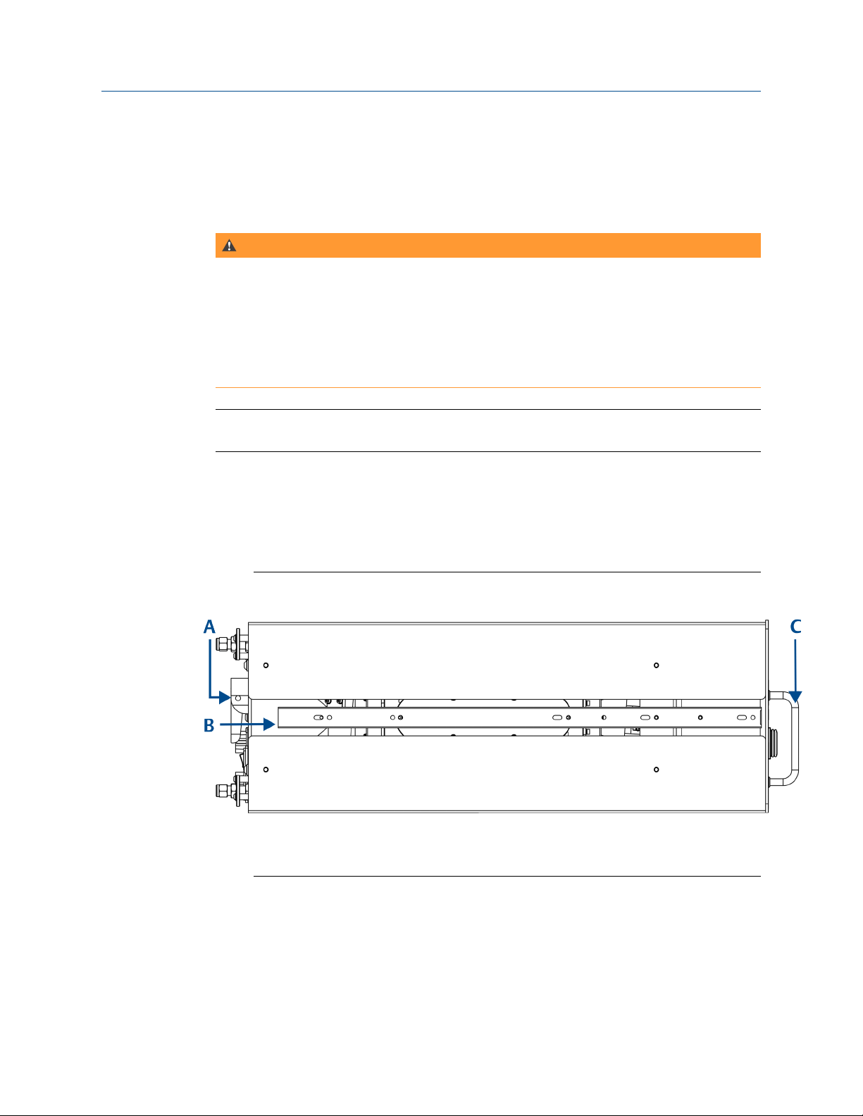
Left Side View - Lifting Handles and Telescopic Slide RailsFigure 1-1:
A. Rear panel handle
B. Telescopic slide for rack mount units
C. Front panel handles
2. Make sure the chassis ventilation holes in the front, top, rear, and bottom are not
obstructed.
2
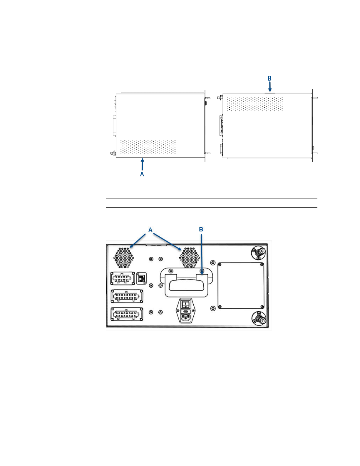
Top and Bottom View - VentilationFigure 1-2:
A. Top ventilation holes
B. Bottom ventilation holes
Plan
Rear View - Ventilation and HandleFigure 1-3:
A. Rear ventilation holes
B. Rear panel handle
3. Inspect the analyzer and ensure the unit is correctly mounted in the rack and glides
easily on the telescoping slide rails.
The analyzer must slide in and out of the rack to make the power, analog, digital,
Ethernet, and gas connections.
1.2.1
Tools required
3

Plan
The CT5400 is shipped as a complete unit and requires minimal tools for installation.
The minimum tools required are:
• 2 (14 mm) spanners (or 2 off adjustable spanners) for gas fittings
• Small flat head screwdriver for wiring electrical contacts
• M5 Hex bit or Alan key
1.3 Detailed system specifications
Table 1-1 gives the physical characteristics of the analyzer. Schematic diagrams of the
sensor and mounting points are shown in , . Table 1-2 gives the general characteristics of
the instrument.
Physical CharacteristicsTable 1-1:
Rosemount CT5400 Value Units Comment
External dimensions 482.6 x 673 x 221.5
19 x 26.5 x 8.7
Weight 31
68.34
mm
in.
kg
lb
Length x Width x Height
Nominal dimensions
Approximate weight
General CharacteristicsTable 1-2:
Rosemount CT5400 Value Units Comment
Supply voltage 240 Vac 50 Hz
Peak power consumption
Continuous steadystate power consumption
Frame and structure
material
Housing material - - Powder coated steel
Wetted materials PFA coated aluminum, 315 stainless steel,
Measurement technique
Mid IR source - - Quantum Cascade Laser
Laser classification Class 1 BS EN 60825-1: 2007 safety of laser products.
600 W Max consumption
300 W Once the gas analyzer has stabilized and the
analysis cell has reached the temperature set
point
- -
- - Mid IR absorption spectroscopy
Anodized and powder coated aluminum
FKM and FFKM seals, CaF2 and BaF2 windows,
protected gold coated aluminum mirrors
Equipment classification and requirements
(identical to IEC 60825-1 2007)
4

General Characteristics (continued)Table 1-2:
Rosemount CT5400 Value Units Comment
Inlet gas port connector
Outlet (exhaust) gas
port connector
Measurement result
signals
Warm-up time 90 minutes
6
1/4
6
1/4
4 to 20 mA 4 or 8 channel outputs, specify on order
mm
in.
mm
in.
Swagelok type, factory-configured, specify on
order
Swagelok type, factory-configured, specify on
order
Dimensions - Front ViewFigure 1-4:
Plan
A. User interface
B. Data extraction port
C. 4 off Ø system locking holes
D. Ventilation. Do not obstruct.
5

Plan
Dimensions - Side ViewFigure 1-5:
A. Handle swings out 63 mm (2.5 in.)
B. 2 off telescopic slide, 610 mm (24 in.) long, 55 kg (121.3 lb.) max load. 50.8 mm (2 in.) over travel.
9.6 mm (.4 in.) slide thickness. Lock-out. Front disconnect.
Dimensions - Top ViewFigure 1-6:
A. Ventilation. Do not obstruct.
Environmental CharacteristicsTable 1-3:
Environmental characteristic Value Units Comment
Operating temperature range 0 to 45
32 to 113
°C
°F
Ambient temperature
6

Environmental Characteristics (continued)Table 1-3:
Environmental characteristic Value Units Comment
Sample gas temperature range 50 to 195
122 to 383
Sample gas particulate density 5 mg/m
Sample gas particulate size 10 μm Maximum
Sensor humidity range 10 to 95 % Relative humidity (non-condens-
Note
The CT5400 Continuous Gas Analyzer is suitable for indoor use only
°C
°F
Factory set, specify on order
3
Maximum
ing) at 45 °C (113 °F)
Plan
7

Plan
8

2 Install
2.1 System overview
A complete Rosemount CT5400 system consists of a gas handling system, the analyzer,
and the associated interconnecting wiring and gas piping.
Measurement data from the analyzer can be displayed in the process control center. You
must provide the gas handling system and interconnecting wiring and gas piping; Emerson
supplies the CT5400.
In Figure 2-1, the items supplied by Emerson are colored orange; the items supplied by you
are colored blue. Table 2-1 lists the main items of the system.
Complete Rosemount CT5400 Gas Analysis SystemFigure 2-1:
Install
A. Gas handling system
B. Sample supply line
C. Sample return (exhaust) line
D. Rosemount CT5400 Gas Analyzer
E. Electrical power
F. Measurement data
G. Control center
The analyzer contains an optical system with multiple lasers and a series of optical
components that provide an optical path, a heated multi-pass analysis cell, and sample
and outlet ports that can be connected to a gas handling system, and control and analysis
electronics. The number of lasers installed depends upon customer requirements. The
complete system operates from a 240 Vac 50 Hz supply.
Gas concentrations are measured using mid-infrared optical absorption spectroscopy. The
light sources are quantum cascade lasers (QCLs), which are operated to produce
wavelength sweeps that cover the absorption lines of the gases. The light from each laser
is routed through an optical path to the analysis cell, which provides measurement of low
concentrations of the subject gases. An external sample handling system conditions the
sample gas and draws it through the analysis cell. The light exits the multi-pass analysis cell
and is directed to a receiver in the analyzer. The variation in the intensity of light in the
vicinity of the absorption lines is measured, and the concentration is determined using a
comprehensive spectral fitting routine.
9

Install
There is no sample conditioning provided within the analyzer; the sampled gas must be
brought within the parameters shown in Section 1.3 before entering the analyzer. Detailed
characteristics of the analyzer are also given in Section 1.3.
Main Items of the Rosemount CT5400 SystemTable 2-1:
Item Name or description Supplied by Part number Quantity Notes
1 Rosemount CT5400 Emerson CT5400 1
2 Rosemount CT5400 software
package, version 5.x.x
3 Gas handling system Customer Customer choice 1
4 Heated gas sample line hose Customer Customer choice 1
5 Exhaust line hose (for sample
gas)
6 Reference gas cylinders (in-
strument gas) for calibration
purposes
7 Pressure regulator Customer Customer choice 1 per gas cylin-
8 Pneumatic T-piece Customer Customer choice 2 Required for
9 Excess flow line Customer Customer choice 1 Required for
10 240 Vac power cable Customer Customer 1
11 Cable from analyzer to con-
trol center
12 482.6 mm (19 in.) rack sys-
tem
Emerson N/A 1 Software is
embedded
in .
Version described in
manual
Customer Customer choice 1
Customer Customer choice Dependent
upon number of
gases being
measured
Required for
der
Customer Customer choice 1 1
Customer Customer choice 1 Holds the
calibration
calibration
calibration
CT5400
2.2 Gas inputs and outputs
The analyzer has one gas input and one gas output, both of which are located on the rear
panel of the instrument (Figure 2-2).
Procedure
1. The gas sample that is to be measured for impurities enters the instrument through
the sample gas input port .
10

2. Once the gas sample has been examined for impurities, it is expelled from the
instrument through the sample gas return port (B).
Gas Inlet and Outlet ConnectorsFigure 2-2:
A. Sample gas input port
B. Sample gas return port
Install
3. The sample supply line must be heated all the way to the sample gas input port on
the analyzer to prevent condensation forming at any point in the sample supply line.
WARNING!
HAZARDOUS GAS
The product stream that the analyzer is examining may be hazardous even at low
concentrations. Therefore, take special care to ensure that the sample gas return port
either returns the sample gas to the product stream or discharges the sample gas to a
location that will not cause a hazard.
11

Install
2.3 Connecting the electrical/electronic inputs and outputs
Electrical / Electronic ConnectorsFigure 2-3:
A. Ethernet connector
B. Ventilation holes
C. Sample supply (stainless steel tubing)
D. Sample return (stainless steel tubing)
E. Main power supply
F. Analog outputs (4-20 mA)
G. Digital outputs
H. Status output (10 way connector)
Electrical/electronic signal connections to the analyzer are made through electrical
connectors located on the rear panel of the instrument, as shown in Figure 2-3.
Status outputs, 10 way socket (H)Table 2-2:
Pins Function
1-6 Status output 1 (check function), optional
2-7 Status output 2 (maintenance required), optional
3-8 Status output 3 (out of specification), optional
4-9 Status output 4 (failed), optional
12

Digital outputs, 16 way socket (G)Table 2-3:
Pins Function
1-9 Reading valid channel 0, set in config file
2-10 Reading valid channel 1, set in config file
3-11 Reading valid channel 2, set in config file
4-12 Reading valid channel 3, set in config file
5-13 Reading valid channel 4, set in config file
6-14 Reading valid channel 5, set in config file
7-15 Reading valid channel 6, set in config file
8-16 Reading valid channel 7, set in config file
Analog outputs, 16 way socket (F)Table 2-4:
Pins Function
1-9 Analog channel 0, set in config file
2-10 Analog channel 1, set in config file
3-11 Analog channel 2, set in config file
4-12 Analog channel 3, set in config file
5-13 Analog channel 4, set in config file
6-14 Analog channel 5, set in config file
7-15 Analog channel 6, set in config file
8-16 Analog channel 7, set in config file
Install
CAUTION!
EQUIPMENT DAMAGE
Make sure that the mains supply cable used is of a suitable rating for the unit power
requirements. Failure to do so may result in damage to property.
The Ethernet connector (Figure 2-3, A) provides an Ethernet output from the instrument
that may be used for downloading data for failure diagnosis purposes.
The results of the gas analysis are output from the instrument through the 4-20 mA analog
outputs (Figure 2-3, F) and sent to your process control center.
The status outputs (H) provide fault indications to your process control center. Each digital
output is connected to a normally closed relay, located inside the analyzer, which will open
in response to the detection of a specific fault. The possible causes of a fault indication are:
1. The sample gas concentration is outside of specification, i.e., the sample gas
concentration has exceeded the measurement range of the instrument.
2. The analyzer is out of specification or has developed a fault.
13

Install
WARNING!
HIGH VOLTAGE
Voltages up to 250 Vac, 50 Hz may be present on the digital output terminals.
External circuits should be installed in accordance with national wiring regulations.
Failure to obey the wiring regulations may result in serious injury to personnel.
WARNING!
ELECTRIC SHOCK
The analyzer passed electromagnetic compatibility (EMC) tests based on all electrical cables
and harnesses attached to the instrument having a length of 3 m (9.8 ft.) Attaching cables and
wiring harnesses longer than 3 m (9.8 ft.) may cause injury to personnel.
14

Navigating the CT5400 Controls
3 Navigating the CT5400 Controls
3.1 Front panel controls and indicators
There are two controls located on the front panel ():
Front panelFigure 3-1:
A. Display controller
B. Illuminated On/Off switch
The front panel On/Off switch (Figure 3-1, B) controls the application of electrical power to
the electronic circuits inside the instrument. On the switch, I identifies the On position and
O identifies the Off position. The switch includes an indicator that illuminates red when the
switch is set to On.
Note that setting the front panel On/Off switch to Off does not remove all electrical power
from the instrument. Part of the power distribution circuit will remain live. To remove all
electrical power from the instrument, set the On/Off switch on the rear panel (refer to
Section 3.2) to Off.
Operation of the analyzer is controlled primarily through the display controller (Figure 3-2).
15

Navigating the CT5400 Controls
Display controllerFigure 3-2:
3.2 Rear panel controls
There is only one control on the rear panel , a fused socket (A) that incorporates an
switch. The function of the rear panel On/Off switch is to control the application of
electrical power to the complete instrument.
Rear PanelFigure 3-3:
On/Off
16
A.
On/Off switch - fused socket

3.3 Display controller
Front Panel Display ControllerFigure 3-4:
A. LCD display
B. Navigation buttons
Navigating the CT5400 Controls
The LCD display (A) can be used to display:
1. Gas concentration measurements obtained
2. Operating temperature and pressure
3. Help screens
4. Step-by-step calibration
5. Diagnostics
The navigation buttons (B) are configured to perform different functions according to
which software screen is shown on the LCD display.
Display Controller Navigation Button FunctionsTable 3-1:
Button Description
Normally used to scroll up. Referred to as UP.
Normally used to scroll down. Referred to as DOWN.
Normally used to select. Also accesses the Main Menu from the Home screen.
Referred to as RIGHT.
Used to go back to the previous screen. No function from the Home screen. Referred to as LEFT.
Used to access the context sensitive Help pages. Referred to as HOME.
Generally used to select an alternative function. Also allows you to toggle between gas and physical measurements from the Home screen. Referred to as
ENTER.
17

Navigating the CT5400 Controls
The analyzer employs Intelligent Device Management which enables self-monitoring and
diagnostics. This ensures that operators are made aware of malfunctions so they can take
appropriate action. Table 3-2 defines the symbols that may be displayed.
Diagnostic symbolsTable 3-2:
System running
Maintenance required: still valid output signal
Out of specification: signal out of the specified range
Indicates the analyzer is performing a calibration or validation or that the software has been deliberately stopped.
Failure: non-valid output signal
3.4 Gas Sensor Main screen
When the analyzer is switched on, at the end of the startup procedure, the Gas Sensor Main
screen (Figure 3-5) appears. The Gas Sensor Main screen is the screen that is normally
displayed.
NOTICE
The gas concentrations shown in the following screenshots may be different from those shown
in your particular analyzer. The screenshots indicate the functionality of the software, which is
the same regardless of the gases or gas concentrations being measured.
Gas Sensor Main screenFigure 3-5:
18
The Gas Sensor Main screen displays the gas concentration measurements obtained by the
analyzer. In the example shown in , the gases are being measured, and for each gas, the
concentration detected is in parts per million (ppm).

At the end of the startup procedure, the gas measurements initially appear as 0.00 until
the first readings are taken. After a few seconds, the initial gas concentrations are
displayed.
The Gas Sensor Main screen also shows the status of the analyzer. In the example shown in ,
the instrument is Running and OK (i.e., no faults have been identified).
is a link to the Help system. Press to go to Help screen (described in Section 3.6).
On the Gas Sensor Main screen, has no function when the analyzer is operating correctly. If,
however, the software detects a fault, an error message is displayed. Press to get further
information on the error.
3.5 Pressure and Temperature screen
The Pressure and Temperature screen (Figure 3-6) shows pressure and temperature
measurements taken inside the analyzer.
Pressure and Temperature ScreenFigure 3-6:
Navigating the CT5400 Controls
3.6
The Cell reading is the temperature, in °C, of the analysis cell.
The Press reading is the pressure, in Torr, inside the analysis cell.
NOTICE
A Torr is a non-SI unit of pressure defined as 1/760 of standard atmospheric pressure and is
equal to the fluid pressure of 1 mm of mercury.
Help system
The analyzer software includes a context-sensitive help system. Press , which is
available on most of the software screens, to open the Help system.
19

Navigating the CT5400 Controls
The help system contains a number of different Help screens, each conveying a different
message. As the help system is context-sensitive, the help screen that appears is the one
that is most appropriate to the software function engaged when
Figure 3-7 shows an example of a help screen.
Example of a Help ScreenFigure 3-7:
3.7 Main menu
was pressed.
To access the Main menu (Figure 3-8), press on either the Gas Sensor Main screen
(Figure 3-5) or the Pressure and Temperature screen (Figure 3-6). The Main menu options are:
• DIAGNOSTICS: Displays various parameters used in the internal calculations and
compares desired and actual parameters, for example, the analysis cell pressure and
temperature. The diagnostics routines and screens are used to perform fault
diagnosis.
• FAULTS: Takes you to a screen that lists any faults affecting the analyzer. This option
is used as part of the failure diagnosis procedures.
• GAS SERVICE: Allows you to check the sensor readings against a known gas source
(verification) or, if necessary, to calibrate the analyzer against that known gas source
(calibration).
• DATA SERVICE: Takes you to a screen that allows data to be downloaded from the
instrument. The downloaded data is used to diagnose faults.
• SYSTEM: Takes you to a screen that allows you to shut down the analyzer or access
system information, such as software versions or IP addresses. The main
motherboard IP address can also be changed from this menu. Some of these options
are not available on older analyzers.
20

Main menuFigure 3-8:
3.8 BACK button
Navigating the CT5400 Controls
On most of the software screens, is configured as a BACK button. Press to return to
the previous screen.
21

Navigating the CT5400 Controls
22

4 Startup procedure
4.1 Introduction
CAUTION!
EQUIPMENT DAMAGE
Always follow the startup procedure. Damage to the Rosemount™ CT5400 may result from a
failure to follow this procedure.
The Rosemount CT5400 normally operates continuously. It should only be necessary to
start up the instrument under the following circumstances.
• When the Rosemount CT5400 is first switched on following installation.
• Following repair or maintenance.
• When it has been switched off as part of a plant shutdown or maintenance.
Startup procedure
4.2 Preparation for use
The analyzer must be installed and fully commissioned prior to startup.
CAUTION!
EQUIPMENT DAMAGE
Do not power up or try to operate the analyzer unless it is physically secure and all electrical
and pneumatic connections to the analyzer are in place.
Before commencing the start-up process, it is important to ensure that electrical power,
sample gas handling facilities, and any calibration gases that are required are available to the
analyzer.
WARNING!
BURNS
Do not touch any part of the analyzer. Assume all parts of the analyzer are hot unless it has
been switched off and allowed to cool down. Some parts of the analyzer may be heated to
190 °C (374 °F). Always wear proper protective equipment when handling the analyzer.
• Switch off the analyzer and allow it to cool for at least two hours before fitting,
removing, or performing any maintenance.
• The analysis cell is insulated against heat loss. Allow the analyzer to cool for at least
twelve hours before performing any maintenance on, or in the vicinity of, the analysis
cell.
Failure to allow sufficient cooling may cause serious burn injury to personnel. If burns occur,
seek immediate medical treatment.
23

Startup procedure
4.3 Startup procedure
NOTICE
The gases shown in the screenshots and the measurements thereof may be different from
those shown in your particular analyzer. They indicate the functionality of the software, which
is the same regardless of the gases being measured.
NOTICE
To stop the startup procedure at any time, set the main circuit breaker to OFF.
To start up the analyzer, perform the following steps:
Procedure
1. Visually inspect the exterior of the analyzer for signs of damage, corrosion, gas
leaks, or overheating. Report anything found to the maintenance organization.
2. Make sure that the analyzer has been correctly installed (see Chapter 2).
3. Make sure that the rack lid is fitted to the analyzer. If it is not, report it to the
maintenance organization and do not proceed further until the rack lid has been
fitted.
4. Make sure that the On/Off switch at the rear of the analyzer is set to I (ON).
5. On the front panel (Figure 4-1) of the analyzer, set the On/Off switch (B) to I (ON).
Check that the switch illuminates.
Front panelFigure 4-1:
A. Display controller
B. Illuminated On/Off switch
The startup sequence commences automatically under software control.
24

Startup procedure
After a few seconds, the Gas Sensor Main screen (Figure 4-2) appears on the display
controller. If it does not, report the fault to the maintenance organization.
Gas Sensor Main screenFigure 4-2:
6. Start up the system for returning the sample gas.
7. Start up the gas handling system that conditions the sample gas before it is fed into
the analyzer. Allow the analyzer to warm up in accordance with Table 1-2 before the
sample gas supply is turned on.
25

Startup procedure
26

Startup procedure
27

CASCADE TECHNOLOGIES
Glendevon House
Castle Business Park
Stirling FK9 4TZ
Scotland
+44 1786 447 721
+44 1786 475 822
qcl.csc@emerson.com
D-7010-0061
Rev C
2018
AMERICAS
Emerson Automation Solutions
10241 West Little York, Suite 200
Houston, TX 77040 USA
Toll Free 866 422 3683
+1 713 396 8880 (North America)
+1 713 396 8759 (Latin America)
+1 713 466 8175
qcl.csc@emerson.com
EUROPE REGIONAL OFFICE
Emerson Automation Solutions
Neuhofstrasse 19a PO Box 1046
CH-6340 Baar
Switzerland
T +41 (0) 41 768 6111
F +41 (0) 41 768 6300
qcl.csc@emerson.com
Linkedin.com/company/Emerson-Automation-Solutions
twitter.com/rosemount_news
Facebook.com/Rosemount
youtube.com/RosemountMeasurement
google.com/+RosemountMeasurement
AnalyticExpert.com
MIDDLE EAST AND AFRICA REGIONAL
OFFICE
Emerson Automation Solutions
Emerson FZE
Jebel Ali Free Zone
Dubai, United Arab Emirates, P.O. Box 17033
T +971 4 811 8100
F +971 4 886 5465
qcl.csc@emerson.com
©
2017 Rosemount. All rights reserved.
The Emerson logo is a trademark and service mark of Emerson Electric Co. Rosemount is a
mark of one of the Emerson family of companies. All other marks are the property of their
respective owners.
ASIA-PACIFIC REGIONAL OFFICE
Emerson Automation Solutions
1 Pandan Crescent
Singapore 128461
Republic of Singapore
T +65 6 777 8211
F +65 6 777 0947
qcl.csc@emerson.com
 Loading...