

Page 1
User Manual
QCL-MAN -CT2211-Aerosol-Leak-Detection-System, Rev F
October 2015
CT2211 Aerosol Leak Detection System
Page 2
Preface
All possible care has been taken in the preparation of this publication, but Cascade Technologies and its
agents and distributors accept no liability for any inaccuracies that may be found. This user manual reflects
the state of the product at the issue date below, but further enhancements while in service may mean that the
user manual does not reflect your particular system.
Cascade Technologies reserves the right to make changes without notice both to this publication and the
products which it describes.
No part of this publication may be reproduced, stored in a retrieval system, or transmitted in any form or by
any means electronic, mechanical, photocopying, recording, or otherwise without the express prior written
permission of the copyright holder.
Contact Details:
Cascade Technologies Limited.
Glendevon House
Castle Business Park
Stirling
FK9 4TZ
United Kingdom
General inquiries about this or other Cascade Technologies products should be sent to qcl.csc@emerson.com.
If you require technical assistance with this product that is not covered within this user manual, then help can
be requested from Cascade Technical Support (qcl.csc@emerson.com) or Cascade Technologies distribution
partners.
All trademarks used within this document are the property of their respective owners.
Only for EC countries:
Do not dispose of measuring tools into household waste!
According the European Guideline 2002/96/EC for Waste Electrical and Electronic Equipment and its
implementation into national right, measuring tools that are no longer usable must be collected
separately and disposed of in an environmentally correct manner.
Page 3

User Manual Table of Contents
QCL-MAN- CT2211-Aerosol-Leak-Detection-System-Rev F October 2015
Table of Contents
Section 1:Introduction ................................................................................................ 1
1.1 Qualified personnel ........................................................................................ 1
1.2 Safety ......................................................................................................... 1
1.3 Certifications and approvals ........................................................................... 2
1.4 System overview ............................................................................................ 2
1.5 Leak detector overview .................................................................................. 5
1.6 Detailed system specification ......................................................................... 6
1.7 Operators’ system pre startup checklist ......................................................... 7
Section 2:System Connection ...................................................................................... 8
Section 3:System Startup .......................................................................................... 12
Section 4:Shutdown ......................................................................................... ......... 14
Section 5: Operation .................................................................................................. 15
5.1 Software screens .......................................................................................... 15
5.1.1 Home screen — aerosol leak detection system .............................. 15
5.1.2 User Login screen ........................................................................ 16
5.1.3 Program Page .............................................................................. 17
5.1.4 Error Status page ......................................................................... 18
5.1.5 CT2211 Main Screen .................................................................... 19
5.1.6 CT2211 Graphs Screen ................................................................ 20
5.1.7 Digital IO Status page .................................................................. 21
5.1.8 Optical Gates page ...................................................................... 22
5.1.9 Rejector page .............................................................................. 23
5.1.10 Line Speed page .......................................................................... 24
5.2 Errors ....................................................................................................... 24
5.2.1 Overall system healthy ................................................................. 24
5.2.2 Leak detector (CT2211) system healthy ....................................... 25
5.2.3 Leak detector (CT2211) laser healthy ........................................... 25
5.2.4 Can lost ....................................................................................... 25
5.2.5 Can found .................................................................................... 25
5.2.6 Too many consecutive rejects ...................................................... 25
5.2.7 Reject verification ........................................................................ 26
5.2.8 Encoder error ........................................... ........... ............... .......... 26
5.2.9 Air sampling healthy .................................................................... 26
5.2.10 Bin full ...................................................................................... 26
5.2.11 Mirror purge warning ................................................................... 26
5.2.12 Mirror purge error ........................................................................ 26
5.2.13 Repeatable reject error ................................................................ 27
5.2.14 Compressed air error ................................................................... 27
5.2.15 Error Flags 14/15 ......................................................................... 27
5.3 Line PLC communication .............................................................................. 27
5.3.1 Linestop (in) ................................................................... 28
5.3.2 System shutdown signal (in) ........................................... 28
5.3.3 Linestop 1 and linestop 2 (out) ........................................ 28
5.3.4 Heartbeat signal (out) .................................................. ... 28
5.3.5 Reject counter pulse (out) .............................................. 28
5.4 Control system programs ............................................................................. 29
5.4.1 Add Programs ................................................................. 30
Section 6:Maintenance ......................................................... ........................... .......... 31
6.1 Schedule ......................................... ............................................... .............. 31
6.1.1 Daily ................................................... ............................ 31
6.1.2 Weekly ........................................................................... 31
Table of Contents i
Page 4

Table of Contents User Manual
October 2015 QCL-MAN- CT2211-Aerosol-Leak-Detection-System-Rev F
6.1.3 Monthly ................................................. ......................... 31
6.2 Analysis system ............................................................................................ 31
6.3 Venturi ....................................................................................................... 32
6.4 Replacement parts ....................................................................................... 32
Section 7:Troubleshooting and Diagnostics ............................................................... 33
7.1 Warning and error messages ........................................................................ 33
Table of Contents ii
Page 5

User Manual List of Tables
QCL-MAN -CT2211-Aerosol-Leak-Detection-System-Rev F October 2015
List of Tables
Table 1-1 Leak detection system specifications .................................................... 7
Table 5-1 IO lines ................................................. .............................................. 28
Table 6-1 Aerosol leak detection system replacement parts list ......................... 32
Table 7-1 Possible problems and solutions ......................................................... 33
List of Tables iii
Page 6

List of Figures User Manual
August 2015 QCL-MAN -CT2211-Aerosol-Leak-Detection-System-Rev F
List of Figures
Figure 1-1 Aerosol leak detection system - Venturi configuration .......................... 3
Figure 1-2 Aerosol leak detection system - blower configuration ........................... 4
Figure 1-3 Monitoring aerosol cans for leaks on a conveyer ................................... 5
Figure 2-1 Schematic of I/O and external connections ........................................... 8
Figure 2-2 Filter assembly and archway quick connector ....................................... 9
Figure 2-3 Air preparation plate .......................................................................... 10
Figure 2-4 Left: Sensor head, Right: Air extraction arch assembly ........................ 11
Figure 3-1 Isolation switch .................................................................................. 12
Figure 3-2 Control system display ....................................................................... 13
Figure 5-1 Control system Home screen ............................................................. 15
Figure 5-2 User login screen ................................................................................ 16
Figure 5-3 Program Page screen ......................................................................... 17
Figure 5-4 Error Status screen ............................................................................. 18
Figure 5-5 CT2211 Main Screen .......................................................................... 19
Figure 5-6 CT2211 Graphs Screen ....................................................................... 20
Figure 5-7 Digital IO Status screen ...................................................................... 21
Figure 5-8 Optical Gates page ............................................................................. 22
Figure 5-9 Rejector page ..................................................................................... 23
Figure 5-10 Line Speed page ................................................................................. 24
Figure 5-11 PLC connections ................................................................................. 27
Figure 5-12 Program Page .................................................................................... 29
Figure 5-13 Add programs screen ......................................................................... 30
Figure 7-1 Network status ................................................................................... 34
Figure 7-2 12V PSU status ................................................................................... 34
Figure 7-3 Circuit breaker ................................................................................... 35
Table of Contents iv
Page 7

User Manual Introduction
QCL-MAN -CT2211-Aerosol-Leak-Detection-System-Rev F October 2015
1 Introduction
The aerosol leak detection system described in this document has been quality control
tested and left the manufacturer in pristine condition. To achieve the correct and safe
operation of the product, it must be transported, installed, operated, and maintained
as described by the manufacturer.
This manual contains all the information required to operate the leak detection
system, including basic maintenance and troubleshooting information. Please read the
manual carefully before you start work on the leak detection system, as it contains
important information that must be followed to guarantee the correct operation of
the system and the safety of personnel. The manual is divided into sections, which
allows you to rapidly find the information you need.
Cascade Technologies is committed to continuously improving its products and
documentation. Every effort will be made to include any sensor modifications by the
manufacturer in the documentation. However, it should be noted that this document
reflects the supplied sensor as of the revision number and date on the front cover.
Should you require further information or should particular problems arise that are not
covered within this user manual, then refer to the Leak Detection System Installation
and Service Manual. Additional help can also be requested from Cascade Technical
Support (qcl.csc@emerson.com) or Cascade Technologies distribution partners.
1.1 Qualified personnel
These operating instructions have been prepared for technically qualified personnel
who have been specially trained or who possess appropriate knowledge in the field of
instrumentation and control.
Knowledge of the safety information within this user manual and its technically correct
implementation are prerequisites for danger-free installation, commissioning,
operation and maintenance of the system. Only qualified persons have the required
specific knowledge to correctly interpret the general safety information and warnings
given in this user manual and thus apply them to the particular application.
1.2 Safety
During the manufacturing process of the aerosol leak detection system, a rigorous set
of safety and quality checks is performed to ensure that the equipment meets and
exceeds the safety requirements for the system. In order to maintain the operational
performance and safety of the control system, the correct installation, use, and
maintenance procedures detailed by the manufacturer must be adhered to.
The aerosol leak detection system uses no ionizing radiation.
Certain parts of the Leak Detection system carry dangerous voltages. All housings
must be closed with covers in place and the sensor head mounted and connected to
the air arch before switching on. Death, personal injury, and/or damage to persons
and/or property may result if this is not observed.
Introduction 1
Page 8
Introduction User Manual
October 2015 QCL-MAN-CT2211-Aerosol-Leak-Detection-System-Rev F
Use of controls or adjustments or performance of procedures other than those
specified herein may result in hazardous radiation exposure.
All lasers used within the leak detection system are of class 1. The emitted laser light is
invisible (mid-infrared) and the pulse duration so short that the unprotected eye will
not be damaged. The nature of the laser beam path and beam width furthers ensures
that it should be impossible to cause any eye damage. The leak detection system has
warning labels at appropriate positions according to USA 21 CFR 1040.10.
1.3 Certifications and approvals
All in zone parts comply with the ATEX directive (94/9/EC).
This leak detector complies with USA 21 CFR 1040.10. It is
also designed and manufactured under an approved
quality management system to ISO 9001:2008.
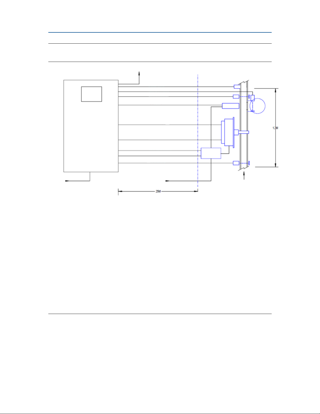
1.4 System overview
The aerosol leak detector is used on aerosol production lines in conjunction with a
control and reject mechanism, to form the aerosol leak detection system, which is
used to manage the interaction with the line and the safe removal of faulty cans at
high speed. The system consists of a detector, control console (non-ATEX), encoder,
optical gates, rejecter (air based reject as standard), reject chute, air preparation
equipment, and mounting mechanics. Figure 1-1and Figure 1-2 below show the
schematic of the leak detection system:
Introduction 2
Page 9
User Manual Introduction
U.
N
QCL-MAN -CT2211-Aerosol-Leak-Detection-System-Rev F October 2015
Figure 1-1 Aerosol leak detection system - Venturi configuration
A. HMI
Micro leak control console
B. System DC power supplies (+12V & +24V). System controlling PC Windows OS. Micro leak
D
and control system software. National instruments digital I/O and digital
timing card. Line driver and opto barrier circuitry. Customer Line PLC interface.
Circuit protection. AC power control. Console thermal management and
A
control.
Out of zone
components
E
F
G
H
C. AC supply voltage 110V/220V AC, 50-60HZ 13A (customer supplied)
Rated components
O
P
Q
— zone 2
D. Line status signals to customer comms (running, waiting, error)
E. Encoder signal
F. Rejected can signal
G. Output gate signal
B
H. Reject signal
I. CT2211 comms (cat5)
J. CT2211 I/O and power
I
J
R
K
L
M
S
T
K. Mirror cleaning signal
L. Air status signal
C
M. Input gate signal
Line direction
N. Compressed air supply min 5 BAR, max 10 BAR (customer supplied)
O. Encoder
Max cable run
P. Output gate
Q. Reject
Input gate signal
A. HMI
B. Leak Detection System
1
N. Compressed air supply min 5 BAR, max 10 BAR
M.
(customer supplied)
U
V
C. AC supply voltage 110V/220V AC, 50-60 Hz
13A (customer supplied)
D. Line status signals to customer
communications
(running, waiting, error)
E. Encoder signal Q. Reject
F. Rejected can signal R. Micro leak detector
G. Output gate signal S.
H. Reject signal T. Input gate
I. CT2211
J. CT2211 I/O and power V. Reject bin (customer supplied)
K. Mirror cleaning signal
L. Air status signal
communications (cat5)
Encoder
O.
P.
Output gate
Air status air control
Rejected can gate
1
The leak detection system components are: DC power supplies (+12V & 24V); system controlling PC with
Microsoft® Windows operating system; micro leak and control system software; national instruments digital I/O and
digital timing card; line driver and opto barrier circuitry; customer line PLC interface; vircuit protection; AC power
control; and console thermal management and control.
Introduction 3
Page 10

Introduction User Manual
J
X
E
H I J
—
October 2015 QCL-MAN-CT2211-Aerosol-Leak-Detection-System-Rev F
Figure 1-2 Aerosol leak detection system - blower configuration
D
leak control console
Micro
Out of zone
Rated components
components
P
A
F
G
Q
zone 2
X
B
K
L
M
N
C
O
V
Max cable run
A. HMI
B. Leak detection system
C. AC supply voltage 110V/220V AC, 50-60 Hz
13A (customer supplied)
D. Line status signals to customer
communications (running, waiting, error)
E. Encoder signal
F. Rejected can signal R. Reject.
G. Output gate
H. Reject signal T. Air status air control
I. CT2211 communications (cat5) U. Input gate
. CT2211
K. Mirror cleaning signal W. ATEX zone 2 rated blower
L. Air status signal
Y. Reject bin (customer supplied)
signal S. Micro Leak detector
I/O and power V. ATEX zone 2 disconnect switch
2
N. Compressed air supply min 5 BAR, max 10 BAR
M. Input gate signal
(customer supplied)
O. Phase controlled power
P. Encoder
Q. Output gate
. Rejected can gate
R
Y
S
T
U
W
Line direction
2
The leak detection system components are: DC power supplies (+12V & 24V); system controlling PC with
Microsoft® Windows operating system; micro leak and control system software; national instruments digital I/O and
digital timing card; line driver and opto barrier circuitry; customer line PLC interface; circuit protection; AC power
control; and console thermal management and control.
Introduction 4
Page 11

User Manual Introduction
QCL-MAN -CT2211-Aerosol-Leak-Detection-System-Rev F October 2015
1.5 Leak detector overview
The leak detector identifies aerosol cans that are leaking propellant as they are carried
along a conveyor belt at high speed. The leak detector consists of an air extraction
arch, air filter/regulator, sample cell, sensor head and either a Venturi or 3-phase
blower.
Figure 1-3 Monitoring aerosol cans for leaks on a conveyer
D
B
A
C
E
A. Air extraction arch — draws the air from around the aerosol can into the
sample handling system
B. Air filter — for the removal of air particles and leaked contents of the
aerosol cans
C. Sample cell — laser light is directed through the air extracted from around
the cans and back into the sensor head.
D. Sensor head — contains the lasers and laser light detector. It is ATEX
Category 3 rated for a Zone 2 explosive environment.
E. Conveyor belt — transporting the aerosol cans
Aerosol cans (not shown) are moving along the conveyor belt.
The control console (not shown) is located outside the explosive environment and is
not ATEX rated.
Introduction 5
Page 12

Introduction User Manual
October 2015 QCL-MAN-CT2211-Aerosol-Leak-Detection-System-Rev F
The power supply (not shown) for the sensor is also mounted outside the explosive
environment.
The Venturi (not shown) is powered by compressed air and mounted in the exhaust
line below the sample cell. It is used to draw air from around the aerosol cans via the air
extraction arch.
The 3-phase blower (not shown) is powered from the control cabinet and mounted in
the exhaust line below the sample cell. It is used to draw air from around the aerosol
cans via the air extraction arch.
The Venturi air status pressure switch (not shown) signals a third party controller if the
air pressure drops below that required by the Venturi.
Gas concentrations are measured using mid-infrared optical absorption spectroscopy.
The light sources are quantum cascade lasers, which are operated to produce
wavelength sweeps that cover the absorption lines of the gases.
The lasers are mounted in the leak detector, and light is directed into the sample cell,
where it is partially absorbed by the gas from the stack. The reflected light from the
cell is detected by a receiver in the leak detector. The variation in the intensity of the
light in the vicinity of the absorption lines is measured, and the concentration is
determined using a comprehensive spectral fitting routine.
Introduction 6
Page 13
User Manual Introduction
x
QCL-MAN -CT2211-Aerosol-Leak-Detection-System-Rev F October 2015
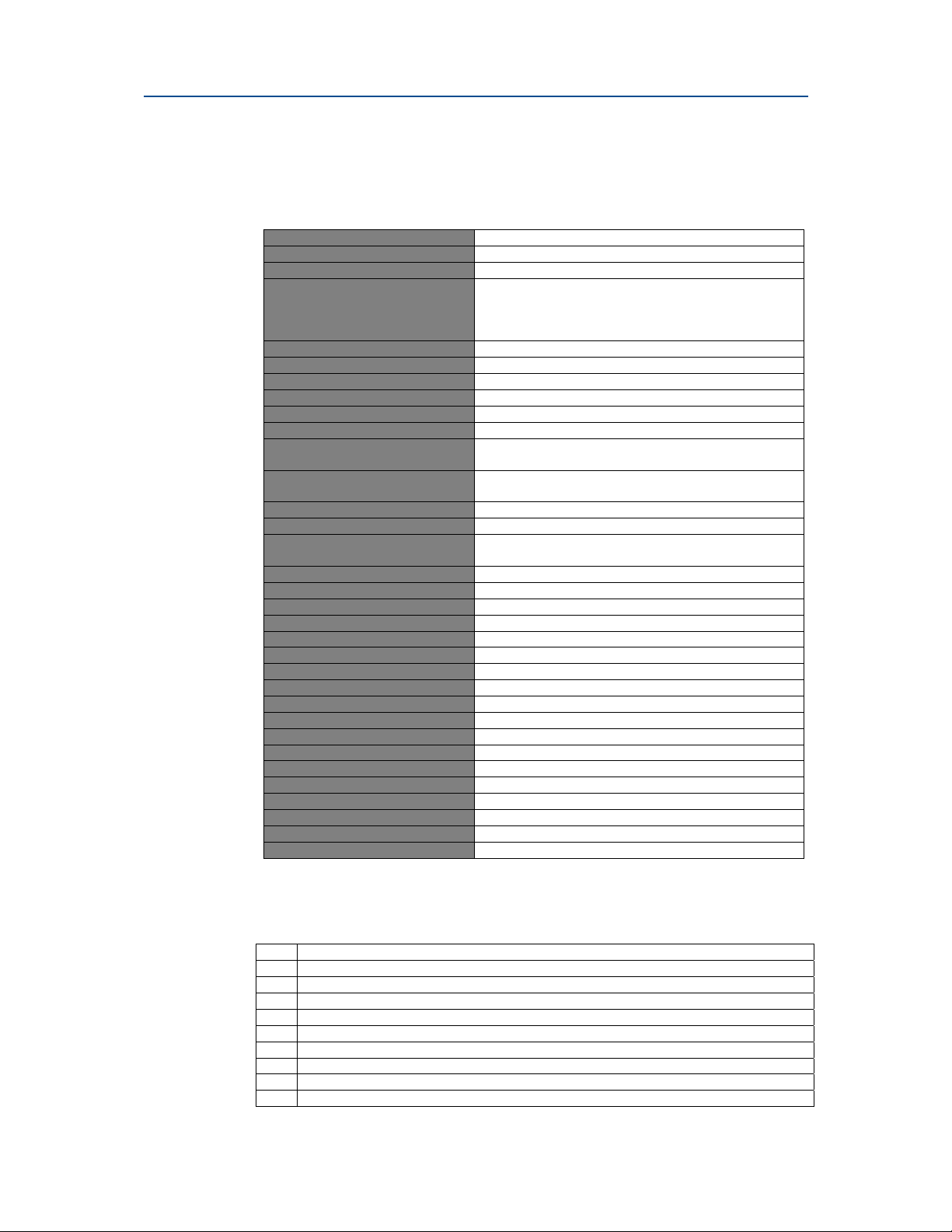
1.6 Detailed system specification
The following table shows the general characteristics of the leak detection system.
Table 1-1 Leak detection system specifications
Application Leak detection system
Measurement technique
IR source Quantum cascade laser
Laser classification Class1
Sensitivity 2 X 10
Line speed Up to 500 cpm
Can dimensions Up to 350 mm (H) by 80 mm (D)
Response time 20 ms
Temperature range 10 — 30 °C (50 — 86 °F)
Sample gas temperature range Room temperature
Leak detector humidity range 10 to 95 % relative humidity (non-condensing) at 35 °C
ATEX Approvals (in zone sensor) Zone 2 Ex II 2G Ex nR II T6 (10 °C≤T
Leak detection system CE approved
Protection class IP65
Hazardous area classification Ex II 3G Ex nR II T6 (10 ° C ≤ T
Analog signal out n/a
Analog signal in n/a
Digital signal out 3 X normally closed contact
Digital signal in 10/100 Base T ethernet
Inlet gas port connector ¾ in. BSPT
Exhaust gas port connector ¾ in. BSPT
Power supply 120 VAC 60 Hz/240 VAC 50 Hz 200 W/A
Control console size 1,200 x 600 x 560 mm (H x W x D)
Control console weight 70 kg
Sensor head size 590
Sensor head weight
Installation On production line
System operating voltage
System power consumption
Max factory air consumption
Factory compressed air pressure 8-10 bar, clean, dry, and oil free
Line space requirement 1.2 m straight free line (maximum)
Air filter particulate filter 2 um, inline filter/regulator required
IR absorption spectroscopy
BS EN 60825-1:2007 Safety of laser products
Equipment classification and requirements (identical to
IEC 60825-1 2007)
-3
(95 °F)
(50 °F≤T
(50 °F≤T
330 x 330 mm (H x W x D) sensor only
20 kg (sensor only)
110 — 240 V AC 50 -60 Hz, specify on order
600 W maximum power requirement
25 L/min approximately on regular usage
mbar.L
≤ 86 °F)
amb
≤ 86 °F)
amb
-1
≤30 °C)
amb
≤ 30° C)
amb
1.7 Operators’ system pre startup checklist
Remove hose from air line.
Check and bleed air line.
Check filter condition and color before switching on system.
Change filter if more than 60% discolored.
Ensure that there are no cans between the input and output gates.
Power on system.
Power on conveyor; do not let cans though.
Clear any error messages, e.g., encoder.
Purge air in chamber
Let cans through to commence normal working activity.
Introduction 7
Page 14

System Connection User Manual
0V
y
y
y
j
p
p
p
p
y
p
p
p
p
p
y
y
p
y
g
j
p
p
g
p
October 2015 QCL-MAN-CT2211-Aerosol-Leak-Detection-System-Rev F
2 System Connection
The diagram below shows the electrical connections of the aerosol leak detection
system:
15 way dtype
plug connects to
15 way dtype
socket on
Cascade opto
box.
Figure 2-1 Schematic of I/O and external connections
System I/O, External Component Connection and Customer Interface
DC
+24V
stem healthy
S
Laser health
Venturi health
In
Out
Re
ect signal
Return
ut gate
Return
ut gate
CASCADEOPTOBOX
CT2211
DC power
plug
9 way
dtype plug
15 way d type
IN 4
IN 5
IN 7
IN 6
Interface
socket
9 way dtype
15 way dtype
see above
OUT0
OUT1
OUT4
OUT3
Air status
socket
IN 2
IN 1
IN 3
Connects to Reject gate
Connects to Reject valve
Connects to Purge valve
ate
ut
Connects to In
System interface card
Status lam
s
Connects to Output gate
Connects to status lam
s
Encoder O
Connects to encoder
SCSI interface from NI PCI6601 card
(68 way ribbon cable)
IN14
IN13
IN12
IN11
IN10
OUT13
stem
are
are
Shutdown s
Line sto
S
S
+24V signals to customer PLC
Inputs to control system: 20 — 25
Outputs to control system: 26 - 31
OUT
10
OUT
7b
OUT9
OUT8
are
S
Return
SCSI
stem health
nal
2 laser health
ulse count
1 control s
ect
are
Linesto
Heartbeat si
Re
Return
Linesto
S
Cascade opto box power
Connects to 9 way socket
Connects to 15 way socket
Cascade CT2210 sensor
Connects to 15 way dplug
Cascade opto box power
Connects to 9 way dsocket
System Connection 8
Page 15

User Manual System Connection
QCL-MAN -CT2211-Aerosol-Leak-Detection-System-Rev F October 2015
The air arch is connected to the leak detector using the attached quick fit connector:
Figure 2-2 Filter assembly and archway quick connector
C
A
B
A. Filter assembly
B. Air arch
C. Leak detector quick fit connector
System Connection 9
Page 16

System Connection User Manual
October 2015 QCL-MAN-CT2211-Aerosol-Leak-Detection-System-Rev F
The filter regulator, pressure switch, and valve shown below are mounted onto the
leak detector pedestal stand.
Figure 2-3 Air preparation plate
B
C
A
D
A. Filter regulator
B. Pressure switch
C. Valve
D. Water separator
System Connection 10
Page 17

User Manual System Connection
A
QCL-MAN -CT2211-Aerosol-Leak-Detection-System-Rev F October 2015
The leak detector is comprised of the following components:
Figure 2-4 Left: Sensor head, Right: Air extraction arch assembly
B
A. Sensor head unit
B. Air extraction arch
System Connection 11
Page 18
System Startup User Manual
October 2015 QCL-MAN-CT2211-Aerosol-Leak-Detection-System-Rev F
3 System Startup
The aerosol leak detection system must be installed and fully commissioned prior to
customer operation.
Ensure that all cables are correctly terminated and the components on the production
line are correctly mounted. The control console must also be securely mounted with
clear access around. The shutdown signal from the line PLC must be set to not switch
the system off otherwise the system will begin to shutdown straight after booting.
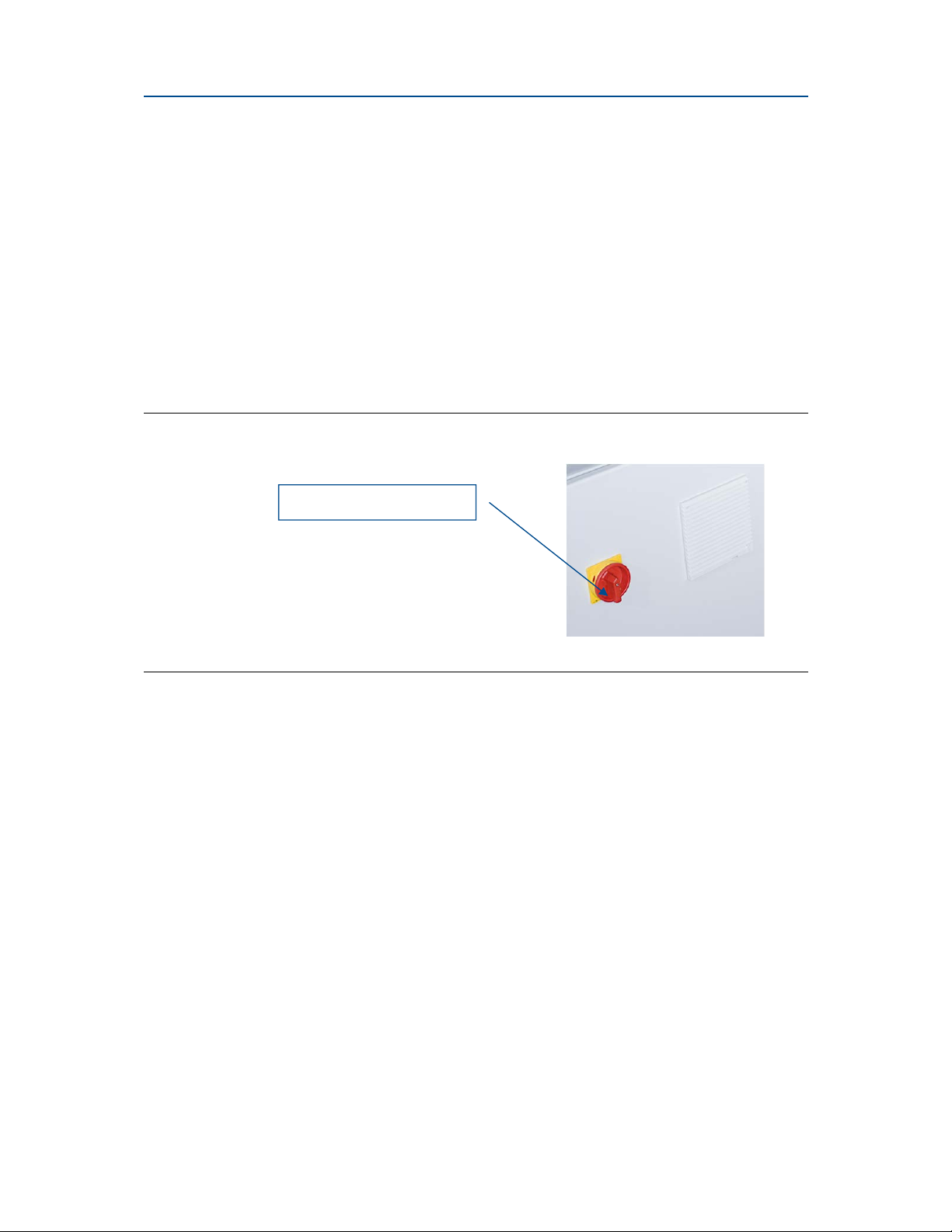
The system is activated by turning the isolation switch (shown below) to the ON
position. The system must have been off for at least 30 seconds in order to boot
correctly.
Figure 3-1 Isolation switch
Isolation switch
System Startup 12
Page 19

User Manual System Startup
QCL-MAN -CT2211-Aerosol-Leak-Detection-System-Rev F October 2015
The Micro Leak Control System initialization takes approximately two minutes after
power is applied.
Figure 3-2 Control system display
The message box at the bottom of the screen indicates any errors or warnings
detected during the boot sequence. If the system has successfully booted, the traffic
light indicator in the bottom right of the screen goes green. For a full explanation of
the control system software, see Section 5 of this manual.
System Startup 13
Page 20

Shutdown User Manual
October 2015 QCL-MAN-CT2211-Aerosol-Leak-Detection-System-Rev F
4 Shutdown
There are three system shutdown methods:
1. 150 ms signal from the System I/O line to the PLC line
2. Press the control system Power button on the Home screen.
3. Turn off the Isolation switch on the Control System front panel.
Failure to shut down the system using the correct procedure may damage the system.
Only use the isolation switch on its own to shut down the system in an emergency as a
last resort to remove power from the system.
Once activated, the first two safe shutdown methods follow the same sequence. The
screen shows the shutdown of the system and goes blank. Once the screen has gone
blank, wait thirty seconds and set the isolation switch to OFF to remove power from
the console and from the components of the system on the line.
Shutdown 14
Page 21
User Manual Operation
r
I
QCL-MAN -CT2211-Aerosol-Leak-Detection-System-Rev F October 2015
5 Operation
The aerosol leak detection system is designed to run autonomously with minimal user
interaction required. The majority of the information on screen is for user information
only. Some parts of the software require password access; this is described in the
relevant sections.
5.1 Software screens
This section describes the elements on each of the different user accessible screens on
the control system.
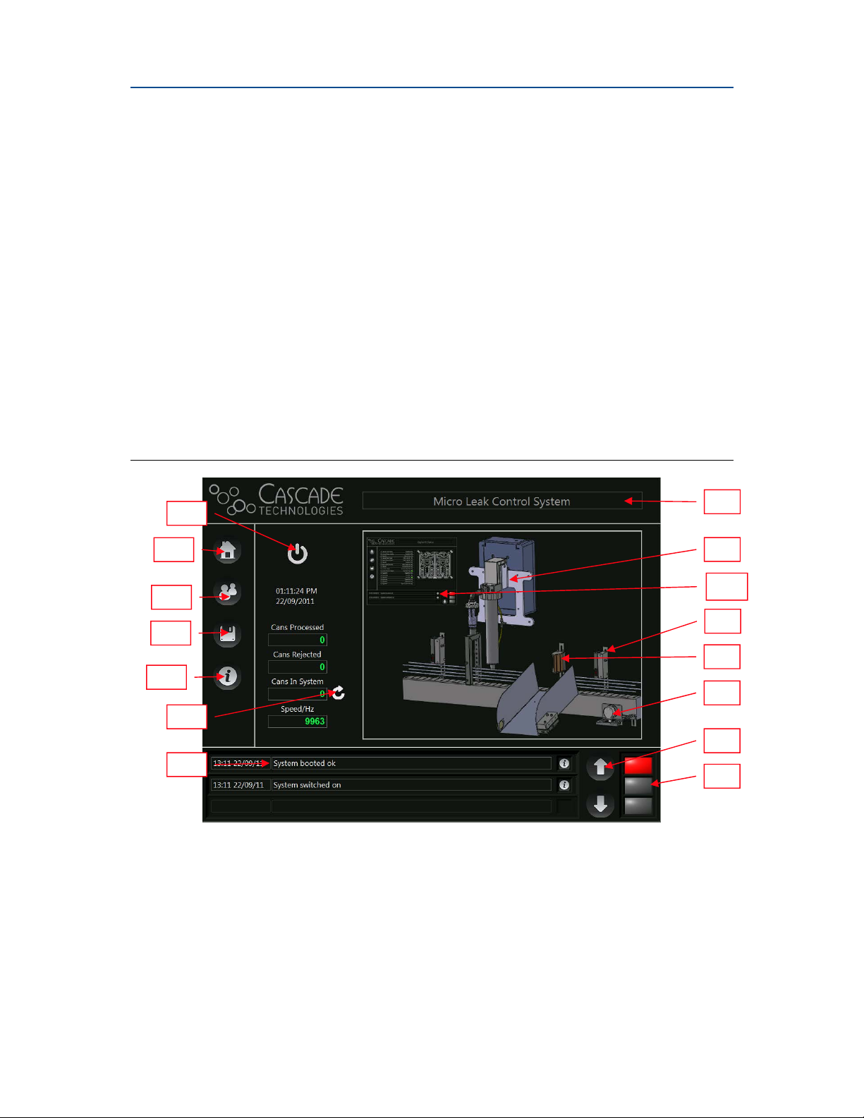
5.1.1 Home screen — aerosol leak detection system
The Home screen is the initial screen displayed by the aerosol leak detection system
after booting.
Figure 5-1 is the Home screen.
Figure 5-1 Control system Home screen
A
B
C
D
E
F
G
A. Powe
B. Home
C. User
D. Programs page
E. Error status page
Operation 15
button: used to turn the system off
safely; generates a prompt to confirm the
switch is off.
button: allows navigation back to this
screen from any screen.
login button: changes the central
section of the screen to the User Login
screen.
button: changes the central
section of the screen to the Programs page.
button: changes the central
section of the screen to the error status
H.
Title bar: displays the title of the current
page.
Main Screen button: changes the center
I.
section of the screen to the main control
page for the leak detector
J.
IO Status Page button changes the center
section of the screen to the IO Status page.
Optical Gates Page button: changes the
L.
center section of the screen to the Optical
Gates page.
M. Rejector Page
section of the screen to the Rejector page.
button: changes the center
H
J
K
L
M
N
O
Page 22

Operation User Manual
r
October 2015 QCL-MAN-CT2211-Aerosol-Leak-Detection-System-Rev F
page.
F. Reset can buffe
the can buffer to 0.
G. Message box: displays messages, warnings,
and errors for the control system.
button: resets the cans in
N. Message box arrows: used to scroll up and
down through the messages in the message
box.
O. Error status indicator: shows the current
error status of the control system.
5.1.2 User Login screen
The operation of the aerosol leak detection system requires that some functionality is
restricted to authorized users only. The different user login options are available
through the User Login screen which is shown in
Figure 5-2 below.
Figure 5-2 User login screen
A
B
A. User Selector: allows the operator to select and log in to the different user levels of the
control system.
B. User Description: describes the access options available to the currently logged in user
level.
C. Password change button: prompts the user to change the current password (not available
for all access levels).
D. Language Selector: allows the user to change the language used for display purposes. The
default language of the system is not changed.
C
D
Operation 16
Page 23

User Manual Operation
E F
QCL-MAN -CT2211-Aerosol-Leak-Detection-System-Rev F October 2015
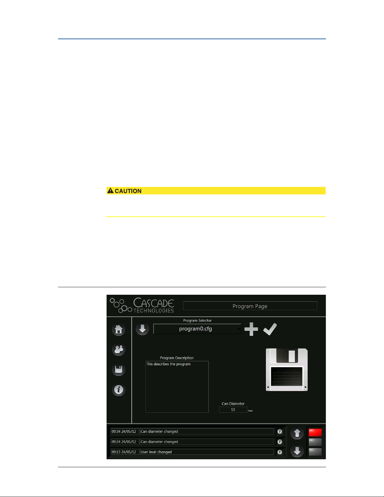
5.1.3 Program Page
The programs used by the control system store the parameters required by the control
system that are variable between different can diameters and products.
See Section 5.4: Control system programs for a description of the creation and use of
programs. Figure 5-3 below shows the Program Page:
Figure 5-3 Program Page screen
A
B
C
D
A. Program Selector: this allows the operator to select from all the programs stored on the
control system.
B. Config backup: this allows the operator to create a backup of the configuration file on an
external USB drive.
C. Program Description: this describes the program and when it should be used. This
information is entered by the user during the program creation process.
D. Add program button: allows the user to add a new program using the current programs
parameters as a starting point.
E. Save changes button: allows the user to save any changes made to the program, this button
is only shown when there are changes to be saved.
F. Can Diameter: the diameter of the container to be used with this program.
Operation 17
Page 24

Operation User Manual
October 2015 QCL-MAN-CT2211-Aerosol-Leak-Detection-System-Rev F
5.1.4 Error Status screen
This screen displays the current state of the control system. It allows the user to reset
any errors once they have cleared. All error signals must be acknowledged by pressing
the reset errors button. Figure 5-4 below shows the Error Status screen:
Figure 5-4 Error Status screen
B
A
A. Error Status: shows the status of all the configured error checks. For all status flags, green is
OK, orange is warning, and red is error.
B. Reset errors button: is used to reset the errors in the control system. If an error persists then
it cannot be reset and will still appear as red or orange on the Error Status list.
Operation 18
Page 25

User Manual Operation
H
QCL-MAN -CT2211-Aerosol-Leak-Detection-System-Rev F October 2015
5.1.5 CT2211 Main Screen
All of the control system parameters relating to the leak detector are displayed on this
page. For all sensor related issues see the Leak Detector manual supplied separately.
Figure 5-5 below shows the Main Screen.
Figure 5-5 CT2211 Main Screen
A
B
C
D
E
F
G
A. Graphs page Button: navigates to the leak detector Graphs page.
B. System Healthy indicator: displays the health status of the leak detector.
C. Laser Healthy indicator: displays the health status of the laser used in the leak detector.
D. Venturi Healthy indicator: displays the health status of the air supply to the Venturi.
E. IP address Indicator: displays the IP address of the leak detector connected to the control
system.
F. Input Gate position: is the position relative to the main input gate of the control system of
the input gate to the leak detector, which is typically located close to the air archway used
to sample gas into the leak detector from the conveyor.
G. Output Gate position: is the position relative to the main input gate of the control system of
the output gate from the leak detector, which is typically located after the air archway used
to sample gas into the leak detector from the conveyor.
H. Purge Frequency: is the time duration (in hours) between the required mirror purge
cleaning function. After this time durationn the system goes into warning for two hours
before going into an error state if the cleaning purge is not performed.
I. Purge Length: is the time (in seconds) that the mirror cleaning purge is activated for.
J. Mirror purge button: activates the purge function, which should not be carried out when
there are cans in the system as the mirror purge function disrupts the normal operation of
the leak detector during the purge duration.
K. CT2211 IN Counter: provides a running count of cans entering the detection zone since last
reset.
L. CT2211 OUT Counter: provides a running count of cans exiting the detection zone since last
reset.
M. CT2211 REJ Counter: provides a running count of cans rejected since last reset.
I
J
K
L
M
Operation 19
Page 26

Operation User Manual
C
October 2015 QCL-MAN-CT2211-Aerosol-Leak-Detection-System-Rev F
5.1.6 CT2211 Graphs Screen
This optional screen allows you to view the laser pulse data and the concentration data
from the leak detector. The data is read from the sensor at a frequency of
approximately 1Hz. The leak detector runs in real time; however, the data displayed on
the graphs is not displayed in real time and is for diagnostic purposes only. Figure 5-6
below shows the CT2211 Graphs Screen.
Figure 5-6 CT2211 Graphs Screen
A
D
B
E
F
A. Laser Pulse Graph: displays a laser pulse from the last second of running.
B. Laser Threshold: is the voltage that the laser pulse must be above to ensure the laser
healthy status signal is OK.
C. Concentration Graph: is the output from the concentration calculations on the Leak
Detector. A rejected can will show as a spike on this graph above the thresholds.
D. Noise: shows the overall noise level of the concentration data. The lower the number the
better.
E. Lower Threshold: in order to reject a can using the lower threshold the leak detector must
see at least two consecutive concentrations above this threshold.
F. Upper Threshold: in order to reject a can using the upper threshold the leak detector must
see at least a single concentration above this threshold.
Operation 20
Page 27

User Manual Operation
QCL-MAN -CT2211-Aerosol-Leak-Detection-System-Rev F October 2015
5.1.7 Digital IO Status screen
This page allows the operator to see in real time the state of any of the digital IO lines
to the control system. For some signals that are rapidly changing, the signal change on
screen may be too quick to observe. Figure 5-7
screen:
Figure 5-7 Digital IO Status screen
A
below shows the Digital IO Status
B
A. Digital inputs: displays the current status of the digital inputs to the control system. Green
is active, and grey is inactive.
B. Digital outputs: displays the current status of the digital outputs from the control system.
Green is active, and grey is inactive.
Operation 21
Page 28

Operation User Manual
E
October 2015 QCL-MAN-CT2211-Aerosol-Leak-Detection-System-Rev F
5.1.8 Optical Gates screen
The Optical Gates screen allows the user to see the output gate position and the bin
full time for the control system.
Figure 5-8 below shows the Optical Gates screen:
Figure 5-8 Optical Gates page
A
B
C
D
F
A. Input Gate Position: displays the position in mm of the input gate of the system. This is
always 0.
B. Output Gate Position: displays the position in mm of the output gate of the system relative
to the input gate.
C. Bin Full Time: is the time in seconds that the reject verification gate must be blocked for the
bin full error to be displayed.
D. Last Output: monitors the canister position as it exits the leak detection system.
E. Position Summary Chart: summarizes any deviations in the expected can position when
exiting the leak detection system.
F. Position Summary Chart Reset: clears the Position summary chart.
Operation 22
Page 29

User Manual Operation
QCL-MAN -CT2211-Aerosol-Leak-Detection-System-Rev F October 2015
5.1.9 Rejector screen
The rejector is used by the control system to remove faulty containers from the
production line. There are a number of different options for the rejector. This manual
assumes that the default air rejector is being used. Figure 5-9 below shows the
Rejector screen:
Figure 5-9 Rejector page
A
D
B
C
A. Rejector Description: describes the rejector in use.
B. Rejector Position: is the position relative to the main input gate of the rejector.
C. Rejector Timing: is the length of time the rejector is active for each faulty container.
D. Rejector Type: shows a picture of the particular rejector in use.
E. Number of Consecutive Rejects: is the number of consecutive canister rejects required to
trigger the Too many consecutive rejects alarm.
F. Check mark: is to apply changes made to Number of Consecutive Rejects and Number of
Repeatable Rejects to the configuration file. If the changes are not stored, they will be reset
to the previously stored values on system reboot.
G. Number of Repeatable Rejects: is the number of canister rejects per 100 canisters required
to trigger the Repeatable Reject Error alarm.
E
F
G
Operation 23
Page 30

Operation User Manual
October 2015 QCL-MAN-CT2211-Aerosol-Leak-Detection-System-Rev F
5.1.10 Line Speed screen
This page shows the line speed of the conveyor.
Figure 5-10 below shows the Line Speed screen.
Figure 5-10 Line Speed screen
C
A
D
B
A. Encoder Description: describes the use of the encoder.
B. Line Speed: is the one second average of the line speed.
C. Encoder Scaling: is the ratio of pulses of the encoder to mm of travel on the production line.
It is used to convert the encoder count from pulses to distance.
D. Encoder Count: is the total number of pulses on the encoder since the control system was
last switched on.
E. Line speed graph: shows the speed of the production line for the last sixty seconds.
E
5.2 Errors
There are a number of errors that the control system monitors for that may occur
during the normal operation of the system. If the error status indicator in the bottom
right hand side of the screen or if the traffic light indicators change from green then
the control system has detected an error. Most errors are easily reset from the Error
Status screen of the control system. The errors that are active show as red lights on the
Error Status screen. The following errors are detectable by the control system:
5.2.1 Overall system healthy
The overall system healthy error checks the system parameters on boot. If this error
occurs, there will be an explanation of the reason in the message box at the bottom of
the screen. The most likely reason for this error is an incorrect parameter in a
configuration file or missing configuration file. There files can be reinstalled with the
assistance of Cascade Technologies Ltd.
Operation 24
Page 31

User Manual Operation
QCL-MAN -CT2211-Aerosol-Leak-Detection-System-Rev F October 2015
5.2.2 Leak detector (CT2211) system healthy
The leak detector provides the control system with a healthy status signal. If this signal
becomes too low, it will trigger this error. See Section 7: Troubleshooting and
Diagnostics for more information on this error.
5.2.3 Leak detector (CT2211) laser healthy
The leak detector provides the control system with a healthy status signal for the laser
pulse. If this signal becomes too low, it triggers this error. See Section 7:
Troubleshooting and Diagnostics for more information on this error.
5.2.4 Can lost
The cans in the system are tracked using a combination of optical gates and a line
encoder. This allows the control system to predict when a particular container should
reach the output gate of the system (assuming it is not rejected). If a can does not
trigger the output gate in a set window, then this error is triggered. The following are
the most likely reasons for this error:
The output gate is positioned incorrectly.
Cans are slipping on the production line.
Someone has removed a can from the line inside the system.
A can in the system has fallen.
The height of the gate output is wrong, causing the gate not to trigger when
cans go through.
The output gate is not working or disconnected.
In order to reset this error all the cans in the system must be removed, and the can
buffer must be reset using the can buffer reset button on the Home screen.
5.2.5 Can found
The cans in the system are tracked using a combination of optical gates and a line
encoder. This allows the control system to predict when a particular container should
reach the output gate of the system (assuming it is not rejected). If there is a trigger on
the output gate that falls outside of the expected window, this error is triggered. The
following are the most likely reasons for this error:
The output gate is positioned incorrectly.
Cans are slipping on the production line.
Someone has added a can after the input gate and before the output gate.
5.2.6 Too many consecutive rejects
If a number of cans above a configurable threshold are rejected in a row, this error is
triggered. In order to reset this error, a good can must be put through the system. This
error may be used as a potential indication of a production fault.
Operation 25
Page 32

Operation User Manual
October 2015 QCL-MAN-CT2211-Aerosol-Leak-Detection-System-Rev F
5.2.7 Reject verification
When the rejector removes a can from the line, the reject verification gate expects to
see a trigger with in a set time after the rejector is activated. If the reject verification
gate does not see this trigger, the reject verification error is triggered. There are a
number of reasons this may occur:
A can has been unsuccessfully rejected.
The reject verification gate is disconnected or not working.
The trigger is taking too long to activate.
5.2.8 Encoder error
The correct operation of the encoder is vital for the control system to function. There is
a range of line speeds that the encoder expects to see (from 0m/s to 1.5m/s). If the
speed of the line is outside of this range, the error will be triggered. The error is also
triggered if the encoder sees that the line is running and the line stop input signal is
low, meaning that the control system expects the line to be stopped.
5.2.9 Air sampling healthy
The Cascade pressure switch is used to monitor the air supply to the system. If the air
supply is interrupted, the pressure switch will activate this error.
5.2.10 Bin full
As the number of cans removed from the line increases, the reject bin begins to fill.
The reject verification gate is used to detect when the bin is overflowing and trigger
the bin full error.
5.2.11 Mirror purge warning
The leak detector requires a mirror purge cleaning at regular intervals to maintain the
performance of the sensor. The control system has a timer that is used to ensure that
this cleaning purge is performed. Once the timer reaches 0, the warning light is
activated for two hours to remind the user to operate the purge.
5.2.12 Mirror purge error
The leak detector requires a mirror purge cleaning at regular intervals to maintain the
performance of the sensor. The control system has a timer that is used to ensure that
this cleaning purge is performed. Once the mirror purge warning has been active for
two hours, the mirror purge error is triggered, forcing you to purge the mirrors before
the system continues.
In addition to the errors listed above that the control system can detect, there is a
hardware watch dog on the system. If the system crashes, the watch dog will cause the
system to become unhealthy, and the production line PLC can read the output from
this watch dog to ensure that the system remains healthy.
In order to reset any of the errors above, press the Reset errors button on the Error
Status page. This clears any errors that are no longer affecting the system. If any errors
persist, the error status indicator will not turn green, and the reason for the continued
error should be investigated.
Operation 26
Page 33

User Manual Operation
QCL-MAN -CT2211-Aerosol-Leak-Detection-System-Rev F October 2015
5.2.13 Repeatable reject error
The repeatable reject error reports when the number of rejects per hundred canisters
exceeds a configurable threshold. This threshold is set on the Rejector screen and can
be saved to the configuration file. This error may be used as an indication of a
production fault.
5.2.14 Compressed air error
The compressed air error reports when insufficient pressure on the
Venturi/reject/purge air is detected. Insufficient air pressure results in decreased
performance of the CT2211 aerosol leak detection system.
5.2.15 Error flags 14/15
These error flags are currently unassigned.
5.3 Line PLC communication
The aerosol leak detection system communicates to the line PLC via digital IO lines.
The input and output lines to the control system are 24 VDC. The connections from
the control system to the line PLC are made inside the console as shown below:
Figure 5-11 PLC connections
PLC
connections
Operation 27
Page 34

Operation User Manual
October 2015 QCL-MAN-CT2211-Aerosol-Leak-Detection-System-Rev F
Table 5-1 IO lines
Terminal
number :
20 Linestop Input
21 Shutdown system Input
22 Spare Input N/A
23 Spare Input N/A
24 Spare Input N/A
25 Return Input N/A
26 Linestop 1 Output
27 Linestop 2 Output
28 Heartbeat Signal Output
29 Reject Pulse Count Output
30 Not Available Output N/A
31 Return Output N/A
Inputs to Control System : Terminals 20 — 24 (+24V), Return Terminal 25 (0V)
Outputs From Control System : Terminals 26 — 30 (+24V), Return Terminal 31 (0V)
The wiring numbers for each of the input and output lines can be found in the system
wiring diagram.
Line description
System input/output See Section
number :
5.3.1
5.3.2
5.3.3
5.3.3
5.3.4
5.3.5
Each of the individual IO lines is described below:
5.3.1 Linestop (in)
A positive Linestop voltage input signal from the conveyer to the Control System
indicates the conveyer is working within its operational parameters. A 0.0V signals the
line is stopped.
5.3.2 System shutdown signal (in)
The system shutdown signal allows the control system to be deactivated remotely. If
the signal is high, the control system continues to function. If the signal is low, the
control system switches off.
5.3.3 Linestop 1 and linestop 2 (out)
The control system provides two output signals to stop the production line if there are
errors on the system. The two outputs can be configured to trigger for different errors.
If the linestop signals are high, the system is healthy; if either or both of the linestop
signals are low, the production line should be stopped.
5.3.4 Heartbeat signal (out)
The heartbeat signal is the hardware watchdog output. If the signal is high, then the
system is running normally. If the system is low, the watchdog has detected an error,
and the system should be reset.
5.3.5 Reject counter pulse (out)
For each can removed from the production line by the rejector, a 100ms counter pulse
is sent on this output line. This allows the line PLC to know how many cans have been
rejected by the control system.
Operation 28
Page 35
User Manual Operation
QCL-MAN -CT2211-Aerosol-Leak-Detection-System-Rev F October 2015
5.4 Control system programs
The aerosol leak detection system loads parameters from a number of different
sources. One of those sources is the program file. The parameters loaded from the
program file are:
1. Output gate position
2. Cascade input gate position
3. Cascade output gate position
4. Rejector position
5. Can diameter
6. Bin full time
7. Maximum consecutive rejects — line stoppable
8. Maximum repeatable rejects — line stoppable
Use of an incorrect program may lead to degraded performance of the control system,
and the wrong cans may be rejected.
Use the Program Page | Program Selector to change or load a Control System
program. A login security level of Power User or higher is required for an operator to
save changes to the program.
The save changes button applies the changes to the currently loaded program.
The Program Description provides detailed information about the currently loaded
Control System program.
Figure 5-12 Program Page
Operation 29
Page 36

Operation User Manual
October 2015 QCL-MAN-CT2211-Aerosol-Leak-Detection-System-Rev F
The different programs allow the user to customize the operation of the control systm
for different can types and diameters. The program can also be backed up by selecting
the down arrow to the left of the Program Selector as seen in Figure 5-12 Program
Page.
5.4.1 Add programs
If you have a Power user or higher security level, you can add extra programs (up to a
maximum of twenty-five). To add a program, press the Add programs button on the
Program Page. Figure 5-13 below shows the Add programs screen. There is a
description of the program on the Add programs screen that helps inform you about
your selection.
Figure 5-13 Add programs screen
The values on the right of the Add Programs screen come from the currently loaded
program. You can enter the program description with the on screen keyboard, which
loads when the Program Description box is touched.
The other parameters on the right hand of the screen can be edited in the main control
system. When you have finished making your changes, press the Save button.
Operation 30
Page 37

User Manual Maintenance
QCL-MAN -CT2211-Aerosol-Leak-Detection-System-Rev F October 2015
6 Maintenance
The aerosol leak detection system is inherently reliable, reducing the requirement for
routine maintenance. This section provides information on the schedule of
maintenance to be performed by the user in order to ensure the reliable performance
of the system.
For all maintenance inside of the control console, the system must be powered off
using the shutdown procedure detailed earlier. There are potentially dangerous
voltages inside the console.
6.1 Schedule
The maintenance activities and their related frequencies are shown below:
6.1.1 Daily
These are the activities that should be performed once per day:
Perform an air purge of the leak detector’s mirrors.
Verify the leak detection performance of the sensor by passing a leaking can
through the sensor (or equivalent test technique).
6.1.2 Weekly
These are the activities that should be performed once per week:
Inspect and clean the optical gates and reflectors.
Check the pressure settings on the filter/regulators.
Inspect the rejector and ensure it is operating correctly.
Inspect the encoder to ensure the coupling to the line is solid.
6.1.3 Monthly
These are the activities that should be performed once per month:
Inspect and clean the air arch filter.
Verify that the compressed air supply to the leak detector is within the levels
specified in Section 1.6: Detailed system specification.
This represents an advanced operation of the leak detector and should only be
performed by suitably trained personnel.
In order to ensure that the aerosol leak detection system is reliable over the long term,
an annual service is recommended. This service should be carried out by a Cascade
engineer or a Cascade-trained service engineer.
6.2 Analysis system
The leak detector system is inherently tolerant to high levels of contamination without
a reduction in performance. The comprehensive filtering undertaken within the air
arch ensures that there should be no need to clean any part of the leak detector within
the lifetime of the product.
Maintenance 31
Page 38

Maintenance User Manual
October 2015 QCL-MAN-CT2211-Aerosol-Leak-Detection-System-Rev F
6.3 Venturi
The Venturi should require no maintenance other than periodic exterior cleaning to
remove surface dust.
6.4 Replacement parts
The following parts are available from Cascade as replacement parts for the leak
detection system:
Table 6-1 Aerosol leak detection system replacement parts list
Part description Zone
Touchscreen P-5000-0578 Yes
Control PC and software (DAC
and controls)
I/O board P-5000-0580 Yes
Fan module P-5000-0581 Yes
Optical gate Zone 2 P-5000-0328a Yes
Optical reflector Zone 2 P-5000-0328b Yes
Encoder Zone 2 P-5000-0327 Yes
Sample flow filters Zone 2 M-1000-1840 Yes
Sample flow filter housing Zone 2 P-5000-0060 Yes
Venturi Zone 2 P-5000-0117 Yes
Pressure switch Zone 2 P-5000-0615 Yes
Power supply 12 V Zone 2 P-5000-0331 Yes
Power supply 24 V Zone 2
Leak generator valve
Filter/regulator Zone 2
Solenoid valve Zone 2
Blower Zone 2
Differential pressure switch
40 micron filter Zone 2
0.01 micron filter Zone 2
Lens cleaning tissue (Pack of 5) P-5000-0613 Yes
Fully assembled pneumatic plate Zone 2 M-3000-0609 Yes
Carbon filter sleeves (enclosure
purge)
Precision optical cleaner
P-5000-0579 No
Zone 2
Zone 2
Zone 2 P-5000-0680 Yes
Part number
P-5000-0392
P-5000-0587
P-5000-0560
P-5000-0329
P-5000-0389
P-5000-0588
P-5000-0589
P-5000-0590
P-5000-0681
User replaceable?
Yes
Yes
Yes
Yes
Yes
Yes
Yes
Yes
Yes
Maintenance 32
Page 39

User Manual Troubleshooting and Diagnostics
QCL-MAN -CT2211-Aerosol-Leak-Detection-System-Rev F October 2015
7 Troubleshooting and Diagnostics
The aerosol leak detection system is designed to run unattended and to recover from
system issues where possible. This chapter is designed to assist you in the
identification and solution of potential problems. If in doubt, contact Cascade
Technologies Ltd for clarification on solutions before continuing.
7.1 Warning and error messages
There are a number of warning and error messages that the system can generate,
which will be displayed in the message box at the bottom of the screen.
Table 7-1 Possible problems and solutions
Problem Symptom Possible causes
Plots are not
updated on the leak
detection system
Graphs screen.
Cannot update
system settings
System does not
boot up when
powered
The laser pulse graph
and concentration
graph are not displayed
or do not update on the
leak detector Graphs
screen.
It is not possible to
change any of the
parameters, such as
output gate position.
The control system
does not power on.
The network connection is
not established. The leak
detection system network
cable must be connected
to the network switch in
the control console, and
the network cable to the
PC must be installed into
the same switch.
The leak detection system
is not powered. See the
leak detection systems
manual for trouble
shooting.
You are logged in as User.
In order to make changes
to the settings, you must
be logged in as Power User
or above.
The touch screen is not
working.
The isolation switch on the
front of the control system
is set to OFF.
Solutions
Ensure that the
indicator lights are
flashing on the
network switch for
both cables. See
Figure 7-1.
Check the LED on the
12V PSU in the
control console. See
Figure 7-2.
Log in as a Power User
or above.
Contact the factory.
Turn the isolation
switch to the ON
position.
The circuit breaker on the
inside of the control system
is tripped.
The system was not
powered off for long
enough. The isolation
switch must be off for a
minimum of thirty seconds
prior to booting the system.
Set the circuit breaker
to the ON position.
See Figure 7-3.
Turn the system off.
Wait thirty seconds,
and then turn the
system back on.
Troubleshooting and Diagnostics 33
Page 40

Troubleshooting and Diagnostics User Manual
October 2015 QCL-MAN-CT2211-Aerosol-Leak-Detection-System-Rev F
Figure 7-1 Network status
Network
status lamps
Figure 7-2 12V PSU status
12V PSU status
lamp
Troubleshooting and Diagnostics 34
Page 41

User Manual Troubleshooting and Diagnostics
QCL-MAN -CT2211-Aerosol-Leak-Detection-System-Rev F October 2015
Figure 7-3 Circuit breaker
Circuit
breaker
Troubleshooting and Diagnostics 35
Page 42

QCL-MAN-2211-Aerosol-Leak-Detection-System
Revision F
2015
EmersonProcess.com/GasAnalysis
AnalyticExpert.com
youtube.com/user/RosemountAnalytical
HEADQUARTERS
Emerson Process Management
Glendevon House
Castle Business Park,
Stirling FK9 4TZ UK
T +44 (0) 1786 447721
F +44 (0) 1786 475822
qcl.csc@emerson.com
©2015 Emerson Process Management. All rights reser ved.
The Emerson logo is a trademark and service mark of Emerson Electric Co. All other marks are property of
their respective owners.
The contents of this publication are presented for information purposes only, and, while effort has been made
to ensure their accuracy, they are not to be construed as warranties or guarantees, express or implied,
regarding the products or services described herein or their use or applicability. All sales are governed by our
terms and conditions, which are available on request. We reserve the right to modify or improve the designs
or specifications of our products at any time without notice.
twitter.com/Rosemount_News
facebook.com/Rosemount
 Loading...