

Page 1

Instruction Manual
748451-B
March 2002
Model CAT7
Thermal Conductivity Analyzer
http://www.processanalytic.com
Page 2

ESSENTIAL INSTRUCTIONS
READ THIS PAGE BEFORE PROCEEDING!
Rosemount Analytical designs, manufactures and tests its products to meet many national and
international standards. Because these instruments are sophisticated technical products, you
MUST properly install, use, and maintain them to ensure they continue to operate within their
normal specifications. The following instructions MUST be adhered to and integrated into your
safety program when installing, using, and maintaining Rosemount Analytical products. Failure to
follow the proper instructions may cause any one of the following situations to occur: Loss of life;
personal injury; property damage; damage to this instrument; and warranty invalidation.
• Read all instructions prior to installing, operating, and servicing the product.
• If you do not understand any of the instructions, contact your Rosemount Analytical repre-
sentative for clarification.
• Follow all warnings, cautions, and instructions marked on and supplied with the product.
• Inform and educate your personnel in the proper installation, operation, and mainte-
nance of the product.
• Install your equipment as specified in the Installation Instructions of the appropriate In-
struction Manual and per applicable local and national codes. Connect all products to the
proper electrical and pressure sources.
• To ensure proper performance, use qualified personnel to install, operate, update, program,
and maintain the product.
• When replacement parts are required, ensure that qualified people use replacement parts
specified by Rosemount. Unauthorized parts and procedures can affect the product’s performance, place the safe operation of your process at risk, and VOID YOUR WARRANTY.
Look-alike substitutions may result in fire, electrical hazards, or improper operation.
• Ensure that all equipment doors are closed and protective covers are in place, except
when maintenance is being performed by qualified persons, to prevent electrical shock
and personal injury.
The information contained in this document is subject to change without notice.
Teflon® is a registered trademark of E.I. duPont de Nemours and Co., Inc.
SNOOP® is a registered trademark of NUPRO Co.
Emerson Process Management
Rosemount Analytical Inc.
Process Analytic Division
1201 N. Main St.
Orrville, OH 44667-0901
T (330) 682-9010
F (330) 684-4434
e-mail: gas.csc@EmersonProcess.com
http://www.processanalytic.com
Page 3

Model CAT7
PREFACE...........................................................................................................................................1
Definitions ...........................................................................................................................................1
safety Summary..................................................................................................................................2
General Precautions For Handling And Storing High Pressure Gas Cylinders .................................4
Documentation....................................................................................................................................5
Compliances .......................................................................................................................................5
1.0 DESCRIPTION AND SPECIFICATIONS..............................................................................1-1
1-1 Analyzer Module....................................................................................................................1-1
1-2 Thermal Conductivity Cell......................................................................................................1-1
1-3 Electronic Circuitry.................................................................................................................1-4
1-4 Gas Selector Panel................................................................................................................1-4
1-5 Specifications ........................................................................................................................1-5
Instruction Manual
748451-B
March 2002
TABLE OF CONTENTS
2.0 INSTALLATION ....................................................................................................................2-1
2-1 Site Preparation.....................................................................................................................2-1
2-2 Customer Electrical Connections ..........................................................................................2-1
2-3 Flow Diagrams.......................................................................................................................2-1
2-4 Location and Mounting ..........................................................................................................2-1
a. Location...........................................................................................................................2-1
b. Mounting .........................................................................................................................2-1
2-5 Unpacking..............................................................................................................................2-3
2-6 Gas Requirements.................................................................................................................2-3
2-7 Calibration Gas Requirements ..............................................................................................2-3
a. Sample Gas Composition ...............................................................................................2-3
2-8 Suppressed-Zero Ranges .....................................................................................................2-3
2-9 Leak Check............................................................................................................................2-3
2-10 Gas Connections ...................................................................................................................2-4
2-11 Recorder Output Selection and Cable Connections .............................................................2-8
a. Standard (Non-linearized) Voltage Output......................................................................2-8
b. Linearized Voltage Output (Optional)..............................................................................2-8
c. Isolated 4 to 20 mA Current Output (Optional) ...............................................................2-8
2-12 Alarms (Optional)...................................................................................................................2-10
2-13 Linearized Voltage, Two Ranges (Optional)..........................................................................2-12
2-14 Linearized Voltage and Isolated 4 to 20 mA Current Output (Optional)................................2-12
2-15 Electrical Power Connections................................................................................................2-13
3.0 OPERATION .........................................................................................................................3-1
3-1 Analyzer Controls and Adjustments ......................................................................................3-1
3-2 Gas Selector Panel Controls .................................................................................................3-1
3-3 Startup Procedure .................................................................................................................3-1
3-4 Calibration..............................................................................................................................3-2
Rosemount Analytical Inc. A Division of Emerson Process Management Contents i
Page 4

Instruction Manual
748451-B
March 2002
4.0 THEORY................................................................................................................................4-1
4-1 Thermal Conductivity Cell and Associated Bridge Adjustments ...........................................4-1
4-2 Master Board .........................................................................................................................4-1
a. Functions Associated with AR1 ......................................................................................4-1
b. Coarse zero and zero-suppression.................................................................................4-2
c. Functions Associated with AR2 ......................................................................................4-2
d. Meter ...............................................................................................................................4-2
e. Output Selection Switch S1 ............................................................................................4-2
4-3 Voltage Output Linearizer Board Option ...............................................................................4-2
4-4 Isolated 4 to 20 mA Current Output Board Option ................................................................4-4
4-5 Bridge Power Supply .............................................................................................................4-4
4-6 ±15 Volt Power Supply ..........................................................................................................4-4
4-7 Detector Blocks .....................................................................................................................4-4
4-8 Case Temperature Controller Assembly ...............................................................................4-4
4-9 Dual Alarms Option ...............................................................................................................4-5
5.0 SERVICE AND MAINTENANCE ..........................................................................................5-1
5-1 Thermal Conductivity Cell......................................................................................................5-1
5-2 Electronic Circuitry.................................................................................................................5-4
a. Amplifier Zero Adjustments.............................................................................................5-4
b. Bridge Balance and Range Sensitivity Adjustments.......................................................5-4
c. Case Temperature Controller .........................................................................................5-5
d. Dual Alarm Module (Optional).........................................................................................5-5
5-3 Suppressed Zero Adjustment................................................................................................5-5
Model CAT7
6.0 REPLACEMENT PARTS ......................................................................................................6-1
6-1 Matrix .....................................................................................................................................6-1
6-2 Circuit Board Replacement Policy .........................................................................................6-3
6-3 Replacement Parts ................................................................................................................6-4
7.0 RETURN OF MATERIAL ......................................................................................................7-1
7-1 Return Of Material .................................................................................................................7-1
7-2 Customer Service ..................................................................................................................7-1
7-3 Training..................................................................................................................................7-1
ii Contents Rosemount Analytical Inc. A Division of Emerson Process Management
Page 5

Model CAT7
Figure 1-1. CAT7 Controls, Adjustments, Ports .......................................................................... 1-2
Figure 1-2. Fuse Location............................................................................................................ 1-2
Figure 1-3. CAT7 – Exploded View ............................................................................................. 1-3
Figure 1-4. Typical Gas Selector Panel....................................................................................... 1-4
Figure 2-1. Gas Selector Panel for Thermal Conductivity Cell with Sealed-In Reference Gas .. 2-1
Figure 2-2. Gas Selector Panel for Thermal Conductivity Cell Using Flowing Reference Gas .. 2-2
Figure 2-3. Gas Connections – Bottom View of Analyzer ........................................................... 2-4
Figure 2-4. Connection of Analyzer Using Sealed-In Reference Gas to Associated Gas .......... 2-5
Figure 2-5. Connection of Analyzer Using Flowing Reference Gas to Associated Gas Selector
Figure 2-6. Intrinsic Safety Box ................................................................................................... 2-7
Figure 2-7. Intrinsic Safety Box Interconnect .............................................................................. 2-7
Figure 2-8. Master Board............................................................................................................. 2-9
Figure 2-9. Alarm Adjustments ..................................................................................................2-10
Figure 2-10. Typical Alarm Settings .......................................................................................... 2-11
Figure 2-11. Case Heater Temperature Control Board............................................................. 2-13
Figure 4-1. Thermal Conductivity Cell ......................................................................................... 4-3
Instruction Manual
748451-B
March 2002
LIST OF ILLUSTRATIONS
Panel...................................................................................................................... 2-6
LIST OF TABLES
Table 1-1. Available Gas Selector Panels................................................................................... 1-5
Table 4-1. Range Switch Connections ........................................................................................ 4-2
DRAWINGS
613561 Schematic Diagram, Bridge Power Supply - Regulated 5 to 15V
619710 Schematic Diagram, 15V Power Supply
624003 Schematic Diagram, Temperature Controller
652813 Schematic Diagram, Isolated Current Output
652863 Schematic Diagram, Linearizer Board
654616 Schematic Diagram, Master Board
661200 Assembly Instructions, CAT7
661203 Assembly, Chassis
661318 Installation Drawing, CAT7
661540 Assembly, Temperature Control
661541 Assembly, Meter
661562 Wiring Diagram, CAT7
(LOCATED IN REAR OF MANUAL)
Rosemount Analytical Inc. A Division of Emerson Process Management Contents iii
Page 6

Instruction Manual
748451-B
March 2002
Model CAT7
iv Contents Rosemount Analytical Inc. A Division of Emerson Process Management
Page 7

Instruction Manual
Model CAT7
PREFACE
The purpose of this manual is to provide information concerning the components,
functions, installation and maintenance of the CAT7 Thermal Conductivity Analyzer.
Some sections may describe equipment not used in your configuration. The user should
become thoroughly familiar with the operation of this module before operating it. Read
this instruction manual completely.
DEFINITIONS
The following definitions apply to DANGERS, WARNINGS, CAUTIONS and NOTES found throughout
this publication.
DANGER .
748451-B
March 2002
Highlights the presence of a hazard which will cause severe personal injury, death, or substantial
property damage if the warning is ignored.
WARNING .
Highlights an operation or maintenance procedure, practice, condition, statement, etc. If not
strictly observed, could result in injury, death, or long-term health hazards of personnel.
CAUTION.
Highlights an operation or maintenance procedure, practice, condition, statement, etc. If not
strictly observed, could result in damage to or destruction of equipment, or loss of effectiveness.
NOTE
Highlights an essential operating procedure,
condition or statement.
Rosemount Analytical Inc. A Division of Emerson Process Management Preface P-1
Page 8

Instruction Manual
748451-B
March 2002
Model CAT7
SAFETY SUMMARY
To avoid explosion, loss of life, personal injury and damage to this equipment and on-site property, all personnel authorized to install, operate and service the Model CAT7 Thermal Conductivity Analyzer should be
thoroughly familiar with and strictly follow the instructions in this manual. Save these instructions.
If this equipment is used in a manner not specified in these instructions, protective systems may be
impaired.
AUTHORIZED PERSONNEL
To avoid explosion, loss of life, personal injury and damage to this equipment and on-site
property, all personnel authorized to install, operate and service the this equipment should be
thoroughly familiar with and strictly follow the instructions in this manual. SAVE THESE INSTRUCTIONS.
DANGER.
ELECTRICAL SHOCK HAZARD
Do not operate without doors and covers secure. Servicing requires access to live parts which can
cause death or serious injury. Refer servicing to qualified personnel.
For safety and proper performance this instrument must be connected to a properly grounded
three-wire source of power.
NOTE
Before supplying electrical power to the analyzer, remove power to the bridge by disconnecting the
red lead from the bridge to TB1-1 or TB1-2 (depending on the bridge polarity). See drawing 661562.
To safeguard against filament damage, this lead should remain disconnected until proper gas flow
has been established.
DANGER
EXPLOSION HAZARD
Do not operate the Model CAT7 Explosion-Proof Analyzer without the lens cover in place and completely secured, unless location have been determined to be non-hazardous.
P-2 Preface Rosemount Analytical Inc. A Division of Emerson Process Management
Page 9

Instruction Manual
Model CAT7
DANGER
EXPLOSION HAZARD
This analyzer is of a type capable of analysis of sample gases which may be flammable. If used for
analysis of such gases, the instruments explosion-proof enclosure must be suitable for the gas.
If explosive gases are introduced into this analyzer, the sample containment system must be carefully leak-checked upon installation and before initial startup, during routine maintenance and any
time the integrity of the sample containment system is broken, to ensure the system is in leak-proof
condition. Leak-check instructions are provided in Section 2-9.
Internal leaks resulting from failure to observe these precautions could result in an explosion
causing death, personal injury or property damage.
WARNING .
PARTS INTEGRITY
Tampering or unauthorized substitution of components may adversely affect safety of this product.
Use only factory documented components for repair.
748451-B
March 2002
WARNING.
HIGH PRESSURE GAS CYLINDERS
This instrument requires periodic calibration with a known standard gas. See also General Precautions for Handling and Storing High Pressure Gas Cylinders, page P-4.
Rosemount Analytical Inc. A Division of Emerson Process Management Preface P-3
Page 10

Instruction Manual
748451-B
March 2002
Model CAT7
GENERAL PRECAUTIONS FOR HANDLING AND STORING HIGH
PRESSURE GAS CYLINDERS
Edited from selected paragraphs of the Compressed Gas Association's "Handbook of Compressed
Gases" published in 1981
Compressed Gas Association
1235 Jefferson Davis Highway
Arlington, Virginia 22202
Used by Permission
1. Never drop cylinders or permit them to strike each other violently.
2. Cylinders may be stored in the open, but in such cases, should be protected against extremes of weather
and, to prevent rusting, from the dampness of the ground. Cylinders should be stored in the shade when located in areas where extreme temperatures are prevalent.
3. The valve protection cap should be left on each cylinder until it has been secured against a wall or bench, or
placed in a cylinder stand, and is ready to be used.
4. Avoid dragging, rolling, or sliding cylinders, even for a short distance; they should be moved by using a suitable hand-truck.
5. Never tamper with safety devices in valves or cylinders.
6. Do not store full and empty cylinders together. Serious suckback can occur when an empty cylinder is attached to a pressurized system.
7. No part of cylinder should be subjected to a temperature higher than 125
permitted to come in contact with any part of a compressed gas cylinder.
8. Do not place cylinders where they may become part of an electric circuit. When electric arc welding, precautions must be taken to prevent striking an arc against the cylinder.
°
F (52°C). A flame should never be
P-4 Preface Rosemount Analytical Inc. A Division of Emerson Process Management
Page 11

Instruction Manual
Model CAT7
DOCUMENTATION
The following CAT7 Thermal Conductivity Analyzer instruction materials are available. Contact Customer
Service or the local representative to order.
748451 Instruction Manual (this document)
COMPLIANCES
This product may carry approvals from several certifying agencies. The certification marks appear on the
product name-rating plate.
Area Classifications:
USA
Class I Zone 1
AEx d e m IIB + H
2
T4
748451-B
March 2002
Canada
Ex d e m IIB + H
European Union
ATEX, Category 2, Zone 1, IIB + H
USA/Canada
Certified by Canadian Standards Association, an OSHA Nationally Recognized Testing Laboratory (NRTL) for USA and Canada.
European Union
Conforms with the provisions of the EMC Directive 89/336/EEC, Low Voltage Directive 73/23/EEC, Potentially Explosive Atmospheres Directive
94/9/EC, including amendments by the CE marking Directive 93/68/EEC.
EC type Examination Certificate, LCIE 00 ATEX 6009 X.
Rosemount Analytical has satisfied all obligations from the European Legislation to harmonize the product requirements in Europe.
Australia/New Zealand
T4
2
T4
2
®
0081
EEx d e m II B (+H2) T4
LCIE 00 ATEX 6009 X
II 2 G
Conforms with Electromagnetic Compatibility – Generic Emission standard
and AS/NZS 4251.1 – 1994 Part 1 – Residential, commercial, and light industrial.
Complies with the NAMUR RECOMMENDATION, Electromagnetic Compatibility (EMC) issue 1998.
Rosemount Analytical Inc. A Division of Emerson Process Management Preface P-5
NAMUR
N96
Page 12

Instruction Manual
748451-B
March 2002
Model CAT7
P-6 Preface Rosemount Analytical Inc. A Division of Emerson Process Management
Page 13

Model CAT7
Instruction Manual
748451-B
March 2002
SECTION 1
DESCRIPTION AND SPECIFICATIONS
The Model CAT7 Thermal Conductivity Analyzer is
designed to continuously measure the concentration of
a single component of interest in a flowing gas mixture. The measurement is based on the different
thermal conductivity's of the individual components of
the sample stream. The method is especially well
suited to analysis of two-component sample streams.
However, analysis of multi-component streams is possible if the various components of the background gas
occur in relatively constant ratio, or have similar thermal conductivity's.
Each Model CAT7 Analyzer is factory-assembled, as
ordered, for determination of a specified component,
with specified range of concentration, contained in a
background component or background mixture of
known composition. Typical examples include: 0 to
100 % hydrogen in nitrogen; 20 to 50 % helium in
methane; and 0% to 3% carbon dioxide in air. If so
ordered, the instrument is provided with two or three
ranges; selectable via a side-panel switch. Information specific to the individual instrument is provided in
the data sheet inserted in the back of this instruction
manual.
A Model CAT7 Analyzer consists of an analyzer module, Section 1-1, and, if ordered, an accessory gas
selector panel, Section 1-4.
1-2 THERMAL CONDUCTIVITY CELL
The thermal conductivity cell is a metal
block with separate passages for the sample and reference gases. In all applications,
the sample passage receives a continuous
flow of sample gas. Depending on the application, the reference passage may receive a continuous flow of reference gas, or
may have the reference gas sealed within.
The sample passage contains a pair of
temperature-sensitive resistive filaments.
The reference passage contains a similar
pair. Electrically, the filaments are connected as legs of a Wheatstone bridge. An
internal voltage-regulated power supply is
connected via a 20-ohm dropping resistor,
to the bridge.
With the power supply output adjusted to
provide an appropriate voltage across the
bridge, an electric current flows through the
filaments, heating them and thus increasing
their electrical resistance. The
heat-dissipation rate for each filament depends on the thermal conductivity of the
surrounding gas.
1-1 ANALYZER MODULE
The analyzer module is supplied in an explosion-proof enclosure suitable for installation in
hazardous locations classified as Zone 1,
Groups II B (+H
Group II B (+H
Rosemount Analytical Inc. A Division of Emerson Process Management Description and Specifications 1-1
), T4, Category 2, Zone 1,
2
), T4.
2
Initially, with suitable downscale calibration
gas flowing through the sample passage
(and also through the reference passage if
of the flow-through configuration), the
bridge is balanced. Thereafter, any change
in the relative proportions of the components passing through the sample passage
changes the thermal conductivity of the gas
mixture, causing a temperature differential
between sample and reference filaments.
The resultant change in filament resistance
unbalances the bridge, applying a signal to
the electronic circuitry (Section 1-3).
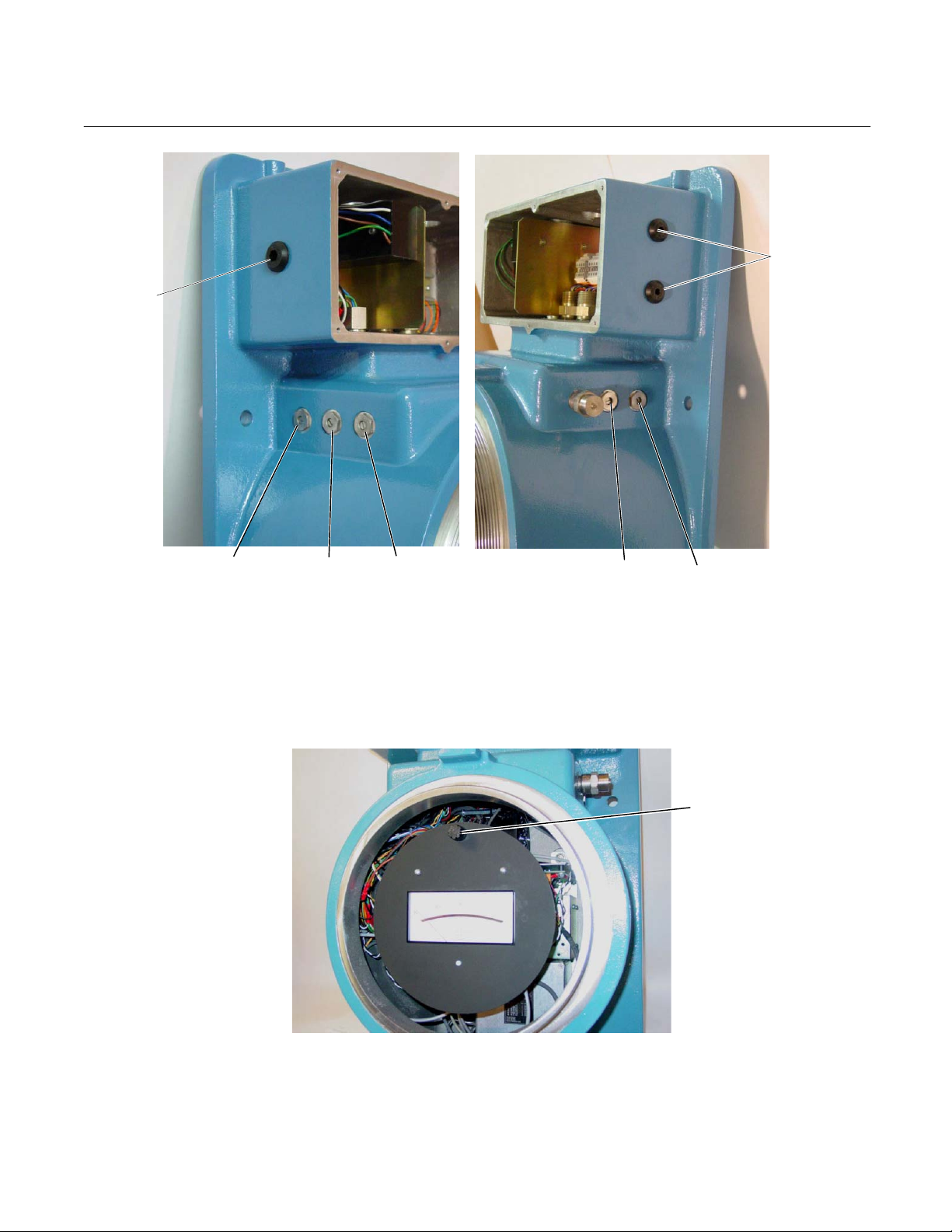
Page 14
Instruction Manual
Adj
748451-B
March 2002
AC Power
Port
Model CAT7
Signal Output,
Alarm Ports
Alarm
Alarm
Figure 1-1. CAT7 Controls, Adjustments, Ports
Range Select
Zero
ust
Span
Fuse
Figure 1-2. Fuse Location
1-2 Description and Specifications Rosemount Analytical Inc. A Division of Emerson Process Management
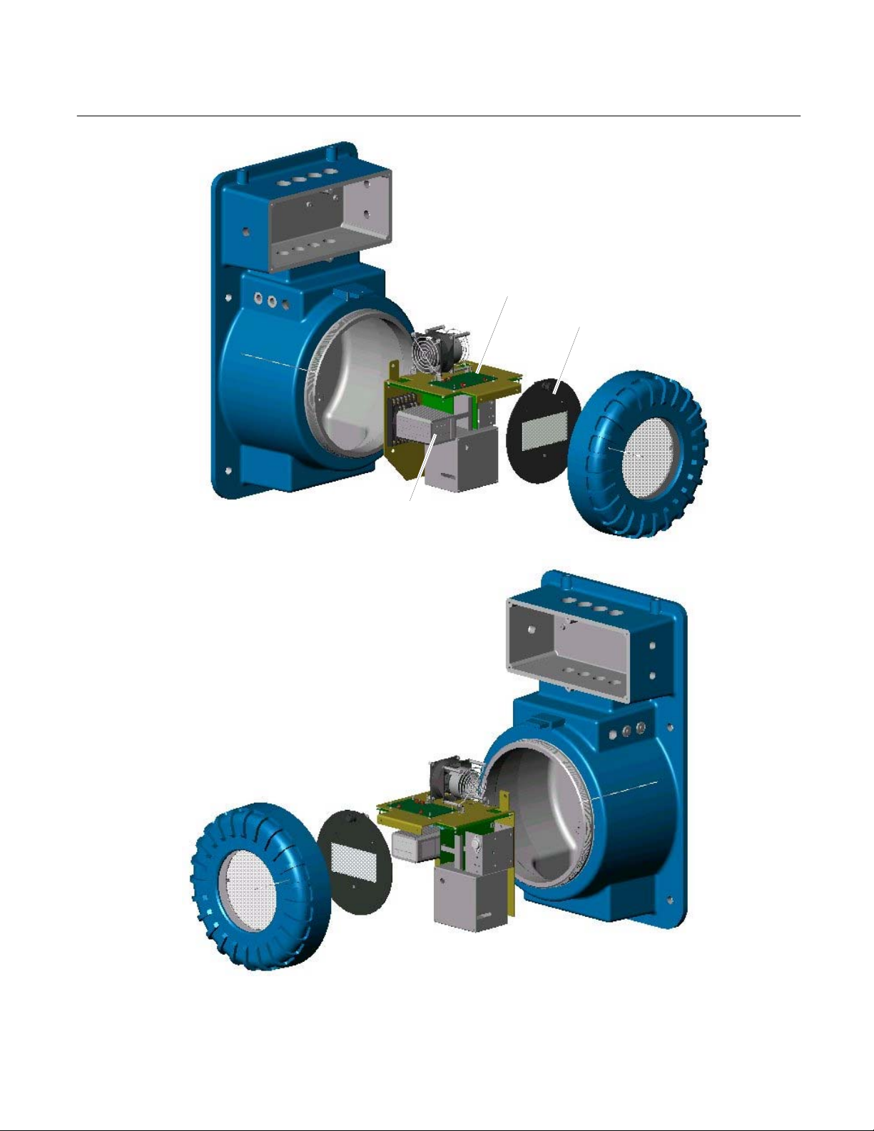
Page 15
Model CAT7
Instruction Manual
748451-B
March 2002
Chassis Assembly
Meter Assembly
Alarm Module
Figure 1-3. CAT7 – Exploded View
Rosemount Analytical Inc. A Division of Emerson Process Management Description and Specifications 1-3
Page 16

Instruction Manual
1
1
748451-B
March 2002
Model CAT7
1-3 ELECTRONIC CIRCUITRY
The analyzer module contains solid-state circuitry that conditions the bridge-imbalance
signal as required to provide readout on the
meter. In addition, a field-selectable output
for a voltage-type recorder is provided as
standard. A field-selectable output of 4 to 20
mA for a current-actuated recorder or other
device is obtainable through use of an optional plug-in circuit board. A calibration
curve can be used to convert meter or recorder readings into concentration values.
Typical calibration curves are supplied for
standard ranges. Calibration curves for special ranges are available as options.
To avoid use of a calibration curve in an application where it would otherwise be required,
the analyzer may be equipped with an optional linearizer board. If so, the linearizer is
factory set for a given range only, and is not
usable on another range. Note that a linearizer is usable only if non-linearity at mid-
scale does not exceed approximately 20% of
fullscale.
1-4 GAS SELECTOR PANEL
If so ordered, the analyzer module is provided
with an appropriate gas selector panel, Figure
1-4. The gas selector panel permits selection,
flow adjustment, and flow measurement for
the various gases: sample; flowing reference
gas, if used; and downscale and upscale calibration gases. Proper choice of a gas selector panel depends on:
1. Configuration of the thermal conductivity
cell, i.e., flowing or sealed-in reference
gas.
2. Composition of the sample stream. For
non-corrosive streams, the gas selector
panel is assembled with brass components. For corrosive streams, stainless
steel is used.
Reference Gas
Flow Meter
Downscale Calibration
Gas Needle Valve
DOWNSCALE
CAL GAS
UPSCA LE
CAL GAS
Upscale Calibration Gas
Needle Valve
1 Provided only if thermal conductivity cell uses flowing reference gas.
REF
SAMPLE
Figure 1-4. Typical Gas Selector Panel
Sample/Calibration
Gas Flow Meter
SAMPLE
REFERENCE
Sample Gas
Needle Valve
Reference Gas
Needle Valve
1-4 Description and Specifications Rosemount Analytical Inc. A Division of Emerson Process Management
Page 17

Model CAT7
Brass and Copper construction for use with sealed reference 113357
Stainless steel construction for use with sealed reference 113920
Brass and Copper construction for use with flowing reference 117195
Stainless steel construction for use with flowing reference 118210
1-5 SPECIFICATIONS
Reproducibility............................... ±0.5% of fullscale
Zero Drift
Span Drift
Noise ............................................. Less than ±0.5% of fullscale
Cell Response Time
Sample Flow.................................. Nominal, 50 to 350 cc/min; recommended, 250 cc/min.
Calibration Gas Flow ..................... Nominal, 50 to 350 cc/min; recommended, 250 cc/min.
Reference Gas Flow (If Req’d)...... 5 to 50 cc/min.
Supply Pressure ............................ 10 to 50 psig (69 to 345 kPa)
Meter ............................................. Indicating analog meter is standard.
Operating Ranges ......................... Various zero-based and zero-suppressed ranges, from 0% to
Ambient Temperature Range........ 32°F to 100°F (0°C to 38°C). Case Temperature controlled at
Output Voltage
1
...................................... ±1% of fullscale per 24 hours
1
Non-Linearized (Standard) .... Switch selectable: 0 to 10 mV, 0 to 100 mV, 0 to 1V or 0 to 5V DC
Linearized (Option) ................ Switch selectable: 0 to 10 mV, 0 to 100 mV, 0 to 1V or 0 to 5V DC
DESCRIPTION PART NUMBER
Table 1-1. Available Gas Selector Panels
..................................... ±1% of fullscale per 24 hours
2
..................... 30 seconds for 95% response, with sample flow of 250 cc/min.
100%, are available. Single range is standard; switch-selectable
dual or triple range is optional.
117°F (47°C).
Instruction Manual
748451-B
March 2002
Isolated Current Output (Option)... 4 to 20 mA, maximum load 1500 ohms
Dual Alarms (Option)..................... Relay contact rating: 1.0 A, 120V AC; 5.0 A, 120V DC, resistive
loads
Cell Materials (Standard Cell) ....... 316 stainless steel block with tungsten or Hitempco filaments. Cor-
rosion-resistant filaments available on order
Power Requirements..................... 115/230 VAC ±10%, 50/60 Hz, 250 Watts
Enclosure....................................... Zone 1, Groups II B (+H
(+H
), T4
2
1
Zero and Span drift specifications based on ambient temperature shifts of less than 18 Fahrenheit degrees (10 Celsius de-
grees) at a maximum rate of 18 Fahrenheit degrees (11 Celsius degrees) per hour.
2
Cell response time is less than 45 seconds for 95% response, with sample flow rate of 250 cc/min, for the following gas
combinations: Argon and air, nitrogen, or oxygen; carbon dioxide and argon, nitrogen, or oxygen; helium and methane; hydrogen and methane.
Rosemount Analytical Inc. A Division of Emerson Process Management Description and Specifications 1-5
), T4, Category 2, Zone 1, Group II B
2
Page 18

Instruction Manual
748451-B
March 2002
Model CAT7
1-6 Description and Specifications Rosemount Analytical Inc. A Division of Emerson Process Management
Page 19
Model CAT7
Instruction Manual
748451-B
March 2002
SECTION 2
INSTALLATION
2-1 SITE PREPARATION
This section provides information that may be
required prior to installation.
For outline and mounting dimensions of the
analyzer drawing 661318. For outline and
mounting dimensions of the gas selector
panel, see Figure 2-1, and Figure 2-2.
2-2 CUSTOMER ELECTRICAL CONNECTIONS
Customer electrical connections are shown in
Figure 2-7 and drawing 661562.
2-3 FLOW DIAGRAMS
For gas connections, refer to appropriate flow
diagram:
• Analyzer using sealed reference
gas, Figure 2-4.
• Analyzer using flowing reference
gas, Figure 2-5.
2-4 LOCATION AND MOUNTING
a. Location
Proper location for the analyzer depends
on two basic considerations:
•
Accessibility to the sampling point
•
Protection of the instrument
Ideally, the analyzer should be located as
close to the sampling point as possible.
Short sample lines reduce time lag in
readings. In practice, however, protection
of the instrument sometimes calls for
more remote placement.
The analyzer should be mounted in a
clean, dry atmosphere. Ambient temperature should be within the range of
o
32
F to 100 F (0oC to 38oC).
b. Mounting
The analyzer is designed for wall mounting. Refer to drawing 661318.
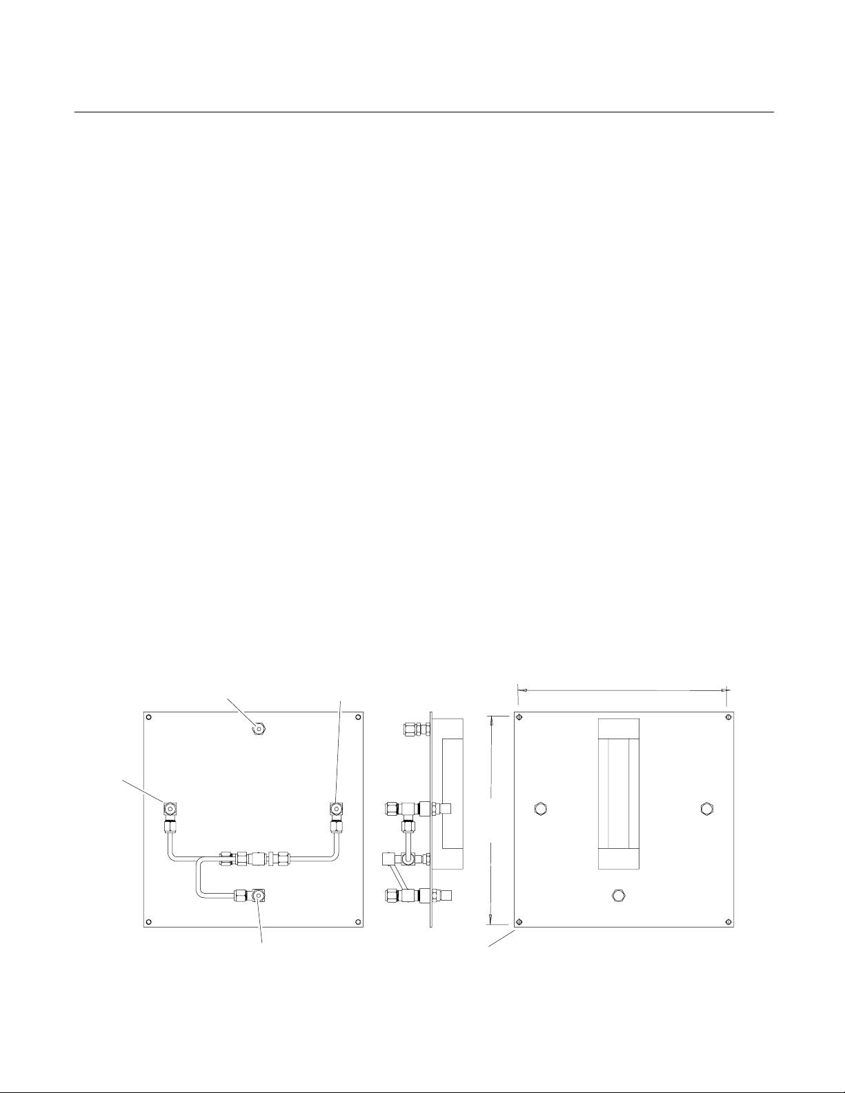
10.25
[260]
SAMPLE
Span Gas In
To Analyzer
Sample In
Zero Gas In
8.25
[210]
Mounting Holes (4)
NO. 8 Flat Head Screw
ZERO SPAN
Figure 2-1. Gas Selector Panel for Thermal Conductivity Cell with Sealed-In Reference Gas
Rosemount Analytical Inc. A Division of Emerson Process Management Installation 2-1
Page 20

Instruction Manual
748451-B
March 2002
Model CAT7
Sample Gas
To Analyzer
Sample Inlet
To Analyzer
Ref Gas Inlet
Downscale Calibration Gas
1.25
[32]
DOWNSCALE
CALIBRATION GAS
10.25
[260]
8.25
[210]
REF SAMPLE
UPSCALE
CALIBRATION GAS
3.25
[83]
.12
[3]
Mounting Holes (4)
NO. 8 Flat Head Screw
Ref Gas
Upscale Calibration Gas
Figure 2-2. Gas Selector Panel for Thermal Conductivity Cell Using Flowing Reference Gas
SAMPLE
REF
2-2 Installation Rosemount Analytical Inc. A Division of Emerson Process Management
Page 21

Model CAT7
Instruction Manual
748451-B
March 2002
2-5 UNPACKING
The Model CAT7 Thermal Conductivity Analyzer is a precision instrument and should be
handled carefully. Carefully examine the
shipping carton and contents for signs of
damage. Immediately notify the carrier if the
carton or its contents are damaged. Retain
the carton and packing material until the instrument is operational.
2-6 GAS REQUIREMENTS
The Model CAT7 requires cylinder gases appropriate to the particular application (refer to
the Data Sheet in the rear of this manual).
Suitable gases are available from various
suppliers.
2-7 CALIBRATION GAS REQUIREMENTS
For calibration, the analyzer requires a downscale and an upscale calibration gas, both
normally specified in the Data Sheet. Proper
choice of calibration gases for a particular application depends on the composition of the
sample stream and the operating range used.
a. Sample Gas Composition
WARNING
POSSIBLE EXPLOSION HAZARD
This analyzer is of a type capable of analysis of sample gases which may be flammable. If used for analysis of such gases,
the instruments explosion-proof enclosure
must be suitable for the gas.
If explosive gases are introduced into this
analyzer, the sample containment system
must be carefully leak-checked upon installation and before initial startup, during
routine maintenance and any time the integrity of the sample containment system
is broken, to ensure the system is in leakproof condition.
Internal leaks resulting from failure to observe these precautions could result in an
explosion causing death, personal injury
or property damage.
2-9 LEAK CHECK
Pressurize the system with air or inert gas
such as nitrogen, making sure not to exceed
specified pressure limitation.
In a typical application, the sample gas
consists of two components, for example:
hydrogen in nitrogen. In this example,
hydrogen is designated the “measured
component” and nitrogen constitutes the
“background gas.”
2-8 SUPPRESSED-ZERO RANGES
With any zero-suppressed range, the
zero-concentration point for the measured
component lies off-scale, below the lower
range-limit. A typical example is 80% to
100% hydrogen in nitrogen. Here the appropriate upscale calibration gas would be pure
hydrogen. The downscale gas would have a
composition appropriate to establishing a calibration point slightly above the lower
range-limit e.g., 81% hydrogen in nitrogen.
Liberally cover all fittings, seals and other
possible sources of leakage with leak test liquid such as SNOOP (PN 837801).
Bubbling or foaming indicates leakage, which
MUST be corrected before introduction of
flammable-sample and/or application of electrical power.
Rosemount Analytical Inc. A Division of Emerson Process Management Installation 2-3
Page 22

Instruction Manual
748451-B
March 2002
Model CAT7
2-10 GAS CONNECTIONS
The analyzer and gas selector panel modules
must be interconnected according to the flow
diagram specified in the Data Sheet at the
front of this manual. Gas fittings on both
modules are tagged as to use. Fittings are
1/4-inch NPT for 1/4-inch (6.3 mm) tubing.
For interconnection, use 1/4-inch (6.3 mm)
copper or stainless steel tubing, depending on
whether the sample stream is corrosive.
Connect sample/calibration gas lines to fittings tagged “INLET” on bottom of analyzer.
Connect appropriate vent line to fitting labeled
“OUTLET.”
Follow similar procedure for reference gas, if
any.
GAS INLET
(CH1)
OUTLET
ZERO GAS
INLET1
GAS
OUTLET
(CH1)
SAMPLE
GAS INLET
SPAN GAS
1 INLET
GAS INLET
(CH2)
SPARE SPARE
SPAN GAS
2 INLET
GAS
OUTLET
(CH2)
Figure 2-3. Gas Connections – Bottom View of Analyzer
2-4 Installation Rosemount Analytical Inc. A Division of Emerson Process Management
Page 23

Model CAT7
Instruction Manual
748451-B
March 2002
Sample In
Zero
Standard
Gas
Span
Standard
Gas
Needle
Valves
113357 or 113920
Gas Selector Panel
Flowmeter
Model CAT7
Thermal Conductivity Analyzer
Reference Gas
Sealed-In
Thermal Conductivity Cell
To Vent
Figure 2-4. Connection of Analyzer Using Sealed-In Reference Gas to Associated Gas
Rosemount Analytical Inc. A Division of Emerson Process Management Installation 2-5
Page 24

Instruction Manual
748451-B
March 2002
A. DIFFERENT REFERENCE GAS AND CALIBRATION GAS
Model CAT7
Reference
Gas
Sample Gas
Downscale
Calibration
Gas
Upscale
Calibration
Gas
Needle
Valves
117195 or 118210
Gas Selector Panel
Reference
Gas
Flowmeter
Sample
Gas
Flowmeter
B. REFERENCE GAS ALSO USED AS CALIBRATION GAS
Downscale Calibration Gas Used
as Reference
Needle
Valves
117195 or 118210
Gas Selector Panel
Model CAT7
Thermal Conductivity Ana-
Thermal Conductivity Cell
Thermal Conductivity Ana-
lyzer
Model CAT7
lyzer
To
Sample
Vent
To
Reference
Vent
Sample Gas
Downscale
Calibration
Gas
Upscale
Calibration
Gas
Reference
Gas
Flowmeter
Sample
Gas
Flowmeter
Thermal Conductivity Cell
To
Sample
Vent
To
Reference
Vent
Figure 2-5. Connection of Analyzer Using Flowing Reference Gas to Associated Gas Selector Panel
2-6 Installation Rosemount Analytical Inc. A Division of Emerson Process Management
Page 25

Model CAT7
Instruction Manual
748451-B
March 2002
LINE
NEUT
GND
1234
Figure 2-6. Intrinsic Safety Box
ALARM #1 NO
ALARM #1 COM
ALARM #1 NC
ALARM #2 NO
ALARM #2 COM
+VOLT OUT
-VOLT OUT
+CUR OUT
-CUR OUT
1234 121234
ALARM #2 NC
Figure 2-7. Intrinsic Safety Box Interconnect
Rosemount Analytical Inc. A Division of Emerson Process Management Installation 2-7
Page 26

Instruction Manual
748451-B
March 2002
CAUTION
Do not plug or restrict vents.
2-11 RECORDER OUTPUT SELECTION AND CA-
BLE CONNECTIONS
If a recorder, controller, or other output device
is used, connect it to the analyzer (refer to
Figure 2-6 and Figure 2-7) via a number 22 or
number 24 AWG two-conductor shielded cable. Route the cable through conduit to the
analyzer, and into the case through the appropriate opening shown in Figure 1-1.
NOTE
Route recorder cable through a separate
conduit, not with power cable.
Model CAT7
b. Linearized Voltage Output (Optional)
1. Verify that Voltage-Output Linearizer
Board is properly inserted in J102
on the Master Board.
2. On the Master Board (Figure 2-8):
a. Verify that TB2-1 is jumpered to
TB2-4, and TB2-2 is jumped to
TB2-5.
b. Set S1 for desired voltage: 5V,
1V, .1 V, or .01 V.
3. In the Intrinsic Safety Box, connect
the recorder cable to the terminals
labeled +VOLT OUT and –VOLT
OUT (Figure 2-7).
NOTE
Output selection and cable connections for
voltage-actuated and current-actuated devices are explained in Sections 2-11a through
2-12b.
a. Standard (Non-linearized) Voltage Out-
put
1. On the Master Board (Figure 2-8):
a. Verify that TB2-1 is jumpered to
TB2-2.
b. Set S1 for desired voltage: 5V,
1V, .1V, or .01V.
2. In the Intrinsic Safety Box, connect
the recorder cable to the terminals labeled +VOLT OUT and –VOLT OUT
(Figure 2-7).
NOTE
Take the usual precautions to avoid
AC pickup. DO NOT GROUND EITHER
LEAD.
3. Connect the cable to input terminals
of the recorder; ensure that polarity is
correct.
Take the usual precautions to avoid
AC pickup. DO NOT GROUND EITHER
LEAD.
4. Connect the cable to the recorder
input terminals; ensure that polarity
is correct.
c. Isolated 4 to 20 mA Current Output
(Optional)
5. Verify that the Isolated 4 to 20 mA Current Output Board is properly inserted in J103 on the Master Board.
6. On the Master Board (Figure 2-8):
c. Verify that TB2-1 is jumpered to
TB2-2 and TB2-2 is jumpered to
TB2-6.
7. In the Intrinsic Safety Box, connect the
recorder cable to the terminals labeled +CUR OUT and -CUR OUT
(Figure 2-7).
8. Connect the cable to the recorder input
terminals; ensure that polarity is correct. Total resistance of the output
device and associated cable must not
exceed 1500 ohms.
4. Ground shield on one end only.
2-8 Installation Rosemount Analytical Inc. A Division of Emerson Process Management
Page 27

Model CAT7
11
230
A
A
A
Instruction Manual
748451-B
March 2002
C
POWER
HEATER
POWER
FAN
- + - +
CUR
VOLT
OUT
OUT
J4
1
1
5V
R4 R9 R7 R22 R26 R6 R8
TB4
R15
C2
F13
1
R12
R10
C4
R14
R19R21 R18
J2
J7
J6
1
V
S2
R2
AR1
R11
R17R20
S1
R24
R16
6 5 4 3 2 1
BOARD
OPTIONS
RESISTOR
SELECT
R27
RANGE
R1
R5
C3
C1
SPAN
R3
R2
METER
C5
C6
R23
R3
C7
U1
TB2
TP1 TP2
1
2
3
4
TB5
1
2
3
4
5
6
7
8
TB3
11
J101 J100
TP3 TP4 TP5
1
J103 J102
1
TB1
6 5 4 3 2 1
DETECTOR
R100
S1
Used to select voltage output range: 5V, 1V, 0.1V, or
.01V
AR1 gain adjust. Permits adjustment of AR1 gain from
R4
X1 to X100, to establish the sensitivity desired for
Range 1. This is the highest sensitivity range.
AR1 zero adjust. Used to eliminate voltage offset
within AR1 and Bridge, and provide zero suppression.
Setting determines attenuation factor applicable to
AR2 output, Range 3.
Setting determines attenuation factor applicable to
AR2 output Range 2.
Permits adjusting meter fullscale to agree with recorder fullscale
Used to eliminate voltage offset within AR2.
Sets the stable ±10 V source.
.01V .1V 1V 5V
DETAIL OF S1
R6, R8, R26
R9
R7
R22
R15
R16
ADJUSTMENTS
Figure 2-8. Master Board
Rosemount Analytical Inc. A Division of Emerson Process Management Installation 2-9
Page 28

Instruction Manual
748451-B
March 2002
2-12 ALARMS (OPTIONAL)
The analyzer is factory configured per customer order and requires no user adjustments.
Pins for AC power (1, 2, and 3), alarm setpoint
control (8, 10, 18, and 19), and signal from analyzer circuitry (7 and 9) are wired at the factory.
Connections of the remaining pins depend on individual application requirements.
Deadband Potentiometer
ALARM 1
LED Indicator
ALARM 1
Deadband Potentiometer
ALARM 2
Model CAT7
deadband
SET
POINT
1
deadband
If the instrument has this option, the analyzer will
have setpoint adjustment potentiometers: Alarm 1
(the Low Alarm) and Alarm 2 (the High Alarm)
(Figure 1-1) and Deadband on the alarm module
(see Figure 2-9).
NOTE
Do not adjust the setpoints on the alarm
module (Figure 2-9). Use the adjustments
from the exterior of the analyzer (Figure
1-1).
The power and input wiring (18 or 20 AWG) is
routed into the intrinsic safety box. (see Figure
2-6).
The alarm relay is in energized mode when
power is applied. Wire output to the appropriate contact (see Figure 2-7). The Form C relay contacts are rated at 5 A, 120 VDC and 1
A, 120 VAC, resistive loads.
A lit LED next to the Deadband pots indicates
the alarm is activated.
LED Indicator
ALARM 2
SET
POINT
2
Front View Of Alarm Module
span
Figure 2-9. Alarm Adjustments
The following is recommended:
1. A fuse should be inserted into the line
between the customer-supplied power
supply and the alarm module terminals in the intrinsic safety box..
2. If the alarm contacts are connected to
any device that produces radio frequency interference (RFI), the device
should be arc-suppressed (P/N
858728 Arc Suppressor is recommended).
NOTE
The Zero and Span for setting the input
voltage from the analyzer has been set at
3. The analyzer and any RFI-producing
device should operate on different AC
power sources to avoid RFI.
the factory. To check it, see Section 5-2d.
2-10 Installation Rosemount Analytical Inc. A Division of Emerson Process Management
Page 29

Model CAT7
Instruction Manual
748451-B
March 2002
Removal of AC power from the analyzer,
as in a power failure, de-energizes both
alarm module relays, setting an alarm
condition. Switching characteristics of the
ALARM 1 and ALARM 2 relays are as
follows:
Alarm 1 Relay
The ALARM 1 relay coil is de-energized
when the meter needle moves downscale
through the value that corresponds to
setpoint minus deadband. This relay coil
is energized when the needle moves upscale through the value that corresponds
to setpoint plus deadband (see Figure
2-10).
Alarm 2 Relay
The ALARM 2 relay coil is de-energized
when the meter needle moves upscale
through the value that corresponds to the
setpoint plus deadband. This relay coil is
energized when the needle moves downscale through the value that corresponds
to setpoint minus deadband (see Figure
2-10).
Fail-safe Applications
By making the appropriate connections to
the double-throw relay contacts, the operator can obtain either 1) a contact closure or contact opening for an energized
relay, or 2) a contact closure or contact
opening for a de-energized relay. For
fail-safe applications, the operator must
understand which circuit conditions are
required to achieve relay de-energization
in the event of power failure
A. Typical ALARM 1 Setting (LOW)
DEADBAND SET FOR
20% OF FULLSCALE
B. Typical ALARM 2 Setting (HIGH)
DEADBAND SET FOR
10% OF FULLSCALE
INPUT SIGNAL
Percent of Fullscale
INPUT SIGNAL
Percent of Fullscale
When input signal moves upscale through this point, the
40
30
20
55
50
45
coil of ALARM 1 relay (K1) is energized, providing
continuity between the common and normally-closed
contacts of the relay.
ALARM 1 Setpoint
When input signal moves downscale through this point, the
coil of ALARM 1 relay (K1) is de-energized, providing
continuity between the common and normally-open
contacts of the relay.
When input signal moves upscale through this point, the
coil of ALARM 2 relay (K2) is de-energized, providing
continuity between the common and normally-open
contacts of the relay.
ALARM 2 Setpoint
When input signal moves upscale through this point, the
coil of ALARM 2 relay (K2) is energized, providing
continuity between the common and normally-closed
contacts of the relay.
Figure 2-10. Typical Alarm Settings
Rosemount Analytical Inc. A Division of Emerson Process Management Installation 2-11
Page 30

Instruction Manual
748451-B
March 2002
Model CAT7
2-13 LINEARIZED VOLTAGE, TWO RANGES (OP-
TIONAL)
1. Verify that the Voltage Output Linearizer
Board is properly inserted in both J102
and J103.
2. On the Master Board (Figure 2-8):
a. Verify that TB2-1 is jumpered to
TB2-4, and TB2-4 is jumped to TB2-6.
b. Select desired range on S1.
3. In the intrinsic safety box (Figure 2-7) connect recorder cable to the terminals labeled +VOLT OUT and –VOLT OUT.
NOTE
Take the usual precautions to avoid AC
pickup. DO NOT GROUND EITHER LEAD.
4. Connect the cable to the recorder input
terminals; ensure that polarity is correct.
2-14 LINEARIZED VOLTAGE AND ISOLATED 4
TO 20 MA CURRENT OUTPUT (OPTIONAL)
1. Verify that the Voltage Output Linearizer
Board is properly inserted in J102 on the
Master Board (Figure 2-8).
2. Verify that the Isolated 4 to 20 mA Current
Output Board is properly inserted in J103
on the Master Board (Figure 2-8).
3. On the Master Board (Figure 2-8):
a. Verify that TB2-1 is jumped to TB2-4,
TB2-2 is jumped to TB2-5, and TB2-5
is jumped to TB2-6.
b. Set S1 for the desired voltage: 5 V, 1
V, .1 V, or .01 V.
4. In the Intrinsic Safety Box (Figure 2-7)
connect the recorder cable to the terminals labeled +VOLT OUT and –VOLT
OUT.
NOTE
Take the usual precautions to avoid AC
pickup. DO NOT GROUND EITHER LEAD.
5. In the Intrinsic Safety Box (Figure 2-7)
connect the recorder cable to the terminals labeled +CUR OUT and –CUR OUT.
6. Connect the cable to the recorder CURRENT input terminals; ensure that polarity
is correct.
2-12 Installation Rosemount Analytical Inc. A Division of Emerson Process Management
Page 31

Model CAT7
Instruction Manual
748451-B
March 2002
2-15 ELECTRICAL POWER CONNECTIONS
DANGER
ELECTRICAL SHOCK HAZARD
For safety and proper performance, this
instrument must be connected to a properly grounded three-wire source of power.
NOTE
Before supplying electrical power to analyzer, disconnect the red lead from the
bridge to TB1-1 or TB1-2 (depending on
bridge polarity). This action disconnects
power to the bridge (see drawing 661562).
To safeguard against filament damage,
this lead should remain disconnected until
proper gas flow has been established.
SENSOR J18
400A 880 951E
R10 R11 R7 R8
C2
CR1
C
B
Q2
R17 R16 R12 CR
R4
R3
C1
E
+
Q1
K
A
TEMP CONTROL BD
The analyzer is supplied, as ordered, for operation on 107 to 127 or 214 to 254 VAC,
50/60 Hz, 250 watts. Verify that the power
source conforms to the requirements of the
individual instrument as noted on the name
rating plate. Ensure that switches S2 on the
Master Board (see Figure 2-8) and S3 on the
case heater temperature control board (see
Figure 2-11) are set to required voltage.
Electrical power is supplied to the analyzer via
a customer-supplied three-conductor cable,
type SJT, minimum wire size 18 AWG. Route
the power cable through conduit and into the
appropriate opening in the instrument case
(see drawing 661318 and Figure 1-1). In the
Intrinsic Safety Box, connect power cable
leads to terminals 4 (LINE), 3 (NEUT), and 2
(GND). See Figure 2-7.
Set switch window for voltage required
S3
POWER
SUPPLY
1
R2R1
G
R6
C3
AR1
R13
R9 R5
CR
1
E
B
Q3
C
TEST
J19
J11
R15
POWER
LINE
J5
C4
3 2 1
R14
1
U1
1 2 1 2 3
T.I.F. HEATER
U2
J17
2
3
1
S3
230
115
115
Figure 2-11. Case Heater Temperature Control Board
Rosemount Analytical Inc. A Division of Emerson Process Management Installation 2-13
Page 32

Instruction Manual
748451-B
March 2002
Model CAT7
2-14 Installation Rosemount Analytical Inc. A Division of Emerson Process Management
Page 33

Model CAT7
Instruction Manual
748451-B
March 2002
SECTION 3
OPERATION
3-1 ANALYZER CONTROLS AND ADJUST-
MENTS
Normal operation of the analyzer involves
adjustments of only the ZERO, SPAN, and
RANGE Switch, if provided. See Figure 1-1.
The various internal adjustments are factory
set and normally do not require readjustment
except after replacement of a circuit board or
major component. Refer to Section 1.
3-2 GAS SELECTOR PANEL CONTROLS
The controls provided on the optional gas selector panel will depend on the application.
For use of sealed-in reference gas, refer to
Figure 2-1 and Figure 2-4. For flowing reference gas, refer to Figure 2-2 and Figure 2-5.
3-3 STARTUP PROCEDURE
If explosive gases are introduced into this
analyzer, the sample containment system
must be carefully leak-checked upon installation and before initial startup, during
routine maintenance and any time the integrity of the sample containment system
is broken, to ensure the system is in leakproof condition. Leak-check instructions
are provided in Section 2-9.
Internal leaks resulting from failure to observe these precautions could result in an
explosion causing death, personal injury
or property damage.
NOTE:
Never apply power to analyzer without gas
flowing. The filaments in the cell tend to
deteriorate faster than normal.
Board (depending on detector bridge polarity). This action disconnects power to
the bridge. To safeguard against filament
damage, this lead should remain disconnected until proper gas flow has been established. Refer to drawing 661562.
After performing a leak check, start up the
analyzer as follows:
1. Set regulators on the gas cylinders for a
supply pressure of 10 to 50 psig f(69 to
345 kPa).
2. Provide a sample flow of 50 to 350
cc/minute through the analyzer. A rate of
250 cc/minute is recommended unless
faster flow is desired to reduce sample
transport time.
3. If the thermal conductivity cell uses flowing reference gas, provide a reference
flow of 5 to 50 cc/minute.
4. Apply power to the analyzer. The filaments will now begin to heat. Verify
proper flow of sample gas and flowing
reference gas, if used.
5. Allow the analyzer to warm-up for a minimum of six hours to ensure temperature
equilibrium.
NOTE:
If ambient temperature is below 60°F
(15.6°C), or if the temperature will go below
60°F (15.6°C) within the next six hours, allow a minimum of 12 hours for the instrument to stabilize.
Startup is now complete; the analyzer is ready
for calibration per Section 3-4.
NOTE:
Before supplying electrical power to the
analyzer, disconnect the red lead from the
bridge to TB1-1 or TB1-2 on the Master
Rosemount Analytical Inc. A Division of Emerson Process Management Operation 3-1
Page 34

Instruction Manual
748451-B
March 2002
Model CAT7
3-4 CALIBRATION
1. Set downscale calibration point as follows:
a. On the analyzer, set SPAN control to
mid-scale (five turns). If the analyzer
has a RANGE Switch, set it at Range
1, the highest sensitivity range.
b. Admit downscale calibration gas to the
analyzer at the same flow rate as is
used for sample gas. Wait for the
reading on the meter or recorder to
stabilize.
c. On the analyzer, adjust the ZERO
control so that the reading on the meter or recorder is appropriate to the
downscale calibration gas.
d. If a proper reading is unobtainable by
adjustment of the ZERO control, refer
to Section 5-2b.
2. Set upscale calibration point as follows:
a. If the analyzer has a RANGE switch,
set it for the desired range.
b. Admit upscale calibration gas to the
analyzer at the same flow rate as is
used for sample gas. Wait for the
reading on the meter or recorder to
stabilize.
c. Adjust the SPAN control so that the
reading on the meter or recorder is
appropriate to the upscale calibration
gas.
If a proper reading is unobtainable by adjustment of the SPAN control, refer to Section 1,
Service and Maintenance.
After the downscale and upscale calibration
points have been established, the analyzer is
ready for routine operation.
If the analyzer has Suppressed-Zero Ranges
and does not calibrate properly, refer to Section 5-3 for Suppressed Zero Adjustment.
3-2 Operation Rosemount Analytical Inc. A Division of Emerson Process Management
Page 35

Model CAT7
Instruction Manual
748451-B
March 2002
SECTION 4
THEORY
4-1 THERMAL CONDUCTIVITY CELL AND AS-
SOCIATED BRIDGE ADJUSTMENTS
Within the thermal conductivity cell are four
resistive filaments suspended in individual
cavities of a metal block (Figure 4-1A) and
connected electrically as legs of a Wheatstone bridge (Figure 4-1B). Although physically the cell block is one piece, functionally it
may be considered to have two sides as
shown:
Sample Side
Two filaments that constitute opposite legs of
the bridge are positioned in a passage that
receives a continuous flow of the sample gas.
Reference Side
The remaining two filaments are positioned in
a passage filled with the reference gas. Depending on the application, the reference gas
may flow continuously through the passage,
or it may be sealed within the cell.
The Bridge Voltage Power Supply is connected, via a 20-ohm dropping resistor, to the
bridge (See Section 4-5). The power supply
output is adjusted to provide an appropriate
voltage across bridge terminals 1(+) and 2(-).
An electric current flows through the filaments,
heating them and thus increasing their electrical resistance. The heat-dissipation rate for
each filament depends on the thermal conductivity of the surrounding gas. Initially, with
downscale calibration gas flowing through the
sample and reference sides of the
flow-through configuration, R26 is set for zero
bridge-output signal. During subsequent
analysis of the sample stream, any change in
the relative proportions of the components
passing through the sample side changes the
thermal conductivity of the gas mixture, caus-
ing a temperature differential between sample
and reference filaments. The resultant
change in filament resistance unbalances the
bridge.
The bridge-imbalance signal is routed to the
Master Board, where it is processed to drive
the meter and recording device, if used (see
Section 4-2).
Periodically, downscale calibration gas is
passed through the cell, and the ZERO Pot is
adjusted for an appropriate reading on the
meter or recorder.
4-2 MASTER BOARD
The Master Board, Figure 2-8, provides two
stages of amplification utilizing integrated-circuit amplifiers AR1 and AR2.
a. Functions Associated with AR1
AR1: Gain Adjust Potentiometer R4.
This screwdriver-adjustable, factory-set
trimming potentiometer determines feedback resistance for AR1 and thus permits
adjustment of AR1 gain from X1 to X100.
This adjustment sets the sensitivity for
Range 1, i.e., the highest-sensitivity
range.
Range Provisions: In the basic single-range Model CAT7, a jumper is connected from TB3-1 to TB3-4, thus routing
the unattenuated output from AR1 directly
to the non-inverting input of AR2. During
factory assembly of a dual-range or triple-range instrument, the jumper is omitted and a RANGE Switch is connected as
shown below. The output from AR1 is
then routed to AR2 through a network that
provides adjustable attenuation for ranges
2 and 3.
Rosemount Analytical Inc. A Division of Emerson Process Management Theory 4-1
Page 36

Instruction Manual
748451-B
March 2002
RANGE AR1 OUTPUT ATTENUATION RANGE SWITCH POSITION TB3 POSITION
1 X1, fixed 1 1
2 adjustable by R7 2 2
3 adjustable by R9 3 3
Model CAT7
Table 4-1. Range Switch Connections
b. Coarse zero and zero-suppression
Pots R26, R6 or R8, depending upon
range number, provide the zero correction
at the non-inverting input of AR1.
c. Functions Associated with AR2
AR2 Zero Adjustment Potentiometer R1:
This screwdriver-adjustable, factory-set
trimming potentiometer is used to eliminate voltage offset within AR2. When the
input signal is zero, R15 is adjusted so
that the output signal also is zero.
SPAN Control: This potentiometer provides continuously variable adjustment of
closed-loop gain for AR2, to permit establishing an upscale calibration point on the
meter scale or recorder chart. With upscale calibration gas flowing through the
analyzer, the SPAN Control is adjusted
for the appropriate reading.
d. Meter
The meter is connected from TB3-7 to
TB3-8. Potentiometer R22 permits adjusting meter sensitivity so that meter fullscale agrees with recorder fullscale.
e. Output Selection Switch S1
4-3 VOLTAGE OUTPUT LINEARIZER BOARD
OPTION
The output signal from the Master Board is a
function of the degree of imbalance in the
bridge circuit, but is not linear with respect to
the concentration of the measured component. Providing that the non-linearity of the
calibration curve does not exceed 20% at
midscale (for 50 % H
put Linearizer Board may be used to equip a
given operating range for linear readout of
concentration on the meter and on a potentiometric recorder.
Straightening of the concentration-vs.-output
curve is accomplished by sequential adjustment of eight odd-numbered trimming potentiometers designated R19 through R33. Each
pot controls the gain of an associated operational amplifier.
During factory checkout of a linearizer circuit
board, potentiometers R19 through R33 are
initially set at midrange. With zero input signal applied to the linearizer circuit, ZERO potentiometer R35 is adjusted for zero output.
Then an appropriate low-level signal is applied to the input, and R19 is adjusted for fullscale output. The procedure is repeated as
many times as required to obtain properly
linearized output.
max.), the Voltage Out-
2
The desired output is obtained by appropriate selection of switch contacts: 5V,
1V, .1V, or .01V.
4-2 Theory Rosemount Analytical Inc. A Division of Emerson Process Management
Page 37

Model CAT7
A. Sectional View of Thermal Conductivity Cell
Instruction Manual
748451-B
March 2002
Thermal Conductivity
Cell Block
Sample
Gas Out
Reference
Filaments
Reference *
Gas In
Sample Gas In
* Reference Ports Capped if Cell
Uses Sealed-In, Non-Flowing Reference Gas.
B. Functional Diagram of Bridge Circuit
3
0.5
Front Panel Zero
Potentiometer
4
O-Ring
Seals
Sample Filaments
NOTE: Cell Block Sectioned
Through Sample Side.
Section Through
Reference side is
Similar.
6
0.5
7
Reference Flow
1
Rosemount Analytical Inc. A Division of Emerson Process Management Theory 4-3
0.5 20
5
Resistor values are in ohms.
Bridge Power
Supply (+)
Figure 4-1. Thermal Conductivity Cell
Sample Flow
2
Bridge Power
Supply (-)
0.5
8
Page 38

Instruction Manual
748451-B
March 2002
Model CAT7
4-4 ISOLATED 4 TO 20 MA CURRENT OUTPUT
BOARD OPTION
This option provides isolated current output
for applications which require 4 to 20 mA into
a maximum load of 1500 ohms. This output is
NOT linearized. A description of the board
and the functions of its main components follows.
The purpose of the Isolated Current-Output
Board is to convert an input signal of 0 to -5 V
to an isolated output signal of 4 to 20 mA.
With a zero voltage at the input, R6 is adjusted so that the output at AR1 is 1 V. The
gain of AR1 is .8 so that an input of 0 to -5 V
is converted to 1 to 5 V. This voltage is fed to
a variable output level-inverter consisting of
AR2, Q1, Q2, and T1. T1 has two identical
output windings, each with a rectified DC output. One is used to provide feedback to the
inverter input of AR2. The other is used as an
isolated output to drive AR3 and Q3 with a 1
to 5 V signal across R16. Trim-pot R17 is
adjusted to provide a span of 4 to 20 mA.
This current is presented to the collector of Q3
and is capable of driving loads of up to 1500
ohms.
4-5 BRIDGE POWER SUPPLY
The regulated, adjustable voltage required for
the thermal conductivity bridge (Section 4-1)
is provided by the Bridge Power Supply. It
consists of a power transformer, fullwave rectifiers CR1 and CR2, voltage regulator Q1,
and an RC filter network. Bridge voltage, as
measured between bridge terminals 1(+) and
2(-), is adjustable from 5 to 13 VDC via R2.
Proper setting depends primarily on filament
material: 3 to 4 VDC for tungsten; 5 to 12
VDC for Hitempco. Bridge voltage is factory-set as required for the application (see
Data Sheet) and normally does not require
readjustment unless the power supply is replaced.
619710, power transformer T1 has three secondary that are used as follows:
38 VAC center-tapped secondary
Powers both 15 volt supplies through diode
bridge CR1 and filter capacitors C1 and C4.
The adjustable positive regulator, VR1, is set
by voltage divider R1, R2 and R3 and its output is applied to pin A of the circuit board and
to test point TP1. Potentiometer R2 should be
adjusted to +15.5 VDC ±50 mVDC.
The negative DC, regulated by VR2 is applied
to pin D of the circuit board.
The center tap is the common reference for
both the +15 and -15 volt supplies and is applied to pin R of the circuit board and to test
point TP2.
Both outputs are used for individual amplifiers
on the various circuit boards.
90-volt center-tapped secondary
Drives a rectifier circuit on the optional Current Output Board. The transformer winding
and the associated circuit constitute a floating
power supply for the emitter-follower stage.
9.5 VAC secondary
Drives a +5 VDC supply not used in this instrument.
4-7 DETECTOR BLOCKS
There are two types of detector configurations; flowing reference and sealed nitrogen
reference. The sealed reference with nitrogen
can be recharged by flowing nitrogen through
the reference and closing the plugs. Three
filament types are available: tungsten,
Hitempco, and gold-sheathed tungsten.
4-6 ±15 VOLT POWER SUPPLY
The ±15 Volt Power Supply plugged into J101
of the Master Board, provides power for the
various circuits. As shown in schematic
4-4 Theory Rosemount Analytical Inc. A Division of Emerson Process Management
4-8 CASE TEMPERATURE CONTROLLER AS-
SEMBLY
The case Temperature Controller Assembly
maintains an approximate 117°F (47°C) temperature within the instrument.
Page 39

Model CAT7
Instruction Manual
748451-B
March 2002
Changes in case temperature affect the resistance of the sensor connected to J18. This
in turn changes the bias of amplifier AR1,
which controls the input to the case heater via
switch U2. The heater receives power
through pins 3, 4 and/or 5, depending on the
voltage selected at switch S3. A thermal fuse
at J5 prevents the case from overheating.
4-9 DUAL ALARMS OPTION
Instruments with optional Dual Alarms have
two pots on the front door which are used to
select setpoints. The scales on the nameplate designate setpoints from 0 to 100%.
The module plugs into a socket, which is part
of a terminal block mounted onto the chassis
of the instrument. A marker on the alarm
module indicates the function of each socket
pin.
This unit is factory configured and requires no
user adjustment. Pins for AC power (1, 2, and
3), alarm setpoint control (8, 10, 18, and 19),
and signal from analyzer circuitry (7 and 9)
are wired at the factory.
Connections of the remaining pins depend
upon the application. The relays are rated at
1.0 A, 120 VAC and 5.0 A, 120 VDC, form C,
resistive loads.
Rosemount Analytical Inc. A Division of Emerson Process Management Theory 4-5
Page 40

Instruction Manual
748451-B
March 2002
Model CAT7
4-6 Theory Rosemount Analytical Inc. A Division of Emerson Process Management
Page 41

Model CAT7
Instruction Manual
748451-B
March 2002
SECTION 5
SERVICE AND MAINTENANCE
DANGER
POSSIBLE EXPLOSION HAZARD
If explosive gases are introduced into this
analyzer, the sample containment system
must be carefully leak-checked upon installation and before initial startup, during
routine maintenance and any time the integrity of the sample containment system
is broken, to ensure the system is in leakproof condition. Leak-check instructions
are provided in Section 2-9.
Internal leaks resulting from failure to observe these precautions could result in an
explosion causing death, personal injury
or property damage.
In troubleshooting, the basic approach is to
isolate the analyzer from the sample and the
sample-handling system.
First admit downscale and upscale standard
gases to analyzer and note response:
1. If performance is normal with standard
gases, although not with sample gas, the
sample and the sample-handling system
are suspect. Check these areas.
2. If analyzer gives off-scale or erratic readings with standard gases, as well as with
sample gas, the problem might be the
filaments or the electronic circuitry. To
isolate the malfunction, substitute fixed
precision resistors of appropriate value for
the filaments. Hitempco filaments have a
cold resistance of 72 ohms. Tungsten
filaments have a cold resistance of 18
ohms. Filament connections are shown in
schematic 654616. With appropriate resistors substituted for the filaments, attempt to balance the bridge as follows:
a. If bridge balance is obtained with the
fixed resistors, the filaments are
probably defective and should be replaced.
b. If bridge balance is unobtainable with
the fixed resistors, the problem might
be the electronic circuitry. Substitute
each circuit board, in turn, until proper
operation is obtained.
5-1 THERMAL CONDUCTIVITY CELL
The thermal conductivity cell and associated
elements of the bridge are mounted inside the
analyzer case, within a thermally-insulated
compartment.
Depending on the bridge current level, the
filaments gradually become mismatched, and
eventually burn out. Normal progression of
symptoms is baseline drift. Sealed reference
cells must be serviced by the factory.
If the cell uses flowing reference gas, the filaments may be replaced by the user. Refer to
Figure 4-1 and the parts list in Section 1.
Filaments are sold as matched sets. If one
must be replaced, its mate also must be replaced. Electrically, the filaments are mated
across the diagonals of the cell. Refer to
Figure 4-1B. The filament across points 3 and
1 corresponds to the filament across 8 and 1,
and the filament across points 6 and 2 corresponds to the filament across 5 and 2.
Rosemount Analytical Inc. A Division of Emerson Process Management Service and Maintenance 5-1
Page 42

Instruction Manual
748451-B
March 2002
Model CAT7
5-2 ELECTRONIC CIRCUITRY
a. Amplifier Zero Adjustments
The zero adjustments on the Master
Board are factory set and normally do not
require readjustment except after replacement of a major component. If readjustment becomes necessary, use
following procedure:
AR2 Zero Adjustment (Refer to Figure
2-8):
1. Open the input to AR2. In a single-range instrument, this is done by
disconnecting the jumper from TB3-1
to TB3-4.
2. Ground the input of AR2 by connecting a jumper from TB3-4 to TP1
(GND).
3. Adjust R15 for 0 VDC output signal at
TB4-2.
4. Restore connections to normal.
b. Bridge Balance and Range Sensitivity
Adjustments
Perform start-up procedure in Section 3-3,
then proceed as follows:
Sensitivity Adjustment(s) are:
1. Admit upscale calibration gas to the
analyzer at the same flow rate as is
used for the sample gas. Wait for
reading on meter or recorder to stabilize.
2. On the Master Board, set AR2 Gain
Adjustment R4 so that reading on the
recorder, if used, or on the meter is
appropriate to the upscale calibration
gas. Refer to data sheet or calibration curve. Range 1 sensitivity is now
properly adjusted.
3. If analyzer has more than one range,
set the RANGE Switch for Range 2.
This is the reduced sensitivity range.
Then, on the Master Board, set
Range 2 Attenuation Adjustment R7
so that the reading on the recorder, if
used, or on the meter is appropriate
to the upscale calibration gas.
4. If the analyzer has three ranges, set
the RANGE Switch for Range 3. This
is the least sensitive range. Then, on
the Master Board, set Range 3 Attenuation Adjustment R9 so that the
reading on the recorder, if used, or on
the meter is appropriate to the upscale calibration gas.
1. On the analyzer, set the ZERO and
SPAN controls to their midpoints (five
turns). If the analyzer has a RANGE
Switch, set it to Range 1, the highest-sensitivity range.
2. Admit downscale calibration gas to
the analyzer at the same flow rate as
is used for the sample gas. Wait for
the reading on the meter or recorder
to stabilize.
3. Refer to Figure 2-8 and set the Balance Adjustment on the Master
Board, (range 1 or single range R8,
range 2 R6, range 3 R26) so that the
reading on the meter or recorder is
zero or an offset value. Refer to Data
Sheet.
5-2 Service and Maintenance Rosemount Analytical Inc. A Division of Emerson Process Management
5. If previous readings were obtained on
a recorder, set the Meter 100% Adjustment R22 so that the meter fullscale matches the recorder fullscale.
If the analyzer has more than one
range, this adjustment should be
made on Range 1.
Bridge Voltage Adjustment
Bridge voltage is factory set as required
for the application (see Data Sheet) and
normally does not require readjustment
unless the bridge power supply is replaced. Bridge voltage is measured between terminals 1(-) and 2(+), and is
adjustable via R2. See schematic
613561.
Page 43

Model CAT7
Instruction Manual
748451-B
March 2002
c. Case Temperature Controller
Refer to drawing 661540. Malfunction in
this option can occur in three areas:
Heater
Check continuity with ohmmeter. Verify
that resistance is approximately 113 ohms
at 25°C.
Temperature Sensor
This is an RTD and should have approximately 550 ohms at 25°C. Check for
continuity with ohmmeter.
Thermal Fuse
The fuse opens at temperatures above
72°C. Check continuity with ohmmeter.
d. Dual Alarm Module (Optional)
This module is not user-serviceable. If
problems occur, contact Rosemount
Analytical service.
The module has Zero and Span potentiometers that set the 0 to 5 V input. To
check these, adjust the analyzer for zero
gas, set the Low Alarm set point to 0 %,
and turn the Deadband counterclockwise.
Adjust the Zero pot to trigger the alarm.
Do the same for High Alarm (ALARM 2 on
the front panel). The alarm span should
agree with the analyzer meter span. Readjust the deadbands to the desired level.
(See Figure 2-9 and Figure 2-10)
NOTE
For instruments with more than one range,
RANGE 1 is the most sensitive range; it
must be set for the highest gain. This
range should be used for the smallest
span. Always start procedure with RANGE
1 (i.e., RANGE 1 ... 95 to 100%, RANGE 2 ...
90 to 100%, RANGE 3 ... 60 to 80%).
1. Set the ZERO and SPAN controls to their
midpoints (five turns).
2. If the instrument has a Range Switch, set
it to RANGE 1.
3. On the Master Board, connect a digital
voltmeter between TB3-1 and TP1 (polarity does not matter).
4. Flow downscale calibration gas through
the sample inlet of the analyzer. Adjust
R8 until the reading on the voltmeter is
zero. The analyzer meter should also
read zero.
5. Flow upscale calibration gas through the
sample inlet of the instrument. Adjust R4
until the meter reads 100 % (fullscale).
6. Repeat steps 4 and 5 above until no adjustment is required.
If the analyzer has more than one range, repeat steps 2 through 6 with the following alterations:
Range 2
5-3 SUPPRESSED ZERO ADJUSTMENT
If the instrument has suppressed-zero ranges
and does not calibrate properly, adjust the
potentiometers located on the Master Board
(see Figure 2-8). Follow the startup procedure in Section 3-3. After the analyzer has
stabilized, use appropriate calibration gases
to make the following adjustments. Refer to
Section 2-7 for information on selecting appropriate gases.
Rosemount Analytical Inc. A Division of Emerson Process Management Service and Maintenance 5-3
Set the Range Switch to RANGE 2. In step 4,
adjust R6, and in step 5, adjust R7.
Range 3
Set the Range Switch to RANGE 3. In step 4,
adjust R26, and in step 5, adjust R9.
Page 44

Instruction Manual
748451-B
March 2002
Model CAT7
5-4 Service and Maintenance Rosemount Analytical Inc. A Division of Emerson Process Management
Page 45

Instruction Manual
748451-B
Model CAT7
March 2002
SECTION 6
REPLACEMENT PARTS
WARNING
PARTS INTEGRITY
Tampering with or unauthorized substitution of components may adversely affect safety of this product.
Use only factory-approved components for repair.
6-1 MATRIX
Each analyzer is configured per the customer sales order. Below is the CAT7 sales matrix which lists the
various configurations available.
To identify the configuration of an analyzer, locate the analyzer name-rating plate. The sales matrix identifier number appears on the analyzer name-rating plate.
CAT7 CAT7 THERMAL CONDUCTIVITY ANALYZER
Code Parameter And Background Gas
10 Hydrogen in Air
11 Hydrogen in Nitrogen
12 Hydrogen in Methane
13 Hydrogen in Argon
14 Hydrogen in Carbon Dioxide
20 Helium in Air
21 Helium in Nitrogen
22 Helium in Oxygen
23 Helium in Methane
24 Helium in Argon
25 Helium in Carbon Dioxide
26 Helium in Argon & Oxygen
90 Argon in Air
91 Argon in Nitrogen
92 Argon in Oxygen
93 Carbon Dioxide in Air
94 Carbon Dioxide in Nitrogen
95 Carbon Dioxide in Oxygen
96 Nitrogen in Argon
50 Nitrogen in Hydrogen (0-5000 ppm Range Only. Range Code 31
60 Refinery (15% Hydrocarbon – 85% N2; 100% N2; 1% Hydrogen in 99% N2). Range Code 60
61 Utilities (BD Special) (80-100% H2 in Air, 0-100% H2 in CO2 and 0-100% Air in CO2). Range Code 61
97 Corrosive Gas Mixture Application (Zero Based Ranges Only). Range Code 97
98 Corrosive Gas Mixture Application (Suppressed Range Only). Range Code 98
99 Special
Rosemount Analytical Inc. A Division of Emerson Process Management Replacement Parts 6-1
Page 46

Instruction Manual
748451-B
March 2002
Model CAT7
Code Range
14 85-100%
15 95-100%
16 99-100%
17 99.5-100%
19 Special Suppressed Range
30 0-500 ppm
31 0-5000 ppm
01 0-1%
02 0-5%
03 0-10%
04 0-15%
05 0-25%
06 0-50%
07 0-75%
08 0-100%
09 Special Zero Based Range
10 20-50%
11 45-55%
12 60-80%
13 50-100%
60 Refinery
61 Utilities
97 Corrosive Gas Mixture Application – Zero Based Range
98 Corrosive Gas Mixture Application – Suppressed Range
Code Single and Dual Range Analyzer
01 One Range, Voltage Output
02 One Range, Linearized Voltage Output
03 One Range with 4-20 mA Isolated Current Output
04 One Range, Linearized with 4-20 mA Isolated Current Output
05 Two Ranges, Voltage Output
06 Two Ranges, Range One Linearized Voltage Output
07 Two Ranges, Both Linearized Voltage Output
08 Two Ranges with 4-20 mA Isolated Current Output
09 Two Ranges, Range One Linearized Output; Both Ranges 4-20 mA Output
99 Triple Range
6-2 Replacement Parts Rosemount Analytical Inc. A Division of Emerson Process Management
Page 47

Model CAT7
Instruction Manual
748451-B
March 2002
Code Dual Range Analyzer; Second Range
14 85-100%
15 95-100%
16 99-100%
17 99.5-100%
19 Special Suppressed Range
30 0-500 ppm
31 0-5000 ppm
01 0-1%
02 0-5%
03 0-10%
04 0-15%
05 0-25%
06 0-50%
07 0-75%
08 0-100%
09 Special Zero Based Range
10 20-50%
11 45-55%
12 60-80%
13 50-100%
60 Refinery
61 Utilities
97 Corrosive Gas Mixture Application – Zero Based Range
98 Corrosive Gas Mixture Application – Suppressed Range
00 No Second Range
Code Power, Alarm, Tropicalization
01 115V, 50/60 Hz
02 115V, 50/60 Hz with Dual Alarm
03 115V, 50/60 Hz with Tropicalization
04 115V, 50/60 Hz with Dual Alarm and Tropicalization
05 230V, 50/60 Hz
06 230V, 50/60 Hz with Dual Alarm
07 230V, 50/60 Hz with Tropicalization
08 230V, 50/60 Hz with Dual Alarm and Tropicalization
CAT7 11 03 02 17 04 Example
6-2 CIRCUIT BOARD REPLACEMENT POLICY
In most situations involving a malfunction of a circuit board, it is more practical to replace the board than to
attempt isolation and replacement of the individual component. The cost of test and replacement will exceed the cost of a rebuilt assembly from the factory.
The following list does not include individual electronic components. If circumstances necessitate replacement of an individual component which can be identified by inspection or from the schematic diagrams,
obtain the replacement component from a local source of supply.
Rosemount Analytical Inc. A Division of Emerson Process Management Replacement Parts 6-3
Page 48

Instruction Manual
748451-B
March 2002
6-3 REPLACEMENT PARTS
The following parts are recommended for routine maintenance and troubleshooting of the Model CAT7
Analyzer. If the troubleshooting procedures do not resolve the problem, contact Rosemount Analytical
Customer Service Center (Section 7).
661540 Temperature Control Assembly
624006 Temperature Control Board
901913 Alarm Module
613560 Bridge Power Supply
619714
654632
654630
654628
654627
654631
654629
902444
902443
902442
1
3
3
3
3
3
3
1
1
±15V Power Supply
Detector Assembly w/Filaments Flowing Ref (Gold Sheathed Tungsten)
Detector Assembly w/Filaments Flowing Ref (Hytempco)
Detector Assembly w/Filaments Flowing Ref (Tungsten)
Detector Assembly w/Filaments Sealed Ref (Tungsten)
Detector Assembly w/Filaments Sealed Ref Nitrogen (Gold Sheathed Tungsten)
Detector Assembly w/Filaments Sealed Ref Nitrogen (Hytempco)
Filaments (Gold Sheathed Tungsten)
Filaments (Hytempco)
Filaments (Tungsten)
801566 Fuse 1.5A (230VAC)
000516 Fuse 3A (115VAC)
652816 Isolated Current Output Board
616443 Linearizer Kit (Factory Installed option. Consult factory.)
654620 Master Board
633875 Meter
Model CAT7
1
Sealed reference cells must be serviced at factory.
6-4 Replacement Parts Rosemount Analytical Inc. A Division of Emerson Process Management
Page 49

Model CAT7
Instruction Manual
748451-B
March 2002
SECTION 7
RETURN OF MATERIAL
7-1 RETURN OF MATERIAL
If factory repair of defective equipment is required, proceed as follows:
1. Secure a return authorization from a
Rosemount Analytical Inc. Sales Office or
Representative before returning the
equipment. Equipment must be returned
with complete identification in accordance
with Rosemount instructions or it will not
be accepted.
Rosemount CSC (Customer Service
Center) will provide the shipping address
for your instrument.
In no event will Rosemount be responsible for equipment returned without proper
authorization and identification.
2. Carefully pack the defective unit in a
sturdy box with sufficient shock absorbing
material to ensure no additional damage
occurs during shipping.
3. In a cover letter, describe completely:
• The symptoms that determined the
equipment is faulty.
• The environment in which the equip-
ment was operating (housing,
weather, vibration, dust, etc.).
• Site from where the equipment was
removed.
• Whether warranty or non-warranty
service is expected.
• Complete shipping instructions for the
return of the equipment.
4. Enclose a cover letter and purchase order
and ship the defective equipment according to instructions provided in the
Rosemount Return Authorization, prepaid,
to the address provided by Rosemount
CSC.
Rosemount Analytical Inc.
Process Analytical Division
Customer Service Center
1-800-433-6076
If warranty service is expected, the defective
unit will be carefully inspected and tested at
the factory. If the failure was due to the conditions listed in the standard Rosemount warranty, the defective unit will be repaired or
replaced at Rosemount’s option, and an operating unit will be returned to the customer in
accordance with the shipping instructions furnished in the cover letter.
For equipment no longer under warranty, the
equipment will be repaired at the factory and
returned as directed by the purchase order
and shipping instructions.
7-2 CUSTOMER SERVICE
For order administration, replacement Parts,
application assistance, on-site or factory repair, service or maintenance contract information, contact:
Rosemount Analytical Inc.
Process Analytical Division
Customer Service Center
1-800-433-6076
7-3 TRAINING
A comprehensive Factory Training Program of
operator and service classes is available. For
a copy of the Current Operator and Service
Training Schedule contact the Technical
Services Department at:
Rosemount Analytical Inc.
Phone: 1-714-986-7600
FAX: 1-714-577-8006
Rosemount Analytical Inc. A Division of Emerson Process Management Return of Material 7-1
Page 50

Instruction Manual
748451-B
March 2002
Model CAT7
7-2 Return of Material Rosemount Analytical Inc. A Division of Emerson Process Management
Page 51

WARRANTY
Goods and part(s) (excluding consumables) manufactured by Seller are warranted to be free from
defects in workmanship and material under normal use and service for a period of twelve (12)
months from the date of shipment by Seller. Consumables, glass electrodes, membranes, liquid
junctions, electrolyte, o-rings, etc., are warranted to be free from defects in workmanship and
material under normal use and service for a period of ninety (90) days from date of shipment by
Seller. Goods, part(s) and consumables proven by Seller to be defective in workmanship and/or
material shall be replaced or repaired, free of charge, F.O.B. Seller's factory provided that the
goods, part(s) or consumables are returned to Seller's designated factory, transportation charges
prepaid, within the twelve (12) month period of warranty in the case of goods and part(s), and in
the case of consumables, within the ninety (90) day period of warranty. This warranty shall be in
effect for replacement or repaired goods, part(s) and the remaining portion of the ninety (90) day
warranty in the case of consumables. A defect in goods, part(s) and consumables of the commercial unit shall not operate to condemn such commercial unit when such goods, part(s) and
consumables are capable of being renewed, repaired or replaced.
The Seller shall not be liable to the Buyer, or to any other person, for the loss or damage directly
or indirectly, arising from the use of the equipment or goods, from breach of any warranty, or from
any other cause. All other warranties, expressed or implied are hereby excluded.
IN CONSIDERATION OF THE HEREIN STATED PURCHASE PRICE OF THE GOODS,
SELLER GRANTS ONLY THE ABOVE STATED EXPRESS WARRANTY. NO OTHER WARRANTIES ARE GRANTED INCLUDING, BUT NOT LIMITED TO, EXPRESS AND IMPLIED
WARRANTIES OR MERCHANTABILITY AND FITNESS FOR A PARTICULAR PURPOSE.
Limitations of Remedy. SELLER SHALL NOT BE LIABLE FOR DAMAGES CAUSED BY DELAY IN PERFORMANCE. THE SOLE AND EXCLUSIVE REMEDY FOR BREACH OF WARRANTY SHALL BE LIMITED TO REPAIR OR REPLACEMENT UNDER THE STANDARD
WARRANTY CLAUSE. IN NO CASE, REGARDLESS OF THE FORM OF THE CAUSE OF ACTION, SHALL SELLER'S LIABILITY EXCEED THE PRICE TO BUYER OF THE SPECIFIC
GOODS MANUFACTURED BY SELLER GIVING RISE TO THE CAUSE OF ACTION. BUYER
AGREES THAT IN NO EVENT SHALL SELLER'S LIABILITY EXTEND TO INCLUDE INCIDENTAL OR CONSEQUENTIAL DAMAGES. CONSEQUENTIAL DAMAGES SHALL INCLUDE, BUT
ARE NOT LIMITED TO, LOSS OF ANTICIPATED PROFITS, LOSS OF USE, LOSS OF REVENUE, COST OF CAPITAL AND DAMAGE OR LOSS OF OTHER PROPERTY OR EQUIPMENT.
IN NO EVENT SHALL SELLER BE OBLIGATED TO INDEMNIFY BUYER IN ANY MANNER
NOR SHALL SELLER BE LIABLE FOR PROPERTY DAMAGE AND/OR THIRD PARTY CLAIMS
COVERED BY UMBRELLA INSURANCE AND/OR INDEMNITY COVERAGE PROVIDED TO
BUYER, ITS ASSIGNS, AND EACH SUCCESSOR INTEREST TO THE GOODS PROVIDED
HEREUNDER.
Force Majeure. Seller shall not be liable for failure to perform due to labor strikes or acts beyond
Seller's direct control.
Page 52

Instruction Manual
748451-B
March 2002
Model CAT7
Emerson Process Management
Rosemount Analytical Inc.
Process Analytic Division
1201 N. Main St.
Orrville, OH 44667-0901
T (330) 682-9010
F (330) 684-4434
E gas.csc@emersonprocess.com
ASIA - PACIFIC
Fisher-Rosemount
Singapore Private Ltd.
1 Pandan Crescent
Singapore 128461
Republic of Singapore
T 65-777-8211
F 65-777-0947
http://www.processanalytic.com
© Rosemount Analytical Inc. 2001
Fisher-Rosemount GmbH & Co.
Industriestrasse 1
63594 Hasselroth
Germany
T 49-6055-884 0
F 49-6055-884209
EUROPE, MIDDLE EAST, AFRICA
Fisher-Rosemount Ltd.
Heath Place
Bognor Regis
West Sussex PO22 9SH
England
T 44-1243-863121
F 44-1243-845354
LATIN AMERICA
Fisher - Rosemount
Av. das Americas
3333 sala 1004
Rio de Janeiro, RJ
Brazil 22631-003
T 55-21-2431-1882
Page 53

Page 54

Page 55

Page 56

Page 57

Page 58

Page 59

Page 60

Page 61

Page 62

Page 63

Page 64

 Loading...