

BINOS 100 Series Analyzers including OXYNOS 100, HYDROS 100 and CAT 100 Addendum to ETC00781 Regarding BKS 20 Hardware Upgrade-1st Ed.
Rosemount BINOS 100 Series Analyzers including OXYNOS 100, HYDROS 100 and CAT 100 Addendum to ETC00781 Regarding BKS 20 Hardware Upgrade-1st Ed. Manuals & Guides
Page 1

Instruction Sheet
HAS1xE-IS-BKS
October 2004
OXYNOS® 100, HYDROS® 100, CAT 100
Instruction Manual Addendum to Manual ETC00781
Series 100 Gas Analyzers
BINOS® 100, BINOS® 100 M
BINOS® 100 2M, BINOS® 100 F
Regarding BKS 20 Hardware Upgrade
www.EmersonProcess.com
Page 2

ESSENTIAL INSTRUCTIONS
READ THIS PAGE BEFORE PROCEEDING!
Emerson Process Management (Rosemount Analytical) designs, manufactures and tests
its products to meet many national and international standards. Because these
instruments are sophisticated technical products, you MUST properly install, use, and
maintain them to ensure they continue to operate within their normal specifications. The
following instructions MUST be adhered to and integrated into your safety program when
installing, using and maintaining Emerson Process Management (Rosemount Analytical)
products. Failure to follow the proper instructions may cause any one of the following
situations to occur: Loss of life; personal injury; property damage; damage to this
instrument; and warranty invalidation.
• Read all instructions prior to installing, operating, and servicing the product.
• If you do not understand any of the instructions, contact your Emerson Process
Management (Rosemount Analytical) representative for clarification.
• Follow all warnings, cautions, and instructions marked on and supplied with the
product.
• Inform and educate your personnel in the proper installation, operation, and
maintenance of the product.
• Install your equipment as specified in the Installation Instructions of the
appropriate Instruction Manual and per applicable local and national codes.
Connect all products to the proper electrical and pressure sources.
• T o ensure proper performance, use qualified personnel to install, operate, update,
program, and maintain the product.
• When replacement parts are required, ensure that qualified people use replacement
parts specified by Emerson Process Management (Rosemount Analytical).
Unauthorized parts and procedures can affect the product’s performance, place the
safe operation of your process at risk, and VOID YOUR W ARRANTY. Look-alike
substitutions may result in fire, electrical hazards, or improper operation.
• Ensure that all equipment doors are closed and protective covers are in place,
except when maintenance is being performed by qualified persons, to prevent
electrical shock and personal injury.
The information contained in this document is subject to change without notice.
1st edition: 2004-10
Emerson Process Management
Manufacturing GmbH & Co. OHG
Industriestrasse 1
D-63594 Hasselroth
Germany
T +49 (0) 6055 884-0
F +49 (0) 6055 884-209
Internet: www.EmersonProcess.com
Page 3

Instruction Sheet
HAS1xE-IS-BKS
10/2004
BKS 20 Upgrade
INTRODUCTION
The BINOS® 100 series analyzers are subject
to a consistent improvement as well as all
EMERSON PROCESS MANAGEMENT
products. Within this improvement the main
board BKS 10 was replaced by the successor
BKS 20.
Due to the short term development of this new
printed circuit board the BINOS® 100 analyzer
series instruction manual ETC00781 could not
be adapted in time. This means that all
illustrations and references within this manual
still refer to the old board.
While during operation this is not a
disadvantage, it may cause problems when
servicing and maintaining the analyzer .
For this reasons EMERSON PROCESS
MANAGEMENT has created this instruction
sheet.
This Instruction sheet is
intended to be used in
conjunction with the
BINOS® 100 analyzer series
instruction manual ETC00781
delivered together with the
analyzer.
It deals with service aspects and
replaces respectively
completes the corresponding
chapters of the original
instruction manual ETC00781.
We recommend to replace the
corresponding chapters inside the manual
by the chapters of this sheet. For this the
pages in this sheet are numbered
corresponding to the manual.
A new section is the attachment containing
block diagrams for the different analyzer
variations.
Contents
Chapter 16............... List of Failures.......................................................... Pages 16-1 to 16-8
Chapter 17............... Measuring Points ..................................................... Pages 17-1 to 17-6
Chapter 18............... Allocation of Connectors........................................... Pages 18-1 to 18-6
Chapter 19............... BKS Jumper Configuration....................................... Pages 19-1 to 19-2
Attachment............... Block Diagrams ...........................................................Pages A-1 to A-6
EMERSON Process Management Manufacturing GmbH & Co. OHG I-1
Page 4

BKS 20 Upgrade
Instruction Sheet
HAS1xE-IS-BKS
10/2004
EMERSON Process Management Manufacturing GmbH & Co. OHGI-2
Page 5

Instruction Sheet
HAS1xE-IS-BKS
10/2004
Error Code Possible Reasons Check / Correct
16. List of Failures
BKS 20 Upgrade
Some of the failures possibly coming up during
operation are reported on the displays by the
use of error codes.
In such a case the display's show the current
concentration value alternating with
(E = error , XX = code).
The following table lists all error codes, some
related reasons and measures to repair .
Error Code Possible Reasons Check / Correct
1. Displays are “switched OFF”
If there is an "error message", an optional
digital status signal "Failure" may be set
(see chapter 10.3)!
Be sure to observe the safety
measures while working at the
analyzer!
1. Press any key.
Check parameter dOFF
(see chapter 8.7).
2. Voltage supply missing
Display dark
BINOS® 100 F
3. Connection front panel /BKS
interrupted
EMERSON Process Management Manufacturing GmbH & Co. OHG 16-1
2. Check connection mains to P/S
Check external power supply
Check electrical supply
(see Fig. 1-5 and 1-6, Item 3
Fig. 1-7 to 1-9, Item 10).
Check internal fuse on board BKS
(s. page 18-1)
Check internal fuses F1 and F2
3. Check connection
BKB to BKS (X1) (see chapter 18.1).
Page 6

BKS 20 Upgrade
Error Code Possible Reasons Check / Correct
Instruction Sheet
HAS1xE-IS-BKS
10/2004
Flashing
Channel 1
Channel 2
Battery buffer failure
The EPROM default
values have been loaded
If only one code is shown:
1. A/D converter of related
channel is not driven correctly
If both codes are shown:
2. Positive or negative
reference voltage missing
Check, if Jumper J 7
is set (see chapter 19.).
Replace battery,
if battery voltage < 3,5 V
(BKS - Jumper J7 set).
The error code is cleared by pressing
any key or by serial interface
instruction $627.
1. Switch analyzer off and then on again.
2. Check reference voltage
(see chapter 17.1.2/17.1.3).
A/D Conversion Interrupt
missing
Temperature compensation
incorrect
3. Light barrier signal missing
4. IR channel:
Chopper drive inoperative
5. Supply voltage
(internal 6 V DC) missing
1. Failed to start A/Dconversion for temperature
channel
2. Supply voltage
(internal 6 V DC) absent.
3. Check connection X9 / light barrier
(see chapter 18.)
Solder bridge LB 18 not configured
properly, check measuring point (17.1.5)
4. Check connection X2 / chopper drive
(see chapter 18)
Check measuring point (17.1.4)
5. Check measuring point (17.1.1)
1. Switch analyzer off and then on again.
2. Check measuring point 17.1.1
EMERSON Process Management Manufacturing GmbH & Co. OHG16-2
Page 7

Instruction Sheet
HAS1xE-IS-BKS
10/2004
Error Code Possible Reasons Check / Correct
BKS 20 Upgrade
Channel 1
Channel 2
Tolerance error
Channel 1
Channel 2
Tolerance error
Zero gas value differs from
zero more than 10% of
measuring range .
Channel 1
Channel 2
1. Span gas in use exceeds
measuring range
1. Wrong zero gas in use.
2. IR channel:
Photometer section
contaminated.
3. Analyzer not calibrated.
1. Wrong nominal value.
2. Wrong span gas in use.
1. Check span gas in use and replace
by gas with correct nominal value
1. Check zero gas in use.
2. Check analysis cell and windows for
contamination.
Clean contaminated parts
(see chapter 24.3).
3. Switch off the tolerance check
before starting a calibration
(see chapter 8.6).
1. Enter the correct nominal value
(refer to span gas bottle certificate)
(see chapter 9.1.2).
2. Check span gas in use.
Use another or a new gas bottle.
Enter the correct nominal value
Tolerance error
Span gas value differs from
nominal value more than
10% .
Channel 1
Channel 2
Measuring value more than
10% over full scale range.
EMERSON Process Management Manufacturing GmbH & Co. OHG 16-3
3. IR channel:
Photometer section
contaminated.
4. Analyzer not calibrated.
1. Concentration of sample gas
too high.
3. Check analysis cell and windows for
contamination.
Clean contaminated parts
(see chapter 24.3).
4. Switch off the tolerance check
before starting a calibration
(see chapter 8.6).
1. Check concentration of sample gas
2. Use an analyzer suitable for
the existing concentration range
Page 8

BKS 20 Upgrade
Error Code Possible Reasons Check / Correct
Instruction Sheet
HAS1xE-IS-BKS
10/2004
Channel 1
Channel 2
Failure while entering limits
Channel 1
Channel 2
1. Absorber in NVE:
lifetime cycle ended
2. Parameter “AbS.” not set to “0”
XON (serial interface)
timed out.
wrong limit value entered due
to shift of decimal point
Wrong nominal value entered
due to shift of decimal point
1. Replace absorber. Enter menu
“SYS.-PArA” and set parameter
“AbS” to “2” (new life time cycle)
2. Enter menu “SYS.-PArA” and set
parameter “AbS.” to “0”
XON - character is missing while
driving the serial interface
(time out > 60 s).
Correct limit value in line “LI.”
1. Correct nominal value by performing
a span gas calibration
2. Correct nominal value via serial
interface by sending “$029”
Wrong nominal value entered
for span gas
Channel 1
Channel 2
Wrong offset value entered
Wrong offset value entered
due to shift of decimal point
EMERSON Process Management Manufacturing GmbH & Co. OHG16-4
1. Correct offset value “OFS.x”
Page 9

Instruction Sheet
HAS1xE-IS-BKS
10/2004
Error Code Possible Reasons Check / Correct
BKS 20 Upgrade
Pressure measurement
failure
EPROM checksum
failure
Test for SRAM - IC's
failed
1. Measuring range failure.
2. Connection faulty.
3. Pressure sensor faulty.
1. EPROM faulty.
2. BKS faulty.
SRAM IC's / BKS
faulty.
1. Pressure not within the sensor
measuring range
2. Check connection P1 (at BAF 01) /
pressure sensor (see chapter 18.).
3. Replace pressure sensor.
1. Replace EPROM (see chapter 28.).
2. Replace BKS.
Replace BKS.
Analog output signal
missing
Fluctuating or
erroneous display
BKS faulty.
1. Leakage in gas path
2. Ambient air contains gas
component to be measured
in a concentration influencing
measurement
Replace BKS.
1. Perform a leakage test
(see chapter 22)
2. Replace absorber material for IR
sources and chopper housing
Use sealed photometer (Option)
Purge analyzer with inert gas
EMERSON Process Management Manufacturing GmbH & Co. OHG 16-5
Page 10

BKS 20 Upgrade
Error Code Possible Reasons Check / Correct
Instruction Sheet
HAS1xE-IS-BKS
10/2004
Fluctuating or
erroneous display
(cont’d)
3. Gas pressure subject to
considerable variation
4. IR detector / Oxygen senor
not connected.
5. Electrochemical oxygen
sensor is weared
6. IR channel:
IR source not connected
or faulty.
3. Check the gas lines preceding and
beyond the sensor cell.
Eliminate any restrictions
beyond the gas outlet fitting.
Reduce pump rate or flow rate.
4. Check connections:
BKS X5 detector channel 1
(Oxygen sensor or IR detector)
BKS X6 detector channel 2
(IR detector)
(see 18.)
5. Replace sensor (see 25.)
6. Checkconnection:
BKS X3(1/2) - IR source channel 1
BKS X4(1/2) - IR source channel 2
(see 18.)
7. Faulty analog
preamplifying
8. Contamination of the gas
paths.
If IR source housing is cold:
For dual IR channel analyzer
interchange the two IR sources.
Replace the suspect IR source
(see 24.2).
7. Check measuring point 17.1.7 or
17.2.1 resp.
8. Check analysis cell and windows for
contamination.
Clean contaminated parts
(see 24.3).
Check gas paths for contamination.
EMERSON Process Management Manufacturing GmbH & Co. OHG16-6
Page 11

Instruction Sheet
HAS1xE-IS-BKS
10/2004
Error Code Possible Reasons Check / Correct
BKS 20 Upgrade
Fluctuating or
erroneous display
(cont’d)
Response time too long
(t
time)
90
9. Influence by barometric
pressure
10. Temperature in the gas
paths below dew point.
11. A/D converter failure
1. Incorrect response time
( t
time) settings.
90
2. Pump rate too low
9. Enter the correct value for barometric pressure (see chapter 8.1).
Pressure sensor failure (E.37).
10. Check the temperature of the gas
paths and remove any cold spots
Keep all temperatures at values at
least 10 °C above the dew point of
the gas.
11. Replace BKS.
1. Check the value for t
90
time
(see chapter 8.11).
2. The feeder line between the
sampling point and the analyzer is
too long.
Use a larger, external pump;
consider adding a bypass line to the
process stream for sampling
purposes (see chapter 5.1).
3. Contamination of the gas
paths.
3. Check gas paths and gas
conditioning for contamination.
Clean gas paths and replace the
filter elements.
EMERSON Process Management Manufacturing GmbH & Co. OHG 16-7
Page 12

BKS 20 Upgrade
Error Code Possible Reasons Check / Correct
Instruction Sheet
HAS1xE-IS-BKS
10/2004
No gas flow
1. Optional needle valve not
opened
2. Sample gas pump (Option)
is not switched on
3. Membrane of pump is
defective
4. Sample gas pump is
defective
5. Solenoid valves (Option)
defective
1. Open needle valve
(Option, see Fig. 1-2)
2. Press “PUMP” key
3. Replace membrane of the pump.
4. Replace sample gas pump
5. External valves:
Check connection between valves
and analyzer`s digitaloutputs
Valves controlled by optional serial
interface / digital inputs:
Any valve activated?
6. Contamination of gas paths
Check the valve seat of the solenoid
valves and replace if necessary.
Replace solenoid valves
6. Check gas paths including filters for
contamination.
Clean gas lines and replace
the filter elements.
EMERSON Process Management Manufacturing GmbH & Co. OHG16-8
Page 13

Instruction Sheet
HAS1xE-IS-BKS
10/2004
17 . Measuring Points of BKS and OXS
Be sure to observe the safety measures !
17.1 Measuring points of BKS
(Connector’s pins 1 on the board are identified
by a mark or a square solder pad)
All measuring points are measured against
ground (X 1 1 or X 28) !
17.1.1 Supply Voltage +6 V
BKS 20 Upgrade
Measuring point: X14
Measuring device: DVM
Signal: + 6 V DC (+10 mV / -200 mV)
(adjust with potentiometer R90, if necessary)
Failure: No signal
Possible reasons: a) Supply voltage is missing
b) Supply voltage < 9 V
or of reverse polarity
c) BKS faulty (replace)
d) Fuse F2 opened
17.1.2 Positive Reference Voltage
Measuring point: X5, pin 6
Measuring device: DVM
Signal: + 5,535 V DC (± 60 mV)
Possible reasons: a) Supply voltage (+6V) is faulty
b) Reference voltage +3 V not
correct (measure at C179,
pin 1(left pin in fig. 17-1a))
EMERSON Process Management Manufacturing GmbH & Co. OHG
Front panel side
Fig. 17-1a: PCB “BKS”, measuring points
17-1
Page 14

BKS 20 Upgrade
17.1.3 Negative Reference Voltage
Measuring point: X5, pin 4
Measuring device: DVM
Signal: inverted positive
reference voltage
The difference between negative reference
voltage and positive reference voltage must not
Instruction Sheet
HAS1xE-IS-BKS
10/2004
be more than 10 mV (U
ref. pos.
+ U
ref. neg.
!
If the difference is higher , replace BKS.
17.1.4 Temperature Sensor
Measuring point: X8
Measuring device: DVM
Signal: approx. 0 ± 500 mV DC
(at ambient temperature)
Possible reasons
- IR measurement or paramagnetic oxygen
measurement
a) Temperature sensor not connected
(see chapter 18.1).
b) Temperature sensor faulty (replace sensor).
c) Broken temperature sensor cable
≤ ± 10 mV)
(replace sensor).
d) BKS faulty (replace BKS).
- Electrochemical oxygen measurement:
a) Temperature sensor not connected
(see chapter 18.2).
b) PCB OXS faulty (replace OXS).
c) PCB BKS faulty (replace BKS).
17-2
Front panel side
Fig. 17-1b: PCB “BKS”, measuring points
EMERSON Process Management Manufacturing GmbH & Co. OHG
Page 15

Instruction Sheet
HAS1xE-IS-BKS
10/2004
17.1.5 Light Barrier Signal
Measuring point: X9, pin 2
Measuring device: Oscilloscope
Signal: square impulse, level see below
Frequency = 24 Hz (± 0,1 Hz)
Failure: No signal or incorrect measuring values
Possible reasons (IR measurement):
Expected signal level: U = 6 VSS (± 0,3 V)
BKS 20 Upgrade
a) Chopper not connected (see chapter 18.1).
b) Chopper inoperative (switch analyzer off and then on again).
c) Light barrier not connected (see chapter 18.1).
d) Light barrier defect (replace chopper)
e) Broken cable of light barrier or faulty light barrier (replace
chopper).
f) BKS faulty (replace BKS).
Possible reasons (oxygen measurement without IR channel):
Expected signal level: LOW < 0.45 V; HIGH > 2.4 V (TTL logic signal)
a) Solder bridge LB 18 not configured properly (pins 1-2 connected)
b) µP not operating (switch analyzer off and on)
c) BKS faulty (replace BKS).
EMERSON Process Management Manufacturing GmbH & Co. OHG
17-3
Page 16

BKS 20 Upgrade
17.1.6 Analog Preamplifiers
a) Paramagnetic Oxygen measurement
Measuring point: X 25 channel 1
Measuring device: DVM
Signal: At zero gas purge: 0 V dc (± 50 mV)
At ambient air (approx. 21 Vol. - % O2):
100 % O2 measuring cell: approx. 840 mV
25 % O2 measuring cell: approx. 3.36 V
Instruction Sheet
HAS1xE-IS-BKS
10/2004
Failure: No signal or incorrect measuring values.
Possible reasons: a) oxygen sensor not connected (see chapter 18.).
a) IR measurement
Measuring point: X 25 channel 1 (not for analyzer with oxygen measurement)
Measuring device: DVM
Signal: At zero gas purge: 0 V dc (± 100 mV)
Failure: No signal or incorrect measuring values.
(for identification of cell see nameplate label on cell)
b) oxygen sensor faulty (replace sensor).
c) BKS faulty (replace BKS).
X 27 channel 2
There should be a minimum difference of 600 mV
(measuring ranges < 1000 ppm difference 500 mV) between
zeropoint voltage and sensitivity voltage.
17-4
Possible reasons: a) Detector not connected (see chapter 18.).
b) Detector faulty (replace detector).
c) BKS faulty (replace BKS).
EMERSON Process Management Manufacturing GmbH & Co. OHG
Page 17

Instruction Sheet
HAS1xE-IS-BKS
10/2004
BKS 20 Upgrade
17.2 Measuring points of OXS (electrochemical oxygen measurement)
17.2.1 Sensor Signal
Measuring point: Tp 1 (Signal)
Tp 2 (
⊥⊥
⊥)
⊥⊥
Measuring device: DVM
Signal: At ambient air (approx. 21 Vol. - % O2): approx. 3.36 V (new cell)
Failure: No signal or faulty voltage
Possible reasons: a) Oxygen sensor not connected to PCB "OXS"
b) PCB “OXS” not connected / faulty
c) Oxygen sensor faulty or weared (replace)
d) BKS faulty (replace)
Note !
If the measured value is less than 2.8 V at gas flow with ambient air , the sensor is weared.
Replace the sensor.
Tp 2
Tp 1
Fig. 17-2: PCB “OXS”, assembled, horizontal projection
EMERSON Process Management Manufacturing GmbH & Co. OHG
17-5
Page 18

BKS 20 Upgrade
Instruction Sheet
HAS1xE-IS-BKS
10/2004
17-6
EMERSON Process Management Manufacturing GmbH & Co. OHG
Page 19

Instruction Sheet
HAS1xE-IS-BKS
10/2004
BKS 20 Upgrade
18. Allocation of Connectors on Printed Circuit Boards
Be sure to observe the safety measures !
18.1 BKS
X19 (+)
X20 (GND) 24 V DC power supply input
F2 Fuse for 24 V DC input
type: Wickmann 372
rating: T 4 A / 250 V
P 1 or P2 24 V DC distribution for
optional internal load
(e.g. heater for paramagn. O2 sensor)
X 1 Front panel BXF (P8)
X 16 Digital Outputs, parallel
X 18 Analog Outputs
J 9 Option BSI 10:
Status signals and
serial interface
Front panel
Fig. 18-1: PCB “BKS”, location of connectors
EMERSON Process Management Manufacturing GmbH & Co. OHG 18-1
Page 20

BKS 20 Upgrade
18.1.1 IR measurement without Oxygen Channel
X 2 Chopper
X 3 (pins 1 & 2) IR source channel 1
X 4 (pins 1 & 2) IR source channel 2
X 5 IR detector (channel 1)
X 6 IR detector (channel 2)
Instruction Sheet
HAS1xE-IS-BKS
10/2004
X 7 Temperature sensor (chopper)
X 9 Light barrier (chopper)
18.1.2 Oxygen Measurement without IR channel
X 5 Oxygen sensor (channel 1)
[ electrochemical measurement:
PCB OXS (cable P1, 5 pin connector)]
X 6 Oxygen sensor (channel 2)
[electrochemical measurement:
PCB OXS (cable P1, 5 pin connector)]
X 7 Temperature sensor
[electrochemical measurement:
PCB OXS (cable P1, 2 pin connector)]
EMERSON Process Management Manufacturing GmbH & Co. OHG18-2
Page 21

Instruction Sheet
HAS1xE-IS-BKS
10/2004
18.1.3 IR / Oxygen Measurement Combination
X 2 Chopper
X 4 (pins 1 & 2) IR source channel 2
X 5 Oxygen sensor
X 6 IR detector (channel 2)
X 7 Temperature sensor (chopper)
BKS 20 Upgrade
X 9 Light barrier (chopper)
18.1.4 TC Measurement without IR channel
In preparation !
EMERSON Process Management Manufacturing GmbH & Co. OHG 18-3
Page 22

BKS 20 Upgrade
18.1.5 IR / TC Measurement combined
X 2 Chopper
X 4 (pins 1 & 2) IR source channel 2
X 5 TC sensor (from PCB WAP 100, cable P15, 5 pin connector))
X 6 IR detector (channel 2)
Instruction Sheet
HAS1xE-IS-BKS
10/2004
X 7 Temperature sensor (chopper)
X 9 Light barrier (chopper)
18.1.6 Oxygen / TC Measurement combined
In preparation !
EMERSON Process Management Manufacturing GmbH & Co. OHG18-4
Page 23

Instruction Sheet
HAS1xE-IS-BKS
10/2004
18.2 OXS (electrochemical oxygen measurement)
Strip P2 Oxygen sensor
Cable P1, 5 pin connector PCB BKS, X 5 (sensor signal)
Cable P1, 2 pin connector PCB BKS, X 7 (temperature sensor)
(not used in combination with IR measurement)
View A: PCB OXS assembled, horizontal projection
BKS 20 Upgrade
PCB
“OXS”
Connection
View A
↓↓
↓
↓↓
Oxygen sensor
(Pin-base“P 2”)
Fig. 18-2: PCB “OXS”
Cable
“P 1”
Sensor cell
EMERSON Process Management Manufacturing GmbH & Co. OHG 18-5
Page 24

Instruction Sheet
BKS 20 Upgrade
18.3 WAP 100 (TC measurement)
P2 24 V DC supply from PCB BKS (P1 or P2)
T erminals P 18 to sensor
Cable P15, 5 - pin connector PCB BKS, X 5 (sensor signal)
P 10 PCB BSE 01 (analog input for cross compensation)
HAS1xE-IS-BKS
10/2004
P 16 sensor heater
P 10
orange
P 18
1
P 16
P 15
blue
green
1
yellow
Fig. 18-3: PCB “WAP 100”,
(principle drawing)
1
P 2
EMERSON Process Management Manufacturing GmbH & Co. OHG18-6
Page 25

Instruction Sheet
HAS1xE-IS-BKS
10/2004
19. BKS Jumper Configuration
There is only one jumper on board BKS 20:
J7, which activates battery buffering for the
SRAM data.
Opening J7 deletes all data changed by the
operator when power supply is disconnected.
The analyzer configuration in this case is reset
to default values (stored into EPROM at factory
startup).
BKS 20 Upgrade
J7 Buffer Battery
(normally closed)
Front panel
Fig. 19-1: PCB “BKS”
EMERSON Process Management Manufacturing GmbH & Co. OHG 19-1
Page 26

BKS 20 Upgrade
Instruction Sheet
HAS1xE-IS-BKS
10/2004
EMERSON Process Management Manufacturing GmbH & Co. OHG19-2
Page 27

Instruction Sheet
HAS1xE-IS-BKS
10/2004
BKS 20 Upgrade
A. ATTACHMENT
A.1 BINOS® 100 (M) / HYDROS® 100 / OXYNOS® 100 Block Diagram
X19 (+)
X20 (GND)
EMERSON Process Management Manufacturing GmbH & Co. OHG A-1
Page 28
BKS 20 Upgrade
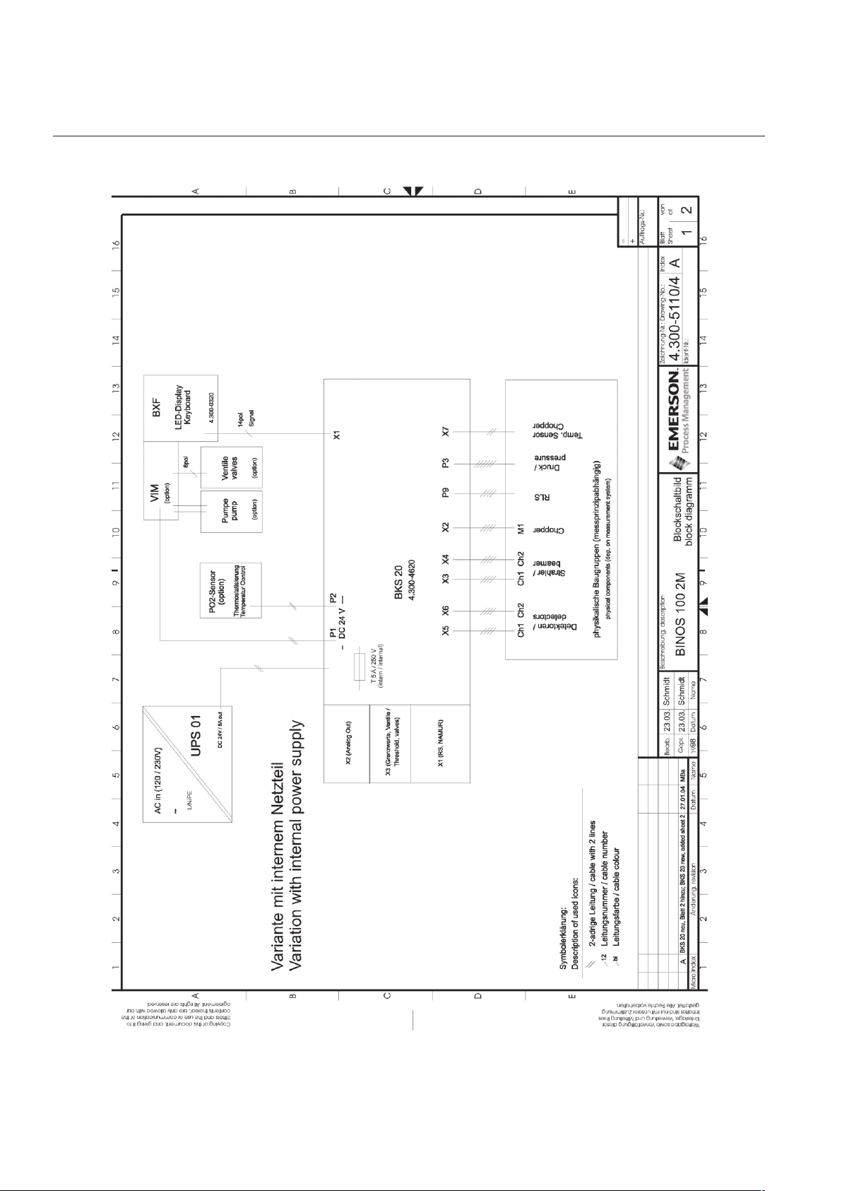
A.2 BINOS® 100 2M Block Diagram
Instruction Sheet
HAS1xE-IS-BKS
10/2004
X19 (+)
X20 (GND)
EMERSON Process Management Manufacturing GmbH & Co. OHGA-2
Page 29

Instruction Sheet
HAS1xE-IS-BKS
10/2004
BKS 20 Upgrade
X19 (+)
X20 (GND)
EMERSON Process Management Manufacturing GmbH & Co. OHG A-3
Page 30

BKS 20 Upgrade
A.3 BINOS® 100 2M for CAT Block Diagram
Instruction Sheet
HAS1xE-IS-BKS
10/2004
X19 (+)
X20 (GND)
EMERSON Process Management Manufacturing GmbH & Co. OHGA-4
Page 31

Instruction Sheet
HAS1xE-IS-BKS
10/2004
A.4 CAT 100 Block Diagram
BKS 20 Upgrade
EMERSON Process Management Manufacturing GmbH & Co. OHG A-5
Page 32
BKS 20 Upgrade
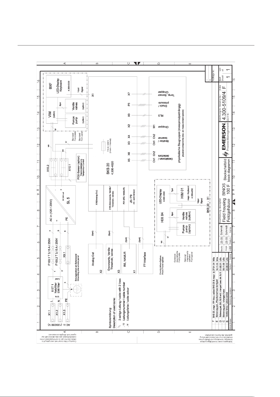
A.5 BINOS® 100 F Block Diagram
X19 (+)
X20 (GND)
Instruction Sheet
HAS1xE-IS-BKS
10/2004
EMERSON Process Management Manufacturing GmbH & Co. OHGA-6
Page 33

BKS 20 Upgrade
EUROPE
Emerson Process Management
Manufacturing GmbH & Co. OHG
Industriestrasse 1
63594 Hasselroth
Germany
T +49 (6055) 884-0
F +49 (6055) 884-209
Internet: www.emersonprocess.de
EUROPE, MIDDLE EAST , AFRICA
Emerson Process Management
Shared Services Limited
Heath Place
Bognor Regis
West Sussex PO22 9SH
England
T +44-1243-863121
F +44-1243-845354
Internet: www.emersonprocess.co.uk
Instruction Sheet
HAS1xE-IS-BKS
10/2004
NORTH AMERICA
Rosemount Analytical Inc.
Process Analytic Division
1201 N. Main St.
Orrville, OH 44667-0901
T +1 (330) 682-9010
F +1 (330) 684-4434
Internet: www.emersonprocess.com
LATIN AMERICA
Emerson Process Management Ltda
Avenida Hollingsworth, 325
Iporanga-SorocabeSP 18087-000
Brazil
T:+55 (152) 38-3788
F:+55 (152) 38-3300
Internet: www.emersonprocess.com.br
ASIA - PACIFIC
Emerson Process Management Asia Pacific Pte Ltd
1 Pandan Crescent
Singapore 128461
Tel +65 6777 8211
Fax +65 6777 0947
Internet: www.ap.emersonprocess.com
© Emerson Process Management Manufacturing GmbH & Co. OHG 2004
 Loading...