

Rosemount BINOS 100 F and MLT 2 Addendum for Pressurized Analyzers in Hazardous Area Applications-6th Ed. Manuals & Guides
Page 1

ATEX Instruction Manual
ETC01035
February 2008
MLT 2 and BINOS® 100 F
Manual Upgrade for Pressurized Analyzers
intended to be used in Hazardous Areas
www.EmersonProcess.com
Page 2

ESSENTIAL INSTRUCTIONS
READ THIS PAGE BEFORE PROCEEDING!
Emerson Process Management (Rosemount Analytical) designs, manufactures and tests
its products to meet many national and international standards. Because these instruments
are sophisticated technical products, you MUST properly install, use, and maintain
them to ensure they continue to operate within their normal specications. The following
instructions MUST be adhered to and integrated into your safety program when installing,
using and maintaining Emerson Process Management (Rosemount Analytical) products.
Failure to follow the proper instructions may cause any one of the following situations
to occur: Loss of life; personal injury; property damage; damage to this instrument; and
warranty invalidation.
• Read all instructions prior to installing, operating, and servicing the product.
• If you do not understand any of the instructions, contact your Emerson Process
Management (Rosemount Analytical) representative for clarication.
• Follow all warnings, cautions, and instructions marked on and supplied with the
product.
• Inform and educate your personnel in the proper installation, operation, and
maintenance of the product.
• Install your equipment as specied in the Installation Instructions of the
appropriate Instruction Manual and per applicable local and national codes.
Connect all products to the proper electrical and pressure sources.
• To ensure proper performance, use qualied personnel to install, operate, update,
program, and maintain the product.
• When replacement parts are required, ensure that qualied people use replacement
parts specied by Emerson Process Management (Rosemount Analytical).
Unauthorized parts and procedures can affect the product’s performance, place the
safe operation of your process at risk, and VOID YOUR WARRANTY. Look-alike
substitutions may result in re, electrical hazards, or improper operation.
• Ensure that all equipment doors are closed and protective covers are in place,
except when maintenance is being performed by qualied persons, to prevent
electrical shock and personal injury.
The information contained in this document is subject to change without notice.
6th edition 2008/02
5th edition 2007/09
Emerson Process Management
GmbH & Co. OHG
Industriestrasse 1
D-63594 Hasselroth
Germany
T +49 (0) 6055 884-0
F +49 (0) 6055 884-209
Internet: www.EmersonProcess.com
Original Instruction Manual for the purpose
of the European Directive 94/9/EC.
Page 3

ATEX Instruction Manual
ETC01035
02/2008
MLT 2 / BINOS 100 F
Ta b l e o f Co n T e n T s
PREAMBLE ..........................................................................................................................S-1
Denitions
Symbols on or inside the instrument
Symbols used in this manual
Terms used in this manual .................................................................................................S-4
Safety instructions
CHAPTER 1 Technical Description 1-1
1.1 Application and Principle of Operation ...............................................................1-1
1.2 Description of Pressurization System .................................................................1-4
1.3 Technical Data ........................................................................................................1-5
1.3.1 Installation Site ...................................................................................................1-5
1.3.2 Explosion Protection..........................................................................................1-5
1.3.3 Electrical and Mechanical Data .........................................................................1-6
1.3.4 Pressurization Gas and Sample Gas Conditions ............................................1-7
1.3.5 Purge Gas Conditions ........................................................................................1-8
1.3.6 Differential Pressure Monitoring .......................................................................1-8
1.3.7 Infallible Containments ......................................................................................1-8
1.3.8 Nameplate Label .................................................................................................1-9
1.3.9 Equivalent Safety Devices ...............................................................................1-10
1.4 Additional Safety Measures ................................................................................ 1-11
............................................................................................................................S-1
................................................................................S-2
.............................................................................................S-3
..............................................................................................................S-6
CHAPTER 2 Installation 2-1
2.1 General....................................................................................................................2-2
2.2 Installing the Intrument .........................................................................................2-2
2.3 Dimensions.............................................................................................................2-3
2.4 Connecting Sample and Protective Gases ..........................................................2-7
2.4.1 Instructions for Handling Flammable Gases ...................................................2-7
2.4.2 MLT 2 Gas Flow Diagrams ................................................................................. 2-9
2.4.2.1 For Nonammable or Flammable Gases diluted below 1/4 LEL ................2-9
2.4.2.2 For Nondiluted Flammable Gases ..............................................................2-10
2.4.3 BINOS® 100 F Gas Flow Diagrams .................................................................. 2-12
2.4.3.1 For Nonammable or Fammable Gases diluted below 1/4 LEL ...............2-12
2.4.3.2 For Nondiluted Flammable Gases ..............................................................2-13
2.5 Adjusting the Pressurization System ................................................................2-15
2.6 Special Instructions .............................................................................................2-15
2.7 Electrical Connections ........................................................................................2-16
TOC-1Emerson Process Management GmbH & Co. OHG
1 Techn. Description
Page 4

TOC-2 Emerson Process Management GmbH & Co. OHG
MLT 2 / BINOS 100 F
ATEX Instruction Manual
ETC01035
02/2008
Table of Contents
2.7.1 Cable Gland Assembly Instruction for Shielded Cables ..............................2-17
2.7.2 Signal Inputs and Outputs ...............................................................................2-17
2.7.3 Category 2 Equipment Mains Connection .....................................................2-18
2.7.4 Power Connection Category 3 Analyzer ........................................................2-19
2.7.4.1 Pressurization Control Unit .........................................................................2-20
CHAPTER 3 Startup 3-1
3.1 Final Check .............................................................................................................3-1
3.2 Switching On ..........................................................................................................3-2
3.2.1 Category 2 System .............................................................................................3-2
3.2.2 Category 3 System .............................................................................................3-2
CHAPTER 4 Maintenance 4-1
4.1 Routine Tests in General .......................................................................................4-2
4.1.1 Routine Tests Interval ....................................................................................... 4-2
4.1.2 Visual Inspections ..............................................................................................4-2
4.1.3 Close Examination .............................................................................................4-2
4.1.4 Detail Examination ............................................................................................4-2
4.2 Routine Tests .........................................................................................................4-3
4.2.1 Gasanalyzer, Analytical Function .....................................................................4-3
4.2.2 Gasanalyzer, Ex Protection ...............................................................................4-3
4.2.3 Differential Pressure Switch (Option) ...............................................................4-3
4.2.4 Pressurization System andother accessories .................................................4-3
4.2.5 Differential Pressure Switch ..............................................................................4-4
4.2.5.1 Preparation .....................................................................................................4-4
4.2.5.2 Differential Pressure Switch Test .................................................................4-5
4.2.5.3 Removal of Modications ..............................................................................4-5
4.3 Tests after Modication or Repair ........................................................................4-6
4.3.1 Analyzer Housing ...............................................................................................4-6
4.3.1.1 Preparation .....................................................................................................4-6
4.3.1.2 Overpressure Test ..........................................................................................4-7
4.3.1.3 Leak Test .........................................................................................................4-7
4.3.1.4 Removal of Modications ..............................................................................4-7
4.4 Troubleshooting .....................................................................................................4-8
4.4.1 Pressurization System Not Activated ..................................................................4-8
Page 5

TOC-3Emerson Process Management GmbH & Co. OHG
1 Techn. Description
MLT 2 / BINOS 100 F
ATEX Instruction Manual
ETC01035
02/2008
Table of Contents
APPENDIX A-1
A.1 EC Declarations of Conformity .............................................................................A-2
A.1.1 Category 2 Equipment .......................................................................................A-2
A.1.2 Category 3 Equipment .......................................................................................A-4
A.2 EC Type Examination Certicate ..........................................................................A-6
A.3 Manufacturer´s Declaration ................................................................................A-13
A.4 Circuit Diagrams, Cat. 2 Equipment ...................................................................A-14
A.4.1 MLT 2, single .....................................................................................................A-14
A.4.2 MLT 2, dual ........................................................................................................A-18
A.4.3 BINOS® 100 F ....................................................................................................A-22
A.5 Circuit Diagrams, Cat. 3 Equipment ...................................................................A-24
A.5.1 MLT 2, single .....................................................................................................A-24
A.5.2 MLT 2, dual ........................................................................................................A-28
A.5.3 BINOS® 100 F ....................................................................................................A-32
In d e x o f fI g u r e s
Fig. 1-1: Analyzer with Category 2 Pressurization System .......................................................................1-2
Fig. 1-2: Analyzer with Category 3 Pressurization System .......................................................................1-3
Fig. 1-3: Nameplate Label Details ................................................................................................................1-9
Fig. 2-1: Cat. 3 Single Enclosure Analyzer (Dimensions in mm) ..............................................................2-3
Fig. 2-2: Cat. 3 Dual Enclosure Analyzer (Dimensions in mm) .................................................................2-4
Fig. 2-3: Cat. 2 Single Enclosure Analyzer (Dimensions in mm) ..............................................................2-5
Fig. 2-4: Cat. 2 Dual Enclosure Analyzer (Dimensions in mm) .................................................................2-6
Fig. 2-3: Single and installed 8 ame arrestors ........................................................................................2-8
Fig. 2-6: Mains Terminals Inside Analyzer ................................................................................................2-19
Fig. 2-7: Mains Terminals Inside Control Unit ..........................................................................................2-20
Fig. 3-1: Cable gland sealing plug ...............................................................................................................3-1
Fig. 3-2: Cable gland hexagon socket screw sealing plug ......................................................................3-1
Fig. 4-1: Setup for Differential Pressure Switch Tests ..............................................................................4-5
Fig. 4-2: Setup for Enclosure Tests .............................................................................................................4-7
Page 6

MLT 2 / BINOS 100 F
ATEX Instruction Manual
ETC01035
02/2008
Table of Contents
TOC-4 Emerson Process Management GmbH & Co. OHG
Page 7

ATEX Instruction Manual
ETC01035
02/2008
MLT 2 / BINOS 100 F
PREAMBLE
This instruction manual provides information about installing, operating and maintaining/servicing pressurized BINOS
100 F and MLT 2 series gas analyzers in hazardous
(classied) areas and shall be read in conjunction with the standard analyzer instruction
manual only!
This instruction manual covers BINOS
100 F and MLT 2 series gas analyzers variations and
therefore may describe congurations and/or options not part of your specic analyzer.
DEFINITIONS
The following denitions apply to WARNINGS, CAUTIONS and NOTES found throughout
this publication.
Highlights an operation or maintenance procedure, practice, condition,
statement, etc. which, if not strictly observed, could result in injury, death,
or long-term health hazards of personnel.
Safety Instructions
Highlights an operation or maintenance procedure, practice, condition,
statement, etc. which, if not strictly observed, could result in minor or
moderate injury or damage to or destruction of equipment, or loss of
effectiveness.
NOTE
Highlights an essential operating procedure, condition or statement.
S-1Emerson Process Management GmbH & Co. OHG
Page 8

S-2 Emerson Process Management GmbH & Co. OHG
MLT 2 / BINOS 100 F
ATEX Instruction Manual
ETC01035
02/2008
SYMBOLS ON OR INSIDE THE INSTRUMENT
This symbol appearing on or inside the
instrument ...
... signals
hazardous voltages are likely to be present.
Covers should only be removed when power
is removed from the equipment — and then by
trained service personnel only.
hot surfaces are likely to be present. Covers
should only be removed by trained service personnel when power is removed from the equipment. Certain surfaces may remain hot to the
touch.
more detailled information and instructions are
required and available: Read the instruction
manuals.
Page 9

S-3Emerson Process Management GmbH & Co. OHG
Safety Instructions
MLT 2 / BINOS 100 F
ATEX Instruction Manual
ETC01035
02/2008
SYMBOLS USED IN THIS MANUAL
Where one or more of the following symbos appear in this instruction manual, carefully read the
given informations and instructions!
Observe the given warnings and instructions to avoid risks!
Where this symbol appears in the manual... ... information is provided about
hazardous voltages likely to be present
high temperatures likely to be present
hazards of explosion likely to be present
toxic substances likely to be present
substances harmful to health likely to be
present
how to handle heavy instruments
electronics components sensitive to electrostatic
discharge
when it is necessary to disconnect equipment
from mains
essential procedures or conditions to be observed.
Also this symbol may mark an important statement to ensure proper measuring conditions.
Page 10

S-4 Emerson Process Management GmbH & Co. OHG
MLT 2 / BINOS 100 F
ATEX Instruction Manual
ETC01035
02/2008
TERMS USED IN THIS MANUAL
ATEX
Directive 94/9/EC, commonly called the
ATEX („Atmosphères Explosibles“) products
directive.
Area Classication
Zone 1
Where ignitable concentrations of ammable
gases can exist some of the time under normal operating conditions.
(A guideline value [not part of a standard ] is
10 to 1.000 hours per year.)
Equipment to be used in Zone 1 has to be
classied Category 2.
Zone 2
Where ignitable concentrations of ammable
gases are not likely to exist under normal
operating conditions.
(A guideline value [not part of a standard ] is
less than 10 hours per year.)
Equipment to be used in Zone 2 has to be
classied Category 3.
Containment System
The part of the analyzer containing the gas
that may constitute an internal source of release.
Explosive Gas(es)
Flammable gases and gas mixtures of a
concentration within the explosion limits and
present in mixture with air.
Flammable Gas(es)
Gases and gas mixtures are assigned to be
ammable if they might become ignitable
when in a mixture with air.
Dilution
The continuous supply of a protective gas,
after purging, at such a rate that the con-
centration of a ammable mixture inside the
pressurized enclosure is maintained at a
value outside the explosive limits except in a
dilution area.
External Explosion Protection
The „External explosion protection“ serves to
prevent penetration of explosive gas mixtures into the analyzer enclosure. In addition it
avoids ignition on the surface. For this reason
the analyzer is purged with protective gas and
held at an internal overpressure compared to
the surrounding atmosphere.
Page 11

S-5Emerson Process Management GmbH & Co. OHG
Safety Instructions
MLT 2 / BINOS 100 F
ATEX Instruction Manual
ETC01035
02/2008
Terms used in this manual
Internal Explosion Protection
The „Internal explosion protection“ serves
to prevent ignition of gas being present in
the analyzer’s Containment System (CS;=
sample gas path).
Dependent on the gas composition several
options are available:
None required (if gas is noncombustible),
dilution by purge gas or/and internal overpressure of the analyzer’s enclosure compared
to the CS.
Lower Explosion Limit (LEL)
Volume ratio of ammable gas in air below
which an explosive gas atmosphere will not
be formed: the mixture of gas and air lacks
sufcient fuel (gas) to burn.
Protective Gas
Air or inert gas used for purging and maintaining an overpressure and, if required, dilution.
Purge mode „Leakage Compensation“
In EEx p „leakage compensation mode“ just
as much protective gas is used to hold an
overpressure of > 1 mbar compared to atmospheric.
Pre-Purging
The pre-purging phase serves to remove any
combustible gas out of the analyzer’s enclosure prior to switching on the analyzer. During
this time the housing is purged with 5 times
its own volume.
Purge mode „Continuous Flow“
In EEx p „continuous ow mode“ the protec-
tive gas ows with higher rates through the
enclosure. Flow rates are calculated to hold
an overpressure of > 1 mbar compared to
atmospheric.
Upper Explosion Limit (UEL)
Volume ratio of ammable gas in air above
which an explosive gas atmosphere will not
be formed: the mixture of gas and air is too
rich in fuel (decient in oxygen) to burn.
Page 12

S-6 Emerson Process Management GmbH & Co. OHG
MLT 2 / BINOS 100 F
ATEX Instruction Manual
ETC01035
02/2008
SAFETY INSTRUCTIONS
INTENDED USE STATEMENT
Emerson series gas analyzers described herein are intended to be used as analyzers for
industrial purposes. They must not be used in medical, diagnostic or life support appli-
cations nor as safety devices, and no independent agency certications or approvals are
to be implied as covering such applications!
SAFETY SUMMARY
If this equipment is used in a manner not specied in these instructions, protective systems may be impaired.
AUTHORIZED PERSONNEL
To avoid explosions, loss of life, personal injury and damage to this equipment and on-site
property, do not operate or service this instrument before reading and understanding this
instruction manual and receiving appropriate training.
ADDITIONAL LITERATURE
This manual covers aspects specic for using pressurized BINOS
gas analyzers analyzers in hazardous (classied) areas, only.
To install, start-up, operate and maintain/service the instrument in a safe manner it is
MANDATORY to read all additional instruction manuals shipped together with the instrument!
The following instruction manuals are available and/or referenced within this manual at
hand and, depending on your system´s conguration, shipped with your analyzer:
90002929 MLT Hardware instruction manual
HAS3xE-IM-SW39 MLT Software instruction manual (rev. 3.9.x or later)
HAS1xE-IM-HS BINOS 100 series instruction manual
HASICE-IM-H Infallible Containment instruction manual
User´s Manual F 850 S Zone 1 Pressurized Enclosure System User´s Manual
User´s Manual F 840 Zone 2 Pressurized Enclosure System User´s Manual
SAVE ALL INSTRUCTIONS FOR FUTURE USE!
Contact your local service center or sales ofce when missing documents.
100 F and MLT 2 series
Page 13

S-7Emerson Process Management GmbH & Co. OHG
Safety Instructions
MLT 2 / BINOS 100 F
ATEX Instruction Manual
ETC01035
02/2008
Safety Instructions
EXPLOSION HAZARD
Read all instruction manuals (including versions for auxiliary equipment)
before installing this instrument!
Violating safety instruction can cause explosion and/or injury, death, or
long-term health hazards of personnel!
HEAVY INSTRUMENT
The analyzer to which this manual relates, intended to be wall mounted
and/or outdoor installed, weighs up to approx. 40 kg, depending on included
options!
Use two people and/or suitable tools for transportation and lifting these
instruments!
Take care to use anchors and bolts specied to be used for the weight of
the units!
Take care the wall or stand the unit is intended to be installed at is solid
and stable to hold the units!
Don´t use the attached pressurization unit´s components as a transportation
handle!
EXPLOSION HAZARD
Operating an open instrument or an instrument with disabled pressurization
system for maintenance requires a hot work permit to be issued to ensure,
the surrounding atmosphere is safe to operate the instrument!
Using the bypass key is permitted for maintenance only!
Page 14

S-8 Emerson Process Management GmbH & Co. OHG
MLT 2 / BINOS 100 F
ATEX Instruction Manual
ETC01035
02/2008
Installing and wiring this instrument must comply with all relevant national
legislative requirements and regulations.
Consider all safety instructions within this on hand manual and all associated analyzer instruction manuals!
Safety Instructions
EXPLOSION HAZARD
POSSIBLE EXPLOSION HAZARD
Do NOT operate the instrument with doors or covers open! This is permitted
only when no hazardous atmosphere is present!
Depending on the local regulation, this may require a competent hot work
supervisor to issue a hot work permit.
EXPLOSIONS HAZARD
When installing optional ame arrestors take care to properly x the tube
ttings for leak free installation!
Fittings not tight enough (especially those at the enclosure side of the
ame arrestors) may increase safety of the whole equipment and can cause
explosions!
Read and follow the accompanying ame arrestor´s instructions!
The operator should take into account the possibility of air penetrating
the containment system through a leak and the formation of explosive
atmosphere. Additional safety measures may be required for safe
operation!
Page 15

S-9Emerson Process Management GmbH & Co. OHG
Safety Instructions
MLT 2 / BINOS 100 F
ATEX Instruction Manual
ETC01035
02/2008
Safety Instructions
ELECTRICAL SHOCk HAZARD
Installation and connecting power and signal cables are subject to qualied
personnel only taking into account all applicable standards and legislative
requirements! Especially the standard EN 60079-14 „Electrical Installations
in Hazardous Areas“ and all related standards have to be observed.
Failure to follow may cause warranty invalidation, property damage and/or
personal injury or death!
Installation of these instruments is subject to qualied personnel only,
familiar with the resulting potential risks! Instruments providing screw
terminals for electrical connections may require working near live part!
Analyzers described in this manual do not provide a power switch!
A power switch or circuit breaker (complying with IEC 60947-1/-3) has to be
provided in the building installation. This switch has to be installed near
by analyzer, must be easily operator accessible and has to be assigned as
disconnector for the analyzer.
Disconnect instruments with screw terminals from power when working at
power terminals (pull power plug or operate power switch/ circuit breaker
in building installation)!
The analyzers provide a protective earth terminal. To prevent electrical
shock hazards the instruments must be connected to a protective earth.
Therefore the instruments must be connected to power by using a three
wire power cable with earth conductor!
Any interruption of the earth connector inside or outside the instrument
or disconnecting the earth terminal may cause potential electrical shock
hazzard!
The analyzers do not provide a power switch and are operable when connected to power.
Page 16

S-10 Emerson Process Management GmbH & Co. OHG
MLT 2 / BINOS 100 F
ATEX Instruction Manual
ETC01035
02/2008
Installing this instrument requires opening the enclosure and working at
the open instrument. This is permitted only when no hazardous atmosphere
is present!
Depending on the local regulation, this may require a competent hot work
supervisor to issue a hot work permit.
Safety Instructions
EXPLOSION HAZARD
ELECTRICAL SHOCk HAZARD
Verify the power supply at installation site meets the specication given on
the analyzer´s nameplate label, before installing the instrument!
Verify power cables are disconnected and/or instrument is de-energized
prior to working at the terminals!
Verify the power cord is layed with a distance of at least 1 cm (0.5“) to any
signal cable to ensure proper insulation from signal circuits!
ELECTRICAL SHOCk HAZARD
Before completing the electrical connection of the instrument, verify cables
are inserted and connected in proper way!
Ensure the earthing conductor (protective earth; PE) is connected!
Page 17

S-11Emerson Process Management GmbH & Co. OHG
Safety Instructions
MLT 2 / BINOS 100 F
ATEX Instruction Manual
ETC01035
02/2008
Safety Instructions
EXPLOSION HAZARD
When the analyzer is out of order or if the pressurization unit shuts off
due to a failure all non-intrinsically safe inputs and outputs connected to
external equipment MUST be shut off too!
This ensures that no hazardous voltages are present within the analyzer
enclosure when not pressurized.
HIGH PRESSURE HAZARD
The maximum inlet purge gas pressure at the inlet valve must not exceed
6900 hPa (6,9 bar)!
Higher pressure may damage the analyzer enclosure in case of failure of
the inlet valve!
Take care to externally limit the maximum inlet purge gas pressure!
Page 18

ATEX Instruction Manual
ETC01035
02/2008
CHAPTER 1
Technical Description
1.1 Application and Principle of Operation
MLT 2 / BINOS 100 F
The gas analyzers of type BINOS 100 F and
MLT 2 are intended to measure gas components within gas mixtures. In combination with
an appropriate certied pressurization system
(protection method „Pressurized Enclosure“
Ex p) they can be installed and operated in
hazardous areas of Zone 2.
Pressurization acts as external explosion
protection and prevents external explosive
atmosphere to penetrate into the analyzer
by holding the enclosure at an overpressure
compared to the surrounding
The type of purge system used varies dependent on the area where the analyzer is
intended to be installed. Both systems offer
two modes of operation:
• Ex p with continuous ow
and
• Ex p with leakage compensation.
Dependent on the sample gas composition it
may be necessary to take care of internal explosion protection which refers to the sample gas
path (containment system) in the analyzer.
One has to differentiate between the following
measurement applications:
• Nonammable gases and gas mixtu-
res below the LEL: It must be ensured
that the sample gas in the containment
system always remains below the lower
explosive limit!
• Flammable gases and gas mixtures
may be analyzed using an analyzer with
pressurization method „leakage compen sation“ when the sample gas is diluted
below ¼ LEL outside the analyzer, so the
resulting sample gas is to be categorized
„nonflammable“. The diluting system
must ensure that the gas in the containment system always remains below ¼
LEL.
• Flammable gases and gas mixtures
may be analyzed using an analyzer
with pressurization method „leakage
compensation“ or „continuous flow“
when the analyzer enclosure has an
internal overpressure of > 50 Pa above
the pressure in the containment system.
To ensure this condition a differential
pressure switch is used and connected between containment system and
analyzer enclosure, activating an alarm
contact in case the pressure decreases
below the level of 50 Pa. For Category 2
instruments the purging unit disconnects
the analyzer from it’s power supply and
starts a prepurge phase. For Category 3
instruments the operator has to ensure
the alarm signal is interpreted in a proper
way. If more than one switch is needed
because more than one ammable gas is
supplied to the analyzer, the contacts of
these switches have to be connected in
series. Purge medium may be inert gas
or air.
Depending on the measured gas and
methode infallible containments may be
used, so differential pressure switches
become redundant.
1 Techn. Description
1-1Emerson Process Management GmbH & Co. OHG
Page 19

1-2 Emerson Process Management GmbH & Co. OHG
MLT 2 / BINOS 100 F
ATEX Instruction Manual
ETC01035
02/2008
1.1 Application and Principle of Operation
1 2 3 4 5 1 2 3 4 5687 7
1 Purge gas inlet
2 Pressure relief valve (on bottom or optional on top side)
3 Purge gas outlet
4 Control unit
5 Analzer front door
6 Analyzer physics door (dual enclosure MLT 2 only)
7 Cable inlets
8 Gas ttings
Fig. 1-1: Analyzer with Category 2 Pressurization System
Page 20

1-3Emerson Process Management GmbH & Co. OHG
1 Techn. Description
MLT 2 / BINOS 100 F
ATEX Instruction Manual
ETC01035
02/2008
1.1 Application and Principle of Operation
1 2 3 4 5 1 2 3 4 5687 7
1 Purge gas inlet
2 Pressure relief valve (on bottom or optional on top side)
3 Purge gas outlet
4 Control unit
5 Analzer front door
6 Analyzer physics door (dual enclosure MLT 2 only)
7 Cable inlets
8 Gas ttings
Fig. 1-2: Analyzer with Category 3 Pressurization System
Page 21

1-4 Emerson Process Management GmbH & Co. OHG
MLT 2 / BINOS 100 F
ATEX Instruction Manual
ETC01035
02/2008
1.2 Description of Pressurization System
1.2 Description of Pressurization System
The intention of a pressurized analyzer is to
keep out of the instrument a surrounding potentially explosive atmosphere by providing
an internal overpressure. The pressurization
system consists of a gas inlet valve, control unit
with micro processor and a bypass switch (Cat
2 only). The control unit monitors all relevant
parameters (pre-purge phase, purge medium
flow, internal overpressure, and more) and
ensures safe operation.
Category 2 analyzers, to be installed in Zone 1
are automatically pre-purged before the power
supply is activated. This ensures a potentially
explosive atmosphere is ushed out. The pre-
purge phase is controlled by the micro processor
unit, which also activates the power supply for
the analyzer when the pre-purge phase has
elapsed or disconnects the analyzer from power
supply in case of failure. It´s internal design has
redundant components to ensure safe operation
even in case of 1 failure.
The main difference of a Category 3 pressu-
rization unit for Zone 2 installation is, that this
unit does not control the analyer´s power supply (e.g. in case of a failure the analyzer is not
disconnected), pre-purging is only optional and
the internal controller design is not as redundant
(safe operation without failure). If an infallible
containment is available for the specic appli-
cation, it can be used for measuring ammable
gases. But, measuring ammable gases utilizing
a differential pressure switch is not permitted: In
this case a Zone 1 instrument has to be used.
The different gaspath designs for measuring
ammable or non-ammable gases also inuence the intruments operation parameters:
Measuring non-ammable gases:
The pressurization system provides an internal
overpressure of 14 mbar. The acceptable samp-
le gas pressure complies with the specications
of an analyzer for non-hazardous (general purpose) areas.
Measuring ammable gases utilizing a diffe-
rential pressure switch:
The internal overpressure is adjusted to
14 mbar. The opertor has to ensure the gas
pressure (sample gas, calibration gases) inside
the containment system remains below 12 mbar,
due to the fact that there is a differential pressure switch installed in each gas path containing
ammable gas. Limiting the gas pressure ensures the pressure inside the instrument is always
at minimum 50 Pa (0,5 mbar) above the con-
tainment pressure. This conguration ensures
that in case of a gas path leak ammable gas
cannot enter the analyzer enclosure.
In case the pressure difference is less than the
given values (due to a failure), the control unit
disconnects the analyzer power supply and
starts pre-purging.
EXPLOSION HAZARD
The operator has to ensure that in case the analyzer is disconnected from
its power supply, applied external signals are disconnected, too, if they are
not intrinsically safe!
Page 22

1-5Emerson Process Management GmbH & Co. OHG
1 Techn. Description
MLT 2 / BINOS 100 F
ATEX Instruction Manual
ETC01035
02/2008
1.3 Technical Data
1.3 Technical Data
1.3.1 Installation Site
Hazardous area (dependent on pressurization system): Zone 1, Gas or Zone 2, Gas
Permissible ambient temperature range: -20 °C to +40 °C
Permissible ambient storage temperature range: -20 °C to +60 °C
Humidity (non condensing): < 90 % r. h. at +20 °C
< 70 % r. h. at +40 °C
Pollution degree: 2
Installation category: II
Altitude: 0 to (2000 m) above sea level
Surrounding atmosphere Analyzers must not be operated in
corrosive atmosphere.
1.3.2 Explosion Protection
Concepts:
Category 2 :
Category 3:
Temperature class: T4
Analyzer markings:
Options
Infallible containment.
: Intrinsically safe (Ex i) digital, ana-
Pressurized enclosure (Ex px)
with either leakage compensa-
tion mode or continuous ow
Pressurized enclosure (Ex pz)
using simplified purge with
either leakage compensation
mode or continuous ow
dependent on pressurization system
and intended installation site´s
classication (see page 1-9 for
detailled infomation)
log or network outputs.
Intrinsically safe (Ex i) paramagne-
tic Oxygen sensor.
Applicable Standards:
Cat. 2: EN 60079-0 (2004),
EN 60079-2 (2004),
EN 60079-11 (2007)
Cat. 3: EN 60079-0 (2004),
EN 60079-2 (2004),
Page 23

1-6 Emerson Process Management GmbH & Co. OHG
MLT 2 / BINOS 100 F
ATEX Instruction Manual
ETC01035
02/2008
1.3 Technical Data
1.3.3 Electrical and Mechanical Data
For data not listed see the separate analyzer´s
instruction manual.
Power Supply
HAZARD BY WRONG INPUT VOLTAGE !
Applying a rated voltage other than specied on the analyzer´s nameplate
label may cause an explosion, injury or damage to the installation.
Pressurized analyzers for hazardous locations do NOT provide wide range power
supplies! This type of analyzers is always setup for a specic rated input voltage,
see nameplate label!
Ensure the voltage at site of installation meets the rated analyzer input
voltage!
Rated input voltage: 110 V~, 120 V~, 220 V~ or 230 V~,
48 ... 62 Hz
Rated power: 700 VA max
Housing
Weight: approx. up to 40 kg
(depending on analyzer conguration)
Protection class: IP 54 (EN 60529)
(IP65 if purge gas outlet is protected
accordingly, e.g. by a connected pipe)
for outdoor installation
Analyzer must not be exposed to direct
sun light
Gas ttings, except of the pressurization unit: quantity: max. 8
specication: 6/4 mm or 1/4",
stainless steel
Pressurization Unit Specic Data
See separate instruction manual
Page 24

1-7Emerson Process Management GmbH & Co. OHG
1 Techn. Description
MLT 2 / BINOS 100 F
ATEX Instruction Manual
ETC01035
02/2008
1.3 Technical Data
1.3.4 Pressurization Gas and Sample Gas Conditions
Single Enclosure
Application Mode of Operation
Measurement of Pre-purging
ammable gases with Duration: 4 min 6 min
differential pressure
switch Gas ow: 6,8 Nm³/h 9,2 Nm³/h
Maximum
overpressure: 25 mbar 25 mbar
Measuring
Internal overpressure: 14 mbar 14 mbar
Gas ow (leakage
maximum sample gas
pressure: 12 mbar 12 mbar
Measurement of Pre-purging
non-ammable gases Duration: 4 min 6 min
Gas ow: 6,8 Nm³/h 9,2 Nm³/h
Maximum
overpressure: 25 mbar 25 mbar
(Volume: approx. 56 l)
rate): <= 3 l/min (180 l/h) <= 4,5 l/min (270 l/h)
Dual Enclosure
(Volume: approx. 112 l)
Measuring
Internal overpressure: 14 mbar 14 mbar
Gas ow (leakage
rate): <= 3 l/min (180 l/h) <= 4,5 l/min (270 l/h)
maximum sample gas
pressure:
see analyzer instruction manual
Page 25

1-8 Emerson Process Management GmbH & Co. OHG
MLT 2 / BINOS 100 F
ATEX Instruction Manual
ETC01035
02/2008
1.3 Technical Data
1.3.5 Purge Gas Conditions
Purge gas: •Inert gas (e.g. Nitrogen)
•Air (from an ex-free area)
Temperature: As ambient, but min. +20 °C to +35 °C.
Medium has to be dry and free from
dust, oil, corrosive or aggressive
components!
Rated input pressure at inlet of Ex p device: 2000 to 4000 hPa (2 to 4 bar)
Maximum input pressure at inlet of Ex p device: 6900 hPa (6,9 bar)
Minimum internal overpressure of the enclosure: 1 mbar
Maximum internal overpressure of the enclosure
during operation: 25 mbar
1.3.6 Differential Pressure Monitoring
For analyzers connected to ammable gases
(either sample gas or span gas) the operator
needs to ensure that the pressure within the
containment system always remains at minimum 50 Pa below the pressure within the
analyzer enclosure. This ensures that in case
of a leak the ammable gas does not enter
the enclosure.
An additional differential pressure switch must
be provided to monitor the pressure difference. The switch’s electric contact has to be
1.3.7 Infallible Containments
Infallible containments may be used alterna-
tively for measuring ammable gases instead
of using differential pressure monitoring:
Infallible containments are designed and
built using joints made by welding, brazing,
glass to metal sealing, eutectic or comparable
methods. This ensures that the containment
does not have any intentional leakage into
the pressurized enclosure and supersedes
connected to the purge system. In case the
pressure difference decreases below 50 Pa
the contact opens and the purge system shuts
down the analyzer.
The limit of 50 Pa is the lowest permissible
value given by the standards, higher values
are acceptable, too.
Electrical and mechanical connections are
shown in section 2 „Installation“.
the differential pressure switch and the „50 Pa
overpressure condition“ (see 1.3.6).
Infallible containments are currently available
for the measuring principle TC (thermal con-
ductivity). Pls. contact your local sales ofce
for more information.
If your analyzer provides an infallible contain-
ment, see the associated manual for more
information.
Page 26

1-9Emerson Process Management GmbH & Co. OHG
1 Techn. Description
MLT 2 / BINOS 100 F
ATEX Instruction Manual
ETC01035
02/2008
1.3.8 Nameplate Label
1.3 Technical Data
Fig. 1-3: Nameplate Label Details
(example)
Area Description Area Description
The analyzer´s electrical data and serial
number: digits 3 to 5 show manufacturing date („mmy“), e.g. 097 = 09 2007
The maximum gas input pressure to be
applied to the containment system, if the
analyzer is congured to measure ammable
gases
Manufacturer address, CE mark, number of Notied Body for Quality assement and
certication data:
Zone 1 Zone 2
Area classication
Protection concepts
Certicate number
II other than mines
2 Category 2 Equipm. (Zone 1)
G for explosive Gas atmosphere
Ex Explosion protected
[ia] or ia Intrinsically safe output
(depending on type of internal
components)
px Zone 1 pressurization system
IIC Group II, Gas Group C
T4 Temperature Class (135 °C)
LCIE 03 ATEX 6010 X Manufacturers Declaration, not
The measuring channel data (components & ranges)
The purge medium data to be observed
to comply with the certicate, the maxi-
mum leakage ow rate and the volume
of the enclosure
II other than mines
3 Category 3 Equipm. (Zone 2)
G for explosive Gas atmosphere
Ex Explosion protected
[ia] or ia Intrinsically safe output
(depending on type of internal
components)
pz Zone 2 pressurization system
IIC Group II, Gas Group C
T4 Temperature Class (135 °C)
shown on the nameplate label
Page 27

1-10 Emerson Process Management GmbH & Co. OHG
MLT 2 / BINOS 100 F
ATEX Instruction Manual
ETC01035
02/2008
1.3.9 Equivalent Safety Devices
An explosion may result of using a pressurization system other than
recommended by Emerson Process Management!
It is the responsibility of the operator/owner to choose and install such
systems not provided and specied by Emerson Process Management.
In no case Emerson Process Management is held responsible for any
damage, personal injury etc. resulting from choosing different pressurization
systems!
1.3 Technical Data
EXPLOSION HAZARD
In principle it is possible to use other equivalent pressurization systems than described
in this manual, as long as they meet the following requirements:
• Device is ATEX approved
• Adjustable pre-purge phase
• Minimum purge ow rate :
6,8 Nm3/h resp. 9,2 Nm³/h
• Limited purge gas pressure during the pre-
purging phase: < 25 mbar
• Input pressure for purge gas supply:
2 ... 4 bar
Category 2 equipment:
• Relay contacts for all-pole disconnection
of the analyzer from power supply
• Relay contacts for disconnecting additional
external equipment
• Connection facility for bypass key switch,
providing intrinsically safe signal for scanning the key switch
• For units measuring ammable gases,
only:
Connection facility for differential pressure
switch, providing intrinsically safe signal for
scanning the switch.
Page 28

1-11Emerson Process Management GmbH & Co. OHG
1 Techn. Description
MLT 2 / BINOS 100 F
ATEX Instruction Manual
ETC01035
02/2008
1.4 Additional Safety Measures
1.4 Additional Safety Measures
• Exhaust gas lines must end outside the
hazardous area at a safe point. Sample
gas lines may be returned to the sampling
point.
• If gas exhaust lines end within the hazardous area gas inlet and outlet have to be
equipped with ame arrestors.
• The maximum permissible gas pressure
depends on the type of installed measu-
ring principle and classication of gas
(ammable / nonammable). See section
1.3.4 for detailed information.
The maximum inlet purge gas pressure at the inlet valve must not exceed
6900 hPa (6,9 bar)!
Higher pressure may damage the analyzer enclosure in case of failure of
the inlet valve!
Page 29

MLT 2 / BINOS 100 F
ATEX Instruction Manual
ETC01035
02/2008
1-12 Emerson Process Management GmbH & Co. OHG
Page 30

ATEX Instruction Manual
ETC01035
02/2008
Read all instruction manuals (including versions for auxiliary equipment)
before installing this instrument!
Violating safety instruction can cause explosion and/or injury, death, or
long-term health hazards of personnel!
MLT 2 / BINOS 100 F
CHAPTER 2
Installation
EXPLOSION HAZARD
HEAVY INSTRUMENT
The analyzer to which this manual relates, intended to be wall mounted
and/or outdoor installed, weighs up to approx. 40 kg, depending on included
options!
Use two people and/or suitable tools for transportation and lifting these
instruments!
Take care to use anchors and bolts specied to be used for the weight of
the units!
Take care the wall or stand the unit is intended to be installed at is solid
and stable to hold the units!
Don´t use the attached pressurization unit´s components as a transportation
handle!
1 Techn. Description
2-1Emerson Process Management GmbH & Co. OHG
Page 31

2-2 Emerson Process Management GmbH & Co. OHG
MLT 2 / BINOS 100 F
ATEX Instruction Manual
ETC01035
02/2008
2.1 General
2.1 General
Proper function of the instrument requires
proper installation.
Take care to follow all instructions given in this
chapter as well as given in the accompanying
manuals of the safety devices!
2.2 Installing the Intrument
Install the instrument as described in the basic
analyzer instruction manual: Pay attention to
the revised dimensions, due to the attached
pressurization equipment, as shown in gures
2-1 to 2-4.
Ensure there is enough space to install the
equipment.
Page 32

2-3Emerson Process Management GmbH & Co. OHG
1 Techn. Description
MLT 2 / BINOS 100 F
ATEX Instruction Manual
ETC01035
02/2008
2.3 Dimensions
2.3 Dimensions
Basic enclosure
with Cat. 3 Ex pz system
Fig. 2-1: Cat. 3 Single Enclosure Analyzer (Dimensions in mm)
Page 33

2-4 Emerson Process Management GmbH & Co. OHG
MLT 2 / BINOS 100 F
ATEX Instruction Manual
ETC01035
02/2008
Basic enclosure
2.3 Dimensions
with Cat. 3 Ex pz system
Fig. 2-2: Cat. 3 Dual Enclosure Analyzer (Dimensions in mm)
Page 34

2-5Emerson Process Management GmbH & Co. OHG
1 Techn. Description
MLT 2 / BINOS 100 F
ATEX Instruction Manual
ETC01035
02/2008
2.3 Dimensions
Basic enclosure
with Cat. 2 Ex px system
Fig. 2-3: Cat. 2 Single Enclosure Analyzer (Dimensions in mm)
Page 35

2-6 Emerson Process Management GmbH & Co. OHG
MLT 2 / BINOS 100 F
ATEX Instruction Manual
ETC01035
02/2008
Basic enclosure
2.3 Dimensions
with Cat. 2 Ex px system
Fig. 2-4: Cat. 2 Dual Enclosure Analyzer (Dimensions in mm)
Page 36
2-7Emerson Process Management GmbH & Co. OHG
1 Techn. Description
MLT 2 / BINOS 100 F
ATEX Instruction Manual
ETC01035
02/2008
2.4 Connecting Sample and Protective Gases
2.4 Connecting Sample and Protective Gases
After having installed the instrument, connect
the sample gas and protective gas supply
lines according to g. 2-4.
To ensure faultless operation the following
conditions apply:
•
For the pressurization system a minimum protective gas pressure of 2000 bis
4000 hPa (2...4 bar) has to be provided at
the inlet of the gas inlet valve.
2.4.1 Instructions for Handling Flammable Gases
• It is prohibited to supply ammable gases
before the prepurge phase has elapsed.
• To avoid internal release of ammable gas
either
the pressurization system has to be
setup to set the internal pressure of the
enclosure to at minimum 50 Pa above
the containment system pressure(with
a differential pressure monitoring this
condition)
or
an infallible containment has to be used
(if available).
• The pressurization unit is shipped with
congured parameters: E.g. the minimum
internal overpressure for standard applications is set to 1 mbar. Reasonable changes (e.g. increasing values) are permitted,
considering the instructions given in the
pressurization instruction manual and the
data given on the analyzers nameplate
label!
The 50 Pa threshold is specied
by the applicable standards.
It is prohibited to setup lower
values!
HAZARD BY FORMATION OF EXPLOSIVE ATMOSPHERE
The operator should take into account the possibility of air penetrating
the containment system through a leak and the formation of explosive
atmosphere. Additional safety measures may be required for safe
operation!
Page 37

2-8 Emerson Process Management GmbH & Co. OHG
MLT 2 / BINOS 100 F
ATEX Instruction Manual
ETC01035
02/2008
2.4.1 Instructions for Handling Flammable Gases
Flame Arrestor Installation
The analyzers may optionally be provided
with ame arrestors. Use the accompanying
short pipes, designed to allow up to 8 ame
arrestors to be installed to each instrument.
Fig. 2-3: Single and installed 8 ame arrestors
EXPLOSIONS HAZARD
When installing optional ame arrestors take care to x the tube ttings
for leak free installation!
Fittings not tight enough (especially those at the enclosure side of the
ame arrestors) may increase safety of the whole equipment and can cause
explosions!
Read and follow the accompanying ame arrestor´s instructions!
Page 38

2-9Emerson Process Management GmbH & Co. OHG
1 Techn. Description
MLT 2 / BINOS 100 F
ATEX Instruction Manual
ETC01035
02/2008
2-4-2 MLT 2 Gas Flow Diagrams
2-4-2 MLT 2 Gas Flow Diagrams
2-4-2-1 Gas Flow Diagram for Nonammable Gases or
Flammable Gases diluted below 1/4 LEL
Fig. 2-4a
Gas Flow Diagram
Page 39

2-10 Emerson Process Management GmbH & Co. OHG
MLT 2 / BINOS 100 F
ATEX Instruction Manual
ETC01035
02/2008
2-4-2 MLT 2 Gas Flow Diagrams
2-4-2-2 Gas Flow Diagrams for Nondiluted Flammable Gases
Fig. 2-4b
Gas Flow Diagram
Page 40

2-11Emerson Process Management GmbH & Co. OHG
1 Techn. Description
MLT 2 / BINOS 100 F
ATEX Instruction Manual
ETC01035
02/2008
2-4-2 MLT 2 Gas Flow Diagrams
2-4-2-2 Gas Flow Diagrams for Nondiluted Flammable Gases (cont’d)
Fig. 2-4c
Gas Flow Diagram
Page 41

2-12 Emerson Process Management GmbH & Co. OHG
MLT 2 / BINOS 100 F
ATEX Instruction Manual
ETC01035
02/2008
2-4-3 BINOS® 100 F Gas Flow Diagrams
2-4-3 BINOS® 100 F Gas Flow Diagrams
2-4-3-1 Gas Flow Diagram for Nonammable Gases or
Flammable Gases diluted below 1/4 LEL
Fig. 2-4d
Gas Flow Diagram
Page 42

2-13Emerson Process Management GmbH & Co. OHG
1 Techn. Description
MLT 2 / BINOS 100 F
ATEX Instruction Manual
ETC01035
02/2008
2-4-3 BINOS® 100 F Gas Flow Diagrams
2-4-3-2 Gas Flow Diagrams for Nondiluted Flammable Gases
Fig. 2-4e
Gas Flow Diagram
Page 43

2-14 Emerson Process Management GmbH & Co. OHG
MLT 2 / BINOS 100 F
ATEX Instruction Manual
ETC01035
02/2008
2-4-3 BINOS® 100 F Gas Flow Diagrams
2-4-3-2 Gas Flow Diagrams for Nondiluted Flammable Gases (cont’d)
Fig. 2-4f
Gas Flow Diagram
Page 44

2-15Emerson Process Management GmbH & Co. OHG
1 Techn. Description
MLT 2 / BINOS 100 F
ATEX Instruction Manual
ETC01035
02/2008
2.5 Adjusting the Pressurization System
2.5 Adjusting the Pressurization System
The pressurization unit is shipped with congured parameters: E.g. the minimum internal overpressure for standard applications
is set to 1 mbar. Reasonable changes (e.g.
increasing values) are permitted, considering
the instructions given in the pressurization
instruction manual and the data given on the
analyzers nameplate label!
2.6 Special Instructions
The internal purge gas path
must not be modied!
Category 2 Equipment
Analyzers for installation in Zone 1 provide a
front door switch to bypass the pressurization unit. This allows to maintain an open and
operating analyzer.
After maintenace is done, ensure the switch
is deactivated by setting it to „0“ and pull out
the key!
All parameters must comply with the data gi-
ven in the EC Type Examination Certicate!
As a consequence some parameters may
not to be changed, for example, the duration
of the pre-purge phase, which is adjusted to
ensure proper ushing of the enclosure.
The pressurization unit´s M-Code, factory set
to „0001“, has to be replace by an individual
code.
The pressurization unit´s bypass code, factory
set to „0002“, has to be replace by an individual code, not „0“.
See the accompanying pressurization instruction manual for detailled instruction
on how to change the codes.
EXPLOSION HAZARD
Operating an open instrument or an instrument with disabled pressurization
system for maintenance requires a hot work permit to be issued to ensure,
the surrounding atmosphere is safe to operate the instrument!
Using the bypass key is permitted for maintenance only!
Page 45

2-16 Emerson Process Management GmbH & Co. OHG
MLT 2 / BINOS 100 F
ATEX Instruction Manual
ETC01035
02/2008
2.7 Electrical Connections
ELECTRICAL SHOCk HAZARD
Installation and connecting power and signal cables are subject to qualied
personnel only taking into account all applicable standards and legislative
requirements! Especially the standard EN 60079-14 „Electrical Installations
in Hazardous Areas“ and all related standards have to be observed.
Failure to follow may cause warranty invalidation, property damage and/or
personal injury or death!
2.7 Electrical Connections
Installation of these instruments is subject to qualied personnel only,
familiar with the resulting potential risks! Instruments providing screw
terminals for electrical connections may require working near live part!
Analyzers described in this manual do not provide a power switch!
A power switch or circuit breaker (complying with IEC 60947-1/-3) has to be
provided in the building installation. This switch has to be installed near
by analyzer, must be easily operator accessible and has to be assigned as
disconnector for the analyzer.
Disconnect instruments with screw terminals from power when working at
power terminals (pull power plug or operate power switch/ circuit breaker
in building installation)!
The analyzers provide a protective earth terminal. To prevent electrical
shock hazards the instruments must be connected to a protective earth.
Therefore the instruments must be connected to power by using a three
wire power cable with earth conductor!
Any interruption of the earth connector inside or outside the instrument
or disconnecting the earth terminal may cause potential electrical shock
hazzard!
The analyzers do not provide a power switch and are operable when connected to power.
Page 46

2-17Emerson Process Management GmbH & Co. OHG
1 Techn. Description
MLT 2 / BINOS 100 F
ATEX Instruction Manual
ETC01035
02/2008
2.7.1 Cable Gland Assembly Instruction for Shielded Cables
2.7.1 Cable Gland Assembly Instruction for Shielded Cables
1. Strip the cabel insulation
2. Uncover the shielding
3. Feed cable through
gland nut and into
xing element
5. Stick the fixing element into the neck
and x the gland
4. Put the shielding net
over the element
the way that it covers the o-ring 2 mm
(0.08 in).
2.7.2 Signal Inputs and Outputs
Signal inputs and outputs by default are NOT
intrinsically safe!
Optional elements may be provided for installation on internal DIN rails, to convert
EXPLOSION HAZARD
When the analyzer is out of order or if the pressurization unit shuts off
due to a failure all non-intrinsically safe inputs and outputs connected to
external equipment MUST be shut off too!
non-intrinsically safe signals to intrinsically
safe signals. Es können jedoch auf der im
Gerät vorhan
This ensures that no hazardous voltages are present within the analyzer
enclosure when not pressurized.
Page 47

2-18 Emerson Process Management GmbH & Co. OHG
MLT 2 / BINOS 100 F
ATEX Instruction Manual
ETC01035
02/2008
2-7-3 Category 2 Equipment
2-7-3 Category 2 Equipment Mains Connection
The mains power line cord has to be connected to the pressurization control unit,
terminals 16, 18 and PE (g. 2-4).
Verify that the mains voltage
at the point of installation
meets the analyzer nominal
voltage!
Terminal 16
Terminal 18
PE terminal
Fig. 2-5
Terminal location inside control unit
Page 48

2-19Emerson Process Management GmbH & Co. OHG
1 Techn. Description
MLT 2 / BINOS 100 F
ATEX Instruction Manual
ETC01035
02/2008
2.7.4 Power Connection Category 3 Analyzer
2.7.4 Power Connection Category 3 Analyzer
We recommend to supply Analyzer and pressurization control unit with separate power
cables.
This enables to supply the control unit independentlys if in special application pre-purging the analyzer is required.
Installation instructions for mains termi-
nals:
Strip the cable 8 - 9 mm, press the pushbutton,
insert the cable and release the pushbutton.
Verify that the mains voltage at
the point of installation meets
the analyzer´s nominal voltage!
Fig. 2-6: Mains Terminals Inside Analyzer
EMV mains lter
Mains terminals
Page 49

MLT 2 / BINOS 100 F
2.7.4 Power Connection Category 3 Analyzer
2.7.4.1 Pressurization Control Unit
ATEX Instruction Manual
ETC01035
02/2008
Remove the control unit´s cover to connect
the mains cable (Fig. 2-7):
• Line to terminal 9
• Neutral to terminal 7
• Protective Earth (PE) to the terminal at
the internal rear side of the housing.
In case of pressurization failure
the analyzer will not be switched off!
Automatic switch off in case of
pressurization failure requires
an external switch (relay), additional wiring and use of alarm
contacts!
See the associated instruction
manual for more information.
Re-install the cover!
Terminal 9 (Line)
Terminal 7 (Neutral)
PE terminal
Fig. 2-7: Mains Terminals Inside Control Unit
2-20 Emerson Process Management GmbH & Co. OHG
Page 50

ATEX Instruction Manual
ETC01035
02/2008
Startup can only be done properly by personnel being familiar with the
contents of all applicable manuals and related instructions!
Especially the warnings provided in the documentation have to be
observed!
3.1 Final Check
MLT 2 / BINOS 100 F
CHAPTER 3
Startup
3 Startup
DANGER TO LIFE, EXPLOSION HAZARD
Startup personnel has to make sure that
the analyzer and the related pressurization
system have been setup as described in
chapter 2 and all covers and doors are closed
and xed.
All unused cable glands need to be sealed
using the supplied approved sealing plug
(part no. ETC00791; g. 3-1)
Unused cable gland openings in the enclosure need to be covered using a special screw
(part no. ETC 000790; g. 3-2).
EXPLOSION HAZARD
Use only the components listed above as these are ATEX approved for use
in hazardous areas!
Fig. 3-1:
Cable gland sealing plug
Fig. 3-2:
Cable gland hexagon socket screw sealing plug
3-1Emerson Process Management GmbH & Co. OHG
Page 51

MLT 2 / BINOS 100 F
3.2 Switching On
During the prepurge phase (Category 2 systems: always before analyzer
is connected to power; Category 3 systems: optional) all non-intrinsically
safe inputs and outputs connected to external equipment MUST be shut
off too!
This ensures that no hazardous voltages are present within the analyzer
enclosure when not pressurized.
ATEX Instruction Manual
ETC01035
02/2008
3.2 Switching On
EXPLOSION HAZARD
3.2.1 Category 2 System 3.2.2 Category 3 System
The analyzer system is switched on by supplying power and protective gas.
The pre-purge phase is initiated to ush out
possibly potential internal atmosphere, while
the analyzer electronics remains unpowered
(an indicator is the de-activated display).
The control unit´s display gives information
about the current status.
Once the pre-purge phase has ended, the
control unit starts into the leakage compensation mode and supplies power to the
analyzer.
The system now is operable.
Power supply for control unit and analyzer
need to be provided separately:
First switch on the control unit by supplying
power and protective gas.
Dependent on the setup a pre-purge phase
may start to ush out possibly potential internal atmosphere, while the analyzer electronics remains unpowered (an indicator is the
de-activated display). During this phase the
analyzer must be switched off!
The control unit´s display gives information
about the current status.
Once the pre-purge phase has ended (or
- if such is not required - immediately after
switching on the control unit), the control unit
starts into the leakage compensation mode
and the analyzer can be switched on, too.
The system is now operable.
3-2 Emerson Process Management GmbH & Co. OHG
Page 52

ATEX Instruction Manual
ETC01035
02/2008
After maintenance or replacement of parts concerning explosion protection
an authority on explosion protection has to verify that the analyzer still meets
the requirements for explosion protection before it is switched on again.
If parts essential for explosion protection are repaired they have to be routine
tested!
The authority has to issue a certicate for this and/or attach a test label to
the equipment before startup after maintenance or replacement of parts.
MLT 2 / BINOS 100 F
CHAPTER 4
Maintenance
EXPLOSION HAZARD
EXPLOSION HAZARD
Defective parts, important for explosion protection, must be replaced by
original Emerson Process Management spare parts!
Unauthorized parts and procedures can affect the product’s performance,
place the safe operation of your process at risk, and void your waranty.
Look-alike substitutions may result in explosion, re, electrical hazards,
or improper operation.
4 Maintenance
4-1Emerson Process Management GmbH & Co. OHG
Page 53

4-2 Emerson Process Management GmbH & Co. OHG
MLT 2 / BINOS 100 F
ATEX Instruction Manual
ETC01035
02/2008
4.1 Routine Tests in General
4.1 Routine Tests in General
4.1.1 Routine Tests Interval
To ensure the performance and safety of the
equipment it has to be checked on a regular
basis, at least once a year. Special care has
to be taken for the pressurization system
and parts ensuring explosion protection (e.g.
gaskets).
Routine tests can be differentiated into
4.1.2 Visual Inspections
Visual inspections comprise an external inspection of the equipment to achieve timely
information about visual notable defects.
Furthermore included is an assessment of defects by means of other sense organs (sense
of touch, sense of hering, sense of smell), e.g.
excessive vibration, corrosion, leakage.
4.1.3 Close Examination
It is the operators/owners responsibility to extend the maintenance
interval with respect to negative
inuences of gases or environment on materials in contact with
the sample gas or ensuring explosion protection (e.g. gaskets).
A close examination is performed to achieve
timely information about defects not directly
visible or audible, and is carried out similiar
to visual inspections, but by means of tools
(e.g. ladders). Working inside the equipment
(e.g. by opening the enclosure) is usually not
required for close examinations.
4.1.4 Detail Examination
Performing detail examinations, in addition
to the procedures described above, allows
to discover defects, only to be determined by
opening of enclosures and/or the use of tools
or special examination equiment.
Section 4.2 describes routine tests according
4.1.
Section 4.3 describes tests to be performed
after maintenance or repair.
Page 54

4-3Emerson Process Management GmbH & Co. OHG
4 Maintenance
MLT 2 / BINOS 100 F
ATEX Instruction Manual
ETC01035
02/2008
4.2 Routine Tests
4.2 Routine Tests
Based on the information given in section 4.1
the operator has to carry out routine tests on
a regular basis, detail examinations at least
once a year, visual inspections and close
examinations more often, depending on the
local situation.
4.2.1 Gasanalyzer, Analytical Function
Refer to the associated manual for detailed
information on maintenance, replacement
of parts and how to carry out a containment
system leak test.
4.2.2 Gasanalyzer, Ex Protection
Ensure all gaskets are in proper conditions,
and the enclosure (including window) does not
show corrosion or other mechanical damages
(see also section 4.3 on how to test).
Ensure the gas ttings are thightened properly.
4.2.3 Differential Pressure Switch (Option)
See section 4.2.5 on information about how to
test the Differential Pressure Switch (provided
for measuring ammable gases).
4.2.4 Pressurization System and
other accessories
Refer to the associated manuals for detailed
information on maintenance and replacement
of parts.
Page 55

4-4 Emerson Process Management GmbH & Co. OHG
MLT 2 / BINOS 100 F
ATEX Instruction Manual
ETC01035
02/2008
4.2.5 Differential Pressure Switch
4.2 Routine Tests
If a differential pressure switch is installed
(analyzer designed to measure ammable
gases), it must be tested for proper operation
on a regular basis, at least once a year.
EXPLOSION HAZARD
Do not operate the instrument measuring ammable gases with a differential
pressure switch not properly congured!
Violation may result in explosion, re, and/or electrical hazards!
4.2.5.1 Preparation
Required tools:
• Manometer with full scale up to 50 and a
resolution of 0,1 mbar.
• Flow meter with full scale up to 5 l/min,
resolution 0,1 l/min.
Also perform the test described below
after having modied or repaired containment system components!
Proper operation means, the switch is activated when the pressure inside the containment
exceeds the pressure inside the analyzer enclosure (14 mbar), thus activating the control
unit to shut-down the analyzer.
• Test gas: Air or Nitrogen
• Pressure regulator to reduce the test gas
pressure to max. 25 mbar.
To carry out the tests, perform the following
steps (see g. 4-2):
• Install the analyzer and attached pressu-
rization system as for operation.
• Instead of connecting the sample gas
line, connect the test gas supply to the
gas inlet. If an optional ame arrestor is
installed, disconnect it and use the inlet
tting at the analyzer enclosure! Ensure
the pressure regulator and the manometer are installed in front of the gas inlet
and setup to reduce the pressure to max.
10 mbar. Do not apply gas yet.
• Disconnect the sample gas outlet from
your process lines to release the test gas
into the ambient.
• Connect the analyzer and the pressurization unit to power. Open the purge gas
supply to start prepurging the analyzer.
Page 56

4-5Emerson Process Management GmbH & Co. OHG
4 Maintenance
MLT 2 / BINOS 100 F
ATEX Instruction Manual
ETC01035
02/2008
4.2 Routine Tests
4.2.5.2 Differential Pressure Switch Test
When the prepurging has ended and the analyzer is operating, apply a pressure of max.
10 mbar to the sample gas inlet. The analyzer
must keep on operating.
Now carefully increase the pressure until
the analyzer is automatically shut off: This
moment monitor the pressure. It must be not
more than 14 mbar.
If the measured pressure is higher than
14 mbar, the pressure switch has to be recongured - pls. contact your Emerson Service Center.
Fig. 4-1: Setup for Differential Pressure Switch Tests
4.2.5.3 Removal of Modications
Remove all the modications described in
section 4.3.2.1. Take special care of the gas
connections to be tightend.
Page 57

4-6 Emerson Process Management GmbH & Co. OHG
MLT 2 / BINOS 100 F
ATEX Instruction Manual
ETC01035
02/2008
4.3 Tests after Modication or Repair
4.3 Tests after Modication or Repair
Modications made to the equipment or the
internal electrical apparatus affecting the
integrity of the type of protection or the temperature of the apparatus shall be permitted
only, if the modied apparatus is resubmitted
to a testing station.
The tests described below should not only
be carried out on a regular basis, but also
in the case of repairs of electrical apparatus
4.3.1 Analyzer Housing
4.3.1.1 Preparation
Required tools:
• Manometer with full scale between 50
and 100 mbar and resolution of 0,1
mbar.
• Flow meter with full scale between 5 and
10 l/min, resolution 0,1 l/min.
• Test gas: Compressed air or Nitrogen,
pressure reduced to max. 1.500 hPa.
affecting the type of protection. In addition
the parts which have been repaired should
be subjected to new routine verications and
tests.
These tests need not necessarily be carried
out by the manufacturer.
If a containment system with differential pres-
sure switch has been affected by modications or repair, also carry out the test described
in section 4.2.5!
• Pressure regulator to reduce the pressure
to values of 25 resp. 37,5 mbar.
• Equipment for ow regulation
• 1 plug to seal the purge gas outlet
(size 1“)
To carry out the routine tests, the following
steps have to be performed:
• Disconnect the analyzer and the pressurization unit from power.
• Seal the purge medium outlet at the
pressurization unit (1“ opening at the left
side).
• Disconnect the containment system gas
connectors from the external gas lines.
• Disconnect one of the containment system gas connectors inside the analyzer
and seal the other one.
(Remark: Now it must be possible set the
enclosure under pressure by applying an
external gas (e.g. compressed air) to the
gas connector.)
• Connect an external source of compressed air as described in the drawing
on the next page (g. 4-1). The manometer should have a measuring range of 50
to 100 mbar with a resolution of 0,1 mbar.
The owmeter should have a measuring
range of 10 l/min, resolution 0,1 l/min.
Page 58

4-7Emerson Process Management GmbH & Co. OHG
4 Maintenance
MLT 2 / BINOS 100 F
ATEX Instruction Manual
ETC01035
02/2008
4.3 Tests after Modication or Repair
Fig. 4-2: Setup for Enclosure Tests
4.3.1.2 Overpressure Test
A pressure of 37,5 mbar (= 1,5 times the
maximum overpressure specied) has to be
applied to the pressurized enclosure. To do
this, the following has to be performed:
• Carefully apply a pressure of 37,5 mbar to
the enclosure and hold this pressure for
a period of 2 minutes +/- 10 seconds.
The test is considered satisfactory if no permanent deformation occures which would
invalidate the type of protection.
Keep the modications to carry out the leak
test (sec. 4.3.1.3).
4.3.1.3 Leak Test
• Make sure the modications as described
in the section 4.3.1.1 still apply.
• Apply an overpressure of 25 mbar to the
analyzer enclosure and take the reading
of the ow meter.
The test is considered to be satisfactory if the
measured value is acceptable compared to
the following values.
Acceptable ow values are:
• 3 l/min max for single enclosures
• 4,5 l/min max for dual enclosures
The test is considered satisfactory if the
measured value does not exceed the values
given above.
The leakage of the enclosure has to be
measured with an overpressure of 25 mbar
applied to the pressurized enclosure. To do
this, the following steps have to be performed:
4.3.1.4 Removal of Modications
Remove all the modications described in
section 4.3.1.1. Take special care of the gas
connections to be tightend.
Page 59

MLT 2 / BINOS 100 F
4.4 Troubleshooting
4.4 Troubleshooting
For any faults not listed below, see the associated separated instruction manual of the
concerned component for troubleshooting
information.
4.4.1 Pressurization System Not Activated
Fault: After applying power and purge gas
supply, the pressurization system does
not start to purge the instrument.
ATEX Instruction Manual
ETC01035
02/2008
Possible reasons: Power not present or
voltage not within limits
or
purge gas pressure not
within specied limits
Fault: After applying power and purge gas
supply, the pressurization system starts
to increase the internal pressure but then
stops.
Possible reasons: Enclosure leakage too
high
Measures: Check if power is present
Check supply voltage to meet
specied rated voltage on the
instrument´s nameplate label
Check purge gas supply and
pressure to be between 2000
and 4000 hPa
Measures: Check if enclosure is installed
as described before
Check all doors and openings
to be closed
Perform a leakage test as de scribed in section 4.3.1
Check the pressurization sys tem display for error messages
and consult the associated
manual for more information
4-8 Emerson Process Management GmbH & Co. OHG
Page 60

ATEX Instruction Manual
ETC01035
02/2008
MLT 2 / BINOS 100 F
APPENDIX
This chapter contains
EC Declarations of Conformity A-1, page A-2
EC Type Examination Certicate, Cat. 2 Equipment A-2, page A-6
Manufacturer´s Declaration, Cat. 3 Equipment A-3, page A-13
Block Diagrams, Cat. 2 Equipment A-4, page A-14
Block Diagrams, Cat. 3 Equipment A-5, page A-24
A Appendix
A-1Emerson Process Management GmbH & Co. OHG
Page 61

A-2 Emerson Process Management GmbH & Co. OHG
MLT 2 / BINOS 100 F
ATEX Instruction Manual
ETC01035
02/2008
A.1 EC Declarations of Conformity
A.1 EC Declarations of Conformity
A.1.1 Category 2 Equipment
Page 62

A-3Emerson Process Management GmbH & Co. OHG
A Appendix
MLT 2 / BINOS 100 F
ATEX Instruction Manual
ETC01035
02/2008
A.1 EC Declarations of Conformity
Page 63

A-4 Emerson Process Management GmbH & Co. OHG
MLT 2 / BINOS 100 F
ATEX Instruction Manual
ETC01035
02/2008
A.1 EC Declarations of Conformity
A.1.2 Category 3 Equipment
Page 64

A-5Emerson Process Management GmbH & Co. OHG
A Appendix
MLT 2 / BINOS 100 F
ATEX Instruction Manual
ETC01035
02/2008
A.1 EC Declarations of Conformity
Page 65

A-6 Emerson Process Management GmbH & Co. OHG
MLT 2 / BINOS 100 F
ATEX Instruction Manual
ETC01035
02/2008
A.2.1 EC Type Examination Certicate
A.2 EC Type Examination Certicate
Page 66
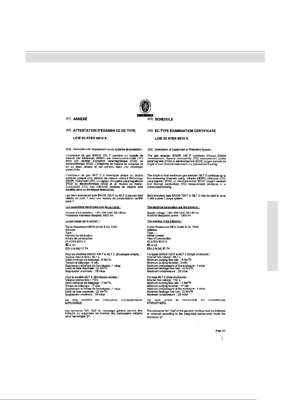
A-7Emerson Process Management GmbH & Co. OHG
A Appendix
MLT 2 / BINOS 100 F
ATEX Instruction Manual
ETC01035
02/2008
A.2.1 EC Type Examination Certicate
Page 67

A-8 Emerson Process Management GmbH & Co. OHG
MLT 2 / BINOS 100 F
ATEX Instruction Manual
ETC01035
02/2008
A.2.1 EC Type Examination Certicate
Page 68

A-9Emerson Process Management GmbH & Co. OHG
A Appendix
MLT 2 / BINOS 100 F
ATEX Instruction Manual
ETC01035
02/2008
A.2.1 EC Type Examination Certicate
Page 69

A-10 Emerson Process Management GmbH & Co. OHG
MLT 2 / BINOS 100 F
ATEX Instruction Manual
ETC01035
02/2008
A.2.1 EC Type Examination Certicate
Page 70

A-11Emerson Process Management GmbH & Co. OHG
A Appendix
MLT 2 / BINOS 100 F
ATEX Instruction Manual
ETC01035
02/2008
A.2.1 EC Type Examination Certicate
Page 71

A-12 Emerson Process Management GmbH & Co. OHG
MLT 2 / BINOS 100 F
ATEX Instruction Manual
ETC01035
02/2008
A.2.1 EC Type Examination Certicate
Page 72

A-13Emerson Process Management GmbH & Co. OHG
A Appendix
MLT 2 / BINOS 100 F
ATEX Instruction Manual
ETC01035
02/2008
A.3 Manufacturer´s Declaration
A.3 Manufacturer´s Declaration
Page 73

A-14 Emerson Process Management GmbH & Co. OHG
MLT 2 / BINOS 100 F
ATEX Instruction Manual
ETC01035
02/2008
Montageplatte
mounting plate
gn/ye
gn/ye
Erdungsbolzen an Seitenwand
Grounding pins at side panel
bk
bl
gn/ye
bk
bl
bk
X100
F100.1
X10.1
X10.2
L
+
-
N
PE
DC 24V out
SL 10
T 6,3A/250V
T 6,3A/250V
F100.2
.1
.2
.3
bl
gn/ye
gn/ye
L'
N'
PE'
br
bl
104
105
106
X100.4
101
100
109
108
/4.13
6ET3
Netzfilter
EMI filter
/2.5
Leitungsnummer / cable number
2-adrige Leitung / cable with 2 lines
12
Symbolerklärung:
Description of used icons:
Leitungsfarbe / cable colour
bl
Steckverbindung / plug connection
/2.4 Verweis auf Seite 2, Spalte 4 / reference to sh 2, row 4
ÄV 3442: Blatt 4: Zone 2 entfernt
MBa
13.11.07CPDF
Weitergabe sowie Vervielfältigung dieser
Unterlage, Verwertung und Mitteilung ihres
Inhaltes sind nur mit unserer Zustimmung
gestattet. Alle Rechte vorbehalten.
Copying of this document, and giving it to
others and the use or communication of the
contents thereof, are only allowed with our
agreement. All rights are reserved.
E
Micro Index Änderung, revision Datum Name
Bearb.
Gepr.
20___
Datum Name
Beschreibung, description Zeichnung-Nr.: Drawing-No.: Index
Ident-Nr.:
Blatt
Sheet
von
of
Auftrags-Nr.:+=
D
C
B
A
E
D
C
B
A
1 2 3 4 5 6 7 8 9
10 11 12 13 14 15 16
1 2 3 4 5 6 7 8 9 10 11 12 13 14 15 16
4.300-5137/4
1
4
03
12.11.
Bangert
Schmidt
MLT 2 Ex px
1-teilig / Single
14.11.
PDF
08.09.04
MBa
B
ÄV 2621: S2: FIP 02 hinzu
PDF
19.05.04
MBa
A
ÄV 2544: S2: Auf ACU 02 aktualisiert
C
A.4 Circuit Diagrams, Cat. 2 Equipment
A.4 Circuit Diagrams, Cat. 2 Equipment
A.4.1 MLT 2, single
Page 74

A-15Emerson Process Management GmbH & Co. OHG
A Appendix
MLT 2 / BINOS 100 F
ATEX Instruction Manual
ETC01035
02/2008
EEx i-Trennbausteine / EEx i couplers
Typ & Anzahl variabel / various types and numbers
Option / option)
200
DSP 01
Kartenkäfig
card cage
203
202
201
.9
.1
.9
.1
.25
.1
.25
.1
.37 .37
.1.1
P3
P2
P6
P25
Signal
P1
P2
P3
P6
ICB 01
P4
P5
Stromlaufplan/
schematics
4.300-0840
DIO
SIO
Optional
Digital I/O
Optional
Analog &
Serial I/O
HIM 10
Stromlaufplan / schematics:
4.300-2360
Stromlaufplan /
schematics:
4.300-4440
AFP 10
LCD
Auf Frontdeckel
At front door
Legende auf Seite 3
legend on sheet 3
(magn. Keyboard)
Übergabeelement
Cable adaptor
1:1
Digital I/O
Übergabeelement
Cable adaptor
1:1
Analog Out
Übergabeelement
Cable adaptor
1:1
Serial I/O
siehe Blatt 3
see sheet 3
Stromlaufplan
/ schematics:
4.300-1440
Stromlaufplan
/ schematics:
4.300-1040
.1
.37
.1
.25
.1
.9
Steckverbindungen an/zu ICB 01 sind Leiterplatten-Direktstecker,
alle anderen Verbindungen sind Leitungen.
Nummern an Kabelverbindungen sind Adernummern.
Connections to ICB 01 are pcb connectors, all other are wired.
Numbers at connections are wirenumbers.
/1.15
br
bl
24V
P6
P5
103
P1
Signal
Signal
Ext. Netzwerk (ECHELON)
External Network
LEM
(Option)
NET 01 (Option)
Stromlaufplan / schematics:
4.300-1800
Stromlaufplan
/ schematics:
4.300-2540
/3.13
P4P2
X40.1
X40.2
P2
P3
Signal
Signal
ACU 02
Stromlaufplan / schematics:
4.300-1900
FIP 02
Stromlaufplan / schematics:
4.300-4360
Optional
Ext. Netzwerk
External Network
(FIELDBUS)
P1-P4
P5
Signal
P14
J1
P19
P24
P22
P5
P3
P5 D3
MLT 2 Ex px
1-teilig / Single
Weitergabe sowie Vervielfältigung dieser
Unterlage, Verwertung und Mitteilung ihres
Inhaltes sind nur mit unserer Zustimmung
gestattet. Alle Rechte vorbehalten.
Copying of this document, and giving it to
others and the use or communication of the
contents thereof, are only allowed with our
agreement. All rights are reserved.
E
Micro Index Änderung, revision Datum Name
Bearb.
Gepr.
20___
Datum Name
Beschreibung, description Zeichnung-Nr.: Drawing-No.: Index
Ident-Nr.:
Blatt
Sheet
von
of
Auftrags-Nr.:+=
D
C
B
A
E
D
C
B
A
1 2 3 4 5 6 7 8 9
10 11 12 13 14 15 16
1 2 3 4 5 6 7 8 9 10 11 12 13 14 15 16
4.300-5137/4
2
4
03
12.11.
Bangert
Schmidt
14.11.
PDF
08.09.04
MBa
B
ÄV 2621: S2: FIP 02 hinzu
PDF
19.05.04
MBa
A
ÄV 2544: S2: Auf ACU 02 aktualisiert
B
A.4 Circuit Diagrams, Cat. 2 Equipment
Page 75

A-16 Emerson Process Management GmbH & Co. OHG
MLT 2 / BINOS 100 F
ATEX Instruction Manual
ETC01035
02/2008
Druck
Ch1
P31P30
Pressure
Ch2
Temperatur
Ch1
P18P17P16P11
Temperature
Ch4Ch3Ch2
DurchfluB
Ch1
P6P7P4P5
Flow
Ch4Ch3Ch2
AC-Detektoren
Ch1
P24P25P23P21
AC-detectors
Ch4Ch3Ch2 Ch5
Strahler
Ch1
P15P14P13P12
Source
Ch4Ch3Ch2
DC-Detektoren
Ch1
P20P19P28P26
ChopperDC-detectors
M2M1Ch4Ch3Ch2
Stromlaufplan / schematics:
4.300-2760
DSP 01
P27
physikalische Baugruppen (messprinzipabhängig)
thermostatisiert (Option)
physical components (depending on measurement system)
Thermostatted (option)
see sheet 2
s. Blatt 2
Leitungsnummer / cable number
2-adrige Leitung / cable with 2 lines
12
Symbolerklärung:
Description of used icons:
Leitungsfarbe / cable colour
bl
Steckverbindung / plug connection
/2.4 Verweis auf Seite 2, Spalte 4 / reference to sh 2, row 4
MLT 2 Ex px
1-teilig / Single
Weitergabe sowie Vervielfältigung dieser
Unterlage, Verwertung und Mitteilung ihres
Inhaltes sind nur mit unserer Zustimmung
gestattet. Alle Rechte vorbehalten.
Copying of this document, and giving it to
others and the use or communication of the
contents thereof, are only allowed with our
agreement. All rights are reserved.
E
Micro Index Änderung, revision Datum Name
Bearb.
Gepr.
20___
Datum Name
Beschreibung, description Zeichnung-Nr.: Drawing-No.: Index
Ident-Nr.:
Blatt
Sheet
von
of
Auftrags-Nr.:+=
D
C
B
A
E
D
C
B
A
1 2 3 4 5 6 7 8 9
10 11 12 13 14 15 16
1 2 3 4 5 6 7 8 9 10 11 12 13 14 15 16
4.300-5137/4
3
4
03
12.11.
Bangert
Schmidt
14.11.
A.4 Circuit Diagrams, Cat. 2 Equipment
Page 76

A-17Emerson Process Management GmbH & Co. OHG
A Appendix
MLT 2 / BINOS 100 F
ATEX Instruction Manual
ETC01035
02/2008
Anschluss / connection
des Steuergerätes FS850S für EX-Zone 1 /
of Control unit FS850S for EX Zone 1
Steuergerät
Control Unit
FS 850S
E Ex em[ib] IIC T6
L
N
PE
18
16
11
13
PE
15
14
17
12
Kontakte zur Spannungsfreischaltung
Contacts for isolating from supply
20
19
26
Proportionalventil
Proportional valve
25
SI 850
Ventilsicherung, spannungs- und ventilabhängig
Valve fuse, dependend on voltage and valve
PE
L'
N'
PE'
22
21
Zusatzventil f. ständige Durchspülung
Additional valve at continous purge
24
23
Standardventil
standard valve
Verwendeter Ventilanschluss abh. von Betriebsart
Valve terminals used depends on purge mode
/1.2
Steuerkreise Klemmen 1-10 eigensicher
Control circuits terminals 1-10 intrinsically safe
5
4
10
4
Schlüsselschalter auf Gehäusetür
Key Switch at front door
Analysator
Analyzer
Legende auf Seite 3
legend on sheet 3
AC in
(115 / 230 V)
p
>= 50 Pa
Separater Differenzdruckschalter (Option)
(Wenn mehrere Druckschalter verwendet werden,
erfolgt Reihenschaltung)
Separate differential pressure switch (option)
(In case more than 1 switch is used they are connected in serial)
MLT 2 Ex px
1-teilig / Single
Weitergabe sowie Vervielfältigung dieser
Unterlage, Verwertung und Mitteilung ihres
Inhaltes sind nur mit unserer Zustimmung
gestattet. Alle Rechte vorbehalten.
Copying of this document, and giving it to
others and the use or communication of the
contents thereof, are only allowed with our
agreement. All rights are reserved.
E
Micro Index Änderung, revision Datum Name
Bearb.
Gepr.
20___
Datum Name
Beschreibung, description Zeichnung-Nr.: Drawing-No.: Index
Ident-Nr.:
Blatt
Sheet
von
of
Auftrags-Nr.:+=
D
C
B
A
E
D
C
B
A
1 2 3 4 5 6 7 8 9
10 11 12 13 14 15 16
1 2 3 4 5 6 7 8 9 10 11 12 13 14 15 16
4.300-5137/4
4
4
03
12.11.
Bangert
Schmidt
14.11.
A.4 Circuit Diagrams, Cat. 2 Equipment
Page 77

A-18 Emerson Process Management GmbH & Co. OHG
MLT 2 / BINOS 100 F
ATEX Instruction Manual
ETC01035
02/2008
heated (option)
thermostatisiert (Option)
mounting plate
Montageplatte
gn/ye
gn/ye
Grounding pins at side panel
Erdungsbolzen an Seitenwand
Temperature controller (TEM 10)
Temperaturregler (TEM 10)
heater cabinet (Option)
Beheizer (Option)
bk
bl
gn/ye
bk
gn/ye
bl
107
bk
bl
gn/ye
bk
bl
bk
X100
F100.1
X10.1
X10.2
T 6,3A/250V
T 6,3A/250V
F100.2
.1
.2
.3
bl
gn/ye
gn/ye
L'
N'
PE'
br
bl
br
bl
104
/2.5
103
105
106
X100.4
X20
.5 .6 .7
TMF 01
Oberes Gehäuseteil
Upper compartement
Unteres Gehäuseteil
Lower compartement
F1: T 3.15 A / 250 V
101
100
102
X1
.11
.13
.16
.15
X1
.12
.14
.3 .4
rd
bl
F
.8
X20
T
X20
.2
.1
mounting plate
Montageplatte
physics plate
mounting plate
O2 cell
radiator
cover
111
110
115
114
112
drawer
113
109
108
/4.13
Legende auf Seite 3
legend on sheet 3
6ET3
Netzfilter
EMI filter
L
+
-
N
PE
DC 24V out
SL 10
~
AC in (120/230V)
Weitergabe sowie Vervielfältigung dieser
Unterlage, Verwertung und Mitteilung ihres
Inhaltes sind nur mit unserer Zustimmung
gestattet. Alle Rechte vorbehalten.
Copying of this document, and giving it to
others and the use or communication of the
contents thereof, are only allowed with our
agreement. All rights are reserved.
E
Micro Index Änderung, revision Datum Name
Bearb.
Gepr.
20___
Datum Name
Beschreibung, description Zeichnung-Nr.: Drawing-No.: Index
Ident-Nr.:
Blatt
Sheet
von
of
Auftrags-Nr.:+=
D
C
B
A
E
D
C
B
A
1 2 3 4 5 6 7 8 9
10 11 12 13 14 15 16
1 2 3 4 5 6 7 8 9 10 11 12 13 14 15 16
4.300-5132/4
1
4
03
04.11.
Bangert
Schmidt
04.11.
MLT 2 Ex px
2-teilig / DUAL
ÄV 2611: S. Blatt 2 / s. Sheet 2
MBa
03.09.04A
B
PDF
ÄV 3442: Blatt 4: Zone 2 entfernt
MBa
13.11.07BPDF
A.4 Circuit Diagrams, Cat. 2 Equipment
A.4.2 MLT 2, dual
Page 78

A-19Emerson Process Management GmbH & Co. OHG
A Appendix
MLT 2 / BINOS 100 F
ATEX Instruction Manual
ETC01035
02/2008
EEx i-Trennbausteine / EEx i couplers
Typ & Anzahl variabel / various types and numbers
Option / option)
200
DSP 01
Kartenkäfig
card cage
203
202
201
.9
.1
.9
.1
.25
.1
.25
.1
.37 .37
.1.1
P3
P2
P6
P25
Signal
P1
P2
P3
P6
ICB 01
P4
P5
Stromlaufplan/
schematics
4.300-0840
Oberes Gehäuseteil
Upper compartement
DIO
SIO
Optional
Digital I/O
Optional
Analog &
Serial I/O
HIM 10
Stromlaufplan / schematics:
4.300-2360
Stromlaufplan /
schematics:
4.300-4440
AFP 10
LCD
Auf Frontdeckel
At front door
Legende auf Seite 3
legend on sheet 3
(magn. Keyboard)
Übergabeelement
Cable adaptor
1:1
Digital I/O
Übergabeelement
Cable adaptor
1:1
Analog Out
Übergabeelement
Cable adaptor
1:1
Serial I/O
siehe Blatt 3
see sheet 3
Stromlaufplan
/ schematics:
4.300-1440
Stromlaufplan
/ schematics:
4.300-1040
.1
.37
.1
.25
.1
.9
Steckverbindungen an/zu ICB 01 sind Leiterplatten-Direktstecker,
alle anderen Verbindungen sind Leitungen.
Nummern an Kabelverbindungen sind Adernummern.
Connections to ICB 01 are pcb connectors, all other are wired.
Numbers at connections are wirenumbers.
/1.15
br
bl
24V
P6
P5
103
P1
Signal
Signal
Ext. Netzwerk (ECHELON)
External Network
LEM
(Option)
NET 01 (Option)
Stromlaufplan / schematics:
4.300-1800
Stromlaufplan
/ schematics:
4.300-2540
/3.13
P4P2
X40.1
X40.2
P2
P3
Signal
Signal
ACU 02
Stromlaufplan / schematics:
4.300-1900
FIP 02
Stromlaufplan / schematics:
4.300-4360
Optional
Ext. Netzwerk
External Network
(FIELDBUS)
P1-P4
P5
Signal
P14
J1
P19
P24
P22
P5
P3
P5 D3
MLT 2 Ex px
2-teilig / DUAL
Weitergabe sowie Vervielfältigung dieser
Unterlage, Verwertung und Mitteilung ihres
Inhaltes sind nur mit unserer Zustimmung
gestattet. Alle Rechte vorbehalten.
Copying of this document, and giving it to
others and the use or communication of the
contents thereof, are only allowed with our
agreement. All rights are reserved.
E
Micro Index Änderung, revision Datum Name
Bearb.
Gepr.
20___
Datum Name
Beschreibung, description Zeichnung-Nr.: Drawing-No.: Index
Ident-Nr.:
Blatt
Sheet
von
of
Auftrags-Nr.:+=
D
C
B
A
E
D
C
B
A
1 2 3 4 5 6 7 8 9
10 11 12 13 14 15 16
1 2 3 4 5 6 7 8 9 10 11 12 13 14 15 16
4.300-5132/4
2
4
Bangert
Schmidt
03
04.11.
04.11.
ÄV 2611: NET, ACU 02 hinzu / added NET, ACU 02
MBa03.09.04A
A
PDF
A.4 Circuit Diagrams, Cat. 2 Equipment
Page 79

A-20 Emerson Process Management GmbH & Co. OHG
MLT 2 / BINOS 100 F
ATEX Instruction Manual
ETC01035
02/2008
Upper compartement
Lower compartement
Druck
Ch1
P31P30
Pressure
Ch2
Temperatur
Ch1
P18P17P16P11
Temperature
Ch4Ch3Ch2
DurchfluB
Ch1
P6P7P4P5
Flow
Ch4Ch3Ch2
AC-Detektoren
Ch1
P24P25P23P21
AC-detectors
Ch4Ch3Ch2 Ch5
Strahler
Ch1
P15P14P13P12
Source
Ch4Ch3Ch2
DC-Detektoren
Ch1
P20P19P28P26
ChopperDC-detectors
M2M1Ch4Ch3Ch2
Stromlaufplan / schematics:
4.300-2760
DSP 01
P27
physikalische Baugruppen (messprinzipabhängig)
thermostatisiert (Option)
physical components (depending on measurement system)
Thermostatted (option)
see sheet 2
s. Blatt 2
Leitungsnummer / cable number
2-adrige Leitung / cable with 2 lines
12
Symbolerklärung:
Description of used icons:
Leitungsfarbe / cable colour
bl
Steckverbindung / plug connection
/2.4 Verweis auf Seite 2, Spalte 4 / reference to sh 2, row 4
MLT 2 Ex px
2-teilig / DUAL
Weitergabe sowie Vervielfältigung dieser
Unterlage, Verwertung und Mitteilung ihres
Inhaltes sind nur mit unserer Zustimmung
gestattet. Alle Rechte vorbehalten.
Copying of this document, and giving it to
others and the use or communication of the
contents thereof, are only allowed with our
agreement. All rights are reserved.
E
Micro Index Änderung, revision Datum Name
Bearb.
Gepr.
20___
Datum Name
Beschreibung, description Zeichnung-Nr.: Drawing-No.: Index
Ident-Nr.:
Blatt
Sheet
von
of
Auftrags-Nr.:+=
D
C
B
A
E
D
C
B
A
1 2 3 4 5 6 7 8 9
10 11 12 13 14 15 16
1 2 3 4 5 6 7 8 9 10 11 12 13 14 15 16
4.300-5132/4
3
4
Bangert
Schmidt
03
04.11.
04.11.
A
A.4 Circuit Diagrams, Cat. 2 Equipment
Page 80

A-21Emerson Process Management GmbH & Co. OHG
A Appendix
MLT 2 / BINOS 100 F
ATEX Instruction Manual
ETC01035
02/2008
Anschluss / connection
des Steuergerätes FS850S für EX-Zone 1 /
of Control unit FS850S for EX Zone 1
L
N
PE
18
16
11
13
PE
15
14
17
12
20
19
26
Proportionalventil
Proportional valve
25
SI 850
Ventilsicherung, spannungs- und ventilabhängig
Valve fuse, dependend on voltage and valve
PE
L'
N'
PE'
22
21
Zusatzventil für ständige Durchspülung
Additional valve at continous purge
24
23
Standardventil
standard valve
/1.2
5
4
10
4
Schlüsselschalter auf Gehäusetür
Key Switch at front door
p
Legende auf Seite 3
legend on sheet 3
AC in
(115 / 230 V)
Steuergerät
Control Unit
FS 850S
E Ex em[ib] IIC T6
Kontakte zur Spannungsfreischaltung
Contacts for isolating from supply
Verwendeter Ventilanschluss abh. von Betriebsart
Valve terminals used depends on purge mode
Steuerkreise Klemmen 1-10 eigensicher
Control circuits terminals 1-10 intrinsically safe
>= 50 Pa
Separater Differenzdruckschalter (Option)
(Wenn mehrere Druckschalter verwendet werden,
erfolgt Reihenschaltung)
Separate differential pressure switch (option)
(In case more than 1 switch is used they are connected in serial)
Analysator
Analyzer
ÄV 2611: S. Blatt 2 / s. Sheet 2
MBa
03.09.04APDF
ÄV 3442: Blatt 4: Zone 2 entfernt
MBa
13.11.07BPDF
MLT 2 Ex px
2-teilig / DUAL
Weitergabe sowie Vervielfältigung dieser
Unterlage, Verwertung und Mitteilung ihres
Inhaltes sind nur mit unserer Zustimmung
gestattet. Alle Rechte vorbehalten.
Copying of this document, and giving it to
others and the use or communication of the
contents thereof, are only allowed with our
agreement. All rights are reserved.
E
Micro Index Änderung, revision Datum Name
Bearb.
Gepr.
20___
Datum Name
Beschreibung, description Zeichnung-Nr.: Drawing-No.: Index
Ident-Nr.:
Blatt
Sheet
von
of
Auftrags-Nr.:+=
D
C
B
A
E
D
C
B
A
1 2 3 4 5 6 7 8 9
10 11 12 13 14 15 16
1 2 3 4 5 6 7 8 9 10 11 12 13 14 15 16
4.300-5132/4
4
4
Bangert
Schmidt
03
04.11.
04.11.
A
A.4 Circuit Diagrams, Cat. 2 Equipment
Page 81

A-22 Emerson Process Management GmbH & Co. OHG
MLT 2 / BINOS 100 F
ATEX Instruction Manual
ETC01035
02/2008
/2.13
8pol
(option)
Ventile
valves
ws
br
X7
Temp. Sensor 1
(Chopper)
14pol
X1
J9
(9pol)
(9pol)
8pol
X1 (Output)
INTERFACE
X2 (Analog I/O)
X3 (Grenzwerte /
Threshold)
P7
Ch1
DC-Detektoren /
DC-
detectors
P8
Ch2
X3
Ch1
X4
Ch2
X2
M1
Strahler /
beamer
Chopper
Druck /
pressure
physikalische Baugruppen (messprinzipabhängig)
physical components (dep. on measurement system)
X10.2
X10.1
P1.1 .2
X1.1
X1.2
X1.3
L'
N'
PE'
Load
Line
P2
Heizung PO -Zelle /
2
Peater PO cell
2
HIX 04
4.300-2660
X2
X3
X1
BKS 20
4
5
63
2
1
F100.2 T3.15A / 250V
F100.1 T3.15A / 250V
ws
br
Pumpe
pump
(option)
(9pol)
(9pol)
BSI 10
4.300-4320
HIM 01
magn. Keyboard
7pol
4.300-4280
6 ETC1
Netzfilter
EMI filter
X9.1
Erdungsbolzen an der Seitenwand
Grounding pins at side panel
L
+
-
N
PE
DC 24V out
SL 5 (SL 10)
~
AC in (120/230V)
LED-Display
Signal
Signal
(Option)
4.300-1580
Serial I/O &
Status signals
Übergabeelement
Cable adaptor
1:1
Analog I/O
Übergabeelement
Cable adaptor
1:1
Interface
Übergabeelement
Cable adaptor
1:1
Digital Out
Übergabeelement
Cable adaptor
1:1
Output
P3 P6
Temp. Sensor 2
X5
Ch1
AC/DC-Detektoren /
AC/DC-
detectors
X6
Ch2
X1
(9pol)
Übergabeelement
Cable adaptor
1:1
Interface
Übergabeelement
Cable adaptor
1:1
Output
P19
P21
Alternativ
Alternatively
(9pol)
FIP 02
Stromlaufplan / schematics:
4.300-4360
Ext. Netzwerk
External Network
(FIELDBUS)
P1-P4
P6
FIF 01
Stromlaufplan / schematics:
4.300-2600
Ext. Netzwerk
External Network
(FIELDBUS)
P12, P14
P15, P17
7 x Digital Input
P3-P8
P13
X21
X1
P1 T1 T2
Leitungsnummer / cable number
2-adrige Leitung / cable with 2 lines
12
Symbolerklärung:
Description of used icons:
Leitungsfarbe / cable colour
bl
Steckverbindung / plug connection
/2.4 Verweis auf Seite 2, Spalte 4 / reference to sh 2, row 4
A
ÄV 3444: Blatt 4: Zone 2 entfernt
MBa
14.11.07APDF
Weitergabe sowie Vervielfältigung dieser
Unterlage, Verwertung und Mitteilung ihres
Inhaltes sind nur mit unserer Zustimmung
gestattet. Alle Rechte vorbehalten.
Copying of this document, and giving it to
others and the use or communication of the
contents thereof, are only allowed with our
agreement. All rights are reserved.
E
Micro Index Änderung, revision Datum Name
Bearb.
Gepr.
20___
Datum Name
Beschreibung, description Zeichnung-Nr.: Drawing-No.: Index
Ident-Nr.:
Blatt
Sheet
von
of
Auftrags-Nr.:+=
D
C
B
A
E
D
C
B
A
1 2 3 4 5 6 7 8 9
10 11 12 13 14 15 16
1 2 3 4 5 6 7 8 9 10 11 12 13 14 15 16
4.300-5144/4
1
2
04
08.09.
Bangert
Bangert
BINOS 100F Ex px
08.09.
A.4 Circuit Diagrams, Cat. 2 Equipment
A.4.3 BINOS® 100 F
Page 82

A-23Emerson Process Management GmbH & Co. OHG
A Appendix
MLT 2 / BINOS 100 F
ATEX Instruction Manual
ETC01035
02/2008
Anschluss / connection
des Steuergerätes FS850S für EX-Zone 1 /
of Control unit FS850S for EX Zone 1
Steuergerät
Control Unit
FS 850S
E Ex em[ib] IIC T6
L
N
PE
18
16
11
13
PE
15
14
17
12
Kontakte zur Spannungsfreischaltung
Contacts for isolating from supply
20
19
26
Proportionalventil
Proportional valve
25
SI 850
Ventilsicherung, spannungs- und ventilabhängig
Valve fuse, dependend on voltage and valve
PE
L'
N'
PE'
22
21
Zusatzventil für ständige Durchspülung
Additional valve at continous purge
24
23
Standardventil
standard valve
Verwendeter Ventilanschluss abh. von Betriebsart
Valve terminals used depends on purge mode
/1.2
Steuerkreise Klemmen 1-10 eigensicher
Control circuits terminals 1-10 intrinsically safe
5
4
10
4
Schlüsselschalter auf Gehäusetür
Key Switch at front door
Analysator
Analyzer
p
>= 50 Pa
Legende auf Seite 1
legend on sheet 1
AC in
(115 / 230 V)
Separater Differenzdruckschalter (Option)
(Wenn mehrere Druckschalter verwendet werden,
erfolgt Reihenschaltung)
Separate differential pressure switch (option)
(In case more than 1 switch is used they are connected in serial)
BINOS 100F Ex px
Weitergabe sowie Vervielfältigung dieser
Unterlage, Verwertung und Mitteilung ihres
Inhaltes sind nur mit unserer Zustimmung
gestattet. Alle Rechte vorbehalten.
Copying of this document, and giving it to
others and the use or communication of the
contents thereof, are only allowed with our
agreement. All rights are reserved.
E
Micro Index Änderung, revision Datum Name
Bearb.
Gepr.
20___
Datum Name
Beschreibung, description Zeichnung-Nr.: Drawing-No.: Index
Ident-Nr.:
Blatt
Sheet
von
of
Auftrags-Nr.:+=
D
C
B
A
E
D
C
B
A
1 2 3 4 5 6 7 8 9
10 11 12 13 14 15 16
1 2 3 4 5 6 7 8 9 10 11 12 13 14 15 16
2
2
4.300-5144/4
04
08.09.
Bangert
Bangert
08.09.
A.4 Circuit Diagrams, Cat. 2 Equipment
Page 83

A-24 Emerson Process Management GmbH & Co. OHG
MLT 2 / BINOS 100 F
ATEX Instruction Manual
ETC01035
02/2008
Montageplatte
mounting plate
g
n
/
y
e
gn/ye
Erdungsbolzen an Seitenwand
Grounding pins at side panel
bk
bl
gn/ye
bk
bl
bk
X100
F100.1
X10.1
X10.2
L
+
-
N
PE
DC 24V out
SL 10
T 6,3A/250V
T 6,3A/250V
F100.2
.1
.2
.3
bl
gn/ye
gn/ye
L'
N'
PE'
br
bl
104
105
106
X100.4
101
100
109
108
/4.13
6ET3
Netzfilter
EMI filter
/2.5
Leitungsnummer / cable number
2-adrige Leitung / cable with 2 lines
12
Symbolerklärung:
Description of used icons:
Leitungsfarbe / cable colour
bl
Steckverbindung / plug connection
/2.4 Verweisauf Seite 2, Spalte 4 / reference to sh 2, row 4
Bearb.
Gepr.
20___
Datum Name
Beschreibung, description
Zeichnung-Nr.: Drawing-No.: Index
Ident-Nr.:
Blatt
Sheet
von
of
Auftrags-Nr.:+=
E
D
C
B
A
1 2 3 4 5 6 7 8 9 10 11 12 13 14 15 16
4.300-5138/4
1
4
03
12.11.
Bangert
Schmidt
MLT 2 EEx Zone 2
1-teilig / Single
12.11.
31.03.05
MBa
A
ÄV 2615: S2: ACU 02 und FIP 02 hinzu
A
A.5 Circuit Diagrams, Cat. 3 Equipment
A.5 Circuit Diagrams, Cat. 3 Equipment
A.5.1 MLT 2, single
Page 84

A-25Emerson Process Management GmbH & Co. OHG
A Appendix
MLT 2 / BINOS 100 F
ATEX Instruction Manual
ETC01035
02/2008
EEx i-Trennbausteine / EEx i couplers
Typ & Anzahl variabel / various types and numbers
Option / option)
200
DSP 01
Kartenkäfig
card cage
203
202
201
.9
.1
.9
.1
.25
.1
.25
.1
.37 .37
.1.1
P3
P2
P6
P25
Signal
P1
P2
P3
P6
ICB 01
P4
P5
Stromlaufplan/
schematics
4.300-0840
DIO
SIO
Optional
Digital I/O
Optional
Analog &
Serial I/O
HIM 10
Stromlaufplan / schematics:
4.300-2360
Stromlaufplan /
schematics:
4.300-4440
AFP 10
LCD
Auf Frontdeckel
At front door
Legende auf Seite 3
legend on sheet 3
(magn. Keyboard)
Übergabeelement
1:1
Digital I/O
Cable adaptor
Übergabeelement
1:1
Analog Out
Cable adaptor
Übergabeelement
1:1
Serial I/O
Cable adaptor
siehe Blatt 3
see sheet 3
Stromlaufplan
/ schematics:
4.300-1440
Stromlaufplan
/ schematics:
4.300-1040
.1
.37
.1
.25
.1
.9
Steckverbindungen an/zu ICB 01 sind Leiterplatten-Direktstecker,
alle anderen Verbindungen sind Leitungen.
Nummern an Kabelverbindungen sind Adernummern.
Connections to ICB 01 are pcb connectors, all other are wired.
Numbers at connections are wirenumbers.
/1.15
br
bl
24V
P6
P5
103
P1
Signal
Signal
Ext. Netzwerk (ECHELON)
External Network
LEM
(Option)
NET 01 (Option)
Stromlaufplan / schematics:
4.300-1800
Stromlaufplan
/ schematics:
4.300-2540
/3.13
P4
P2
X
4
0
.
1
X
4
0
.
2
P2
P3
Signal
Signal
ACU 02
Stromlaufplan / schematics:
4.300-1900
FIP 02
Stromlaufplan / schematics:
4.300-4360
Optional
Ext. Netzwerk
(FIELDBUS)
External Network
P1-P4
P5
Signal
P14
J1
P19
P24
P22
P5
P3
P5 D3
Bearb.
Gepr.
20___
Datum Name
Beschreibung, description
Zeichnung-Nr.: Drawing-No.: Index
Ident-Nr.:
Blatt
Sheet
von
of
Auftrags-Nr.:+=
E
D
C
B
A
1 2 3 4 5 6 7 8 9 10 11 12 13 14 15 16
4.300-5138/4
2
4
03
12.11.
Bangert
Schmidt
MLT 2 EEx Zone 2
1-teilig / Single
12.11.
31.03.05
MBa
A
ÄV 2615: S2: ACU 02 und FIP 02 hinzu
A
A.5 Circuit Diagrams, Cat. 3 Equipment
Page 85

A-26 Emerson Process Management GmbH & Co. OHG
MLT 2 / BINOS 100 F
ATEX Instruction Manual
ETC01035
02/2008
Druck
Ch1
P31P30
Pressure
Ch2
Temperatur
Ch1
P18P17P16P11
Temperature
Ch4Ch3Ch2
DurchfluB
Ch1
P6P7P4P5
Flow
Ch4Ch3Ch2
AC-Detektoren
Ch1
P24P25P23P21
AC-detectors
Ch4Ch3Ch2 Ch5
Strahler
Ch1
P15P14P13P12
Source
Ch4Ch3Ch2
DC-Detektoren
Ch1
P20P19P28P26
ChopperDC-detectors
M2M1Ch4Ch3Ch2
Stromlaufplan / schematics:
4.300-2760
DSP 01
P27
physikalische Baugruppen (messprinzipabhängig)
thermostatisiert (Option)
physical components (depending on measurement system)
Thermostatted (option)
see sheet 2
s. Blatt 2
Leitungsnummer / cable number
2-adrige Leitung / cable with 2 lines
12
Symbolerklärung:
Description of used icons:
Leitungsfarbe / cable colour
bl
Steckverbindung / plug connection
/2.4 Verweis auf Seite 2, Spalte 4 / reference to sh 2, row 4
Bearb.
Gepr.
20___
Datum Name
Beschreibung, description
Zeichnung-Nr.: Drawing-No.: Index
Ident-Nr.:
Blatt
Sheet
von
of
Auftrags-Nr.:+=
E
D
C
B
A
4.300-5138/4
3
4
03
12.11.
Bangert
Schmidt
MLT 2 EEx Zone 2
1-teilig / Single
12.11.
A.5 Circuit Diagrams, Cat. 3 Equipment
Page 86

A-27Emerson Process Management GmbH & Co. OHG
A Appendix
MLT 2 / BINOS 100 F
ATEX Instruction Manual
ETC01035
02/2008
PE
Analysator /
Analyzer
Abhängig von den Kundenanforderungen /
dependent on the customer requirements
Kontakt 1
/contact 1
Kontakt 2
/contact 2
3
2
Spülmittelventil
/ purge valve
SEPARATERDIFFERENZDRUCKSCHALTER (OPTION)
(WENN MEHRERE DURCKSCHALTER VERWENDET WERDEN,
ERFOLGT REIHENSCHALTUNG)
Separate differential pressure switch (option)
(In case more than 1 switsch is used they are connected in serial)
5
6
4
>= 50 Pa
p
1
/1.2
AC in
(
PE'
N'
L'
E Ex nAC[P] IIC T6
PE
9
7
8
10
PE
PE
N
L
Steuergerät
Control Unit
FS840
N
L
.2
.1
X30
Leitungsnummer / cable number
2-adrige Leitung / cable with 2 lines
12
Symbolerklärung:
Description of used icons:
Leitungsfarbe / cable colour
bl
Steckverbindung / plug connection
/2.4 Verweisauf Seite 2, Spalte 4 / reference to sh 2, row 4
Bearb.
Gepr.
20___
Datum Name
Beschreibung, description Zeichnung-Nr.: Drawing-No.: Index
Ident-Nr.:
Blatt
Sheet
von
of
Auftrags-Nr.:+=
E
D
C
B
A
1 2 3 4 5 6 7 8 9 10 11 12 13 14 15 16
4.300-5138/4
4
4
03
12.11.
Bangert
Schmidt
MLT 2 EEx Zone 2
1-teilig / Single
12.11.
A.5 Circuit Diagrams, Cat. 3 Equipment
Page 87

A-28 Emerson Process Management GmbH & Co. OHG
MLT 2 / BINOS 100 F
ATEX Instruction Manual
ETC01035
02/2008
heated (option)
thermostatisiert (Option)
mounting plate
Montageplatte
g
n
/
y
e
gn/ye
Grounding pins at side panel
Erdungsbolzen an Seitenwand
Temperaturecontroller (TEM 10)
Temperaturregler (TEM 10)
heater cabinet (Option)
Beheizer (Option)
bk
bl
gn/ye
bk
gn/ye
bl
107
bk
bl
gn/ye
bk
bl
bk
X100
F100.1
X10.1
X10.2
L
+
-
N
PE
DC 24V out
SL 10
T 6,3A/250V
T 6,3A/250V
F100.2
.1
.2
.3
bl
gn/ye
gn/ye
L'
N'
PE'
br
bl
br
bl
104
/2.5
103
105
106
X100.4
X20
.5 .6 .7
TMF 01
Oberes Gehäuseteil
Upper compartement
Unteres Gehäuseteil
Lower compartement
F1: T 3.15 A / 250 V
101
100
102
X1
.11
.13
.16
.15
X1
.12
.14
.3 .4
rd
bl
F
.8
X20
T
X20
.2
.1
mounting plate
Montageplatte
physics plate
mounting plate
O2 cell
radiator
cover
111
110
115
114
112
drawer
113
109
108
/4.13
Legende auf Seite 3
legend on sheet 3
6ET3
Netzfilter
EMI filter
Bearb.
Gepr.
20___
Datum Name
Beschreibung, description
Zeichnung-Nr.: Drawing-No.: Index
Ident-Nr.:
Blatt
Sheet
von
of
Auftrags-Nr.:+=
E
D
C
B
A
1 2 3 4 5 6 7 8 9 10 11 12 13 14 15 16
4.300-5134/4
1
4
03
06.11.
Bangert
Schmidt
11.11.
Zone 2 variation for measuring flammable gases
MLT 2 EEx Zone 2
2-teilig / DUAL
A
ÄV 2401; Seite 2 - LON-Anschluß hinzu 13.11.03 MBa
B
B
ÄV 2617; S2 - ACU 02 und FIP 02 hinzu 31.03.05 MBa
A.5 Circuit Diagrams, Cat. 3 Equipment
A.5.2 MLT 2, dual
Page 88

A-29Emerson Process Management GmbH & Co. OHG
A Appendix
MLT 2 / BINOS 100 F
ATEX Instruction Manual
ETC01035
02/2008
Oberes Gehäuseteil
Upper compartement
EEx i-Trennbausteine / EEx i couplers
Typ & Anzahl variabel / various types and numbers
Option / option)
200
DSP 01
Kartenkäfig
card cage
203
202
201
.9
.1
.9
.1
.25
.1
.25
.1
.37 .37
.1.1
P3
P2
P6
P25
Signal
P1
P2
P3
P6
ICB 01
P4
P5
Stromlaufplan/
schematics
4.300-0840
DIO
SIO
Optional
Digital I/O
Optional
Analog &
Serial I/O
HIM 10
Stromlaufplan / schematics:
4.300-2360
Stromlaufplan /
schematics:
4.300-4440
AFP 10
LCD
Auf Frontdeckel
At front door
Legende auf Seite 3
legend on sheet 3
(magn. Keyboard)
Übergabeelement
1:1
Digital I/O
Cable adaptor
Übergabeelement
1:1
Analog Out
Cable adaptor
Übergabeelement
1:1
Serial I/O
Cable adaptor
siehe Blatt 3
see sheet 3
Stromlaufplan
/ schematics:
4.300-1440
Stromlaufplan
/ schematics:
4.300-1040
.1
.37
.1
.25
.1
.9
Steckverbindungen an/zu ICB 01 sind Leiterplatten-Direktstecker,
alle anderen Verbindungen sind Leitungen.
Nummern an Kabelverbindungen sind Adernummern.
Connections to ICB 01 are pcb connectors, all other are wired.
Numbers at connections are wirenumbers.
/1.15
br
bl
24V
P6
P5
103
P1
Signal
Signal
Ext. Netzwerk (ECHELON)
External Network
LEM
(Option)
NET 01 (Option)
Stromlaufplan / schematics:
4.300-1800
Stromlaufplan
/ schematics:
4.300-2540
/3.13
P4
P2
X
4
0
.
1
X
4
0
.
2
P2
P3
Signal
Signal
ACU 02
Stromlaufplan / schematics:
4.300-1900
FIP 02
Stromlaufplan / schematics:
4.300-4360
Optional
Ext. Netzwerk
(FIELDBUS)
External Network
P1-P4
P5
Signal
P14
J1
P19
P24
P22
P5
P3
P5 D3
Bearb.
Gepr.
20___
Datum Name
Beschreibung, description
Zeichnung-Nr.: Drawing-No.: Index
Ident-Nr.:
Blatt
Sheet
von
of
Auftrags-Nr.:+=
E
D
C
B
A
1 2 3 4 5 6 7 8 9 10 11 12 13 14 15 16
4.300-5134/4
2
4
03
06.11.
Bangert
Schmidt
11.11.
MLT 2 EEx Zone 2
2-teilig / DUAL
A
ÄV 2401; Seite 2 - LON-Anschluß hinzu 13.11.03 MBa
B
PDF
B
ÄV 2617; S2 - ACU 02 und FIP 02 hinzu 31.03.05 MBa
PDF
A.5 Circuit Diagrams, Cat. 3 Equipment
Page 89

A-30 Emerson Process Management GmbH & Co. OHG
MLT 2 / BINOS 100 F
ATEX Instruction Manual
ETC01035
02/2008
Upper compartement
Lower compartement
Druck
Ch1
P31P30
Pressure
Ch2
Temperatur
Ch1
P18P17P16P11
Temperature
Ch4Ch3Ch2
DurchfluB
Ch1
P6P7P4P5
Flow
Ch4Ch3Ch2
AC-Detektoren
Ch1
P24P25P23P21
AC-detectors
Ch4Ch3Ch2 Ch5
Strahler
Ch1
P15P14P13P12
Source
Ch4Ch3Ch2
DC-Detektoren
Ch1
P20P19P28P26
ChopperDC-detectors
M2M1Ch4Ch3Ch2
Stromlaufplan / schematics:
4.300-2760
DSP 01
P27
physikalische Baugruppen (messprinzipabhängig)
thermostatisiert (Option)
physical components (depending on measurement system)
Thermostatted (option)
see sheet 2
s. Blatt 2
Leitungsnummer / cable number
2-adrige Leitung / cable with 2 lines
12
Symbolerklärung:
Description of used icons:
Leitungsfarbe / cable colour
bl
Steckverbindung / plug connection
/2.4 Verweisauf Seite 2, Spalte 4 / reference to sh 2, row 4
Bearb.
Gepr.
20___
Datum Name
Beschreibung, description
Zeichnung-Nr.: Drawing-No.: Index
Ident-Nr.:
Blatt
Sheet
von
of
Auftrags-Nr.:+=
E
D
C
B
A
1 2 3 4 5 6 7 8 9 10 11 12 13 14 15 16
4.300-5134/4
3
4
03
06.11.
Bangert
Schmidt
11.11.
MLT 2 EEx Zone 2
2-teilig / DUAL
A
ÄV 2401; Seite 2 - LON-Anschluß hinzu 13.11.03 MBa
A
A.5 Circuit Diagrams, Cat. 3 Equipment
Page 90

A-31Emerson Process Management GmbH & Co. OHG
A Appendix
MLT 2 / BINOS 100 F
ATEX Instruction Manual
ETC01035
02/2008
PE
Analysator /
Analyzer
Abhängig von den Kundenanforderungen /
dependent on the customer requirements
Kontakt 1
/contact 1
Kontakt 2
/contact 2
3
2
Spülmittelventil
/ purge valve
SEPARATERDIFFERENZDRUCKSCHALTER (OPTION)
(WENN MEHRERE DRUCKSCHALTER VERWENDET WERDEN,
ERFOLGT REIHENSCHALTUNG)
Separate differential pressure switch (option)
(In case more than 1 switsch is used they are connected in serial)
5
6
4
>= 50 Pa
p
1
/1.2
AC in
PE'
N'
L'
E Ex nAC[P] IIC T6
PE
9
7
8
10
PE
PE
N
L
Steuergerät
Control Unit
FS840
N
L
.2
.1
X30
Legende auf Seite 3
legend on sheet 3
Bearb.
Gepr.
20___
Datum Name
Beschreibung, description
Zeichnung-Nr.: Drawing-No.: Index
Ident-Nr.:
Blatt
Sheet
von
of
Auftrags-Nr.:+=
E
D
C
B
A
1 2 3 4 5 6 7 8 9 10 11 12 13 14 15 16
4.300-5134/4
4
4
03
06.11.
Bangert
Schmidt
11.11.
MLT 2 EEx Zone 2
2-teilig / DUAL
A
ÄV 2401; Seite 2 - LON-Anschluß hinzu 13.11.03 MBa
A
A.5 Circuit Diagrams, Cat. 3 Equipment
Page 91

A-32 Emerson Process Management GmbH & Co. OHG
MLT 2 / BINOS 100 F
ATEX Instruction Manual
ETC01035
02/2008
/2.13
8pol
(option)
Ventile
valves
ws
br
X7
Temp. Sensor 1
(Chopper)
14pol
X1
J9
(9pol)
(9pol)
8pol
X1 (Output)
INTERFACE
X2 (Analog I/O)
X3 (Grenzwerte /
Threshold)
P7
Ch1
DC-Detektoren /
DC-
detectors
P8
Ch2
X3
Ch1
X4
Ch2
X2
M1
Strahler /
beamer
Chopper
Druck /
pressure
physikalische Baugruppen (messprinzipabhängig)
physical components (dep. on measurement system)
X10.2
X10.1
P1.1 .2
X1.1
X1.2
X1.3
L'
N'
PE'
Load
Line
P2
Heizung PO -Zelle /
2
Peater PO cell
2
HIX 04
4.300-2660
X2
X3
X1
BKS 20
4
5
63
2
1
F100.2 T3.15A / 250V
F100.1 T3.15A / 250V
ws
br
Pumpe
pump
(option)
(9pol)
(9pol)
BSI 10
4.300-4320
HIM 01
magn. Keyboard
7pol
4.300-4280
6 ETC1
Netzfilter
EMI filter
X9.1
Erdungsbolzen an der Seitenwand
Grounding pins at side panel
L
+
-
N
PE
DC 24V out
SL 5 (SL 10)
~
AC in (120/230V)
LED-Display
Signal
Signal
(Option)
4.300-1580
Serial I/O &
Status signals
Übergabeelement
Cable adaptor
1:1
Analog I/O
Übergabeelement
Cable adaptor
1:1
Interface
Übergabeelement
Cable adaptor
1:1
Digital Out
Übergabeelement
Cable adaptor
1:1
Output
P3 P6
Temp. Sensor 2
X5
Ch1
AC/DC-Detektoren /
AC/DC-
detectors
X6
Ch2
X1
(9pol)
Übergabeelement
Cable adaptor
1:1
Interface
Übergabeelement
Cable adaptor
1:1
Output
P19
P21
Alternativ
Alternatively
(9pol)
FIP 02
Stromlaufplan / schematics:
4.300-4360
Ext. Netzwerk
External Network
(FIELDBUS)
P1-P4
P6
FIF 01
Stromlaufplan / schematics:
4.300-2600
Ext. Netzwerk
External Network
(FIELDBUS)
P12, P14
P15, P17
7 x Digital Input
P3-P8
P13
X21
X1
P1 T1 T2
Leitungsnummer / cable number
2-adrige Leitung / cable with 2 lines
12
Symbolerklärung:
Description of used icons:
Leitungsfarbe / cable colour
bl
Steckverbindung / plug connection
/2.4 Verweis auf Seite 2, Spalte 4 / reference to sh 2, row 4
Bearb.
Gepr.
20___
Datum Name
Beschreibung, description
Zeichnung-Nr.: Drawing-No.: Index
Ident-Nr.:
Blatt
Sheet
von
of
Auftrags-Nr.:+=
E
D
C
B
A
1 2 3 4 5 6 7 8 9 10 11 12 13 14 15 16
4.300-5160/4
1
2
07
15.11.
Bangert
Schmidt
15.11.
BINOS 100F Ex pz
A.5 Circuit Diagrams, Cat. 3 Equipment
A.5.3 BINOS® 100 F
Page 92

A-33Emerson Process Management GmbH & Co. OHG
A Appendix
MLT 2 / BINOS 100 F
ATEX Instruction Manual
ETC01035
02/2008
PE
Analysator /
Analyzer
Abhängig von den Kundenanforderungen /
dependent on the customer requirements
Kontakt 1
/contact 1
Kontakt 2
/contact 2
3
2
Spülmittelventil
/ purge valve
5
6
4
1
/1.2
AC in
(115 / 230 V)
PE'
N'
L'
E Ex nAC[P] IIC T6
PE
9
7
8
10
PE
PE
N
L
Steuergerät
Control Unit
FS840
Anschluss / connection
des Steuergerätes FS840 für EX-Zone 2 /
of Control unit FS840 for EX-Zone 2
Netzanschluss / line connection
N
L
Legende auf Seite 1
legend on sheet 1
Bearb.
Gepr.
20___
Datum Name
Beschreibung, description
Zeichnung-Nr.: Drawing-No.: Index
Ident-Nr.:
Blatt
Sheet
von
of
Auftrags-Nr.:+=
E
D
C
B
A
1 2 3 4 5 6 7 8 9 10 11 12 13 14 15 16
4.300-5160/4
2
2
07
15.11.
Bangert
Schmidt
15.11.
BINOS 100F Ex pz
A.5 Circuit Diagrams, Cat. 3 Equipment
Page 93

MLT 2 / BINOS 100 F
ATEX Instruction Manual
ETC01035
02/2008
A-34 Emerson Process Management GmbH & Co. OHG
Page 94

ATEX Instruction Manual
ETC01035
02/2008
MLT 2 / BINOS 100 F
Page 95

MLT 2 / BINOS 100 F
WORLD HEADQUARTERS
ROSEMOUNT ANALYTICAL EUROPE
Emerson Process Management
GmbH & Co. OHG
Industriestrasse 1
63594 Hasselroth
Germany
T 49 6055 884 0
F 49 6055 884209
Emerson Process Management
Rosemount Analytical Inc.
6565 P Davis Industrial Parkway
Solon, OH 44139 USA
T 440.914.1261
Toll Free in US and Canada 800.433.6076
F 440.914.1271
e-mail: gas.csc@EmersonProcess.com
www.raihome.com
ATEX Instruction Manual
ETC01035
02/2008
GAS CHROMATOGRAPHY CENTER
AND LATIN AMERICA
Emerson Process Management
Rosemount Analytical Inc.
11100 Brittmoore Park Drive
Houston, TX 77041
T 713 467 6000
F 713 827 3329
EUROPE, MIDDLE EAST AND AFRICA
Emerson Process Management
Shared Services Limited
Heath Place
Bognor Regis
West Sussex PO22 9SH
England
T 44 1243 863121
F 44 1243 845354
ASIA-PACIFIC
Emerson Process Management
Asia Pacic Private Limited
1 Pandan Crescent
Singapore 128461
Republic of Singapore
T 65 6 777 8211
F 65 6 777 0947
e-mail: analytical@ap.emersonprocess.com
© 2007 Emerson Process Management GmbH & Co. OHG
 Loading...