

Page 1

Reference Manual
00809-0100-4809, Rev CB
March 2012
Annubar Flowmeter Series
Section 2 Installation
Safety Messages . . . . . . . . . . . . . . . . . . . . . . . . . . . . . . . . . page 2-1
Installation Flowchart and Checklist . . . . . . . . . . . . . . . .page 2-2
Mounting . . . . . . . . . . . . . . . . . . . . . . . . . . . . . . . . . . . . . . .page 2-4
Installation . . . . . . . . . . . . . . . . . . . . . . . . . . . . . . . . . . . . . . page 2-18
Wire the Transmitter . . . . . . . . . . . . . . . . . . . . . . . . . . . . . . page 2-53
SAFETY MESSAGES Instructions and procedures in this section may require special precautions to
ensure the safety of the personnel performing the op erations. Please refer to
the following safety messages before performin g any op eration in thi s section.
If pipe/duct wall is less than .125” (3.2mm) use extreme caution when installing sensor. Thin
walls can deform during welding, installation, or from the weight of a cantilevered flowmeter.
These installations may require a fabricated outlet, saddle, or external flowmeter support.
Please consult factory for assistance.
Explosions could result in death or serious injury:
• Do not remove the transmitter cover in explosive atmospheres when the circuit is
live.
• Before connecting a Field Communicator in an explosive atmosphere, make sure
the instruments in the loop are installed in accordance with intrinsically safe or
non-incendive field wiring practices.
• Verify that the operating atmosphere of the transmitter is consistent with the
appropriate hazardous locations certifications.
• Both transmitter covers must be fully engaged to meet explosion-proof
requirements.
Failure to follow these installation guidelines could result in death or serious injury:
• Make sure only qualified personnel perform the installation.
www.rosemount.com
Page 2

Annubar Flowmeter Series
Start.
Unpack Instrument
Review Product
Manual.
Verify proper installation location.
Hazardous
Location?
Bench
Configure?
Review Appendix B.
See Appropriate Transmitter Manual for
Bench Configuration information.
Verify model
indicated on tag.
Remote
Mounted
Transmitter
Install T ransmitter
Install flowmeter
Wire
Remote
Mounted
Electronics?
Finish.
Install hardware
Commission the transmitter. See Appropriate
Transmitter Manual for Bench Configuration
information.
Reference Manual
00809-0100-4809, Rev CB
March 2012
INSTALLATION
FLOWCHART AND
CHECKLIST
Figure 2-1. Installation Chart
Figure 2-1 is an installation flowchart that provides guidance through the
installation process. Following the figure, an installation checklist has been
provided to verify that all critical steps have been taken in the installation
process. The checklist numbers are indicated in the flowchart.
2-2
Page 3

Reference Manual
00809-0100-4809, Rev CB
March 2012
Annubar Flowmeter Series
The following list is a summary of the steps required to complete a flowmeter
installation. If this is a new installation, begin with step 1. If the mounting is
already in place, verify that the hole size and the fittings match the
recommended specifications (see Table 2-3 on page 2-19) and begin with
step 5.
1. Determine where the flowmeter is to be placed within the piping
system.
2. Establish the proper orientation as determined by the intended
application.
3. Review Appendix B: Approvals and determine if the flowmeter is
located in a hazardous location.
4. Confirm the configuration.
5. Drill the correct sized hole into the pipe and deburr. Do not torch-cut
holes.
6. For instruments equipped with opposite-side support, drill a second
hole 180° from the first hole.
7. Weld the mounting per plant welding procedures .
8. Measure the pipe’s internal diameter (ID), preferably at 1 x ID from
the hole (upstream or downstream).
NOTE
To maintain published flowmeter accuracy, provide the pipe ID when
purchasing the flowmeter.
9. Check the fit-up of the instrument assembly to the pipe.
10. Install the flowmeter.
11. Wire the instrument.
12. Supply power to the flowmeter.
13. Perform a trim for mounting effects.
14. Check for leaks.
15. Commission the instrument.
2-3
Page 4

Annubar Flowmeter Series
MOUNTING
Tools and Supplies Tools required include the following:
• Open end or combination wrenches (spanners) to fit the pipe fittings
and bolts:
• Adjustable wrench: 15-in. (1½-in. jaw).
• Nut driver:
• Phillip’s screwdriver: #1.
• Standard screwdrivers: ¼-in., and
• Pipe wrench: 14-in.
• Wire cutters/strippers
7
•
/16-in. box wrench (required for the ferry head bolt design)
Supplies required include the following:
• ½-in. tubing or ½-in. pipe (recommended) to hook u p the el ectr onics to
the sensor probe. The length required depends upon the dist ance
between the electronics and the sensor.
• Fittings including (but not limited to)
• Two tube or pipe tees ( for steam or high temperature liquid) and
• Six tube/pipe fittings (for tube)
• Pipe compound or PTFE tape (where local piping codes allow).
9
/16-in., 5/8-in., 7/8-in.
3
/8-in. for vent/drain valves (or 3/8-in. wrench).
1
/8-in. wide.
Reference Manual
00809-0100-4809, Rev CB
March 2012
Mounting Brackets Mounting brackets are provided with any flowmeter order with a remote
mounted transmitter to facilitate mounting t o a panel, wall , or 2-in. (5 0 .8 mm)
pipe. The bracket option for use with the Coplanar flange is 316 SST with 316
SST bolts.
When installing the transmitter to one of the mounting brackets, torque the
bolts to 125 in-lb (169 n-m).
Bolt Installation
Guidelines
The following guidelines have been established to ensure a tight flange,
adapter, or manifold seal. Only use bolts supplied with the instrument or sold
by the factory.
The instrument is shipped with the coplanar flange installed with four 1.75-in.
(44.5 mm) flange bolts. The following bolts also are supplied to facilitate other
mounting configurations:
• Four 2.25-in. (57.2 mm) manifold/flange bolts for mou nting the coplanar
flange on a three-valve manifold. In this configuration, the 1.75-in. (44.5
mm) bolts may be used to mount the flange adapter s to the process
connection side of the manifold.
• (Optional) If flange adapters are ordered, four 2.88-in. (73.2 mm)
flange/adapter bolts for mounting the flange adapters to the coplanar
flange.
2-4
Page 5

Reference Manual
Carbon Steel Head
Markings (CS)
Stainless Steel Head
Markings (SST)
B7M
316
316
R
B8M
STM
316
316
SW
316
1.75 (44) ⫻ 4
2.88 (73) ⫻ 4
1.75 (44) ⫻ 4
2.25 (57) ⫻ 4
00809-0100-4809, Rev CB
March 2012
Annubar Flowmeter Series
Stain less steel bolts supplied by Rosemount Inc. are co ated with a lubricant to
ease installation. Carbon steel bolts do not require lubrication. Do not apply
additional lubricant when installing either type of bolt. Bolts supplied by
Rosemount Inc. are identified by the following head markings:
Figure 2-2. Coplanar Mounting
Bolts and Bolting Configurations
for Coplanar Flange.
Transmitter with Optional
Transmitter with
Flange Bolts
Description Size in. (mm)
Flange bolts (4) 1.75 -in. (44 mm)
Flange/adapter bolts (4) 2.88 -in. (73 mm)
Manifold/flange bolts (4) 2.25 -in. (57 mm)
Flange Adapters and
Flange/Adapter Bolts
Transmitter with 3-Valve
Manifold, Manifold/Flange
Bolts, Flange Adapters,
and Flange/Adapter bolts
Instrument Manifolds Figure 2-3 on page 2-6 identifies the valves on a 5-valve and a 3-valve
manifold. Table 2-1 on page 2-6 explains the purpose of these valves.
An instrument manifold is recommended for all installations. A manifold allows
an operator to equalize the pressures prior to the zero calibration of the
transmitter as well as to isolate the electronics from the rest of the system
without disconnecting the impulse piping. Although a 3-valve manifold can be
used, a 5-valve manifold is recommended.
5-valve manifolds provide a positive method of indicating a partially closed or
faulty equalizer valve. A closed faulty equalizer valve will block the DP signal
and create errors that may not be detectable otherwise. The labels for each
valve will be used to identify the proper valve in the procedures to follow.
NOTE
Some recently-designed instrument manifolds have a single valve actuator,
but cannot perform all of the functions available on standard 5-valve units.
Check with the manufacturer to verify the functions that a particular manifold
can perform. In place of a manifold, individual valves may be arranged to
provide the necessary isolation and equalization functions.
2-5
Page 6

Annubar Flowmeter Series
To PH To PL
MH
MV
ML
DVLDVH
MELMEH
2
1
To PH To PL
MH
ME
ML
DVLDVH
2
1
Figure 2-3. Valve Identification
for 5-valve and 3-Valve
Manifolds
Reference Manual
00809-0100-4809, Rev CB
March 2012
5-Valve Manifold 3-Valve Manifold
Table 2-1. Description of
Impulse Valves and
Components
Name Description Purpose
Manifold and Impulse Pipe Valves
PH Primary Sensor – High Pressure Isolates the flowmeter sensor from the
PL Primary Sensor – Low Pressure
DVH Drain/Vent Valve – High Pressure Drains (for gas service) or vents (for liquid or
DVL Drain/Vent Valve – Low Pressure
MH Manifold – High Pressure Isolates high side or low side pressure from
ML Manifold – Low Pressure
MEH Manifold Equalizer – High Pressure Allows high and low pressure side access to
MEL Manifold Equalizer – Low Pressure
ME Manifold Equalizer Allows high and low side pressure to equalize
MV Manifold Vent Valve Vents process fluid
Components
1 Transmitter Reads Differential Pressure
2 Manifold
3 Vent Chambers Collects gases in liquid applications.
4 Condensate Chamber Collects condensate in gas applications.
impulse piping system
steam service) the DP electronics chambers
the process.
the vent valve, or for isolating the process fluid
Isolates and equalizes transmitter
2-6
Page 7

Reference Manual
00809-0100-4809, Rev CB
March 2012
Annubar Flowmeter Series
Straight Run
Requirements
Table 2-2. Straight Run
Requirements
Use the following to aid in determining the straight run requirements
In Plane____________Out of Plane
1
Single Elbow
Single Elbow with Straightening Vanes
2
Double Elbows in plane
Plane A
Upstream Dimensions
Without
Straightening
Vanes
In
Out of
Plane A
8
10
—
—
11
16
—
—
With Straightening
Vanes
A’ C C’ B
—
—
8
4
—
—
8
4
Downstream
Dimensions
—
4
4
4
—
4
4
4
Double Elbow in plane with
Straigthening Vanes
3
Double Elbows out of plane
23—28
—
—
—
4
—
8
4
4
4
Double Elbows out of plane with
Straightening Vanes
2-7
Page 8

Annubar Flowmeter Series
Reference Manual
00809-0100-4809, Rev CB
March 2012
In Plane____________Out of Plane
4
Reducer
Reducer with Straightening Vanes
5
Expander
Upstream Dimensions
Without
Straightening
Vanes
In
Plane A
Out of
Plane A
12—12
18—18
With Straightening
Vanes
A’ C C’ B
—
—
8
—
—
8
Downstream
Dimensions
—
—
4
4
4
4
—
—
4
4
4
4
Expander with Straightening Vanes
6
Valve
30—30
—
—
—
—
8
4
4
Valve with Straightening Vanes
NOTE
• If proper lengths of straight run are not available, position th e mounting
such that 80% of the run is upstream and 20% is downstream.
• “In Plane A” means the sensor is in the same plane as the elbow. “Out
of Plane A” means the sensor is perpendicular to the plane of the
elbow.
• The information contained in this manual is applicable to cir cula r pipe s
only. Consult the factory for instructions regarding use in square or
rectangular ducts.
• Straightening vanes may be used to reduce the required straight
run length.
• Row 6 in Table 2-2 applies to gate, globe, plug, and other throttling
valves that are partially opened, as well as control valves.
4
4
2-8
Page 9

Reference Manual
Transmitter
Annubar
Sensor
Mounting
Hardware
(Annubar Type)
Annubar
Sensor
Transmitter
Mounting
Hardware
(Annubar Type)
00809-0100-4809, Rev CB
March 2012
Annubar Flowmeter Series
Figure 2-4. Mounting
Configuration
Integral Mount Remote Mount
NOTE
The direct-mounted flowmeter is usually shipped with the transmitter
assembled to the sensor, unless it is ordered with a Remote-mount
Transmitter Connection Platform.
2-9
Page 10

Annubar Flowmeter Series
30°
Recommended
Zone 30°
Recommended
Zone 30°
45° 45°
360°
Flow
Note: Downward flow is not recommended.
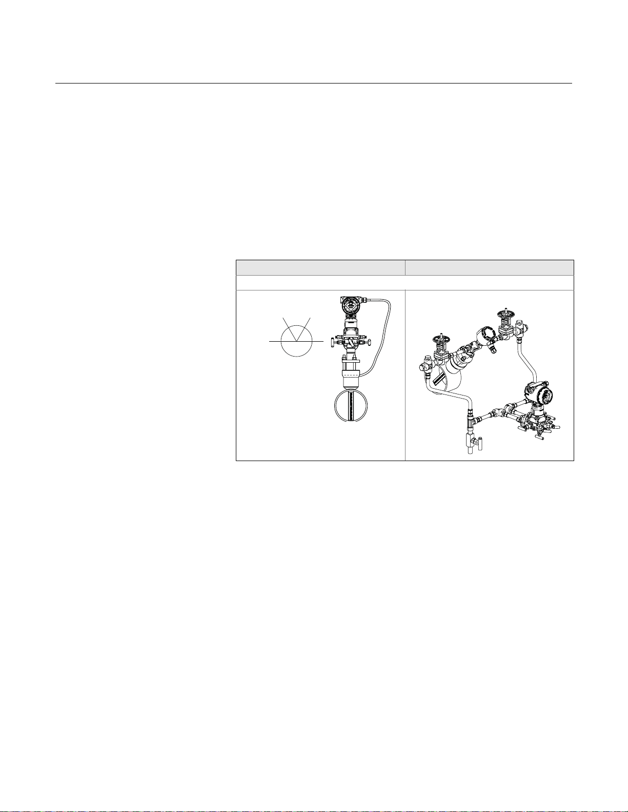
Flowmeter Orientation Liquid
Due to the possibility of air getting trapped in the Annubar sensor , it should
be located according to Figure 2-5 for liquid applications. It should be
mounted between 15° to 45° from vertical down to ensure that air is vented
from the Annubar , and that sediment or solid particle s are not collect within
the Annubar.
For liquid applications, mou nt the side drain/vent valve up ward to allow the
gases to vent. In vertical lines, the Annubar sensor can be installed in any
position around the circumference of the pipe, provided the vents are
positioned properly for bleeding or venting. Vertical pipe installations
require more frequent bleeding or venting, depe nding on the location.
For a remote mounted transmitter, mount the transmitter below the
process piping, adjust 10° to 15° above direct vertical down. Route the
impulse piping down to the transmitter and fill the system with cool water
through the two cross fittings.
Reference Manual
00809-0100-4809, Rev CB
March 2012
Figure 2-5. Liquid Applications
Direct Mount
Horizontal Liquid Vertical Liquid
Remote Mount
Horizontal Liquid Vertical Liquid
2-10
Page 11

Reference Manual
45°45°
Recommended
Zone 90°
360°
Flow
00809-0100-4809, Rev CB
March 2012
Annubar Flowmeter Series
Gas
Figure 2-6 illustrates the recommended location of the flowmeter in gas
applications. The sensor should be located on the upper half of the pipe, at
least 45° above the horizontal line.
For gas applications, mount the drain/vent valve downward to allow liquid
to drain. In vertical lines, the Annubar sensor can be installed in any
position around the circumference of the pipe, provided the vents are
positioned properly for bleeding or venting. Vertical pipe installations
require more frequent bleeding or venting, depe nding on the location.
For a remote mounted transmitter, secure the transmitter above the
Annubar sensor to prevent condensable liquids from collecting in the
impulse piping and the DP cell.
Figure 2-6. Gas Applications
Direct Mount
Horizontal Gas Vertical Gas
Remote Mount
Horizontal Gas Vertical Gas
2-11
Page 12

Annubar Flowmeter Series
30°
Recommended
Zone 30°
Recommended
Zone 30°
45° 45°
360°
Flow
Steam
In steam applications, fill the lines with water to prevent the steam from
contacting the transmitter. Condensate chambers are not required
because the volumetric displacement of the transmitter is negligible.
For a remote mounted transmitter, mount the transmitter below the
process piping, adjust to 10° to 15° above direct vertical down. Route the
impulse piping down to the transmitter and fill the system with cool water
through the two cross fittings.
Figure 2-7 illustrates the recommended location of the flowmeter in steam
applications.
Reference Manual
00809-0100-4809, Rev CB
March 2012
Figure 2-7. Steam Applica tions
Direct Mount
Horizontal Steam Vertical Steam
Note: Downward flow is not recommented.
Remote Mount
Horizontal Steam Vertical Steam
2-12
Page 13
Reference Manual
60°
Recommended Zone
60° 60°
00809-0100-4809, Rev CB
March 2012
Figure 2-8. Top Mounting for
Steam
Annubar Flowmeter Series
Top Mounting for Steam
This orientation can be used for any steam temperature. However, it is
recommended for installations above 600 °F (315 °C). For remote mount
installations, the impulse piping should slope up slightly from the instrument
connections on the Annubar to the cross fittings, allowing condensate to drain
back into the pipe. From the cross fittings, the impulse piping should be ro uted
downward to the transmitter and the drain legs. The transmitter should be
located below the instrument connections of the Annubar. Depending on the
environmental conditions, it may be necessary to insulate the mounting
hardware. The temperature limit for top mountin g a Dire ct Mou nt flowme ter is
400 °F (205 °C).
Direct Mount Remote Mount
Horizontal Top Mounting for Steam
Remote Mounted
Transmitter
NOTE
For wet steam, do not mount the flowmeter at the
direct vertical position. Mounting at an angle will
avoid measurement inaccuracy due to water
running along the bottom of the pipe.
Instrument head connections differ between horizo nt al and vertical pipes. For
horizontal lines, the instrument connections are parallel to the pipe and for
vertical lines, the instrument connection ar e pe rp e ndi cu lar.
Valves and Fittings
Throughout the remote mounting process:
• Use only valves, fittings, and pipe thread sealant compounds that are
rated for the service pipeline design pressure and temperature as
specified in Appendix A: Specifications and Reference Data.
• Verify that all connections are tight and that all instrument valves are
fully closed.
• Verify that th e Annubar sensor is properly oriented for the intended type
of service: liquid, gas, or steam (see “Flowmeter Orientation” on
page 2-10).
2-13
Page 14

Annubar Flowmeter Series
Impulse Piping
Impulse piping connects a remote mounted tra nsmitter to the Annubar se nsor .
Temperatures in excess of 250 °F (121 °C) at the transmitter will damage
electronic components; impulse piping allows service flow temperatures to
decrease to a point where the transmitter is no longer vulnerable.
The following restrictions and recommendations apply to impulse piping
location.
• Piping used to connect the Annubar sensor and transmitter must be
rated for continuous operation at the pipeline-designed pressure and
temperature.
• Impulse piping that runs horizontally must slope at least 1–in. per foot
(83 mm/m).
• With the Annubar mounted below the pipe, impulse piping must slope
downwards (toward the transmitter) for liquid and steam applications.
• With the Annubar mounted above the pipe, impulse piping must slope
up (toward from the transmitter) for gas and top mount steam
applications.
• For applications where the pipeline temperature is below 250 °F
(121 °C), the impulse piping should be as short as possible to minimize
flow temperature changes. Insulation may be required.
• For applications where pipeline temperature is above 250 °F (121 °C),
the impulse piping should have a minimum length of 1-ft. (0.30 m) for
every 100 °F (38 °C) over 250 °F (121 °C), which is the maximum
operating transmitter temperature. Impulse piping must be uninsulated
to reduce fluid temperature. All threaded connections should be
checked after the system comes up to temperature, beca u se
connections may be loosened by the expansion and contraction
caused by temperature changes.
• A minimum of
with a wall thickness of at least 0.035-in. is recommended.
• Outdoor installations for liquid, saturated gas, or steam service may
require insulation and heat tracing to preven t fre e zing .
• For installations where the transmitter is more than 6-ft. (1.8m) from the
Annubar sensor, the high and low impulse piping must be run together
to maintain equal temperature. They must be supported to prevent
sagging and vibration.
• Threaded pipe fittings are not recomme nded because they create voids
where air can become entrapped and have more possibilities for
leakage.
• Run impulse piping in protected areas or against walls or ceilings. If the
impulse piping is run across the floor, ensure that it is protected with
coverings or kick plates. Do not locate the impulse piping near high
temperature piping or equipment.
• Use an appropriate pipe sealing compound rated for the service
temperature on all threaded connections. When making threaded
connections between stainless steel fittings, Loctite
recommended.
Reference Manual
00809-0100-4809, Rev CB
March 2012
1
/2-in. (12mm) outer diameter (OD) stainless steel tubing
®
PST® Sealant is
2-14
Page 15

Reference Manual
Recommended Zone
30°
360°
Flow
00809-0100-4809, Rev CB
March 2012
Flo-Tap Models
Figure 2-9. Gas Service Gas
Annubar Flowmeter Series
Direct Mount
Horizontal Gas Vertical Gas
Remote Mount
Horizontal Gas Vertical Gas
2-15
Page 16

Annubar Flowmeter Series
30°
Recommended Zone
360°
Flow
Note: Downward flow is not recommented.
Liquid
Reference Manual
00809-0100-4809, Rev CB
March 2012
Figure 2-10. Liquid Service
Direct Mount
Horizontal Liquid Vertical Liquid
Remote Mount
Horizontal Liquid Vertical Liquid
2-16
Page 17

Reference Manual
30°
Recommended Zone
Flow
360°
Note: Downward flow is not recommented.
60°
Recommended Zone
60° 60°
00809-0100-4809, Rev CB
March 2012
Figure 2-11. Steam Steam
Annubar Flowmeter Series
Direct Mount
Horizontal Steam Vertical Steam
Remote Mount
Horizontal Steam Vertical Steam
Figure 2-12. Top Mounting for
Steam
Direct Mount Remote Mount
Horizontal Top Mounting for Steam
Note
For wet steam, do not mount the flowmeter at the
direct vertical position. Mounting at an angle will
avoid measurementinaccuracy due to water
running along the bottom of the pipe.
2-17
Page 18

Reference Manual
Transmitter
Compression Plate
Coplanar
Flange
with Drain
Vents
O-Rings (2)
485 Annubar Sensor
Retaining Ring
Direct Mount Transmitter
Connection with Valves
Studs
Pak-Lok Body
Packing Rings (3)
Follower
Nuts
Transmitter and
housing are shown for
clarity purposes – only
supplied if ordered.
00809-0100-4809, Rev CB
Annubar Flowmeter Series
March 2012
INSTALLATION This manual contains the horizonta l and vertical installation procedures for the
Pak-Lok, Flanged, Flange-Lok, Threaded Flo-Tap, Flanged Flo-tap, and Main
Steam Annubar models.
Pak-Lok Annubar Type
(for 485 Annubar
Flowmeters)
Figure 2-13. Components
Figure 2-13 identifies the components of the Pak-Lok assembly.
2-18
Step 1: Determine the Proper Orientation
Please refer to “Mounting” on page 2-4 for straight run requirements and
orientation information.
Page 19

Reference Manual
P/N: 28-109001-922 Rev. AC
Drill to Hole Size
Drill the appropriate
diameter hole through
the pipe wall.
Note: Drill the hole 180°
from the first hole for
opposite- side support
models.
00809-0100-4809, Rev CB
March 2012
Annubar Flowmeter Series
Step 2: Drill a Hole into the Pipe
1. Determine the drill hole size based on the Sensor Size of Sensor
Width.
2. Determine the sensor size based on the width of the Annubar. See
Table 2-3.
3. From the previous steps, select the location to drill the hole.
4. Determine the diameter of the hole to be drilled according to the
specifications in Table 2-3 and drill the hole with a hole saw or drill.
Do not torch cut the hole.
Table 2-3. 485 Sensor Size /
Hole Diameter Chart
Sensor
Size
Sensor Width Hole Diameter
1 0.590-in.
(14.99 mm)
2 1.060-in.
(26.92 mm)
3 1.935-in.
(49.15 mm)
3
/4-in.
(19 mm)
15/16-in.
(34 mm)
21/2-in.
(64 mm)
+ 1/32-in (0.8 mm)
– 0.00
+ 1/16-in. (1.6 mm)
– 0.00
+ 1/16-in. (1.6 mm)
– 0.00
5. If opposite-side support coupling is supplied, a second identically
sized hole must be drilled opposite the first hole so that the sensor
can pass completely through the pipe. (To determine an opposite-side
support model, measure the distance from the tip of the first slot or
hole. If the distance is greater than 1-in. (25.4 mm), it is the
opposite-side model.) To drill the second hole, follow these steps:
a. Measure the pipe circumference with a pipe tap e, sof t wire, or string
(for the most accurate measurement the pipe tape needs to be
perpendicular to the axis of flow).
b. Divide the measured circumference by two to determin e the location
of the second hole.
c. Rewrap the pipe tape, soft wire, or string from the center of the first
hole. Then, using the number calculated in the preceding step, mark
the center of what will become the second hole.
d. Using the diameter determined from Table 2-3, drill the hole into the
pipe with a hole saw or drill. Do not torch cut the hole.
6. Deburr the drilled hole(s) on the inside of the pipe.
2-19
Page 20

Annubar Flowmeter Series
LMH
(1)
Tack
Welds
Serial No. Date
Model
Customer T ag
Pipe I.D. Wall
Max. Allow FlowRate
Max. Insert/Retract Flow
Max. Press. @ Temp
Span (20mA)
00-370000-2X1 Rev. AC
Step 3: Weld the Mounting Hardware
1. Center the Pak-Lok body over the mounting hole, gap
and place four
2. Check alignment of the Pak-Lok body both p arallel a nd perpendicu lar
to the axis of flow. If alignment of mounting is within tolerances (see
Figure 2-14), finish weld per local codes. If alignment is outside of
specified tolerance, make adjustments prior to finish weld.
Figure 2-14. Alignment
Reference Manual
00809-0100-4809, Rev CB
1
1
/4-in. (6-mm) tack welds at 90° increments.
/16-in. (1.5 mm)
March 2012
3. If opposite side support is being used, center the fitting for the
1
opposite side support over the opposite side hole, gap
1
mm) and place four
/4-in. (6 mm) tack welds at 90° increments. Insert
/16-in. (1.5
the sensor into the mounting hardware. Verify that the tip of the bar is
centered in the opposite side fitting and verify that the plug will fit
around bar . If the ba r is cen tered in the fitting and plug fits around the
bar, finish weld per local cod es. If the alignment of the bar does not
allow enough clearance to insert the opposite side plug, make the
necessary adjustments prior to making the finish weld.
4. To avoid serious burns, allow the mounting hardware to cool before
continuing.
Step 4: Insert Annubar
After the mounting hardware has cooled, use the following steps for
installation.
1. Thread studs into the Pak-Lok body.
2. To ensure that the flowmeter contacts the opposite side wall, mark the
tip of the sensor with a marker. (Do not mark if the sensor was
ordered with special-cleaned option code P2 or PA.)
3. Insert the flowmeter into the Pak-lok body until the sensor tip contact s
the pipe wall (or support plug). Rotate the flowmeter back and forth.
4. Remove the flowmeter.
2-20
Page 21

Reference Manual
Packing Rings (3)
Retaining Ring
Compression Plate
Follower
1. Install the first Packing Ring underneath
the Follower.
2. Use the Follower and the Compression
Plate to compress the first Packing
Ring against the Retaining Ring.
3. Install the second Packing Ring
underneath the Follower. Alternate
packing ring splits by 120 degrees to
each other.
4. Use the Follower and the Compression
Plate to compress the second Packing
Ring against the first Packing Ring.
5. Install the third Packing Ring
underneath the Follower.
6. Use the Follower and the Compression
Plate to compress the third Packing
00809-0100-4809, Rev CB
March 2012
Figure 2-15. Packing Ring Detail
Annubar Flowmeter Series
5. Verify that the sensor tip made co nt act with the pipe wall by removing
the pipe and ensuring that some of the marker has been rubbed off.
For special-cleaned Annubar sensors, look for wear marks on the tip.
If the tip did not touch the wall, verify pipe dimensions and the height
of mounting body from the outer diameter of the pipe and re-insert.
6. Align the flow arrow with the direction of flow. Re-insert the flowmeter
into the Pak-Lok body and install the first packing ring on the sensor
between the lock ring and the packing follower. Take care not to
damage the split packing rings.
7. Push the packing ring into the Pak-Lok body and against the weld
lock ring. Repeat this process for the two remaining rings, alternating
the location of the packing ring split by 180°.
8. Tighten the nuts onto the studs:
• Place the included split-ring lock washer between each of the nuts
and the compression plate. Give each nut one half (
succession until the split-ring lock washer is flat between the nut
NOTE
On sensor size (1), failure to use the split-ring lock washers, improper wash er
orientation, or over-tightening the nuts may result in damage to the flowmeter.
and the compression plate.
Sensor Size Torque
• Inspect the unit for leakage; if any exists, tighten the nuts in
one-quarter (
1 40-in. / lb (4.52 Nm)
2 100-in. / lb (11.30 Nm)
3 250-in. / lb (28.25 Nm)
1
/4) turn increments until there is no leakage.
1
/2) turn in
2-21
Page 22

Annubar Flowmeter Series
Before Tightening After Tightening
Split ring
lock washer
Nut
Stud
Compression
Plate
Split ring
lock washer
Nut
Stud
Compression
Plate
GAP
WELD RING
FOLLOWER
(3) P ACKING
RINGS
Figure 2-16. Split-Ring Lock
Washer Orientation
NOTE
Pak-Lok sealing mechanisms generate significant force at the poin t where the
sensor contacts the opposite pipe wall. Caution needs to be exercised on
thin-walled piping (ANSI Schedule 10 and below) to avoid damage to the
pipe.
Reference Manual
00809-0100-4809, Rev CB
March 2012
Figure 2-17. Complete
installation of Pak-lok
Figure 2-17 shows a view of the Pak-lok Annubar when installation is
completed. Please note that there should be a gap between the Pak-lok Body
and the Weld Ring.
Step 5: Mount the Transmitter
Direct Mount Head
With Valves
• Place PTFE O-rings into grooves on the face of head.
• Align the high side of the transmitter to the high side of the pr ob e
(“Hi” is stamped on the side of the head) and install.
• Tighten the nuts in a cross pattern to 400 in-lb (45 N-m).
2-22
Page 23

Reference Manual
00809-0100-4809, Rev CB
March 2012
Annubar Flowmeter Series
Without Valves
• Place PTFE O-rings into grooves on the face of head.
• To install a manifold, orient the equalizer valve or valves so they are
easily accessible. Install manifold with the smooth face mating to the
face of the head. Tighten in cross pattern to a torque of 400 in-lb (45
N-m).
• Place PTFE O-rings into grooves on the face of the manifold.
• Align the high side of the transmitter to the high side of the pr ob e
(“Hi” is stamped on the side of the head) and install.
• Tighten the nuts in a cross pattern to 400 in-lb (45 N-m).
2-23
Page 24

Annubar Flowmeter Series
Transmitter
Sensor Flange
Coplanar Flange with
Drain Vents
O-Rings (2)
485 Annubar Sensor
Mounting Flange Assembly
Direct Mount Transmitter
Connection with Valves
Studs
Gasket
Nuts
Opposites Side Support
Transmitter and housing
are shown for clarity
purposes – only supplied
if ordered.
Reference Manual
00809-0100-4809, Rev CB
March 2012
Flanged with Opposite
Side Support Annubar
Type (for 485 and 585
Annubar Flowmeters)
Figure 2-18. Components
Figure 2-18 identifies the components of the Flanged assembly.
Step 1: Determine the Proper Orientation
Please refer to “Mounting” on page 2-4 for straight run requirements and
orientation information.
2-24
Page 25

Reference Manual
Drill the appropriate
diameter hole through
the pipe wall.
Note: Drill the hole 180°
from the first hole for
opposite- side support
models.
Drill the appropriate
diameter hole through
the pipe wall.
Note: Drill the hole 180°
from the first hole for
opposite- side support
models.
00809-0100-4809, Rev CB
March 2012
Annubar Flowmeter Series
Step 2: Drill a Hole into the Pipe
1. Determine the drill hole size based on the Sensor Size of Sensor
Width.
2. Depressurize and drain the pipe.
3. From the previous steps, select the location to drill the hole.
4. Determine the diameter of the hole to be drilled according to the
specifications in Table 2-1 and drill the hole with a hole saw or a drill.
Do not torch cut the hole.
Table 2-1. 485 Sensor Size/
Hole Diameter Chart
Table 2-2. 585 Sensor Size/
Hole Diameter Chart
SensorSize Sensor Wid th Hole Diameter
3
1 0.590-in.
(14.99 mm)
2 1.060-in.
(26.92 mm)
3 1.935-in.
(49.15 mm)
Sensor Size Sensor Width Hole Diameter
11 0.80-in.
(20.32 mm)
22 1.20-in.
(30.48 mm)
44 2.30-in. 2
(58.42 mm)
/4-in.
(19 mm)
15/16-in.
(34 mm)
1
/2-in.
2
(64 mm)
7
/8-in.
(23 mm)
15/16-in.
(34 mm)
1
/2-in. +
(64 mm)
+ 1/32-in (0.8 mm)
– 0.00
+ 1/16-in. (1.6 mm)
– 0.00
+ 1/16-in. (1.6 mm)
– 0.00
1
+
/32-in (0,8 mm)
– 0.00
+ 1/16-in. (1,6 mm)
– 0.00
1
/16-in. (1,6 mm)
– 0.00
5. If opposite-side support coupling is supplied, a second identically
sized hole must be drilled opposite the first hole so that the sensor
can pass completely through the pipe. To drill the second hole, follow
these steps:
a. Measure the pipe circumference with a pipe tap e, sof t wire, or string
(for the most accurate measurement the pipe tape needs to be
perpendicular to the axis of flow).
b. Divide the measured circumference by two to determin e the location
of the second hole.
c. Rewrap the pipe tape, soft wire, or string from the center of the first
hole. Then, using the number calculated in the preceding step, mark
the center of what will become the second hole.
d. Using the diameter determined from Table 2-1, drill the hole into the
pipe with a hole saw or drill. Do not torch cut the hole.
6. Deburr the drilled holes on the inside of the pipe.
2-25
Page 26

Annubar Flowmeter Series
The
same
within
1
/8-in.
(3 mm)
Pipe Outside
Diameter
Port A
Port B
ODF
Step 3: Assemble and check Fit-Up
For accurate measurement, use the following step s to ensure that Port s A and
B are equal distances from the inside walls of the pipe.
1. Assemble the Annubar sensor to the mounting hardware with the
gaskets and bolts.
2. Hand tighten the bolts just enough to hold the position of the sensor
centered in the mounting hardware.
3. Measure the distance from the high point of the weldolet to the first
sensing hole, port B, then subtract
4. Measure the distance from the end of the transferred length in step 3
to the last sensing hole, port A.
5. Compare the numbers obtained in steps 3 and 4.
Small discrepancies can be compensated for with the fit-up of the mounting
hardware. Large discrepancies may cause installation problems or error.
Figure 2-19. Fit-up Check for
Annubar with Opposite Side
Support
Reference Manual
00809-0100-4809, Rev CB
1
/16-in. (1.6 mm).
March 2012
2-26
Step 4: Weld the Mounting Hardware
1. Center the Flanged body over the mounting hole, gap
and measure the distance from the out side diameter of the pipe to the
face of the flange. Compare this to the table below and adjust the gap
as necessary.
1
/16-in. (1.5 mm)
Page 27

Reference Manual
00809-0100-4809, Rev CB
March 2012
Annubar Flowmeter Series
Table 2-3. 485 and 585 Flange Sizes and ODF Per Sensor Size
485 Sensor
Size
(1) Tolerances for the ODF dimension above a 10-in. (254 mm) line size is ±0.060-in. (1,6 mm). Below
585 Sensor
Size
1 11
2 22
3 44
10-in. (254 mm) line size is ±0.030-in. (0,8 mm).
Flange Type Pressure Class
A 1 11/2-in. 150# RF 3.88 (98.6)
R 1 11/2-in. 150# RTJ 4.06 (103.1)
D 1 DN40 PN16 RF 3.21 (81.5)
A 1 2.0-in. 150# RF 4.13 (104.9)
R 1 2.0-in. 150# RTJ 4.31 (119.5)
D 1 DN50 PN16 RF 3.40 (86.4)
A 1 3.0-in. 150# RF 4.63 (117.6)
R 1 3.0-in. 150# RTJ 4.81 (122.2)
D 1 DN80 PN16 RF 3.85 (97.8)
Flange Size / Rating
/ Type
3 11/2-in. 300# RF 4.13 (104.9)
6 11/2-in. 600# RF 4.44 (112.8)
N / 9 11/2-in. 900# RF 4.94 (125.5)
F 11/2-in. 1500# RF 4.94 (125.5)
T 11/2-in. 2500# RF 6.76 (171.7)
3 11/2-in. 300# RTJ 4.31 (109.5)
6 11/2-in. 600# RTJ 4.44 (112.8)
N / 9 11/2-in. 900# RTJ 4.94 (125.5)
F 11/2-in. 1500# RTJ 4.94 (125.5)
T 11/2-in. 2500# RTJ 6.81 (173.0)
3 DN40 PN40 RF 3.21 (81.5)
6 DN40 PN100 RF 3.88 (98.6)
3 2.0-in. 300# RF 4.38 (111.3)
6 2.0-in. 600# RF 4.75 (120.7)
N / 9 2.0-in. 900# RF 5.88 (149.4)
F 2.0-in. 1500# RF 5.88 (149.4)
T 3.0-in. 2500# RF 9.88 (251.0)
3 2.0-in. 300# RTJ 4.63 (117.6)
6 2.0-in. 600# RTJ 4.81 (122.2)
N 2.0-in. 900# RTJ 5.94 (150.9)
F 2.0-in. 1500# RTJ 5.94 (150.9)
T 3.0-in. 2500# RTJ 10.00 (254.0)
3 DN50 PN40 RF 3.52 (89.4)
6 DN50 PN100 RF 4.30 (109.5)
3 3.0-in. 300# RF 5.00 (127.0)
6 3.0-in. 600# RF 5.38 (136.7)
N / 9 4.0-in. 900# RF 8.19 (208.0)
F 4.0-in. 1500# RF 8.56 (217.4)
T 4.0-in. 2500# RF 11.19 (284.2)
3 3.0-in. 300# RTJ 5.25 (133.4)
6 3.0-in. 600# RTJ 5.44 (138.2)
N / 9 4.0-in. 900# RTJ 8.25 (209.6)
F 4.0-in. 1500# RTJ 8.63 (219.2)
T 4.0-in. 2500# RTJ 11.38 (289.1)
3 DN80 PN40 RF 4.16 (105.7)
6 DN80 PN100 RF 4.95 (125.7)
ODF in. (mm)
(1)
2. Place four 1/4-in. (6-mm) tack welds at 90° increments. Check
alignment of the mounting both parallel and perpendicular to the axis
of flow (see Figure 2-20). If alignment of the mounting is within
tolerances, finish weld per local codes. If alignment is outside of
specified tolerance, make adjustments prior to making the finish weld.
2-27
Page 28

Annubar Flowmeter Series
ODF
Tack Welds
Figure 2-20. Alignment
Reference Manual
00809-0100-4809, Rev CB
March 2012
3. Center the fitting for the opposite side support over the opposite side
1
hole, gap
/16-in. (1.5 mm) and place four 1/4-in. (0.5 mm) tack welds at
90° increments. Insert the sensor into the mounting hardware. Verify
that the tip of the bar is centered in the opposite side fitting and that
the plug will fit around bar. If the sensor is centered in the fitting and
plug fits around the sensor, finish weld per local codes. If alignment of
the sensor does not allow enough clearance to insert the opposite
side plug, make the necessary adjustments prior to making the finish
weld.
4. To avoid serious burns, allow the mounting hardware to cool
before continuing.
Step 5: Insert the Annubar Sensor
1. If opposite side support is threaded, apply an appropriate thread
sealing compound to the support plug threads and tighten until no
leakage occurs.
2. Align the flow arrow on the head with the direction of flow. Assemble
the Annubar to the mounting flange using a gasket, bolts, and nuts.
3. If opposite side support is a socket weld fitting, insert the plug into the
1
sockolet fitting until the parts contact. Retract the plug
/16-in. (1.5
mm), remove the Annubar sensor and apply fillet weld per local
codes.
4. Tighten the nuts in a cross pattern to allow even compression of the
gasket.
2-28
Step 6: Mount the Transmitter
Direct Mount Head
With Valves
1. Place PTFE O-rings into grooves on the face of head.
2. Align the high side of the transmitter to the high side of the probe
(“Hi” is stamped on the side of the head) and install.
3. Tighten the nuts in a cross pattern to 400 in-lb (45 N-m).
Page 29

Reference Manual
Transmitter
Compression Plate
Coplanar Flange with
Drain Vents
O-Rings (2)
485 Annubar Sensor
Flange-Lok Assembly
Direct Mount Transmitter
Connection with Valves
Studs
Gasket
Nuts
Mounting Flange Assembly
Packing Rings (3)
Follower
Transmitter and housing
are shown for clarity
purposes – only supplied if
ordered.
00809-0100-4809, Rev CB
March 2012
Annubar Flowmeter Series
Without Valves
1. Place PTFE O-rings into grooves on the face of head.
2. To install a manifold, orient the equalizer valve or valves so they are
easily accessible. Install manifold with the smooth face mating to the
face of the head. Tighten in cross patte rn to a torque of 400 in-lb (45
N-m).
3. Place PTFE O-rings into grooves on the face of the manifold.
4. Align the high side of the transmitter to the high side of the probe
(“Hi” is stamped on the side of the head) and install.
5. Tighten the nuts in a cross pattern to 400 in-lb (45 N-m).
Flange-Lok Model (for
485 Annubar
Flowmeters)
Figure 2-21. Components
Figure 2-21 identifies the components of the Flange-L ok assembly.
2-29
Page 30

Annubar Flowmeter Series
Drill the appropriate
diameter hole through
the pipe wall.
Note: Drill the hole 180°
from the first hole for
opposite- side support
models.
Step 1: Determine the Proper Orientation
Please refer to “Mounting” on page 2-4 for straight run requirements and
orientation information.
Step 2: Drill a Hole into the Pipe
1. Determine the drill hole size based on the Sensor Size of Sensor
Width.
2. Depressurize and drain the pipe.
3. Select the location to drill the hole.
4. Determine the diameter of the hole to be drilled according to the
specifications in Table 2-4 and drill the hole with a hole saw or a drill.
Do not torch cut the hole.
Reference Manual
00809-0100-4809, Rev CB
March 2012
Table 2-4. Drill Hole into Pipe
SensorSize Sensor Width Hole Diameter
3
1 0.590-in.
(14.99 mm)
2 1.060-in.
(26.92 mm)
3 1.935-in.
(49.15 mm)
/4-in.
(19 mm)
15/16-in.
(34 mm)
1
/2-in.
2
(64 mm)
+ 1/32-in (0.8 mm)
– 0.00
+ 1/16-in. (1.6 mm)
– 0.00
+ 1/16-in. (1.6 mm)
– 0.00
5. If opposite-side support coupling is supplied, a second identically
sized hole must be drilled opposite the first hole so that the sensor
can pass completely through the pipe. (To determine an opposite-side
support model, measure the distance from the tip of the first slot or
hole. If the distance is greater than 1-in. (25.4 mm), it is the
opposite-side model.) To drill the second hole, follow these steps:
a. Measure the pipe circumference with a pipe tap e, sof t wire, or string
(for the most accurate measurement the pipe tape needs to be
perpendicular to the axis of flow).
b. Divide the measured circumference by two to determin e the location
of the second hole.
c. Rewrap the pipe tape, soft wire, or string from the center of the first
hole. Then, using the number calculated in the preceding step, mark
the center of what will become the second hole.
d. Using the diameter determined from Table 2-4, drill the hole into the
pipe with a hole saw or drill. Do not torch cut the hole.
6. Deburr the drilled hole or holes on the inside of the pipe.
2-30
Page 31

Reference Manual
00809-0100-4809, Rev CB
March 2012
Annubar Flowmeter Series
Step 3: Weld the Mounting Hardware
1. Center the Flange-Lok body over the mounting hole, gap
mm) and measure the distance from the OD of the pipe to the face of
the flange. Compare this to the table below and adjust the gap as
necessary.
Table 2-5. 485 and 585 Flange Sizes and ODF Per Sensor Size
Flange Size / Rating
485 Sensor Size Flange Type Pressure Class
1 A 1 11/2-in. 150# RF 3.88 (98.6)
3 11/2-in. 300# RF 4.13 (104.9)
6 11/2-in. 600# RF 4.44 (112.8)
N 11/2-in. 900# RF 4.94 (125.5)
F 11/2-in. 1500# RF 4.94 (125.5)
T 11/2-in. 2500# RF 6.76 (171.7)
R 1 11/2-in. 150# RTJ 4.06 (103.1)
3 11/2-in. 300# RTJ 4.31 (109.5)
6 11/2-in. 600# RTJ 4.44 (112.8)
N 11/2-in. 900# RTJ 4.94 (125.5)
F 11/2-in. 1500# RTJ 4.94 (125.5)
T 11/2-in. 2500# RTJ 6.81 (173.0)
D 1 DN40 PN16 RF 3.21 (81.5)
3 DN40 PN40 RF 3.21 (81.5)
6 DN40 PN100 RF 3.88 (98.6)
2 A 1 2.0-in. 150# RF 4.13 (104.9)
3 2.0-in. 300# RF 4.38 (111.3)
6 2.0-in. 600# RF 4.75 (120.7)
N 2.0-in. 900# RF 5.88 (149.4)
F 2.0-in. 1500# RF 5.88 (149.4)
T 3.0-in. 2500# RF 9.88 (251.0)
R 1 2.0-in. 150# RTJ 4.31 (119.5)
3 2.0-in. 300# RTJ 4.63 (117.6)
6 2.0-in. 600# RTJ 4.81 (122.2)
N 2.0-in. 900# RTJ 5.94 (150.9)
F 2.0-in. 1500# RTJ 5.94 (150.9)
T 3.0-in. 2500# RTJ 10.00 (254.0)
D 1 DN50 PN16 RF 4.63 (117.6)
3 DN50 PN40 RF 5.00 (127.0)
6 DN50 PN100 RF 5.38 (136.7)
3 A 1 3.0-in. 150# RF 4.63 (117.5)
3 3.0-in. 300# RF 5.00 (126.9)
6 3.0-in. 600# RF 5.38 (136.6)
R 1 3.0-in. 150# RTJ 4.81 (122.2)
3 3.0-in. 300# RTJ 5.25 (133.4)
6 3.0-in. 600# RTJ 5.44 (138.2)
D 1 DN80 PN16 RF 3.85 (97.8)
3 DN80 PN40 RF 4.16 (105.7)
6 DN80 PN100 RF 4.95 (125.7)
(1) Tolerances for the ODF dimension above a 10-in. (254 mm) line size is ±0.060-in. (1,6 mm).
Below 10-in. (254 mm) line size is ±0.030-in. (0,8 mm).
/ Type
1
/16-in. (2
ODF in. (mm)
(1)
2-31
Page 32

Annubar Flowmeter Series
ODF
Tack Welds
2. Place four 1/4-in. (6-mm) tack welds at 90° increments. Check
alignment of the mounting both parallel and perpendicular to the axis
of flow (see Figure 2-22). If alignment of the mounting is within
tolerances, finish weld per local codes. If outside of specified
tolerance, make adjustments prior to making the finish weld.
Figure 2-22. Alignment
Reference Manual
00809-0100-4809, Rev CB
March 2012
3. If opposite side support is being used, center the fitting for the
1
opposite side support over the opposite side hole, gap
1
mm) and place four
/4-in. (6-mm) tack welds at 90° increments. Insert
/16-in. (1.5
the sensor into the mounting hardware. Verify that the tip of the bar is
centered in the opposite side fitting and that the plug will fit around the
bar. If the sensor is centered in the fitting and plug fits around the
sensor, finish weld per local codes. If alignment of the sensor does
not allow enough clearance to insert the opposite side plug, make the
necessary adjustments prior to making the finish weld. The Annubar
sensor must be removed before welding or installing the opposite
side support plug.
4. To avoid serious burns, allow the mounting hardware to cool
before continuing.
Step 4: Insert into Pipe
1. After the mounting hardware has cooled, use the following steps for
installation.
2. Assemble the sensor flange to the mounting flange using gasket,
studs, and nuts.
3. Tighten the nuts in a cross pattern to allow even compression of
the gasket.
4. Thread studs into Flange-Lok body.
5. To ensure that the flowmeter contacts the opposite side wall, mark the
tip of the sensor with a marker. (Do not mark if the sensor was
ordered with special-cleaned option code P2 or PA.)
6. Insert the flowmeter into the Flange-lok body until the sensor tip
contacts the pipe wall (or support plug), rotating back and forth.
7. Remove the flowmeter.
2-32
Page 33

Reference Manual
Packing Rings (3)
Retaining Ring
Compression Plate
Follower
00809-0100-4809, Rev CB
March 2012
Figure 2-23. Packing Ring Detail
Annubar Flowmeter Series
8. Verify that the sensor tip made contact with the pipe wall by ensuring
that some of the marker has been rubbed off. For special-cleaned
bars, look for wear marks on the tip. If the tip did not touch the wall,
verify pipe dimensions and the height of the mounting body from the
OD of the pipe and re-insert.
9. Re-insert the flowmeter into the Flange-Lok body and install the first
packing ring on the sensor between the lock ring and the packing
follower. Take care not to damage the split packing rings.
10. Push the packing ring into the Flange-Lok body and against the weld
retaining ring. Repeat this process for the two remaining rin gs,
alternating the location of the packing ring split b y 180°.
11. Tighten the nuts onto the studs:
a. Place the included split-ring lock washer between each of the nuts
1
and the compression plate. Give each nut one half (
/2) turn in
succession until the split-ring lock washer is flat between the nut
and the compression plate. Torque is as follows:
Sensor Size Torque
1 40-in. / lb (4.52 Nm)
2 100-in. / lb (11.30 Nm)
3 250-in. / lb (28.25 Nm)
b. Inspect the unit for leakage; if any exists, tighten the nuts in
1
one-quarter (
/4) turn increments until there is no leakage.
NOTE
On sensor size (1), failure to use the split-ring Lock washers, improper
washer orientation, or over-tightening the nuts may result in damage to the
flowmeter.
2-33
Page 34

Annubar Flowmeter Series
Before Tightening After Tightening
Split ring
lock washer
Nut
Stud
Compression
Plate
Split ring
lock washer
Nut
Stud
Compression
Plate
GAP
WELD RING
FOLLOWER
(3) P ACK ING
RINGS
Figure 2-24. Split-Ring Lock
Washer Orientation
NOTE
Flange-Lok sealing mechanisms generate significant force at the po int wh ere
the sensor contacts the opposite pipe wall. Caution needs to be exercised on
thin-walled piping (ANSI Schedule 10 and below) to avoid damage to the
pipe.
Figure 2-25. Complete
installation of Flange-lok
Reference Manual
00809-0100-4809, Rev CB
March 2012
2-34
Figure 2-25 shows a view of the Flange-lok Annubar when installation is
completed. Please note that there should be a gap between the Flange-lok
Body and the Weld Ring.
Page 35

Reference Manual
Transmitter
Temperature Sensor
Connection Housing
Direct Mount Transmitter
Connection with Valves
Cage Nipple
O-Rings (2)
Head Plate
Drive Rods
Threaded
Pipe Fitting
Guide Nipple
Isolation Valve
Support Plate
Packing Gland
Packing
Follower
Compression
Plate
Coplanar Flange
with Drain Vents
Transmitter and
housing are shown
for clarity purposes
– only supplied if
ordered.
00809-0100-4809, Rev CB
March 2012
Annubar Flowmeter Series
Step 5: Mount the Transmitter
Direct Mount Head
With Valves
1. Place PTFE O-rings into grooves on the face of head.
2. Align the high side of the transmitter to the high side of the Annubar
(“Hi” is stamped on the side of the head) and install.
3. Tighten the nuts in a cross pattern to 400 in-lb (45 N-m).
Without Valves
1. Place PTFE O-rings into grooves on the face of head.
2. To install a manifold, orient the equalizer valve or valves so they are
easily accessible. Install manifold with the smooth face mating to the
face of the head. Tighten in cross patte rn to a torque of 400 in-lb (45
N-m).
3. Place PTFE O-rings into grooves on the face of the manifold.
4. Align the high side of the transmitter to the high side of the Annubar
(“Hi” is stamped on the side of the head) and install.
5. Tighten the nuts in a cross pattern to 400 in-lb (45 N-m).
Threaded Flo-Tap (for
485 Annubar Flowmeter)
Figure 2-26. Components
Figure 2-26 identifies the components of the Threaded Flo- Tap assembly.
2-35
Page 36

Annubar Flowmeter Series
LMH
Tack
Weld
Step 1: Determine the Proper Orientation
Please refer to “Mounting” on page 2-4 for straight run requirements and
orientation information.
Step 2: Weld the Mounting Hardware
NOTE
Rosemount-supplied mounting includes critical alignment hardware that
assists in the correct drilling of the mounting hole. This significantly reduces
problems encountered during insertion.
1. At the pre-determined position, pl ace the threadolet on the pipe, gap
1
/16 in. (16 mm) and place four 1/4-in. (6-mm) tack welds at 90°
increments.
2. Check alignment of the mounting both parallel and perpendicular to
the axis of flow. If the mounting alignment is within tolerances, finish
weld per local codes. If outside of tolerances, make adjustments prior
to making the finish weld.
3. To avoid serious burns, allow mounting hardware to cool before
continuing.
Reference Manual
00809-0100-4809, Rev CB
March 2012
Figure 2-27. Alignment
Step 3: Install the Isolation Valve
1. Thread the guide nipple into the mounting.
2. Thread the isolation valve into the guide nipple, ensuring that the
valve stem is positioned so that when the Flo-Tap is installed, the
insertion rods will straddle the pipe and the valve handle will be
centered between the rods (see Figure 2-28).
NOTE:
Interference will occur if the valve is located inline with the insertion rods.
2-36
Page 37

Reference Manual
Isolation Valve
Pressure
Drilling
Machine
Isolation Valve is
fully open when
inserting drill
Isolation Valve is
fully closed after
withdrawing drill
00809-0100-4809, Rev CB
March 2012
Figure 2-28. Install the Isolation
Valve
Annubar Flowmeter Series
Step 4: Mount the Drilling Machine and Drill Hole
Drilling Machine is not provided with the assembly.
1. Determine the drill hole size based on the sensor size or sensor
width.
2. Mount the drilling machine to the isolation valve.
3. Open the valve fully.
4. Drill the hole into the pipe wall in accordance with the instructions
provided by the drilling machine manufacturer.
5. Fully retract the drill beyond the valve.
Table 2-6. Sensor Size / Hole
Diameter Chart
Sensor
Size
1 0.590-in.
2 1.060-in.
3 1.935-in.
Sensor
Width
(14.99 mm)
(26.92 mm)
(49.15 mm)
Hole Diameter
3
/4-in.
(19 mm)
15/16-in.
(34 mm)
1
/2-in.
2
(64 mm)
+ 1/32-in
(0.8 mm)
– 0.00
+ 1/16-in.
(1.6 mm)
– 0.00
+ 1/16-in.
(1.6 mm)
– 0.00
Step 5: Remove the Drilling Machine
Follow these steps to remove the drilling machine:
1. Verify that the drill has been fully retracted past the valve.
2. Close the isolation valve to isolate the process.
3. Bleed drilling machine pressure and remove.
4. Check isolation valve and mounting for leakage.
2-37
Page 38

Annubar Flowmeter Series
Isolation Valve
Support Plate
Step 6: Mount the Annubar
1. Install the complete Flo-Tap assembly (fully retracted) onto the
isolation valve by threading the close nipple into the valve using the
proper thread sealant compound.
2. Rotate the Flo-Tap assembly until the flow arrow on the head aligns
with the direction of flow in the pipe.
3. Ensure that the vent valves are closed before proceeding to the
next step.
4. Quickly open and close the isolation valve to pressurize the Annub ar.
Use extreme caution if the flowing medium is steam or caustic.
5. Check the entire installation for leakage. Tighten as required to stop
any connection from leaking. Repeat steps 4 and 5 until there is no
leakage.
a. If the Flo-tap comes equipped with the gear drive option, place the
NOTE
Flo-Tap Annubars have the potential to carry a large amount of weight at a
great distance from the piping, necessitating external support. The support
plate has threaded holes to assist in supporting the Annubar. Threaded holes
(3/8"-16 UNC) are provided on the support plate for external support.
Reference Manual
00809-0100-4809, Rev CB
March 2012
PVC protector rod assembly over the drive rods and attach to the
gear drive with the supplied hardware.
Figure 2-29. Flo-Tap Installation
2-38
Page 39

Reference Manual
Drive
Nuts
Lock
Nuts
Drive
Lock
Pin
00809-0100-4809, Rev CB
March 2012
Annubar Flowmeter Series
Step 7: Insert the Annubar
Insert the sensor with one of the two drive options available – manual drive
(M) or gear drive (G).
Manual (Not recommended for line sizes above 12 inches (300 mm))
1. Open the isolation valve fully.
2. Rotate drive nuts clockwise (as viewed from the top) as shown in
Figure 2-29. The nuts must be tightened alternately, about two turns
at a time to prevent binding caused by unequal loading.
3. Continue this procedure until the tip of the probe firmly contacts the
opposite side of the pipe.
a. The orange stripes are a visual indication of when the sensor is
approaching the opposite side wall.
b. As the orange stripe approaches the support plate, place a finger
above the packing gland while cranking.
1
c. Turn the drive nuts an additional
Gear Drive (G)
/4 to 1/2 turn to secure the sensor.
Figure 2-30. Insert Annubar
1. Fully open the isolation valve.
2. Rotate the crank clockwise. If a power drill with an adapter is used, do
not exceed 200 rpm.
a. Continue rotating the crank until the sensor firmly contacts the
opposite side of the pipe. The orange stripes are a visual in dication
of when the sensor is approaching the opposite side wall.
b. As the orange stripes approach the support plate, remove the
power drill and continue cranking manually. Place a finger above
the packing gland while cranking. When the movement stops, the
sensor is in contact with the opposite side wall.
1
c. Turn the handle an additional
/4 to 1/2 turn to secure the sensor.
3. Secure the drive by inserting the drive lock pin as shown in
Figure 2-30.
NOTE:
Do not place a finger above the packing gland for high temperature
applications.
Manual Drive (M) Gear Drive (G)
2-39
Page 40

Annubar Flowmeter Series
Step 8: Mount the Transmitter
Direct Mount Head
With Valves
1. Place PTFE O-rings into grooves on the Annubar head.
2. Align the high side of the transmitter to the high side of the se ns or
(“Hi” is stamped on the side of the head) and install.
3. Tighten the nuts in a cross pattern to 400 in•lb (45 N•m).
Without Valves
1. Place PTFE O-rings into grooves on the Annubar head.
2. To install a manifold, orient the equalizer valve or valves so they are
easily accessible. Install manifold with the smooth face mating to the
face of the head. Tighten in cross pattern to a torque of 400 in•lb (45
N•m).
3. Place PTFE O-rings into grooves on the face of the manifold.
4. Align the high side of the transmitter to the high side of the probe
(“Hi” is stamped on the side of the head) and install.
Reference Manual
00809-0100-4809, Rev CB
March 2012
Tighten the nuts in a cross pattern to 400 in-lb (45 N-m).
Step 9: Retract the Annubar
Manual Drive (M)
1. Retract by rotating the drive nuts counter-clockwise. The nuts must
be turned alternately, about two turns at a time, to prevent binding
caused by unequal loading.
2. Continue this procedure until the rod end nut s are against the p acking
body mechanism.
Gear Drive (G)
1. Remove the drive lock pin.
2. Retract the sensor by rotating the crank counter-clockwise. If a power
drill with an adapter is used, do not exceed 200 rpm.
3. Retract until the rod end nuts are against the p acking body
mechanism.
2-40
Page 41

Reference Manual
Transmitter
Temperature
Sensor
Connection
Housing
Direct Mount
Transmitter
Connection with
Valves
Cage Nipple
O-Rings (2)
Head Plate
Drive Rods
Mounting Flange Assembly
Gasket
Isolation Valve
Support
Plate
Packing
Gland
Packing
Follower
Compression
Plate
Coplanar Flange
with Drain Vents
Transmitter and
housing are shown
for clarity purposes
– only supplied if
ordered.
00809-0100-4809, Rev CB
March 2012
Annubar Flowmeter Series
Flanged Flo-Tap (for 485
and 585 Annubar
Flowmeters)
Figure 2-31. Components
Figure 2-31 identifies the components of the Flanged Flo-Tap assembly.
Step 1: Determine the Proper Orientation
Please refer to “Mounting” on page 2-4 for straight run requirements and
orientation information.
Step 2: Weld the Mounting Hardware
NOTE
Rosemount-supplied mounting includes critical alignment hardware that
assists in the correct drilling of the mounting hole. This significantly reduces
problems encountered during insertion.
1. At the pre-determined position, place the flanged assembly on the
pipe, gap
1
/16 in. (1,6 mm) and measure the distance from the outside
diameter of the pipe to the face of the flange. Compare this to the
chart below and adjust the gap as necessary.
2-41
Page 42

Annubar Flowmeter Series
Table 2-7. 485 and 585 Flange Sizes and ODF Per Sensor Size
485 Sensor
Size
1 11
2 22
3 44
(1) Tolerances for the ODF dimension above a 10-in. (254 mm) line size is ±0.060-in. (1,6 mm). Below
10-in. (254 mm) line size is ±0.030-in. (0,8 mm).
585 Sensor
Size
Reference Manual
00809-0100-4809, Rev CB
March 2012
Flange Size / Rating
Flange Type Pressure Class
A 1 11/2-in. 150# RF 3.88 (98.6)
3 11/2-in. 300# RF 4.13 (104.9)
6 11/2-in. 600# RF 4.44 (112.8)
N 11/2-in. 900# RF 4.94 (125.5)
F 11/2-in. 1500# RF 4.94 (125.5)
T 11/2-in. 2500# RF 6.76 (171.7)
R 1 11/2-in. 150# RTJ 4.06 (103.1)
3 11/2-in. 300# RTJ 4.31 (109.5)
6 11/2-in. 600# RTJ 4.44 (112.8)
N 11/2-in. 900# RTJ 4.94 (125.5)
F 11/2-in. 1500# RTJ 4.94 (125.5)
T 11/2-in. 2500# RTJ 6.81 (173.0)
D 1 DN40 PN16 RF 3.21 (81.5)
3 DN40 PN40 RF 3.21 (81.5)
6 DN40 PN100 RF 3.88 (98.6)
A 1 2.0-in. 150# RF 4.13 (104.9)
3 2.0-in. 300# RF 4.38 (111.3)
6 2.0-in. 600# RF 4.75 (120.7)
N 2.0-in. 900# RF 5.88 (149.4)
F 2.0-in. 1500# RF 5.88 (149.4)
T 3.0-in. 2500# RF 9.88 (251.0)
R 1 2.0-in. 150# RTJ 4.31 (119.5)
3 2.0-in. 300# RTJ 4.63 (117.6)
6 2.0-in. 600# RTJ 4.81 (122.2)
N 2.0-in. 900# RTJ 5.94 (150.9)
F 2.0-in. 1500# RTJ 5.94 (150.9)
T 3.0-in. 2500# RTJ 10.00 (254.0)
D 1 DN50 PN16 RF 3.40 (86.4)
3 DN50 PN40 RF 3.52 (89.4)
6 DN50 PN100 RF 4.30 (109.5)
A 1 3.0-in. 150# RF 4.63 (117.6)
3 3.0-in. 300# RF 5.00 (127.0)
6 3.0-in. 600# RF 5.38 (136.7)
N 4.0-in. 900# RF 8.19 (208.0)
F 4.0-in. 1500# RF 8.56 (217.4)
T 4.0-in. 2500# RF 11.19 (284.2)
R 1 3.0-in. 150# RTJ 4.81 (122.2)
3 3.0-in. 300# RTJ 5.25 (133.4)
6 3.0-in. 600# RTJ 5.44 (138.2)
N 4.0-in. 900# RTJ 8.25 (209.6)
F 4.0-in. 1500# RTJ 8.63 (219.2)
T 4.0-in. 2500# RTJ 11.38 (289.1)
D 1 DN80 PN16 RF 3.85 (97.8)
3 DN80 PN40 RF 4.16 (105.7)
6 DN80 PN100 RF 4.95 (125.7)
/ Type
ODF in. (mm)
(1)
2-42
Page 43

Reference Manual
ODF
Tack Weld
Isolation Valve
00809-0100-4809, Rev CB
March 2012
Figure 2-32. Alignment
Annubar Flowmeter Series
2. Place four 1/4-in. (6-mm) tack welds at 90° increments. Check
alignment of the mounting both parallel and perpendicular to the axis
of flow.
3. If the mounting alignment is within tolerances, finish weld per local
codes. If outside of tolerances, make adjustments prior to making th e
finish weld.
4. To avoid serious burns, allow the mounting hardware to cool
before continuing.
Figure 2-33. Install
Isolation Valve
Step 3: Install the Isolation Valve
1. Position the isolation valve onto the mounting flange. Ensur e that the
valve stem is positioned so that when the Flo-Tap is installed, the
insertion rods will straddle the pipe and the valve handle will be
centered between the rods (see Figure 2-33).
NOTE:
Interference will occur if the valve is located inline with the insertion rods.
2. Fasten the isolation valve to the mounting using gasket, bolts, and
nuts.
2-43
Page 44

Annubar Flowmeter Series
Pressure
Drilling
Machine
Isolation Valve is
fully open when
inserting drill
Isolation Valve is
fully closed after
withdrawing drill
Step 4: Mount the Drilling Machine and Drill Hole
Drilling Machine is not provided with the assembly
1. Determine the drill hole size based on the sensor size or sensor
width.
2. Mount the drilling machine to the isolation valve.
3. Open the valve fully.
4. Drill the hole into the pipe wall in accordance with the instructions
provided by the drilling machine manufacturer.
5. Retract the drill fully beyond the valve.
Table 2-8. 485 Drill Hole Sizes
Sensor
Sensor
Size
Width
1 0.590-in.
(14.99 mm)
2 1.060-in.
(26.92 mm)
3 1.935-in.
(49.15 mm)
Hole Diameter
3
/4-in.
(19 mm)
15/16-in.
(34 mm)
1
/2-in.
2
(64 mm)
+ 1/32-in
(0.8 mm)
– 0.00
+ 1/16-in.
(1.6 mm)
– 0.00
+ 1/16-in.
(1.6 mm)
– 0.00
Reference Manual
00809-0100-4809, Rev CB
March 2012
Table 2-9. 585 Drill Hole Sizes
Sensor
Sensor
Size
Width
11 0.8-in.
(20.32 mm)
22 1.20-in.
(30.48 mm)
44 2.30-in.
(58.42 mm)
Hole Diameter
7
/8-in.
(23 mm)
15/16-in.
(34 mm)
1
/2-in.
2
(64 mm)
+ 1/32-in
(0,8 mm)
– 0.00
+ 1/16-in.
(1,6 mm)
– 0.00
1
+
/16-in.
(1,6 mm)
– 0.00
2-44
Page 45

Reference Manual
Isolation Valve
Support Plate
00809-0100-4809, Rev CB
March 2012
Annubar Flowmeter Series
Step 5: Remove the Drilling Machine
1. Verify that the drill has been fully retracted past the valve.
2. Close the isolation valve to isolate the process.
3. Bleed drilling machine pressure and remove.
4. Check isolation valve and mounting for leakage.
Step 6: Mount the Annubar
1. Align the flow arrow on the head with the direction of flow.
2. Use the supplied gaskets and flange bolts to fasten the Flo-Tap
assembly to the isolation valve.
3. Tighten the nuts in a cross pattern to compress the gasket evenly.
4. Ensure that the vent valves are closed before proceeding.
5. Quickly open and close the isolation valve to pressurize the Annub ar.
Use extreme caution if the flowing medium is steam or caustic.
6. Check the entire installation for leakage. Tighten as required to stop
any connection from leaking. Repeat steps 4 and 5 until there is no
leakage.
Figure 2-34. Flo-Tap Installation
a. If the Flo-tap comes equipped with the gear drive option, place the
PVC protector rod assembly over the drive rods and attach to the
gear drive with the supplied hardware.
NOTE
Flo-Tap Annubars have the potential to carry a large amount of weight at a
great distance from the piping, necessitating external support. The support
plate has threaded holes to assist in supporting the Annubar. Threaded holes
(3/8"-16 UNC) are provided on the support plate for external support.
2-45
Page 46

Annubar Flowmeter Series
Drive
Nuts
Lock
Nuts
Drive
Lock
Pin
Step 7: Insert the Annubar
Insert the sensor with one of the two drive options available – manual (M) or
gear drive (G).
Manual (M) (Not recommended for line size above 12 in. (300 mm))
1. Open the isolation valve fully.
2. Rotate drive nuts clockwise (as viewed from the top) as shown in
Figure 2-34. The nuts must be tightened alternately, about two turns
at a time to prevent binding caused by unequal loading.
3. Continue this procedure until the tip of the probe firmly contacts the
opposite side of the pipe.
a. The orange stripes are a visual indication of when the sensor is
b. As the orange stripe approaches the support plate, place a finger
c. Turn the drive nuts an additional
Gear Drive (G)
approaching the opposite side wall.
above the packing gland while cranking.
1
/4 to 1/2 turn to secure the sensor.
Reference Manual
00809-0100-4809, Rev CB
March 2012
Figure 2-35. Insert Annubar
1. Open the isolation valve fully.
2. Rotate the crank clockwise. If a power drill with an adapter is used, do
not exceed 200 rpm.
a. Continue rotating the crank until the sensor firmly contacts the
opposite side of the pipe. The orange stripes are a visual in dication
of when the sensor is approaching the opposite side wall.
b. As the orange stripes approach the support plate, remove the
power drill and continue cranking manually. Place a finger above
the packing gland while cranking. When movement stops, the
sensor is in contact with the opposite side wall.
1
c. Turn the handle an additional
/4 to 1/2 turn to secure the sensor.
3. Secure the drive by inserting the drive lock pin as shown in
Figure 2-35.
Manual Drive (M) Gear Drive (G)
2-46
Page 47

Reference Manual
00809-0100-4809, Rev CB
March 2012
Annubar Flowmeter Series
Step 8: Retract the Annubar
Manual Drive (M)
1. Retract by rotating the drive nuts counter-clockwise. The nuts must
be turned alternately, about two turns at a time, to prevent binding
caused by unequal loading.
2. Continue this procedure until the rod end nut s are against the p acking
body mechanism.
Gear Drive (G)
1. Remove the drive lock pin.
2. Retract the sensor by rotating the crank counter-clockwise. If a power
drill with an adapter is used, do not exceed 200 rpm.
3. Retract until the rod end nuts are against the p acking body
mechanism.
Step 9: Mount the Transmitter
Direct Mount Head
With Valves
1. Place PTFE O-rings into grooves on the face of head.
2. Align the high side of the transmitter to the high side of the se ns or
(“Hi” is stamped on the side of the head) and install.
3. Tighten the nuts in a cross pattern to 400 in-lb (45 N-m).
Without Valves
1. Place PTFE O-rings into grooves on the face of head.
2. To install a manifold, orient the equalizer valve or valves so they are
easily accessible. Install manifold with the smooth face mating to the
face of the head. Tighten in cross patte rn to a torque of 400 in-lb (45
N-m).
3. Place PTFE O-rings into grooves on the face of the manifold.
4. Align the high side of the transmitter to the high side of the probe
(“Hi” is stamped on the side of the head) and install.
5. Tighten the nuts in a cross pattern to 400 in-lb (45 N-m).
2-47
Page 48

Annubar Flowmeter Series
Packing Gland Nuts
Packing Gland Washers
Roll Pins
Packing Gland Cover
Packing Gland
Locking Nuts
Locking Washers
Remote Mount
Instrument
Connections
Locking Rods
585 Sensor
Weldolet
Weldolet
Opposite Side
Support Cap
Reference Manual
00809-0100-4809, Rev CB
March 2012
Main Steam Line (for 585
Annubar Flowmeters)
Figure 2-36. Components
Figure 2-36 identifies the components of the Main Steam Annubar assembly.
Step 1: Determine the Proper Orientation
Please refer to “Mounting” on page 2-4 for straight run requirements and
orientation information.
2-48
Page 49

Reference Manual
00809-0100-4809, Rev CB
March 2012
Annubar Flowmeter Series
Step 2: Drill Mounting Hole into Pipe
1. Depressurize and drain the pipe.
2. At the predetermined position, dr ill th e ho le int o th e pip e wa ll in
accordance with the instructions provided by the drilling machine
manufacturer. Drill 2.5 in. (64 mm) hole. Drill hole has a tolerance of
+1/16 in./ -0 in. (1,6 mm/ -0 mm).
3. After the hole is drilled, deburr the hole on the inside of the pipe.
4. A second identically sized hole must be drilled opposite the first hole
so that the sensor can pass completely through the pipe. To drill the
second hole, follow these steps:
a. Measure the pipe circumference with a pipe tape, soft wire, or
string. (For the most accurate measurement the pipe tape need s to
be perpendicular to the axis of flow.)
b. Divide the measured circumference by two to de te rm in e th e
location of the second hole.
c. Re-wrap the pipe tape, soft wire, or string from the center of the
first hole. Then, using the number calculated in the pr eceding step,
mark the center of what will become the second hole.
d. Using the diameter determined in step 3, drill the hole into the pipe
with a hole saw or drill. Do not torch cut the hole.
5. Deburr the drilled holes on the inside of the pipe.
Step 3: Weld the Mounting Hardware
1. An alignment bar is needed during the welding of the heavy wall
weldolets to the steam pipeline. The alignment bar can be orde red
from Emerson Process Management.
2. Weld the heavy wall weldolet to the packing gland assembly with a
full penetration-groove weld.
a. Place the alignment bar through the packing gland and the
weldolet. The weldolet will also have a bearing sleeve in it and it
should be near the radius end of the weldolet which will be the end
welded to the pipe. Ensure the support plate is attached to the
packing gland before making the weld.
b. Tack weld the weldolet to the packing gland. Remove the alignment
bar.
c. Weld the first pass. Recheck alignment with the alignment bar.
Adjust alignment as necessary. Do not allow the alignment bar to
get too hot, as it will be difficult to remove. Use it only briefly to
check alignment between weld passes.
d. Complete remaining weld passes, using alignment bar to verify
alignment several times during the process. Emerson Process
Management recommends that the weld thickness is equal to the
base metal thickness.
2-49
Page 50

Annubar Flowmeter Series
3. Weld the weldolet and packing gland assembly to the pipe.
a. Place alignment bar back into the pipe, slide the weldolet and
b. Ensure the 1
c. Tack weld the weldolet to the pipe. Check alignment. Remove the
NOTE:
It is very helpful to have two welders welding the assemblies to pipe, with one
welder starting 180° from the other. This helps prevent movement of the
fittings during the temperature changes associated with welding.
Reference Manual
00809-0100-4809, Rev CB
March 2012
packing gland assembly down the alignment bar, and let it rest on
the pipe.
1
/8-in. (29 mm) holes in the support plate are
perpendicular to the pipe centerline within ± 3° for horizontal lines
and parallel to the pipe centerline within ± 3° for vertical lines. This
will ensure that the impact and static holes will be in line with the
flow stream. See Figure 2-3 on page 2-6.
alignment bar and weld the first pass. Emerson Process
Management recommends using TIG welding for the first two
passes as a minimum. Experience has shown that welding about
2
/3 of the weld using GTAW (TIG) and then using other weld
to
processes (GMAW, SMAW, FCAW) leads to lower chances of
movement of the weldment during welding.
1
/2
d. Check the alignment after the first pass. Remove the alignment bar
and weld the next pass. Recheck alignment.
e. Continue applying weld passes and rechecking alignment until
1
welding is complete. The fillet welds will be approximately 1
/8-in.
(29 mm).
4. Weld the opposite side weldolet to the pipe.
a. Slide the alignment bar through mounting and hole in top side of
pipe and place the opposite-side support weldolet over the end of
the alignment bar.
b. Visually center the opposite-side weldolet over the hole. Tack weld
the weldolet, using tack bars or an equivalent method.
c. Weld the first pass and check alignment using the alignment bar
and continue welding. Check alignment frequently during welding.
Adjust weldolet as you are making tacks to keep aligned. Do not
leave alignment bar in too long as it will heat up and make it very
difficult to remove.
d. When welding is complete, the alignment bar should slide freely
through the packing into the opposite-side weldolet.
e. Weld opposite end cap to weldolet using a full penetration groove
weld.
5. Perform required heat treatment.
6. Reinstall 585 Main S team Annubar a fter heat treating an d ensure flow
arrow is pointing in the direction of flow.
2-50
Page 51

Reference Manual
Packing gland nuts
00809-0100-4809, Rev CB
March 2012
Annubar Flowmeter Series
Step 4: Insert the Annubar
1. Place the packing into the packing gland with the two split rings
(Garlock style 1303FEP) on the outside and the three Garlock
Carbon/Graphite solid die-formed rings on the inside. Make sure the
splits in the outer packing are 180° apart.
NOTE:
The packing gland and support plate will be shipped fully assembled.
2. Slide the 585 Annubar through the packing and install the locking
rods, nuts, and lock washers. The dimension between the plates
should be 11.0 in (279 mm). See Figure 2-37 on p age 2-51. If there is
visual access to the inside of the pipe, ensure that the sensing holes
are equally spaced from the inner diameter of the pipe.
3. Make the small adjustment (if necessary), then lock the 585 in place
with the locking rods, nuts, and lock washers. When installed, the 585
will have a dimension of 29.6 in (752 mm) from pipe OD to top of
head.
4. The last thing to be done is to tighten the packing gland nuts to 25 to
30 ft.-lbs. (34 to 41 Nm). See Figure 2-35.
Figure 2-37. Tighten the Packing
Gland Nuts
2-51
Page 52

Annubar Flowmeter Series
Step 5: Mount the Transmitter
1. Impulse piping that runs horizontally must slope downward at least
one inch per foot (83 mm/m).
2. Impulse piping should have a minimum length of one foot (0.3048 m)
for every 100 °F (38 °C) temperature increase over 250 °F (121 °C).
Impulse piping must be non-insulated to reduce fluid temperature.
Any threaded connections should be checked after the system
reaches the intended temperature because connections may come
loose with contraction and expansion caused by temperature change.
3. Outdoor installations may require insulation and heat tracing to
prevent freezing.
4. When impulse piping is longer than six feet (1.8 m) the high and low
impulse lines must be positioned together to maintain equal
temperature. They must be supported to prevent sagging and
vibration.
5. Impulse lines should be positioned in protected areas or against walls
or ceilings. Use appropriate pipe sealing compound rated for the
service temperature on all threaded connections. Do not place the
impulse piping near high temperature piping or equipment.
a. An instrument manifold is recommended for all installations.
Reference Manual
00809-0100-4809, Rev CB
March 2012
Manifolds allow an operator to equalize the pressures prior to
zeroing and isolates the process fluid from the transmitter.
b. Use only valves and fittings rated for the design pressure and
temperature (in some cases the primary instrument valve may be
supplied by Emerson Process Management with the Annubar).
c. Use a pipe thread sealant compound that is rated for use at the
service temperature and pressure for all valves and fittings.
d. Verify that all connectio ns are tight and that all instrument valves
are fully closed.
e. Verify that the sensor probe is properly oriented as per the
submitted outline drawings.
f. The piping used to connect the sensor probe and transmitter must
be rated for continuous operation at the pipeline-d esigned pressure
and temperature. A minimum of one-half inch (1/2-in., 12 mm) O.D.
stainless steel tubing with a wall thickness of at least 1/16-in. (1,6
mm) is recommended.
2-52
Page 53

Reference Manual
00809-0100-4809, Rev CB
March 2012
Annubar Flowmeter Series
WIRE THE
TRANSMITTER
See Appropriate Transmitter Manual for Bench Configuration information.
Transmitter
Rosemount
3051S
MultiVariable
Mass and
Energy Flow
Transmitter
Rosemount
3051S Pressure
Transmitter
Rosemount
3095
MultiVariable
Mass Flow
Transmitter
Rosemount
3051 Pressure
Transmitter
Rosemount
2051 Pressure
Transmitter
HART document
Number
00809-0100-4803 N/A N/A
00809-0100-4801 00809-0200-4801 N/A
00809-0100-4716 00809-0100-4716 N/A
00809-0100-4001 00809-0100-4774 00809-0100-4797
00809-0100-4101 00809-0200-4101 N/A
FOUNDATION
fieldbus document
number
Profibus
document number
Do not connect the powered signal wiring to the test terminals. Power may
damage the test diode in the test connection.
Plug and seal unused conduit connections on the electronics housing to avoid
moisture accumulation in the terminal side of the housing. Excess moisture
accumulation may damage the electronics. If the connections are not sealed,
the electronics should be remote mounted with the electrical housing
positioned downward for drainage. Wiring should be installed with a drip loop
and the bottom of the drip loop should be lower then the conduit connections
and the housing.
Inductive-based transient protectors, including the Rosemount 470 transient
protector, can adversely affect the output of the Annubar. If transient
protection is desired, install the Transient Pro te ction Terminal Block. Consult
the factory for instructions.
Wiring Diagrams 1. Remove the housing cover on the side marked FIELD TERMINALS.
Do not remove the instrument covers in explosive atmosp heres when
the circuit is live.
2. Connect the lead that originates at the positive side of the power
supply to the terminal marked “+” and the lead that originates at the
negative side of the power supply to the terminal marked “–.” Avoid
contact with the leads and terminals.
2-53
Page 54

Annubar Flowmeter Series
Reference Manual
00809-0100-4809, Rev CB
March 2012
2-54
 Loading...