

Analytical In Situ Oxygen Probes-Instruction Bulletin Addendum-Rev. 3.0
Table of contents
 Loading...
Rosemount Analytical In Situ Oxygen Probes-Instruction Bulletin Addendum-Rev. 3.0 Manuals & Guides
Page 1

Optional Isolation Valving System
Used With Rosemount Analytical
In Situ Oxygen Probes
Instruction Bulletin Addendum IB – ISO1000
Rev. 3- June, 2005
Customer Support Center-in US 800-433-6076
International 440-914-1261
Oxymitter 4000
Part no. ____________
Serial no. ____________
Order no. ____________
Visit our website at:
On-Line Ordering Available!
www.processanalytic.com
Page 2

Applicability:
Isolation Valving Option, Oxy-Iso 2000
Utilized with Rosemount Analytical’s Oxymitter 4000/5000 series of
O
analyzers or with Rosemount Analytical’s CENELEC World
2
Class O
Analyzers. May be used with pressure-balancing option,
2
p/n 3D39811Gxx
General
Rosemount Analytical’s line of in situ oxygen analyzers utilize zirconium oxide
(ZrO
) sensing technology which is sensitive to pressure variations in the
2
process.
Rosemount Analytical’s Oxymitter and World Class probes place the sensing
cell at the end of an in situ probe that inserts directly into the process gas
stream. This arrangement provides fast response and is very resistant to
pluggage from particulate material or the acids that frequently condense within
normal flue gas.
The ZrO
and an output change of approximately 1% of reading
range, or 1% O
sensing technology is sensitive to pressure changes in the process
2
(not 1 % of full scale
) for every 4 inches of H2O pressure or vacuum in the process
2
can be expected. See the instruction bulleton for the separate “pressure
balancing system” for a more complete description of the pressure effects, and
our accommodation to nullify these effects.
Process pressures of more than 1 PSI also present the challenge of removing
or inserting the probe for maintenance purposes while the process is on line.
Hot, noxious combustion gases can make the removal and installation
procedure hazardous, especially when the operation is conducted at elevation
and on less than adequate catwalks.
This isolation valving system facilitates the insertion and withdrawal of the probe
for service while the process is under pressure. This valving system is
recommended if the process cannot be shut down for probe maintenance.
Unpacking
The Isolation Valving system will be shipped separately from the O
probe and other
2
options, such as pressure balancing and automatic calibration gas sequencer. The
isolation valving system is shipped as a compact assembly, but after unpacking, it’s best
to disassemble the guide bars and packing box so that many lighter components can be
installed as opposed to one heavy assembly.
Mechanical/Pneumatic Installation- Isolation Valving System
The process must be off-line before conducting the installation and the
temperatures at the installation point must have operating temperatures of less
than 1,300
0
F (7050 C).
Process ductwork must be prepared by mounting a 3-inch, 300-pound nozzle
with a length no longer than 12 inches. A 3-inch, 300-pound ANSI flange is
required at the end of this nozzle. Ensure that the installation will permit the
probe to insert at least 6 inches into the process ductwork. (See
insertion/removal envelope drawing at the end of this manual). Place the
provided gasket onto the flange and bolt the isolation gate valve to the nozzle
IB Addendum ISO1000
2
Page 3

flange with the packing box assembly and O2 probe removed. O2 probe
installation may be conducted with the process on-line once the Isolation Valve
is installed and closed.
Install the packing box housing weldment onto the isolation valve.
(Isolation valve would be to the right, but is removed in this photo sequence for
clarity.)
IB Addendum ISO1000
3
Page 4

Next install the removable guide rods, and then the sliding probe carrier
assembly.
IB Addendum ISO1000
4
Page 5

Probe carrier assembly.
Remove the flame arrestor from the end of the Oxymitter O2 probe, and place
the probe into the cradle of the sliding carrier assembly with the probe flange
behind the carrier assembly, and lock the retaining bar up. Note that the Lshaped piece at the 12 o’clock position will contain the probe from sliding back
under pressure, but also permit the probe to be rotated back and forth to assist
removal.
IB Addendum ISO1000
5
Page 6

String the following components onto the probe body:
- adjustment plate for gasket compression ring
- 8-hole packing box retaining ring
- gasket compression ring
- packing box , without rope gaskets
IB Addendum ISO1000
6
Page 7

Insert the three rings of packing material into the packing box, pushing each
ring to the back of the box. Ensure that the point where the gasket ends meet
is indexed from gasket to gasket. For instance, it would be good for the ends
of gasket #1 to meet at a 12 o’clock orientation, gasket # 2 ends to meet at 4
o’clock, and gasket # 3 ends to meet at 8 o’clock.
IB Addendum ISO1000
7
Page 8

Before inserting the probe into the packing box housing, ensure that the face
gasket at the back of the housing is in place. Also shown is the split ring with
knurled teeth. This is depicted for clarity, but must be removed for probe
insertion, and reassembled around the probe body.
IB Addendum ISO1000
8
Page 9

Reinstall the flame arrestor/ diffusion element assembly onto the end of the
probe. Make sure to use Rosemount’s white mineral antisieze compound on
the threads. Do not use any petroleum based antisieze. Remember to orient
the V-deflector shield (if using a ceramic diffusion element) into the direction of
the process flow.
Slide the carrier assembly forward so that the probe inserts through the packing
box weldment, and to the closed gate of the gate valve.
IB Addendum ISO1000
9
Page 10

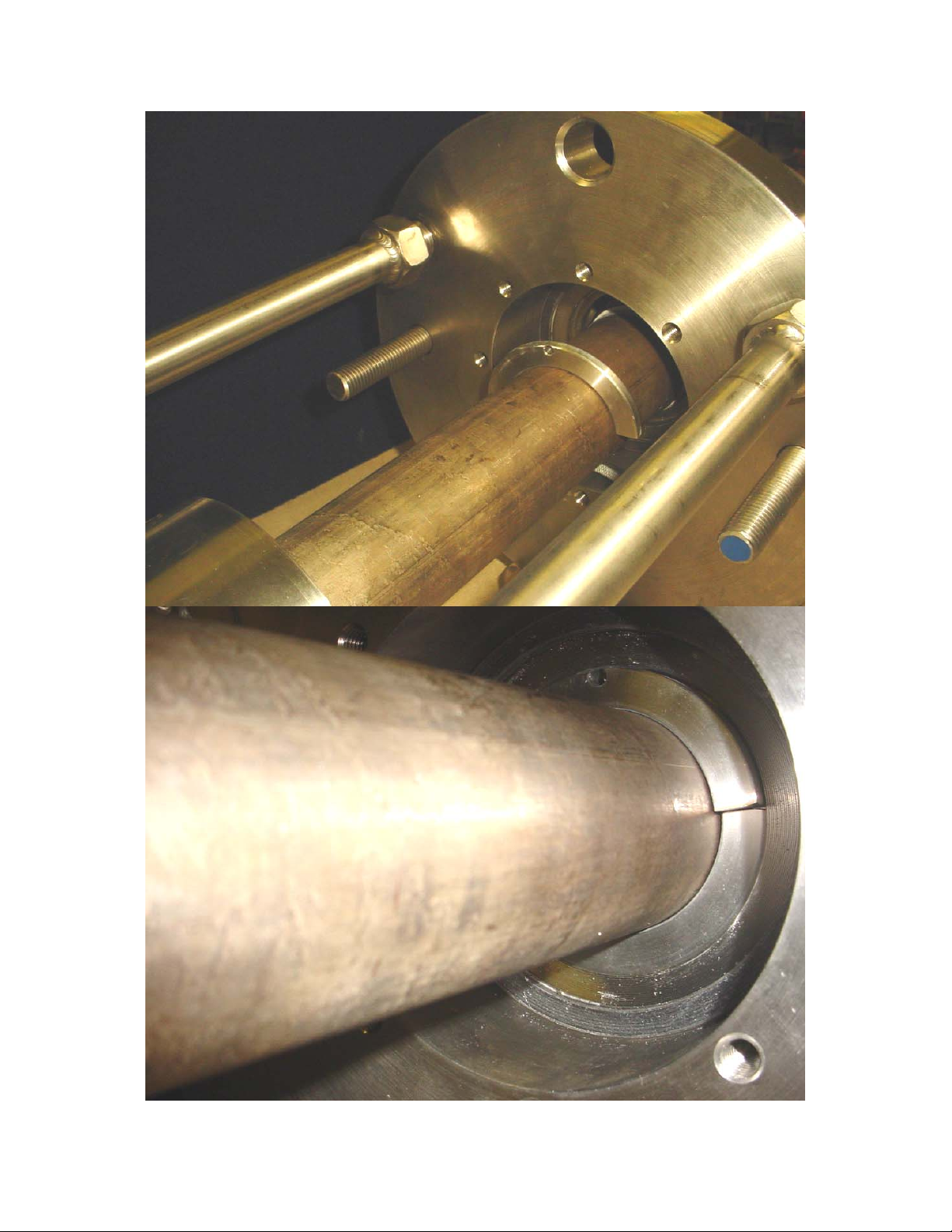
A split knurled ring is provided to scrape off cemented catalyst material that may
be deposited onto the probe body during subsequent removal. Insert the split
ring into the back of the packing box housing around the probe body. Ensure
that the small hole in the top half of the split ring fits over the pin in the back of
the weldment.
IB Addendum ISO1000
10
Page 11
IB Addendum ISO1000
11
Page 12

Slide the packing box assembly with 3 rope gaskets into the packing box
weldment.
IB Addendum ISO1000
12
Page 13

Bolt the 8-hole packing box retaining ring into place.
IB Addendum ISO1000
13
Page 14

Center the packing compression ring onto the packing material, and slide
the adjustment plate plate forward to the compression ring. Install two
adjustment nuts, and tighten slightly.
Adjust the packing adjustment nuts tight enough to minimize the escape
of pressurized process gas, but loose enough to let the probe slide back
and forth.
Install the two stop collars onto the two guide bars behind the carrier
assembly.
Open the gate valve fully.
Slide the probe all the way forward into the process, alternately locking
one stop collar or the other on the guide bars to prevent the probe from
sliding back under the process pressure. The probe may be rotated back
and forth as it is pushed in.
Once the probe is fully inserted, tighten the packing adjustment plate.
The packing is now the main process barrier, and no leakage should be
permitted.
IB Addendum ISO1000
14
Page 15

Entire guide bar/probe carrier assembly can now be removed if clearance is
desired around the installation.
IB Addendum ISO1000
15
Page 16

The entire valve/ packing box/ Probe assembly should be insulated to prevent
the condensation of process gases in the valve and also in the calibration gas
line inside the O
probe.
2
IB Addendum ISO1000
16
Page 17

IB Addendum ISO1000
17
Page 18

Probe removal is the reverse of the installation procedure:
1) If a pressure balancing system is being utilized, the inside (reference side) of
the probe must remain pressured up during the removal process.
2) Remove insulation from the entire assembly, exposing the packing box
assembly and probe.
Remove power from probe at an external breaker. If a World Class CENELEC
probe is used with rigid conduit, break the wire and conduit connections at the
separate close-coupled junction box. If an Oxymitter 4000/5000 is utilized,
wiring can be removed from the terminations side of the probe electronics
housing prior to retracting probe. Note:
electronics
isolated
side of the Oxymitter electronics housing until probe is
from the process and the balancing reference air is removed.
do not remove the end cap from the
IB Addendum ISO1000
18
Page 19

Re-install the probe guide rods and carrier plate. Probe flange must be
outboard of the carrier plate.
Attach retaining bar under the probe body.
IB Addendum ISO1000
19
Page 20

3) Loosen the two packing adjustment nuts enough to permit the probe to slide
out, but still maintain a minimum of process leakage.
4) Use the two safety stop collars on the guide bars, alternately locking them
into place to limit the distance the probe can slide if the process pressure
overcomes the packing friction.
IB Addendum ISO1000
20
Page 21
Rotate the probe back and forth to assist it’s withdrawal. Note that
catalyst cement may have accumulated onto the probe body (particularly
if the installation has not been well insulated), and repeated rotation back
and forth may be required to saw off this material.
IB Addendum ISO1000
21
Page 22

Installations that have been poorly insulated or heat traced well may have a
significant buildup of catalyst cement or other deposits due to condensation on the
probe body. A hydraulic cylinder can be utilized to assist in the withdrawal as
depicted below. Note that the cylinder pushes against the packing adjustment plate.
An extra nut is provided on the two threaded rods to prevent this pushing from overtightening the packing.
Cylinder kits are available from the factory – call 800-433-6076
IB Addendum ISO1000
22
Page 23

When the probe flange reaches the grooves in the guide rods, the probe is
beyond the gate, and the valve can be closed fully, isolating the process.
If the probe is not withdrawn completely, the gate of the valve will hit
the diffusion element, possibly causing breakage.
Carefully loosen the packing adjustment nuts further to ensure that the
gate valve has successfully isolated the process. Remove the nuts
completely, and slide the packing adjustment plate and the packing
adjustment ring back onto the probe body. Remove the 8 packing box
retaining bolts and the retainer plate, and string them back onto the probe
body. Continue withdrawing the probe.
IB Addendum ISO1000
23
Page 24

The large flame arrestor on the end of the probe will be close to the back
of the packing box. As the probe withdrawal continues, the flame
arrestor should push the entire packing box assembly back out of the
packing box weldment.
IB Addendum ISO1000
24
Page 25

String the packing box back onto the probe body. Recover the knurled
split ring, which should fall out behind the packing box. Inspect the
face gasket , and leave it in place if it appears to be in good condition.
5) Withdraw the probe until the end of the diffuser just rests inside the packing
box weldment.
6) Drop the retaining bar that holds the probe into the carrier assembly, and
completely remove the probe.
IB Addendum ISO1000
25
Page 26

Unscrew the large flame arrestor/diffuser from the end of the probe, and
slide the packing box off. The gasket material should be pushed out, and
should be inspected. Slide the packing adjusting ring, the 8-hole
packing box retaining ring, and the packing adjustment plate off of the
probe body.
Catalyst fines may have accumulated inside the packing box weldment.
Remove this by vacuuming, or blowing with an air hose.
IB Addendum ISO1000
26
Page 27

Pneumatic
Follow instructions in the instruction bulletin for the probe system. Applications
where process pressures are greater than a few PSI will require a pressure
balancing system, p/n 3D39811Gxx. This system operates by pressurizing the
inside of the O
probe with instrument reference air at the same pressure as the
2
process. The instrument air lines will have to remain connected as the probe is
inserted into and withdrawn from the process. This will require an extra length
of flexible reference air tubing. See IB 3D39811 for pressure balancing system.
Electrical Installation
Follow instructions in the instruction bulletin for the probe system. If a
CENELEC
World Class probe is being installed, utilize procedures to ensure
that an air-tight seal is made at the cable entry point. This will consist of a good
cable seal on the outside diameter of the cable, as well as potting or sealing
where the individual wires exit the overall cable sheath. This will prevent the
migration of high pressure balancing instrument air down the electrical cables.
The probe will be required to slide approximately 3 feet into and out of the
process. An extra length of power and signal cable may be provided to
accommodate this installation/removal procedure.
If rigid conduit is required, place an air-tight junction box close to the probe with
terminations inside. Prior to retraction, the terminations and conduit can be
removed at the junction box and the remaining length of cable/conduit and
junction box can ride with the probe as it retracts.
If an Oxymitter
probe is being installed, the electrical connections are isolated
from the pressure balancing instrument air by a cast bulkhead. The cover from
the terminations side (only) can be removed and electrical connections can be
removed at the probe prior to retraction while the inside of probe is still
IB Addendum ISO1000
27
Page 28

balanced. Do not attempt to remove the cover from the electronics side of the
probe until the pressure inside is at ambient as noted by the gauges provided.
Insulate the junction box (World Class) or electronics (Oxymitter) at the rear of
the probe to prevent condensation of process gases in the calibration gas line,
which runs the length of the probe. If an Oxymitter is used, monitor the
electronics temperature with a Model 275 HART communicator to ensure that
the temperature is not above 85°C (185°F)
IB Addendum ISO1000
28
Page 29

IB Addendum ISO1000
29
Page 30

Isolation Valving System Designations
OxyIso PR 2000 Material
1 316 Stainless Steel
2 Other
Valve
1 3” 300 # Gate Valve- 316 SS
2 Other
Probe
Probe Flange
Nozzle for Welding to Process
1 Rosemount General Purpose, 36”
2 Rosemount Hazardous Area, 36”
1 ANSI Gen Purpose 6.00” OD, 4.75 “ BC
2 DIN Gen Purpose 7.50” OD, 5.71” BC
3 JIS Gen.Purpose 6.50” OD, 5.12” BC
4 ANSI Haz. Area 7.75” OD, 6.00” BC
5 DIN Haz. Area 8.50” OD, 6.70” BC
6 Other
7 ANSI Haz. Area 3” 300 #
1 None- customer provided
2 3” 300# x 12” long 316 SS
3 Other
IB Addendum ISO1000
30
Page 31

Spare Parts
Item #6 Packing 1A99624H01
Item #4- Gasket 1A99624H02
Item #12 Gasket 1A99624H03
IB Addendum ISO1000
31
Loading...