


Model 951C NOx Analyzer
Instruction Manual
748214-W
August 2010
Applies to analyzers with SN# F-09000034 or higher.


TABLE OF CONTENTS
Section 1: Description and specifications
Typical applications . . . . . . . . . . . . . . . . . . . . . . . . . . . . . . . . . . . . . . . . . . . . . . . . . . . . . . . . . . . . . . . . . . . . . . . . . . 1-2
Specifications . . . . . . . . . . . . . . . . . . . . . . . . . . . . . . . . . . . . . . . . . . . . . . . . . . . . . . . . . . . . . . . . . . . . . . . . . . . . . . .1-3
Section 2: Installation
Unpacking . . . . . . . . . . . . . . . . . . . . . . . . . . . . . . . . . . . . . . . . . . . . . . . . . . . . . . . . . . . . . . . . . . . . . . . . . . . . . . . . . .2-1
Location . . . . . . . . . . . . . . . . . . . . . . . . . . . . . . . . . . . . . . . . . . . . . . . . . . . . . . . . . . . . . . . . . . . . . . . . . . . . . . . . . . . .2-1
Voltage requirements . . . . . . . . . . . . . . . . . . . . . . . . . . . . . . . . . . . . . . . . . . . . . . . . . . . . . . . . . . . . . . . . . . . . . . . .2-2
Operating on 230 VAC . . . . . . . . . . . . . . . . . . . . . . . . . . . . . . . . . . . . . . . . . . . . . . . . . . . . . . . . . . . . .2-3
Connecting cables . . . . . . . . . . . . . . . . . . . . . . . . . . . . . . . . . . . . . . . . . . . . . . . . . . . . . . . . . . . . . . . . . . . . . . . . . . .2-4
Connecting the power cord . . . . . . . . . . . . . . . . . . . . . . . . . . . . . . . . . . . . . . . . . . . . . . . . . . . . . . . . .2-5
Connecting the potentiometric recorder cables . . . . . . . . . . . . . . . . . . . . . . . . . . . . . . . . . . . . . . .2-6
Connecting the current recorder . . . . . . . . . . . . . . . . . . . . . . . . . . . . . . . . . . . . . . . . . . . . . . . . . . . .2-7
Adjusting the current output to produce a zero of 0 mA . . . . . . . . . . . . . . . . . . . . . . . . . . . . . . . .2-7
Gas requirements . . . . . . . . . . . . . . . . . . . . . . . . . . . . . . . . . . . . . . . . . . . . . . . . . . . . . . . . . . . . . . . . . . . . . . . . . . . .2-8
Air (U.S.P. Breathing Grade) . . . . . . . . . . . . . . . . . . . . . . . . . . . . . . . . . . . . . . . . . . . . . . . . . . . . . . . . .2-8
Span Gas . . . . . . . . . . . . . . . . . . . . . . . . . . . . . . . . . . . . . . . . . . . . . . . . . . . . . . . . . . . . . . . . . . . . . . . . .2-8
Sample requirements . . . . . . . . . . . . . . . . . . . . . . . . . . . . . . . . . . . . . . . . . . . . . . . . . . . . . . . . . . . . . .2-9
Connecting gas . . . . . . . . . . . . . . . . . . . . . . . . . . . . . . . . . . . . . . . . . . . . . . . . . . . . . . . . . . . . . . . . . . . .2-9
Leak testing . . . . . . . . . . . . . . . . . . . . . . . . . . . . . . . . . . . . . . . . . . . . . . . . . . . . . . . . . . . . . . . . . . . . . 2-10
Section 3: Operation
Front panel indicators and controls . . . . . . . . . . . . . . . . . . . . . . . . . . . . . . . . . . . . . . . . . . . . . . . . . . . . . . . . . . . .3-1
Display . . . . . . . . . . . . . . . . . . . . . . . . . . . . . . . . . . . . . . . . . . . . . . . . . . . . . . . . . . . . . . . . . . . . . . . . . . .3-1
Range selection . . . . . . . . . . . . . . . . . . . . . . . . . . . . . . . . . . . . . . . . . . . . . . . . . . . . . . . . . . . . . . . . . . .3-1
Blinking backlight . . . . . . . . . . . . . . . . . . . . . . . . . . . . . . . . . . . . . . . . . . . . . . . . . . . . . . . . . . . . . . . . . .3-2
Sample pressure gauge . . . . . . . . . . . . . . . . . . . . . . . . . . . . . . . . . . . . . . . . . . . . . . . . . . . . . . . . . . . . .3-3
Ozone pressure . . . . . . . . . . . . . . . . . . . . . . . . . . . . . . . . . . . . . . . . . . . . . . . . . . . . . . . . . . . . . . . . . . . .3-3
Zero and span potentiometers . . . . . . . . . . . . . . . . . . . . . . . . . . . . . . . . . . . . . . . . . . . . . . . . . . . . . .3-4
Ozone interlock . . . . . . . . . . . . . . . . . . . . . . . . . . . . . . . . . . . . . . . . . . . . . . . . . . . . . . . . . . . . . . . . . . .3-4
Starting the analyzer . . . . . . . . . . . . . . . . . . . . . . . . . . . . . . . . . . . . . . . . . . . . . . . . . . . . . . . . . . . . . . . . . . . . . . . . .3-6
Setting up remote range switching . . . . . . . . . . . . . . . . . . . . . . . . . . . . . . . . . . . . . . . . . . . . . . . . . . . . . . . . . . . . .3-9
Calibrating the analyzer . . . . . . . . . . . . . . . . . . . . . . . . . . . . . . . . . . . . . . . . . . . . . . . . . . . . . . . . . . . . . . . . . . . . 3-11
Zero calibrating . . . . . . . . . . . . . . . . . . . . . . . . . . . . . . . . . . . . . . . . . . . . . . . . . . . . . . . . . . . . . . . . . 3-11
Upscale calibrating . . . . . . . . . . . . . . . . . . . . . . . . . . . . . . . . . . . . . . . . . . . . . . . . . . . . . . . . . . . . . . . 3-12
Optimizing the converter temperature . . . . . . . . . . . . . . . . . . . . . . . . . . . . . . . . . . . . . . . . . . . . . . . . . . . . . . . 3-12
Measuring converter efficiency . . . . . . . . . . . . . . . . . . . . . . . . . . . . . . . . . . . . . . . . . . . . . . . . . . . . . . . . . . . . . . 3-14
Recommended calibration frequency . . . . . . . . . . . . . . . . . . . . . . . . . . . . . . . . . . . . . . . . . . . . . . . . . . . . . . . . 3-16
i

Section 4: Theory
Nitric oxide concentration is determination by chemilumineSEPTEMBER 2010scence method . . . . . . . .4-1
Analyzer flow system . . . . . . . . . . . . . . . . . . . . . . . . . . . . . . . . . . . . . . . . . . . . . . . . . . . . . . . . . . . . . . . . . . . . . . . . .4-1
Flow of sample, standard gas or zero gas to reaction chamber . . . . . . . . . . . . . . . . . . . . . . . . . . .4-4
Ozone generation . . . . . . . . . . . . . . . . . . . . . . . . . . . . . . . . . . . . . . . . . . . . . . . . . . . . . . . . . . . . . . . . .4-4
Signal conditioning and display . . . . . . . . . . . . . . . . . . . . . . . . . . . . . . . . . . . . . . . . . . . . . . . . . . . . . . . . . . . . . . . .4-5
Circuit functions . . . . . . . . . . . . . . . . . . . . . . . . . . . . . . . . . . . . . . . . . . . . . . . . . . . . . . . . . . . . . . . . . . .4-6
Analyzer thermal system . . . . . . . . . . . . . . . . . . . . . . . . . . . . . . . . . . . . . . . . . . . . . . . . . . . . . . . . . . . . . . . . . . . . . .4-9
Section 5: Routine servicing
System checks and adjustments . . . . . . . . . . . . . . . . . . . . . . . . . . . . . . . . . . . . . . . . . . . . . . . . . . . . . . . . . . . . . . .5-1
Adjusting the display fullscale span . . . . . . . . . . . . . . . . . . . . . . . . . . . . . . . . . . . . . . . . . . . . . . . . . .5-1
Factors affecting the overall sensitivity of the analyzer . . . . . . . . . . . . . . . . . . . . . . . . . . . . . . . . .5-2
Monitoring ozone output . . . . . . . . . . . . . . . . . . . . . . . . . . . . . . . . . . . . . . . . . . . . . . . . . . . . . . . . . . .5-2
Finding the cause of excessive background current . . . . . . . . . . . . . . . . . . . . . . . . . . . . . . . . . . . .5-3
Servicing the flow system . . . . . . . . . . . . . . . . . . . . . . . . . . . . . . . . . . . . . . . . . . . . . . . . . . . . . . . . . . . . . . . . . . . . .5-4
Cleaning the sample capillary . . . . . . . . . . . . . . . . . . . . . . . . . . . . . . . . . . . . . . . . . . . . . . . . . . . . . . .5-4
Confirming a faulty ozone restrictor fitting . . . . . . . . . . . . . . . . . . . . . . . . . . . . . . . . . . . . . . . . . . . . 5-6
Servicing the photomultiplier tube and the reaction chamber . . . . . . . . . . . . . . . . . . . . . . . . . . . . . . . . . . . . .5-8
Removing or replacing the photomultiplier assembly . . . . . . . . . . . . . . . . . . . . . . . . . . . . . . . . 5-10
Cleaning the reaction chamber . . . . . . . . . . . . . . . . . . . . . . . . . . . . . . . . . . . . . . . . . . . . . . . . . . . . 5-10
Reconstructing the photomultiplier assembly . . . . . . . . . . . . . . . . . . . . . . . . . . . . . . . . . . . . . . . 5-14
Photomultiplier tube and housing . . . . . . . . . . . . . . . . . . . . . . . . . . . . . . . . . . . . . . . . . . . . . . . . . 5-14
Replacing the photomultiplier tube . . . . . . . . . . . . . . . . . . . . . . . . . . . . . . . . . . . . . . . . . . . . . . . . 5-15
Ozone generater assembly . . . . . . . . . . . . . . . . . . . . . . . . . . . . . . . . . . . . . . . . . . . . . . . . . . . . . . . . . . . . . . . . . . 5-16
Removing the ultaviolet lamp and lamp housing . . . . . . . . . . . . . . . . . . . . . . . . . . . . . . . . . . . . 5-16
Replacing the ultaviolet lamp . . . . . . . . . . . . . . . . . . . . . . . . . . . . . . . . . . . . . . . . . . . . . . . . . . . . . 5-17
Removing the power supply . . . . . . . . . . . . . . . . . . . . . . . . . . . . . . . . . . . . . . . . . . . . . . . . . . . . . . 5-17
Converter assembly . . . . . . . . . . . . . . . . . . . . . . . . . . . . . . . . . . . . . . . . . . . . . . . . . . . . . . . . . . . . . . . . . . . . . . . . 5-18
Removing the glass converter tube . . . . . . . . . . . . . . . . . . . . . . . . . . . . . . . . . . . . . . . . . . . . . . . . 5-18
Servicing the electronic circuitry . . . . . . . . . . . . . . . . . . . . . . . . . . . . . . . . . . . . . . . . . . . . . . . . . . . . . . . . . . . . . 5-19
Section 6: Replacement parts
Matrix . . . . . . . . . . . . . . . . . . . . . . . . . . . . . . . . . . . . . . . . . . . . . . . . . . . . . . . . . . . . . . . . . . . . . . . . . . . . . . . . . . . . . . 6-1
Circuit board replacement policy . . . . . . . . . . . . . . . . . . . . . . . . . . . . . . . . . . . . . . . . . . . . . . . . . . . . . . . . . . . . . .6-2
Replacement parts . . . . . . . . . . . . . . . . . . . . . . . . . . . . . . . . . . . . . . . . . . . . . . . . . . . . . . . . . . . . . . . . . . . . . . . . . . .6-2
Common parts . . . . . . . . . . . . . . . . . . . . . . . . . . . . . . . . . . . . . . . . . . . . . . . . . . . . . . . . . . . . . . . . . . . .6-3
Photomultiplier assembly . . . . . . . . . . . . . . . . . . . . . . . . . . . . . . . . . . . . . . . . . . . . . . . . . . . . . . . . . . .6-5
Converter assembly 654070 . . . . . . . . . . . . . . . . . . . . . . . . . . . . . . . . . . . . . . . . . . . . . . . . . . . . . . . .6-7
Temperature control assembly 654068 . . . . . . . . . . . . . . . . . . . . . . . . . . . . . . . . . . . . . . . . . . . . . .6-8
ii

ESSENTIAL INSTRUCTIONS
READ THIS PAGE BEFORE PROCEEDING!
Rosemount Analytical designs, manufactures, and tests its products to meet many
national and international standards. Because these instruments are sophisticated
technical products, you MUST properly install, use, and maintain them to ensure
they continue to operate within their normal specifications. The following
instructions MUST be adhered to and integrated into your safety program when
installing, using, and maintaining Rosemount Analytical products. Failure to follow
the proper instructions may cause any one of the following situations to occur: Loss
of life; personal injury; property damage; damage to this instrument; and warranty
invalidation.
• Read all instructions prior to installing, operating, and servicing the product.
• If you do not understand any of the instructions, contact your Rosemount
Analytical representative for clarification.
• Follow all warnings, cautions, and instructions marked on and supplied with
the product.
• Inform and educate your personnel in the proper installation, operation, and
maintenance of the product.
• Install your equipment as specified in the Installation Instructions of the
appropriate Instruction Manual and per applicable local and national codes.
Connect all products to the proper electrical and pressure sources.
• To ensure proper performance, use qualified personnel
update, program, and maintain the product.
• When replacement parts are required, ensure that qualified people use
replacement parts specified by Rosemount. Unauthorized parts and
procedures can affect the product's performance, place the safe operation of
your process at risk, and VOID YOUR WARRANTY. Look-alike substitutions may
result in fire, electrical hazards, or improper operation.
• Ensure that all equipment doors are closed and protective covers are in place,
except when maintenance is being performed by qualified persons, to prevent
electrical shock and personal injury.
The information contained in this document is subject to change without notice.
to install, operate,

This page is intentionally left blank.

PREFACE
The purpose of this manual is to provide information concerning the components,
functions, installation and maintenance of the 951C NOx analyzer.
Some sections may describe equipment not used in your configuration. The user should
become thoroughly familiar with the operation of this module before operating it. Read
this instruction manual completely.
DEFINITIONS
The following definitions apply to dangers, warnings, cautions and notes found
throughout this publication.
DANGER
Highlights the presence of a hazard which will cause severe personal injury, death, or substantial property
damage if the warning is ignored.
WARNING
Highlights an operation or maintenance procedure, practice, condition, statement, etc. If not strictly
observed, could result in injury, death, or long-term health hazards of personnel.
CAUTION
Highlights an operation or maintenance procedure, practice, condition, statement, etc. If not strictly
observed, could result in damage to or destruction of equipment, or loss of effectiveness.
NOTE
Highlights an essential operating procedure, condition or statement.
vii

SAFETY SUMMARY
If this equipment is used in a manner not specified in these instructions, protective
systems may be impaired.
AUTHORIZED PERSONNEL
To avoid explosion, loss of life, personal injury and damage to this equipment and on site
property, all personnel authorized to install, operate and service the this equipment
should be thoroughly familiar with and strictly follow the instructions in this manual.
SAVE THESE IN-STRUCTIONS.
DANGER
ELECTRICAL SHOCK HAZARD
Do not operate without doors and covers secure. Servicing requires access to live parts which can cause
death or serious injury. Refer servicing to qualified personnel.
This instrument was shipped from factory set up to operate on 115 volt 50/60 Hz. For operation on 230
volt 50/60 Hz, refer to Section 2-3.
For safety and proper performance this instrument must be connected to a properly grounded threewire source of power.
WARNING
INTERNAL ULTRAVIOLET LIGHT HAZARD
Ultraviolet light from the ozone generator can cause permanent eye damage. Do not look directly at the
ultraviolet source in ozone generator. Use of ultraviolet filtering glasses is recommended.
viii

WARNING
TOXIC CHEMICAL HAZARD
This instrument generates ozone which is toxic by inhalation and is a strong irritant to throat and lungs.
Ozone is also a strong oxidizing agent. Its presence is detected by a characteristic pungent odor.
The instrument exhaust contains both ozone and nitrogen dioxide, both toxic by inhalation, and may
contain other constituents of the sample gas which may be toxic. Such gases include various oxides of
nitrogen, unburned hydrocarbons, carbon monoxide and other products of combustion reactions.
Carbon monoxide is highly toxic and can cause headache, nausea, loss of consciousness, and death.
Avoid inhalation of the ozone produced within the analyzer and avoid inhalation of the sample and
exhaust products transported within the analyzer. Avoid inhalation of the combined exhaust products
at the exhaust fitting.
Keep all tube fittings tight to avoid leaks. See Section 2-8 for Leak Test Procedure.
WARNING
PARTS INTEGRITY
Tampering or unauthorized substitution of components may adversely affect safety of this product. Use
only factory documented components for repair.
WARNING
HIGH PRESSURE GAS CYLINDERS
This instrument requires periodic calibration with a known standard gas. See Sections 2-5 and 3-3. See
also General Precautions for Handling and Storing High Pressure Gas Cylinders, page P-5.
ix

WARNING
TOXIC AND OXIDIZING GAS HAZ ARD
The ozone generator lamp contains mercury. Lamp breakage could result in mercury exposure.
Mercury is highly toxic if absorbed through skin or ingested, or if vapors are inhaled.
HANDLE LAMP ASSEMBLY WITH EXTREME CARE
If lamp is broken, avoid skin contact and inhalation in the area of the lamp or the mercury spill.
Immediately clean up and dispose of the mercury spill and lamp residue as follows:
• Wearing rubber gloves and goggles, collect all droplets of mercury by means of a suction pump and
aspirator bottle with long capillary tube. Alternatively, a commercially available mercury spill cleanup kit, such as J. T. Baker product No. 4439-01, is recommended.
• Carefully sweep any remaining mercury and lamp debris into a dust pan. Carefully transfer all
mercury, lamp residue and debris into a plastic bottle which can be tightly capped. Label and return
to hazardous material reclamation center.
• Do not place in trash, incinerate or flush down sewer.
• Cover any fine droplets of mercury in non-accessible crevices with calcium polysulfide and sulfur
dust.
WARNING
TOPPLING HAZARD
This instrument's internal pullout chassis is equipped with a safety stop latch located on the left side of
the chassis.
When extracting the chassis, verify that the safety latch is in its proper (counter-clockwise) orientation.
If access to the rear of the chassis is required, the safety stop may be overridden by lifting the latch;
however, further extraction must be done very carefully to insure the chassis does not fall out of its
enclosure.
If the instrument is located on top of a table or bench near the edge, and the chassis is extracted, it
must be supported to prevent toppling.
Failure to observe these precautions could result in personal injury and/or damage to the product.
x

GENERAL PRECAUTIONS FOR HANDLING AND
STORING HIGH PRESSURE GAS CYLINDERS
1. Never drop cylinders or permit them to strike each other violently.
2. Cylinders may be stored in the open, but in such cases, should be protected against
extremes of weather and, to prevent rusting, from the dampness of the ground.
Cylinders should be stored in the shade when lo-cated in areas where extreme
temperatures are prevalent.
3. The valve protection cap should be left on each cylinder until it has been secured
against a wall or bench, or placed in a cylinder stand, and is ready to be used.
4. Avoid dragging, rolling, or sliding cylinders, even for a short distance; they should
be moved by using a suit-able hand-truck.
5. Never tamper with safety devices in valves or cylinders.
6. Do not store full and empty cylinders together. Serious suckback can occur when an
empty cylinder is at-tached to a pressurized system.
7. No part of cylinder should be subjected to a temperature higher than 125° F (52° C).
A flame should never be permitted to come in contact with any part of a
compressed gas cylinder.
1
8. Do not place cylinders where they may become part of an electric circuit. When
electric arc welding, precau-tions must be taken to prevent striking an arc against
the cylinder.
1. Compressed Gas Association, Handbook of Compressed Gases, Second Edition, Van Nostrand Reinhold
Company, 135 West 50th Street, New York, NY 10020, © 1981.
xi

CONDENSED STARTUP AND CALIBRATION
PROCEDURE
The following summarized instructions on startup and calibration are intended for
operators already familiar with the analyzer.
For initial startup, refer to detailed instructions provided in “Operation” on page 3-1.
1. Review the Purchase Order and make a note of the range that was purchased–Low
Range, Mid Range, or High Range.
2. Set the Range switch on the Signal Conditioning board to position 4, 250ppm,
500ppm, or 2500 ppm.
3. On the Signal Conditioning board, verify that the correct Hi/Mid/Lo Selection
Jumpers are installed for the range that was purchased.
4. Turn on the analyzer. It will take approximately one to two hours to reach
temperature equilibrium, which is required for calibration.
5. Verify that the air cylinder’s pressure regulator is set to a pressure of 20 to 25 psig.
6. Establish the correct sample gas pressure:
a. Supply sample gas to rear-panel sample inlet at 15 psig.
b. Adjust the sample back pressure regulator so that the sample pressure gauge
indicates 4 psig.
7. Establish the correct zero gas pressure :
a. Supply zero gas to the rear panel sample inlet and set to 15 psig.
b. Note the reading on the sample pressure gauge. It should be the same as in
Step 7b. If not, adjust the output pressure regulator on the zero gas cylinder
as required.
xii

8. Establish the correct upscale standard gas pressure:
a. Supply upscale standard gas to the rear panel sample inlet.
b. Note the reading on the sample pressure gauge. It should be the same as in
Step 7b. If not, adjust the output regulator as required.
NOTE
Supply pressure for sample, upscale standard gas and zero air must be the same. If not, the readout will
be inaccurate.
9. Do the following to perform a zero calibration:
a. Set the PPM RANGE Switch to the range to be used for sample analysis.
b. Set the front panel Range 1 potentiometer to its normal operating setting, if
known; otherwise, set the potentiometer to the middle setting–that is,
halfway between the left and the right settings.
c. Supply zero gas to the rear panel sample inlet.
d. Adjust the front panel Zero potentiometer to achieve a reading of zero on a
multimeter or recorder.
10. Do the following to perform an upscale calibration:
a. Set PPM RANGE Switch at setting appropriate to the particular span gas.
b. Supply upscale standard gas to the rear panel sample inlet.
c. Adjust front panel the Range 1 potentiometer so that a reading on a
multimeter or recorder is equal to the upscale standard gas’ known NOX
concentration.
d. Adjust R25 on the signal board so that the display value and the recorder
output are equal.
NOTE
It is the responsibility of the user to measure the efficiency of the NO2-to-NO converter during the initial
startup, and at intervals thereafter appropriate to the application–normally once a month.
xiii

This page is intentionally left blank.
xiv

Section 1: Description and specifications
The Model 951C NOx analyzer continuously analyzes a flowing gas sample for nitric oxide
(NO) and nitrogen dioxide (NO2). The sum of the two concentrations is reported as NOx.
The analyzer is designed to measure NOx using one of three sets of ranges designated as
Hi, Mid, or Lo.
The analysis is based on the chemiluminescence method of NO detection. The sample is
continuously passed through a heated bed of vitreous carbon, in which NO
NO. Any NO initially present in the sample passes through the converter unchanged, and
any NO
amount of NO.
The NO is quantitatively converted to NO2 by gas phase oxidation with molecular ozone
produced within the analyzer from air supplied by an external cylinder. During this
reaction, approximately 10% of the NO2 molecules are elevated to an electronically
excited state, followed by immediate decay to the non excited state, accompanied by
the emission of photons. These photons are detected by a photomultiplier tube, which in
turn generates a DC current proportional to the concentration of NOx in the sample
stream. The current is then amplified and used to drive a front panel display and to
provide potentiometric and isolated current outputs.
initially present in the sample is converted to an approximately equivalent (95%)
2
is reduced to
2
To minimize system response time, an internal sample bypass feature provides high
velocity sample flow through the analyzer.
The case heater assembly of the Model 951C maintains the internal temperature at
approximately 50° C (122° F).
1-1

Instruc tion Manual Rosemo unt Analyt ical
748214-W SEPTEMBER 2010
1.1 Typical applications
The Model 951C analyzer has the following specific applications:
• Oxides of nitrogen (NOx) emissions from the combustion of fossil fuels in:
- Vehicle engine exhaust
- Incinerators
- Boilers
- Gas appliances
- Turbine exhaust
• Nitric acid plant emissions
• Ammonia in pollution control equipment (with converter)
• Nitric oxide emissions from decaying organic material (i.e., landfills).
1-2

Ro semoun t Analyti cal Ins tru ction M anual
SEPTEMBER 2010 748214-W
1.2 Specifications
Repeatability Within 0.1 ppm or ±1% of fullscale, whichever is greater
Zero/Span Drift Less than ±0.1 ppm or ±1% of fullscale, whichever is greater, in 24 hours at
constant temperature
Less than ±0.2 ppm or ±2% of fullscale, whichever is greater, over any 10 C
interval from 4 to 40 C (for rate change of 10 C or less per hour)
Response Time
(Electronic + Flow)
Sensitivity Less than 0.1 ppm or 1% of fullscale, whichever is greater
Detector Operating
Pressure
Total Sample Flow Rate 1 Liter per minute at 20 psig
Sample Pressure 138 kPa (20 psig)
Ozone Generator Gas U.S.P. breathing-grade air
Ambient Temperature
Range
Analog Output
Potentiometric 0 to +5 VDC, 2000 ohm minimum load
Isolated Current Field-selectable 0 to 20 or 4 to 20 mA, 700 ohm max load
Display Digital, 4-1/2 digit LCD, readout in engineering units, back-lighted
Power Requirements 115/230 VAC 10%, 50/60 3 Hz, 570 W maximum
Enclosure General purpose for installation in weather-protected areas
Dimensions 8.7 in. x 19.0 x 19.0 in. (H x W x D)
Weight 22.2 kg (49 lbs) approximate
90% of fullscale in less than 1 minute
Atmospheric
4 to 40 C (40 to 104 F)
22.0 cm x 48.3 cm x 48.3 cm (H x W x D)
1-3

Instruc tion Manual Rosemo unt Analyt ical
748214-W SEPTEMBER 2010
This page is intentionally left blank.
1-4
Section 2: Installation
2.1 Unpacking
Carefully examine the shipping carton and contents for signs of damage. Immediately
notify the shipping carrier if the carton or its contents are damaged. Retain the carton
and packing material until the instrument is operational.
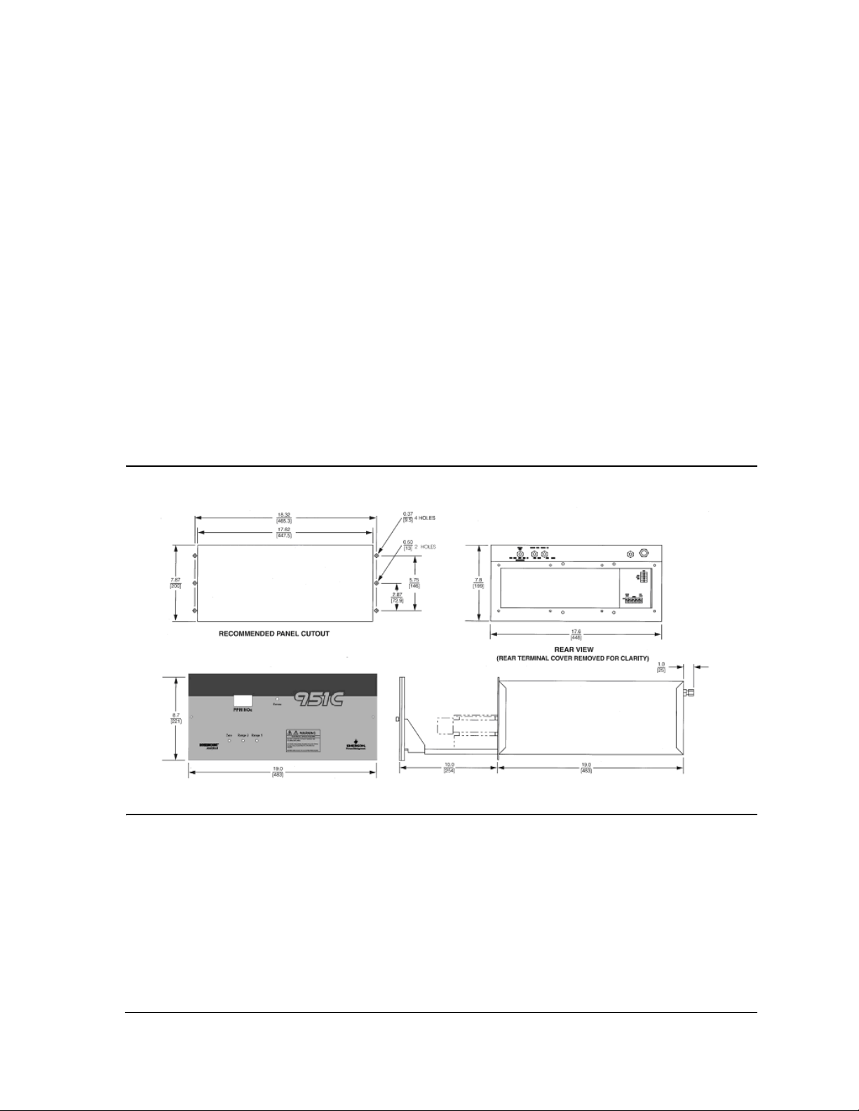
2.2 Location
Install analyzer in a clean area, free from moisture and excessive vibration, at a stable
temperature within 4 to 40° C.
Figure 2-1: Panel Cutout / Installation Drawing
The analyzer should be mounted near the sample source to minimize sample transport
time.
2-1

Instruc tion Manual Rosemo unt Analyt ical
748214-W SEPTEMBER 2010
A temperature control system maintains the internal analyzer temperature at 50° C (122°
F) to ensure proper operation over an ambient temperature range of 4 to 40° C (40 to
104° F). Temperatures outside these limits necessitate the use of special temperature
controlling equipment or environmental protection. Also, the ambient temperature
should not change at a rate exceeding 10° C per hour.
The cylinders of air and span gas should be located in an area of constant ambient
temperature.
2.3 Voltage requirements
WARNING
ELECTRICAL SHOCK HAZARD
For safety and proper performance this instrument must be connected to a properly grounded three-
wire source of power.
This instrument was shipped from the factory pre-configured to operate on 115 VAC, 50/
60 Hz electric power.
2-2
Ro semoun t Analyti cal Ins tru ction M anual
SEPTEMBER 2010 748214-W
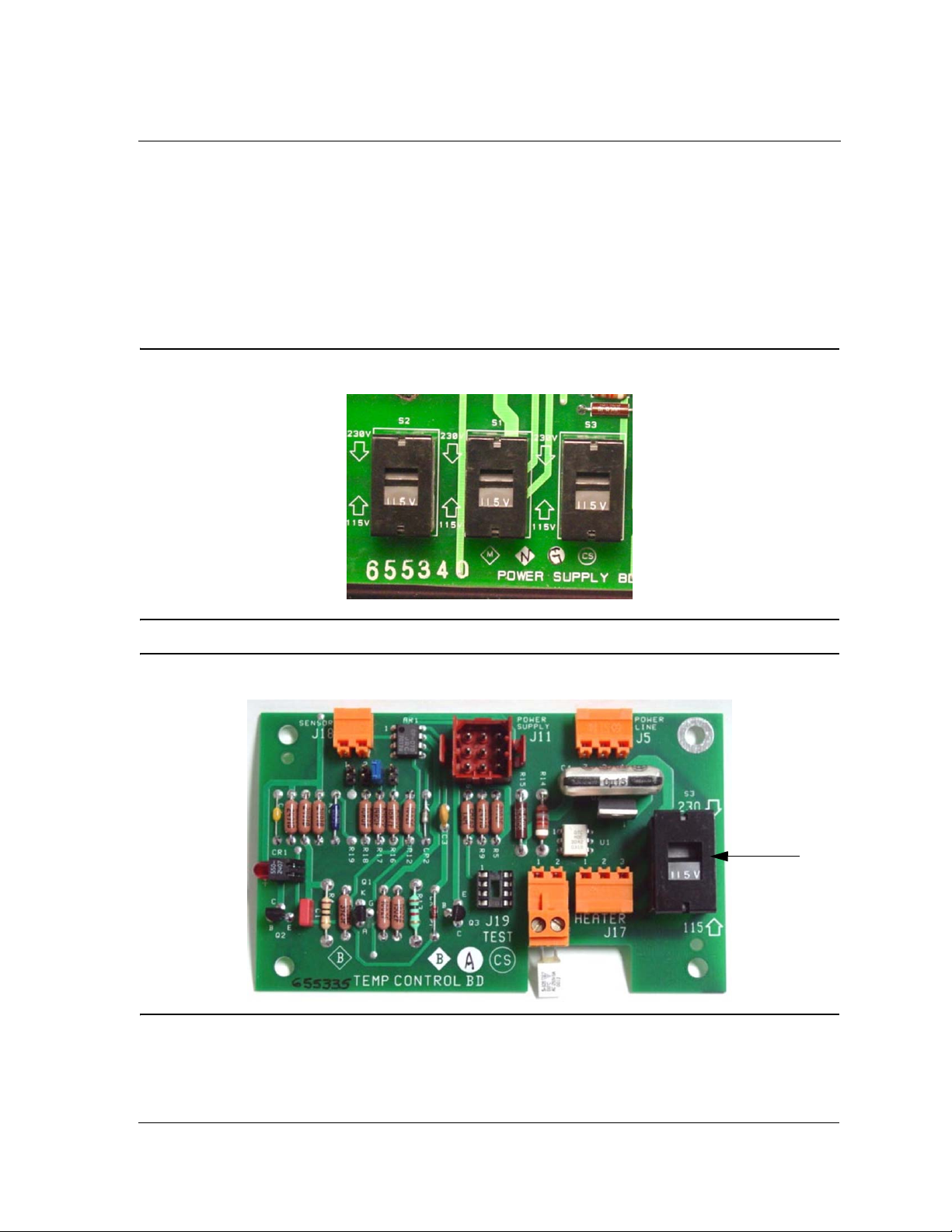
2.3.1 Operating on 230 VAC
To operate the analyzer on 230 VAC, 50/60 Hz, do the following:
1. Set the voltage select switches (S1, S2, S3) on the Power Supply Board and the
voltage select switch (S3) on the Temperature Control Board to the 230 VAC
position.
Figure 2-2: Power Supply Board voltage select switches
Figure 2-3: Temperature Control board voltage select switch
S3
2-3

Instruc tion Manual Rosemo unt Analyt ical
748214-W SEPTEMBER 2010
2. On the rear of the analyzer, replace the 6.25 A fuse with the 3.15 A fuse (P/N
898587) that is provided in the shipping kit.
Figure 2-4: Rear view of Model 951C (cover removed)
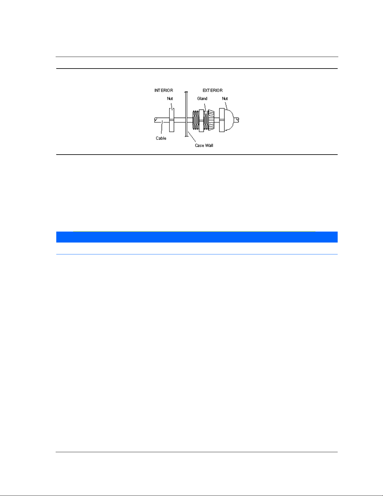
2.4 Connecting cables
The power (PN# 899330) and recorder (PN# 899329) cable glands are supplied in the
shipping kit. To connect the appropriate cable to its connector or terminal strip on the
analyzer, do the following:
1. Remove the analyzer’s rear cover to access the terminals.
2. Route each cable through its cable gland and connect to the appropriate connector
or terminal strip.
2-4
Ro semoun t Analyti cal Ins tru ction M anual
SEPTEMBER 2010 748214-W
Figure 2-5: Cable gland
3. Tighten the glands.
2.4.1 Connecting the power cord
If this instrument is located on a bench or table top or is installed in a protected rack,
panel or cabinet, power can be connected with a 3-wire flexible power cord.
NOTE
The power cord must be atleast 18 AWG with a maximum outside diameter (OD) of .48 inches.
To connect the power cord to the Model 951C, do the following:
1. Using the cable gland (PN# 899330) that is provided in the installation kit, insert
the power cord through the hole on the Model 951C that is labeled POWER.
2. Connect the power cord leads to TB1 on the rear panel.
3. Tighten the cable gland adequately to prevent the rotation or slippage of the power
cable. Since the rear terminals do not slide out with the chassis, no excess power
cable slack is necessary.
2-5

Instruc tion Manual Rosemo unt Analyt ical
748214-W SEPTEMBER 2010
The following power cord and/or support feet are available:
• Power cord (PN# 634061), which contains a 10-foot North American power cord
set.
• Enclosure Support Kit (PN# 634958), which contains four enclosure support feet for
bench top use.
• Power Cord/Enclosure Support Kit (PN# 654008), which contains a 10-foot North
American power cord set and four enclosure support feet.
NOTE
If the instrument is permanently mounted in an open panel or rack, use electrical metal tubing or conduit.
2.4.2 Connecting the potentiometric recorder cables
Potentiometric recorder cables connect to the rear panel. Route the cable through the
cable gland in the hole on the Model 951C that is labeled RECORDER OUTPUT and
connect the cable’s leads tothe VOLT OUTPUT terminals.
Table 2-1. Potentiometric cable specifications
Distance from recorder to analyzer: 1000 feet (305 meters) maximum
Input impedance: Greater than 2000 ohms
Cable (user supplied): Two conductor, shielded, min. 20 AWG
Voltage output: 0 to +5 VDC
2-6

Ro semoun t Analyti cal Ins tru ction M anual
SEPTEMBER 2010 748214-W
2.4.3 Connecting the current recorder
Current recorder cables connect to the rear panel. Route the cable through the cable
gland in the hole on the Model 951C that is labeled RECORDER OUTPUT and connect the
cable’s leads to the CUR OUTPUT terminals.
Table 2-2. Recorder cable specifications
Distance from recorder to analyzer: 3000 feet (915 meters).maximum
Load resistance: Less than 700 Ohms
Cable (user supplied): Two conductor, shielded, min. 20 AWG
Voltage output: 0 to +5 VDC
2.4.4 Adjusting the current output to produce a zero of 0 mA
Do the following to adjust the current output to produce a zero of 0 mA:
1. Do the following to establish the correct zero gas pressure:
a. Supply zero gas to rear panel sample inlet.
b. Note the reading on internal sample pressure gauge. It should be the same as
the nominal 4 psig (28 kPa) sample pressure indicated on the internal sample
pressure gauge.
c. The internal sample pressure should remain constant when the analyzer input
sample is switched from a calibration gas standard to a zero gas standard. This
can be assured by setting the delivery pressure from the sample gas cylinder
and the zero gas cylinder equal to the delivery pressure of the span gas
cylinder, which is 20 psig (138 kPa). If this cannot be accomplished, adjust the
output pressure regulator on the zero gas cylinder as required.
2. Adjust R23, the zero adjust potentiometer on the power supply board, to produce 0
mA current output.
2-7

Instruc tion Manual Rosemo unt Analyt ical
748214-W SEPTEMBER 2010
2.5 Gas requirements
The instrument requires two gases normally supplied from cylinders: air and span gas.
2.5.1 Air (U.S.P. Breathing Grade)
Air is used as both an oxygen source for the generation of the ozone required for the
chemiluminescence reaction, and as a standard gas for zero calibration. Air for each
purpose must be supplied from a separate cylinder due to the different pressure
requirements at the ozonator and the zero inlets.
2.5.2 Span Gas
Span gas is a standard gas of accurately known composition that is used to set an upscale
calibration point. The usual span gas is NO or NO2 in a background of nitrogen.
WARNING
HIGH PRESSURE GAS CYLINDERS
The Model 951C requires periodic calibration with a span gas. “Calibrating the analyzer” on page 3-10.
See also General Precautions for Handling and Storing High Pressure Gas Cylinders, page P-5.
NOTE
For maximum calibration accuracy, the concentration of nitrogen oxide in the span gas should be similar to
that in the sample gas. Also, the span gas should be supplied to the Model 951C’s rear panel sample inlet
at the same pressure as the sample gas. To ensure constant pressure, use a pressure regulator immediately
upstream from the sample inlet.
Each span gas used should be supplied from a tank or cylinder equipped with a clean,
noncorrosive, two-stage regulator. In addition, a shut off valve is recommended.
Install the gas cylinders in an area of relatively constant ambient temperature.
2-8

Ro semoun t Analyti cal Ins tru ction M anual
SEPTEMBER 2010 748214-W
2.5.3 Sample requirements
The sample gas must be clean and dry before entering the analyzer. In general, the
sample should be filtered to eliminate particles larger than two microns and should have
a dew point below 90° F (32° C).
NOTE
Proper supply pressure for sample, zero and span gases for the Model 951C is 20 psig (138 kPa).
2.5.4 Connecting gas
WARNING
TOXIC AND OXIDIZING GAS HAZ ARDS
This instrument generates ozone which is toxic by inhalation and is a strong irritant to throat and lungs.
Ozone is also a strong oxidizing agent. Its presence is detected by a characteristic pungent odor.
The instrument exhaust contains both ozone and nitrogen dioxide, both toxic by inhalation, and may
contain other constituents of the sample gas which may be toxic. Such gases include various oxides of
nitrogen, unburned hydrocarbons, carbon monoxide and other products of combustion reactions.
Carbon monoxide is highly toxic and can cause headache, nausea, loss of consciousness, and death.
Avoid inhalation of the ozone produced within the analyzer and avoid inhalation of the sample and
exhaust products transported within the analyzer. Avoid inhalation of the combined exhaust products
at the exhaust fitting.
Keep all tube fittings tight to avoid leaks. See Section 2-8 for Leak Test Procedure.
Connec t rear exhaust outlet to outside vent by a 1/4 inch (6.3 mm) or larger stainless steel or Teflon line.
To connect a gas to the Model 951C, do the following:
1. Remove plugs and caps from all inlet and outlet fittings.
2. Connect the exhaust outlet to the external vent with stainless steel or teflon tubing
that has an outside diameter of atleast .25 inches (6.3 mm).
3. Connect the external lines from the ozonator air and sample sources to the
corresponding rear panel inlet ports. For sample line, stainless steel tubing is
recommended.
4. Adjust the regulator on the ozonator air cylinder to an output pressure of 20 to 25
psig (138 to 172 kPa). At least 20 psig should be present at the rear of the analyzer.
5. Supply sample gas to the rear panel sample inlet at appropriate pressure: 20 psig
(138 kPa).
2-9

Instruc tion Manual Rosemo unt Analyt ical
748214-W SEPTEMBER 2010
2.5.5 Leak testing
The following test is designed for sample pressure up to 10 psig (35 kPa).
1. Supply air or an inert gas such as nitrogen to the analyzer’s sample and air input
fittings at 10 psig (35 kPa).
2. Use a tube cap to seal off the analyzer’s exhaust fitting.
3. Cover all fittings, seals, and other possible leak sources with a liquid leak detector
such as Snoop® (PN# 837801).
4. Check for bubbling or foaming, which indicates leakage, and repair as required.
Any leakage must be corrected before introduction of sample and/or application of
electrical power.
To further confirm that the system is free of leaks, perform one of the tests in Section 5.
2-10

Section 3: Operation
To analyze a sample stream, do the following:
1. Calibrate the analyzer. See “Calibrating the analyzer” on page 3-11 for more
information.
2. Supply sample gas to the sample inlet.
3. Set the PPM RANGE Switch to the appropriate position.
The Model 951C will begin analyzing the sample stream and is designed for continuous
operation. Normally, it is never turned off except for servicing or for a prolonged shutdown.
NOTE
During periods of shutdown, turn off the ozone lamp by shutting off the input air source.
3.1 Front panel indicators and controls
3.1.1 Display
The display is a 4-digit liquid crystal device that always displays NOX concentration in
parts per million.
3.1.2 Range selection
The Model 951C can be configured to perform its analysis within one of three sets of
ranges designated as Hi, Mid, or Lo.
NOTE
The Model 951C’s range is not user-selectable–it is configured at the factory based on the purchase
order. Any desired changes to the analyzer’s range must be handled at the factory.
3-1

Instruc tion Manual Rosemo unt Analyt ical
748214-W SEPTEMBER 2010
The Hi range set consists of spans with the following ranges:
• 0-100 ppm NO
• 0-250 ppm NO
• 0-1000 ppm NO
• 0-2500 ppm NO
X
X
X
X
The Mid range set consists of spans with the following ranges:
• 0-20 ppm NO
• 0-50 ppm NO
• 0-200 ppm NO
• 0-500 ppm NO
X
X
X
X
The Lo range set consists of spans with the following ranges:
• 0-10 ppm NO
• 0-25 ppm NO
X
X
• 0-100 ppm NO
• 0-250 ppm NO
X
X
The span range is selected by setting the PPM RANGE Switch and the five configuration
jumpers on the signal board to the desired range sensitivity for the recorder output.
3.1.3 Blinking backlight
The backlight blinks when the analyzer’s sensitivity is 10% or more over the range
setting.
To restore function, set the PPM RANGE Switch to a less sensitive (higher) range by
moving it one step to the right.
3-2

Ro semoun t Analyti cal Ins tru ction M anual
SEPTEMBER 2010 748214-W
3.1.4 Sample pressure gauge
The internal sample pressure (nominally 4 psig or 28 kPa) is adjusted by rotation of the
sample pressure regulator.
NOTE
Using the MID ranges (20, 50, 200, and 500 ppm NOx), set the sample pressure regulator to 4.0 psig (28
kPa).
3.1.5 Ozone pressure
The ozone pressure is determined by the pressure regulator of the air supply cylinder. A
nominal pressure of 20 to 25 psig (138 to 172 kPa) is recommended. Proper operation is
indicated when the front panel ozone indicator lamp is lit.
NOTE
If ozone lamp does not light, increase pressure slightly by adjusting pressure regulator control on the air
cylinder.
3-3

Instruc tion Manual Rosemo unt Analyt ical
748214-W SEPTEMBER 2010
Figure 3-1: Model 951C Controls, Indicators and Adjustments
3.1.6 Zero and span potentiometers
You can adjust the Zero, Range1 and Range2 potentiometers on the signal board by way
of screwdriver access holes on the front panel .
3.1.7 Ozone interlock
The ozone-producing UV lamp will not ignite or stay lit unless adequate air pressure is
present at the air inlet. Nominal setpoint pressure is 20 to 25 psig (138 to 172 kPa).
3-4

Ro semoun t Analyti cal Ins tru ction M anual
SEPTEMBER 2010 748214-W
Figure 3-2: Signal board
Figure 3-3: Signal board test points
3-5

Instruc tion Manual Rosemo unt Analyt ical
748214-W SEPTEMBER 2010
3.2 Starting the analyzer
To start up the Model 951C, do the following:
1. Supply electrical power to the analyzer. The will take the analyzer approximately
two hours to reach temperature equilibrium, which is necessary to calibrate the
analyzer.
2. Make the following adjustments to the signal board:
a. Using a small flat screwdriver, set the PPM RANGE Switch to the range that will
be used for sample analysis.
Figure 3-4: PPM Range Select Switch
Range
(S1 Pos)
11020 100
22550 250
3 100 200 1000
4 250 500 2500
Other Remote Remote Remote
ppm Fullscale
Lo Range Mid Range Hi Range
b. Set the configuration jumper settings to your desired position based on the
information provided in Figure 3-5.
3-6

Ro semoun t Analyti cal Ins tru ction M anual
SEPTEMBER 2010 748214-W
Figure 3-5: Configuration Jumper Settings
c. Set the Range2 selection jumpers to Range 4, 2500ppm as shown in Figure 3-
6.
Figure 3-6: Range 2 Selection Jumpers
Range Position
JP1 10 20 100
JP2 25 50 250
JP3 100 200 1000
JP4 250 500 2500
PPM Range
Lo Mid Hi
3-7

Instruc tion Manual Rosemo unt Analyt ical
748214-W SEPTEMBER 2010
3. Adjust the ozone pressure regulator so that the ozone pressure gauge rests at 20 to
25 psig (138 to 172 kPa).
4. Do the following to establish the correct zero gas pressure:
a. Supply zero gas to rear panel sample inlet.
b. Note the reading on internal sample pressure gauge. It should be the same as
the nominal 4 psig (28 kPa) sample pressure indicated on the internal sample
pressure gauge.
c. The internal sample pressure should remain constant when the analyzer input
sample is switched from a calibration gas standard to a zero gas standard. This
can be assured by setting the delivery pressure from the sample gas and the
zero gas cylinder equal to the delivery pressure of the span gas cylinder, which
is 20 psig (138 kPa). If this cannot be accomplished, adjust the output
pressure regulator on the zero gas cylinder as required.
5. Do the following to establish the correct sample gas pressure:
a. Supply sample gas to the rear panel sample inlet.
b. Adjust the sample backpressure regulator so that the internal sample pressure
gauge indicates the value appropriate to the desired operating range.
NOTE
The inability to obtain a flow of one liter per minute at the exhaust outlet usually indicates insufficient
sample supply pressure at the sample inlet. Use a 2400 cc flowmeter (i.e., Brooks PN# 1350) at the exhaust
6. Do the following to establish the correct flow of upscale standard gas:
a. Supply upscale standard gas to the rear panel sample inlet.
b. Adjust the sample backpressure regulator so that the internal sample pressure
gauge indicates the value appropriate to the desired operating range.
NOTE
Supply pressures for sample and upscale standard gases must be the same. Otherwise, readout will be
inaccurate.
The analyzer is now ready for calibration.
3-8

Ro semoun t Analyti cal Ins tru ction M anual
SEPTEMBER 2010 748214-W
Figure 3-7: Power Supply Board
3.3 Setting up remote range switching
The Model 951C can be configured to switch ranges, via a control system such as a PLC or
DCS, when a pre-defined NOx measurement setpoint is reached.
You will need the following to configure the Model 951C for remote range switching:
• A control system–typically a PLC or DCS.
• A single pole double throw (SPDT) switch that is controlled by the control system.
3-9

Instruc tion Manual Rosemo unt Analyt ical
748214-W SEPTEMBER 2010
To configure the Model 951C for remote range switching, do the following:
1. Review the following table, which lists the range spans for each type of Model 951C
analyzer, to find the setpoint range that should trigger the remote range switching
feature.
Remote Range
Connector (J2)
Range 1 10 20 100
Range 2 25 50 250
Range 3 100 200 1000
Range 4 250 500 2500
Lo Mid Hi
2. Connect the SPDT to the appropriate range node–typically Range 3 or Range 4–on
the terminal strip (J2) located on the back end of the analyzer.
Figure 3-8: Model 951C rear panel showing J2
3-10

Ro semoun t Analyti cal Ins tru ction M anual
SEPTEMBER 2010 748214-W
3. Install a jumper on the corresponding Range2 Selection jumper on the Signal
board. For example, if you connect the SPDT to Range 3 at J2, then you would
install a jumper at JP3 of Range2 Selection.
Figure 3-9: Range2 Selection Jumpers
4. Set up your control system so that the SPDT switches when the Model 951C’s
analog output reaches or exceeds the desired switch point that you selected in Step
1.
3.4 Calibrating the analyzer
There are two kinds of calibration: zero calibration and upscale calibration.
3.4.1 Zero calibrating
An effective zero calibration requires that the analyzer be exposed to clean air.
To perform a zero calibration, do the following:
1. On the signal board, set PPM RANGE Switch to the same range that will be used
during the sample analysis.
2. Set the front panel RANGE1 potentiometer to mid-range--that is, do not set it all
the way to the left, nor all the way to the right.
3. Supply zero gas to the rear panel sample inlet and wait approximately two minutes.
4. Set the sample pressure to 4.0 psig (27.6 kPa).
5. After a stable reading is reached, turning the ZERO potentiometer on the front
panel of the analyzer until a zero reading is obtained.
3-11

Instruc tion Manual Rosemo unt Analyt ical
748214-W SEPTEMBER 2010
3.4.2 Upscale calibrating
1. On the signal board, set the Upscale Calibration PPM RANGE Switch to the position
appropriate to the particular span gas.
2. Supply upscale standard gas to the rear panel sample inlet.
3. Set the sample pressure to 4.0 psig (27.6 kPa).
4. Using a screwdriver, turn the front panel RANGE1 potentiometer so that the reading
on the display or recorder is equal to the known concentration of NOX in the span
gas. If the correct reading is unattainable using this method, go to Step 5.
5. Adjust the R30 potentiometer on the power supply board clockwise to raise the
photomultiplier voltage and increase the sensitivity of the analyzer. Repeat the zero
calibration and upscale calibration procedures.
6. If necessary, do the following:
a. Increase the upscale readings on the LCD display by ad-justing the R43
potentiometer until the display shows the correct span gas readings.
b. Adjust the R25 potentiometer so that the reading on the display and the
recorder is equal to the known concentration of NOX in the span gas.
3.5 Optimizing the converter temperature
The converter temperature can be adjusted once the appropriate high voltage and
electronic gain have been selected and the value displayed by the Model 951C matches
the calibration gas value.
The vitreous carbon converter used in this analyzer has a low surface area that gradually
increases during high temperature operation of the converter material.
Initially, the temperature of the peak of the converter efficiency starts at a relatively high
value because significant heat must be supplied to make the converter active enough to
reduce the input nitrogen dioxide to nitric oxide at the required 95% level. During the
operation of the analyzer, the temperature of the peak will fall as the surface area of the
converter is increased and less external energy is required to cause adequate conversion.
3-12

Ro semoun t Analyti cal Ins tru ction M anual
SEPTEMBER 2010 748214-W
In extreme cases, where converter re-profiling has not been conducted, the converter is
so active that it not only reduces nitrogen dioxide to nitric oxide, but it also reduces the
nitric oxide to nitrogen, which is not detected by the chemiluminescence reaction. The
remedy in this case is to lower the converter temperature, thereby improving the
converter efficiency.
It is important that you periodically monitor the converter temperature to assure that it
is running at peak efficiency. An interval of one week is recommended. The nominal
range of operational temperatures for the converter is 275° C to 400° C (527° F to 750° F).
The operating temperature of the converter can be checked on the power supply board
by momentarily pressing the CONV TEMP CHECK (S4) switch while monitoring the
resistance across the TP1 and TP2 terminals.
Ta bl e 3 - 1 allows for conversion of the observed resistance to the operating temperature
for the converter.
Table 3-1. Resistance of converter temperature sensor vs. temperature
TEMPERATURE (°C) RESISTANCE (Ohms)
0400
25 438
100 552
200 704
250 780
300 856
350 932
400 1008
450 1084
Do the following to optimize the operating temperature of the converter:
1. Turn on the analyzer and allow it to stabilize at operating temperature. This should
take approximately two hours.
2. Measure the operating temperature of the converter by accessing the power supply
board and momentarily pressing the CONV TEMP CHECK (S4) switch while
monitoring the resistance across the TP1 and TP2 terminals. Note the value for
future reference.
3. Supply a calibration gas of known NO
concentration to the analyzer and note the
2
concentration value determined when the full response has been achieved.
3-13

Instruc tion Manual Rosemo unt Analyt ical
748214-W SEPTEMBER 2010
4. Access the power supply board and turn the converter temperature adjust
potentiometer (R9 CONV HTR) one full turn counterclockwise from the factoryestablished setting.
5. Allow the analyzer to operate for 15 minutes at the new, lower temperature.
Recheck the response and note the value for later use.
6. Increase the temperature of the converter by rotating the converter temperature
adjust potentiometer one quarter turn clockwise; wait fifteen minutes for thermal
equilibrium and then re-measure the NO2 calibration gas value. Note its value.
7. Repeat this procedure of one quarter turn adjustments of the potentiometer,
waiting for thermal stability and determination of the calibration gas value until
either a 95% value is obtained or the final one quarter turn adjustment gives an
efficiency increase of less than one percent.
8. Decrease the temperature of converter operation by rotating the converter
temperature adjust potentiometer (R9 CONV HTR) one eighth of a turn
counterclockwise. This places the converter at a tem-perature suitable for low
ammonia interference and efficient NO2 conversion. Re-measure the indicated
converter temperature and compare it to the initially recorded value from Step 2.
NOTE
Converter temperature is not a direct measure of converter efficiency. Temperature measurements are for
reference purposes only.
3.6 Measuring converter efficiency
It is the responsibility of the user to measure efficiency of the NO2 to NO converter
during initial startup, and thereafter at intervals appropriate to the application--normally
once a month.
Optimizing the operating temperature of the converter also serves as an efficiency check
if the concentration of NO2 in the calibration gas matches the value that is documented
in the National Institute of Standards and Technology (NIST) Reference Materials. If the
concentration of the nitrogen dioxide in the calibration gas is not known accurately, the
optimization procedure still serves to provide the correct converter operating
temperature.
3-14

Ro semoun t Analyti cal Ins tru ction M anual
SEPTEMBER 2010 748214-W
If the only available known standard is the nitric oxide calibration standard, perform the
following procedure to measure converter efficiency:
NOTE
This technique is adapted from 40 CFR Part 60 - Standards of Performance for New Stationary Sources,
Appnedix A, Method 20, Paragraph 5.6.
1. Select the appropriate analysis range.
2. Add gas from the mid-level NO in N2 calibration gas cylinder to a clean, evacuated,
leak-tight Tedlar bag.
NOTE
According to the 40 CFR Part 60, “mid-level” is defined as a gas concentration that is equivalent to 45 to 55
percent of the analysis range.
3. Dilute the gas approximately 1:1 with 20.9% O2 purified air.
4. Immediately attach the bag outlet to the input of the pump supplying pressurized
gas to the analyzer. It is important to use a sample delivery pump that does not
consume nitrogen dioxide as it delivers sample to the analyzer. Losses of nitrogen
dioxide in the pump will be reported as converter inefficiency.
5. Operate the analyzer and continue to sample the diluted nitric oxide sample for a
period of at least thirty minutes. If the nitrogen dioxide-to-nitric oxide conversion is
at the 100% level, the instrument re-sponse will be stable at the highest value
noted.
6. If the response at the end of the thirty minute period decreases more than 2% of the
highest peak value observed, the system is not acceptable and corrections must be
made before repeating the check. If it is determined that observed subnormal
conversion efficiencies are real, and not due to errors introduced by nitrogen
dioxide consumption in the sample pump or other parts of the sample handling
system, verify that the converter is peaked at the optimum temperature before
replacing the converter.
3-15

Instruc tion Manual Rosemo unt Analyt ical
748214-W SEPTEMBER 2010
3.7 Recommended calibration frequency
After initial startup or startup following a shut-down, the analyzer requires about two
hours for stabilization before it is ready for calibration. The maximum permissible
interval between calibrations depends on the analytical accuracy required, and therefore
cannot be specified here. It is recommended that initially the instrument be calibrated at
least once every 8 hours. This practice should continue until experience indicates that
some other interval is more appropriate.
3-16

Section 4: Theory
4.1 Nitric oxide concentration is determination by
chemiluminescence method
The chemiluminescence method for detection of nitric oxide (NO) is based on its
reaction with ozone (O3) to produce nitrogen dioxide (NO2) and oxygen (O2). Some of
the NO2 molecules thus produced are initially in an electronically excited state (NO2*).
These revert immediately to the ground state, with the emission of photons (essentially
red light).
The reactions involved are:
NO + O3 → NO2* + O
NO2* → NO2 + Red light
NOTE
Any NO2 initially present in the sample is reduced to NO by a heated bed of vitreous carbon through which
the sample is passed before being routed to the reaction chamber.
As NO and O3 mix in the reaction chamber, the intensity of the emitted red light is
proportional to the concentration of NO.
The intensity of the emitted red light is measured by a photomultiplier tube (PMT) that
produces a current of approximately 3x10
reaction chamber.
2
-9
amperes per part per million of NO in the
4.2 Analyzer flow system
The analyzer flow system’s basic function is to deliver regulated flows of sample,
calibration gas, or zero gas and ozonized air to the reaction chamber. The discharge from
the reaction chamber flows from the analyzer via the exhaust outlet.
4-1

Instruc tion Manual Rosemo unt Analyt ical
748214-W SEPTEMBER 2010
Figure 4-1: Flow diagram, Lo and Mid range
4-2

Ro semoun t Analyti cal Ins tru ction M anual
SEPTEMBER 2010 748214-W
Figure 4-2: Flow diagram, Hi range
4-3

Instruc tion Manual Rosemo unt Analyt ical
748214-W SEPTEMBER 2010
4.2.1 Flow of sample, standard gas or zero gas to reaction chamber
Suitably pressurized sample, standard gas or zero gas is supplied to the analyzer through
the rear panel sample inlet.
A back pressure regulator inside the analyzer controls the flow rate of the selected gas
into the reaction chamber. It provides an adjustable, controlled pressure on the
upstream side, where gas is supplied to the calibrated, flow-limiting sample capillary.
The back pressure regulator is adjusted for appropriate reading on the internal sample
pressure gauge. For operation at NO and NO2 levels below 250 ppm, the correct setting
on the sample pressure gauge is 4 psig (28 kPa). This results in a flow of approximately 60
to 80 cc/min to the reaction chamber.
The reaction chamber discharges excess sample with the effluent via the exhaust outlet.
The restrictor sets bypass flow at 1 L/min (nominal) to ensure the proper functioning of
the sample pressure regulator and rapid system response. Excessive changes of sample
or standard gas pressure, on the order of 5 psig (35 kPa) or more, will affect the bypass
flow rate and can affect accuracy.
4.2.2 Ozone generation
Suitably pressurized air from an external cylinder is supplied to the rear panel air inlet.
The proper pressure setting is 20 to 25 psig (138 to 172 kPa). Within the ozone
generator, a portion of the oxygen in the air is converted to ozone by exposure to an
ultraviolet lamp. The reaction is:
UV
3O2 → 2O
From the generator, the ozonized air flows into the reaction chamber for use in the
chemiluminescence reaction.
3
4-4

Ro semoun t Analyti cal Ins tru ction M anual
SEPTEMBER 2010 748214-W
4.3 Signal conditioning and display
The signal conditioning and display board provides the following functions:
• Signal conditioning circuit
• An analog to digital converter
• Display device
• Range control circuits
• Post signal amplifier and output amplifier circuit
• Display/backlight blink control
• Range conditions
• Remote control circuits
Figure 4-3: Analyzer block diagram
All of the above functions are on a single board located at the front of the analyzer.
Certain control requirements, such as range calibration and zero offset adjustment, are
available as screw-driver adjustments on the front panel. A digital LCD is mounted on the
front side of the board for data display purposes as are control potentiometers.
4-5

Instruc tion Manual Rosemo unt Analyt ical
748214-W SEPTEMBER 2010
4.3.1 Circuit functions
Signal conditioning amplifiers
Boards assembly 6A00326G01/02 is a high input impedance electrometer amplifier
board.
Current output from the detector unit is converted to voltage by the electrometer
amplifier and then further amplified by post amplifier.
The electrometer amplifier gain can be reduced by a factor of 10 by shorting JP1 and by
shorting pins 1 and 2 on P1 with the included jumpers; this is used for higher range
selection.
Gain amplifier
The precision amplifier allows for two selectable gains, one for 10, 100, and 1000 spans,
and the other for 25, 250, and 2500 spans.
Intermediate gain ranges as required by the Model 951C Lo range, Mid range or Hi range
can be obtained by interpolating between the requisite ranges using boolean logic and
analog switches.
Range 1 and Range 2 selection
The signal output can be adjusted from the front panel for calibration purposes. A
second range can be chosen by placing a jumper on JP1, JP2, JP3, or JP4. Selecting the
programmed range activates the K2 relay, which allows that range to be calibrated.
NOTE
If no jumper is present only Range 1 can be calibrated.
4-6

Ro semoun t Analyti cal Ins tru ction M anual
SEPTEMBER 2010 748214-W
Post amplifiers
The conditioned signal and the range calibration potentiometers (R101 and R102) are
provided to the post amplifier. This amplifier has switch controlled feed back resistors
that permit gain selections of any range, as determined by the range switch and
associated logic. An adjustment potentiometer (R25) allows a small correction for inter
range calibration purposes.
The output of the post amplifier is provided to the analog-to-digital converter (ADC) for
digitization and display purposes. Potentiometer R43 allows you to adjust the signal to
the ADC to match the display signal with the recorder signal, if required.
Potentiometer R25 allows you to match the recorder output to the display. The recorder
output amplifier signal can be trimmed to precisely match the recorder calibration. Note
that this adjustment does not affect or change the analyzer’s display.
Analog-to-digital converter
The LCD is a special integrated circuit where the ADC and LCD drivers are combined. The
signal data is digitized and provided in the correct format to the LCD.
Display, backlight and over range blink circuits
The blink or over range display function is initiated when the voltage output goes 10%
over the span range.
Remote control circuits
The Model 951C has a fully isolated remote control interface. Optical isolators and a
remote 24V power supply ensure that no direct return path exists between the user’s
system and the 951C when in remote control mode.
Relay K1 switches between the internal range switch control (SW1) and the external
remote range control. When SW1 is set to 5 it activates K1 and creates a fully isolated
system.
Optical isolators connect via a ribbon cable to the remote connector panel at the rear of
the Model 951C. A ten terminal barrier strip provides connection for remote range
selection.
4-7

Instruc tion Manual Rosemo unt Analyt ical
748214-W SEPTEMBER 2010
To select one of the four ranges, connect any input terminal (1 thru 4) to ground
terminals 9 or 10.
For remote operation, connect a 24V power supply to terminals 5, 6, 7, or 8. Negative or
low side is connected to 5 or 6. Positive or high side is connected to 7 or 8. For protection
purposes the high side is fused.
NOTE
The local range switch (SW1) must be in position 5 to disconnect local control and restart remote control
mode.
For local operation, set the local range switch (SW1), which is located on the top of the
signal board, to a value between 1 and 4. An external 24V supply is not required.
4-8

Ro semoun t Analyti cal Ins tru ction M anual
SEPTEMBER 2010 748214-W
4.4 Analyzer thermal system
The basic function of the analyzer thermal system is to provide a stable thermal
environment for the photomultiplier tube (PMT).
Figure 4-4: The analyzer thermal system
The temperature of the PMT must be held within a half degree band at approximately 18°
C if it is to produce a useful signal for low concentrations of NO
. This is accomplished by
x
using a solid state cooler to house the PMT. The heat that is radiated from the cooler is
carried away by the cooler fan.
The solid state cooler must work against a relatively constant load in order to maintain
the temperature of the PMT. This load is produced by a case heater and exhaust fan that
control the temperature inside the case within a one degree band–approximately 50° C
for ambient temperatures from 4° C to 40° C.
The electronics that support the analyzer thermal system and the NO2 to NO converter
are located on the power supply board.
4-9

Instruc tion Manual Rosemo unt Analyt ical
748214-W SEPTEMBER 2010
This page is intentionally left blank.
4-10

Section 5: Routine servicing
WARNING
ELECTRICAL SHOCK HAZARD
Servicing requires access to live parts which can cause death or serious injury. Refer servicing to
WARNING
INTERNAL ULTRAVIOLET LIGHT HAZARD
Ultraviolet light from the ozone generator can cause permanent eye damage. Do not look directly at
NOTE
Do not expose the photomultiplier tube to ambient light. If ambient light touches the PMT while the
power is on, either through a loose fitting on the reaction chamber or any other leak, the PMT will be
destroyed. If exposed to ambient light while the power is off, the PMT will be noisy for a period of time
afterwards. Unless appro-priate precautions are observed, light can strike the tube when removing
fittings from the reaction chamber.
5.1 System checks and adjustments
The following procedures can be used to determine the cause of unsatisfactory
performance, or to make adjustments following the replacement of components. If a
recorder is available, use it for convenience and maximum accuracy in the various tests,
otherwise use a digital multimeter to measure voltage output.
5.1.1 Adjusting the display fullscale span
If a recorder is used, and has been properly zeroed, it should agree with the display
reading. If not, do the following to adjust the display reading:
1. Adjust the R25 potentiometer on the signal board.
2. If agreement between the display and the recorder cannot be reached, check the
recorder.
3. If the recorder is functioning properly, replace the signal board.
5-1

Instruc tion Manual Rosemo unt Analyt ical
748214-W SEPTEMBER 2010
5.1.2 Factors affecting the overall sensitivity of the analyzer
The following principal factors determine the overall sensitivity of the analyzer:
• Sample flow rate to the reaction chamber
• Sensitivity of the photomultiplier tube (PMT)
• PMT high voltage
Sensitivity is subnormal if specified fullscale readings are unobtainable by adjustment of
the span control. The cause of reduced sensitivity may be in either the flow system or the
electronic circuitry.
If either the high voltage board or the phototube/reaction chamber assembly has been
replaced, readjust the high voltage to obtain the correct overall sensitivity by turning the
R30 potentiometer on the power supply board clockwise to increase the photomultiplier
high voltage and sensitivity, or counterclockwise to decrease the voltage and sensitivity.
The adjustment range is about 650 V to 2100 V for the regulated DC voltage applied to
the photomultiplier tube. The nominal setting is 1100 volts; however, the voltage should
be adjusted as required for overall system sensitivity.
5.1.3 Monitoring ozone output
WARNING
TOXIC GAS HAZARD
Use extreme caution in troubleshooting the ozone generator. Ozone is toxic.
To check for adequate output from the ozone lamp, do the following:
1. Calibrate the analyzer on a high-level nitrogen oxide standard such as 250 ppm
nitrogen oxide at the nominal 4.0 psi internal sample pressure setpoint, and note
the reading.
5-2

Ro semoun t Analyti cal Ins tru ction M anual
SEPTEMBER 2010 748214-W
2. Note the readings obtained after setting the sample pressure setpoints to 3.0, 2.0,
and 1.0 psi. The span gas value will change as the pressure is changed. The
difference in span gas value between any two successive sample pressure levels
should be approximately the same--that is, the difference between the 4.0 and 3.0
psi readings should approximately match the difference between the 3.0 and 2.0
psi readings.
If the size of the span gas value difference increases as the sample pressure is
lowered, the analyzer output is limited by the amount of ozone production from
the lamp and the following two additional checks should be made:
a. Verify that the sample flow (not including bypass) does not exceed the
nominal 60 to 80 cc/min, at 4.0 psi internal sample pressure.
b. Substitute another lamp to see if the ozone output is increased. If no other
ozone lamp is available, the analyzer sample input pressure can be reduced to
the pressure where the ozone limitation is not present. If the lamp output is
low and the sample pressure is reduced to restore operation to the condition
where ozone limitation is not occurring, some degradation in analyzer
response time characteristics can occur.
5.1.4 Finding the cause of excessive background current
Excessive background current prevents the proper functioning of the zero control. The
source of excessive background current can be found in either the electronic circuitry or
the sample flow system.
To find the cause of excessive background current, do the following:
1. Make sure the electronic circuitry is functioning properly.
2. Turn on the analyzer.
3. Verify that the zero control and the amplifier are functioning properly.
5-3

Instruc tion Manual Rosemo unt Analyt ical
748214-W SEPTEMBER 2010
4. To check for excessive photomultiplier dark current, do the following:
a. Shut off all flow to the ozone generator and then turn off the ozone generator
itself.
b. Supply cylinder air to the rear panel sample inlet and note response on display
or recorder. If background current is still excessive, the possible causes are:
• Leakage of ambient light to photomul-tiplier tube
• Defective photomultiplier tube
• Electrical leakage in socket assembly
5. To check for reaction chamber or sample flow system contamination, see
“Servicing the photomultiplier tube and the reaction chamber” on page 5-8.
5.2 Servicing the flow system
To facilitate servicing and testing, the Model 951C has front drawer access.
5.2.1 Cleaning the sample capillary
If you suspect that the sample capillary is clogged, do the following to measure the flow
rate:
1. Turn the analyzer off and shut off all gases.
2. Cover the reaction chamber with a dark cloth or other light shielding material.
5-4

Ro semoun t Analyti cal Ins tru ction M anual
SEPTEMBER 2010 748214-W
Figure 5-1: Photomultiplier housing assembly
3. Remove the sample capillary fitting and make sure the chamber is covered by the
cloth to prevent the entry of stray light through the hole left by the removal of the
capillary fitting.
NOTE
If the opening in the reaction chamber is inadvertently exposed to ambient light, the instrument will
temporarily give a highly noisy background reading. If so, this condition may be corrected by leaving the
instrument on, with high voltage on, for several hours. If high voltage is on during exposure, the
photomultiplier tube will be destroyed.
4. Supply dry nitrogen or air to the sample inlet on the rear panel.
5-5

Instruc tion Manual Rosemo unt Analyt ical
748214-W SEPTEMBER 2010
5. Connect a flowmeter to the open end of the sample capillary.
6. Set the internal sample pressure regulator to 4 psig (28 kPa).
7. Check the flowmeter and do one of the following:
• If the flow is between 60 to 80 cc/min, then the sample capillary is not
clogged; proceed to step 8.
• If the flow is below 60 cc/min, the capillary requires cleaning or replacement.
To clean the sample capillary, wash it with denatured alcohol, and then
purge it by blowing dry nitrogen or air through it for one minute. Proceed to
step 8.
8. With the photomultiplier still covered, slowly insert the free end of the capillary into
its fitting on the reaction chamber. Push the capillary until it touches bottom
against the internal fitting. Tighten the fitting 1/4 turn past finger tight.
NOTE
Do not over-tighten capillary internal fitting, as over-tightened fittings may restrict the sample flow.
5.2.2 Confirming a faulty ozone restrictor fitting
If you suspect that the ozone restrictor fitting is faulty, do the following to measure the
flow rate:
1. Turn the analyzer off.
2. Supply dry nitrogen or air to the rear panel air inlet.
3. Cover the photomultiplier housing with a dark cloth.
4. Disconnect the ozone generator tube from the reaction chamber and make sure
the chamber is covered by the cloth to prevent the entry of ambient light.
5-6

Ro semoun t Analyti cal Ins tru ction M anual
SEPTEMBER 2010 748214-W
Figure 5-2: Major assemblies of the Model 951C
5. Connect a flowmeter to the open end of the ozone generator tube.
5-7

Instruc tion Manual Rosemo unt Analyt ical
748214-W SEPTEMBER 2010
6. Adjust the ozone pressure regulator so that the ozone pressure gauge indicates a
normal operating pressure of 20 to 25 psig (138 to 172 kPa). The flowmeter should
indicate an appropriate flow of 500 to 600 cc/min for 20 psig.
If the flow is less than 500 cc/mm, that indicates clogging in the flow path that
supplies air to the ozone generator. This path contains an air restrictor assembly
(PN# 655519) that consists of a metal fitting with an internal restrictor to reduce
pressure. The assembly is upstream from the inlet port of the ozone generator. If
the air restrictor gets clogged, the assembly must be replaced as it cannot be
cleaned satisfactorily in the field.
5.3 Servicing the photomultiplier tube and the
reaction chamber
The photomultiplier assembly consists of the photomultiplier tube and socket, the
thermoelectric cooler, and the reaction chamber.
5-8

Ro semoun t Analyti cal Ins tru ction M anual
SEPTEMBER 2010 748214-W
Figure 5-3: Photomultiplier housing assembly
The assembly must be removed from the analyzer in order to clean the reaction chamber
or to replace the photomultiplier tube.
5-9

Instruc tion Manual Rosemo unt Analyt ical
748214-W SEPTEMBER 2010
5.3.1 Removing or replacing the photomultiplier assembly
To remove the photomultiplier assembly, do the following:
1. Turn the analyzer off and shut off all gases.
2. Unplug the electrical cable from the power supply PC board.
3. Disconnect the high voltage cable and the signal cable from the left side of the
assembly. Unscrew the two mounting screws that are located just below the
connectors.
4. Uncouple the sample and ozone capillaries and the exhaust line from the right side
of the assembly. Unscrew the two mounting screws that are located just below the
fittings.
5. Loosen the mounting screws described in steps 4 and 5 above.
6. Lift the assembly from the analyzer.
To replace the assembly, reverse the removal procedure.
5.3.2 Cleaning the reaction chamber
NOTE
The photomultiplier tube will be permanently damaged if exposed to ambient light while powered with
high voltage. The photomultiplier tube will develop temporary electronic noise if exposed to ambient
light with high voltage off. A temporary noisy condition can be corrected by leaving instrument on, with
high voltage on, for several hours. The required recovery time depends on the intensity and duration of
the previous light exposure. The noise level on the most sensitive range usually drops to normal within 24
hours.
If the sample gas is properly filtered, the reaction chamber should not require frequent
cleaning. In the event of carryover or contamination, however, the chamber should be
disassembled and the quartz window and the optical filter should be cleaned according
to the following procedure:
5-10

Ro semoun t Analyti cal Ins tru ction M anual
SEPTEMBER 2010 748214-W
1. Cover and shade the reaction chamber and photomultiplier assembly with a dark
cloth or other light-shielding material.
CAUTION
Always wear surgical rubber gloves when handling the reaction chamber to prevent contamination from
handling.
2. Note the orientation of the capillary fittings. Slowly rotate and withdraw the
reaction chamber from the thermocooler housing. En-sure that no light strikes the
photomultiplier tube.
5-11

Instruc tion Manual Rosemo unt Analyt ical
748214-W SEPTEMBER 2010
Figure 5-4: Photomultiplier housing assembly
3. Unscrew the plastic end cap to free the quartz window and the red plastic optical
filter. Note the sequence in which these are assembled.
5-12

Ro semoun t Analyti cal Ins tru ction M anual
SEPTEMBER 2010 748214-W
4. Use one of the following methods to clean the reaction chamber, as appropriate:
•The standard method is applicable in most cases.
•The alternate method is applicable when the instrument has shown high
residual fluorescence, which is indicated by high residual currents on a
zero gas and high differentials between zero gas readings obtained with
the ozone lamp on and off.
Standard Cleaning Procedure
Do the following to clean the reaction chamber and its components:
1. Use clean, distilled water, Alconox
®
detergent (PN# 634929), and a stiff plastic
bristle brush, such as a toothbrush, to scrub the Teflon surface and gas ports of the
reaction chamber.
NOTE
Alconox detergent is included in the shipping kit, and is available for purchase from numerous vendors.
2. Use Alconox and a clean, soft facial tissue–not an industrial wipe–to carefully clean
the quartz window.
3. Vigorously flush the reaction chamber and the quartz window with clean, distilled
water.
4. Blow out all water from the internal passages of the reaction chamber.
5. Dry the reaction chamber and the quartz window in an oven set to 125° F (52° C)
for 30 to 45 minutes or blow dry the parts with cylinder air or nitrogen to eliminate
all moisture.
WARNING
ACID HAZARD
Hydrochloric acid is irritating to the skin, mucous membranes, eyes and respiratory tract. Direct contact
causes severe chemical burns.
Avoid contact with eyes and skin and avoid breathing fumes. Use in a hooded or well-ventilated place.
Wear goggles, rubber gloves and protective clothing.
5-13

Instruc tion Manual Rosemo unt Analyt ical
748214-W SEPTEMBER 2010
Alternate cleaning procedure for high residual fluorescence
Do the following to clean the reaction chamber and its components:
1. Hold the reaction chamber by its tube fittings and carefully immerse the white
Teflon part of the chamber in 50% concentrated reagent grade hydrochloric acid for
five minutes.
2. Thoroughly rinse the acid-washed region with deionized water, then air dry with
cylinder air or nitrogen to eliminate all moisture.
5.3.3 Reconstructing the photomultiplier assembly
To replace the photomultiplier assembly, do the following:
1. Place the reaction chamber parts in their original positions and press on the end cap
so that the mating threads engage properly, without cross threading.
2. Turn the mating parts in one continuous motion until the parts mesh. Do not over
torque.
3. With reaction chamber now assembled, reconnect it to the thermocooler housing.
To return the photomultiplier assembly to its place in the analyzer, see “Removing or
replacing the photomultiplier assembly” on page 5-10.
5.3.4 Photomultiplier tube and housing
The photomultiplier tube operates at high DC voltages (nominal setting is 1100 volts)
and generates small currents that are highly amplified by the signal conditioning
circuitry. It is therefore important that ambient humidity and condensed water vapor be
kept from the interior of the photomultiplier housing. Ambient humidity can result in
electrical leakage, observed as abnormally high dark current. Water vapor or condensed
moisture in contact with the photomultiplier tube can result in an abnormally high noise
level during instrument readout on zero air or upscale standard gas.
The photomultiplier tube and reaction chamber assembly incorporates several features
to protect against humidity and moisture. The photomultiplier socket assembly is potted
with high impedance silicone rubber compound and is sealed from external influences
with epoxy and rubber gasket material. The socket assembly and the reaction chamber
5-14

Ro semoun t Analyti cal Ins tru ction M anual
SEPTEMBER 2010 748214-W
are sealed with O-rings into opposite ends of the tubular photomultiplier housing. The
socket end of the housing may be sealed with either one or two O-rings, depending on
the length of the phototube.
5.3.5 Replacing the photomultiplier tube
To replace the photomultiplier tube, do the following:
1. Note the orientation of the connectors.
2. Slowly rotate and withdraw the socket assembly from the housing. Note the
orientation and placement of the metal shield and the black plastic insulating cover.
3. Carefully unplug the photomultiplier tube from the socket.
4. Plug the new tube into the socket.
5. Orient the metal shield and black plastic insulator as noted in Step 2.
6. Carefully rotate and insert the tube, shield and cover into the housing. Orient as
noted in Step 1.
5-15

Instruc tion Manual Rosemo unt Analyt ical
748214-W SEPTEMBER 2010
5.4 Ozone generater assembly
The ozone generation assembly consists of the ultraviolet lamp, lamp housing, and
power supply.
WARNING
TOXIC CHEMICAL HAZARD
The ozone generator lamp contains mercury. Lamp breakage can result in mercury exposure. Mercury
is highly toxic if absorbed through the skin or ingested, or if vapors are inhaled. Handle lamp assembly
with extreme care.
If lamp is broken, avoid skin contact and inhalation in the area of the lamp or the mercury spill.
Immediately clean up and dispose of the mercury spill and lamp residue as follows:
Wearing rubber gloves and goggles, collect all droplets of mercury by means of a suction pump and
aspirator bottle with long capillary tube. Alternatively, a commercially available mercury spill clean-up
kit, such as J. T. Baker product No. 4439-01, is recommended.
Carefully sweep any remaining mercury and lamp debris into a dust pan. Carefully transfer all mercury,
lamp residue and debris into a plastic bottle which can be tightly capped. Label and return to hazardous
material reclamation center.
5.4.1 Removing the ultaviolet lamp and lamp housing
To remove the lamp and housing, do the following:
1. Turn the analyzer off and shut off all gases.
2. Disconnect the air supply tubing from the front of the housing.
3. Disconnect the ozone tube leading to the reaction chamber.
4. Disconnect the power cable from the power supply.
5. Uncouple the two velcro straps that secure the housing to the power supply.
6. Lift the housing from the analyzer.
5-16

Ro semoun t Analyti cal Ins tru ction M anual
SEPTEMBER 2010 748214-W
5.4.2 Replacing the ultaviolet lamp
To replace the lamp, do the following:
1. Unscrew and remove the end cap.
2. Unscrew the aluminum outer lamp housing tube from the lamp base, being careful
not to hit or touch the lamp assembly.
NOTE
Do not touch the lamp. Fingerprints may cause a decrease in lamp output.
3. Replace the O-ring in the lamp base with one of the new O-rings that is supplied in
the kit.
4. Insert the replacement lamp assembly being careful not to hit or touch lamp
housing.
5. Insert a new O-ring into the new end cap. Screw the end cap onto the end of the
lamp housing.
6. Replace the lamp and housing by reversing the steps in this section.
5.4.3 Removing the power supply
To remove the power supply, do the following:
1. Remove the ultraviolet lamp and lamp housing. See “Removing the ultaviolet lamp
and lamp housing” on page 5-16 for help.
2. Disconnect the power lead from the power supply board.
3. Remove the two screws that secure the power supply to the bottom plate of the
analyzer.
4. Lift the power supply from the analyzer.
5. Replace the power supply by reversing the order of the steps in this sec-tion.
5-17

Instruc tion Manual Rosemo unt Analyt ical
748214-W SEPTEMBER 2010
5.5 Converter assembly
To check the heater blanket, verify the continuity of the heater coil.
To check the temperature sensor, refer to “Optimizing the converter temperature” on
page 3-12 and measure the converter’s resistance when the power is off –it should be
about 440 ohms–and when the power is on–should range from 800 to 1,000 ohms.
Table 5-1. Resistance of converter temperature sensor vs. temperature
TEMPERATURE (°C) RESISTANCE (Ohms)
0400
25 438
100 552
200 704
250 780
300 856
350 932
400 1008
450 1084
5.5.1 Removing the glass converter tube
To remove the glass converter tube, do the following:
1. Turn off the analyzer.
2. Carefully disconnect the blue silicon connectors from the ends of the inlet and
outlet tubes. The inlet tube is partially filled with glass wool and has a larger inside
diameter than the outlet tube. Further, the outlet tube and the sample capillary
connect to the same stainless steel tee.
3. Release the assembly and disconnect the heater and sensor connectors from the
temperature control board.
4. Remove the lacing from the heater blanket, and remove the converter tube. Note
the position of the temperature sensor and its leads as the aluminum foil is
unwrapped.
5. Replace the defective part and reassemble. The temperature sensor should touch
the converter tube with the top of the sensor at the midpoint of the converter.
Route sensor leads axially to the outer end.
5-18

Ro semoun t Analyti cal Ins tru ction M anual
SEPTEMBER 2010 748214-W
6. Condition the converter as described in “Optimizing the converter temperature” on
page 3-12 and “Measuring converter efficiency” on page 3-14.
5.6 Servicing the electronic circuitry
To troubleshoot the electronic system, refer to Section 4. The electronic system utilizes
printed circuit boards with solid state components. After a malfunction is traced to a
particular board, return it to the factory for repair.
5-19

Instruc tion Manual Rosemo unt Analyt ical
748214-W SEPTEMBER 2010
This page is intentionally left blank.
5-20

Section 6: Replacement parts
WARNING
PARTS INTEGRITY
Tampering with or unauthorized substitution of components may adversely affect safety of this
product. Use only factory-approved components for repair.
6.1 Matrix
Each analyzer is configured per the customer sales order. Below is the 951C sales matrix
which lists the various configurations avail-able.
To identify the configuration of an analyzer, locate the analyzer name-rating plate. The
sales matrix identifier number appears on the analyzer name-rating plate.
Model Description
951C Process Chemiluminescence NOx Analyzer (19" Rack Mount) (951C)
Level 1 Ranges
01 Low Ranges: 0-10, 0-25, 0-100, 0-250 ppm NOx
02 High Ranges: 0-100, 0-250, 0-1000, 0-2500 ppm NOx
04 Mid Ranges: 0-20, 0-50, 0-200, 0-500 ppm NOx
Level 2 Output
01 Selectable: 0-5 VDC, 0/4-20 mA
Level 3 Case
01 Standard
Level 4 Spare
00 None
Level 5 Sample Restrictor
01 Standard sample inlet, restrictor included
02 User controlled sample flow (no sample restrictor included)
6-1

Instruc tion Manual Rosemo unt Analyt ical
748214-W SEPTEMBER 2010
6.2 Circuit board replacement policy
In most situations involving a malfunction of a circuit board, it is more practical to
replace the board than to attempt to isolate and replace an individual component. The
testing and replacement costs will probably exceed the cost of a rebuilt assembly from
the factory.
The following lists do not include individual electronic components. If circumstances
necessitate replacement of an individual component that can be identified by inspection
or from the schematic diagrams, obtain the replacement component from a local source
of supply.
6.3 Replacement parts
The following parts are recommended for routine maintenance and troubleshooting of
the Model 951C. If the trouble-shooting procedures do not resolve the problem, contact
your local Rosemount Analytical service office. A list of Rosemount Analytical Service
Centers is located in Section 7.
6-2

Ro semoun t Analyti cal Ins tru ction M anual
SEPTEMBER 2010 748214-W
6.3.1 Common parts
Figure 6-1: Major Assemblies of the Model 951C
655519 Air Restrictor Fitting
657091 Capacitor Assembly
655166 Capillary, Bypass
655589 Capillary, Sample Hi
623719 Capillary, Sample Lo
6-3

Instruc tion Manual Rosemo unt Analyt ical
748214-W SEPTEMBER 2010
654068 Temperature Control Assembly
654070 Converter Assembly
655303 Exhaust Fan
654052 Fan Assembly
898587 Fuse 3.15 A
902413 Fuse 6.25 A
662168 I/O Assembly
652173 Ozone Generator
658156 Ozone Generator UV Lamp Replacement Kit
655129 Ozone Generator Power Supply
654062 Photomultiplier Assembly
655332 Power Supply Assembly
662273 Pressure Switch
623936 Sample Flow Restrictor
644055 Sample Pressure Gauge
815187 Sample Regulator
622917 Sensor, Temperature
6A00337G01/02/03 Signal/Control Board
654878 Transformer/Inductor Assembly
6-4

Ro semoun t Analyti cal Ins tru ction M anual
SEPTEMBER 2010 748214-W
6.3.2 Photomultiplier assembly
Figure 6-2: Photomultiplier Housing Assembly
6-5

Instruc tion Manual Rosemo unt Analyt ical
748214-W SEPTEMBER 2010
654943 Housing
649541 Insulating Washer
636318 Magnetic Shield
630916 Magnetic Shield
001522 O Ring
008423 O Ring, Photomultiplier
655168 Photomultiplier Tube
654381 Reaction Chamber
654086 Socket Assembly
639722 Thermal Shield
6-6

Ro semoun t Analyti cal Ins tru ction M anual
SEPTEMBER 2010 748214-W
6.3.3 Converter assembly 654070
Figure 6-3: Converter Assembly
632784 Connector, Blue Silicone
657127 Heater
632782 Temperature Sensor
632795 Tube
6-7

Instruc tion Manual Rosemo unt Analyt ical
748214-W SEPTEMBER 2010
6.3.4 Temperature control assembly 654068
Figure 6-4: Case Heater Temperature Control Assembly
6-8
622733 Fan
622732 Heater
655335 Temperature Control Board
900492 Thermal Fuse

Return of material
If factory repair of defective equipment is required, proceed as follows:
1. Secure a return authorization from a Rosemount Analytical Inc. Sales Office or
Representative before returning the equipment. Equipment must be returned with
complete identification in accordance with Rosemount instructions or it will not be
accepted.
Rosemount CSC (Customer Service Center) will provide the shipping address for
your instrument.
In no event will Rosemount be responsible for equipment returned without proper
authorization and identification.
2. Carefully pack the defective unit in a sturdy box with sufficient shock absorbing
material to ensure no additional damage occurs during shipping.
3. In a cover letter, describe completely:
- The symptoms that determined the equipment is faulty.
- The environment in which the equipment was operating (housing, weather,
vibration, dust, etc.).
- Site from where the equipment was removed.
- Whether warranty or non-warranty service is expected.
- Complete shipping instructions for the return of the equipment.
4. Enclose a cover letter and purchase order and ship the defective equipment
according to instructions provided in the Rosemount Return Authorization,
prepaid, to the address provided by Rosemount CSC.
Rosemount Analytical Inc.
Process Analytic Division
Customer Service Center
1-800-433-6076
If warranty service is expected, the defective unit will be carefully inspected and tested at
the factory. If the failure was due to the conditions listed in the standard Rosemount
warranty, the defective unit will be repaired or replaced at Rosemount's option, and an
operating unit will be returned to the customer in accordance with the shipping
instructions furnished in the cover letter.
7-1

For equipment no longer under warranty, the equipment will be repaired at the factory
and returned as directed by the purchase order and shipping instructions.
Customer service
For order administration, replacement Parts, application assistance, onsite or factory
repair, service or maintenance contract informa-tion, contact:
Rosemount Analytical Inc.
Process Analytic Division
Customer Service Center
1-800-433-6076
Training
A comprehensive Factory Training Program of operator and service classes is available.
For a copy of the current operator and service training schedule contact :
Rosemount Analytical Inc.
Process Analytic Division
Customer Service Center
1-800-433-6076
7-2

This page is intentionally left blank.

The contents of this publication are presented for informational purposes only, and while
every effort has been made to ensure their accuracy, they are not to be construed as
warranties or guarantees, express or implied, regarding the products or services described
herein or their use or applicability. All sales are governed by our terms and conditions,
which are available on request. We reserve the right to modify or improve the designs or
specifications of our products at any time without notice.
Rosemount Analytical Inc., a division of Emerson Process Management, reserves the right
to make changes to any of its products or services at any time without prior notification in
order to improve that product or service and to supply the best product or service possible.
All rights reserved. The Emerson logo is a trademark and service mark of Emerson Electric
Co. All other marks are the property of their respective owners.
www.emersonprocess.com
 Loading...