

Page 1

Rosemount Analytical
ODEL
M
951C
NO
NSTRUCTION MANUAL
I
X ANALYZER
PN 748214
Page 2

N
OTICE
The information contained in this document is subject to change without notice.
Teflon® is a registered trademark of E.I. duPont de Nemours and Co., Inc.
Alconox is a registered trademark of Alconox, Inc.
SNOOP® is a registered trademark of NUPRO Co.
Manual Part Number 748214-N
September 1997
Printed in U.S.A.
Rosemount Analytical Inc.
4125 East La Palma Avenue
NAHEIM
A
ALIFORNIA
, C
92807-1802
Page 3

C
ONTENTS
P
REFACE
PURPOSE/SAFETY SUMMARY........................................................................P-1
SPECIFICATIONS - LO RANGE ........................................................................P-4
SPECIFICATIONS - HI RANGE .........................................................................P-5
CUSTOMER SERVICE, TECHNICAL ASSISTANCE AND FIELD SERVICE ....P-6
RETURNING PARTS TO THE FACTORY .........................................................P-6
TRAINING ......................................................................................................P-6
DOCUMENTATION............................................................................................P-6
COMPLIANCES..................................................................................................P-7
CONDENSED STARTUP AND CALIBRATION PROCEDURE..........................P-9
S
ECTION
1.1 OVERVIEW ...............................................................................................1-1
1.2 APPLICATIONS.........................................................................................1-2
S
ECTION
2.1 UNPACKING.............................................................................................2-1
2.2 LOCATION ...............................................................................................2-1
2.3 VOLTAGE REQUIREMENTS...................................................................2-1
2.4 ELECTRICAL CONNECTIONS ................................................................2-2
2.5 GAS REQUIREMENTS ............................................................................2-5
2.6 SAMPLE REQUIREMENTS .....................................................................2-6
2.7 GAS CONNECTIONS...............................................................................2-6
2.8 LEAK TEST ..............................................................................................2-7
1. I
2. I
2.4.1 Line Power Connections.............................................................2-2
2.4.2 Potentiometric Recorder Connections.........................................2-4
2.4.3 Current Recorder Connections....................................................2-4
NTRODUCTION
NSTALLATION
748214-N
September 1997
Rosemount Analytical
i
Page 4

M
ODEL
951C NOX A
NALYZER
S
ECTION
3.1 FRONT PANEL INDICATORS AND CONTROLS.....................................3-1
3.2 STARTUP PROCEDURE.........................................................................3-2
3.3 CALIBRATION .........................................................................................3-4
3.4 ROUTINE OPERATION...........................................................................3-5
3.5 CONVERTER TEMPERATURE ADJUSTMENT PROCEDURE..............3-5
3.6 MEASUREMENT OF CONVERTER EFFICIENCY..................................3-7
3.7 RECOMMENDED CALIBRATION FREQUENCY....................................3-8
S
ECTION
3. I
3.1.1 Display ......................................................................................3-1
3.1.2 Range Selection.........................................................................3-1
3.1.3 Sample Pressure Gauge............................................................3-2
3.1.4 Ozone Pressure..........................................................................3-2
3.1.5 Zero and Span Potentiometers...................................................3-2
3.1.6 Ozone Interlock ..........................................................................3-2
3.3.1 Zero Calibration..........................................................................3-4
3.3.2 Upscale Calibration ....................................................................3-4
4. T
NITIAL STARTUP AND OPERATION
HEORY
4.1 NITRIC OXIDE DETERMINATION BY CHEMILUMINESCENCE
METHOD ...................................................................................... 4-1
4.2 ANALYZER FLOW SYSTEM....................................................................4-1
4.2.1 Flow of Sample, Standard Gas or Zero Gas to
Reaction Chamber........................................................4-1
4.2.2 Ozone Generation......................................................................4-2
4.3 SIGNAL PROCESSING ELECTRONICS SYSTEM.................................4-2
4.4 ANALYZER THERMAL SYSTEM.............................................................4-3
S
ECTION
5.1 SYSTEM CHECKS AND ADJUSTMENTS................................................5-1
5.2 SERVICING FLOW SYSTEM ..................................................................5-3
5. R
5.1.1 Display Fullscale Span Adjustment............................................5-1
5.1.2 Overall Sensitivity.......................................................................5-2
5.1.3 Ozone Output.............................................................................5-2
5.1.4 Background Current ...................................................................5-3
5.1.5 Excessive Photomultiplier Dark Current.....................................5-3
5.2.1 Cleaning Sample Capillary .........................................................5-3
5.2.2 Ozone Restrictor Fitting..............................................................5-4
OUTINE SERVICING
5.3 PHOTOMULTIPLIER TUBE/REACTION CHAMBER ..............................5-5
ii
Rosemount Analytical
September 1997
748214-N
Page 5

C
ONTENTS
S
ECTION
5.4 OZONE GENERATION SYSTEM.............................................................5-8
5.5 CONVERTER ASSEMBLY.......................................................................5-9
5.6 SERVICING ELECTRONIC CIRCUITRY..................................................5-10
S
ECTION
6.1 CIRCUIT BOARD REPLACEMENT POLICY.............................................6-1
6.2 REPLACEMENT PARTS...........................................................................6-1
ENERAL PRECAUTIONS FOR HANDLING
G
ARRANTY
W
IELD SERVICE AND REPAIR FACILITIES
F
5. R
5.3.1 Photomultipler Tube/Reaction Chamber Removal......................5-5
5.3.2 Cleaning Reaction Chamber.......................................................5-5
5.3.3 Photomultiplier Tube and Housing..............................................5-7
5.3.4 Replacement of Photomultiplier Tube.........................................5-7
5.4.1 Lamp/Housing Removal..............................................................5-8
5.4.2 UV Lamp Replacement...............................................................5-9
5.4.3 Power Supply Removal...............................................................5-9
6. R
OUTINE SERVICING (CONTINUED
EPLACEMENT PARTS
TORING HIGH PRESSURE CYLINDERS
& S
)
F
IGURES
2-1 POWER SUPPLY BOARD VOLTAGE SELECT SWITCHES...................2-3
2-2 TEMPERATURE CONTROL BOARD .......................................................2-3
2-3 CABLE GLAND..........................................................................................2-4
2-4 REAR VIEW OF MODEL 951C (COVER REMOVED)...............................2-5
3-1 MODEL 951C CONTROLS, INDICATORS AND ADJUSTMENTS ...........3-1
3-2 SIGNAL BOARD.......................................................................................3-3
3-3 POWER SUPPLY BOARD.......................................................................3-4
4-1 ANALYZER SIGNAL CONDITIONING CIRCUIT......................................4-3
4-2 ANALYZER THERMAL SYSTEM.............................................................4-4
6-1 MAJOR ASSEMBLIES OF THE MODEL 951C........................................6-3
6-2 PHOTOMULTIPLIER HOUSING ASSEMBLY..........................................6-4
6-3 CONVERTER ASSEMBLY.......................................................................6-5
6-4 CASE HEATER TEMPERATURE CONTROL ASSEMBLY .....................6-6
748214-N
September 1997
Rosemount Analytical
iii
Page 6

M
T
951C NOX A
ODEL
ABLES
NALYZER
3-1 RESISTANCE OF CONVERTER TEMPERATURE SENSOR VS.
TEMPERATURE...........................................................................3-6
D
RAWINGS (LOCATED IN REAR OF MANUAL
654063 INSTALLATION DRAWING
654090 FLOW DIAGRAM, LOW RANGE
654093 FLOW DIAGRAM, HIGH RANGE
)
iv
Rosemount Analytical
September 1997
748214-N
Page 7

P
REFACE
P
URPOSE/SAFETY SUMMARY
To avoid explosi on, l oss of l i fe, per sonal i nj ury and damage to this equipment and on-site
property, all personnel authorized to install, operate and service the Model 951C NOx
Analyzer should be thoroughly familiar with and strictly follow the instructions in this
manual.
If this equipment is used in a manner not specified in these instructions, protective
systems may be impaired.
Save these instructions.
DANGER
personal injury, death, or substantial property damage if the warning is ignored.
WARNING
personal injury, death, or substantial property damage if the warning is ignored.
CAUTION
minor
NOTE
important but not hazard-related.
is used to indicate the presence of a hazard which
is used to indicate the presence of a hazard which
is used to indicate the presence of a hazard which
personal injury or property damage if the warning is ignored.
is used to indicate installation, operation or maintenance information which is
will
cause
can
cause
will or can
severe
severe
cause
WARNING: ELECTRICAL SHOCK HAZARD
Do not operate without doors and covers secure. Servicing requires
access to live parts which can cause death or serious injury. Refer
servicing to qualified personnel.
This instrument was shipped from factory set up to operate on 115 volt
50/60 Hz. For operation on 230 volt 50/60 Hz, refer to Section 2.3.
For safety and proper performance this instrument must be connected to
a properly grounded three-wire source of power.
WARNING: INTERNAL ULTRAVIOLET LIGHT HAZARD
Ultraviolet light from the ozone generator can cause permanent eye
damage. Do not look directly at the ultraviolet source in ozone generator.
Use of ultraviolet filtering glasses is recommended.
748214-N
September 1997
Rosemount Analytical
P-1
Page 8

M
ODEL
951C NOX A
NALYZER
WARNING: TOXIC CHEMICAL HAZARD
This instrument generates ozone which is toxic by inhalation and is a
strong irritant to throat and lungs. Ozone is also a strong oxidizing agent.
Its presence is detected by a characteristic pungent odor.
The instrument exhaust contains both ozone and nitrogen dioxide, both
toxic by inhalation, and may contain other constituents of the sample gas
which may be toxic. Such gases include various oxides of nitrogen,
unburned hydrocarbons, carbon monoxide and other products of
combustion reactions. Carbon monoxide is highly toxic and can cause
headache, nausea, loss of consciousness, and death.
Avoid inhalation of the ozone produced within the analyzer and avoid
inhalation of the sample and exhaust products transported within the
analyzer. Avoid inhalation of the combined exhaust products at the
exhaust fitting.
Keep all tube fittings tight to avoid leaks. See Section 2.6 for Leak Test
Procedure.
Connect rear exhaust outlet to outside vent by a 1/4 inch (6.3 mm) or
larger stainless steel or Teflon* line. Check vent line and connections for
leakage.
WARNING: PARTS INTEGRITY
Tampering or unauthorized substitution of components may adversely
affect safety of this product. Use only factory documented components
for repair.
WARNING: HIGH PRESSURE GAS CYLINDERS
This instrument requires periodic calibration with a known standard gas.
See Paragraphs 2.5 and 3.3. See also General Precautions for Handling
and Storing High Pressure Gas Cylinders, following Section Six.
P-2
Rosemount Analytical
September 1997
748214-N
Page 9

P
WARNING: TOXIC AND OXIDIZING GAS HAZARDS
The ozone generator lamp contains mercury. Lamp breakage could result
in mercury exposure. Mercury is highly toxic if absorbed through skin or
ingested, or if vapors are inhaled.
HANDLE LAMP ASSEMBLY WITH EXTREME CARE.
If lamp is broken, avoid skin contact and inhalation in the area of the lamp
or the mercury spill.
Immediately clean up and dispose of the mercury spill and lamp residue
as follows:
•
Wearing rubber gloves and goggles, collect all droplets of
mercury by means of a suction pump and aspirator bottle
with long capillary tube. Alternatively, a commercially
available mercury spill clean-up kit, such as J. T. Baker
product No. 4439-01, is recommended.
REFACE
•
Carefully sweep any remaining mercury and lamp debris into
a dust pan. Carefully transfer all mercury, lamp residue and
debris into a plastic bottle which can be tightly capped.
Label and return to hazardous material reclamation center.
•
Do not place in trash, incinerate or flush down sewer.
•
Cover any fine droplets of mercury in non-accessible
crevices with calcium polysulfide and sulfur dust.
CAUTION: TOPPLING HAZARD
This instrument’s internal pullout chassis is equipped with a safety stop
latch located on the left side of the chassis.
When extracting the chassis, verify that the safety latch is in its proper
(counter-clockwise) orientation.
If access to the rear of the chassis is required, the safety stop may be
overridden by lifting the latch; however, further extraction must be done
very carefully to insure the chassis does not fall out of its enclosure.
If the instrument is located on top of a table or bench near the edge, and
the chassis is extracted, it must be supported to prevent toppling.
Failure to observe these precautions could result in personal injury
and/or damage to the product.
748214-N
September 1997
Rosemount Analytical
P-3
Page 10

M
ODEL
951C NOX A
NALYZER
S
PECIFICATIONS
R
ANGES
R
EPEATABILITY
Z
ERO/SPAN DRIFT
R
ESPONSE TIME
(ELECTRONIC
S
ENSITIVITY
D
ETECTOR OPERATING
P
RESSURE
T
OTAL SAMPLE FLOW RATE
S
AMPLE PRESSURE
O
ZONE GENERATOR GAS
A
MBIENT TEMPERATURE
R
ANGE
:
:
:
:
:
:
:
+ F
- LO R
)
LOW
:
:
ANGE
0 to 10, 0 to 25, 0 to 100, 0 to 250 ppm NOx
within 0.1 ppm or ±1% of fullscale, whichever is greater
less than ±0.1 ppm or ±1% of fullscale, whichever is
greater, in 24 hours at constant temperature
less than ±0.2 ppm or ±2% of fullscale, whichever is
greater, over any 10°C interval from 4 to 40°C (for rate
change of 10°C or less per hour)
90% of fullscale in less than 1 minute
less than 0.1 ppm or 1% of fullscale, whichever is greater
atmospheric
1 Liter per minute at 20 psig
:
138 kPa (20 psig)
U.S.P. breathing-grade air
4 to 40°C (40 to 104°F)
A
NALOG OUTPUT
P
OWER REQUIREMENTS
E
NCLOSURE
D
IMENSIONS
W
EIGHT
:
:
:
Potentiometric:
Isolated Current:
0 to +5 VDC, 2000 ohm minimum load
Field-selectable 0 to 20 or 4 to 20 mA,
700 ohm maximum load
Display
: Digital, 4-1/2 digit LCD, readout in engineering
units, backlighted
:
115/230 VAC ±10%, 50/60 ±3 Hz, 570 W maximum
General purpose for installation in weather-protected
areas
22.0 cm (8.7 in) H
48.3 cm (19 in.) W
48.3 cm (19 in.) D
22.2 kg (49 lbs) approximate
P-4
Rosemount Analytical
September 1997
748214-N
Page 11

P
REFACE
S
PECIFICATIONS
R
ANGES
R
EPEATABILITY
Z
ERO/SPAN DRIFT
R
ESPONSE TIME
(ELECTRONIC
S
ENSITIVITY
D
ETECTOR OPERATING
P
RESSURE
T
OTAL SAMPLE FLOW RATE
S
AMPLE PRESSURE
O
ZONE GENERATOR GAS
A
MBIENT TEMPERATURE
R
ANGE
:
:
:
:
:
:
:
+ F
- HI R
)
LOW
:
:
ANGE
0 to 100, 0 to 250, 0 to 1000, 0 to 2500 ppm NOx
within 0.1 ppm or ±1% of fullscale, whichever is greater
less than ±1.0 ppm or ±1% of fullscale, whichever is
greater, in 24 hours at constant temperature
less than ±2.0 ppm or ±2% of fullscale, whichever is
greater, over any 10°C interval from 4 to 40°C (for rate
change of 10°C or less per hour)
90% of fullscale in less than 1 minute
less than 0.1 ppm or 1% of fullscale, whichever is greater
atmospheric
1 Liter per minute at 20 psig
:
138 kPa (20 psig)
U.S.P. breathing-grade air
4 to 40°C (40 to 104°F)
A
NALOG OUTPUT
P
OWER REQUIREMENTS
E
NCLOSURE
D
IMENSIONS
W
EIGHT
:
:
:
:
Potentiometric:
Isolated Current:
0 to +5 VDC, 2000 ohm minimum load
Field-selectable 0 to 20 or 4 to 20 mA,
700 ohm maximum load
Display:
Digital, 4-1/2 digit LCD, readout in engineering
units, backlighted
:
115/230 VAC ±10%, 50/60 ±3 Hz, 570 W maximum
General purpose for installation in weather-protected
areas
22.0 cm (8.7 in) H
48.3 cm (19 in.) W
48.3 cm (19 in.) D
22.2 kg (49 lbs) approximate
748214-N
September 1997
Rosemount Analytical
P-5
Page 12

M
ODEL
951C NOX A
NALYZER
C
USTOMER SERVICE
For order administration, replacement Parts, application assistance, on-site or factory
repair, service or maintenance contract information, contact:
R
ETURNING PARTS TO THE FACTORY
Before returning parts, contact the Customer Service Center and request a Returned
Materials Authorization (RMA) number. Please have the following information when
you call:
Order Number.
Prior authorization by the factory must be obtained before returned materials will be
accepted. Unauthorized returns will be returned to the sender, freight collect.
When returning any product or component that has been exposed to a toxic,
corrosive or other hazardous material or used in such a hazardous environment, the
user must attach an appropriate Material Safety Data Sheet (M.S.D.S.) or a written
certification that the material has been decontaminated, disinfected and/or detoxified.
Model Number, Serial Number, and Purchase Order Number or Sales
, T
ECHNICAL ASSIST ANCE AND FIELD SERVICE
Rosemount Analytical Inc.
Process Analytical Division
Customer Service Center
1-800-433-6076
Return to:
Rosemount Analytical Inc.
4125 East La Palma Avenue
Anaheim, California 92807-1802
T
RAINING
A comprehensive Factory Training Program of operator and service classes is
available. For a copy of the
the Technical Services Department at:
D
OCUMENTATION
The following Model 951C NOx Analyzer instruction materials are available.
Contact Customer Service or the local representative to order.
748214 Instruction Manual (this document)
Current Operator and Service Training Schedule
Rosemount Analytical Inc.
Phone: 1-714-986-7600
FAX: 1-714-577-8006
contact
P-6
Rosemount Analytical
September 1997
748214-N
Page 13

C
9
6
OMPLIANCES
This product satisfies all obligations of all relevant standards of the EMC framework
in Australia and New Zealand.
N
P
REFACE
748214-N
September 1997
Rosemount Analytical
P-7
Page 14

M
ODEL
N
OTES
951C NOX A
NALYZER
P-8
Rosemount Analytical
September 1997
748214-N
Page 15

C
ONDENSED STARTUP AND CALIBRATION
P
ROCEDURE
The following summarized instructions on startup and calibration are intended for
operators already familiar with the analyzer.
For initial startup, refer to detailed instructions provided in Section 3.
1. Set slider switch on the Signal Board (Figure 3-2) to 250 ppm (see Figure 3-2).
2. Apply power to the analyzer. The analyzer will now require approximately one to two
hours for temperature equilibrium before being ready for calibration.
3. Verify that the pressure regulator on the cylinder of zero gas (nitrogen or air) or sample
gas is set for supply pressure of 10 to 17 psig.
4. Verify that the pressure regulator on the cylinder of air (ozonator supply) is set for
supply pressure of 20 to 25 psig.
5. Establish correct pressure of sample gas:
a. Supply sample gas to rear-panel SAMPLE inlet at 10 to 17 psig (normally 15
psig).
b. Adjust SAMPLE Back Pressure Regulator so that SAMPLE Pressure Gauge
indicates the value appropriate to the desired operating range (normal operating
pressure is 3 to 5 psig). See Figure 3-1.
6. Establish correct pressure of zero gas:
a. Supply zero gas to rear panel SAMPLE inlet and set to 15 psig.
b. Note reading on SAMPLE Pressure Gauge. It should be the same as in Step 5b.
If not, adjust output pressure regulator on the zero gas cylinder as required.
7. Establish correct pressure of upscale standard gas:
a. Supply upscale standard gas to rear panel SAMPLE inlet.
b. Note reading on SAMPLE Pressure Gauge. It should be the same as in Step 6b.
If not, adjust output regulator on cylinder of upscale standard gas as required.
748214-N
September 1997
Rosemount Analytical
P-9
Page 16

M
ODEL
951C NOX A
NALYZER
Note
Supply pressure for sample, upscale standard gas and zero air must be
the same. If not, the readout will be in error.
8. Zero Calibration.
a. Set PPM RANGE Switch for range to be used for sample analysis. Set SPAN
Control at normal operating setting, if known, or at about mid-range if normal
setting is not known.
b. Supply zero gas to rear panel SAMPLE inlet.
c. Adjust ZERO Control for reading of zero on meter or recorder.
9. Upscale Calibration.
a. Set PPM RANGE Switch at setting appropriate to the particular span gas.
b. Supply upscale standard gas of accurately known NOx content to rear panel
SAMPLE inlet.
c. Adjust SPAN Control so that reading on meter or recorder is equal to the know
parts-per-million concentration of NOx in the span gas.
Note
It is the responsibility of the user to measure efficiency of the NO
-to-NO
2
converter during initial startup, and thereafter at intervals appropriate to
the application, normally once a month.
P-10
Rosemount Analytical
September 1997
748214-N
Page 17

I
NTRODUCTION
1
1.1 OVERVIEW
The Model 951C NOx Analyzer is designed to measure NOx using one of two sets of
ranges designated as Hi or Lo. The Hi Range set consists of spans with ranges of
0-100, 0-250, 0-1000, and 0-2500 ppm NOx. The Lo Range set consists of spans
with ranges of 0-10, 0-25, 0-100, and 0-250 ppm NOx.
The NOx analyzer continuously analyzes a flowing gas sample for NOx [nitric oxide
(NO) plus nitrogen dioxide (NO2)]. The sum of the concentrations is continuously
reported as NOx.
The analyzer is based on the chemiluminescence method of NO detection. The
sample is continuously passed through a heated bed of vitreous carbon, in which
NO2 is reduced to NO. Any NO initially present in the sample passes through the
converter unchanged, and any NO2 is converted to an approximately equivalent
(95%) amount of NO.
The NO is quantitatively converted to NO2 by gas-phase oxidation with molecular
ozone produced within the analyzer from air supplied by an external cylinder. During
this reaction, approximately 10% of the NO2 molecules are elevated to an
electronically excited state, followed by immediate decay to the non-excited state,
accompanied by emission of photons. These photons are detected by a
photomultiplier tube, which in turn generates a DC current proportional to the
concentration of NOx in the sample stream. The current is then amplified and used
to drive a front panel display and to provide potentiometric and isolated current
outputs.
To minimize system response time, an internal sample-bypass feature provides
high-velocity sample flow through the analyzer.
The display blanks when the analyzer is 10% or more over-range. Selecting a less
sensitive (higher) range restores the display function.
The case heater assembly of the Model 951C maintains the internal temperature at
approximately 50oC (122oF).
748214-N
September 1997
Rosemount Analytical
1-1
Page 18

M
ODEL
951C NOX A
NALYZER
1.2 APPLICATIONS
The Model 951C Analyzer has specific applications in the following areas:
Oxides of nitrogen (NOx) emissions from the combustion of fossil fuels in:
•
Vehicle engine exhaust
Incinerators
Boilers
Gas appliances
Turbine exhaust
Nitric acid plant emissions
•
Ammonia in pollution control equipment (with converter)
•
Nitric oxide emissions from decaying organic material (i.e., landfills)
•
1-2
Rosemount Analytical
September 1997
748214-N
Page 19

I
NSTALLATION
2
2.1 UNPACKING
Carefully examine the shipping carton and contents for signs of damage. Immediately
notify the shipping carrier if the carton or its contents are damaged. Retain the carton
and packing material until the instrument is operational.
2.2 LOCATION
See drawing 654063 for Outline and Mounting dimensions.
Install analyzer in a clean area, free from moisture and excessive vibration, at a stable
temperature within 4 to 40°C.
The analyzer should be mounted near the sample source to minimize
sample-transport time.
A temperature control system maintains the internal temperature of analyzer at 50°C
(122°F) to ensure proper operation over an ambient temperature range of 4°C to 40°C
(40°F to 110°F). Temperatures outside these limits necessitate use of special
temperature-controlling equipment or environmental protection. Also, the ambient
temperature should not change at a rate exceeding 10°C/hr.
The cylinders of air and span gas should be located in an area of constant ambient
temperature (±10°C).
2.3 VOLTAGE REQUIREMENTS
WARNING: ELECTRICAL SHOCK HAZARD
For safety and proper performance this instrument must be connected to a
properly grounded three-wire source of power.
This instrument was shipped from the factory set up to operate on 115 VAC, 50/60 Hz
electric power. For operation on 230 VAC, 50/60 Hz, position voltage select switches
S1, S2, S3 (located on the Power Supply Board, Figure 2-1) and S3 (located on the
Temperature Control Board, Figure 2-2) must be in the 230 VAC position.
748214-N
September 1997
Rosemount Analytical
2-1
Page 20

M
951C NOX A
ODEL
NALYZER
Refer to Figure 2-4. Remove the 6.25 A fuse (P/N 902413) and replace with the 3.15
A fuse (P/N 898587) provided in the shipping kit.
2.4 ELECTRICAL CONNECTIONS
The power and output (recorder and current) cable glands are supplied loose in the
shipping kit to allow cable installation to connectors or terminal strips.
Cable Gland Part No.
Power 899330
Recorder 899329
Remove rear cover to access terminals. Route each cable through the cable gland
and connect to the appropriate connector or terminal strip, tighten the gland.
2.4.1 L
INE POWER CONNECTIONS
Refer to Figures 2-3, 2-4 and drawing 654063. If this instrument is located on a bench
or table top or is installed in a protected rack, panel or cabinet, power may be
connected via a 3-wire flexible power cord, minimum 18 AWG (max. O.D. 0.480", min.
O./D. 0.270"), through the hole labeled POWER, utilizing connector gland (P/N
899330) provided.
Route the power cable through the cable gland and connect the leads to TB1. Tighten
the cable gland adequately to prevent rotation or slippage of the power cable. Since
the rear terminals do not slide out with the chassis, no excess power cable slack is
necessary.
The following power cord and/or support feet (for bench top use) are available:
Power Cord 634061
•
North American power cord set (10 foot)
•
Enclosure Support Kit 634958
•
Enclosure support feet (4)
•
Pow er Cord/Encl osure Support Kit 654008
•
North American power cord set (10 foot)
•
Enclosure support feet (4)
•
If the instrument is permanently mounted in an open panel or rack, use electrical
metal tubing or conduit.
2-2
Rosemount Analytical
September 1997
748214-N
Page 21

I
NSTALLATION
IGURE
F
J5
J20
1
1
S2
230V
230V
115V
115V
115V
Set switch window for voltage required.
2-1. P
OWER SUPPLY BOARD VOLTAGE SELECT SWITCHES
1
115V
S1
J3
230V
115V
S2
230V
S1
230V
115V
655340 POWER SUPPLY BD
230V
115V115V 115V
115V
S3
CS
C10
S3
115V
115V
IGURE
F
SENSOR
AR1
J18
R10 R11 R7 R8
C2
CR1
C
B
Q2
C1
E
+
R18R19
R4
R3
K
A
R13
R2R1
Q1
G
CR2
R17R16 R12
TEMP CONTROL BD
Set switch window for voltage required.
2-2. T
EMPERATURE CONTROL BOARD
S3
3 2 1
U2
U1
J17
POWER
LINE
J5
2
3
1
S3
230
115
115
POWER
SUPPLY
J11
C4
R15
R6
C3
R9 R5
CR
1
E
B
J19
Q3
TEST
C
R14
1
1 2 1 2 3
T.I.F. HEATER
748214-N
September 1997
Rosemount Analytical
2-3
Page 22

M
951C NOX A
ODEL
NALYZER
2.4.2 P
OTENTIOMETRIC RECORDER CONNECTIONS
Refer to Figures 2-3, 2-4 and drawing 654063. Potentiometric recorder connec-tions
are made on the rear panel. Route the potentiometric recorder cable through the
cable gland in the hole labeled RECORDER OUTPUT and connect to VOLT
OUTPUT terminals.
Potentiometric recorder cable specifications are as follows:
Distance from recorder to analyzer: 1000 feet (305 meters) maximum
•
Input impedance: Greater than 2000 ohms
•
Cable (user supplied): Two-conductor, shielded, min. 20 AWG
•
Voltage output: 0 to +5 VDC
•
2.4.3 C
URRENT RECORDER CONNECTIONS
Refer to Figures 2-3, 2-4 and drawing 654063. Current recorder connections are
made on the rear panel. Route the current recorder cable through the cable gland in
the hole labeled RECORDER OUTPUT and connect to CUR OUTPUT terminals
Current recorder interconnection cable specs are as follows:
Distance the recorder from analyzer: 3000 feet (915 meters).maximum
•
Load resistance: Less than 700 Ohms.
•
Cable (user supplied): Two-conductor, shielded, min. 20 AWG
•
As supplied by the factory, the current output produces a zero of 4 mA. The current
output may be adjusted to produce a zero of 0 mA as follows:
1. Zero the instrument as in Section 3.4.
2. Adjust R23, the zero-adjust potentiometer on the Power Supply Board, to produce
0 mA current output.
INTERIOR EXTERIOR
Nut Gland Nut
IGURE
F
2-4
2-3. C
Rosemount Analytical
ABLE GLAND
Cable
September 1997
Case Wall
748214-N
Page 23

I
NSTALLATION
IGURE
F
20 PSI (138 kPa)
NOMINAL
2-4. R
SAMPLE
EXHAUSTAIR
IN
IN
10 PSI - 17 PSI
(70 kPa - 120 kPa)
EAR VIEW OF MODEL
951C (
RECORDER
OUTPUT
FUSE
CUR
OUTPUT
Current Output
Connections
COVER REMOVED
L1/HOT
L2/NEUT
GND
VOLT
OUTPUT
+ - G + -
)
POWER
2.5 GAS REQUIREMENTS
The instrument requires two gases normally supplied from cylinders. They are:
Fuse
AC Power
Connections
Recorder
Connections
IR
A
(U.S.P. B
REATHING GRADE
)
This is used as both (a) an oxygen source for generation of the ozone required for the
chemiluminescence reaction, and (b) a standard gas for zero calibration (nitrogen can
also be used). Gas for each purpose must be supplied from a separate cylinder due to
different pressure requirements at ozonator and zero inlets.
PAN GAS
S
This is a standard gas of accurately known composition, used to set an upscale
calibration point. The usual span gas is NO or NO2 in a background of nitrogen.
WARNING: HIGH PRESSURE GAS CYLINDERS
This instrument requires periodic calibration with a known standard gas.
See Paragraphs 2.5 and 3.3. See also General Precautions for Handling
and Storing High Pressure Gas Cylinders, following Section Six.
748214-N
September 1997
Rosemount Analytical
2-5
Page 24

M
951C NOX A
ODEL
NALYZER
Note
For maximum calibration accuracy, the concentration of NO in the span
gas should be similar to that in the sample gas. Also, the span gas should
be supplied to the rear panel SAMPLE inlet at the same pressure as the
sample gas. To ensure constant pressure, a pressure regulator may be
utilized immediately upstream from the SAMPLE inlet.
Each gas used should be supplied from a tank or cylinder equipped with a clean,
non-corrosive type, two-stage regulator. In addition, a shut-off valve is desirable.
Install the gas cylinders in an area of relatively constant ambient temperature.
2.6 SAMPLE REQUIREMENTS
The sample must be clean and dry before entering the analyzer. In general, before
admission to the analyzer, the sample should be filtered to eliminate particles larger
than two microns and have a dew point below 90°F (32°C). The factory can provide
technical assistance if desired.
Proper supply pressure for sample, zero and span gases for the Model 951C is
20 psig (138 kPa).
2.7 GAS CONNECTIONS
WARNING: TOXIC AND OXIDIZING GAS HAZARDS
This instrument generates ozone which is toxic by inhalation and is a
strong irritant to throat and lungs. Ozone is also a strong oxidizing agent.
Its presence is detected by a characteristic pungent odor.
The instrument exhaust contains both ozone and nitrogen dioxide, both
toxic by inhalation, and may contain other constituents of the sample gas
which may be toxic. Such gases include various oxides of nitrogen,
unburned hydrocarbons, carbon monoxide and other products of
combustion reactions. Carbon monoxide is highly toxic and can cause
headache, nausea, loss of consciousness, and death.
Avoid inhalation of the ozone produced within the analyzer and avoid
inhalation of the sample and exhaust products transported within the
analyzer. Avoid inhalation of the combined exhaust products at the exhaust
fitting.
Keep all tube fittings tight to avoid leaks. See Section 2.8 for Leak Test
Procedure.
Connect rear exhaust outlet to outside vent by a 1/4 inch (6.3 mm) or larger
stainless steel or Teflon line. Check vent line and connections for leakage.
2-6
Rosemount Analytical
September 1997
748214-N
Page 25

1. Remove plugs and caps from all inlet and outlet fittings. (See Figure 2-4.)
2. Connect EXHAUST outlet to external vent via tubing with O.D. of 1/4-inch (6.3 mm)
or larger. Use only stainless steel or Teflon tubing.
3. Connect external lines from ozonator air and sample sources to corresponding rear
panel inlet ports. For sample line, stainless steel tubing is recommended.
4. Adjust regulator on ozonator air cylinder for output pressure of 20 to 25 psig (138
to 172 kPa). At least 20 psig should be present at rear of analyzer.
5. Supply sample gas to rear panel SAMPLE inlet at appropriate pressure: 20 psig
(138 kPa). The nominal input pressure is 20 psig (138 kPa).
2.8 LEAK TEST
The following test is designed for sample pressure up to 5 psig (35 kPa).
1. Supply air or inert gas such as nitrogen at 5 psig (35 kPa) to analyzer sample and
air input fittings.
I
NSTALLATION
2. Seal off analyzer exhaust fitting with a tube cap.
3. Use a suitable test liquid such as SNOOP (P/N 837801) to detect leaks. Cover all
fittings, seals, or possible leak sources.
4. Check for bubbling or foaming which indicates leakage, and repair as required.
Any leakage must be corrected before introduction of sample and/or application of
electrical power.
748214-N
September 1997
Rosemount Analytical
2-7
Page 26

M
ODEL
N
OTES
951C NOX A
NALYZER
2-8
Rosemount Analytical
September 1997
748214-N
Page 27

I
(S1)
(
)
NITIAL STARTUP AND OPERATION
3.1 FRONT PANEL INDICATORS AND CONTROLS
3
3.1.1 D
ISPLAY
The display is a 4-digit liquid crystal device which always displays NOx concentration
in parts-per-million. See Figure 3-1.
3.1.2 R
ANGE SELECTION
The Model 951C has eight customer selectable ranges, four LO ranges (10 ppm, 25
ppm, 100 ppm and 250 ppm) and four HI ranges (100 ppm, 250 ppm 1000 ppm and
2500 ppm). The range is selected by positioning the RANGE Switch (S1) and the
three jumpers on the Signal Board to the d esired range controlling the recorde r output.
Refer to Figure 3-2.
The display blanks for values 10% in excess of the range maximum. Moving the
switch to the left selects a higher fullscale value and restores the display.
POWER SUPPLY BOARD
(See Figure 3-3)
CASE HEATER TEMPERATURE CONTROL ASSEMBLY
(See Figure 6-4)
TEMPERATURE CONTROL BOARD (See Figure 2-2)
Voltage Select
(S3)
Voltage Select
(S3)
Voltage Select
(S1)
Voltage Select
(S2)
SAMPLE PRESSURE
GAUGE
SAMPLE PRESSURE
REGULATOR
(Adjustment Knob)
SIGNAL BOARD
(See Figure 3-2)
Display
(Signal Board DS1)
Adj. (R8)
Gain (R24)
Signal (R20)
Cal (R18)
Range Select
Switch
Convertor
Heater
(R9)
Converter
Temp Check
(S4)
PMT
High Voltage
R30
TP2
Current Output
Zero (R23)
Current Output
Span (R20)
Zero Control
(Signal Board R100)
IGURE
F
748214-N
3-1. M
ODEL
Span Control
(Signal Board R101)
951C C
Ozone Indicator Lamp
(Signal Board DS2)
ONTROLS
NDICATORS AND ADJUSTMENTS
, I
September 1997
Rosemount Analytical
3-1
Page 28

M
951C NOX A
ODEL
NALYZER
3.1.3 S
AMPLE PRESSURE GAUGE
The internal SAMPLE pressure (nominally 4 psig, 28 kPa) is adjusted by rotation of
the Sample Pressure Regulator. See Figure 3-1.
3.1.4 O
ZONE PRESSURE
The OZONE pressure is determined by the pressure regulator of the air supply
cylinder. A nominal pressure of 20 to 25 psig (138 to 172 kPa) is recommended.
Proper operation is indicated when the front panel OZONE indicator lamp is lit.
Note
If ozone lamp does not light, increase pressure slightly by adjusting
pressure regulator control on the air cylinder.
3.1.5 Z
ERO AND SPAN POTENTIOMETERS
See Figures 3-1 and 3-2. Screwdriver access holes through the front panel allow
adjustments of the ZERO and SPAN potentiometers (R100 and R101 on Signal
Board.
3.1.6 O
ZONE INTERLOCK
The ozone-producing UV lamp will not ignite or stay lit unless adequate air pressure is
present at the AIR inlet (see Figure 2-4). Nominal set point pressure is 20 to 25 psig.
3.2 STARTUP PROCEDURE
The following are detailed instructions on startup and calibration.
1. Supply electrical power to the analyzer. The analyzer will require approximately two
hours for temperature equilibration before calibration.
2. On Signal Board, Figure 3-2, set PPM RANGE Switch (S1) to 250 ppm.
3. Establish correct pressure for air by the following:
a. Adjust OZONE Pressure Regulator so that OZONE Pressure Gauge indicates
20 to 25 psig (138 to 172 kPa).
b. To establish correct pressure of zero gas, supply zero gas to rear panel SAMPLE
inlet. Note reading on internal SAMPLE Pressure Gauge. It should be the same as
the nominal 4 psig (28 kPa) SAMPLE pressure indicated on the internal SAMPLE
pressure gauge. This should remain constant when the analyzer input SAMPLE is
switched from calibration gas standard to a zero gas standard. This may be assured
by setting the delivery from the SAMPLE and the zero gas cylinder of span gas
cylinder to the same value of delivery pressure, nominally 20 psig (138 kPa). If not,
adjust output pressure regulator on zero g as cylinder as required.
3-2
Rosemount Analytical
September 1997
748214-N
Page 29

I
654050 SIGNAL CONTROL BD
NITIAL STARTUP AND OPERATION
Lo Hi
E6
E7
Lo Hi
E1 E2
E4
E3
E1 E2
E4
E3
E5
E5
E6
E7
C
DS2
SIGNAL IN
E6
E7
R28
R29
C14
R34
RP3
1
K3
C15
R37
AR4
R38
RP2
AR5
AR6
R39
R40
R23
J1
C12
C16
CR23
SPAN
10 100
25 250
TP6 TP 5 TP 4 TP3 TP2 TP1
E1 E2
E3
DP SELECT
DS1
U7
+
C13
R35
R17
E
B
C9
R36
Q3
C
R101
CW
S
CCW
E4
RANGE
E5
CR1
R14 R12
C5
S1
10 100
25 250
RP1
1
U1
CR13
CR12
CR14
CR11
CR2
C8
U2
R22
1 (10) 10
2 (25) 25
3 (100) 100
4 (250) 250
S1
CR7
CR6
CR10
CR8
R19
CR9
C6
C10
R13
+
ADJ. GAIN SIG. CAL.
R41
R27
R25 R24 R20 R18
CR15
C11
+
CR3
CR5
C7
CR19
CR4
R21
R1R2R3R4R5R6R7R8R9
R15
R30 AR1
R31
R16
U3
ZERO
R100
Range
(S1 pos)
T1
CR17
CR16
CR22
CR20
CR21
VR1
CW
S
CCW
R42
CR18
R32 R33
Lo
+
C17
B
Q1
CE
AR2
R10
R11
B
C
Q2
ppm
Fullscale
C3
E
(S1 pos)
1 (10) 100
2 (25) 250
3 (100) 1000
4 (250) 2500
C2
C1
AR3
C4
J3
K1
K2
CS
Range
Hi
ppm
Fullscale
R101 - SPAN Potentiometer R100 - ZERO Potentiometer
IGURE
F
3-2. S
IGNAL BOARD
4. Establish correct pressure of sample gas by the following:
a. Supply sample gas to rear panel SAMPLE inlet.
b. Adjust SAMPLE Backpressure Regulator so internal SAMPLE Pressure Gauge
indicates the value appropriate to the desired operating range.
Note
Inability to obtain a flow of one liter per minute at the EXHAUST outlet
usually indicates insufficient sample supply pressure at the SAMPLE inlet.
Use a 2400 cc flowmeter (i.e., Brooks P/N 1350) at the EXHAUST outlet to
measure flow.
5. Establish correct flow of upscale standard gas by the following:
a. Supply upscale standard gas to rear panel SAMPLE inlet.
b. Note reading on internal SAMPLE Pressure Gauge. It should be the same as in
Step 3b.
Note
Supply pressures for sample and upscale standard gases must be the
same. Otherwise, readout will be in error.
The analyzer is now ready for calibration.
748214-N
September 1997
Rosemount Analytical
3-3
Page 30

M
3
Q
Q
A
R16
Q2
Q1
R14
R18
R12
Q3
C9
CR5
9
R78
U23
U
C16
C18
35
66
Q
3
CR16
U22
36R3
3
CR9
C
CR23
R69
J
33
A
J
J
J16
S1
S2
S3
951C NOX A
ODEL
NALYZER
TP13
CR4
CONVERTOR
TP13
CR4
CONVERTOR
Q15
E
B
C
1
2
7
TP1
TP1
CONV
TEMP
CHECK
C8
R77
CR2
R27
CONV
TEMP
CHECK
C8
TP2 TP5 TP6 TP7 TP8
R2
S4
R4
R6
R13
C
B
E
CR6
R15
R7
Q14
C
E
B
B
U21
R62
R63
5
+
C20
R28
C
Q4
C17
TP2 TP5 TP6 TP7 TP8
S4
K
G
R3
A
B
C
E
AR1
1
R71
R68
R64
R34
B
E
R
CONV
+
R67
HTR
C7
R6
R7
R11
J19
1
R72
RP1
U20
CR24
R76
R75
R74
R
R
R7
R
R37
2
AR2
C19
R
CURRENT
SPAN
R22
R24
R25
R21
R19
CR15
R20
R26
VR2
U7
VR1
VR3
TP14 TP15
VR6
U8
1 2 3 4
C4
+
R23
R20
CURRENT
OUTPUT
SPAN
ZERO
TP3 TP4
C11
+
J11
1
CR7
+
C13
I
+
G
O
VR4
C14
CR8
+
C12
CR14
O
G
I
+
C15
C3
+
+
CR1
+
+
C2
+
+
VR5
I G O
CR18
C29
+
VR7
C1
G I O
+
CR2
+
C6
C5
K1
VR8
O G I
C25
+
C27
+
CR19
+
C26
R61
R56
R60
R59
J6
1
CR3
R1
12
E
2
C23
C21
R48
B
R46
C
R44
C
R43
R41
Q8
O
VR9
I
J18
C28
1
+
C
E
B
Q13
CR20
+
R58
R57
J20
1
1
TP9 TP10 TP11 TP12
R54
C
E
+
R47
+
R49
E
R42
Q9
C
R40
B
G
E
10
R53
J5
1
CR13
1
Q24
B
E
R4
U9
R68
R82
R81
R80
R45
R51
CR12
R55
J15
J3
S2
230V
115V
115V
C
J17
1
C22
J4
1
1
S1
230V
115V
115V
655340 POWER SUPPLY BD
J9
1
2
1
J12
230V
115V
1
1
J8
1
1
U2
R17
R18
C10
S3
115V
CS
R9
R30
CONV
PMT
HTR
HV
THERMO
COOLER
C
CR10
R29
TP14 TP15
CR1
R2
J14
OUTPUT
ZERO
J13
Q7
B
E
R3
RMT
HV
THERMO
COOLER
J19
R38
R39
C
Q6
B
E
R11
1
CR17
115V
230V
115V
115V
230V
115V
115V
IGURE
F
3-3. P
230V
115V
OWER SUPPLY BOARD
3.3 CALIBRATION
3.3.1 Z
3.3.2 U
ERO CALIBRATION
1. On the Signal Board, Figure 3-2, set PPM RANGE Switch for the same range that
will be used during sample analysis. Set SPAN Control at about mid-range.
2. Supply zero gas to rear panel SAMPLE inlet.
3. After a stable reading is reached, adjust the zero by inserting a screwdriver in the
ZERO slot on the front of the analyzer and turning until zero reading is obtained.
PSCALE CALIBRATION
1. On the Signal Board, Figure 3-2, set PPM RANGE Switch to the position
appropriate to the particular span gas.
2. Supply upscale standard gas of accurately known NOx content to rear panel
SAMPLE inlet.
3-4
Rosemount Analytical
September 1997
748214-N
Page 31

I
NITIAL STARTUP AND OPERATION
3. Adjust SPAN Control so that reading on display or recorder is equal to the known
parts-per-million concentration of NOx in the span gas. If the correct reading is not
initially attainable by adjustment of the SPAN Control, make the electronic
adjustment in Step 4.
4. If necessary, increase sensitivity by raising photomultiplier voltage. This will interact
with zero. Repeat Zero Calibration and Upscale Calibration (through step 3).
3.4 ROUTINE OPERATION
After calibrating analyzer per Section 3.3, supply sample to SAMPLE inlet. Set PPM
RANGE Switch in appropriate position. The instrument will now continuously analyze
the sample stream.
The Model 951C is designed for continuous operation. Normally, it is never turned off
except for servicing or for a prolonged shutdown.
Note
During periods of shutdown, turn off the ozone lamp by shutting off the
input air source.
3.5 CONVERTER TEMPERATURE ADJUSTMENT PROCEDURE
Once the appropriate high voltage and electronic gain have been selected such that
the named calibration gas value is indicated by the Model 951C, the instrument is
ready for adjustment of the converter temperature.
The vitreous carbon converter used in this analyzer has a low surface area which
gradually increases during high temperature operation of the converter material.
Initially, the temperature of the peak of the converter efficiency starts at a relatively
high value because significant heat must be supplied to make the converter active
enough to reduce the input nitrogen dioxide to nitric oxide at the required 95% level.
During the operation of the analyzer, the temperature of the peak will fall as the
surface area of the converter is increased and less external energy is required to
cause adequate conversion.
In extreme cases, where converter re-profiling has not been conducted, the converter
is so active that it not only reduces nitrogen dioxide to nitric oxide, but it reduces the
nitric oxide produced to nitrogen, which is not detected by the chemiluminescence
reaction. The remedy in this case is to adjust the converter temperature to a lower
value to improve the converter efficiency.
It is important that the converter temperature be periodically profiled to assure that it is
running at its peak efficiency. An interval of one week is recommended. The nominal
range of operational temperatures for the converter is 275°C to 400°C (527°F to
750°F). The operating temperature of the converter may be conveniently checked by
momentarily depressing switch S4 on the Power Supply Board while monitoring the
748214-N
September 1997
Rosemount Analytical
3-5
Page 32

M
951C NOX A
ODEL
NALYZER
resistance across terminals TP1 and TP2. Table 3-1 allows for conversion of the
observed resistance to the operating temperature for the converter.
Follow this procedure to optimize the operating temperature of the converter:
1. Power instrument and allow it to stabilize at operating temperature (one to two
hours). Measure the operating temperature of the converter by the technique
described above. Note the value for future reference.
2. Admit a calibration gas of known (NO2) concentration into the analyzer and note
the concentration value determined when the full response has been achieved.
3. Refer to Figure 3-3. Turn the converter temperature adjust potentiometer R9, on
the Power Supply Board one turn
counterclockwise
from the setting established at
the factory, and allow fifteen minutes for operation at the new lower temperature
setpoint. Recheck the response and note the value for later use.
4. Increase the temperature of the converter by rotating the converter temperature
adjust potentiometer, R9, one quarter turn
clockwise
, wait fifteen minutes for
thermal equilibrium and then re-measure the NO2 calibration gas value. Note its
value. Repeat this procedure of one quarter turn adjustments of the potentiometer,
waiting for thermal stability and determination of the calibration gas value until
either a 95% value is obtained or the final one quarter turn adjustment gives an
efficiency increase of less than one percent.
5. Decrease the temperature of converter operation by rotating the converter
temperature adjust potentiometer one eighth of a turn counterclockwise. This
places the converter at a temperature suitable for low ammonia interference and
efficient NO2 conversion. Re-measure the indicated converter temperature and
compare it to the initially recorded value.
ABLE
T
3-1. R
TEMPERATURE
(°C)
0 400
25 438
100 552
200 704
250 780
300 856
350 932
400 1008
450 1084
ESIST ANCE OF CONVERTER TEMPERA TURE SENSOR VS
RESISTANCE
(Ohms)
EMPERA TURE
. T
3-6
Rosemount Analytical
September 1997
748214-N
Page 33

I
NITIAL STARTUP AND OPERATION
Note
Converter temperature is not a direct measure of converter efficiency.
Temperature measurement is for reference purposes only.
3.6 MEASUREMENT OF CONVERTER EFFICIENCY
It is the responsibility of the user to measure efficiency of the NO2-to-NO converter
during initial startup, and thereafter at intervals appropriate to the application (normally
once a month).
The above procedure optimizes the operating temperature of the converter. It also
serves as an efficiency check if the concentration of NO2 in the calibration gas is
documented accurate relative to National Institute of Standards and Technology
(NIST) Reference Materials. If the concentration of the nitrogen dioxide calibration gas
is not known accurately, this procedure still serves to adequately provide the correct
converter operating temperature.
If the only available known standard is the nitric oxide calibration standard, the
following procedure may be performed. This procedure checks converter efficiency
through the utilization of gas-phase oxidation of nitric oxide into nitrogen dioxide over
a range of nitrogen dioxide concentrations. This technique is abstracted and adapted
from 40 CFR, Pt. 60, App. A, Method 20, Paragraph 5.6.
1. Select the appropriate instrument range.
2. Admit a nitric oxide in nitrogen NIST traceable calibration gas of a value between
45% and 55% of the instrument range selected to a clean, evacuated, leak tight
Tedlar bag. Dilute this gas approximately 1:1 with a 20.9% oxygen, purified air.
3. Immediately attach the bag outlet to the input of the pump supplying pressurized
gas to the analyzer. It is important to use a sample delivery pump which does not
consume nitrogen dioxide as it delivers sample to the analyzer. Losses of nitrogen
dioxide in the pump will be reported as converter inefficiency.
4. Operate the analyzer and continue to sample the diluted nitric oxide sample for a
period of at least thirty minutes. If the nitrogen dioxide to nitric oxide conversion is
at the 100% level, the instrument response will be stable at the highest value
noted.
5. If the response at the end of the thirty minute period decreases more than 2.0
percent of the highest peak value observed, the system is not acceptable and
corrections must be made before repeating the check. If it is determined that
observed subnormal conversion efficiencies are real, and not due to errors
introduced by nitrogen dioxide consumption in the sample pump or other parts of
the sample handling system, verify that the converter is peaked at the optimum
temperature before replacing with a new converter.
748214-N
September 1997
Rosemount Analytical
3-7
Page 34

M
951C NOX A
ODEL
NALYZER
3.7 RECOMMENDED CALIBRATION FREQUENCY
After initial startup or startup following a shutdown, the analyzer requires about two
hours for stabilization before it is ready for calibration. Maximum permissible interval
between calibrations depends on the analytical accuracy required, and therefore
cannot be specified. It is recommended that initially the instrument be calibrated at
least once every 8 hours. This practice should continue until experience indicates that
some other interval is more appropriate.
3-8
Rosemount Analytical
September 1997
748214-N
Page 35

T
HEORY
4
4.1 NITRIC OXIDE DETERMINATION BY CHEMILUMINESCENCE
METHOD
The chemiluminescence method for detection of nitric oxide (NO) is based on its
reaction with ozone (O3) to produce nitrogen dioxide (NO2) and oxygen (O2). Some of
the NO2 molecules thus produced are initially in an electronically excited state (NO2*).
These revert immediately to the ground state, with emission of photons (essentially
red light).
The reactions involved are:
NO + O3 → NO2* + O
NO2* → NO2 + Red Light
As NO and O3 mix in the reaction chamber, the intensity of the emitted red light is
proportional to the concentration of NO.
(Any NO2 initially present in the sample is reduced to NO by a heated bed of vitreous
carbon through which the sample is passed before being routed to the reaction
chamber.)
The intensity of the emitted red light is measured by a photomultiplier tube (PMT),
which produces a current of approximately 3 X 10⁻⁹ amperes per part-pe r-million of NO
in the reaction chamber.
4.2 ANALYZER FLOW SYSTEM
The analyzer flow system is shown in drawing 654090. Its basic function is to deliver
regulated flows of sample, calibration gas, or zero gas and ozonized air to the reaction
chamber. The discharge from the reaction chamber flows from the analyzer via the
EXHAUST outlet.
2
4.2.1 F
748214-N
LOW OF SAMPLE
Suitably pressurized sample, standard gas or zero gas is supplied to the rear panel
SAMPLE inlet.
TANDA RD GAS OR ZERO GAS TO REACTION CHAMBER
, S
September 1997
Rosemount Analytical
4-1
Page 36

M
951C NOX A
ODEL
NALYZER
The flow rate of the selected gas into the reaction chamber is controlled by a back
pressure regulator inside the analyzer. It provides an adjustable, controlled pressure
on the upstream side, where gas is supplied to the calibrated, flow-limiting sample
capillary. The regulator is adjusted for appropriate reading on the internal SAMPLE
Pressure Gauge. For operation at NO and NO2 levels below 250 ppm, correct setting
on the SAMPLE Pressure Gauge is 4 psig (28 kPa). This results in a flow of
approximately 60 to 80 cc/min to the reaction chamber.
Excess sample is discharged with the effluent from the reaction chamber via the
EXHAUST outlet. Bypass flow is set by the restrictor at 1 L/min (nominal) to ensure
proper functioning of the SAMPLE Pressure Regulator and rapid system response.
Excessive changes, on the order of 5 psig (35 kPa), in the pressure of the sample or
standard gas will affect the bypass flow rate and can affect accuracy.
4.2.2 O
ZONE GENERATION
Suitably pressurized air from an external cylinder is supplied to the rear panel AIR
inlet. The proper pressure setting is 20 to 25 psig (138 to 172 kPa). W ithin the ozone
generator, a portion of the oxygen in the air is converted to ozone by exposure to an
ultraviolet lamp. The reaction is:
UV
3O2 → 2O
3
From the generator, the ozonized air flows into the reaction chamber for use in the
chemiluminescence reaction.
4.3 SIGNAL PROCESSING ELECTRONICS SYSTEM
A block diagram of the signal-processing electronics is shown in Figure 4-1. Basic
functions of these electronics are acceptance of PMT output and conversion of it to
potentiometric and isolated current outputs, and providing a visual display of the
concentration of the NOx in the sample stream. All functions except the high-voltage
source and the voltage-to-current converter are contained on the Signal Control PC
Board, 654050. The two exceptions are located on the Power Supply Board, 654059.
The PMT drives a high input impedance amplifier which produces a voltage between 0
and approximately 5 volts. The front panel Zero Control injects a small current into the
PMT amplifier to null any current from the PMT which is not related to the
concentration of NOx in the sample stream.
The PMT amplifier drives a programmable gain amplifier (PGA). The gain of the PGA
is controlled by the Range Switch.
The PGA drives the Span Amplifier. The gain of this amplifier is controlled by the front
panel Span Control. The output of the Span Amplifier is a voltage which is properly
scaled to represent the concentration of NOx in the sample stream.
The Span Amplifier drives the front panel Display and associated electronics, and the
isolated current output. It also provides the potentiometric output.
4-2
Rosemount Analytical
September 1997
748214-N
Page 37

4.4 ANALYZER THERMAL SYSTEM
The Analyzer Thermal System is shown in Figure 4-2. Its basic function is to provide a
stable thermal environment for the PMT.
The temperature of the PMT must be held within a half-degree band at approximately
18°C if it is to produce a useful signal for low concentrations of NOx. This is
accomplished by means of a solid-state cooler which houses the PMT. The heat which
is radiated from the cooler is carried away by the Cooler Fan.
The solid-state cooler must work against a relatively constant load in order to maintain
the temperature of the PMT. This load is produced by a case heater and exhaust fan
which control the temperature inside the case within a one-degree band
(approximately 50°C for ambient temperatures from 4°C to 40°C).
The electronics which support the Analyzer Thermal System and the NO2-to-NO
Converter are contained on the Power Supply Board.
T
HEORY
IGURE
F
Photomultiplier
Tube
High Voltage
Supply
4-1. A
Signal/Control Board
PMT
Amplifier
Zero Cont rol
Programmable
Gain
Amplifier
Range Switch Span Control
Span
Amplifier
Power Supply Board
NALYZER SIGNAL CONDITIONING CIRCUIT
Display
Voltage-to-Current
Converter
Potentiometric
Output
Isolated
Current
Output
748214-N
September 1997
Rosemount Analytical
4-3
Page 38

M
y
951C NOX A
ODEL
NALYZER
IGURE
F
4-2. A
INLET VENT HOLES
SOLID-STATE COOLER
CASE HEATER
Fan Heater
NALYZER THERMAL SYSTEM
Top View of Anal
PMT
Cooling Fins
Cooler Fan
FRONT PANEL
zer
EXHAUST FAN
4-4
Rosemount Analytical
September 1997
748214-N
Page 39

R
OUTINE SERVICING
5
WARNING: ELECTRICAL SHOCK HAZARD
Servicing requires access to live parts which can cause death or serious
injury. Refer servicing to qualified personnel.
WARNING: INTERNAL ULTRAVIOLET LIGHT HAZARD
Ultraviolet light from the ozone generator can cause permanent eye
damage. Do not look directly at the ultraviolet source in ozone generator.
Use of ultraviolet filtering glasses is recommended.
Note
The photomultiplier tube must not be exposed to ambient light. If the
photomultiplier tube is exposed to light while the power is on, either
through a loose fitting on the reaction chamber or any other leak, it will be
destroyed. If exposed to ambient light with the power off, the tube will be
noisy for some period of time. Unless appropriate precautions are
observed, light can strike the tube upon removal of fittings from the
reaction chamber.
5.1 SYSTEM CHECKS AND ADJUSTMENTS
The following procedures may be used to determine the cause of unsatisfactory
instrument performance, or to make adjustments following replacement of
components. If a recorder is available, use it for convenience and maximum accuracy
in the various tests.
5.1.1 D
ISPLAY FULLSCALE SPAN ADJUSTMENT
If a recorder is used, and has been properly zeroed, it should agree with the display
reading. If not, obtain agreement by adjustment of R20 on the Signal/Control Board
(see Figures 3-1, 3-2). If agreement cannot be reached, check the recorder. If the
recorder is functioning properly, replace the amplifier board.
748214-N
September 1997
Rosemount Analytical
5-1
Page 40

M
951C NOX A
ODEL
NALYZER
5.1.2 O
VERALL SENSITIVITY
Principal factors that determine overall sensitivity of the analyzer are the following: (a)
sample flow rate to the reaction chamber, (b) sensitivity of the photomultiplier tube
(PMT), and (c) PMT high voltage. If specified fullscale readings are unobtainable by
adjustment of the SPAN Control, sensitivity is subnormal. The cause of reduced
sensitivity may be in either the flow system (See Section 5.2) or the electronic circuitry
(See Section 5.6).
If either the High Voltage Board or the Phototube/Reaction Chamber Assembly has
been replaced, a readjustment of the high voltage will probably be required to obtain
the correct overall sensitivity. Adjust R30 on the Power Supply Board (see Figures 3-1,
3-3) clockwise to increase (negative) the photomultiplier high voltage and sensitivity,
or counterclockwise to decrease (negative) the voltage and sensitivity. The
adjustment range is about -650 V to -2100 V for the regulated DC voltage applied to
the photomultiplier tube. Nominal setting is -1100 volts. However, the voltage should
be adjusted as required for overall system sensitivity.
5.1.3 O
ZONE OUTPUT
To check for adequate output from the ozone lamp, a convenient technique is to
calibrate the analyzer on a high level NO standard such as 250 ppm NO at the
nominal 4.0 psi internal sample pressure setpoint, and note the reading. The sample
pressure setpoint is then sequentially set to pressures of 3.0, 2.0, and 1.0 psi after a
stable span gas reading has obtained at the higher pressure setpoint. The span gas
value will change as the pressure is changed. The difference in span gas value
between two successive sample pressure levels should be approximately the same for
the 4.0 to 3.0, 3.0 to 2.0, and 2.0 to 1.0 pressure steps.
If the size of the span gas value difference increases as the sample pressure is
lowered, the analyzer output is limited by the amount of ozone production from the
lamp and the two additional checks should be made. First, verify that the sample flow
(not including bypass) does not exceed the nominal 60 to 80 cc/min, at 4.0 psi internal
sample pressure. Second, substitute another lamp to see if the ozone output is
increased.
If no other ozone lamp is available, the analyzer sample input pressure may be
reduced to the pressure where the ozone limitation is not present. If the lamp output is
low and the sample pressure is reduced to restore operation to the condition where
ozone limitation is not occurring, some degradation in analyzer response time
characteristics may occur.
WARNING: TOXIC GAS HAZARD
Use extreme caution in troubleshooting the ozone generator. Ozone is
toxic.
5-2
Rosemount Analytical
September 1997
748214-N
Page 41

R
OUTINE SERVICING
5.1.4 B
ACKGROUND CURRENT
With zero air supplied to rear panel SAMPLE inlet, excessive background current is
evidenced by the inability to obtain zero display reading with adjustment of the ZERO
Control. If this cannot be accomplished, the cause must be found and corrected. The
fault may be in either the electronic circuitry or the sample flow system.
First, establish proper performance of the electronic circuitry. Turn on analyzer power.
Verify that ZERO Control and amplifier are functioning properly. Then, check for
excessive photomultiplier dark current and/or contamination of the reaction chamber
or sample flow system as follows:
5.1.5 E
XCESSIVE PHOTOMULTIPLIER DARK CURRENT
To check, shut off all flow to the ozone generator. Turn off ozone generator. Supply
cylinder air to rear panel SAMPLE inlet. Note response on display or recorder. If background is still excessive, possible causes are:
leakage of ambient light to photomultiplier tube
•
defective photomultiplier tube
•
electrical leakage in socket assembly
•
ONTAMINATION OF REACTION CHAMBER OR SAMPLE FLOW SYSTEM
C
.
See Section 5.4.1.
5.2 SERVICING FLOW SYSTEM
To facilitate servicing and testing, the Model 951C has front drawer access.
Drawing 654090 shows flow system details, including fittings, thread specifications
and connecting tubing.
5.2.1 C
LEANING SAMPLE CAPILLARY
If clogging of sample ca pillary is suspected, measure flo w rate as described below.
1. Turn off instrument power and shut off all gases.
2. Refer to Figures 6-1 and 6-3. Cover and shade the fittings on the reaction chamber
with a dark cloth or other light-shielding material. Remove the fitting associated
with the sample capillary and place a cap over the open fitting to prevent entry of
stray light.
748214-N
September 1997
Rosemount Analytical
5-3
Page 42

M
951C NOX A
ODEL
NALYZER
Note:
If the opened fitting is inadvertently exposed to ambient light, the
instrument will temporarily give a highly noisy background reading. If so,
this condition may be corrected by leaving the instrument on, with high
voltage on, for several hours. If high voltage is on during exposure, the
photomultiplier tube will be destroyed.
3. With instrument power off, supply suitable test gas (dry nitrogen or air) to
rear-panel SAMPLE inlet.
4. Connect a flowmeter to open end of sample capillary. Adjust internal SAMPLE
Pressure Regulator to normal operating setting of 4 psig (28 kPa). Verify that
flowmeter indicates appropriate flow of 60 to 80 cc/min.
5. If flow is correct, restore analyzer to normal operation.
6. If flow is low, the capillary requires cleaning or replacement (Proceed with the step
5 below).
7. Clean capillary with denatured alcohol, and purge with dry nitrogen or air f or one
minute. Reconnect capillary.
8. With the photomultiplier still covered, slowly insert the free end of the capillary into
the corresponding fitting on the reaction chamber. Push the capillary in until it
touches bottom against the internal fitting. Then tighten fitting 1/4 turn past finger
tight.
Note:
Do not overtighten capillary internal fitting, as overtightened fittings may
restrict the sample flow.
5.2.2 O
ZONE RESTRICTOR FITTING
With instrument power off, supply suitable test gas (dry nitrogen or air) to rear panel
AIR inlet. Cover photomultiplier housing with a dark cloth. At the fittings on the
reaction chamber, disconnect the ozone tube and place a cap over the open fitting to
prevent entry of ambient light. Connect a flowmeter to open end of ozone tube. Adjust
the OZONE Pressure Regulator so that the OZONE Pressure Gauge indicates normal
operating pressure of 20 to 25 psig (138 to 172 kPa). Verify that test flowmeter
indicates an appropriate flow of 500 to 600 cc/min for 20 psig.
Subnormal flow indicates clogging in the flow path that supplies air to the ozone
generator. This path contains a Restrictor (P/N 655519), consisting of a metal fitting
with internal fritted (metal membrane) restrictor to reduce pressure. The fitting is
upstream from the inlet port of the ozone generator. If the internal restrictor becomes
plugged, the assembly (P/N 655519) must be replaced as it cannot normally be
cleaned satisfactorily.
5-4
Rosemount Analytical
September 1997
748214-N
Page 43

R
OUTINE SERVICING
5.3 PHOTOMULTIPLIER TUBE/REACTION CHAMBER
This assembly consists of the photomultiplier tube and socket, the thermoelectric
cooler, and the reaction chamber. Refer to Figure 6-1 for location and details of
mounting. Refer to Figure 6-3 for information on the assembly.
The assembly must be removed from the analyzer in order to clean the reaction
chamber or to replace the photomultiplier tube.
5.3.1 P
HOTOMULTIPLIER TUBE/REACTION CHAMBER REMOVAL
To remove the photomultiplier tube/reaction chamber assembly from the analyzer, do
the follow:
1. Disconnect power from the analyzer.
2. Release pressure from SAMPLE and AIR supplies.
3. Unplug the electrical cable from the Power Supply PC Board.
4. Disconnect the high-voltage cable and the signal cable from the left side of the
assembly. Note the two mounting screws just below the connectors.
5. Uncouple the sample and ozone capillaries and the exhaust line from the right side
of the assembly. Note the two mounting screws just below the fittings.
6. Loosen the screws described in steps 4 and 5 above.
7. Lift the assembly from the analyzer.
8. Replace the assembly by reversing the order of steps 1 through 7.
5.3.2 C
LEANING REACTION CHAMBER
Note:
Photomultiplier tube will be permanently damaged if exposed to ambient
light while powered with high voltage. Photomultiplier tube will develop
temporary electronic noise if exposed to ambient light with high voltage
OFF. A temporary noisy condition may be corrected by leaving instrument
on, with high voltage on, for several hours. The required recovery time
depends on intensity and duration of the previous exposure. Noise level on
the most sensitive range usually drops to normal within 24 hours.
If sample gas is properly filtered, the reaction chamber should not require frequent
cleaning. In event of carryover or contamination, however, the chamber should be
disassembled to permit cleaning the quartz window and the optical filter. The following
procedure is recommended.
748214-N
September 1997
Rosemount Analytical
5-5
Page 44

M
951C NOX A
ODEL
NALYZER
1. Cover and shade the Reaction Chamber/Photomultiplier Assembly with a dark
cloth or other light-shielding material.
Note:
Always wear surgical rubber gloves when handling the reaction chamber to
prevent contamination from handling.
2. Note the orientation of the fittings. Slowly rotate and withdraw the reaction
chamber from the housing. Ensure that no light strikes the photomultiplier tube.
3. Unscrew plastic end cap, thus freeing the quartz window and the red plastic optical
filter. Note the sequence in which these are assembled.
4. Clean the reaction chamber by the appropriate one of the following two methods,
standard or alternate. The standard method is applicable in most cases. The
alternate method is applicable when the instrument has shown high residual
fluorescence. That condition is indicated by high residual currents on a zero gas
and high differentials between zero gas readings obtained with the ozone lamp on
and off.
TANDA RD CLEANING PROCEDURE
S
Using a stiff plastic bristle brush, such as a toothbrush, scrub the Teflon surface and
gas ports of the reaction chamber with clean distilled water and Alconox* detergent
(P/N 634929). Alconox detergent is included in the shipping kit provided with the
Model 951C NOx Analyzer, and is available from Sargent-Welch Scientific Company
under its catalog number S-195650-A.
Using Alconox and clean, soft facial tissue (NOT industrial wipes), carefully clean the
quartz window. Vigorously flush reaction chamber and quartz window with clean
distilled water. Blow out all possible water from internal passages of reaction chamber.
Dry reaction chamber and quartz window in a warm oven at 125°F to 150°F (52°C to
66°C) for 30 to 45 minutes or purge-dry the parts with dry cylinder air or nitrogen to
eliminate all moisture.
WARNING: ACID HAZARD
Hydrochloric acid (HC1) is a strong acid. It is irritating to the skin, mucous
membranes, eyes and respiratory tract. Direct contact causes severe
chemical burns.
Avoid Contact with eyes and skin and avoid breathing fumes. Use in hood
or well ventilated place. Wear goggles, rubber gloves and protective
clothing.
5-6
Rosemount Analytical
September 1997
748214-N
Page 45

R
OUTINE SERVICING
LTERNATE CLEANING PROCEDURE
A
OR HIGH RESIDUAL FLUORESCENCE
- F
Holding the reaction chamber by the tube fittings, and using appropriate caution,
immerse the white Teflon part of the chamber in 50% concentrated Reagent Grade
hydrochloric acid. After five minutes, rinse thoroughly with de-ionized water, then air
dry as in the standard cleaning method above.
Place parts in position and press on end-cap so that mating threads engage properly,
without cross threading. Turn mating parts in one continuous motion until the parts
mesh. Do not over-torque.
With reaction chamber now assembled, replace and reconnect it in reversed removal
sequence. Orient as noted in step 2.
5.3.3 P
HOTOMULTIPLIER TUBE AND HOUSING
The photomultiplier tube operates at high DC voltages (nominal setting is -1100 volts)
and generates small currents that are highly amplified by the signal-conditioning
circuitry. It is therefore important that ambient humidity and condensed water vapor be
excluded from the interior of the photomultiplier housing. Ambient humidity can result
in electrical leakage, observed as abnormally high dark current. Water vapor or
condensed moisture in contact with the photomultiplier tube may result in an
abnormally high noise level during instrument readout on zero air or upscale standard
gas.
The Photomultiplier Tube/Reaction Chamber Assembly incorporates several features
for exclusion of humidity and moisture. The photomultiplier socket assembly is potted
with high impedance silicone rubber compound and is sealed from external influences
with epoxy and rubber gasket material. The socket assembly and the reaction
chamber are sealed with O-rings into opposite ends of the tubular photomultiplier
housing. The socket end of the housing may be sealed with either one or two O-rings,
depending on the length of the phototube.
5.3.4 R
EPLACEMENT OF PHOTOMULTIPLIER TUBE
The photomultiplier tube assembly must be removed from the housing in order to
replace the tube. To remove, do the following:
1. Note the orientation of the connectors.
2. Slowly rotate and withdraw the socket assembly from the housing. Note the
orientation and placement of the metal shield and the black plastic insulating
cover.
3. Carefully unplug the photomultiplier tube from the socket.
4. Plug a new tube into the socket.
5. Orient the metal shield and black plastic insulator as noted in step 2.
6. Carefully rotate and insert the tube, shield and cover into the housing. Orient as
noted in step 1.
748214-N
September 1997
Rosemount Analytical
5-7
Page 46

M
951C NOX A
ODEL
NALYZER
5.4 OZONE GENERATION SYSTEM
WARNING: TOXIC CHEMICAL HAZARD
The ozone generator lamp contains mercury. Lamp breakage could result
in mercury exposure. Mercury is highly toxic if absorbed through skin or
ingested, or if vapors are inhaled.
Handle lamp assembly with extreme care.
If lamp is broken, avoid skin contact and inhalation in the area of the lamp
or the mercury spill.
Immediately clean up and dispose of the mercury spill and lamp residue as
follows:
Wearing rubber gloves and goggles, collect all droplets of mercury by
means of a suction pump and aspirator bottle with long capillary tube.
Alternatively, a commercially available mercury spill clean-up kit, such as
J. T. Baker product No. 4439-01, is recommended.
Carefully sweep any remaining mercury and lamp debris into a dust pan.
Carefully transfer all mercury, lamp residue and debris into a plastic bottle
which can be tightly capped. Label and return to hazardous material
reclamation center.
Do not place in trash, incinerate or flush down sewer.
Cover any fine droplets of mercury in non-accessible crevices with calcium
polysulfide and sulfur dust.
This system consists of the ultraviolet lamp, lamp housing, and power supply. Refer to
Figure 6-1 for location and details of mounting.
5.4.1 L
AMP/HOUSING REMOVAL
To remove the lamp and housing, do the follow:
1. Disconnect power from the instrument.
2. Release pressure from SAMPLE and AIR supplies.
3. Disconnect the air supply tubing from the front of the housing.
4. Disconnect the ozone tube leading to the reaction chamber.
5. Disconnect the power cable from the Power Supply.
6. Uncouple the two Velcro straps which secure the housing to power supply.
7. Lift the housing from the analyzer.
5-8
Rosemount Analytical
September 1997
748214-N
Page 47

R
OUTINE SERVICING
5.4.2 UV L
AMP REPLACEMENT
To replace the lamp, do the following:
1. Unscrew and remove end cap.
2. Unscrew aluminum outer lamp housing tube from lamp base, using care not to hit
or touch lamp assembly.
Note:
Do not touch lamp. Fingerprints may cause a decrease in lamp output.
1. Replace O-ring in lamp base with new O-ring supplied in kit.
2. Insert replacement lamp assembly using care not to hit or touch lamp housing.
3. Insert new O-ring into new end cap. Screw end cap onto end of lamp housing.
4. Replace the lamp and housing by reversing the steps in this section.
5.4.3 P
OWER SUPPLY REMOVAL
To remove the Power Supply, do the following:
Refer to Figure 6-1.
1. Remove the lamp and housing as in Section 5.4.2.
2. Disconnect the power lead from the Power Supply Board.
3. Remove the two screws which secure the Power Supply to the bottom plate of the
analyzer.
4. Lift the Power Supply from the analyzer.
5. Replace the Power Supply by reversing the order of the steps in this section.
5.5 CONVERTER ASSEMBLY
To check the heater blanket, verify the continuity of the heater coil.
To check the temperature sensor, refer to Section 3.4 and measure its resistance
when instrument power is off (should be about 440 ohms) and when instrument
power is on (should range from 800 to 1,000 ohms). See Table 3-1.
To remove the glass converter tube (see Figure 6-4):
1. Carefully disconnect the blue silicon connectors from the ends of the inlet and
outlet tubes.
748214-N
September 1997
Rosemount Analytical
5-9
Page 48

M
951C NOX A
ODEL
NALYZER
The inlet tube is partially filled with glass wool and has a larger inside diameter
than the outlet tube. Further, the outlet tube and the sample capillary (P/N
615989) connect to the same stainless steel tee.
2. Release the assembly and disconnect the heater and sensor connectors from the
temperature control board.
3. Remove the lacing from the heater blanket, and remove the converter tube. Note
the position of the temperature sensor and its leads as the aluminum foil is
unwrapped.
4. Replace the defective part and reassemble. The temperature sensor should
contact the converter tube with the top of the sensor at the midpoint of the
converter. Route sensor leads axially to the outer end.
5. Condition the converter as described in Sections 3.4 and 3.5.
5.6 SERVICING ELECTRONIC CIRCUITRY
For troubleshooting the electronic system, refer to Section 4 and the appropriate
pictorial diagrams at the back of the manual. The electronic system utilizes printed
circuit boards with solid-state components. After a malfunction is traced to a particular
board, the recommended procedure is to return it to the factory for repair.
5-10
Rosemount Analytical
September 1997
748214-N
Page 49

R
EPLACEMENT PARTS
6
The following parts are recommended for routine maintenance and troubleshooting of
the Model 951C NOx Analyzer. If the troubleshooting procedures do not resolve the
problem, contact your local Rosemount Analytical service office. A list of Rosemount
Analytical Service Centers is located in the back of this manual. Figures 6-1 through 65 show locations of components and assemblies.
WARNING: PARTS INTEGRITY
Tampering or unauthorized substitution of components may adversely
affect safety of this product. Use only factory documented components for
repair.
6.1 CIRCUIT BOARD REPLACEMENT POLICY
In most situations involving a malfunction of a circuit board, it is more practical to
replace the board than to attempt isolation and replacement of the individual
component. The cost of test and replacement will exceed the cost of a rebuilt
assembly from the factory.
The following list does not include individual electronic components. If circumstances
necessitate replacement of an individual component which can be identified by
inspection or from the schematic diagrams, obtain the replacement component from a
local source of supply.
6.2 REPLACEMENT PARTS
OMMON PARTS
C
Refer to Figure 6-1.
655519 Air Restrictor Fitting
657091 Capacitor Assembly
655166 Capillary, Bypass
655589 Capillary, Sample Hi
623719 Capillary, Sample Lo
654068 Temperature Control Assembly
654070 Converter Assembly
748214-N
September 1997
Rosemount Analytical
6-1
Page 50

M
951C NOX A
ODEL
NALYZER
655303 Exhaust Fan
654052 Fan Assembly
898587 Fuse 3.15 A
902413 Fuse 6.25 A
654390 I/O Assembly
652173 Ozone Generator
658156 Ozone Generator UV Lamp Replacement Kit
655129 Ozone Generator Power Supply
654062 Photomultiplier Assembly
655332 Power Supply Assembly
654085 Pressure Switch
623936 Sample Flow Restrictor
644055 Sample Pressure Gauge
815187 Sample Regulator *
622917 Sensor, Temperature
654050 Signal Board
654878 Transformer/Inductor Assembly
HOTOMULTIPLIER ASSEMBLY
P
Refer to Figure 6-2.
654943 Housing
649541 Insulating Washer
636318 Magnetic Shield
630916 Magnetic Shield
001522 O-Ring
008423 O-Ring, Photomultiplier
655168 Photomultiplier Tube
654381 Reaction Chamber
654086 Socket Assembly
639722 Thermal Shield
ONVERTER ASSEMBLY
C
654070
Refer to Figure 6-3.
632784 Connector, Blue Silicone
657127 Heater
632782 Temperature Sensor
632795 Tube
654062
EMPERATURE CONTROL ASSEMBLY
T
Refer to Figure 6-4.
6-2
Rosemount Analytical
September 1997
654068
748214-N
Page 51

622733 Fan
622732 Heater
655335 Temperature Control Board
900492 Thermal Fuse
Power Supply Assembly
655332
Case Heater Temperature
Control Assembly 654068
(See Figure 6-4)
Photomultiplier Assembly
654062 (See Figure 6-2)
I/O Assembly
654390
Transformer/Inductor Assembly
654878
R
EPLACEMENT PARTS
Sample Flow Restrictor
623936
Exhaust Fan
655303
Fan Assembly
654052
Pressure Switch
654085
IGURE
F
748214-N
6-1. M
Air Restrictor
655519 (on Ozone Generator inlet)
Ozone Generator Power Supply
Sample Regulator
815187
Sample Pressure Gauge
644055
655129
AJOR ASSEMBLIES OF THE MODEL
Ozone Generator 658156
UV Lamp Replacement Kit 658156
Sensor
622917
951C
September 1997
Converter Assembly
654070 (See Figure 6-3)
Rosemount Analytical
6-3
Page 52
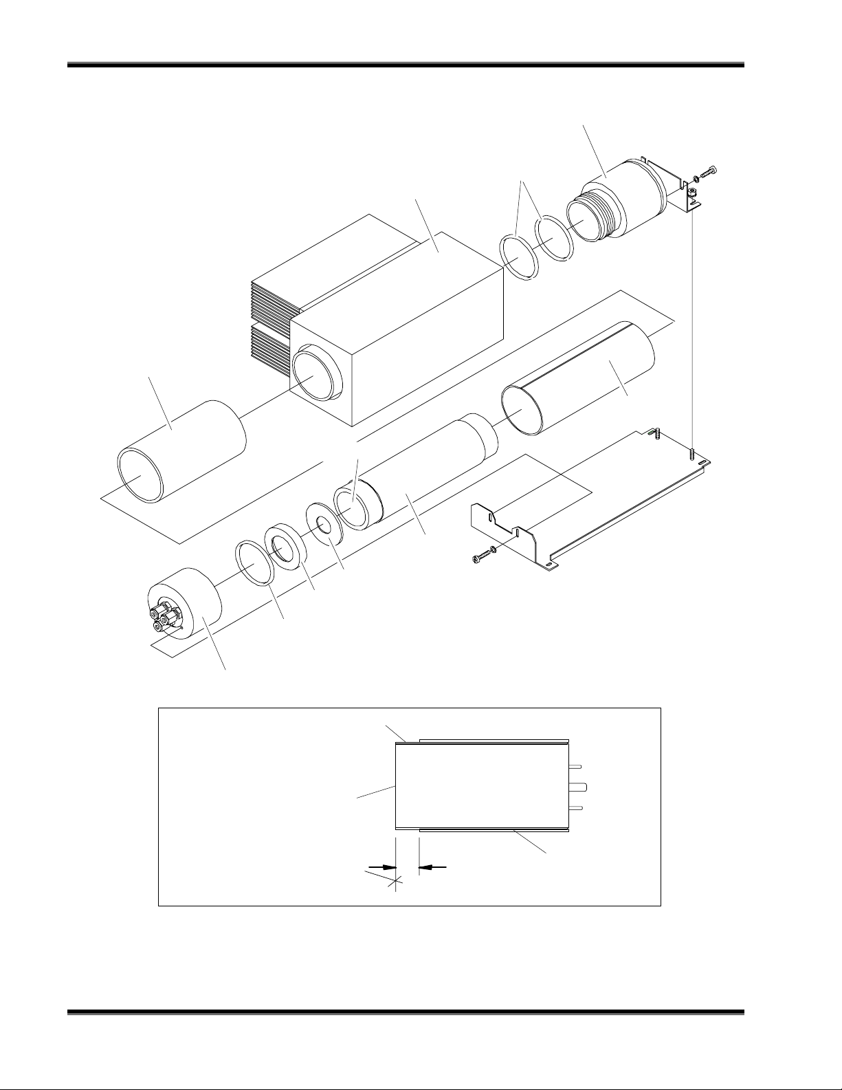
M
951C NOX A
ODEL
Magnetic Shield
636318
NALYZER
Socket Assembly
654086
O-Rings 001522
Thermocooler Housing
654943
PVC Tube
Photomultiplier Tube
655168
Insulating Washer 649541
Thermal Shield 639722
O-Ring 008423
Reaction Chamber 654381
Magnetic Shield
630916
Photomultiplier Tube
Magnetic Shield
630916
Photomultiplier Tube and Magnetic
Shield (PN 630916) to be Flush
Note: Silicone lubricant to be applied to o-rings.
IGURE
F
6-4
6-2. P
Rosemount Analytical
HOTOMULTIPLIER HOUSING ASSEMBLY
September 1997
.3
PVC Tube
748214-N
Page 53
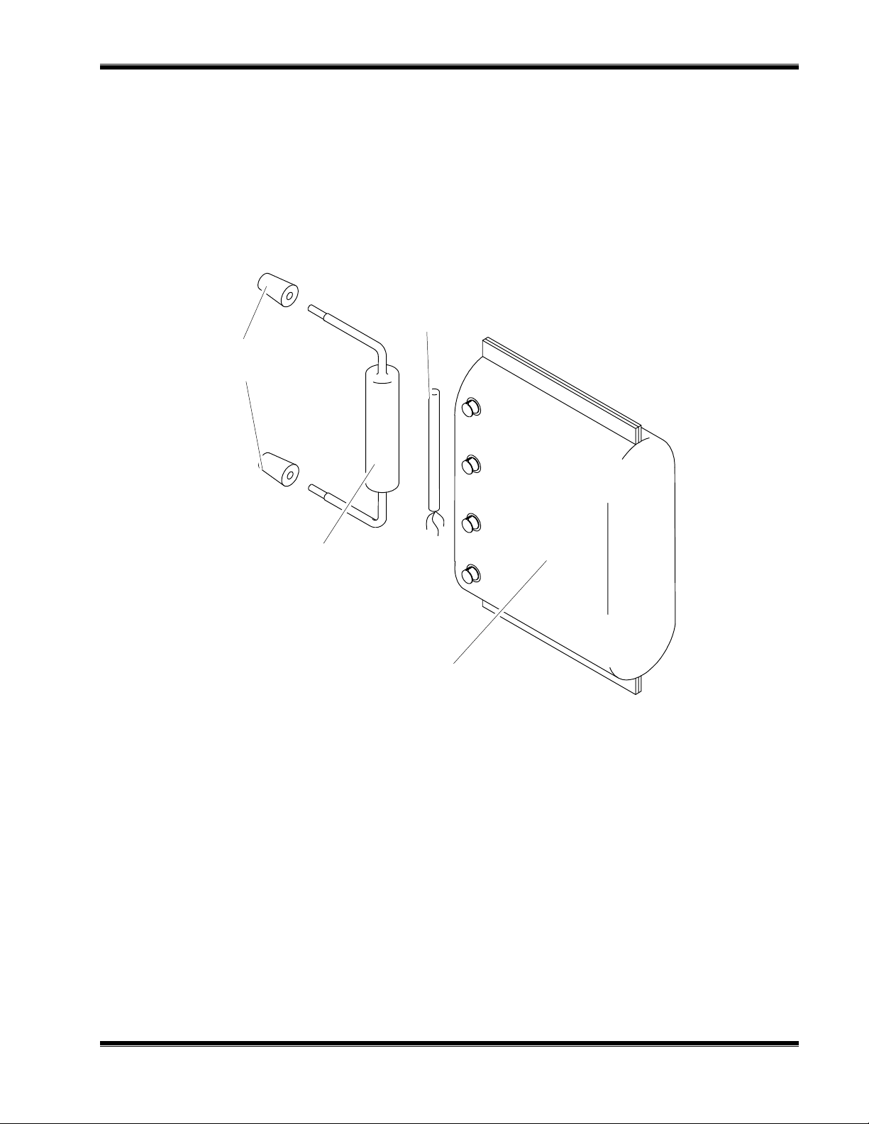
Connectors, Glass
Tube
Temperature Sensor
632782
R
EPLACEMENT PARTS
IGURE
F
6-3. C
Converter Tube - Packed
632795
Heater
657127
ONVERTER ASSEMBLY
748214-N
September 1997
Rosemount Analytical
6-5
Page 54

M
951C NOX A
ODEL
NALYZER
Temperature Control Board
655335
Thermal Fuse
900492
IGURE
F
6-4. C
Heater Cable
Orientation
Fan
622733
Heater
633732
ASE HEATER TEMPERATURE CONTROL ASSEMBLY
6-6
Rosemount Analytical
September 1997
748214-N
Page 55

ENERAL PRECAUTIONS FOR HANDLING AND
G
TORING HIGH PRESSURE GAS CYLINDERS
S
Edited from selected paragraphs of the Compressed
Gas Association's "Handbook of Compressed Gases"
published in 1981
Compressed Gas Association
1235 Jefferson Davis Highway
Arlington, Virginia 22202
Used by Permission
1. Never drop cylinders or permit them to strike each other violently.
2. Cylinders may be stored in the open, but in such cases, should be protected against
extremes of weather and, to prevent rusting, from the dampness of the ground. Cylinders
should be stored in the shade when located in areas where extreme temperatures are
prevalent.
3. The valve protection cap should be left on each cylinder until it has been secured
against a wall or bench, or placed in a cylinder stand, and is ready to be used.
4. Avoid dragging, rolling, or sliding cylinders, even for a short distance; they should be
moved by using a suitable hand-truck.
5. Never tamper with safety devices in valves or cylinders.
6. Do not store full and empty cylinders together. Serious suckback can occur when an
empty cylinder is attached to a pressurized system.
7. No part of cylinder should be subjected to a temperature higher than 125°F (52°C). A
flame should never be permitted to come in contact with any part of a compressed gas
cylinder.
8. Do not place cylinders where they may become part of an electric circuit. When electric
arc welding, precautions must be taken to prevent striking an arc against the cylinder.
4125 E
AST LA PALMA AVENUE
Rosemount Analytical Inc.
• A
J
ULY
, C
NAHEIM
ALIFORNIA
1997 • 748525-C • P
92807-1802 • 714-986-7600 • FAX 714-577-8006
RINTED IN
USA
Page 56

(blank)
Page 57

ARRANTY
W
Goods and part(s) (excluding consumables) manufactured by Seller are warranted to be free from
defects in workmanship and material under normal use and service for a period of twelve (12)
months from the date of shipment by Seller. Consumables, glass electrodes, membranes, liquid
junctions, electrolyte, o-rings, etc., are warranted to be free from defects in workmanship and
material under normal use and service for a period of ninety (90) days from date of shipment by
Seller. Goods, part(s) and consumables proven by Seller to be defective in workmanship and/or
material shall be replaced or repaired, free of charge, F.O.B. Seller's factory provided that the goods,
part(s) or consumables are returned to Seller's designated factory, transportation charges prepaid,
within the twelve (12) month period of warranty in the case of goods and part(s), and in the case of
consumables, within the ninety (90) day period of warranty. This warranty shall be in effect for
replacement or repaired goods, part(s) and the remaining portion of the ninety (90) day warranty in
the case of consumables. A defect in goods, part(s) and consumables of the commercial unit shall
not operate to condemn such commercial unit when such goods, part(s) and consumables are
capable of being renewed, repaired or replaced.
The Seller shall not be liable to the Buyer, or to any other person, for the loss or damage directly or
indirectly, arising from the use of the equipment or goods, from breach of any warranty, or from any
other cause. All other warranties, expressed or implied are hereby excluded.
IN CONSIDERATION OF THE HEREIN STATED PURCHASE PRICE OF THE GOODS, SELLER
GRANTS ONLY THE ABOVE STATED EXPRESS WARRANTY. NO OTHER W ARRANTIES ARE
GRANTED INCLUDING, BUT NOT LIMITED TO, EXPRESS AND IMPLIED WARRANTIES OR
MERCHANTABILITY AND FITNESS FOR A PARTICULAR PURPOSE.
Limitations of Remedy. SELLER SHALL NOT BE LIABLE FOR DAMAGES CAUSED BY DELAY IN
PERFORMANCE. THE SOLE AND EXCLUSIVE REMEDY FOR BREACH OF WARRANTY SHALL
BE LIMITED TO REPAIR OR REPLACEMENT UNDER THE STANDARD W ARRANTY CLAUSE. IN
NO CASE, REGARDLESS OF THE FORM OF THE CAUSE OF ACTION, SHALL SELLER'S
LIABILITY EXCEED THE PRICE TO BUYER OF THE SPECIFIC GOODS MANUFACTURED BY
SELLER GIVING RISE TO THE CAUSE OF ACTION. BUYER AGREES THAT IN NO EVENT
SHALL SELLER'S LIABILITY EXTEND TO INCLUDE INCIDENTAL OR CONSEQUENTIAL
DAMAGES. CONSEQUENTIAL DAMAGES SHALL INCLUDE, BUT ARE NOT LIMITED TO, LOSS
OF ANTICIPATED PROFITS, LOSS OF USE, LOSS OF REVENUE, COST OF CAPITAL AND
DAMAGE OR LOSS OF OTHER PROPERTY OR EQUIPMENT. IN NO EVENT SHALL SELLER BE
OBLIGATED TO INDEMNIFY BUYER IN ANY MANNER NOR SHALL SELLER BE LIABLE FOR
PROPERTY DAMAGE AND/OR THIRD PARTY CLAIMS COVERED BY UMBRELLA INSURANCE
AND/OR INDEMNITY COVERAGE PROVIDED TO BUYER, ITS ASSIGNS, AND EACH
SUCCESSOR INTEREST TO THE GOODS PROVIDED HEREUNDER.
Force Majeure. Seller shall not be liable for failure to perform due to labor strikes or acts beyond
Seller's direct control.
Rosemount Analytical
4125 E
AST LA PALMA AVENUE
Rosemount Analytical Inc.
• A
F
EBRUARY 1997 • 7485189-C • PRINTED IN USA
NAHEIM
, C
ALIFORNIA
92807-1802 • 714-986-7600 • FAX 714-577-8006
Page 58

(blank)
Page 59

IELD SERVICE AND REPAIR FACILITIES
F
Field service and repair facilities are located worldwide.
U.S.A.
To obtain field service on-site or assistance with a service problem, contact (24 hours, 7
days a week):
National Response Center
1-800-654-7768
INTERNATIONAL
Contact your local Rosemount Sales and Service office for service support.
FACTORY
For order administration, replacement Parts, application assistance, on-site or factory repair,
service or maintenance contract information, contact:
Rosemount Analytical Inc.
Process Analytical Division
Customer Service Center
1-800-433-6076
RETURNING PARTS TO THE FACTORY
Before returning parts, contact the Customer Service Center and request a Returned
Materials Authorization (RMA) number. Please have the following information when you call:
Model Number, Serial Number, and Purchase Order Number or Sales Order Number.
Prior authorization by the factory must be obtained before returned materials will be
accepted. Unauthorized returns will be returned to the sende r, f re ight collect.
When return ing any product or compon ent that has been expo sed to a toxic, co rrosive or
other hazardous material or used in such a hazardous environment, the user must attach an
appropriate Material Safety Data Sheet (M.S.D.S.) or a written certification that the material
has been decontaminated, disinfected and/or detoxified.
Return to:
Rosemount Analytical Inc.
4125 East La Palma Avenue
Anaheim, California 92807-1802
4125 E
AST LA PALMA AVENUE
Rosemount Analytical Inc.
• A
J
, C
NAHEIM
ULY 1997 • 748190-G • PRINTED IN USA
ALIFORNIA
92807-1802 • 714-986-7600 • FAX 714-577-8006
Page 60

(blank)
 Loading...