

Page 1

Rosemount Analytical
ODEL
M
XPLOSION PROOF
E
815
ON
N
NSTRUCTION MANUAL
I
ISPERSIVE INFRARED
-D
NALYZER
A
748175-F
Page 2

Notice
Information contained in this document is subject to change without notice.
Irtran™ is a trademark of Eastman Kodak Co.
Pyrex® is a registered trademark of Corning Glass Works.
Teflon® and Viton® are registered trademarks of E.I. du Pont de Nemours & Co., Inc.
Manual Part Number 748175-F
October 1997
Rosemount Analytical
4125 East La Palma Avenue
Anaheim, California 92807-1802
Page 3

C
ONTENTS
P
REFACE
PURPOSE/SAFETY SUMMARY........................................................................P-1
SPECIFICATIONS..............................................................................................P-3
CUSTOMER SERVICE, TECHNICAL ASSISTANCE AND FIELD SERVICE ....P-4
RETURNING PARTS TO THE FACTORY..........................................................P-4
TRAINING ......................................................................................................P-4
DOCUMENTATION............................................................................................P-4
COMPLIANCES..................................................................................................P-5
S
ECTION
1.1 GENERAL DESCRIPTION.......................................................................1-1
1.2 APPLICATIONS........................................................................................1-1
1.3 AVAILABLE OPTIONS..............................................................................1-2
S
ECTION
2.1 UNPACKING..............................................................................................2-1
2.2 LOCATION.................................................................................................2-1
2.3 VOLTAGE REQUIREMENTS....................................................................2-1
2.4 ELECTRICAL CONNECTIONS ................................................................2-2
2.5 SAMPLE CONNECTIONS........................................................................2-2
2.6 CALIBRATION GAS CONNECTIONS AND REQUIREMENTS................2-2
2.7 SAMPLE HANDLING SYSTEM................................................................2-3
2.8 LEAK TEST...............................................................................................2-5
1. I
NTRODUCTION
2. U
2.4.1 Line Power Connections .............................................................2-2
2.4.2 Recorder Connections.................................................................2-2
NPACKING AND INSTALLATION
2.9 OPTIONS..................................................................................................2-6
748175-F Rosemount Analytical October 1997
Model 815 Explosion Proof Non-Dispersive Infrared Analyzer
i
Page 4

C
ONTENTS
S
ECTION
S
ECTION
3.1 LEAK TEST..............................................................................................3-1
3.2 POWER VERIFICATION..........................................................................3-1
3.3 OPERATING CONTROLS AND INDICATORS........................................3-2
3.4 CALIBRATION ..........................................................................................3-3
2. (
2.9.1 Air Purge Kit 652271...................................................................2-6
2.9.2 Current Output Kit 652269..........................................................2-6
2.9.3 Case Heater Temperature Control Kit 652270............................2-7
2.9.4 Linearizer Kit 652268..................................................................2-8
2.9.5 Motor/Source Assembly Purge Kit 655094.................................2-10
3. I
3.3.1 Digital Display.............................................................................3-2
3.3.2 MODE Switch.............................................................................3-2
3.3.3 ZERO Adjustment.......................................................................3-2
3.3.4 SPAN Adjustment.......................................................................3-2
3.4.1 Calibration Procedure.................................................................3-4
3.4.2 Linearizer Board Calibration.......................................................3-4
3.4.3 Calibration Curve Construction...................................................3-5
CONTINUED
NITIAL STARTUP AND CALIBRATION
)
3.5 LINEARIZATION PROCEDURE ..............................................................3-7
3.6 CURRENT OUTPUT................................................................................3-9
S
ECTION
4.1 ROUTINE OPERATION............................................................................4-1
4.2 RECOMMENDED CALIBRATION FREQUENCY.....................................4-1
4.3 SHUTDOWN.............................................................................................4-1
4.4 DETECTION SYSTEM THEORY............................................................. 4-2
4.5 ELECTRONIC CIRCUITRY ...................................................................... 4-3
4. R
4.5.1 Oscillator Circuit Board (Schematic 623995) and
4.5.2 Functioning of Modulation System in TUNE Mode ..................... 4-3
4.5.3 Functioning of Modulation System in Operating Mode...............4-3
4.5.4 Radio-Frequency Demodulator................................................... 4-4
4.5.5 Signal Board (Schematic 652431)..............................................4-4
4.5.6 Power Supply Board (Schematic 624073)..................................4-5
4.5.7 Case Heater Temperature Control Board (Schematic 624003)..4-5
4.5.8 Current Output Board (Schematic 652439) ................................4-5
4.5.9 Linearizer Board (Schematic 624674)........................................4-5
OUTINE OPERATION AND THEORY
Associated Elements of Amplitute Modulation Circuit... 4-3
ii
October 1997 Rosemount Analytical 748175-FModel 815 Explosion Proof Non-Dispersive Infrared Analyzer
Page 5

C
ONTENTS
S
ECTION
5.1 SYMPTOM CHART ..................................................................................5-1
5.2 TEST EQUIPMENT ..................................................................................5-2
5.3 VOLTAGE CHECKS.................................................................................5-2
5.4 OSCILLATOR TUNE ADJUSTMENT .......................................................5-2
5.5 PREAMP GAIN.........................................................................................5-2
5.6 SOURCE BALANCE SHUTTER ADJUSTMENT......................................5-4
5.7 SOURCE ALIGNMENT.............................................................................5-6
5.8 SOURCE CURRENT ADJUSTMENT.......................................................5-6
5.9 TIME CONSTANT.....................................................................................5-6
5.10 CASE HEATER TEMPERATURE CONTROL ASSEMBLY......................5-7
S
ECTION
6.1 CELL REMOVAL, CLEANING AND REPLACEMENT..............................6-2
5. T
5.5.1 Peak Adjustment.........................................................................5-4
6. R
6.1.1 Long Cell Configurations.............................................................6-2
6.1.2 Short Cell Configurations ............................................................6-2
ROUBLESHOOTING
OUTINE SERVICING
6.2 CELL DESICCANT...................................................................................6-4
6.2.1 Desiccant Replacement..............................................................6-4
6.3 SOURCE REPLACEMENT.......................................................................6-5
6.4 CHOPPER MOTOR ASSEMBLY..............................................................6-6
6.4.1 Long Cell Configurations.............................................................6-6
6.4.2 Short Cell Configurations ............................................................6-6
6.5 DETECTOR REPLACEMENT..................................................................6-7
6.5.1 Removal - Long Cell Configurations............................................6-7
6.5.2 Removal - Short Cell Configurations...........................................6-7
6.5.3 Detector Installation.....................................................................6-8
S
ECTION
7.1 CIRCUIT BOARD REPLACEMENT POLICY.............................................7-1
7.2 SELECTED REPLACEMENT PARTS .......................................................7-2
7.3 OPTION KITS...........................................................................................7-2
7. R
7.2.1 Model 815 Common Parts...........................................................7-2
7.2.2 Optical Bench..............................................................................7-2
7.3.1 Linearizer Kit PN 652268 ...........................................................7-2
7.3.2 Current Output Kit PN 652269 ....................................................7-2
EPLACEMENT PARTS
748175-F Rosemount Analytical October 1997
Model 815 Explosion Proof Non-Dispersive Infrared Analyzer
iii
Page 6

C
ONTENTS
S
ECTION
NFRARED CALIBRATION AND DATA SHEET (PER APPLICATION
I
ENERAL PRECAUTIONS FOR HANDLING
G
ARRANTY
W
IELD SERVICE AND REPAIR FACILITIES
F
F
IGURES
1-1 Model 815 Explosion Proof NDIR Analyzer..............................................1-1
2-1 Model 815 Component Locations.............................................................2-3
2-2 Power Supply Board.................................................................................2-4
2-3 Case Heater Temperature Control Board.................................................2-4
2-4 Current Output Board...............................................................................2-7
2-5 Installation of Current Output and Temperature Control Options.............2-8
2-6 Linearizer Board.......................................................................................2-9
2-7 Signal Board with Linearizer Board Installed............................................2-9
3-1 Model 815 Operating Controls and Indicators..........................................3-3
3-2 Signal Board Component Locations.........................................................3-5
3-3 Linearizer Board Adjustments..................................................................3-6
3-4 Typical Linearization Curve......................................................................3-7
3-5 Current Output Board...............................................................................3-9
4-1 NDIR Detection System...........................................................................4-2
4-2 Functional Block Diagram ........................................................................4-6
5-1 Modulation System ................................................................................... 5-5
6-1 Optical Bench...........................................................................................6-3
6-2 Motor/Source Assembly...........................................................................6-6
6-3 Detector Replacement..............................................................................6-9
7-1A Configurations 06, 07, 19, 21, 31, 36, 41, 45, 54, 71, 72, 81....................7-4
7-1B Configurations 35, 73................................................................................7-4
7-1C Configurations 64, 83................................................................................7-5
7-2A Configurations 08, 10, 12, 13, 18, 32, 39, 42, 43, 55, 63, 65, 67..............7-5
7-2B Configurations 22, 23, 29, 30, 33, 34, 38, 76............................................7-6
7-2C Configuration 26.......................................................................................7-6
7-2D Configurations 74, 82, 84..........................................................................7-7
7-3 Case Heater Temperature Control Assembly...........................................7-10
7. (
CONTINUED
7.3.3 Case Heater Temperature Control Kit PN 652270......................7-3
7.3.4 Air Purge Kit PN 652271............................................................7-3
7.3.5 Motor/Source Purge Kit PN 655094............................................7-3
)
)
TORING HIGH PRESSURE CYLINDERS
& S
iv
October 1997 Rosemount Analytical 748175-FModel 815 Explosion Proof Non-Dispersive Infrared Analyzer
Page 7

T
ABLES
3-1 Typical Linearization Calibration Values...................................................3-8
3-2 Linearization Calibration Values ...............................................................3-9
5-1 Troubleshooting Chart..............................................................................5-3
6-1 Types of Desiccant...................................................................................6-5
7-1 Configuration Figure List...........................................................................7-3
7-2 Optical Bench Components by Configuration...........................................7-7
C
ONTENTS
D
RAWINGS (LOCATED IN REAR OF MANUAL
623995 Schematic Diagram, Oscillator Board
624003 Schematic Diagram, Temperature Control Board
624073 Schematic Diagram, Power Supply Board
624674 Schematic Diagram, Linearizer Board
652258 Installation Drawing, Model 815
652259 Pictorial Wiring Diagram, Model 815
652431 Schematic Diagram, Signal Board
652439 Schematic Diagram, Current Output Board
652446 Schematic Diagram, Zero/Span Control Board
)
748175-F Rosemount Analytical October 1997
Model 815 Explosion Proof Non-Dispersive Infrared Analyzer
v
Page 8

C
ONTENTS
N
OTES
vi
October 1997 Rosemount Analytical 748175-FModel 815 Explosion Proof Non-Dispersive Infrared Analyzer
Page 9

P
REFACE
P
URPOSE/SAFETY SUMMARY
To avoid explosion, loss of life, personal injury and damage to this equipment and on-site
property, all personnel authorized to install, operate and service the Model 815 Explosion
Proof Non-Dispersive Infrared Analyzer should be thoroughly familiar with and strictly
follow the instructions in this manual.
If this equipment is used in a manner not specified in these instructions, protective
systems may be impaired.
Save these instructions.
DANGER
personal injury, death, or substantial property damage if the warning is ignored.
WARNING
personal injury, death, or substantial property damage if the warning is ignored.
CAUTION
personal injury or property damage if the warning is ignored.
NOTE
important but not hazard-related.
is used to indicate the presence of a hazard which
is used to indicate the presence of a hazard which
is used to indicate the presence of a hazard which
is used to indicate installation, operation or maintenance information which is
will
cause
can
cause
will or can
cause
severe
severe
minor
WARNING: ELECTRICAL SHOCK HAZARD
Do not operate without doors and covers secure. Servicing requires access to
live parts which can cause death or serious injury. Refer servicing to qualified
personnel.
For safety and proper performance this instrument must be connected to a
properly grounded three-wire source of power.
This instrument is shipped from the factory set up to operate on 115 volt, 50/60
Hz electric power. For operation on 230 volt, 50/60 Hz power, see Section 2.3
and Figures 2-2 and 2-3 for modifications.
748175-F Rosemount Analytical October 1997
Model 815 Explosion Proof Non-Dispersive Infrared Analyzer
P-1
Page 10
P
REFACE
WARNING: POSSIBLE EXPLOSION HAZARD
This analyzer is of a type capable of analysis of sample gases which may be
flammable. If used for analysis of such gases the instrument explosion-proof
enclosure must be suitable for the gas.
WARNING: EXPLOSION HAZARD
If explosive gases are introduced into this analyzer, the sample containment
system must be carefully leak-checked upon installation and before initial
startup, during routine maintenance and any time the integrity of the sample
containment system is broken, to ensure the system is in leak-proof condition.
Leak-check instructions are provided in Section 2.8.
Do not operate the Model 815 Explosion-Proof Analyzer without lens cover and
door in place with all bolts secured, unless location has been determined to be
non-hazardous.
WARNING: HIGH PRESSURE GAS CYLINDERS
This analyzer requires periodic calibration with known zero and standard gases.
Refer to General Precautions for Handling and Storing High Pressure Cylinders,
in the rear of this manual.
WARNING: PARTS INTEGRITY
Tampering or unauthorized substitution of components may adversely affect
safety of this product. Use only factory documented components for repair.
P-2
October 1997 Rosemount Analytical 748175-FModel 815 Explosion Proof Non-Dispersive Infrared Analyzer
Page 11

S
PECIFICATIONS
P
REFACE
P
OWER REQUIREMENTS
A
MBIENT TEMPERATURE
D
IMENSIONS
W
EIGHT
E
NCLOSURE
S
IGNAL OUTPUT
R
EPEATABILITY
N
Z
S
:
OISE
ERO DRIFT
PAN DRIFT
:
:
:
:
:
1
:
1
:
120/220 VAC ±10%, 50/60 ±3 Hz, 150 W;
:
350 W with optional case heater
32°F to 113°F (0°C to 45°C)
:
Some configurations may require optional case heater for temperatures
outside 59°F to 95°F (15°C to 35°C). Refer to Appendix A.
21.5 in (55.0 cm) H
15.5 in. (39 cm) W
11.8 in. (30 cm) D
119 lbs (54 kg)
Explosion Proof, Class I, Groups B,C,D, Division 1.
Mount in weather protected area.
Standard: 0-5 VDC (0-1 VDC field selectable on board)
Optional: 4-20 mA or 0-20 mA (field selectable), 750 ohms max.
1% of fullscale
1% of fullscale
±
1% of fullscale per 24 hours
±
1% of fullscale per 24 hours
R
ESPONSE TIME
(ELECTRONIC
S
AMPLE CELL LENGTH
R
EFERENCE
M
ATERIALS IN CONTACT
S
WITH
WINDOWS
CELLS
TUBING
FITTINGS
S
1
Performance specifications based on ambient temperature shifts of less than 20°F (11°C) per hour.
AMPLE
AMPLE PRESSURE
:
)
:
:
:
:
:
:
:
Variable, 90% of fullscale in 1 sec to 10 sec, field selectable. (Application
dependent)
0.04 in. (1 mm) to 10.0 in. (254 mm)
:
Sealed
Sapphire, quartz, Irtran
Gold plated Pyrex or stainless steel
FEP Teflon
316 stainless steel
Max 10 psig (69 kPa), standard
748175-F Rosemount Analytical October 1997
Model 815 Explosion Proof Non-Dispersive Infrared Analyzer
P-3
Page 12

P
REFACE
C
USTOMER SERVICE
For order administration, replacement Parts, application assistance, on-site or factory
repair, service or maintenance contract information, contact:
R
ETURNING PARTS TO THE FACTORY
Before returning parts, contact the Customer Service Center and request a Returned
Materials Authorization (RMA) number. Please have the following information when
you call:
Number.
Prior authorization by the factory must be obtained before returned materials will be
accepted. Unauthorized returns will be returned to the sende r, f re ight collect.
When returnin g any pro duct o r compon ent t hat has be en expo sed to a toxic, corrosi ve
or other hazardous material or used in such a hazardous environment, the user must
attach an appropriate Material Safety Data Sheet (M.S.D.S.) or a written certification
that the material has been decontaminated, disinfected and/or detoxified.
Model Number, Serial Number, and Purchase Order Number or Sales Order
, T
ECHNICAL ASSIST ANCE AND FIELD SERVICE
Rosemount Analytical Inc.
Process Analytical Division
Customer Service Center
1-800-433-6076
Return to:
Rosemount Analytical Inc.
4125 East La Palma Avenue
Anaheim, California 92807
T
RAINING
A comprehensive Factory Training Program of operator and service classes is
available. For a copy of the
the Technical Services Depart men t at:
D
OCUMENTATION
The following Model 815 Explosion Proof Non-Dispersive Infrared Analyzer instruction
materials are available. Contact Customer Service or the local representative to
order.
748175 Instruction Manual (this document)
Current Operator and Service Training Schedule
Rosemount Analytical Inc.
Phone: 1-714-986-7600
FAX: 1-714-577-8006
contact
P-4
October 1997 Rosemount Analytical 748175-FModel 815 Explosion Proof Non-Dispersive Infrared Analyzer
Page 13

C
OMPLIANCES
The Model 815 Explosion Proof Non-Dispersive Infrared Analyzer is approved by
Factory Mutual for use in Class I, Groups B, C and D Division 1 hazardous locations.
FM
P
REFACE
APPROVED
97-C209
748175-F Rosemount Analytical October 1997
Model 815 Explosion Proof Non-Dispersive Infrared Analyzer
P-5
Page 14

P
REFACE
N
OTES
P-6
October 1997 Rosemount Analytical 748175-FModel 815 Explosion Proof Non-Dispersive Infrared Analyzer
Page 15

I
NTRODUCTION
1
1.1 GENERAL DESCRIPTION
The Model 815 Non-Dispersive Infrared Analyzer is designed to continuously monitor
the concentration of a particular infrared absorbing component of interest in a flowing
gaseous mixture. Concentration is displayed as a percent of fullscale. Signal outputs
of 0-5 VDC or 0-1 VDC are field selectable standard.
The Analyzer enclosure is designed to meet the requirements for Class I, Division 1,
Groups B, C, and D, per the National Electrical Code (ANSI/NFPA 70), and should be
mounted in a weather-protected area.
1.2 APPLICATIONS
Monitoring applications are found in the Application Data Sheet which is available from
the local sales office (see page P-4).
IGURE
F
748175-F Rosemount Analytical October 1997
1-1. M
ODEL
815 E
XPLOSION PROOF
ZERO SPAN
DETECTOR RANGE 1
TUNE RANGE 2
Rosemount Analytical
Model 815
Oxygen Analyzer
NDIR A
Model 815 Explosion Proof Non-Dispersive Infrared Analyzer
NALYZER
1-1
Page 16

I
NTRODUCTION
Some sample streams contain various other infrared-absorbing substances, other than
the component of interest. To minimize interference in such applications, the
instrument may incorporate an optical filter and, if necessary, a sealed filter cell
containing an appropriate gas charge, as noted in the Factory Calibration and Data
Sheet located in the rear of this manual.
1.3 AVAILABLE OPTIONS
Operation of the Model 815 can be enhanced with the choice of several options, all of
which can be installed in the field after the analyzer has been ordered.
IGNAL LINEARIZER
S
A signal linearizer kit is available for each range. Linearizers enable the operator to
convert non-linear output signals into linear output signals.
SOLATED CURRENT OUTPUT
I
The current output option can be field set for either 4-20mA or 0-20mA, corresponding
to 0% to 100% of fullscale. Maximum load is 750 ohms.
ASE TEMPERATURE CONTROLLER
C
A proportional temperature controller, with heater and fan assembly, maintains proper
operating temperature inside the case.
IR PURGE
A
The air purge kit is to be installed with user-supplied components. It is designed for
use in cases where a corrosive gas is either flowing through the cell or is present in
the environment. The air purge option is provided for protection of the instrument only,
and is not intended as a safety feature for use in a hazardous area.
OTOR/SOURCE ASSEMBLY PURGE
M
This purge is recommended in some applications to provide a CO2 free, spectrally
constant atmosphere within the Motor/Source Assembly.
AMPLE HANDLING SYSTEM ACCESSORY
S
If so ordered, an associated sample-handling system may be either factory-assembled
or supplied for field installation, depending on ordering instructions. Sampling systems
are designed on the basis of information furnished by the customer, which includes a
complete stream analysis. Refer to the Factory Calibration and Data Sheet for
information on the sample handling sy stem.
1-2
October 1997 Rosemount Analytical 748175-FModel 815 Explosion Proof Non-Dispersive Infrared Analyzer
Page 17

U
NPACKING AND INSTALLATION
2
2.1 UNPACKING
Carefully examine the shipping carton and contents for signs of damage. Immediately
notify the shipping carrier if the carton or its contents are damaged. Retain the carton
and packing material until the instrument is operational
2.2 LOCATION
Locate the analyzer in a weather-protected location free from vibration. For best
results mount the analyzer near the sample stream to minimize sample-transport time.
Refer to Installation Drawing 652258.
If equipped with P/N 652271 air purge, refer to Section 2.9.1. The air purge is
designed to provide a corrosion-free or spectrally-constant internal atmosphere, and
not intended to provide explosion hazard protection.
is
2.3 VOLTAGE REQUIREMENTS
WARNING: ELECTRICAL SHOCK HAZARD
For safety and proper performance, this instrument must be connected to a
properly grounded three-wire source of electrical power.
Verify that power switch settings are set for the power available at the site (115 VAC or
220 VAC).
Analyzers are shipped from the factory set for 120 VAC, 50/60 Hz operation. To
convert to 220 VAC, 50/60 Hz power, position voltage select switches S1, S2 (located
on Power Supply Board, Figure 2-2), and S3 (located on the optional Case Heater
Temperature Control Board, Figure 2-3), to the 230 VAC position.
Power consumption is less than 150 watts without optional case heater; 350 watts with
optional case heater installed.
748175-F Rosemount Analytical October 1997
Model 815 Explosion Proof Non-Dispersive Infrared Analyzer
2-1
Page 18

U
NPACKING AND INSTALLATION
2.4 ELECTRICAL CONNECTIONS
2.4.1 L
2.4.2 R
INE POWER CONNECTIONS
Refer to Figures 2-1 and 2-5, Installation Drawing 652258 and Pictorial Wiring
Diagram 652559.
Route the power cable (customer supplied 3-wire, minimum 18 AWG) through the
power conduit opening in the bottom of the instrument.
Connect to power terminal block TB1 as follows:
HOT/L1 = TB1-1
NEUTRAL/L2 = TB1-2
GROUND = TB1-3 or TB1-4
ECORDER CONNECTIONS
Refer to Figure 2-1 and 2-5, Installation Drawing 652258 and Pictorial Wiring Diagram
652559.
Route the cable (customer supplied 2-wire shielded cable) through the signal output
conduit opening at the bottom of the enclosure.
Connect to recorder output/curr ent out put terminal block TB2 as follows:
(+)OUTPUT = TB2-1
(- ) OUTPUT = TB2-2
SHIELD (GND) = TB2-3
2.5 SAMPLE CONNECTIONS
Refer to Figure 2-1 and Installation Drawing 652258. Connect sample gas tubing to
the Model 815 through the 1/4-inch ferrule type compression fittings located on the
bottom of the enclosure.
2.6 CALIBRATION GAS CONNECTIONS AND REQUIREMENTS
Refer to Figure 2-1 and Installation Drawing 652258.
Zero and span gases are to be connected to the same inlet fitting as the sample gas.
All applications require a zero standard gas to set the baseline point on the digital
display or output signal. Refer to the Calibration and Data Sheet. Use the background
gas as the zero gas. If a background gas is not specified, use dry nitrogen for the zero
gas.
Span gas concentration is normally between 80% and 100% of the fullscale range the
analyzer will be set on. The background gas is also indicated on the Calibration and
Data Sheet. If no background gas is specified, use dry nitrogen.
2-2
October 1997 Rosemount Analytical 748175-FModel 815 Explosion Proof Non-Dispersive Infrared Analyzer
Page 19

U
NPACKING AND INSTALLATION
2.7 SAMPLE HANDLING SYSTEM
The Model 815 does not contain any filters in the sample flow system to prevent
contamination of the sample lines or cells.
The sample must be clean and kept above the dew point to minimize maintenance and
to prolong the life of the components in the sample flow system. Sample Handling
components and tubing must be constructed of materials compatible with the sample.
Contact the local representative or the factory if an additional sample handling system
is required.
Linearizer Board
(mounted on farside of Signal Board)
(see Figures 2-6 and 2-7)
Power Supply Board
(see Figure 2-2)
Transformer
Motor/Source Assembly
(see Figure 6-2)
Signal Board
(see Figure 2-7)
Span Potentiometer
Zero/Span
Control Board
MODE Switch
Zero Potentiometer
Current Output Board
(see Figure 2-4)
Signal Output
Case Air Purge Inlet
Power
AC Power Terminal
Block TB1
Sample Cell
Sensor, Case Heater
Temperature Control
(see Figure 2-5)
Reference Cell
Detector Assembly
(see Figure 6-3)
Case Heater Temperature Control
Assembly
(see Figure 7-3)
Recorder Output /Current Output
Term inal Block TB2
Fuse
IGURE
F
2-1. M
ODEL
815 C
OMPONENT LOCATIONS
748175-F Rosemount Analytical October 1997
Sample In
Sample Out
Flame Arrestor
Fitting 1/4 inch Tube Connec tor
Model 815 Explosion Proof Non-Dispersive Infrared Analyzer
2-3
Page 20
U
NPACKING AND INSTALLATION
Set switch windows for voltage required
S2 S1
ADAPTER
1
J16
J12
115 115
TEMP
CONTROL
CASE
J5
1
R11
4 3 2 1
S2 S1
230V
115V
DETECTOR
HEATER
J4
1
K1
XFMER
FAN
J2
1
CR4
CR3
CR2
XFMER
C4
+
C2
+
C3
+
C1
S3
SS LUFT
+
+
+
+
VR4
VR3
TP1
R9
TP2
TP1
TP2
R12 R13
8
1
7
6
G
I
2
3
45
C6
+
C12
VR2
VR1
I
C8
G
O
I
G
O
+
+
C10
+
C11
C5
C7
+
C9
+
R1
R2
I
O
G
O
R3
R10
R8
R4
R5
R6
R7
AR1
- CR1 +
R9
C13
U1
+
+
R37
R34
R35
R36
R39
R18
C14
C18
C
E
Q3
1
AR4
C19
J
AR5
R17
CR8
R25
R29
R26
E
C
AK
G
R21
R22
10
C21
J14
1
R
38
1
J11
J8
1
B
Q2
C15
+
J15
R24
R23
1
Q1
1
J13
Q4
U2
R19
R20
R16
R15
C20
C16
R31
R30
R27
R28
R32
R33
B
CR6
CR7
R14
CR5
J7
IGURE
F
IGURE
F
2-2. P
OWER SUPPLY BOARD
SENSOR J18 POWER
400A 880 951E
R10 R11 R7 R8
C2
CR1
R4
C1
C
E
B
+
Q2
Set switch window for voltage required
2-3. C
ASE HEATER TEMPERATURE CONTROL BOARD
Heater LED (CR5)
R17R16 R12CR2
R3
1
AR1
R13
R2R1
Q1
K
G
A
TEMP CONTROL BD
S3
J11
J19
TEST
POWER
LINE
J5
R15
R14
1 2 1 2 3
T.I.F. HEATER
C4
3 2 1
U2
1
2
3
1
U1
S3
230
115
J17
115
SUPPLY
R6
C3
R9 R5
CR3
1
E
B
Q3
C
2-4
October 1997 Rosemount Analytical 748175-FModel 815 Explosion Proof Non-Dispersive Infrared Analyzer
Page 21

U
NPACKING AND INSTALLATION
2.8 LEAK TEST
Any leakage must be corrected before introduction of sample and/or application of
electrical power.
WARNING: POSSIBLE EXPLOSION HAZARD
This analyzer is of a type capable of analysis of sample gases which may be
flammable. If used for analysis of such gases the instrument explosion-proof
enclosure must be suitable for the gas.
If explosive gases are introduced into this analyzer, the sample containment
system must be carefully leak-checked upon installation and before initial
startup, during routine maintenance and any time the integrity of the sample
containment system is broken, to ensure the system is in leak-proof condition.
Leak-check instructions are provided in this section.
Internal leaks resulting from failure to observe these precautions could result in
an explosion causing death, personal injury or property damage.
The following test is designed for sample pressure up to 10 psig (69 kPa).
1. Connect air (or other inert gas such as nitrogen) at 10 psig (69 kPa) to analyzer via
a flow indicator and set flow rate to fullscale at the sample inlet (unless otherwise
specified by the Calibration and Data Sheet.
2. Seal off sample outlet with a cap while air or inert gas is flowing into the sample
inlet. If the flowmeter reading drops to zero, the system is leak free. If the
flowmeter does not drop to zero, a leak in the system is present and must be
located and sealed before operating the Model 815.
Note:
Whether or not a leak is suspected, the sample flow system should be leak
checked under pressure before the analyzer is placed in operation.
3. Refer to the note below, then liberally cover the outlet plug and all gas connections
with a suitable test liquid such as SNOOP (PN 837810) to detect leaks. Apply to all
fittings, seals, and other possible leak sources. Bubbling or foaming indicates
leakage, but the absence of bubbles does not necessarily indicate that no leaks
exist.
4. If a flow is indicated, a leak is present and may be in an area that is inaccessible to
SNOOP. Continue leak testing and tighten all connections until the flow rate drops
to zero.
748175-F Rosemount Analytical October 1997
Model 815 Explosion Proof Non-Dispersive Infrared Analyzer
2-5
Page 22

U
NPACKING AND INSTALLATION
Note:
Do not allow test liquid to contaminate cells, detector or source windows.
Should this occur, the cells should be cleaned (Section 6.1).
2.9 OPTIONS
The following options may be ordered as kits and installed in the field:
2.9.1 A
IR PURGE KIT
652271
WARNING: POSSIBLE EXPLOSION HAZARD
If an air purge is used, the purge inlet fitting must be equipped with a Flame
Arrestor Assembly (PN 638426) to prevent propagation of a flame or explosion
from inside the enclosure to the ambient atmosphere.
All precautions relating to the installation and operation of this instrument must
be strictly adhered to whether or not the air purge option is installed.
purge option is not intended as protection from explosion in hazardous areas.
Purging of the enclosure of the explosion-proof Model 815 may be recommended in
some applications to provide a corrosion free internal atmosphere. If the instrument is
to be equipped with an optional Air Purge Kit, refer to instruction sheet (748184)
supplied in kit for installation. This kit is designed to provide a corrosion free or
spectrally-constant internal atmosphere, and
hazard protection.
2.9.2 C
URRENT OUTPUT KIT
652269
is not intended to provide explosion
The air
2-6
Refer to Figures 2-1, 2-2, 2-4, 2-5, Pictorial Wiring Diagram 652259 and installation
Drawing 652258.
NSTALLATION
I
1. Mount the Current Output Board to the chassis next to the Power Supply Board
using the spacer and hex nut supplied in the kit.
2. Connect the two-wire cable supplied in kit (PN 749068) as follows:
Wire From To
Blue
Orange
Current Output Board
TB1-1 (-)
Current Output Board
TB1-2 (+)
Recorder Output/Current Output Terminal
Block TB2-5 (Current Output -)
Recorder Output/Current Output Terminal
Block TB2-4 (Current Output +)
October 1997 Rosemount Analytical 748175-FModel 815 Explosion Proof Non-Dispersive Infrared Analyzer
Page 23

U
NPACKING AND INSTALLATION
3. Connect the eight conductor flat cable supplied in kit (PN 652257) from Current
Output Board J2 to Power Supply Board J9.
4. Refer to Section 3.6 for 4-20mA or 0-20mA adjustment procedur e.
2.9.3 C
ASE HEATER TEMPERATURE CONTROL KIT
652270
Refer to Figures 2-1, 2-2, 2-3, 2-5, 7-3 and Pictorial Wiring Diagram 652259.
NSTALLATION
I
1. Mount the Temperature Control Assembly to the chassis with the 4 screws
supplied in the kit.
2. Attach the sensor (at T.I.F. 2-position terminal block) to the reference cell with a
tie wrap as shown in Figure 2-1.
3. Connect the 3-conductor cable supplied in kit (PN 622903) from Temperature
Control Board J5 to Power Supply Board J5.
4. Connect the 8-conductor flat cable supplied in kit (PN 901768) from Temperature
Control Board J11 to Power Supply Board J11.
Baseline Current
Output Adjust
(0 or 4mA)
IGURE
F
Fullscale Current
Output Adjust
(20mA)
2-4. C
URRENT OUTPUT BOARD
ZERO
SPAN
C4
+
R7
CR2
R9
CR3
U6
R1
1
1
R2
U2
U1
U3
1 2 3 4
C5
+
+
C9
+
C8
+
C5
+
C7
C1
+
C2
+
U4
C3
MA
V/I 652442 BD
I G O
+ CR1
U5
TB1
-
+
J2
J1
1
O
G
I
To Power Supply Board
J12
To Recorder Output/Current
Output Terminal Block TB2
748175-F Rosemount Analytical October 1997
Model 815 Explosion Proof Non-Dispersive Infrared Analyzer
2-7
Page 24

U
q
NPACKING AND INSTALLATION
Ref Power Supply Board
Ref - Fuse
SPACER
Ref - TB1
Line Power
J2
CURRENT
OUTPUT
BOARD
TB1
SCREW
NUT
6-32
4 Re
J5
SENSOR
See Figure 2-1 for
mounting location.
uired
J1
Ref - TB2
Recorder
Output/
Current Output
TEMPERATURE
CONTROL ASSEMBLY
See Figure 7-3.
IGURE
F
2.9.4 L
Refer to Figures 2-1, 2-6, 2-7 and Pictorial Wiring Diagram 656659
NSTALLATION
I
1. Mount the Linearizer Board to the Signal Board by inserting the 6-pin header on
2. Secure the Linearizer Board to the Signal Board with the screw, lock washer and
2-8
2-5. I
INEARIZER KIT
NSTALLATION OF CURRENT OUTPUT AND TEMPERATURE CONTROL
PTIONS
O
652268
the wiring side of the Linearizer Board into the 6-position single-in-line socket on
the Signal board. The through hole on the Linearizer Board (next to R19) should
be in-line with the swaged threaded spacer on the Signal Board.
flat washer supplied in the kit.
October 1997 Rosemount Analytical 748175-FModel 815 Explosion Proof Non-Dispersive Infrared Analyzer
Page 25

IGURE
F
2-6. L
6 Pin
Header
INEARIZER BOARD
R5
R6
R7
R8
R9
1
RP1
R10
R11
R12
LINEARIZER BD
1
R1
R2
1
CR2
1
1RP2
1
1
CR1
U5
R3
R4
R14
U1
U2
U3
U4
Through Hole
U
NPACKING AND INSTALLATION
LIN
OFF
TP1
SW1
TP2
ON
0
R15
R16
1
2
R17
3
R18
4
R19
5
R20
6
R21
7
R22
8
R23
S
SW2
TP3
R13
TP4
R24
CAL
C
R50 R4 R2 R1
C3
ZERO/SPAN
CONTROL
C2
J8
1
R46 C20 C22 R34 R29
POWER SUPPLY
J3
1
J7
1
C1
R7
C7
R60 R11 R10
DISPLAY
U9
R54 R56 R55 R57
C5
U1
R5
CR1
C4
R8 R9 R16 R14 R15 R21
U2
C9
C8
U4
R13 R18 R19
R49Y1R33 R45 R44
C21
C25 C24 R59 R58
U13
C6
R6
U3
J1
1
OSCILLATOR
METER RECORDER
1
J6
R20 R23
R31
C10
C23
U11
C12
U5
C16
U8
C14
U7
C18 R42 C18
1
TP1 TP2 TP3 TP4 TP5 TP6 TP7
SW2
R22
C11
SEC 1 2 5 10
C13 R24 R25 R26 R27 R35 R52 R36
C15
R32
R30 R40 R51
G
U6
J2
TEST
O
I
R5
R6
R7
R8
R9
RP1
J4
R10
R11
R12
LINEARIZER BD
1
GAIN PEAK BALANCE
R3
R53
U12
1
U1
1
U2
1
U3
1
U4
1
U5
R12
R47
R48
C26
U10
C17 R41 R38
R1
R2
R3
R4
CR2
1RP2
CR1
R13
R14
SIGNAL BD
6-Pin Header located on farside of Linearizer Board
CR2
E1
SW1
SW2
ZERO
R28
R37
SW1
E2
(1)LC
(2)HC
R39
LIN
OFF
ON
0
1
2
3
4
5
6
CAL
7
8
S
C
Screw, Lock Washer and
Flat Washer supplied in
Linearizer Kit
R17
TP1
TP2
R15
R16
R17
R18
R19
R20
R21
R22
R23
TP3
TP4
R24
IGURE
F
2-7. S
IGNAL BOARD WITH LINEARIZER BOARD INSTALLED
748175-F Rosemount Analytical October 1997
Model 815 Explosion Proof Non-Dispersive Infrared Analyzer
2-9
Page 26

U
NPACKING AND INSTALLATION
2.9.5 M
OTOR/SOURCE ASSEMBLY PURGE KIT
655094
WARNING: POSSIBLE EXPLOSION HAZARD
If a motor/source purge is used, the purge inlet fitting must be equipped with a
Flame Arrestor Assembly (PN 638426) to prevent propagation of a flame or
explosion from inside the enclosure to the ambient atmosphere.
All precautions relating to the installation and operation of this instrument must
be strictly adhered to whether or not the air purge option is installed. The air
purge option is not intended as protection from explosion in hazardous areas.
Purging of the Model 815 motor/source assembly may be installed or recommended in
some applications to provide CO
instruction sheet (748256) supplied in kit. This kit
explosion hazard protection.
NSTALLATION
I
2
free, spectrally-constant atmosphere. Refer to
is not intended to provide
Refer to instruction sheet (748256) supplied in kit
2-10
October 1997 Rosemount Analytical 748175-FModel 815 Explosion Proof Non-Dispersive Infrared Analyzer
Page 27

I
NITIAL STARTUP AND CALIBRATION
3
Prior to shipment, the Model 815 was subjected to extensive factory performance
testing, during which all necessary optical and electrical adjustments were made.
Normally, the analyzer requires only a verification of zero and span settings (refer to
Section 3.3) before being put into operation. If operation is unsatisfactory, refer to
Section 5, Troubleshooting. If the problem is not corrected, contact the nearest field
service facility (see Field Service and Repair Facilities in rear of this manual).
The following instructions are recommended for initial start-up, and subsequent
standardization of the analyzer.
WARNING: POSSIBLE EXPLOSION HAZARD
If explosive gas samples are introduced into the analyzer, it is recommended
that sample containment system fittings and components be thoroughly leak
tested prior to initial application of electrical power, routinely on a periodic basis
thereafter, and after any maintenance which entails breaking the integrity of the
sample containment system. Leakage of flammable samples could result in an
explosion. Refer to leak test procedure, Section 2.8.
3.1 LEAK TEST
Per Section 2.8, perform the Leak Test.
3.2 POWER VERIFICATION
1. Verify power select switches S1, S2 (on Power Supply Board) and S3 (on
Temperature Control Board)are set for available power (115 VAC/220 VAC). Refer
to Section 2.3.
2. Verify electrical connections are correct. Refer to Section 2.
3. Apply power. Verify that heater LED (CR5 on the Power Supply Board) is ON.
Refer to Figure 2-2 and Drawing 624073.
748175-F Rosemount Analytical October 1997
Model 815 Explosion Proof Non-Dispersive Infrared Analyzer
3-1
Page 28

I
NITIAL STARTUP AND CALIBRATION
3.3 OPERATING CONTROLS AND INDICATORS
External controls (located on the analyzer door) are described in the following section.
Refer to Figure 3-1.
3.3.1 D
IGITAL DISPLAY
3 1/2 digit LCD displays sample data or oscillator tuning check, depending on position
of the 4-position MODE switch (see Section 3.3.2).
During linearization, a calibration curve is used to convert display readings into
concentration values. (Alternatively, linear readout of concentration values for a given
operating range is obtainable through use of an optional signal output linearizer
board.)
3.3.2 MODE S
WITCH
A 4-position rotary switch for selection of the following:
TUNE -
Test position used periodically to verify and adjust proper oscillator tuning. In
TUNE mode, digital display should indicate the previously determined “Normal Tuning
Value.” If not, adjust the OSC TUNE (refe r to Section 5.4 Oscillator Tune Adjustment).
DETECTOR RANGE 1
To adjust preamp gain (see Section 5.5 Preamp Gain Adjustment).
-
Low concentration range.
Percent of fullscale of the lower concentration
range is displayed on the digital display and a proportional signal is output at Recorder
Output/Current Output Terminal Block TB2.
RANGE 2
range is displayed on the digital display and a proportional signal is output at Recorder
Output/Current Output Terminal Block TB2.
3.3.3 ZERO A
To adjust zero point on digital display or signal output.
3.3.4 SPAN A
To adjust calibration span point on display or signal output.
3-2
-
High concentration range.
DJUSTMENT
DJUSTMENT
Percent of fullscale of the lower concentration
October 1997 Rosemount Analytical 748175-FModel 815 Explosion Proof Non-Dispersive Infrared Analyzer
Page 29

Digital Display
(see Section 3.3.1)
I
NITIAL STARTUP AND CALIBRATION
SPAN Adjustment
(see Section 3.3.4)
IGURE
F
ZERO Adjustment
(see Section 3.3.3)
MODE Switch
(see Section 3.3.2)
3-1. M
ODEL
815 O
ZERO SPAN
DETECTOR RANGE 1
TUNE RANGE 2
Rosemount Analytical
Model 815
Oxygen Ana l yzer
PERATING CONTROLS AND INDICATORS
3.4 CALIBRATION
CAUTION: HIGH PRESSURE GAS CYLINDERS
This analyzer requires periodic calibration with known zero and standard gases.
Refer to General Precautions for Handling and Storing High Pressure Cylinders,
in the rear of this manual.
Note:
Refer to the Factory Calibration and Data Sheet at the end of this manual for
specifications of the calibration gases and procedures.
Note:
Component electronic offsets will shift slightly as the interior temperature of the
instrument changes. For this reason, it is recommended that immediately prior
to adjustment of the electronics, the instrument be allowed to run with the
enclosure door securely closed for at least two hours (or long enough for the
instrument to reach its regulated operating temperature).
748175-F Rosemount Analytical October 1997
Model 815 Explosion Proof Non-Dispersive Infrared Analyzer
3-3
Page 30

I
NITIAL STARTUP AND CALIBRATION
Clean, dry nitrogen is recommended for use as the zero gas, unless otherwise
specified on the data sheet. Span gas is typically 80-100% of the fullscale
concentration of the range being used. Background composition of the span gas is
typically as similar to the composition of the sample being monitored as practical.
3.4.1 C
ALIBRATION PROCEDURE
Refer to Figures 2-1 and 3-1.
1. Connect zero or span gases to the sample
connection port on the bottom of
inlet
the enclosure.
2. Set the calibration gas flow rate to the same flow rate as the sample being
analyzed, typically 1-2 SCFH (500-1000 /min.), and at the same pressure as the
sample gas. Note that the analyzer is not flow rate dependent; however,
calibration and sampling conditions should always be as similar as possible.
3. Monitor the signal at the recorder output or the analyzer digital display.
4. Introduce zero gas through the sample inlet, and set the ZERO adjustment for a
reading of zero output.
5. Set the MODE switch to RANGE 2 (high range). Introduce a span gas of 80-100%
fullscale. Set the SPAN adjustment for the corresponding voltage.
For example, if fullscale is 10% and the span gas is 8.5%, adjust the span screw
for 85% of fullscale, if linearizer is installed. If linearizer is not used, refer to the
Calibration and Data Sheet.
6. Set the MODE switch to RANGE 1 (Low Range), introduce a low range span gas,
and check the output for the correct value. If the lower range span gas value
agrees with the calculated value, the analyzer has been calibrated correctly.
If the output value does not agree, verify the concentration of the span gas.
3.4.2 L
Linearizers ordered with the instrument are calibrated at the factory for the particular
operating range specified by the order and should need no further adjustment.
To verify proper operation, connect different concentrations of span gas to the sample
inlet and record the output signal or digital display (on analyzer door) reading. Plot th e se
values versus concentration (typical curve shown in Figure 3-4). If the curve is linear,
the linearizer for that range is properly calibrated.
If the calibration curve is not linear, perform one of the following calibration
procedures.
The first method requires use of a DVM; the second uses recorder output.
3-4
INEARIZER BOARD CALIBRATION
October 1997 Rosemount Analytical 748175-FModel 815 Explosion Proof Non-Dispersive Infrared Analyzer
Page 31

I
NITIAL STARTUP AND CALIBRATION
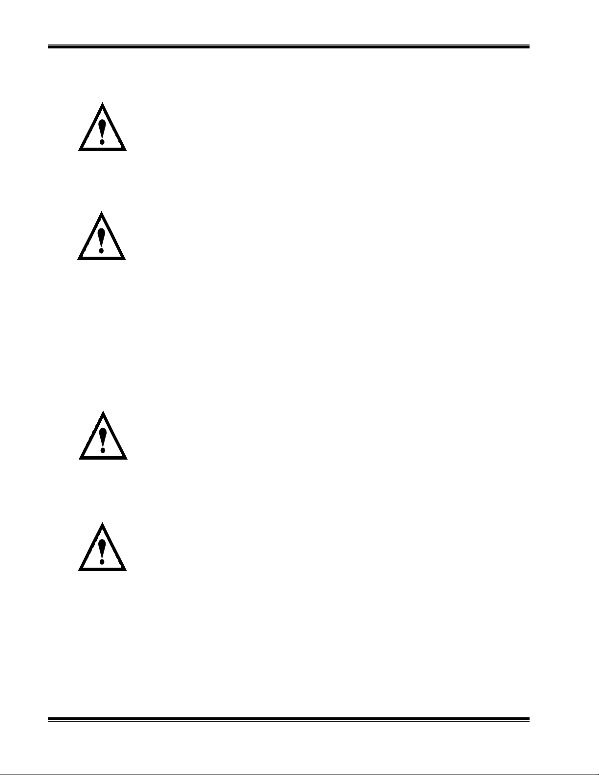
3.4.3 C
ALIBRATION CURVE CONSTRUCTION
A typical calibration curve showing the relationship between the non-linearized and
linearized output is shown in Figure 3-4. The curve is a plot of signal output versus
concentration. Examples of curves normalized for concentration and for recorder
output are shown in Figure 3-4.
Zero Potentiometer R28
Not active on Model 815
Span Potentiometer
R37 For low
concentration
Range Switch SW1
Not active on Model
815
Span Potentiometer
R39
DIP Switch SW2
Time Constant Select
SW2
SEC 1 2 5 10
Jumper E2 - High Concentration
Note: Must be installed if
Linearizer Board not installed.
Jumper E1 - Low Concentration
Note: Must be installed if
Linearizer Board not installed.
Peak Potentiometer R12
Gain Potentiometer R3
Jumper E3
0 to 5 VDC
E3
GAIN PEAK
R12
R3
ZERO
R28
R37
SW1
E2
E1
R39
(1)LC
(2)HC
R50 R4 R2 R1
C3
ZERO/SPAN
CONTROL
C2
J8
1
R46 C20 C22 R34 R29
POWER SUPPLY
J3
1
J7
1
C1
R7
C7
R60 R11 R10
DISPLAY
U9
R54 R56 R5 5 R57
C5
U1
R5
CR1
C4
R8 R9 R16 R14 R15 R21
U2
C9
C8
U4
R13 R18 R1 9
R49Y1R33 R45 R4 4
C21
C25 C24 R59 R58
U13
C6
R6
U3
J1
1
OSCILLATOR
METER REC ORDER
1
J6
R20 R23
R31
C10
C23
U11
TP2
TP1 TP2 TP3 TP4 TP5 TP6 TP7
C11
C12
U5
C16
U8
R32
C14
U7
R30 R40 R5 1
G
U6
C18 R42 C18
1
J2
TEST
TP6
SW2
R22
SEC 1 2 5 10
C13 R24 R25 R26 R27 R35 R52 R36
C15
R5
R6
R7
R8
R9
1
I
RP1
J4
R10
R11
R12
LINEARIZER BD
O
TP7
GAIN PEAK BALANCE
R3
R53
U12
1
U1
1
U2
1
U3
1
U4
1
SIGNAL BD
R12
R47
R48
C26
U10
C17 R41 R38
CR2
1RP2
CR1
U5
R14
CR2
E1
R15
R16
R17
R18
R19
R20
R21
R22
R24
R23
E2
SW1
SW2
SW1
ZERO
R28
R37
(1)LC
(2)HC
R39
LIN
OFF
ON
0
1
CAL
2
3
4
5
6
7
8
S
C
Linearizer Board
See Figure 3-3.
R17
TP1
R1
R2
TP2
R3
R4
TP3
R13
TP4
IGURE
F
3-2. S
IGNAL BOARD COMPONENT LOCATIONS
748175-F Rosemount Analytical October 1997
Model 815 Explosion Proof Non-Dispersive Infrared Analyzer
3-5
Page 32

I
NITIAL STARTUP AND CALIBRATION
R5
R6
R7
R8
R9
1
RP1
R10
R11
R12
LINEARIZER BD
U1
U2
U3
U4
1
1
CR2
1
1RP2
1
1
CR1
U5
R14
R1
R2
R3
R4
R13
TP4
TP1
TP1
TP2
R15
R16
R18
R19
R20
R21
R22
TP3
TP4
R24
R17
R23
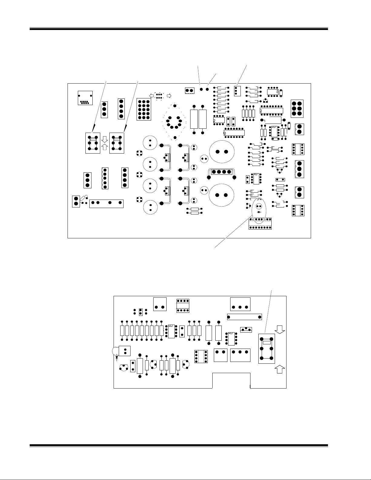
SW1
SW2
LIN
CAL
OFF
ON
S
C
Slide Switch SW1
Linearize ON/OFF
0
1
2
3
4
5
6
7
8
Linearizer Potentiometers
Slide Switch SW2 Signal Selection:
S = Signal
C = Calibration
IGURE
F
3-3. L
INEARIZER BOARD ADJUSTMENTS
To construct a new calibration curve, use the following procedure:
1. Determine the fullscale range to be calibrated. On the Linearizer Board (Figure 3-
3) set SW1 to OFF.
2. Obtain calibration gases (or use a dilution system) of concentrations from 0-100%
fullscale in 10% increments.
3. Introduce the zero gas and note the recorder output voltage (or digital display
reading).
4. Repeat step 3 using the other calibration gases.
5. Normalize the readings, so that 100% fullscale is 1 and 0% is 0. Plot the
concentration versus linearizer output on a graph similar to Figure 3-4.
6. Draw a straight line from the 0% data point to the 100% point. This will be the
linear output after the linearizer is properly adjusted.
7. Segment the line into eight equal points for an 8-point linearization. Draw the
vertical lines from each of the data points to the straight line. From where the
vertical lines intersect the straight line, draw horizontal line to the right axis. The
value on the right axis will be the value to which each data point will be adjusted.
3-6
8. Enter the values in Table 3-2, using Table 3-1 as a guide. These values will be
used to perform Section 3.5.3 Line ari zation Procedure.
9. The linearizer can now be adjusted using potentiometers R15 through R23 on the
Linearizer Board (Figure 3-3).
October 1997 Rosemount Analytical 748175-FModel 815 Explosion Proof Non-Dispersive Infrared Analyzer
Page 33

I
NITIAL STARTUP AND CALIBRATION
SIGNAL IN
(NORMALIZED)
Refer to Calibration and
Data Sheet for the curve
corresponding to the
application specified for this
Model 815.
IGURE
F
3-4. T
YPICAL LINEARIZA TION CURVE
1
0.875
0.750
0.625
0.500
0.375
0.250
0.125
0
0 1
CONCENTRATION NORMALIZED
1
0.8274
0.6696
0.5266
0.3974
0.2812
0.1770
0.0838
0
SIGNAL OUT
(NORMALIZED)
3.5 LINEARIZATION PROCEDURE
WARNING: EXPLOSION HAZARD
Do not operate the Model 815 Explosion-Proof Analyzer without lens cover and
door in place with all bolts secured, unless location has been determined to be
non-hazardous.
1. Locate analyzer in a non-hazardous area before opening the enclosure door.
2. Allow the analyzer to warm-up for a minimum of two hours prior to calibration.
3. Remove the bolts fastening the enclosure door to access the Linearizer Board
which is mounted to the Signal Board inside the enclosure door (see Figure 2-1).
4. On the Linearizer Board (Figure 3-3):
a. Set SW2 to C (Calibration)
b. Connect a DVM to TP4
c. Set SW1 to ON
d. Connect another DVM to TP1
748175-F Rosemount Analytical October 1997
Model 815 Explosion Proof Non-Dispersive Infrared Analyzer
3-7
Page 34

I
NITIAL STARTUP AND CALIBRATION
5. Adjust R16 through R23 full counterclockwise.
6. Refer to Table 3-2 or the Calibration and Data Sheet and make the following
adjustments: (Note: Adjusting R24 simulates an input signal to the Linearizer
Board. R15 through R23 are adjusted to bring the output signal at the level onto
the linear curve.)
a. Adjust R24 so TP4 reads 0 volts.
b. Adjust R15 so TP1 reads 0 volts.
c. Adjust R24 so TP4 reads 0.625 volts.
d. Adjust R16 so TP1 reads 0.419 volts (or the value indicated in the Calibration
and Data Sheet or Table 3-2).
e. Adjust R24 so TP4 reads 1.25 volts.
f. Adjust R17 so TP1 reads 0.885 volts (or the value indicated in the Calibration
and Data Sheet or Table 3-2).
g. Continue with the remaining potentiometers (R18 through R23), adjusting R24
to each value in column 3 of Table 3-2, and then adjusting R18 through R23 to
each value in column 5.
7. Set SW2 to S (Signal).
8. The Linearizer Board is now calibrated.
INPUT VOLTAGE TO LINEARIZER AT TP4
Reading to be obtained by setting SW2 to C (CAL) and
adjusting potentiometers R15 through R23
% FULLSCALE
0.0 0.000 0.000 R15 0.000 0.000
12.5 0.125 0.625 R16 0.084 0.419
25.0 0.250 1.250 R17 0.177 0.885
37.5 0.375 1.875 R18 0.281 1.405
50.0 0.500 2.500 R19 0.397 1.987
62.5 0.625 3.125 R20 0.527 2.633
75.0 0.750 3.750 R21 0.670 3.348
87.5 0.875 4.375 R22 0.827 4.137
100.0 1.000 5.000 R23 1.000 5.000
TEST METER RE AD I N G
on Linearizer Board
NORMALIZED
VALUE/GRAPH
VOLTAGE AT TP4 POTENTIOMETER
Reading at TP1 obtained with the specified linearizer
LINEARIZED OUTPUT
potentiometer
NORMALIZED
VALUE/GRAPH
VOLTAGE AT TP1
ABLE
T
3-8
3-1. T
YPICAL LINEARIZA TION CALIBRATION VALUES
October 1997 Rosemount Analytical 748175-FModel 815 Explosion Proof Non-Dispersive Infrared Analyzer
Page 35

I
NITIAL STARTUP AND CALIBRATION
INPUT VOLTAGE TO LINEARIZER AT TP4
TEST METER RE AD I N G
Reading to be obtained by setting SW2 to C (CAL) and
adjusting potentiometers R15 through R23
Reading at TP1 obtained with the specified linearizer
on Linearizer Board
% FULLSCALE
NORMALIZED
VALUE/GRAPH
VOLTAGE AT TP4 POTENTIOMETER
R15
R16
R17
R18
R19
R20
R21
R22
R23
ABLE
T
3-2. L
INEARIZA TION CALIBRATION VALUES
3.6 CURRENT OUTPUT
The current output board can be adjusted for 4-20mA or 0-20mA.
LINEARIZED OUTPUT
potentiometer
NORMALIZED
VALUE/GRAPH
VOLTAGE AT TP1
Refer to Figure 3-5. Adjust potentiometer R1 for the baseline output current (0 or
4mA), and R2 for the fullscale output (20mA).
Fullscale Current Output
Adjust (20mA)
Baseline Current Output
Adjust (0 or 4mA)
IGURE
F
3-5. C
U6
R1
1
ZERO
1
R2
SPAN
C4
U2
+
U3
R7
CR2
R9
CR3
1 2 3 4
URRENT OUTPUT BOARD
U1
C5
+
+
C9
+
C8
+
C5
+
C7
C1
+
C2
+
U4
C3
MA
V/I 652442 BD
I G O
+ CR1
U5
TB1
-
+
J2
J1
1
O
G
I
748175-F Rosemount Analytical October 1997
Model 815 Explosion Proof Non-Dispersive Infrared Analyzer
3-9
Page 36

I
NITIAL STARTUP AND CALIBRATION
N
OTES
3-10
October 1997 Rosemount Analytical 748175-FModel 815 Explosion Proof Non-Dispersive Infrared Analyzer
Page 37

R
OUTINE OPERATION AND THEORY
4
4.1 ROUTINE OPERATION
As a check of instrument performance, a log book should be kept with the analyzer for
recording notes on operation, calibration, performance and maintenance.
4.2 RECOMMENDED CALIBRATION FREQUENCY
The calibration interval should be determined by the user based on the accuracy
required. Initially, the instrument should be calibrated every 24 hours until experience
indicates that some other interval is more appropriate.
If barometric pressure changes significantly, recheck the calibration against an
upscale standard gas. A change in cell pressure of 1 inch of mercury (3 kPa) will
result in a readout error of approximately 3% of reading.
4.3 SHUTDOWN
Instrument power is normally left on at all times except during a prolonged shutdown
or maintenance.
1. To shutdown the instrument:
2. Disconnect electrical power.
3. If hazardous samples have been flowing through the analyzer, adequate venting of
the gases and adequate ventilation must be provided for before disconnecting
sample lines from the analyzer.
4. Inspect the sample lines and “wetted” parts of the analyzer, clean if necessary.
5. Flush sample lines and analyzer cell with dry nitrogen or dry air, verify that they are
dry.
6. Plug sample lines.
Following prolonged shutdown, repeat Section 2.8 Leak Test, Section 3.1 Initial
Startup and Calibration to restore analyzer to service.
748175-F Rosemount Analytical October 1997
Model 815 Explosion Proof Non-Dispersive Infrared Analyzer
4-1
Page 38

R
OUTINE OPERATION AND THEORY
4.4 DETECTION SYSTEM THEORY
As shown in Figure 4-1, infrared radiation is produced from two separate energy
sources. This radiation is interrupted by a chopper at 5 Hz. Depending on the
application, the radiation may then be optically filtered to reduce background
interference from other infrared-absorbing components. The two equal beams are
then directed through two parallel optical cell, a flow-through sample cell and a sealed
reference cell.
During analysis, a portion of the infrared radiation is absorbed by the component of
interest in the sample, with the quantity of infrared radiation absorbed being
proportional to the component concentration.
The detector is a “gas microphone” based on the Luft principle. It continuously
monitors the infrared energy passing through the sample and reference cells. During
the portion of the chopping cycle when the chopper is not blocking the sample and
reference beams, the diaphragm distends away from the metal button, thus
decreasing detector capacitance. This capacitance is directly proportional to the
difference between the reference and sample cells signals, and is used to modulate
the amplitude of a radio frequency voltage, which is demodulated into a resulting DC
voltage signal. The output signal is proportional to the component concentration; it is
amplified and sent to the digital display and to the recorder connections.
The analyzer can incorporate cells of short or long optical path lengths, depending on
the particular component of interest and its concentration range. If cell length is 4 to
32mm, the pair of sample and reference cells consists of a single stainless steel cell
block with two parallel holes bored through (see Figure 7.2). If cell length is over
32mm, sample and reference cells are separate cylindrical Pyrex tubes, with gold
plated inner diameter (see Figure 7.1).
INFRARED
SOURCE
REFERENCE
CELL
DETECTOR
STATIONARY
BUTTON
SIGNAL
SIGNAL
CONDITIONING
CIRCUITRY
CHOPPER
SAMPLE IN
SAMPLE
CELL
SAMPLE OUT
DIAPHRAGM
DISTENDED
COMPONENT OF INTEREST
OTHER MOLECULES
IGURE
F
4-2
4-1. NDIR D
ETECTION SYSTEM
October 1997 Rosemount Analytical 748175-FModel 815 Explosion Proof Non-Dispersive Infrared Analyzer
Page 39

R
OUTINE OPERATION AND THEORY
4.5 ELECTRONIC CIRCUITRY
The block diagram in Figure 4-2 traces the signal through the electronic circuitry and
depicts the various waveforms involved.
4.5.1 O
SCILLATOR CIRCUIT BOARD (SCHEMATIC
LEMENTS OF AMPLITUDE MODULATION CIRCUIT
E
623995)
AND ASSOCIATED
A 10 MHz carrier wave is generated by a crystal-controlled radio frequency oscillator
using crystal Y1 and transistors Q1 and Q2.
The modulation circuit is driven by the detector, the sensing element of the analyzer.
Considered electronically, the detector is a two-plate variable capacitor. The tuned
tank circuit is coupled inductively, through one winding of inductance in L1, to the
oscillator. Amplitude of the 10 MHz carrier thus varies with the 5 Hz modulation signal,
which corresponds to the capacitance change of the detector. See Section 4.3
Detection System Theory.
4.5.2 F
UNCTIONING OF MODULATION SYSTEM IN
TUNE M
ODE
In this mode the display indicates the rms value of the halfwave-rectified carrier. The
tank circuit is now adjusted in the following two-step sequence:
Tuning:
Initially, the OSC TUNE adjustment is set somewhat counterclockwise from
its correct setting. Then, it is rotated clockwise to move the slug into the core, thus
increasing inductance and decreasing resonant frequency. The adjustment is set for
maximum obtainable reading. At this setting, tank-circuit resonant frequency is the
same as oscillator frequency (i.e., nominal 10 MHz). See Resonance Curve Number 1 ,
Figure 5-1B.
Detuning:
By counterclockwise rotation of the OSC TUNE adjustment, the slug is
partially withdrawn from the core, thus decreasing inductance and increasing resonant
frequency. The adjustment is set so reading decreases to between 75 % and 80 % of
the maximum obtainable value noted in Tuning, above. See Resonance Curve
Number 2, Figure 5-1B. This curve has the same shape as that obtained in Tuning, but
is displaced to the right.
4.5.3 F
UNCTIONING OF MODULATION SYSTEM IN OPERATING MODE
Overall sensitivity of the analyzer system may now be checked by placing SPAN gas
in the sample beam to simulate absorption of sample-beam energy and thus provide
the maximum obtainable 5 Hz detector-output signal.
During that portion of the chopping cycle, while the chopper is not blocking the sample
and reference beams, the diaphragm distends away from the metal button, thus
748175-F Rosemount Analytical October 1997
Model 815 Explosion Proof Non-Dispersive Infrared Analyzer
4-3
Page 40

R
OUTINE OPERATION AND THEORY
decreasing detector capacitance and shifting the tank-circuit resonance curve to the
right. At the moment the diaphragm reaches maximum distention, the curve reaches
the position of Curve 3, Figure 5-1B.
The diaphragm now pulses cyclically, causing the resonance curve to move
continuously back and forth within the limits defined by Curves 2 and 3 of Figure 5-1B.
Carrier amplitude decreases as the curve moves to the right and increases as it moves
to the left. Thus, the response characteristics of the system depend on the location of
Curve 2. Position of this curve depends on the degree of tank-circuit detuning used.
By detuning to 75% to 80% of the maximum obtainable carrier amplitude and
operating on the portion of the curve thus obtained, maximum slope yields highest
sensitivity and minimum curvature provides best linearity.
4.5.4 R
ADIO-FREQUENCY DEMODULATOR
The amplitude-modulated 10 MHz carrier from the detector/oscillator circuit is applied
to the radio-frequency demodulator. This circuit is a voltage-doubler type rectifier
utilizing diodes CR1, CR2, CR3, CR4 and capacitor C7. The circuit gives
approximately double the output voltage of a conventional halfwave rectifier. This
result is obtained by charging a capacitor during the normally wasted half-cycle, and
then discharging it in series with the output voltage during the next half-cycle.
4.5.5 S
IGNAL BOARD (SCHEMATIC
652431)
The 5 Hz sinewave detector signal goes through an AC amplifier U1A and associated
resistor. The output signal goes through bandpass filter network U2 and U4 to remove
harmonics and distortion.
The signal next goes through a precision signal rectifier U3 and Q1 and then through
low pass filter U5. This output goes to a time constant network and then to inverting
buffer amplifier U8 with zero control R28.
The signal goes to either range amplifier high concentration SW2, U10A and R39 or
range amplifier low concentration SW2, U10A and R37. For the low concentration
range, the gain of U10A is adjustable with R37.
4-4
The recorder/digital display output consists of a non-inverting buffer amplifier U12A/B.
The signal board is designed to accept two operational linearizer boards. J4 is the
connector for the linearizer range low concentration and J5 is the connector for the
linearizer range high concentration. If a linearizer board is installed, the appropriate
jumper (E1 for low concentration, E2 for high concentration) must be removed.
October 1997 Rosemount Analytical 748175-FModel 815 Explosion Proof Non-Dispersive Infrared Analyzer
Page 41

R
OUTINE OPERATION AND THEORY
4.5.6 P
OWER SUPPLY BOARD (SCHEMATIC
624073)
The Power Supply Board supplies the different voltages to the various boards.
Additionally, the Power Supply Board includes an adjustable source driver circuit, a
chopper motor driver circuit and proportional temperature controller circuit.
4.5.7 C
ASE HEATER TEMPERATURE CONTROL BOARD (SCHEMATIC
624003)
This is a proportional temperature controller, which works on a variable time method.
Resistors R7, R8, R9, R10, R11 and the sensor form a bridge which feeds a
comparator, AR1. AR1 operates in an ON/OFF mode to drive transistor Q3. The
sensor is a resistor with a positive temperature coefficient (1.925 ohms/°C).
The resistance is 500 ohms at 0°C. Resistors R1 through R6, Q1, Q2 and C1 provide
the circuit for the time proportioning action; C1 charges until the voltage on C1 reaches
9.0 V. Q1 then discharges C1, and the charging process repeats itself. The emitter of
Q2 follows the voltage on C1, which is essentially a sawtooth. This is injected into the
bridge, which causes the setpoint to bump on a variable time basis. Q3 (through LED
CR1) triggers optical coupler U1 which gates TRIAC (U2). U2 allo ws fullwave VAC to
flow through the case heater element.
4.5.8 C
URRENT OUTPUT BOARD (SCHEMATIC
652439)
The Current Output Board converts the standard DC voltage output to 0-20mA or 420mA for use with external recorders or data gathering systems.
The output voltage signal is connected to J2-6 and is converted to a current signal
using rectified 24 VDC input power from pins 1 and 2. The isolated current signal is
output at pins 8 (+) a nd 7 (-) of J1 and also on connections 2 (+) and 1 (-) of te rminal
block TB1.
4.5.9 L
INEARIZER BOARD (SCHEMATIC
624674)
The Linearizer Board converts a non-linear
signal input into a linearized signal which is output to the display or recorder. Switch
SW2 selects the input for the buffer amplifier AR5B. In calibration mode (SW2 on C),
the input signal can be simulated with R24.
A linear or non-linear output may be selected by switching SW1 ON (linear) or OFF
(non-linear).
748175-F Rosemount Analytical October 1997
Model 815 Explosion Proof Non-Dispersive Infrared Analyzer
4-5
Page 42

R
OUTINE OPERATION AND THEORY
SOURCE
Information Signal
(5 Hz capacitance change)
Detector
(Modulator)
OSCILLAT O R BOARD
UNFILTERED
5 HZ SIGNAL
BUFFER
AMPLIFIER
SIGNAL BO ARD
FULLWAVE
RECTIFIER
FULLWAVE
RECTIFIED
5 HZ SIGNAL
OSCILLATOR
5 MHz CARRIER
AMPLIFIED
LOWPASS
GAIN CONTROL
(on analyzer door)
FILTER
AMPLITUDE-MODULATED
5 MHz CARRIER
5 Hz
BANDPASS
FILTER
FEEDBACK (RANGE)
RESISTORS
TP2
YEL
VOLTAGE
DOUBLER
SIGNAL
GROUND
LEVEL
AMPLIFIED
DC SIGNAL
HALFWAVE
RECTIFIED CARRIER
SIGNAL BO ARD
SIGNAL
GROUND
LEVEL
5 Hz
WITH NOISE
FILTERED OUT
CURRENT OUTPUT BOARD (optional)
SIGNAL
GROUND
LEVEL
EMITTER
FOLLOWER
DC SIGNAL
IGURE
F
4-6
4-2. F
DC
AMPLIFIER
ZERO
ADJUST
UNCTIONAL BLOCK DIAGRAM
1888
DISPLAY
OFFSET
CURRENT
GENERATOR
RECORDER
(optional)
October 1997 Rosemount Analytical 748175-FModel 815 Explosion Proof Non-Dispersive Infrared Analyzer
Page 43

T
ROUBLESHOOTING
5
WARNING: POSSIBLE EXPLOSION HAZARD
If explosive gas samples are introduced into the analyzer, it is recommended
that sample containment system fittings and components be thoroughly leak
checked prior to initial application of electrical power, routinely on a periodic
basis thereafter, and after any maintenance which entails breaking the integrity
of the sample containment system. Leakage of flammable samples could result
in an explosion. Refer to leak check procedure, Section 2.8.
WARNING: ELECTRICAL SHOCK HAZARD
Troubleshooting in the field requires access to live parts which can cause death
or serious injury. Refer servicing to qualified personnel.
A logical isolation procedure should be followed in troubleshooting the Model 815
NDIR Analyzer. Refer to the appropriate illustrations, parts lists and schematic
diagrams in this manual to isolate the problem to the sample flow system (tubing,
connections, cell assembly), the optical bench electronics (detector, source, oscillator
circuit) or the supporting electronics (power supply, Signal Board, electrical
connections).
Troubleshooting is normally limited to cleaning of the optical cell assembly, adjusting
electronics, checking connections or problem isolation at the assembly or circuit board
level. Troubleshooting to the circuit board component level in the field is not covered
in this manual.
Contact the local service facility (see Field Service and Repair Facilities in rear of
manual) if troubleshooting assistance is required.
5.1 SYMPTOM CHART
Some common symptoms, probable causes and the recommended corrective action
are shown in Table 5-1.
748175-F Rosemount Analytical October 1997
Model 815 Explosion Proof Non-Dispersive Infrared Analyzer
5-1
Page 44

T
ROUBLESHOOTING
5.2 TEST EQUIPMENT
Standard test equipment can be used for the routine adjustments that are made in the
field. Standard test equipment should include a digital voltmeter, an insulated
potentiometer adjustment tool, and a suitable leak test liquid, such as SNOOP (PN
837810).
5.3 VOLTAGE CHECKS
Refer to Section 3 and verify that voltages are correct. If a voltage other than that
indicated is obtained, use a logical isolation technique to isolate the defective circuit.
5.4 OSCILLATOR TUNE ADJUSTMENT
This procedure should not be performed on a routine basis.
1. Connect a DVM between TP6 and TP7 (ground) on the Signal Board (Figure 3-2).
2. Ref er to Figure 6-1. Adjust coil knob (Oscillator Tune, located on top of detector
housing) fully counterclockwise.
3. Adjust the Oscillator Tune knob clockwise, increasing the inductance and
decreasing the resonant frequency, until a maximum value is obtained. Note, at
this setting, tank-circuit resonant frequency is the same as oscillator frequency,
nominal 10 MHz. See Resonance Curve Number 1, Figure 5-1B.
4. Adjust the Oscillator Tune knob counterclockwise (de-tune the circuit) until the unit
reads between 75% and 80% of the maximum value. See Resonance Curve
Number 2, Figure 5-1B. This curve has the same shape as Curve Number 1, but
is displaced to the right.
5.5 PREAMP GAIN
Note:
The preamp gain adjustment and source balance shutter adjustment (Section
5.6) are interactive. After adjusting one, the other should be re-checked before
proceeding.
The preamp gain potentiometer, R3 on the Signal Board, is used to set the fullscale
detector output signal at TP2 (on the Signal Board) to a maximum of 7.5 volts.
Refer to Figures 3-1 and 3-2.
5-2
1. Connect a DVM between TP2 and TP7 (ground) on the Signal Board.
2. Set the MODE switch to DETECTOR.
October 1997 Rosemount Analytical 748175-FModel 815 Explosion Proof Non-Dispersive Infrared Analyzer
Page 45

T
ROUBLESHOOTING
SYMPTOM PROBABLE CAUSE
NON-
LINEAR OUTPUT WHEN
LINEARIZER BOARD IS IN
U
NABLE TO PROPERLY SPAN
ANALYZER
U
NSTABLE, NOISY SIGNAL
L
OW SENSITIVE
SOURCE CURRENT
D
RIFTING BASE LINE OR LOW
SENSITIVITY
S
IGNAL DRIFTING
. L
. C
OW
YCLIC
Linearizer board need
adjustment
Linearizer switch SW1 is OFF
Incorrect span gas
Preamplifier gain needs
adjustment
Source current needs
adjustment
Oscillator tune
Sources need changing.
Resistance of both sources
should be 24 ohms ±3 ohms
Leaks in sample flow system
Purge and reseal reference
cell
Defective source
Dirty sample cell walls and/or
windows
Check detector heater
Check process stream for
cyclic change in sample
conditions
REMEDIAL
ACTION
Refer to Section 3.5
Turn SW1 to ON
position
Check composition
and concentration
Refer to Section 5.5
Refer To Section 5.8
Refer to Section 5.4
Defective
electronics
Check source
resistances and
replace if needed.
Refer to Section
6.3
Refer to Section 2.8
Refer to Section 6.2
Refer to Section 6.3
Clean cell. Refer to
Section 6.1
Replace detector
heater temperature
control
N/A
R
EGULAR DECREASING OF
ABLE
T
SENSITIVITY OVER TIME
PERIOD REQUIRING
CONSTANT INCREASE IN
GAIN
N
DEAD
TO SET SPAN POINT
O RESPONSE
5-1. T
ROUBLESHOOTING CHART
. A
PPEARS
Dirty sample cell, if
accompanied by change in
ZERO control setting
No power
Cell walls and
windows. Refer to
Section 6.1
Check fuse, power
at source and cable
connections
3. Flow span calibration gas through the sample cell at the same flow rate as the
sample gas.
4. If the calibration sample is not equal to fullscale, determine the percent fullscale of
the calibration sample from the Calibration and Data Sheet.
5. Multiply this value by 7.5 and record the resultant value for use in Step 6.
748175-F Rosemount Analytical October 1997
Model 815 Explosion Proof Non-Dispersive Infrared Analyzer
5-3
Page 46

T
ROUBLESHOOTING
Example: If the span sample used is 67% of fullscale: 0.67 x 7.5 = 5 volts.
Note:
To prevent amplifier saturation, this value must never be higher than 7.5 volts
fullscale.
6. Adjust preamp gain R3 until the value obtained in Step 5 is displayed on the DVM
or analyzer digital display.
5.5.1 P
EAK ADJUSTMENT
1. Adjust Preamp Gain per Section 5.5.
2. Connect DVM to TP2 and TP7 on the Signal Board (Figure 3-2).
3. Adjust the peak potentiometer (R12) for maximum reading.
5.6 SOURCE BALANCE SHUTTER ADJUSTMENT
Note:
These adjustments are part of the factory checkout and are not normally
required for routine operation, but must be performed whenever the optical
system is disturbed (i.e., removal of cells for cleaning, source replacement).
Refer to Figures 3-1, 3-2, and 6-2.
1. Set the MODE switch to DETECTOR, note value of digital display, or connect a
DVM between TP2 and TP7 on the Signal Board.
2. Introduce zero gas into the sample inlet.
3. Slightly loosen the threaded hex standoff on the sample cell shutter adjust screw.
The shutter adjust screw is located on top of the motor/source assembly.
5-4
4. Using a screwdriver, rotate the shutter adjust screw until a reading as close to zero
as possible on the DVM is obtained. A typical reading is 0-.5 VDC.
5. Add 0.5 VDC to the minimum value from step 4. Rotate the shutter adjust screw
clockwise (viewed from the screw head) until the display reads this value. (If this
value exceeds 1.2 volts, a source alignment must performed. Section 5.7).
6. Re-tighten the threaded hex standoff. Verify that the voltage at the test point does
not change.
October 1997 Rosemount Analytical 748175-FModel 815 Explosion Proof Non-Dispersive Infrared Analyzer
Page 47

A. Functional Diagram - Circuitry in Tune Mode
Tank Circuit Voltage Doubler Rectifier
Diaphragm Undistended
DETECTOR
Stationary
L1
10 MHz
Oscillator
Metal Button
Reference
Chamber
Sample
Chamber
T
ROUBLESHOOTING
Detector Oscillator
Tune Output
OSC. TUNE
B. Tank Circuit Resonance Curves
Carrier
Amplitude
Max. Obtainable
Amplitude
75% to
80% of
max.
Diaphragm at
maximum
Distention
Curve 1. OSCILLATOR TUNE Control set for
maximum obtainable meter reading.
Curve 2. OSCILLATOR TUNE Control set for .75% to 80%
of maximum obtainable meter reading.
Curve 3. Sample beam blocked, causing maximum
distention of diaphragm.
Amplitude with Sample
Beam Blocked
Tank Circuit
Resonant Frequency
IGURE
F
5-1. M
ODULATION SYSTEM
748175-F Rosemount Analytical October 1997
Crystal Frequency
(10 MHz)
Model 815 Explosion Proof Non-Dispersive Infrared Analyzer
Decrease in inductance and/or capacitance in tank
Note:
circuit shifts resonance curve to right, decreasing
carrier amplitude.
5-5
Page 48

T
ROUBLESHOOTING
5.7 SOURCE ALIGNMENT
Note:
These adjustments are part of the factory checkout, are not normally required
for routine operation, and should be done only if the detector signal obtained at
the end of Step 5, Section 5.6, is greater than 1.2V.
CAUTION: BURN HAZARD
The source housing is very hot. Ensure adequate measures are taken to avoid
touching this component during this procedure.
Refer to Figures 3-2, 6-2.
1. Connect a digital voltmeter between TP2 and TP7 (ground) on the Signal Board.
2. Set the source adjustment screw so that 1/2” of screw threads are visible (about
halfway screwed in).
3. Loosen the two screws holding each source in place.
4. Adjust both measurement and reference sources up or down to reach the
minimum detector signal.
5. Re-tighten source housing screws.
6. Do the Source Balance procedure in Section 5.6.
5.8 SOURCE CURRENT ADJUSTMENT
The source current for this application is indicated on the Calibration and Data Sheet.
On the Power Supply Board (Figure 2-2):
1. Connect a DVM (set for AC measurement) between TP1 and TP2. It is preferable
to use a “True RMS” meter since this measurement is at 960 Hz and the waveform
is not sinusoidal.
2. Adjust R9 until the value on the DVM is within 20 mV of the desired value. This
value is calculated using the following equation:
Source Voltage Value = 3X Source Current Value
5.9 TIME CONSTANT
Time constant switch SW2 on the Signal Board (Figure 3-2), determines the speed of
response of the electronics and the signal-to-noise ratio.
5-6
October 1997 Rosemount Analytical 748175-FModel 815 Explosion Proof Non-Dispersive Infrared Analyzer
Page 49

T
ROUBLESHOOTING
5.10 CASE HEATER TEMPERATURE CONTROL ASSEMBLY
Refer to Figures 2-1, and 7-5. Malfunction in this option can occur in three sections:
EATER
H
Check with an ohmmeter for continuity. The heater resistance is approximately 113
ohms at 25°C.
EMPERATURE SENSOR
T
This is an RTD and should have approximately 550 ohms at 25°C. Check with
ohmmeter for continuity.
VER TEMPERATURE FUSE
O
This is a thermal fuse that opens above 72°C. Check for continuity with an ohmmeter.
If the above are functional, refer to Drawing 624073 for circuit diagram and
troubleshoot board.
748175-F Rosemount Analytical October 1997
Model 815 Explosion Proof Non-Dispersive Infrared Analyzer
5-7
Page 50

T
ROUBLESHOOTING
N
OTES
5-8
October 1997 Rosemount Analytical 748175-FModel 815 Explosion Proof Non-Dispersive Infrared Analyzer
Page 51

R
OUTINE SERVICING
6
WARNING: POSSIBLE EXPLOSION HAZARD
If explosive gas samples are introduced into the analyzer, it is recommended
that sample containment system fittings and components be thoroughly leak
checked prior to initial application of electrical power, routinely on a periodic
basis thereafter, and after any maintenance which entails breaking the integrity
of the sample containment system. Leakage of flammable samples could result
in an explosion. Refer to leak check procedure, Section 2.8.
WARNING: ELECTRICAL SHOCK HAZARD
Troubleshooting in the field requires access to live parts which can cause death
or serious injury. Refer servicing to qualified personnel.
Note:
Before servicing analyzer, disconnect power and shut off sample flow to unit.
Periodic maintenance consists principally of changing the desiccant in the reference
cell and cleaning the sample cell. An instrument maintenance log should be kept with
the instrument, and all service, calibration and adjustments should be noted.
As an aid to periodic maintenance and possible future troubleshooting, the digital
display reading with the MODE switch set at TUNE should be measured and recorded
in the maintenance log after initial start-up, and at regular intervals thereafter. Also, a
record of the detector signal with zero and span gas will indicate any instrument drift,
which is an indication of the need for cleaning the sample flow system.
748175-F Rosemount Analytical October 1997
Model 815 Explosion Proof Non-Dispersive Infrared Analyzer
6-1
Page 52

R
OUTINE SERVICING
6.1 CELL REMOVAL, CLEANING AND REPLACEMENT
6.1.1 L
ONG CELL CONFIGURATIONS
Refer to Figure 6-1A.
1. Remove sample lines from the end cap assembly and the end cap/optical filter
assembly.
2. If installed, remove the two motor/source assembly support brackets.
3. Remove the two screws holding the motor/source assembly to the optical bench
plate.
4. Support the cells and gently move the motor/source assembly away from the
detector. The cells and its o-rings will now be free.
5. Rinse the cell with acetone. If this does not remove all foreign matter, use a soft
brush. Do not use any metallic obje ct inside the cell becau se it will scratch the gold
plating. Loss of gold plating may require cell replacement.
6. After all matter has been removed, rinse the cell with distilled water and allow to air
dry. Do not use towels.
7. Inspect the cell inside by holding it up to a bright light. If particles are seen, repeat
Steps 6 and 7 as often as necessary.
8. After cleaning cells, examine o-rings at the end cap assembly and end cap/optical
filter assembly and replace If damaged.
9. Remove any contaminants from optical filters with a lint free cloth soaked in
acetone. Do not use alcohol or other solvents. Allow to air dry.
10. To install the cells, fit into position. Make sure that the o-rings seat properly. Move
the motor/source assembly back into position. Make sure that the o-rings seat
properly.
11. Replace the two screws which hold the motor/source assembly to the optical bench
plate. Do not overtighten.
12. If applicable, replace the two Motor/Source Assembly support brackets.
13. Install the sample lines.
14. Check for leaks as instructed in Section 2.8. Take corrective action if necessary
15. If required, replace desiccant and purge reference cell per Section 6.2.
16. Perform source balance and source alignment adjustments per Sections 5.6 and
5.7.
6.1.2 S
HORT CELL CONFIGURATIONS
Refer to Figure 6-1B.
1. Slide chassis out.
6-2
2. Remove sample lines from the sample cell assembly.
October 1997 Rosemount Analytical 748175-FModel 815 Explosion Proof Non-Dispersive Infrared Analyzer
Page 53

A. LONG CELLS (over 32mm)
g
g
R
OUTINE SERVICING
Desiccant
Holders
End Cap/Optical Filter
Assembly
Detector
Assembly
(See Figure 6-3)
Detector Co ver
removed for cl a ri ty
B. SHORT CELLS (under 32mm)
Desiccant
Detector
Assembly
(See Figure 6-3)
Holder
Oscillator
Tune Adjust
Sample In
Sample Out
End Cap
Assembly
Motor/Source Assembly
(See Figure 6-2)
Support Brackets
(shown in phantom for clarity)
Detector
Cover
Sample In/Out
(interchangeable)
Motor/Source Assembly
to Optical Bench Plate
mountin
O-Rings
Motor/Source Assembly
to Optical Bench Plate
mountin
Motor/Source Assembly
(See Figure 6-2)
End Cap/Filter
Assembly,
Sample Cell to Detector
screws
Cells
screws
Plate
Assembly
IGURE
F
Detector Co ver
removed for cl a ri ty
6-1. O
Oscillator
Tune Adjust
Detector
Cover
PTICAL BENCH
O-Rings
Compression
Gaskets
End Cap/Optical Filters
Assembly
O-Rings
Cell Assembly
3. Remove the two screws holding the motor/source assembly to the optical bench
plate.
Remove the two screws holding the end cap/optical filter assembly and sample cell
assembly to the detector. Gently move the motor/source assembly away from the
detector. The sample cell assembly, end cap/optical filter assembly and o-rings will
now be free.
748175-F Rosemount Analytical October 1997
Model 815 Explosion Proof Non-Dispersive Infrared Analyzer
6-3
Page 54

R
OUTINE SERVICING
4. Rinse the cell with acetone. If this does not remove all foreign matter, use a soft
brush. Do not use any metallic object inside the cell.
5. After all matter has been removed, rinse the cell with distilled water and allow to air
dry. Do not use towels.
6. Inspect the cell inside by holding it up to a bright light. If particles are seen, repeat
Steps 5 and 6 as often as necessary.
7. After cleaning cell, examine o-rings between the detector and sample cell
assembly, and between the sample cell assembly and end cap/optical filters
assembly, and the compression gaskets between the end cap/optical filters
assembly and plate assembly, replace If damaged.
8. Remove any contaminants from windows with a lint free cloth soaked in acetone.
Do not use alcohol or other solvents. Allow to air dry.
9. To install the cells, replace the two retaining screws holding the end cap/optical
filter assembly and sample cell assembly to the detector. Verify that the o-rings
seat properly. Move the motor/source assembly back into position. Verify that the
compression gaskets seat properly.
10. Replace the two screws which hold the motor/source assembly to the optical bench
plate. Do not overtighten.
11. Install the sample lines.
12. Check for leaks as instructed in Section 2.8. Take corrective action if necessary.
13. If required, replace desiccant and purge reference cell per Section 6.2.
14. Perform source balance and source alignment adjustments per Sections 5.6 and
5.7.
6.2 CELL DESICCANT
Traces of water vapor and/or carbon dioxide will eventually diffuse into the reference
cell, and can change the transmittance characteristics of the cell, causing instrument
drift. Therefore, all reference cells with a path length greater than 4mm contain a
desiccant on the inlets and outlets to prevent moisture from entering.
Whenever t he seal is opened and exposed to the atmos phere, replace the desiccant
with the type specified in the Calibration and Data Sheet and Table 6-1.
6.2.1 D
ESICCANT REPLACEMENT
6-4
Refer to Figure 6-1.
1. Unscrew and pull out the desiccant holder.
2. Remove the depleted desiccant and felt filter.
2
3. Purge the cell with dry inert gas (i.e., N
)
October 1997 Rosemount Analytical 748175-FModel 815 Explosion Proof Non-Dispersive Infrared Analyzer
Page 55

R
OUTINE SERVICING
4. Pour a few granules of replacement desiccant into the holder and insert a new
filter.
5. Loosen the desiccant holders to purge out any trapped air, re-tighten.
GAS DESICCANT PART NUMBER
Cardoxide 096218
Mg (CI04)
Mg (CI04)
Mg (CI04)
Mg (CI04)
Mg (CI04)
2
2
2
2
2
2
096217
096217
096217
096217
096217
096217/096218
ABLE
T
6-1. T
CO
2
CO
H2O
SOS
CH
4
H
EXANE
CO + CO
YPES OF DESICCANT
2
Cardoxide + Mg (CI04)
6.3 SOURCE REPLACEMENT
Refer to Figure 6-2. Sources are marked with the resistance value, for example, 11.5 -
11.6 in matched pairs. Install the higher value as the reference source.
Note:
Observe how the parts are disassembled so that the reverse procedure can be
used for reassembly.
1. Remove the two screws holding the source housing to the chopper housing.
2. Remove the two screws holding the source to the source housing. Note how the
source is mounted. There is a front and back side.
When replacing the source, insure that its orientation is exactly the same as the old
one. Each source is marked on the back. Install the source with the higher
designation at the reference site.
3. Reverse the procedure outlined above to reinstall the new source assembly,
ensuring teflon spacers are in place and the screws have not been overtightened.
Sources are ceramic and can crack or break under excessive pressure.
After replacing the source, adjust per Section 5.6 Source Balance Shutter Adjustment
748175-F Rosemount Analytical October 1997
Model 815 Explosion Proof Non-Dispersive Infrared Analyzer
6-5
Page 56

R
OUTINE SERVICING
Source Housing
622706
Sou rce (M atche d Pair)
624442
Chopper Motor
652605
IGURE
F
Screw
901753
6-2. M
Shutter Adjustment Screw
901351
Jam Nut
801682
Was her, Ny l on
901077
O-Ring
900406
Chopper Blade
620300
Chopper Cover
624167
OTOR/SOURCE ASSEMBLY
Teflon
Spacers
Chopper Housing
624166 (Sapphire Windows)
624411 (Irtran Windows)
6.4 CHOPPER MOTOR ASSEMBLY
6.4.1 L
6.4.2 S
ONG CELL CONFIGURATIONS
1. Refer to Figure 6-1A. Remove the two support bracket (if supplied). Remove the
two screws holding the motor/source assembly (with the end cap assembly
attached) to the optical bench base plate. Support the cells and gently slide the
motor/source assembly away from the cells.
2. Remove the two screws holding the end cap assembly to the motor/source
assembly.
3. Refer to Figure 6-2. Remove chopper cover.
4. Remove chopper blade.
5. Remove two screws from rear of motor and remove motor.
HORT CELL CONFIGURATIONS
1. Refer to Figure 6-1B. Remove the two screws holding the motor/source assembly
(with the plate assembly attached) to the optical bench base plate. Gently slide the
motor/source assembly away from the cells.
6-6
October 1997 Rosemount Analytical 748175-FModel 815 Explosion Proof Non-Dispersive Infrared Analyzer
Page 57

R
OUTINE SERVICING
2. Remove the two screws holding the plate assembly to the motor/source assembly.
3. Refer to Figure 6-2. Remove chopper cover.
4. Remove chopper blade.
5. Remove two screws from rear of motor and remove motor.
6.5 DETECTOR REPLACEMENT
6.5.1 R
EMOVAL
ONG CELL CONFIGURATIONS
- L
Refer to Figure 6-3A.
1. Remove sample lines from the end cap assembly and end cap/optical filter
assembly.
2. Remove detector cover.
3. W hile supporting the cells, remove the four screws holding the detector assembly
to the optical bench base plate.. The detector assembly, detector heater, detector
plate, cells and o-rings are now free
4. Disconnect ribbon cables.
5. Remove oscillator board.
6. Refer to Figure 6-3C. Remove the two screws holding the end cap/optical filter
assembly to the detector assembly. The end cap/optical filter assembly and orings are now free.
7. Remove the two screws holding detector to detector base.
8. Detector, detector pad and detector base are now free.
6.5.2 R
EMOVAL
HORT CELL CONFIGURATIONS
- S
Refer to Figure 6-3B.
1. Slide chassis out.
2. Remove the sample lines from the sample cell.
3. Remove detector cover.
4. Remove the four screws holding the detector assembly to the optical bench base
plate. The detector assembly (with cell and end cap/optical filter assembly
attached), detector heater, detector plate and o-rings (between end cap/optical
filter assembly and plate assembly) are free.
5. Disconnect ribbon cables.
6. Remove oscillator board.
7. Refer to Figure 6-3C. Remove the two screws holding the end cap/filter assembly
and cell to the detector assembly. The cell, end cap/optical filter assembly and o-
748175-F Rosemount Analytical October 1997
Model 815 Explosion Proof Non-Dispersive Infrared Analyzer
6-7
Page 58

R
OUTINE SERVICING
rings are now free.
8. Remove the two screws holding detector to detector base.
9. Detector, detector pad and detector base are now free.
6.5.3 D
ETECTOR INSTALLATION
Replace detector by reversing the removal process.
Note:
When replacing detector, insure that the thermal fuse and temperature sensor
mounted in the base plate are in good thermal contact with the base plate.
Adjust source balance shutter and align source (see Sections 5.6 and 5.7).
6-8
October 1997 Rosemount Analytical 748175-FModel 815 Explosion Proof Non-Dispersive Infrared Analyzer
Page 59

A. LONG CELL
R
OUTINE SERVICING
B. SHORT CELL
Detector
Cover
Detector Assembly
Detector
Heater
620298
Detector
Plate
Detector
Cover
Desiccant
Holder
End Cap/Optical Filter
Assembly
O-Rings
Sample Lines
Desiccant
Holder
O-Rings
Sample Li ne
O-Rings
End Cap/Optical
Filters Assembly
Sample Li ne
Compression
Gaskets
End Cap Assemb
Detector Assembly
C. DETECTOR ASSEMBLY
Detector
Heater
620298
Detector
Plate
Oscillator Boar d
623998
Thermal Fuse
898733
Pad
Cell
Assembly
Detector
Base
O-Rings
Detector
Detector
Pad
Temperature
Sensor
622917
IGURE
F
6-3. D
ETECTOR REPLACEMENT
748175-F Rosemount Analytical October 1997
Pad
Model 815 Explosion Proof Non-Dispersive Infrared Analyzer
6-9
Page 60

R
OUTINE SERVICING
N
OTES
6-10
October 1997 Rosemount Analytical 748175-FModel 815 Explosion Proof Non-Dispersive Infrared Analyzer
Page 61

R
EPLACEMENT PARTS
7
The following parts are recommended for routine maintenance and troubleshooting of
the Model 815 Explosion-Proof NDIR Analyzer. If the troubleshooting procedures do
not resolve the problem, contact your local Rosemount Analytical service office. A list
of Rosemount Analytical Service Centers is located in the back of this manual.
WARNING: PARTS INTEGRITY
Tampering or unauthorized substitution of components may adversely affect
safety of this product. Use only factory-documented components for repair .
WARNING: COMPONENTS IN CONTACT WITH SAMPLE
Components in contact with the sample are selected based on each individual
application to prevent any reaction between the sample and the maters of
construction. If the materials of construction react with the sample stream, the
sample can leak into the enclosure resulting in damage to the analyzer and
erroneous measurements. Refer to Calibration and Data Sheet when replacing
these “wetted” parts, or contact the factory for additional information.
7.1 CIRCUIT BOARD REPLACEMENT POLICY
In most situations involving a malfunction of a circuit board, it is more practical to
replace the board than to attempt isolation and replacement of the individual
component. The cost of test and replacement will exceed the cost of a rebuilt
assembly. As standard policy, rebuilt boards are available on an exchange basis.
Because of the exchange policy covering circuit boards the following list does not
include individual electronic components. If circumstances necessitate replacement of
an individual component, which can be identified by inspection or from the schematic
diagrams, obtain the replacement component from a local source of supply.
748175-F Rosemount Analytical October 1997
Model 815 Explosion Proof Non-Dispersive Infrared Analyzer
7-1
Page 62

R
EPLACEMENT PARTS
7.2 SELECTED REPLACEMENT PARTS
The following sections list parts which are common to all Model 815 applications, and
parts which are specific to the instrument application. The
(application number) is required when ordering parts which are specific to an individual
application. The configuration number (8150-XX, the “XX” indicating the application) is
on the Calibration and Data Sheet in the rear of this manual.
configuration number
7.2.1 M
7.2.2 O
ODEL
Reference Figures 2-1, and 2-2.
PTICAL BENCH
Figures 7-1A through 7-1C are long cell configurations (64mm and over). Figures 72A through 7-2D are short cell configurations (32mm and under). In Table 7-1, find the
configuration number (refer to Calibration and Data Sheet in rear of manual) for the
analyzer, column two lists the applicable figure number.
Find the part(s) to be ordered in the appropriate figure, note the item number. Locate
the item number in Table 7-2. Several parts may be listed under the same item
number, locate the applicable configuration number in the configuration column.
815 C
638426 Flame Arrestor
000516 Fuse, 3A 250V
652255 Power Harness
622751 Transformer
624538 Power Supply Boar d
652434 Signal Board
652449 Zero/Span Control Board
OMMON PARTS
7.3 OPTION KITS
7.3.1 L
7.3.2 C
7-2
INEARIZER KIT
Reference Figures 2-1, 2-7, 2-8, and 3-3.
624677 Linearizer Boar d
901736 Screw, SEMS 6-32 x 3/8 (q ty 2)
URRENT OUTPUT KIT
Reference Figures 2-1, 2-5, 2-6 and 3-5.
652442 Current Output Board
652257 Cable Assembly, Flat 8 conductor
749008 Jumper, 2 conductor
653432 Nut, KEP 6-32
832029 Spacer
PN 652268
PN 652269
October 1997 Rosemount Analytical 748175-FModel 815 Explosion Proof Non-Dispersive Infrared Analyzer
Page 63

R
EPLACEMENT PARTS
7.3.3 C
ASE HEATER TEMPERATURE CONTROL KIT
Reference Figures 2-1, 2-3, 2-6 and 7-3.
622903 Cable Assembly, 3 conductor
901768 Cable Assembly, Flat 8 conductor
338831 Label “CAUTION - HOT”
558237 Label “DANGER - HIGH VOLTAGE”
082775 Label “WARNING - MOVING PARTS”
622917 Sensor
624006 Temperature Control Board
624433 Thermal Fuse
622733 Fan
622732 Heater
7.3.4 A
IR PURGE KIT
PN 652271
Reference Figure 2-4.
638426 Flame Arrestor
099196 Conduit Lock Nut 1/2”
023976 F i t t i ng , M a l e C onnector 1/4T - 1/4 NPT
748184 Instruction Sheet
PN 652270
7.3.5 M
OTOR/SOURCE PURGE KIT
PN 655094
638426 Flame Arrestor
634398 Tube
016486 F i t ti n g , M a l e C o nn e c t o r 1 / 8 T - 1 /8 N P T
029755 Fitting, Union 1/8T
888927 Fitting, Connector 1/8T
888928 Fitting, Connector 1/8T - 10-32
099196 Conduit Lock Nut 1/2”
748256 Instruction Sheet
45-049-45 Teflon Tubing 1/8 O.D. x 24”
Configuration Figure Number
06, 07, 11, 19, 21, 31, 36, 41, 45, 54, 71, 72, 81 7-1A
35, 73 7-1B
64, 83 7-1C
8, 10,12, 13, 18, 32, 39, 42, 43, 55, 63, 65, 67 7-2A
22, 23, 29, 30, 33, 34, 38,76 7-2B
26 7-2C
74, 82, 84 7-2D
ABLE
T
748175-F Rosemount Analytical October 1997
7-1. C
ONFIGURATION FIGURE LIST
Model 815 Explosion Proof Non-Dispersive Infrared Analyzer
7-3
Page 64

R
EPLACEMENT PARTS
95
14
8911
88
14
8911
91
87
10
85
95
86
93
94
2, Item 95 used on Configuration 6, 19 and 45 only.
1. Item 84 used on Configuration 21 only.
IGURE
F
7-1A C
ONFIGURATIONS
Config 73
80
83
Config 35
86
87
91
90
89
84
06, 07, 11, 19, 21, 31, 36, 41, 45, 54, 71, 72, 81
14
8911
14
8911
22
91
90
89
91
87
88
87
10
7
85
4
5
IGURE
F
7-4
89
93
94
3. Item 80 used on Configuration 73 only.
2. Items 4, 5, 7 and 22 used on Configuration 35 only.
1. Item 83 used on Configuration 35 only.
7-1B. C
ONFIGURATIONS
35, 73
October 1997 Rosemount Analytical 748175-FModel 815 Explosion Proof Non-Dispersive Infrared Analyzer
Page 65

R
EPLACEMENT PARTS
93
1. Item 4 used on Configuration 64 only.
IGURE
F
7-1C. C
ONFIGURATIONS
14
8911
14
8911
86
91
88
89
94
91
87
88
87
10
7
85
4
5
64, 83
Note 2
6
Note 1
4
22
219
87
86
89
93
94
22
4
5
90
89
4. Items 9 and 21 used on Configurations 8, 10, 12, 32, 39, 42, 43, 55, 65, 67 only.
3. Item 5 is item 4 on Configuration 63 only.
2. Item 6 used on Configuration 55 only.
1. Item 4 used on Configuration 67 only.
91
88
Note 3
10
7
85
IGURE
F
7-2A. C
ONFIGURATION
08, 10, 12, 13, 18, 32, 39, 42, 43, 55, 63, 65, 67
748175-F Rosemount Analytical October 1997
Model 815 Explosion Proof Non-Dispersive Infrared Analyzer
7-5
Page 66

R
EPLACEMENT PARTS
28
25
16
23
19
87
86
93
94
22
219
84
22
84
89
89
90
4. Item 84 used on Configurations 22, 23, 29, 30, 38, and 76 only.
3. Items 16, 17, 18, 19, 23, 25, and 28 used on Configurations 23 and 76 only.
2. Items 9 and 21 used on Configurations 22, 29, and 30 only.
1. Items 3, 5, and 7 used on Configuration 76 only.
88
3
91
10
7
5
17 18
85
IGURE
F
IGURE
F
7-2B. C
7-2C. C
ONFIGURATIONS
16
23
19
86
93
ONFIGURATION
Reference
Cell
87
94
26
22, 23, 29, 30, 33, 34, 38, 76
25
22
Sample
Cell
22
10
87
88
91
27
10
27
28
17 18
85
7-6
October 1997 Rosemount Analytical 748175-FModel 815 Explosion Proof Non-Dispersive Infrared Analyzer
Page 67

219
87
80
86
89
93
94
2. Items 5, 6, and 7 used on Configuration 84 only.
1. Items 9 and 21 used on Configuration 74 only.
R
EPLACEMENT PARTS
88
91
22
89
6
22
10
7
5
89
90
85
IGURE
F
7-2D. C
ONFIGURATIONS
74, 82, 84
ITEM DESCRIPTION PART NO. CONFIGURATION
3 Window, Mica 635889 76 (Epoxied into item 88 at factory)
4 Screen 636606 63, 64, 67
5 Optical Filter 191112 55
5 Filter 194489 08, 10, 12, 13, 18
5 Filter 630105 76
5 Filter 630106 32, 39, 42, 43
5 Filter 193676 83, 84
5 Filter 620225 64, 65, 67
6 Spacer 634082 55, 84
7 Retaining Ring 634081
8 Desiccant Holder 646193
08, 10, 12, 13, 18, 32, 39, 42, 43, 55, 63, 64, 65, 67,
76, 83, 84
06, 07, 11, 18, 19, 21, 31, 35, 36, 41, 45, 54, 64, 71,
72, 73, 81, 83
06, 07, 08, 10, 11, 12, 19, 21, 22, 29, 30, 31, 32, 35,
9 Filler Plug 062758
36, 39, 41, 42, 43, 45, 54, 55, 64, 65, 67, 71, 72, 73,
74, 81, 83
06, 07, 08, 10, 11, 12, 13, 18, 19, 21, 22, 23, 26, 29,
10 O-Ring, Viton-A 853135
30, 31, 32, 33, 34, 35, 36, 38, 39, 41, 42, 43, 45, 54,
55, 71, 72, 73, 74, 76
10 O-Ring, Ethylene Propylene 900806 63, 64, 65, 67, 81, 82, 83, 84
ABLE
T
748175-F Rosemount Analytical October 1997
7-2. O
PTICAL BENCH COMPONENTS BY CONFIGURATION (CONTINUED ON
NEXT PAGE
)
Model 815 Explosion Proof Non-Dispersive Infrared Analyzer
7-7
Page 68

R
EPLACEMENT PARTS
ITEM DESCRIPTION PART NO. CONFIGURATION
11 Fitting, Cap 079616
14 Fitting, Elbow 1/4T 079378
06, 07, 11, 19, 21, 31, 35, 36, 41, 45, 54, 64, 71, 72,
73, 81, 83
06, 07, 11, 19, 21, 31, 35, 36, 41, 45, 54, 64, 71, 72,
73, 81, 83
15 Bracket, Support 652937 06, 19, 45
16 Capillary 634398 23, 26, 76
17 Fitting 888927 23, 26, 76
18 Fitting 888928 23, 26, 76
19 Fitting, Bulkhead 1/4T - 1/4T 017177 23, 26, 76
20 Fitting, Bulkhead 1/4T - 1/8T 029650 19
21 Fitting, Plug 1/8NPT 061412 08, 10, 12, 22, 29, 30, 32, 39, 42, 43, 55, 65, 67, 74
22 Fitting, Reducer 1/4T - 1/8T 016490 13, 18, 23, 26, 33, 34, 35, 38, 63, 76, 84
22 Fitting, Union 1/4T 008437
08, 10, 12, 22, 29, 30, 32, 39, 42, 43, 55, 65, 67, 74,
82
23 Fitting, Reducer 1/4T - 1/8T 812903 23, 26, 76
25 Fitting, Union 1/8T 029755 23, 26, 76
27 Plug, Cell 616919 26
28 Tubing, Teflon 1/8 O.D. 45-049-45 23, 26, 76
80 End Cap, Assembly, (Sapphire) 624170 19, 21, 36, 71
80 Filter Cell CO
2
634591 73, 74
80 End Cap Assembly 637132 82, 84
83 Cell 830825 35
84 Teflon Spacer 072860 21, 22, 23, 29, 30, 38, 76
06, 07, 08, 10, 11, 12, 13, 18, 19, 21, 22, 23, 26, 29,
85 Motor/Source Assembly (Sapphire) 624140
30, 31, 32, 33, 34, 35, 36, 38, 39, 41, 42, 43, 45, 54,
55, 71, 72, 76
85 Motor/Source, Assembly (Irtran) 624412 63, 64, 65, 67, 73, 74, 81, 82, 83, 84
86 Detector 200mm CO 633938 13
86 Detector 200mm CH
4
633944 34
86 Detector 50mm CO 633934 06, 07, 08, 10, 11, 12, 18
86 Detector 50mm NO 633935 54, 55
86 Detector 200mm CO
86 Detector 50mm C2H
2
4
633943 23, 26, 76
633937 71, 72
86 Detector 14mm H2O 633945 73, 74
86 Detector 50mm CH
4
633940 31, 32, 33, 35, 39
86 Detector 50mm N-Hexane 633942 41, 42, 43, 45
86 Detector 50mm CO
86 Detector 50mm SO
86 Detector 50mm NH
2
3
3
633939 19, 21, 22, 29, 30, 36, 38
633948 63, 64, 65, 67
633946 81, 82, 83, 84
87 Cell (Sample) 1mm 616906 26
87 Cell (Reference) 1mm 616907 26
87 Cell (Sample and Reference) 228mm 622434 06, 19, 45
87 Cell (Sample and Reference) 64mm 622432 07, 35, 36
87 Cell (Sample) 32mm 634581 08, 29, 39, 43
87 Cell (Sample) 8mm 634582 10, 30, 67, 82
87 Cell (Sample) 16mm 630820 12, 22, 32, 42, 55, 65, 74
87 Cell (Sample) 4mm 630825 13, 18, 23, 33, 34, 35, 38, 63, 76, 84
87 Cell (Sample and Reference) 128mm 622433 11, 21, 31, 41, 54, 64, 71, 72, 73, 81, 83
ABLE
T
7-2. O
PTICAL BENCH COMPONENTS BY CONFIGURATION (CONTINUED ON
NEXT PAGE
)
7-8
October 1997 Rosemount Analytical 748175-FModel 815 Explosion Proof Non-Dispersive Infrared Analyzer
Page 69

R
EPLACEMENT PARTS
ITEM DESCRIPTION PART NO. CONFIGURATION
End Cap, Assembly,
88
(Sapphire/Mica)
88 End Cap, Assembly (Irtran) 624174 64, 73, 81, 83
88 End Cap, Assembly, (Sapphire) 624170 06, 07, 11, 19, 21, 31, 35, 41, 45, 54, 71, 72
88 Plate Assembly 624410
88 End Cap Assembly 630832
89 O-Ring, Silicone FEP Coated 063254 21, 22, 23, 29, 30, 38, 76
89 O-Ring, Viton-A 856317
89 O-Ring, Ethylene Propylene 878271 63, 64, 65, 67, 81, 82, 83, 84
90 Cap/Filter Assembly 624181 06, 07, 11
90 End Cap Assembly 624199 35
90 Cap/Filter Assembly 624183 31, 41, 45
90 Cap/Filter Assembly 624185 54, 72
90 End Cap, Assembly (Irtran) 624174 81, 83
90 End Cap Assembly 630831 63, 64, 65, 67, 74, 82, 84
91 O-Ring, Ethylene Propylene 900805 64, 81, 83
91 Compression Gasket 624122
91 O-Ring, Viton-A 899373 06, 07, 11, 19, 21, 31, 35, 36, 41, 45, 54, 71, 72, 73
93 Detector Heater 620298 All
94 Detector Plate 624134 All
95 Bracket, Support - Motor/Source 652937 06, 19, 45
624186 36
08, 10, 12, 13, 18, 22, 23, 26, 29, 30, 32, 33, 34, 38, 39,
42, 43, 55, 63, 65, 67, 74, 76, 82, 84
08, 10, 12, 13, 18, 22, 23, 29, 30, 32, 33, 34, 38, 39, 42,
43, 55, 76
06, 07, 08, 10, 11, 12, 13, 18, 19, 31, 32, 33, 34, 35, 36,
39, 41, 42, 43, 45, 54, 55, 71, 72, 73, 74
08, 10, 12, 13, 18, 22, 23, 26, 29, 30, 32, 33, 34, 38, 39,
42, 43, 55, 63, 65, 67, 74, 76, 82, 84
ABLE
T
7-2. O
PTICAL BENCH COMPONENTS BY CONFIGURATION
748175-F Rosemount Analytical October 1997
Model 815 Explosion Proof Non-Dispersive Infrared Analyzer
7-9
Page 70

R
EPLACEMENT PARTS
Sensor 622917
(See Figure 2-1 for
mounting location)
Temperature Control Board
624006
Thermal Fuse
624433
IGURE
F
7-3. C
Fan Assembly
622733
Heater Assembly
622732
ASE HEATER TEMPERATURE CONTROL ASSEMBLY
7-10
October 1997 Rosemount Analytical 748175-FModel 815 Explosion Proof Non-Dispersive Infrared Analyzer
Page 71

ENERAL PRECAUTIONS FOR HANDLING AND
G
TORING HIGH PRESSURE GAS CYLINDERS
S
Edited from selected paragraphs of the Compressed
Gas Association's "Handbook of Compressed Gases"
published in 1981
Compressed Gas Association
1235 Jefferson Davis Highway
Arlington, Virginia 22202
Used by Permission
1. Never drop cylinders or permit them to strike each other violently.
2. Cylinders may be stored in the open, but in such cases, should be protected against
extremes of weather and, to prevent rusting, from the dampness of the ground. Cylinders
should be stored in the shade when located in areas where extreme temperatures are
prevalent.
3. The valve protection cap should be left on each cylinder until it has been secured
against a wall or bench, or placed in a cylinder stand, and is ready to be used.
4. Avoid dragging, rolling, or sliding cylinders, even for a short distance; they should be
moved by using a suitable hand-truck.
5. Never tamper with safety devices in valves or cylinders.
6. Do not store full and empty cylinders together. Serious suckback can occur when an
empty cylinder is attached to a pressurized system.
7. No part of cylinder should be subjected to a temperature higher than 125°F (52°C). A
flame should never be permitted to come in contact with any part of a compressed gas
cylinder.
8. Do not place cylinders where they may become part of an electric circuit. When electric
arc welding, precautions must be taken to prevent striking an arc against the cylinder.
4125 E
AST LA PALMA AVENUE
Rosemount Analytical Inc.
• A
J
ULY
, C
NAHEIM
ALIFORNIA
1997 • 748525-C • P
92807-1802 • 714-986-7600 • FAX 714-577-8006
RINTED IN
USA
Page 72

(blank)
Page 73

ARRANTY
W
Goods and part(s) (excluding consumables) manufactured by Seller are warranted to be free from
defects in workmanship and material under normal use and service for a period of twelve (12)
months from the date of shipment by Seller. Consumables, glass electrodes, membranes, liquid
junctions, electrolyte, o-rings, etc., are warranted to be free from defects in workmanship and
material under normal use and service for a period of ninety (90) days from date of shipment by
Seller. Goods, part(s) and consumables proven by Seller to be defective in workmanship and/or
material shall be replaced or repaired, free of charge, F.O.B. Seller's factory provided that the goods,
part(s) or consumables are returned to Seller's designated factory, transportation charges prepaid,
within the twelve (12) month period of warranty in the case of goods and part(s), and in the case of
consumables, within the ninety (90) day period of warranty. This warranty shall be in effect for
replacement or repaired goods, part(s) and the remaining portion of the ninety (90) day warranty in
the case of consumables. A defect in goods, part(s) and consumables of the commercial unit shall
not operate to condemn such commercial unit when such goods, part(s) and consumables are
capable of being renewed, repaired or replaced.
The Seller shall not be liable to the Buyer, or to any other person, for the loss or damage directly or
indirectly, arising from the use of the equipment or goods, from breach of any warranty, or from any
other cause. All other warranties, expressed or implied are hereby excluded.
IN CONSIDERATION OF THE HEREIN STATED PURCHASE PRICE OF THE GOODS, SELLER
GRANTS ONLY THE ABOVE STATED EXPRESS WARRANTY. NO OTHER W ARRANTIES ARE
GRANTED INCLUDING, BUT NOT LIMITED TO, EXPRESS AND IMPLIED WARRANTIES OR
MERCHANTABILITY AND FITNESS FOR A PARTICULAR PURPOSE.
Limitations of Remedy. SELLER SHALL NOT BE LIABLE FOR DAMAGES CAUSED BY DELAY IN
PERFORMANCE. THE SOLE AND EXCLUSIVE REMEDY FOR BREACH OF WARRANTY SHALL
BE LIMITED TO REPAIR OR REPLACEMENT UNDER THE STANDARD W ARRANTY CLAUSE. IN
NO CASE, REGARDLESS OF THE FORM OF THE CAUSE OF ACTION, SHALL SELLER'S
LIABILITY EXCEED THE PRICE TO BUYER OF THE SPECIFIC GOODS MANUFACTURED BY
SELLER GIVING RISE TO THE CAUSE OF ACTION. BUYER AGREES THAT IN NO EVENT
SHALL SELLER'S LIABILITY EXTEND TO INCLUDE INCIDENTAL OR CONSEQUENTIAL
DAMAGES. CONSEQUENTIAL DAMAGES SHALL INCLUDE, BUT ARE NOT LIMITED TO, LOSS
OF ANTICIPATED PROFITS, LOSS OF USE, LOSS OF REVENUE, COST OF CAPITAL AND
DAMAGE OR LOSS OF OTHER PROPERTY OR EQUIPMENT. IN NO EVENT SHALL SELLER BE
OBLIGATED TO INDEMNIFY BUYER IN ANY MANNER NOR SHALL SELLER BE LIABLE FOR
PROPERTY DAMAGE AND/OR THIRD PARTY CLAIMS COVERED BY UMBRELLA INSURANCE
AND/OR INDEMNITY COVERAGE PROVIDED TO BUYER, ITS ASSIGNS, AND EACH
SUCCESSOR INTEREST TO THE GOODS PROVIDED HEREUNDER.
Force Majeure. Seller shall not be liable for failure to perform due to labor strikes or acts beyond
Seller's direct control.
Rosemount Analytical
4125 E
AST LA PALMA AVENUE
Rosemount Analytical Inc.
• A
F
EBRUARY 1997 • 7485189-C • PRINTED IN USA
NAHEIM
, C
ALIFORNIA
92807-1802 • 714-986-7600 • FAX 714-577-8006
Page 74

(blank)
Page 75

IELD SERVICE AND REPAIR FACILITIES
F
Field service and repair facilities are located worldwide.
U.S.A.
To obtain field service on-site or assistance with a service problem, contact (24 hours, 7
days a week):
National Response Center
1-800-654-7768
INTERNATIONAL
Contact your local Rosemount Sales and Service office for service support.
FACTORY
For order administration, replacement Parts, application assistance, on-site or factory repair,
service or maintenance contract information, contact:
Rosemount Analytical Inc.
Process Analytical Division
Customer Service Center
1-800-433-6076
RETURNING PARTS TO THE FACTORY
Before returning parts, contact the Customer Service Center and request a Returned
Materials Authorization (RMA) number. Please have the following information when you call:
Model Number, Serial Number, and Purchase Order Number or Sales Order Number.
Prior authorization by the factory must be obtained before returned materials will be
accepted. Unauthorized returns will be returned to the sende r, f re ight collect.
When return ing any product or compon ent that has been expo sed to a toxic, co rrosive or
other hazardous material or used in such a hazardous environment, the user must attach an
appropriate Material Safety Data Sheet (M.S.D.S.) or a written certification that the material
has been decontaminated, disinfected and/or detoxified.
Return to:
Rosemount Analytical Inc.
4125 East La Palma Avenue
Anaheim, California 92807-1802
4125 E
AST LA PALMA AVENUE
Rosemount Analytical Inc.
• A
J
, C
NAHEIM
ULY 1997 • 748190-G • PRINTED IN USA
ALIFORNIA
92807-1802 • 714-986-7600 • FAX 714-577-8006
Page 76

(blank)
 Loading...