

Page 1

Rosemount Analytical
M
ODEL
T
HERMAL CONDUCTIVITY
A
NALYZER
E
XPLOSION PROOF
I
NSTRUCTION MANUAL
748221-J1
7D
Page 2

OTICE
N
The information contained in this document is subject to change without notice.
This manual is based on the production version of the Model 7D Thermal Conductivity Analyzer. Hardware
and/or software changes may have occurred since this printing.
Teflon® is a registered trademark of E.I. duPont de Nemours and Co., Inc.
SNOOP® is a registered trademark of NUPRO Co.
Manual Part Number 748221-K
October 2000
Printed in U.S.A.
Rosemount Analytical Inc.
4125 East La Palma Avenue
Anaheim, California 92807-1802
Page 3

C
PREFACE
PURPOSE/SAFETY SUMMARY........................................................................P5
SPECIFICATIONS..............................................................................................P3
CUSTOMER SERVICE, TECHNICAL ASSISTANCE AND FIELD SERVICE....P4
RETURNING PARTS TO THE FACTORY.........................................................P4
TRAINING ......................................................................................................P4
DOCUMENTATION............................................................................................P4
COMPLIANCES .................................................................................................P5
ONTENTS
S
ECTION
1.1 ANALYZER MODULE .................................................................................1
1.2 GAS SELECTOR PANEL............................................................................4
1. I
1.1.1 Thermal Conductivity Cell..............................................................1
1.1.2 Electronic Circuitry.........................................................................3
NTRODUCTION
SECTION 2. INSTALLATION
2.1 FACILITY PREPARATION..........................................................................5
2.1.1 Installation Drawings......................................................................5
2.1.2 Customer Electrical Connections...................................................5
2.1.3 Flow Diagrams...............................................................................5
2.1.4 Location and Mounting................................................................... 5
2.2 UNPACKING...............................................................................................7
2.2.1 Gas Requirements General...........................................................7
2.2.2 Calibration Gas Requirements.......................................................7
2.2.3 Leak Check....................................................................................8
2.2.4 Gas Connections...........................................................................8
748221-K Rosemount Analytical October 2000
Model 7D Thermal Conductivity Analyzer
i
Page 4

ONTENTS
C
S
ECTION
2.3 RECORDER OUTPUT SELECTION AND CABLE CONNECTIONS.......... 10
2.4 ELECTRICAL POWER CONNECT IONS.................................................... 16
2. (
CONTINUED
2.3.1 Standard (Non-linearized) Voltage Output .................................... 11
2.3.2 Linearized Voltage Output (Optional)............................................ 11
2.3.3 Isolated 4 to 20 mA Current Output (Optional).............................. 11
2.3.4 Dual Alarms (Optional).................................................................. 13
2.3.5 Linearized Voltage, Two Ranges (Optional).................................. 15
2.3.6 Linearized Voltage and Isolated 4 to 20 mA Current Output
)
(Optional)...................................................................... 16
SECTION 3. INITIAL STARTUP
3.1 ANALYZER CONTROLS AND ADJUSTMENTS........................................ 19
3.2 GAS SELECTOR PANEL CONTROLS ...................................................... 19
3.3 STARTUP PROCEDURE ........................................................................... 19
3.4 CALIBRATION............................................................................................ 21
SECTION 4. OPERATION
4.1 ROUTINE OPERATION.............................................................................. 23
4.2 RECOMMENDED CALIBRATION FREQUENCY....................................... 23
4.3 SHUTDOWN............................................................................................... 23
S
ECTION
5.1 THERMAL CONDUCTIVITY CELL AND ASSOCIATED BRIDGE
5.2 ELECTRONIC CIRCUITRY ........................................................................ 26
5. T
5.2.1 Master Board................................................................................. 26
5.2.2 Voltage Output Linearizer Board (Optional) .................................. 28
5.2.3 Isolated 4 to 20 mA Current Output Board (Optional)................... 28
5.2.4 Bridge Power Supply..................................................................... 29
5.2.5 ±15 Volt Power Supply.................................................................. 29
5.2.6 Detector Blocks............................................................................. 30
5.2.7 Case Temperature Controller Assembly....................................... 30
5.2.8 Dual Alarms (Option)...................................................................... 30
HEORY
ADJUSTMENTS........................................................................... 25
ii
October 2000 Rosemount Analytical 748221-KModel 7D Thermal Conductivity Analyzer
Page 5

SECTION 6. SERVICE AND MAINTENANCE
6.1 THERMAL CONDUCTIVITY CELL..............................................................32
6.2 ELECTRONIC CIRCUITRY.........................................................................32
6.2.1 Amplifier Zero Adjustments............................................................32
6.2.2 Bridge Balance and Range Sensitivity Adjustments......................32
6.2.3 Bridge Voltage Adjustment ............................................................33
6.2.4 Case Temperature Controller ........................................................33
6.2.5 Dual Alarm Module (Optional)........................................................ 34
6.3 SUPPRESSED ZERO ADJUSTMENT........................................................34
SECTION 7. REPLACEMENT PARTS
7.1 CIRCUIT BOARD REPLACEMENT POLICY ..............................................37
7.2 REPLACEMENT PARTS.............................................................................37
7.2.1 Selected Replacement Parts .........................................................37
7.2.2 Temperature Control Assembly.....................................................38
7.2.3 Alarm Option..................................................................................38
7.2.4 Range Switch Kit............................................................................38
ONTENTS
C
ATA SHEET
D
ENERAL PRECAUTIONS FOR HANDLING
G
ARRANTY
W
IELD SERVICE AND REPAIR FACILITIES
F
TORING HIGH PRESSURE CYLINDERS
& S
748221-K Rosemount Analytical October 2000
Model 7D Thermal Conductivity Analyzer
iii
Page 6

ONTENTS
C
F
IGURES
1-1. Model 7D Front Panel Controls.................................................................. 2
1-2. Model 7D Major Component Locations...................................................... 3
1-3. Typical Gas Selector Panel........................................................................4
2-1. Gas Selector Panel for Thermal Conductivity Cell with
Sealed-In Reference Gas............................................................. 6
2-2. Gas Selector Panel for Thermal Conductivity Cell Using
Flowing Reference Gas................................................................ 6
2-3. Connection of Analyzer Using Sealed-In Reference Gas to
Associated Gas ............................................................................ 8
2-4. Connection of Analyzer Using Flowing Reference Gas to
Associated Gas Selector Panel.................................................... 9
2-5. Electrical Connections............................................................................... 10
2-6. Master Board............................................................................................. 12
2-7. Alarm Adjustments..................................................................................... 13
2-8. Typical Alarm Settings............................................................................... 15
2-9. Case Heater Temperature Control Board.................................................. 17
5-1. Thermal Conductivity Cell.......................................................................... 27
7-1. Analyzer Assembly - Door and Pneumatic Components........................... 39
7-2. Analyzer Assembly - Electronic Components............................................ 40
7-3. Temperature Control Assembly................................................................. 41
TABLES
1-1. Available Gas Selector Panels................................................................... 4
2-1. Alarm Output Connections......................................................................... 14
5-1. Range Switch Connections........................................................................ 26
DRAWINGS (LOCATED IN REAR OF MANUAL)
613561 Schematic Diagram, Bridge Power Supply - Regulated 5 to 15V
619710 Schematic Diagram, 15V Power Supply
624003 Schematic Diagram, Temperature Controller
652813 Schematic Diagram, Isolated Current Output
652863 Schematic Diagram, Linearizer Board
654616 Schematic Diagram, Master Board
654625 Installation Drawing, Model 7D
654642 Wiring Diagram, Model 7D
iv
October 2000 Rosemount Analytical 748221-KModel 7D Thermal Conductivity Analyzer
Page 7
P
REFACE
PURPOSE/SAFETY SUMMARY
To avoid explosion, loss of life, personal injury and damage to this equipment and on-site
property, all personnel authorized to install, operate and service the Model 7D Thermal
Conductivity Analyzer should be thoroughly familiar with and strictly follow the instructions
in this manual. Save these instructions.
If this equipment is used in a manner not specified in these instructions, protective
systems may be impaired.
DANGER is used to indicate the presence of a hazard that will cause severe
personal injury, death, or substantial property damage if the warning is ignored.
WARNING is used to indicate the presence of a hazard which can cause severe
personal injury, death, or substantial property damage if the warning is ignored.
CAUTION is used to indicate the presence of a hazard which will or can cause minor
personal injury or property damage if the warning is ignored.
NOTE is used to indicate installation, operation or maintenance information which is
important but not hazard-related.
WARNING: ELECTRICAL SHOCK HAZARD
Do not operate without doors and covers secure. Servicing requires access to
live parts which can cause death or serious injury. Refer servicing to qualified
personnel.
For safety and proper performance this instrument must be connected to a
properly grounded three-wire source of power.
Note:
Before supplying electrical power to the analyzer, remove power to the bridge
by disconnecting the red lead from the bridge to TB1-1 or TB1-2 (depending on
the bridge polarity). See drawing 654642. To safeguard against filament
damage, this lead should remain disconnected until proper gas flow has been
established.
748221-K Rosemount Analytical October 2000
Model 7D Thermal Conductivity Analyzer
P1
Page 8
REFACE
P
WARNING: EXPLOSION HAZARD
Do not operate the Model 7D Explosion-Proof Analyzer without the lens cover
and door in place with all bolts secured, unless location have been determined
to be non-hazardous.
WARNING: EXPLOSION HAZARD
This analyzer is of a type capable of analysis of sample gases which may be
flammable. If used for analysis of such gases, the instruments explosion-proof
enclosure must be suitable for the gas.
If explosive gases are introduced into this analyzer, the sample containment
system must be carefully leak-checked upon installation and before initial
startup, during routine maintenance and any time the integrity of the sample
containment system is broken, to ensure the system is in leak-proof condition.
Leak-check instructions are provided in Section 2.2.3.
Internal leaks resulting from failure to observe these precautions could result in
an explosion causing death, personal injury or property damage.
WARNING: PARTS INTEGRITY
Tampering or unauthorized substitution of components may adversely affect
safety of this product. Use only factory documented components for repair.
WARNING: HIGH PRESSURE GAS CYLINDERS
This analyzer requires periodic calibration with known zero and standard gases.
Refer to General Precautions for Handling and Storing High Pressure Cylinders,
at the rear of this manual.
P2
October 2000 Rosemount Analytical 748221-KModel 7D Thermal Conductivity Analyzer
Page 9

SPECIFICATIONS
EPRODUCIBILITY
R
0.5% of fullscale
±
ERO DRIFT
Z
PAN DRIFT
S
OISE
N
ELL RESPONSE TIME
C
AMPLE FLOW
S
ALIBRATION GAS FLOW
C
EFERENCE GAS FLOW (IF REQUIRED
R
UPPLY PRESSURE
S
ETER
M
PERATING RANGES
O
MBIENT TEMPERATURE RANGE
A
UTPUT VOLTAGE (STANDARD NON-LINEARIZED
O
UTPUT VOLTAGE (OPTIONAL LINEARIZED
O
SOLATED CURRENT OUTPUT (OPTIONAL
I
UAL ALARMS (OPTIONAL
D
ELL MATERIALS (STANDARD CELL
C
OWER REQUIREMENTS
P
NCLOSURE
E
1
1% of fullscale per 24 hours
±
1
1% of fullscale per 24 hours
±
Less than ±0.5% of fullscale
2
30 seconds for 95% response, with sample flow of 250 cc/min.
Nominal, 50 to 350 cc/min; recommended, 250 cc/min.
Nominal, 50 to 350 cc/min; recommended, 250 cc/min.
5 to 50 cc/min.
10 to 50 psig (69 to 345 kPa)
Indicating analog meter is standard.
Various zero-based and zero-suppressed ranges, from 0% to 100%, are
available. Single range is standard; switch-selectable dual or triple range is
optional.
32°F to 100°F (0°C to 38°C). Case Temperature controlled at 117°F (47°C).
Switch selectable: 0 to 10 mV, 0 to 100 mV, 0 to 1V or 0 to 5V DC
Switch selectable: 0 to 10 mV, 0 to 100 mV, 0 to 1V or 0 to 5V DC
4 to 20 mA, maximum load 1500 ohms
)
Relay contact rating: 1.0 A, 120V AC; 5.0 A, 120V DC, resistive loads
316 stainless steel block with tungsten or Hitempco filaments. Corrosion-
resistant filament s available on order
115/230 VAC ±10%, 50/60 Hz, 250 Watts
Class I, Groups B, C and D, Division 1 hazardous locations (ANSI/NFPA 70)
REFACE
P
)
)
)
)
)
1
Zero and Span drift specifications based on ambient temperature shifts of less than 18 Fahrenheit degrees (10 Celsius
degrees) at a maximum rate of 18 Fahrenheit degrees (11 Celsius degrees) per hour.
2
Cell response time is less than 45 seconds for 95% response, with sample flow rate of 250 cc/min, for the following gas
combinations: Argon and air, nitrogen, or oxygen; carbon dioxide and argon, nitrogen, or oxygen; helium and methane;
hydrogen and methane.
748221-K Rosemount Analytical October 2000
Model 7D Thermal Conductivity Analyzer
P3
Page 10

REFACE
P
CUSTOMER SERVICE, TECHNICAL ASSISTANCE AND FIELD SERVICE
For order administration, replacement Parts, application assistance, on-site or factory
repair, service or maintenance contract information, contact:
Rosemount Analytical Inc.
Process Analytical Division
Customer Service Center
1-800-433-6076
RETURNING PARTS TO THE FACTORY
Before returning parts, contact the Customer Service Center and request a Returned
Materials Authorization (RMA) number. Please have the following information when
you call: Model Number, Serial Number, and Purchase Order Number or Sales Order
Number.
Prior authorization by the factory must be obtained before returned materials will be
accepted. Unauthorized returns will be returned to the sender, freight collect.
When returning any product or component that has been exposed to a toxic, corrosive
or other hazardous material or used in such a hazardous environment, the user must
attach an appropriate Material Safety Data Sheet (M.S.D.S.) or a written certification
that the material has been decontaminated, disinfected and/or detoxified.
Return to:
Rosemount Analytical Inc.
4125 East La Palma Avenue
Anaheim, California 92807-1802
USA
TRAINING
A comprehensive Factory Training Program of operator and service classes is
available. For a copy of the Current Operator and Service Training Schedule contact
the Technical Services Department at:
Rosemount Analytical Inc.
Phone: 1-714-986-7600
FAX: 1-714-577-8006
DOCUMENTATION
The following Model 7D Thermal Conductivity Analyzer instruction materials are
available. Contact Customer Service or the local representative to order.
748221 Instruction Manual (this document)
P4
October 2000 Rosemount Analytical 748221-KModel 7D Thermal Conductivity Analyzer
Page 11

COMPLIANCES
The explosion-proof Model 7D Thermal Conductivity Analyzer is approved by Factory
Mutual Research Corp. (FMRC) for installation in Class I, Groups B, C, and D, Division
1 hazardous locations as defined in the National Electrical Code (NEC), ANSI/NFPA-
70.
FM
APPROVED
REFACE
P
748221-K Rosemount Analytical October 2000
Model 7D Thermal Conductivity Analyzer
P5
Page 12

REFACE
P
NOTES
P6
October 2000 Rosemount Analytical 748221-KModel 7D Thermal Conductivity Analyzer
Page 13

I
NTRODUCTION
1
The Model 7D Thermal Conductivity Analyzer is designed to continuously measure the
concentration of a single component of interest in a flowing gas mixture. The
measurement is based on the different thermal conductivity's of the individual
components of the sample stream. The method is especially well suited to analysis
of two-component sample streams. However, analysis of multi-component streams is
possible if the various components of the background gas occur in relatively constant
ratio, or have similar thermal conductivity's.
Each Model 7D Analyzer is factory-assembled, as ordered, for determination of a
specified component, with specified range of concentration, contained in a
background component or background mixture of known composition. Typical
examples include: 0 to 100 % hydrogen in nitrogen; 20 to 50 % helium in methane;
and 0% to 3% carbon dioxide in air. If so ordered, the instrument is provided with two
or three ranges; selectable via a front-panel switch. Information specific to the
individual instrument is provided in the data sheet inserted in the back of this
instruction manual.
A Model 7D Analyzer consists of an analyzer module, Section 1.1, and, if ordered, an
accessory gas selector panel, Section 1.2.
1.1 ANALYZER MODULE
The analyzer module is supplied in an explosion-proof enclosure suitable for
installation in hazardous locations classified as Class I, Division 1, Groups B, C, and D
per the National Electrical Code (ANSI/NFPA 70) (See DWG 654625).
1.1.1 T
HERMAL CONDUCTIVITY CELL
The thermal conductivity cell is a metal block with separate passages for the sample
and reference gases. In all applications, the sample passage receives a continuous
flow of sample gas. Depending on the application, the reference passage may receive
a continuous flow of reference gas, or may have the reference gas sealed within.
The sample passage contains a pair of temperature-sensitive resistive filaments. The
reference passage contains a similar pair. Electrically, the filaments are connected as
legs of a Wheatstone bridge. An internal voltage-regulated power supply is
connected via a 20-ohm dropping resistor, to the bridge.
With the power supply output adjusted to provide an appropriate voltage across the
748221-K Rosemount Analytical October 2000
Model 7D Thermal Conductivity Analyzer
1
Page 14

NTRODUCTION
I
bridge, an electric current flows through the filaments, heating them and thus
increasing their electrical resistance. The heat-dissipation rate for each filament
depends on the thermal conductivity of the surrounding gas.
Initially, with suitable downscale calibration gas flowing through the sample passage
(and also through the reference passage if of the flow-through configuration), the
bridge is balanced. Thereafter, any change in the relative proportions of the
components passing through the sample passage changes the thermal conductivity of
the gas mixture, causing a temperature differential between sample and reference
filaments. The resultant change in filament resistance unbalances the bridge,
applying a signal to the electronic circuitry (Section 1.1.2).
ZERO SPAN
ALARM 1 ALARM 2
50%
25%
75%
0% 100%
Rosemount Analytical
RANGE
1 3
2
25%
0% 100%
Model 7D
Thermal Conductivity
Analyzer
50%
75%
ZERO SPAN
ALARM 1 ALARM 2
50%
25%
0% 100%
75%
RANGE
1 3
Rosemount Analytical
2
50%
25%
0% 100%
Model 7D
Thermal Conductivity
Analyzer
75%
F
IGURE
2
1-1. M
ODEL
7D F
RONT PANEL CONTROLS
October 2000 Rosemount Analytical 748221-KModel 7D Thermal Conductivity Analyzer
Page 15

NTRODUCTION
I
1.1.2 E
LECTRONIC CIRCUITRY
The analyzer module contains solid-state circuitry that conditions the bridge-imbalance
signal as required to provide readout on the front-panel meter. In addition, a
field-selectable output for a voltage-type recorder is provided as standard. A
field-selectable output of 4 to 20 mA for a current-actuated recorder or other device is
obtainable through use of an optional plug-in circuit board. A calibration curve can be
used to convert meter or recorder readings into concentration values. Typical
calibration curves are supplied for standard ranges. Calibration curves for special
ranges are available as options.
To avoid use of a calibration curve in an application where it would otherwise be
required, the analyzer may be equipped with an optional linearizer board. If so, the
linearizer is factory set for a given range only, and is not usable on another range.
Note that a linearizer is usable only if nonlinearity at midscale does not exceed
approximately 20% of fullscale.
Isolated Current Output Board
Linearizer Board
±15V Power Supply
Bridge Power Supply
Master Board
Temperature Control Assembly
Alarm Kit
F
IGURE
1-2. M
ODEL
7D M
REF Hinge Side
AC Power Input
Terminal Block TB6
Fuse
Cell Enclosure
AJOR COMPONENT LOCATIONS
748221-K Rosemount Analytical October 2000
Model 7D Thermal Conductivity Analyzer
3
Page 16
NTRODUCTION
1
1
I
1.2 GAS SELECTOR PANEL
If so ordered, the analyzer module is provided with an appropriate gas selector panel,
Figure 1-3. The gas selector panel permits selection, flow adjustment, and flow
measurement for the various gases: sample; flowing reference gas, if used; and
downscale and upscale calibration gases. Proper choice of a gas selector panel
depends on:
1. Configuration of the thermal conductivity cell, i.e., flowing or sealed-in reference
gas.
2. Composition of the sample stream. For non-corrosive streams, the gas selector
panel is assembled with brass components. For corrosive streams, stainless steel
is used.
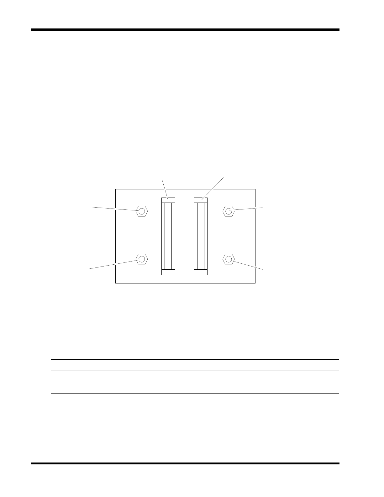
F
IGURE
1 Reference Gas
Flow Meter
Downscale
Calibration Gas
Needle Valve
Upscale
Calibration Gas
Needle Valve
Provided only if thermal conductivity cell uses flowing reference gas.
1-3. T
YPICAL GAS SELECTOR PANEL
DOWNSCALE
CAL GAS
UPSCALE
CAL GAS
REF
SAMPLE
DESCRIPTION
Sample/Calibration
Gas Flow Meter
SAMPLE
REFERENCE
Sample Gas
Needle Valve
Reference Gas
Needle Valve
NUMBER
PART
Brass and Copper construction for use with sealed reference
Stainless steel construction for use with sealed reference
Brass and Copper construction for use with flowing reference
Stainless steel construction for use with flowing reference
T
ABLE
4
1-1. A
VAILABLE GAS SELECTOR PANELS
October 2000 Rosemount Analytical 748221-KModel 7D Thermal Conductivity Analyzer
113357
113920
117195
118210
Page 17

I
NSTALLATION
2
2.1 FACILITY PREPARATION
Sections 2.1.1 through 2.1.4 provide information that may be required prior to
installation.
2.1.1 I
2.1.2 C
2.1.3 F
2.1.4 L
NSTALLATION DRAWINGS
For outline and mounting dimensions of the analyzer and gas selector panel modules,
refer to drawing 654625 and Figure 2-1or 2-2.
USTOMER ELECTRICAL CONNECTIONS
Customer electrical connections are shown in Figure 2-5.
LOW DIAGRAMS
For gas connections, refer to appropriate flow diagram:
• Analyzer using sealed reference gas, Figure 2-3
• Analyzer using flowing reference gas, Figure 2-4.
OCATION AND MOUNTING
OCATION
L
Proper location for the analyzer depends on two basic considerations:
• Accessibility to the samp ling point
• Protection of the instrument
Ideally, the analyzer should be located as close to the sampling point as possible. Short
sample lines reduce time lag in readings. In practice, however, protection of the
instrument sometimes calls for more remote placement.
The analyzer should be mounted in a clean, dry atmosphere. Ambient temperature
should be within the range of 32oF to 100 F (0oC to 38oC).
OUNTING
M
The analyzer is designed for surface mounting, utilizing the hardware provided. Refer
to drawing 654625.
748221-K Rosemount Analytical October 2000
Model 7D Thermal Conductivity Analyzer
5
Page 18

NSTALLATION
I
F
IGURE
Span Gas In
2-1. G
S
To Analyzer Zero Gas In
Sample In
8.25
[210]
Mounting Holes (4)
NO. 8 Flat Head Screw
ZERO SPAN
10.25
[260]
SAMPLE
AS SELECTOR PANEL FOR THERMAL CONDUCTIVITY CELL WITH
EALED-IN REFERENCE GAS
F
IGURE
Sample Gas
2-2. G
To Analyzer
Sample Inlet
Ref Gas
To Analyzer
Ref Gas Inlet
Upscale
Calibration Gas
Downscale
Calibration Gas
3.25
[83]
.12
[3]
1.25
[32]
CALIBRATION GAS
8.25
[210]
CALIBRATION GAS
Mounting Holes (4)
NO. 8 Flat Head Screw
10.25
[260]
DOWNSCALE
REF SAMPLE
UPSCALE
AS SELECTOR PANEL FOR THERMAL CONDUCTIVITY CELL USING
F
LOWING REFERENCE GAS
SAMPLE
REF
6
October 2000 Rosemount Analytical 748221-KModel 7D Thermal Conductivity Analyzer
Page 19

2.2 UNPACKING
The Model 7D Thermal Conductivity Analyzer is a precision instrument and should be
handled carefully. Carefully examine the shipping carton and contents for signs of
damage. Immediately notify the carrier if the carton or its contents are damaged.
Retain the carton and packing material until the instrument is operational.
NSTALLATION
I
2.2.1 G
AS REQUIREMENTS GENERAL
The Model 7D requires cylinder gases appropriate to the particular application (refer to
the Data Sheet inserted in this manual). Suitable gases are available from various
suppliers.
2.2.2 C
ALIBRATION GAS REQUIREMENTS
For calibration, the analyzer requires a downscale and an upscale calibration gas,
both normally specified in the Data Sheet. Proper choice of calibration gases for a
particular application depends on the composition of the sample stream and the
operating range used.
AMPLE GAS COMPOSITION
S
In a typical application, the sample gas consists of two components, for example:
hydrogen in nitrogen. In this example, hydrogen is designated the “measured
component” and nitrogen constitutes the “background gas.”
UPPRESSED-ZERO RANGES
S
With any zero-suppressed range, the zero-concentration point for the measured
component lies offscale, below the lower range-limit. A typical example is 80% to
100% hydrogen in nitrogen. Here the appropriate upscale calibration gas would be
pure hydrogen. The downscale gas would have a composition appropriate to
establishing a calibration point slightly above the lower range-limit e.g., 81% hydrogen
in nitrogen.
WARNING: POSSIBLE EXPLOSION HAZARD
This analyzer is of a type capable of analysis of sample gases which may be
flammable. If used for analysis of such gases, the instruments explosion-proof
enclosure must be suitable for the gas.
If explosive gases are introduced into this analyzer, the sample containment
system must be carefully leak-checked upon installation and before initial
startup, during routine maintenance and any time the integrity of the sample
containment system is broken, to ensure the system is in leak-proof condition.
Internal leaks resulting from failure to observe these precautions could result in
an explosion causing death, personal injury or property damage.
748221-K Rosemount Analytical October 2000
Model 7D Thermal Conductivity Analyzer
7
Page 20

NSTALLATION
I
2.2.3 LEAK CHECK
Pressurize the system with air or inert gas such as nitrogen, making sure not to
exceed specified pressure limitation.
Liberally cover all fittings, seals and other possible sources of leakage with leak test
liquid such as SNOOP (PN 837801).
Bubbling or foaming indicates leakage, which MUST be corrected before introduction
of flammable-sample and/or application of electrical power.
2.2.4 GAS CONNECTIONS
The analyzer and gas selector panel modules must be interconnected according to the
flow diagram specified in the Data Sheet at the front of this manual. Gas fittings on
both modules are tagged as to use. Fittings are 1/4-inch NPT for 1/4-inch (6.3 mm)
tubing. For interconnection, use 1/4-inch (6.3 mm) copper or stainless steel tubing,
depending on whether the sample stream is corrosive.
ONNECTION OF GASES
C
Refer to Figure 2-3 or 2-4 and drawing 654625. Connect sample/calibration gas lines
to fittings tagged “INLET” on bottom of analyzer. Connect appropriate vent line to
fitting labeled “OUTLET.”
Follow similar procedure for reference gas, if any.
Model 7D
Reference Gas
Sealed-In
To Vent
Sample In
Zero
Standard
Gas
Needle
Valves
113357 or 113920
Gas Selector Panel
Flowmeter
Thermal Conductivity Analyzer
Thermal Conductivity Cell
F
IGURE
8
Span
Standard
Gas
2-3. C
A
ONNECTION OF ANALYZER USING SEALED-IN REFERENCE GAS TO
SSOCIATED GAS
October 2000 Rosemount Analytical 748221-KModel 7D Thermal Conductivity Analyzer
Page 21

A. DIFFERENT REFERENCE GAS AND CALIBRATION GAS
NSTALLATION
I
Reference
Gas
Sample Gas
Downscale
Calibration
Gas
Upscale
Calibration
Gas
Needle
Valves
117195 or 118210
Gas Selector Panel
Reference
Gas
Flowmeter
Sample
Gas
Flowmeter
B. REFERENCE GAS ALSO USED AS CALIBRATION GAS
Downscale
Calibration Gas
Used as
Needle
Valves
117195 or 118210
Gas Selector Panel
Thermal Conductivity Analyzer
Thermal Conductivity Cell
Thermal Conductivity Analyzer
Model 7D
Model 7D
To
Sample
Vent
To
Reference
Vent
Sample Gas
Downscale
Calibration
Gas
Upscale
Calibration
Gas
F
IGURE
2-4. C
A
ONNECTION OF ANALYZER USING FLOWING REFERENCE GAS TO
SSOCIATED GAS SELECTOR PANEL
748221-K Rosemount Analytical October 2000
Reference
Gas
Flowmeter
Sample
Gas
Flowmeter
Thermal Conductivity Cell
To
Reference
Sample
Vent
Vent
Model 7D Thermal Conductivity Analyzer
To
9
Page 22

NSTALLATION
I
OPTIONAL DUAL ALARMS
11
10
13
14
15
17
19
TB10
12
16
18
DETECTOR ASSEMBLY
9
8
7
6
5
4
2
3
20
1
TEMPERATURE CONTROL
Heater
ASSEMBLY
Fan
RECORDER VOLTAGE
OUTPUT AND CURRENT
OUTPUT
TB4
4
(-) CURRENT
3
(+) CURRENT
2
(-) VOLTAGE
(+) VOLTAGE
1
IGURE
F
2-5. E
CAUTION
AC POWER INPUT
Fuse
TB6
1 2 3
L1 L2 GND
LECTRICAL CONNECTIONS
DC POWER SUPPLIES
MASTER
BOARD
Do not plug or restrict vents.
2.3 RECORDER OUTPUT SELECTION AND CABLE
CONNECTIONS
If a recorder, controller, or other output device is used, connect it to the analyzer (refer
to drawing 654642) via a number 22 or number 24 AWG two-conductor shielded
cable. Route the cable through conduit to the analyzer, and into the case through the
appropriate opening shown in drawing 654625.
10
October 2000 Rosemount Analytical 748221-KModel 7D Thermal Conductivity Analyzer
Page 23

NSTALLATION
I
Note:
Route recorder cable through a separate conduit, not with power cable.
Output selection and cable connections for voltage-actuated and current-actuated
devices are explained in Sections 2.3.1 through 2.3.5.
2.3.1 S
TANDA RD (NON-LINEARIZED
OLTAGE OUTPUT
) V
1. On the Master Board (Figure 2-6):
a. Verify that TB2-1 is jumpered to TB2-2.
b. Set S1 for desired voltage: 5V, 1V, .1V, or .01V.
c. Connect the recorder cable to the TB4 terminals labeled VOLT OUT: TB4-1(+)
and TB4-2(-).
Note
Take the usual precautions to avoid AC pickup. DO NOT GROUND EITHER
LEAD.
2. Connect the cable to input terminals of the recorder; ensure that polarity is correct.
3. Ground shield on one end only.
2.3.2 L
INEARIZED VOLTAGE OUTPUT (OPTIONAL
)
1. Verify that Voltage-Output Linearizer Board (PN 633756) is properly inserted in
J102.
2. On the Master Board (Figure 2-6):
a. Verify that TB2-1 is jumpered to TB2-4, and TB2-2 is jumped to TB2-5.
b. Set S1 for desired voltage: 5V, 1V, .1 V, or .01 V.
c. Connect the recorder cable to the TB4 terminals labeled VOLT OUT: TB4-1 (+)
and TB4-2 (-).
Note
Take the usual precautions to avoid AC pickup. DO NOT GROUND EITHER
LEAD.
3. Connect the cable to the recorder input terminals; ensure that polarity is correct.
2.3.3 I
SOLATED 4 TO
20 MA C
URRENT OUTPUT (OPTIONAL
)
1. Verify that the Isolated 4 to 20 mA Current Output Board (PN 652816) is properly
inserted in J103.
2. On the Master Board (Figure 2-6):
a. Verify that TB2-1 is jumpered to TB2-2 and TB2-2 is jumpered to TB2-6.
748221-K Rosemount Analytical October 2000
Model 7D Thermal Conductivity Analyzer
11
Page 24

NSTALLATION
A
A
A
I
b. Connect the recorder cable to the TB4 terminals labeled CUR OUT : TB4-3 (+)
and TB4-4 (-).
3. Connect the cable to the recorder input terminals; ensure that polarity is correct.
Total resistance of the output device and associated cable must not exceed 1500
ohms.
- + - +
CUR
VOLT
OUT
J4
C
POWER
HEATER
POWER
FAN
115V 230V
OUT
1
1
R4 R9 R7R22 R26 R6 R8
TB4
R15
C2
F13
1
R12
R10
C4
R14
R19R21 R18
J2
J7
J6
1
S2
R2
AR1
R11
R17R20
S1
R24
R16
6 5 4 3 2 1
BOARD
OPTIONS
U1
RESISTOR
SELECT
R27
RANGE
R1
R5
C3
C1
SPAN
R3
R2
METER
C5
C6
R23
R3
C7
TB2
TP1 TP2
1
2
3
4
TB5
1
2
3
4
5
6
7
8
TB3
11
J101 J100
TP3 TP4 TP5
1
J103 J102
1
TB1
6 5 4 3 2 1
DETECTOR
R100
S1
Used to select voltage output range: 5V, 1V, 0.1V, or
.01V
AR1 gain adjust. Permits adjustment of AR1 gain from
R4
X1 to X100, to establish the sensitivity desired for
Range 1. This is the highest sensitivity range.
R6, R8, R26
R9
.01V .1V 1V 5V
R7
R22
DETAIL OF S1
R15
R16
IGURE
F
2-6. M
ASTER BOARD
12
AR1 zero adjust. Used to eliminate voltage offset
within AR1 and Bridge, and provide zero suppression.
Setting determines attenuation factor applicable to AR2
output, Range 3.
Setting determines attenuation factor applicable to AR2
output Range 2.
Permits adjusting meter fullscale to agree with recorder
fullscale
Used to eliminate voltage offset within AR2.
Sets the stable ±10 V source.
ADJUSTMENTS
October 2000 Rosemount Analytical 748221-KModel 7D Thermal Conductivity Analyzer
Page 25

NSTALLATION
I
2.3.4 D
UAL ALARMS (OPTIONAL
)
The alarm module is installed in the instrument as shown in Figure 1-2 and electrical
connections are shown in drawi ng 654642. The analyzer is factory configured and requires no
user adjustments.
Pins for AC power (1, 2, and 3), alarm setpoint control (8, 10, 18, and 19), and signal from
analyzer circuitry (7 and 9) are wired at the factory. Connections of the remaining pins
depend on individual applicati on requir ements.
If the instrument has this option, the analyzer will have the following setpoint adjustment
potentiometers: Alarm 1 (the Low Alarm) and Alarm 2 (the High Alarm) on the front panel
(Figure 1-1) and Deadband on the al arm module (see Fi gure 2-7) .
FRONT VIEW OF ALARM MODULE
Deadband Potentiometer
ALARM 1
LED Indicator
ALARM 1
Deadband
ZERO
Deadband Potentiometer
ALARM 2
Deadband
F
IGURE
2-7. A
LED Indicator
ALARM 2
LARM ADJUSTMENTS
SPAN
The power and input signals have been wired to the terminal strip into which the alarm
module plugs. The wiring to the contacts (18 or 20 AWG) is routed through a conduit hole
(see Drawing 654625) .
The alarm relay is in energiz ed mode when power is applied. Wire output to the appropriate
contact (see Figure 2-5 and Table 2-1). The Form C relay contacts are rated at 5 A, 120
VDC and 1 A, 120 VAC, resistive loads.
A lit LED next to the Deadband pots indicates the alar m is activ ated.
748221-K Rosemount Analytical October 2000
Model 7D Thermal Conductivity Analyzer
13
Page 26

NSTALLATION
I
PIN OUTPUT PIN OUTPUT
11 N.C. #1 14 N.O. #2
12 COM #1 15 COM #2
13 N.O. #1 1 6 N.C. #2
Contact Rating: 1.0 A, 120 VAC; 5.0 A, 120 VAC. Form C, resistive loads.
T
ABLE
2-1. A
LARM OUTPUT CONNECTIONS
Note:
The Zero and Span for setting the input voltage from the analyzer has been set
at the factory. To check it, see Section 6.2.5.
The following is recommended:
1. A fuse should be inserted into the line between the customer-supplied power
supply and the alarm module terminals on the Alarm Relay Assembly.
2. If the alarm contacts are connected to any device that produces radio frequency
interference (RFI), the device should be arc-suppressed (P/N 858728 Arc
Suppressor is recommended).
3. The analyzer and any RFI-producing device should operate on different AC power
sources to avoid RFI.
Removal of AC power from the analyzer, as in a power failure, de-energizes both
alarm module relays, setting an alarm condition. Switching characteristics of the
ALARM 1 and ALARM 2 relays are as follows:
LARM
A
1 R
ELAY
The ALARM 1 relay coil is de-energized when the meter needle moves downscale
through the value that corresponds to setpoint minus deadband. This relay coil is
energized when the needle moves upscale through the value that corresponds to
setpoint plus deadband (see Figure 2-8).
LARM
A
2 R
ELAY
The ALARM 2 relay coil is de-energized when the meter needle moves upscale
through the value that corresponds to the setpoint plus deadband. This relay coil is
energized when the needle moves downscale through the value that corresponds to
setpoint minus deadband (see Figure 2-8).
AIL-SAFE APPLICATIONS
F
By making the appropriate connections to the double-throw relay contacts, the
operator can obtain either 1) a contact closure or contact opening for an energized
relay, or 2) a contact closure or contact opening for a de-energized relay. For fail-safe
applications, the operator must understand which circuit conditions are required to
achieve relay de-energization in the event of power failure.
14
October 2000 Rosemount Analytical 748221-KModel 7D Thermal Conductivity Analyzer
Page 27

NSTALLATION
I
2.3.5 L
INEARIZED VOLTAGE
WO RANGES (OPTIONAL
, T
)
1. Verify that the Voltage Output Linearizer Board (PN 633756) is properly inserted in
both J102 and J103.
2. Verify that the range switch on the door is properly connected: Position (Range) 1
to TB2-5, Position 2 to TB2-3, Wiper to TB2-2.
3. On the Master Board (Figure 2-6):
a. Verify that TB2-1 is jumpered to TB2-4, and TB2-4 is jumped to TB2-6.
b. Select desired range on S1.
c. Connect recorder cable to the TB4 terminals labeled VOLT OUT: TB4-1 (+) and
TB4-2 (-).
Note
Take the usual precautions to avoid AC pickup. DO NOT GROUND EITHER
LEAD.
4. Connect the cable to the recorder input terminals; ensure that polarity is correct.
A. Typical ALARM 1 Setting (LOW)
F
IGURE
DEADBAND SET FOR
20% OF FULLSCALE
B. Typical ALARM 2 Setting (HIGH)
DEADBAND SET FOR
10% OF FULLSCALE
2-8. T
YPICAL ALARM SETTINGS
INPUT SIGNAL
Percent of Fullscale
INPUT SIGNAL
Percent of Fullscale
When input signal moves upscale through this point, the
40
30
20
55
50
45
coil of ALARM 1 relay (K1) is energized, providing
continuity between the common and normally-closed
contacts of the relay.
ALARM 1 Setpoint
When input signal moves downscale through this point, the
coil of ALARM 1 relay (K1) is de-energized, providing
continuity between the common and normally-open
contacts of the relay.
When input signal moves upscale through this point, the
coil of ALARM 2 relay (K2) is de-energized, providing
continuity between the common and normally-open
contacts of the relay.
ALARM 2 Setpoint
When input signal moves upscale through this point, the
coil of ALARM 2 relay (K2) is energized, providing
continuity between the common and normally-closed
contacts of the relay.
748221-K Rosemount Analytical October 2000
Model 7D Thermal Conductivity Analyzer
15
Page 28

NSTALLATION
I
2.3.6 L
INEARIZED VOLTAGE AND ISOLATED 4 TO
PTIONAL
(O
)
20 MA C
URRENT OUTPUT
1. Verify that the Voltage Output Linearizer Board (PN 633756) is properly inserted in
J102.
2. Verify that the Isolated 4 to 20 mA Current Output Board (PN 652816) is properly
inserted in J103.
3. On the Master Board (Figure 2-6):
a. Verify that TB2-1 is jumped to TB2-4, TB2-2 is jumped to TB2-5, and TB2-5 is
jumped to TB2-6.
b. Set S1 for the desired voltage: 5 V, 1 V, .1 V, or .01 V.
c. Connect the recorder cable to the TB4 terminals labeled VOLT OUT: TB4-1 (+)
and TB4-2 (-).
Note
Take the usual precautions to avoid AC pickup. DO NOT GROUND EITHER
LEAD.
4. Connect the cable to recorder VOLTAGE input terminals; ensure that polarity is
correct.
5. On the Master Board (Figure 2-6):
a. Connect the recorder cable to the TB4 terminals labeled CUR OUT : TB4-3 (+)
and TB4-4 (-).
6. Connect the cable to the recorder CURRENT input term inals; ensure that polarity
is correct.
2.4 ELECTRICAL POWER CONNECTIONS
WARNING: ELECTRICAL SHOCK HAZARD
For safety and proper performance, this instrument must be connected to a
properly grounded three-wire source of power.
Note
Before supplying electrical power to analyzer, disconnect the red lead from the
bridge to TB1-1 or TB1-2 (depending on bridge polarity). This action
disconnects power to the bridge (see drawing 654642). To safeguard against
filament damage, this lead should remain disconnected until proper gas flow
has been established.
16
October 2000 Rosemount Analytical 748221-KModel 7D Thermal Conductivity Analyzer
Page 29

NSTALLATION
I
The analyzer is supplied, as ordered, for operation on 107 to 127 or 214 to 254 VAC,
50/60 Hz, 250 watts. Verify that the power source conforms to the requirements of the
individual instrument as noted on the name rating plate. Ensure that switches S2 on
the Master Board (see Figure 2-6) and S3 on the case heater temperature control
board (see Figure 2-9) are set to required voltage.
Electrical power is supplied to the analyzer via a customer-supplied three-conductor
cable, type SJT, minimum wire size 18 AWG. Route the power cable through conduit
and into the appropriate opening in the instrument case (see drawing 654625). On
TB6, Figure 2-5, connect cable leads to terminals 1 (HOT/L1), 2 (NEUT/L2), and 3
(GND).
Set switch window for voltage required
S3
F
IGURE
2-9. C
R10 R11 R7 R8
C2
CR1
C
B
Q2
SENSOR J18
400A 880 951E
R17 R16 R12CR
R4
R3
C1
E
+
TEMP CONTROL BD
1
AR1
R13
R2R1
Q1
K
G
A
POWER
SUPPLY
R6
C3
R9 R5
CR
1
E
B
Q3
C
TEST
J19
J11
R15
POWER
LINE
J5
C4
3 2 1
R14
1
1 2 1 2 3
T.I.F. HEATER
U2
2
3
1
U1
J17
ASE HEATER TEMPERATURE CONTROL BOARD
S3
230
115
115
748221-K Rosemount Analytical October 2000
Model 7D Thermal Conductivity Analyzer
17
Page 30

NSTALLATION
I
N
OTES
18
October 2000 Rosemount Analytical 748221-KModel 7D Thermal Conductivity Analyzer
Page 31

I
NITIAL STARTUP
3
3.1 ANALYZER CONTROLS AND ADJUSTMENTS
Normal operation of the analyzer involves adjustments of only the front-panel controls:
ZERO and SPAN, and RANGE Switch, if provided. See Figure 1-1.
The various internal adjustments are factory set and normally do not require
readjustment except after replacement of a circuit board or major component. Refer
to Section 6, Service and Maintenance.
3.2 GAS SELECTOR PANEL CONTROLS
The controls provided on the optional gas selector panel will depend on the
application. For use of sealed-in reference gas, refer to Figures 2-1 and 2-3. For
flowing reference gas, refer to figures 2-2 and 2-4.
3.3 STARTUP PROCEDURE
WARNING: POSSIBLE EXPLOSION HAZARD
If explosive gases are introduced into this analyzer, the sample containment
system must be carefully leak-checked upon installation and before initial
startup, during routine maintenance and any time the integrity of the sample
containment system is broken, to ensure the system is in leak-proof condition.
Leak-check instructions are provided in Section 2.2.3.
Internal leaks resulting from failure to observe these precautions could result in
an explosion causing death, personal injury or property damage.
Note:
Never apply power to analyzer without gas flowing. The filaments in the cell
tend to deteriorate faster than normal.
748221-K Rosemount Analytical October 2000
Model 7D Thermal Conductivity Analyzer
19
Page 32

NITIAL STARTUP
I
Note:
Before supplying electrical power to the analyzer, disconnect the red lead from
the bridge to TB1-1 or TB1-2 on the Master Board (depending on detector bridge
polarity). This action disconnects power to the bridge. To safeguard against
filament damage, this lead should remain disconnected until proper gas flow
has been established. Refer to drawing 654642.
After performing a leak check, start up the analyzer as follows:
1. Remove the connector from J2 on the Master Board (Figure 2-6). Verify that this
line goes to TB6, located at the lower left of the instrument (see Figure 1-2). If it
does not, make corrections using drawing 654642 as a reference.
2. Set regulators on the gas cylinders for a supply pressure of 10 to 50 psig f(69 to
345 kPa).
3. Provide a sample flow of 50 to 350 cc/minute through the analyzer. A rate of 250
cc/minute is recommended unless faster flow is desired to reduce sample transport
time.
4. If the thermal conductivity cell uses flowing reference gas, provide a reference flow
of 5 to 50 cc/minute.
5. Refer to drawing 654642 and Figure 2-6. Connect the cable from TB6 to J2 on
the Master Board to provide AC power to the Master Board. Reconnect the red
lead of TB1 (or TB2) to provide power to the detector. Apply power to the
analyzer. The filaments will now begin to heat. Verify proper flow of sample gas
and flowing reference gas, if used.
6. Allow the analyzer to warm-up for a minimum of six hours to ensure temperature
equilibrium.
Note:
If ambient temperature is below 60
60
°°°°
F (15.6
°°°°
C) within the next six hours, allow a minimum of 12 hours for the
°°°°
F (15.6
°°°°
C), or if the temperature will go below
instrument to stabilize.
Startup is now complete; the analyzer is ready for calibration per Section 3.4.
20
October 2000 Rosemount Analytical 748221-KModel 7D Thermal Conductivity Analyzer
Page 33

3.4 CALIBRATION
1. Set downscale calibration point as follows:
a. On the analyzer, set front-panel SPAN control to midscale (five turns). If the
analyzer has front-panel RANGE Switch, set it at Range 1, the highest
sensitivity range.
b. Admit downscale calibration gas to the analyzer at the same flow rate as is
used for sample gas. Wait for the reading on the meter or recorder to stabilize.
c. On the analyzer, adjust the front panel ZERO control so that the reading on the
front panel meter or recorder is appropriate to the downscale calibration gas.
d. If a proper reading is unobtainable by adjustment of the ZERO control, refer to
Section 6.2.2.
2. Set upscale calibration point as follows:
a. If the analyzer has a front panel RANGE switch, set it for the desired range.
b. Admit upscale calibration gas to the analyzer at the same flow rate as is used
for sample gas. Wait for the reading on the meter or recorder to stabilize.
NITIAL STARTUP
I
c. On the analyzer, adjust the front panel SPAN control so that the reading on the
front panel meter or recorder is appropriate to the upscale calibration gas.
If a proper reading is unobtainable by adjustment of the SPAN control, refer to Section
6, Service and Maintenance.
After the downscale and upscale calibration points have been established, the
analyzer is ready for routine operation per Section 4.
If the analyzer has Suppressed-Zero Ranges and does not calibrate properly, refer to
Section 6.3 for Suppressed Zero Adjustment.
748221-K Rosemount Analytical October 2000
Model 7D Thermal Conductivity Analyzer
21
Page 34

NITIAL STARTUP
I
NOTES
22
October 2000 Rosemount Analytical 748221-KModel 7D Thermal Conductivity Analyzer
Page 35

O
PERATION
4
4.1 ROUTINE OPERATION
First, complete startup per Section Three. If the analyzer has more than one range,
turn front panel RANGE Switch to desired position. Admit sample gas at the
previously selected flow rate. The analyzer will continuously indicate the
concentration of the measured component in the sample stream.
A calibration curve can be used to convert meter or recorder readings to concentration
values. Typical calibration curves are supplied for standard ranges. Calibration
curves for special ranges are available as options.
To avoid use of a calibration curve in an application where it would otherwise be
required, the analyzer may be equipped with an optional linearizer board. If so, the
linearizer board is factory set for a given range only, and is not usable on another
range. Note that a linearizer is usable only if nonlinearity at midscale does not exceed
20% of fullscale.
4.2 RECOMMENDED CALIBRATION FREQUENCY
Provided that the instrument remains in continuous operation with power on, it is
necessary only to calibrate once a week, by the procedure of Section 3.4.
To restart the analyzer after power turn-off, repeat the startup procedure of Section
3.3 and calibrate per Section 3.4.
4.3 SHUTDOWN
Before turning off sample gas, and flowing reference gas, if used, disconnect power
from the analyzer. This precaution minimizes the risk of filament damage.
748221-K Rosemount Analytical October 2000
Model 7D Thermal Conductivity Analyzer
23
Page 36

PERATION
O
NOTES
24
October 2000 Rosemount Analytical 748221-KModel 7D Thermal Conductivity Analyzer
Page 37

T
HEORY
5
5.1 THERMAL CONDUCTIVITY CELL AND ASSOCIATED
BRIDGE ADJUSTMENTS
Within the thermal conductivity cell are four resistive filaments suspended in individual
cavities of a metal block (Figure 5-1A) and connected electrically as legs of a
Wheatstone bridge (Figure 5-1B). Although physically the cell block is one piece,
functionally it may be considered to have two sides as shown in Figure 5-1B:
AMPLE SIDE
S
Two filaments that constitute opposite legs of the bridge are positioned in a passage
that receives a continuous flow of the sample gas.
EFERENCE SIDE
R
The remaining two filaments are positioned in a passage filled with the reference gas.
Depending on the application, the reference gas may flow continuously through the
passage, or it may be sealed within the cell.
The Bridge Voltage Power Supply (PN 613560) is connected, via a 20-ohm dropping
resistor, to the bridge (See section 5.2.4). The power supply output is adjusted to
provide an appropriate voltage across bridge terminals 1(+) and 2(-). An electric
current flows through the filaments, heating them and thus increasing their electrical
resistance. The heat-dissipation rate for each filament depends on the thermal
conductivity of the surrounding gas. Initially, with downscale calibration gas flowing
through the sample and reference sides of the flow-through configuration, R26 is set
for zero bridge-output signal. During subsequent analysis of the sample stream, any
change in the relative proportions of the components passing through the sample side
changes the thermal conductivity of the gas mixture, causing a temperature differential
between sample and reference filaments. The resultant change in filament resistance
unbalances the bridge.
The bridge-imbalance signal is routed to the Master Board (PN 654620), where it is
processed to drive the front-panel meter and recording device, if used (see Section
5.2.1).
Periodically, downscale calibration gas is passed through the cell, and the front panel
ZERO Pot is adjusted for an appropriate reading on the meter or recorder.
748221-K Rosemount Analytical October 2000
Model 7D Thermal Conductivity Analyzer
25
Page 38

HEORY
T
5.2 ELECTRONIC CIRCUITRY
Electronic circuitry of the Model 7D is shown in the schematic diagram of drawing
654616. Internal circuitry of plug-in boards and other electronic assemblies is shown
in separate schematic diagrams, found at the end of this manual, and is described in
the following sections.
5.2.1 M
ASTER BOARD
The Master Board (PN 654620), Figure 2-6, provides two stages of amplification
utilizing integrated-circuit amplifiers AR1 and AR2.
UNCTIONS ASSOCIATED WITH
F
AR1
AR1
Gain Adjust Potentiometer R4. This screwdriver-adjustable, factory-set trimming
potentiometer determines feedback resistance for AR1 and thus permits adjustment of
AR1 gain from X1 to X100. This adjustment sets the sensitivity for Range 1, i.e., the
highest-sensitivity range.
R
ANGE PROVISIONS
In the basic single-range Model 7D, a jumper is connected from TB3-1 to TB3-4, thus
routing the unattenuated output from AR1 directly to the non-inverting input of AR2.
During factory assembly of a dual-range or triple-range instrument, the jumper is
omitted and a front panel RANGE Switch is connected as shown below. The output
from AR1 is then routed to AR2 through a network that provides adjustable
attenuation for ranges 2 and 3.
T
ABLE
26
RANGE
1X1, fixed 1 1
2 adjustable by R7 2 2
3 adjustable by R9 3 3
5-1. R
OARSE ZERO AND ZERO-SUPPRESSION
C
Pots R26, R6 or R8, depending upon range number, provide the zero correction at the
non-inverting input of AR1.
ANGE SWITCH CONNECTIONS
AR1 OUTPUT
ATTENUATION
RANGE SWITCH
POSITION
wiper 4
October 2000 Rosemount Analytical 748221-KModel 7D Thermal Conductivity Analyzer
TB3 POSITION
Page 39

ECTIONAL VIEW OF THERMAL CONDUCTIVITY CELL
A. S
Thermal Conductivity
Cell Block
Sample
Gas Out
HEORY
T
Reference
Filaments
Reference *
Gas In
Sample Gas In
* Reference Ports Capped if Cell
Uses Sealed-In, Non-Flowing Reference Gas.
UNCTIONAL DIAGRAM OF BRIDGE CIRCUIT
B. F
3
0.5
Front Panel Zero
Potentiometer
4
O-Ring
Seals
Sample Filaments
NOTE: Cell Block Sectioned
Through Sample Side.
Section Through
Reference side is
Similar.
6
0.5
7
Reference Flow
1
Resistor values are in ohms.
F
IGURE
748221-K Rosemount Analytical October 2000
5-1. T
HERMAL CONDUCTIVITY CELL
0.5 20
5
Bridge Power
Supply (+)
2
0.5
Sample Flow
Bridge Power
Supply (-)
Model 7D Thermal Conductivity Analyzer
8
27
Page 40

HEORY
T
UNCTIONS ASSOCIATED WITH
F
AR2
AR2 Z
This screwdriver-adjustable, factory-set trimming potentiometer is used to eliminate
voltage offset within AR2. When the input signal is zero, R15 is adjusted so that the
output signal also is zero.
F
RONT-PANEL
This potentiometer, connected across TB3-5 and TB3-6, provides continuously
variable adjustment of closed-loop gain for AR2, to permit establishing an upscale
calibration point on the meter scale or recorder chart. With upscale calibration gas
flowing through the analyzer, the SPAN Control is adjusted for the appropriate
reading.
F
RONT-PANEL METER
The meter is connected from TB3-7 to TB3-8. Potentiometer R22 permits adjusting
meter sensitivity so that meter fullsca le agrees with recorder fullscale.
O
The desired output is obtained by appropriate selection of switch contacts: 5V, 1V,
.1V, or .01V.
ERO ADJUSTMENT POTENTIOMETER
SPAN C
UTPUT SELECTION SWITCH
ONTROL
S1
R1
5.2.2 V
5.2.3 I
OLTAGE OUTPUT LINEARIZER BOARD (OPTIONAL
The output signal from the Master Board is a function of the degree of imbalance in
the bridge circuit, but is not linear with respect to the concentration of the measured
component. Providing that the nonlinearity of the calibration curve does not exceed
20% at midscale (for 50 % H2 max.), the Voltage Output Linearizer Board (PN
633756) may be used to equip a given operating range for linear readout of
concentration on the meter and on a potentiometric recorder.
Straightening of the concentration-vs.-output curve is accomplished by sequential
adjustment of eight odd-numbered trimming potentiometers designated R19 through
R33. Each pot controls the gain of an associated operational amplifier.
During factory checkout of a linearizer circuit board, potentiometers R19 through R33
are initially set at midrange. With zero input signal applied to the linearizer circuit,
ZERO potentiometer R35 is adjusted for zero output. Then an appropriate low-level
signal is applied to the input, and R19 is adjusted for fullscale output. The procedure
is repeated as many times as required to obtain properly linearized output.
SOLATED 4 TO
This option provides isolated current output for applications which require 4 to 20 mA
into a maximum load of 1500 ohms. This output is NOT linearized. A description of
20 MA C
URRENT OUTPUT BOARD (OPTIONAL
)
)
28
October 2000 Rosemount Analytical 748221-KModel 7D Thermal Conductivity Analyzer
Page 41

HEORY
T
the board and the functions of its main components follows. Refer to schematic
652813 at the rear of this manual.
The purpose of the Isolated Current-Output Board (PN 625816) is to convert an input
signal of 0 to -5 V to an isolated output signal of 4 to 20 mA. With a zero voltage at
the input, R6 is adjusted so that the output at AR1 is 1 V. The gain of AR1 is .8 so
that an input of 0 to -5 V is converted to 1 to 5 V. This voltage is fed to a variable
output level-inverter consisting of AR2, Q1, Q2, and T1. T1 has two identical output
windings, each with a rectified DC output. One is used to provide feedback to the
inverter input of AR2. The other is used as an isolated output to drive AR3 and Q3
with a 1 to 5 V signal across R16. Trim-pot R17 is adjusted to provide a span of 4 to
20 mA. This current is presented to the collector of Q3 and is capable of driving loads
of up to 1500 ohms.
5.2.4 B
RIDGE POWER SUPPLY
The regulated, adjustable voltage required for the thermal conductivity bridge (Section
5.1) is provided by the Bridge Power Supply (PN 613560). It consists of a power
transformer, fullwave rectifiers CR1 and CR2, voltage regulator Q1, and an RC filter
network. Bridge voltage, as measured between bridge terminals 1(+) and 2(-), is
adjustable from 5 to 13 VDC via R2. Proper setting depends primarily on filament
material: 3 to 4 VDC for tungsten; 5 to 12 VDC for Hitempco. Bridge voltage is
factory-set as required for the application (see Data Sheet) and normally does not
require readjustment unless the power supply is replaced.
5.2.5 ±15 V
OLT POWER SUPPLY
The ±15 Volt Power Supply (PN 619714) plugged into J101 of the Master Board,
provides power for the various circuits. As shown in drawing 619710, power
transformer T1 has three secondary that are used as follows:
38 VAC
CENTER-TAPPED SECONDARY
Powers both 15 volt supplies thr ough diode bri dge CR1 and filter capaci tors C1 and C4.
The adjustable positive regulator, VR1, is set by voltage divider R1, R2 and R3 and its
output is applied to pin A of the circuit board and to test point TP1. Potentiometer R2
should be adjusted to +15.5 VDC ±50 mVDC.
The negative DC, regulated by VR2 is applied to pin D of the circuit board.
The center tap is the common reference for both the +15 and -15 volt supplies and is
applied to pin R of the circuit board and to test point TP2.
Both outputs are used for individual amplifiers on the various circuit boards.
VOLT CENTER-TAPPED SECONDARY
90-
Drives a rectifier circuit on the optional Current Output Board (PN 652816). The
748221-K Rosemount Analytical October 2000
Model 7D Thermal Conductivity Analyzer
29
Page 42

HEORY
T
transformer winding and the associated circuit constitute a floating power supply for
the emitter-follower stage. Refer to Section 5.2.3.
9.5 VAC
SECONDARY
Drives a +5 VDC supply not used in this instrument.
5.2.6 D
ETECTOR BLOCKS
There are two types of detector configurations; flowing reference and sealed nitrogen
reference. The sealed reference with nitrogen can be recharged by flowing nitrogen
through the reference and closing the plugs. Three filament types are available:
tungsten, Hitempco, and gold-sheathed tungsten.
5.2.7 C
ASE TEMPERATURE CONTROLLER ASSEMBLY
The case Temperature Controller Assembly (PN 652270) maintains an approximate
117°F (47°C) temperature within the instrument.
Changes in case temperature affect the resistance of the sensor connected to J18.
This in turn changes the bias of amplifier AR1, which controls the input to the case
heater via switch U2. The heater receives power through pins 3, 4 and/or 5,
depending on the voltage selected at switch S3. A thermal fuse at J5 prevents the
case from overheating.
5.2.8 D
UAL ALARMS (OPTION
)
Instruments with optional Dual Alarms have two pots on the front door which are used
to select setpoints. The scales on the nameplate designate setpoints from 0 to 100%.
The alarm module is shown in Figure 7-2, and the factory connections are shown in
drawing 654642. The module plugs into a socket, which is part of a terminal block
mounted onto the chassis of the instrument. A marker on the alarm module indicates
the function of each socket pin.
This unit is factory configured and requires no user adjustment. Pins for AC power (1,
2, and 3), alarm setpoint control (8, 10, 18, and 19), and signal from analyzer circuitry
(7 and 9) are wired at the factory.
Connections of the remaining pins depend upon the application. The relays are rated
at 1.0 A, 120 VAC and 5.0 A, 120 VDC, form C, resistive loads.
30
October 2000 Rosemount Analytical 748221-KModel 7D Thermal Conductivity Analyzer
Page 43

S
ERVICE AND
M
AINTENANCE
6
WARNING: POSSIBLE EXPLOSION HAZARD
If explosive gases are introduced into this analyzer, the sample containment
system must be carefully leak-checked upon installation and before initial
startup, during routine maintenance and any time the integrity of the sample
containment system is broken, to ensure the system is in leak-proof condition.
Leak-check instructions are provided in Section 2.2.3.
Internal leaks resulting from failure to observe these precautions could result in
an explosion causing death, personal injury or property damage.
In troubleshooting, the basic approach is to isolate the analyzer from the sample and
the sample-handling system.
First admit downscale and upscale standard gases to analyzer and note response:
1. If performance is normal with standard gases, although not with sample gas, the
sample and the sample-handling system are suspect. Check these areas.
2. If analyzer gives offscale or erratic readings with standard gases, as well as with
sample gas, the problem might be the filaments or the electronic circuitry. To
isolate the malfunction, substitute fixed precision resistors of appropriate value for
the filaments. Hitempco filaments (P/N 25499) have a cold resistance of 72 ohms.
Tungsten filaments (P/N 811993) have a cold resistance of 18 ohms. Filament
connections are shown in drawing 654616. W ith appropriate resistors substituted
for the filaments, attempt to balance the bridge as follows:
a. If bridge balance is obtained with the fixed resistors, the filaments are probably
defective and should be replaced.
b. If bridge balance is unobtainable with the fixed resistors, the problem might be
the electronic circuitry. Substitute each circuit board, in turn, until proper
operation is obtained.
748221-K Rosemount Analytical October 2000
Model 7D Thermal Conductivity Analyzer
31
Page 44

ERVICE AND MAINTENANCE
S
6.1 THERMAL CONDUCTIVITY CELL
The thermal conductivity cell and associated elements of the bridge are mounted
inside the analyzer case, within a thermally-insulated compartment.
Depending on the bridge current level, the filaments gradually become mismatched,
and eventually burn out. Normal progression of symptoms is baseline drift. Sealed
reference cells must be serviced by the factory.
If the cell uses flowing reference gas, the filaments may be replaced by the user.
Refer to Figure 5-1 and the parts list in Section 7.
Filaments are sold as matched sets. If one must be replaced, its mate also must be
replaced. Electrically, the filaments are mated across the diagonals of the cell. Refer
to Figure 5-1B. The filament across points 3 and 1 corresponds to the filament across
8 and 1, and the filament across points 6 and 2 corresponds to the filament across 5
and 2.
6.2 ELECTRONIC CIRCUITRY
6.2.1 A
6.2.2 B
MPLIFIER ZERO ADJUSTMENTS
The zero adjustments on the Master Board are factory set and normally do not require
readjustment except after replacement of a major component. If readjustment
becomes necessary, use following procedure:
AR2 Z
1. Open the input to AR2. In a single-range instrument, this is done by disconnecting
2. Ground the input of AR2 by connecting a jumper from TB3-4 to TP1 (GND).
3. Adjust R15, Figure 5-2, for 0 VDC output signal at TB4-2.
4. Restore connections to normal.
Perform start-up procedure in Section 3.3, then proceed as follows:
1. On the analyzer module, set the front panel ZERO and SPAN potentiometers to
ERO ADJUSTMENT
the jumper from TB3-1 to TB3-4.
RIDGE BALANCE AND RANGE SENSITIVITY ADJUSTMENTS
their midpoints (five turns). If the analyzer has a front panel RANGE Switch, set it
to Range 1, the highest-sensitivity range.
:
32
2. Admit downscale calibration gas to the analyzer at the same flow rate as is used
for the sample gas. Wait for the reading on the meter or recorder to stabilize.
October 2000 Rosemount Analytical 748221-KModel 7D Thermal Conductivity Analyzer
Page 45

ERVICE AND MAINTENANCE
S
3. Refer to Figure 2-6 and set the Balance Adjustment on the Master Board, (range 1
or single range R8, range 2 R6, range 3 R26) so that the reading on the meter or
recorder is zero or an offset value. Refer to Data Sheet.
ENSITIVITY ADJUSTMENT(S) ARE
S
:
1. Admit upscale calibration gas to the analyzer at the same flow rate as is used for
the sample gas. Wait for reading on meter or recorder to stabilize.
2. On the Master Board, set AR2 Gain Adjustment R4 so that reading on the
recorder, if used, or on the front-panel meter is appropriate to the upscale
calibration gas. Refer to data sheet or calibration curve. Range 1 sensitivity is
now properly adjusted.
3. If analyzer has more than one range, set the front panel RANGE Switch for Range
2. This is the reduced sensitivity range. Then, on the Master Board, set Range 2
Attenuation Adjustment R7 so that the reading on the recorder, if used, or on the
front panel meter is appropriate to the upscale calibration gas.
4. If the analyzer has three ranges, set the front panel RANGE Switch for Range 3.
This is the least sensitive range. Then, on the Master Board, set Range 3
Attenuation Adjustment R9 so that the reading on the recorder, if used, or on the
front panel meter is appropriate to the upscale calibration gas.
5. If previous readings were obtained on a recorder, set the Meter 100% Adjustment
R22 so that the meter fullscale matches the recorder fullscale. If the analyzer has
more than one range, this adjustment should be made on Range 1.
6.2.3 B
RIDGE VOLTAGE ADJUSTMENT
Bridge voltage is factory set as required for the application (see Data Sheet) and
normally does not require readjustment unless the bridge power supply is replaced.
Bridge voltage is measured between terminals 1(-) and 2(+), and is adjustable via R2,
DWG 613561, on the bridge power supply.
6.2.4 C
ASE TEMPERATURE CONTROLLER
Refer to Figure 7-3. Malfunction in this option can occur in three areas:
EATER
H
Check continuity with ohmmeter. Verify that resistance is approximately 113 ohms at
25°C.
EMPERATURE SENSOR
T
This is an RTD and should have approximately 550 ohms at 25°C. Check for
continuity with ohmmeter.
748221-K Rosemount Analytical October 2000
Model 7D Thermal Conductivity Analyzer
33
Page 46

ERVICE AND MAINTENANCE
S
HERMAL FUSE
T
The fuse opens at temperatures above 72°C. Check continuity with ohmmeter.
6.2.5 D
UAL ALARM MODULE (OPTIONAL
)
This module is not user-serviceable. If problems occur, contact Rosemount Analytical
service.
The module has Zero and Span potentiometers that set the 0 to 5 V input. To check
these, adjust the analyzer for zero gas, set the Low Alarm (ALARM 1 on the front
panel) set point to 0 %, and turn the Deadband counterclockwise. Adjust the Zero pot
to trigger the alarm. Do the same for High Alarm (ALARM 2 on the front panel). The
alarm span should agree with the analyzer meter span. Readjust the deadbands to
the desired level. (See Figures 2-7, 2-8.)
6.3 SUPPRESSED ZERO ADJUSTMENT
If the instrument has suppressed-zero ranges and does not calibrate properly, adjust
the potentiometers located on the Master Board (see Figure 2-6). Follow the startup
procedure in Section 3.3. After the analyzer has stabilized, use appropriate calibration
gases to make the following adjustments. Refer to Section 2.2.2 for information on
selecting appropriate gases.
Note
For instruments with more than one range, RANGE 1 is the most sensitive
range; it must be set for the highest gain. This range should be used for the
smallest span. Always start procedure with RANGE 1 (i.e., RANGE 1 ... 95 to
100%, RANGE 2 ... 90 to 100%, RANGE 3 ... 60 to 80%).
1. Set the front panel ZERO and SPAN pots to their midpoints (five turns).
2. If the instrument has a Range Switch, set it to RANGE 1.
3. Connect a digital voltmeter between TB3-1 and TP1 (polarity does not matter).
4. Flow upscale calibration gas through the sample inlet of the analyzer. Adjust R8
until the reading on the voltmeter is zero. The front panel meter should also read
zero.
5. Flow downscale calibration gas through the sample inlet of the instrument. Adjust
R4 until the front panel meter reads 100 % (fullscale).
6. Repeat steps 4 and 5 above until no adjustment is required.
If the analyzer has more than one range, repeat steps 2 through 6 with the following
alterations:
34
October 2000 Rosemount Analytical 748221-KModel 7D Thermal Conductivity Analyzer
Page 47

ERVICE AND MAINTENANCE
S
ANGE
R
2
Set the Range Switch to RANGE 2. In step 4, adjust R6, and in step 5, adjust R7.
ANGE
R
3
Set the Range Switch to RANGE 3. In step 4, adjust R26, and in step 5, adjust R9.
748221-K Rosemount Analytical October 2000
Model 7D Thermal Conductivity Analyzer
35
Page 48

ERVICE AND MAINTENANCE
S
NOTES
36
October 2000 Rosemount Analytical 748221-KModel 7D Thermal Conductivity Analyzer
Page 49

R
EPLACEMENT PARTS
7
The following parts are recommended for routine maintenance and troubleshooting of
the Model 7D. If the troubleshooting procedures do not resolve the problem, contact
your local Rosemount Analytical service office. A listing of Rosemount Analytical
Service Centers is located in the back of this manual.
Figures 7-1, 7-2, and 7-3 show locations of components and assemblies.
7.1 CIRCUIT BOARD REPLACEMENT POLICY
In most situations involving a malfunction of a circuit board, it is more practical to
replace the board than to attempt isolation and replacement of the individual
component, as the cost of test and replacement will exceed the cost of a rebuilt
assembly. As standard policy, rebuilt boards are available on an exchange basis.
Because of the exchange policy covering circuit boards, the following list does not
include individual electronic components. If circumstances necessitate replacement of
an individual component, which can be identified by inspection or from the schematic
diagrams, obtain the replacement component from a local source of supply.
7.2 REPLACEMENT PARTS
7.2.1 S
1
Parts are selected or are optional depending on instrument application. Refer to Application Data Sheet and ordering
information to determine which parts are applicable to your instrument.
2
Refer to section listed for replacement parts of assembly.
748221-K Rosemount Analytical October 2000
ELECTED REPLACEMENT PARTS
652270
654648
654892
613560 Bridge Power Supply Figure 7-2
619714 ±15V Power Supply Figure 7-2
654632
654630
654628
1,2
Temperature Control Assembly Section 7.2.2
1,2
Alarm Kit Section 7.2.3
1,2
Range Switch Kit Section 7.2.4
Detector Assembly w/Filaments -
1
Flowing Ref (Gold Sheathed Tungsten)
Detector Assembly w/Filaments -
1
Flowing Ref (Hytempco)
1
Detector Assembly w/Filaments - Figure 5-1
Model 7D Thermal Conductivity Analyzer
Figure 5-1
Figure 5-1
37
Page 50

EPLACEMENT PARTS
R
654627
654631
654629
902444
902443
902442
638426 Flame Arrestor Figure 7-1
801566
000516
652816
616443
654620 Master Board Figure 7-2
193311 Meter Figure 7-1
898672 SPAN Potentiometer Figure 7-1
901917 ZERO Potentiometer Figure 7-1
Flowing Ref (Tungsten)
Detector Assembly w/Filaments -
1,3
Sealed Ref (Tungsten)
Detector Assembly w/Filaments -
1,3
Sealed Ref Nitrogen (Gold Sheathed Tungsten)
Detector Assembly w/Filaments -
1,3
Sealed Ref Nitrogen (Hytempco)
1
Filaments (Gold Sheathed Tungsten) Figure 5-1
1
Filaments (Hytempco) Figure 5-1
1
Filaments (Tungsten) Figure 5-1
1
Fuse 1.5A (230VAC) Figure 7-2
1
Fuse 3A (115VAC) Figure 7-2
1
Isolated Current Output Board Figure 7-2
1
Linearizer Kit (Factory Installed option. Consult
factory.)
Figure 7-2
7.2.2 T
EMPERATURE CONTROL ASSEMBLY
Refer to Figure 7-3.
622733 Fan
622732 Heater
624006 Temperature Control Board
622917 Temperature Sensor
624433 Thermal Fuse
7.2.3 A
LARM OPTION
Refer to Figures 7-1 and 7-2.
901916 Socket, 20 Pin
901913 Dual Alarm Module
901918 Variable Resistor 1K ohm
7.2.4 R
ANGE SWITCH KIT
Refer to Figures 7-1 and 7-2.
633899 Switch
3
Sealed reference cells must be serviced at factory.
38
October 2000 Rosemount Analytical 748221-KModel 7D Thermal Conductivity Analyzer
Page 51

193311 Meter
9019
(
)
(
)
(
)
EPLACEMENT PARTS
R
REF Hinge Side
Flame Arrestor
638426
ALARM 1 Potentiometer
Kit 654648
RANGE Switch
Kit 654892
ALARM 2 Potentiometer
Kit 654648
ZERO Potentiometer
17
SPAN Potentiometer
F
IGURE
748221-K Rosemount Analytical October 2000
7-1. A
NALYZER ASSEMBLY
- D
OOR AND PNEUMATIC COMPONENTS
Model 7D Thermal Conductivity Analyzer
39
Page 52

EPLACEMENT PARTS
R
Isolated Current Output Board
652816
Linearizer Board (option)
616443
±15V Power Supply
619714
Master Board
654620
Temperature Control Assembly
652270
Bridge Power Supply
613560
REF Hinge Side
Fuse
000516 (115 VAC)
801566 (230 VAC)
F
IGURE
40
7-2. A
Alarm Kit
654648
NALYZER ASSEMBLY
Cell Enclosure
- E
LECTRONIC COMPONENTS
October 2000 Rosemount Analytical 748221-KModel 7D Thermal Conductivity Analyzer
Page 53

EPLACEMENT PARTS
(
)
R
Sensor 622917
Temperature Control Board
624006
Thermal Fuse
624433
Sensor 622917
Ref
Fan Assembly
622733
Heater Assembly
622732
F
IGURE
748221-K Rosemount Analytical October 2000
7-3. T
EMPERATURE CONTROL ASSEMBLY
Model 7D Thermal Conductivity Analyzer
41
Page 54

EPLACEMENT PARTS
R
N
OTES
42
October 2000 Rosemount Analytical 748221-KModel 7D Thermal Conductivity Analyzer
 Loading...