

Page 1

Quick Start Guide
00825-0100-4421, Rev CB
Emerson™ Smart Wireless Field Link
June 2017
Page 2

Quick Start Guide
June 2017
NOTICE
This guide provides basic guidelines for the Smar t Wireless Field Link. It does not provide instructions for
diagnostics, maintenance, service, or troubleshooting. This guide is also available electro nically on
www.emersonprocess.com.
Failure to follow these installation guidelines could result in death or serious injury.
Make sure only qualified personnel perform the installation.
Explosions could result in death or serious injury.
Installation of this transmitter in an explosive environment must be in accordance with the appropriate
local, national, and international standards, codes, and practices. Review the Product Certifications
section for any restrictions associated with a safe installation.
Electrical shock can result in death or serious injury.
Avoid contact with the leads and terminals. High voltage may be present on leads can cause electrical
shock.
This device complies with Part 15 of the FCC Rules. Operation is subject to the following conditions:
This device may not cause harmful interference.
This devi ce must accept any interferen ce received, including interference that may cause undesired
operation.
This device must be installed to ensure a minimum antenna separation distance of 8-in. (20 cm) from all
persons.
Contents
Wireless considerations . . . . . . . . . . . . . . . . . . . 3
Physical installation . . . . . . . . . . . . . . . . . . . . . . . 5
Verif y operation . . . . . . . . . . . . . . . . . . . . . . . . . . 6
2
Reference information . . . . . . . . . . . . . . . . . . 7
Ordering information . . . . . . . . . . . . . . . . . . . . . 9
Product Certifications . . . . . . . . . . . . . . . . . . . . 10
Page 3

June 2017
A
B
C
D
E
15- to 25-ft.
(4,6 to 7,6 m)
6-ft. (2 m)
Quick Start Guide
1.0 Wireless considerations
1.1 Power up sequence
The Smart™ Wireless Field Link and wireless I/O should be installed and
functioning properly before the power modules are installed in any wireless field
devices. Wireless field devices should also be powered up in order of proximity
from the Field Link beginning with the closest. This will result in a simpler and
faster network installation.
1.2 Mounting location
The Field Link should be mounted in a location that allows convenient access to
the host system network (wireless I/O) as well as the wireless field device
network.
Find a location where the Field Link has optimal wireless performance. Ideally this
will be 15 to 25 ft. (4,6 to 7,6 m) above the ground or 6 ft. (2 m) above
obstructions or major infrastructure.
Figure 1. Mounting Location
A. Control room
B. Ground
C. Field link
D. Mast or pipe
E. Infrastructure
3
Page 4

Quick Start Guide
A
A
1.3 Antenna position
The antenna should be positioned vertically, either straight up or straight down,
and should be approximately 3 ft. (1 m) from any large structure, building, or
conductive surface to allow for clear communication to other devices.
Figure 2. Antenna Position
1.4 Conduit plug
The temporary orange plugs should be replaced with the included conduit plugs
using approved thread sealant.
June 2017
Figure 3. Conduit Plugs
A. Conduit plug
4
Page 5

June 2017
Quick Start Guide
1.5 Intended use
The Field Link must be used in conjunction with a network manager or network
Gateway. The Field Link then functions as a translator between the wired network
and a wireless field network.
Figure 4. Example System Architecture
A
E
B
D
C
F
A. Host system
B. Control network
C. Network manager
D. Field link
E. Wireless field network
F. Wireless field devices
2.0 Physical installation
2.1 Pipe mounting
1. Insert larger U-bolt around 2 in. pipe/mast, through the saddle, through the
L-shaped bracket, and through the washer plate.
1
2. Use a
3. Insert smaller U-bolt around base the Field Link and through the L-shaped
4. Use a
Figure 5. Mounting
/2-in. socket-head wrench to fasten the nuts to the U-bolt.
bracket.
1
/2-in. socket-head wrench to fasten the nuts to the U-bolt.
5
Page 6
Quick Start Guide
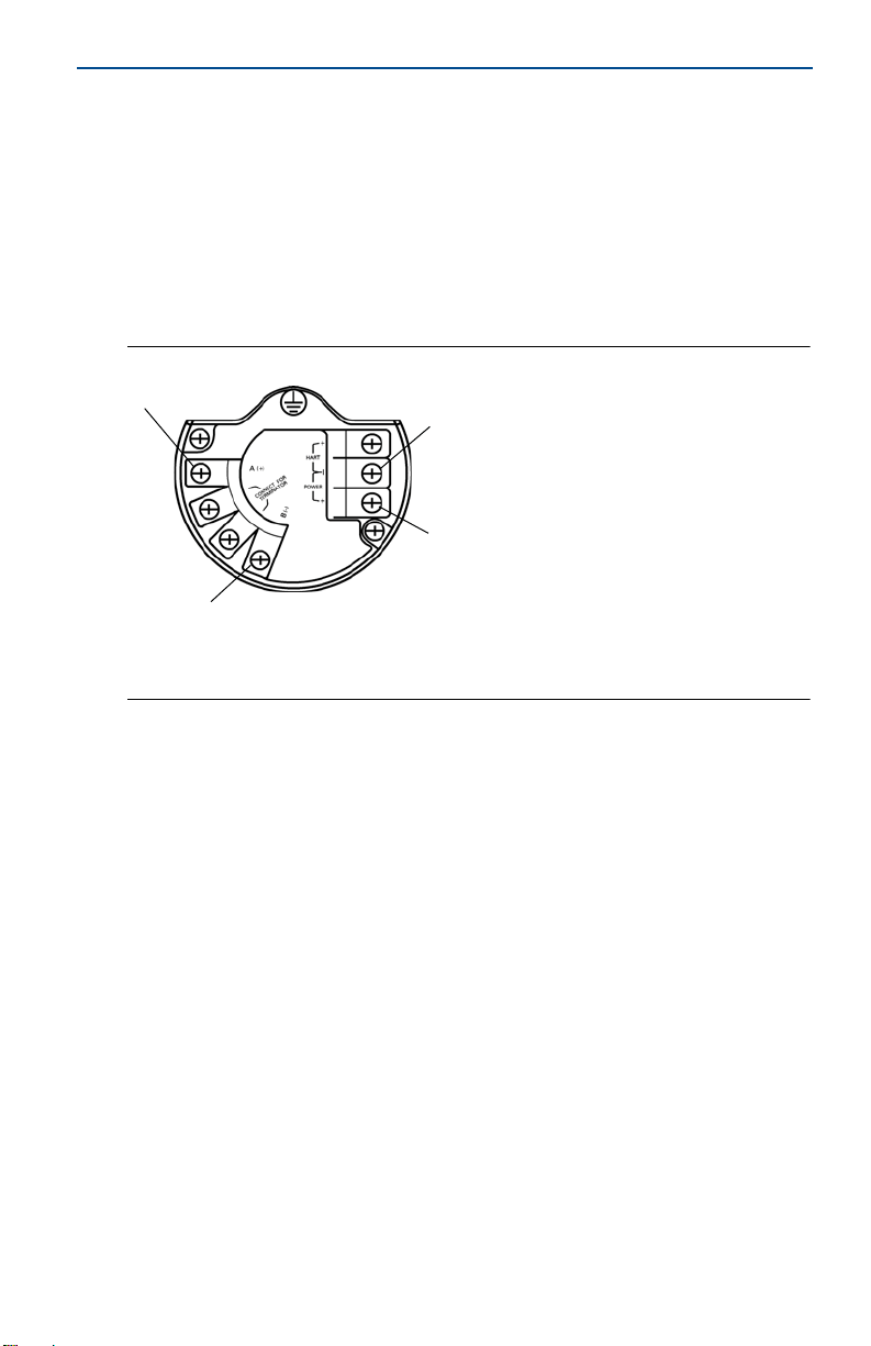
2.2 Power and data wiring
1. Remove housing cover labeled “Field Terminals.”
2. Connect the positive power lead to the “+” power terminal and the negative
power lead to the “–” terminal.
3. Connect the Data + lead to the “A (+)” terminal and the Data – lead to the “B
(–)” terminal.
4. Plug and seal any unused conduit connections.
5. Replace the housing cover.
Figure 6. Smart Wireless Field Link Terminal Diagram
A
A. Data A (+)
B. Data B (
B
C. +10.5 to 30 VDC
–)
D. Return
D
C
June 2017
2.3 Grounding
The Field Link enclosure should always be grounded in accordance with national
and local electrical codes. The most effective grounding method is a direct
connection to earth ground with minimal impedance. Ground the Field Link by
connecting the external ground lug to earth ground. The connection should be
1 Ω or less.
3.0 Verify operation
3.1 Power-up sequence
Upon applying power to the Field link the LCD display meter will activate and
display a series of startup screen. The following screens are displayed during
startup.
1. Startup Screen 1 – All segments on
2. Startup Screen 2 – Device Identification
3. Startup Screen 3 – Tag
4. Startup Screen 4 – Status
6
Page 7

June 2017
A
B
C
D
Quick Start Guide
3.2 Normal operation
After the initial startup screens the Field Link will cycle through several periodic
screens.
1. Electronics Temperature Screen
2. Percent Range Screen
3. Wired Interface Usage
4. Radio Interface Usage
The Field Link will continue to rotate through each periodic screen through the
course of normal operation. If any diagnostic or fault condition occurs, a
corresponding diagnostics screen will appear.
4.0 Reference information
Figure 7. Smart Wireless Field Link Terminal Diagram
A. Data A (+)
B. Data B (
–)
C. +10.5 to 30 VDC
D. Return
Note
The Smart Wireless Field Link requires separate twisted shield pairs (four wires) for power
and data.
7
Page 8

Quick Start Guide
Figure 8. Smart Wireless Field Link Dimensional Drawing
June 2017
C
90°
D
12.43
(316)
10.91
(277)
4.20
(107)
A
3.55
(90.17)
5.51
(140)
A. 23 Conduit plug
B. Possible antenna rotation shown
B
C. Extended range antenna
D. WirelessHART
3.55
(90.17)
5.51
(140)
®
antenna
Tabl e 1. Smart Wireless Field Link Specifications
Item Specifications
Input Power 10.5 – 30 VDC
Operating Temperature –40 to 185 °F (–40 to 85 °C)
Wiring (Power) 24 AW G - 14 AWG t wisted sh ielded pair
Wiring (RS-485 Communications)
Wiring Distance 656 ft. (200 m)
Wireless Protocol WirelessHART, 2.4 – 2.5 GHz DSSS
Wireless Output Power, EIRP 10 dBm with WK antenna and 12.5 dBm with WM antenna
Mounting All SST, 2-in. pipe and panel mount bracket
Humidity 0 – 90% relative humidity
24 AW G - 14 AWG t wisted sh ielded pair
Less than 15 pF/ft capacitance.
(1)
1
5.21
(132)
1. Ambient temperatures above 60 °C require wiring rated to at least 5 °C above max ambient temperature.
8
Page 9

June 2017
Quick Start Guide
5.0 Ordering information
Table 2. Smart Wireless Field Link
H The Standard offering represents the most common options. The starred options (H) should be selected for best delivery.
The Expanded offering is subject to additional delivery lead time.
Model Product description
781 Smart Wireless Field Link
Physical connection
A1 RS485
Housing
D Dual compartment housing - Aluminum
E Dual compartment housing - Stainless Steel
Conduit threads
1
2 M20
Product certifications
I5 FM Intrinsically Safe, Non-incendive
I6 CSA Intrinsically Safe
I1 ATEX Intrinsically Safe
I7 IECEx Intrinsic Safety
KL FM & CSA Class 1 Division 1, ATEX Zone 0 Intrinsically Safe
NA No Approvals
Wireless update rate, operating frequency and protocol
WA3 User configurable update rate, 2.4 GHz DSSS, WirelessHART
Omnidirectional wireless antenna and SmartPower™
WK3 External antenna, line pow er 10 – 30 VDC
WM3 Extended range, external antenna, line power 10 – 30 VDC
1
/2 – 14 NPT
H
H
H
H
H
H
H
H
H
H
H
H
H
H
Options (Include with selected model number)
Meter
M5 LCD disp lay
Gland and connector options
G2 Cable gland (7,5 mm – 11,9 mm)
G4 Thin wire cable gland (3 mm – 8 mm)
Typical model number: 781 A1 D 1 KL WA3 WK3 M5
H
9
Page 10

Quick Start Guide
6.0 Product Certifications
Rev 1.1
6.1 European Directive Information
A copy of the EC Declaration of Conformity can be found at the end of the Quick
Start Guide. The most recent revision of the EC Declaration of Conformity can be
found at www.rosemount.com.
6.2 Ordinary Location Certification
As standard, the transmitter has been examined and tested to determine the
design meets the basic electrical, mechanical, and fire protection requirements
by a nationally recognized test laboratory (NRTL) as accredited by the Federal
Occupational Safety and Health Administration (OSHA).
6.3 Installing in North America
The US National Electrical Code (NEC) and the Canadian Electrical Code (CEC)
permit the use of Division marked equipment in Zones and Zone marked
equipment in Divisions. The markings must be suitable for the area classification,
gas, and temperature class. This information is clearly defined in the respective
codes.
USA
I5 USA Intrinsically Safe (IS), Nonincendive (NI) and Dust-ignitionproof
Certificate: FM 3040398
Standards: FM Class 3600 – 1998, FM Class 3610 – 2010, FM Class 3611 – 2004,
FM Class 3810 – 2005, ANSI/NEMA 250 – 2003, ANSI/IEC 60529 – 2004;
Markings: IS CL I, DIV 1, GP A, B, C, D; CL II, DIV 1, GP E, F, G; Class III T4;
Class 1, Zone 0 AEx ia IIC T4;
NI CL I, DIV 2, GP A, B, C, D T4;
DIP CL II, DIV 1, GP E, F, G; CL III T4;
when installed per drawing 00781-1010
T4(-40 °C ≤ T
Input parameters
(power terminals)
V
= 30 V V
MAX/Ui
I
= 200 mA I
MAX/Ii
P
= 1 W P
MAX/Pi
Ci = 10 nF Ci = 5 nF Ca/Co = 10 nF
Li = 3.3 μH Li = 2.2 μH La/Lo= 3.3 μH
≤ +70 °C)
a
Input parameters
(sensor terminals)
MAX/Ui
MAX/Ii
MAX/Pi
Output parameters
(sensor terminals)
= 11 V Voc/Uo = 7.14 V
= 300 mA Isc/Io = 112 mA
= 1 W P
MAX/Po
= 640 mW
June 2017
Special Conditions for Safe Use (X):
1. The Model 781 transmitter housing contains aluminum and is considered a potential
risk of ignition by impact or fric tion. Care must be taken into account during installation
and use to prevent impact and friction.
2. The surface resistivity of the unit is greater than 1 gigaohm. To avoid electrostatic
charge buildup, it must not be rubbed or cleaned with solvents or a dry cloth.
3. The Model 781 transmitter will not pass the 500 Vrms electric strength test and this
must be taken into account during installation.
10
Page 11

June 2017
Quick Start Guide
Canada
I6 Canada Intrinsically Safe
Certificate: CSA 2330424
Standards: CSA C22.2 No. 0-10, CSA C22.2 No.94-M91, CSA Std. C22.2 No. 142-1987,
CSA-C22.2 No. 157-92, CSA Std. C22.2 No. 60529 – 2005
Markings: Intrinsically Safe Class I, Division 1, Groups A, B, C, and D T3C (T
Type 4X; IP 66/67; when installed per 00781-1011
Europe
I1 ATE X In tri nsi c Sa fet y
Certificate: Baseefa11ATEX0059X
Standards: EN 60079-0: 2009, EN 60079-11: 2007
Markings: II 1 G Ex ia IIC T4 Ga, T4(–40 °C ≤ T
Input parameters
(power terminals)
Ui = 30 V Ui = 11 V Uo = 7.14 V
Ii = 200 mA Ii = 300 mA Io = 112 mA
Pi = 1 W Pi = 1 W Po = 1 W
Ci = 0 μF Ci = 5.1 nF Co = 13.9 μF
Li = 0 mH Li = 0 mH Lo=1000 μH
Input parameter s
(RS485)
Special Conditions for Safe Use (X):
1. The plastic antenna may present a potential electrostatic ignition hazard and must not
be rubbed or cleaned with a dry cloth.
2. The Model 781 enclosure is made of aluminum alloy and given a protective paint finish;
howev er, car e should be t aken to pr otect i t from im pact or abrasio n if loca ted in a zo ne 0
environment.
3. The apparatus is not capable of withstanding the 500 V isolation test required by EN
60079-11:2007 Clause 6.3.12. This must be taken into account when installing the
apparatus.
≤ +70 °C)
a
Output parameters
(RS485)
≤ +60 °C)
a
International
I7 IECEx Intrinsic Safety
Certificate: IECEx BAS 11.0026X
Standards: IEC 60079-0: 2004, IEC 60079-0: 2007-10, IEC 60079-11: 2006
Markings: Ex ia IIC T4 Ga, T4(–40 °C ≤ T
Input parameters
(power terminals)
Ui = 30 V Ui = 11 V Uo = 7.14 V
Ii = 200 mA Ii = 300 mA Io = 112 mA
Pi = 1 W Pi = 1 W Po = 1 W
Ci = 0 μF Ci = 5.1 nF Co = 13.9 μF
Li = 0 mH Li = 0 mH Lo=1000 μH
Input parameter s
(RS485)
≤ +70 °C)
a
Output parameters
(RS485)
11
Page 12

Quick Start Guide
Special Conditions for Safe Use (X):
1. The plastic antenna may present a potential electrostatic ignition hazard and must not
be rubbed or cleaned with a dry cloth.
2. The Model 781 enclosure is made of aluminum alloy and given a protective paint finish;
however, care should be taken to protect it from impact or abrasion if located in a zone
0 environment
3. The apparatus is not capable of withstanding the 500 V isolation test required by EN
60079-11:2007 Clause 6.3.12. This must be taken into account when installing the
apparatus.
China
I3 China Intrinsic Safety
Certificate: GYJ13.1444X
Standards: GB3836.1-2010, GB3836.4-2010, GB3836.20-2010
Markings: Ex ia IIC T4 Ga, –40 ~ + 70 °C
Special Condition for Safe Use (X):
1. See certificate for special conditions.
EAC – Belarus, Kazakhstan, Russia
IM Technical Regulation Customs Union (EAC) Intrinsic Safety
Certificate: RU C-US.Gb05.B.00643
Markings: 0Ex ia IIC T4 Ga X
Input parameters
(power terminals)
Ui = 30 B Ui = 11 B Uo = 7.14 B
Ii = 200 MA Ii = 300 MA Io = 112 MA
Pi = 1 BT Pi = 1 BT Po = 1 BT
Ci = 0 мкΦ Ci = 5.1 HΦ Co = 13.9 мкΦ
Li = 0 MГH Li = 0 MГH Lo=0 MГH
Input parameters
(RS485)
Output parameters
(RS485)
June 2017
Special Condition for Safe Use (X):
1. See certificate for special conditions.
Combinations
KD Combination of I1, I5, and I6
KL Combination of I1, I5, I6, and I7
12
Page 13

June 2017
EU Declaration of Conformity
No: RMD 1083 Rev. F
Page 1 of 3
We,
Rosemount, Inc.
8200 Market Boulevard
Chanhassen, MN 55317-9685
USA
declare under our sole responsibility that the product,
Rosemount 781 Wireless Field Link
manufactured by,
Rosemount, Inc.
8200 Market Boulevard
Chanhassen, MN 55317-9685
USA
to which this declaration relates, is in conformity with the provisions of the European Union
Directives, including the latest amendments, as shown in the attached schedule.
Assumption of conformity is based on the application of the harmonized standards and, when
applicable or required, a European Union notified body certification, as shown in the attached
schedule.
Vice President of Global Quality
Chris LaPoint
6-June-2017
Figure 9. Rosemount 781 Declaration of Conformity
Quick Start Guide
(signature)
(name)
(function)
(date of issue)
13
Page 14

Quick Start Guide
EU Declaration of Conformity
No: RMD 1083 Rev. F
Page 2 of 3
EMC Directive (2014/30/EU)
Harmonized Standards:
EN 61326-1:2013
Radio Equipment Directive (RED) (2014/53/EU)
Harmonized Standards:
EN 300 328: V2.1.1
EN 301 489-17: V3.2.0
EN 60950-1: 2006+A11+A12+A1+A2
EN 50371:2002
ATEX Directive (2014/34/EU)
Baseefa11ATEX0059X – Intrinsic Safety Certificate
Equipment Group II, Category 1 G
Ex ia IIC T4 Ga
Standards Used:
EN 60079-0: 2009 (A review against EN60079-0:2012, which is
harmonized, shows no significant changes relevant to this equipment
so EN60079-0:2009 continues to represent “State of the Art”)
EN 60079-11: 2007 (A review against EN60079-11:2012, which is
harmonized, shows no significant changes relevant to this equipment
so EN60079-11:2007 continues to represent “State of the Art”)
June 2017
14
Page 15

June 2017
EU Declaration of Conformity
No: RMD 1083 Rev. F
Page 3 of 3
ATEX Notified Body
SGS Baseefa Limited [Notified Body Number: 1180]
Rockhead Business Park
Staden Lane
Buxton, Derbyshire
SK17 9RZ United Kingdom
ATEX Notified Body for Quality Assurance
SGS Baseefa Limited [Notified Body Number: 1180]
Rockhead Business Park
Staden Lane
Buxton, Derbyshire
SK17 9RZ United Kingdom
Quick Start Guide
15
Page 16

Quick Start Guide
ᴹ
China RoHS
㇑᧗⢙䍘䎵䗷ᴰབྷ⎃ᓖ䲀٬Ⲵ䜘Ԧරࡇ㺘
List of
Rosemount 781
Rosemount 781 Parts with China RoHS Concentration above MCVs
䜘Ԧ〠
Part Name
ᴹᇣ⢙䍘䍘/ Hazardous Substances
䫵
Lead
(Pb)
⊎
Mercury
(Hg)
䭹
Cadmium
(Cd)
ޝԧ䬜䬜
Hexavalent
Chromium
(Cr +6)
ཊⓤ㚄㚄㤟
Polybrominated
biphenyls
(PBB)
ཊⓤ㚄㚄㤟䟊
Polybrominated
diphenyl ethers
(PBDE)
⭥ᆀ㓴Ԧ
Electronics
Assembly
X O O O O
O
༣փ㓴Ԧ
Housing
Assembly
X O O X O
O
ᵜ㺘Ṭ㌫ᦞ
SJ/T11364
Ⲵ㿴ᇊ㘼ࡦ
This table is proposed in accordance with the provision of SJ/T11364.
O:
Ѫ䈕䜘ԦⲴᡰᴹ൷䍘ᶀᯉѝ䈕ᴹᇣ⢙䍘Ⲵ䟿൷վҾ
GB/T 26572
ᡰ㿴ᇊⲴ䲀䟿㾱≲
O: Indicate that said hazardous substance in all of the homogeneous materials for this part is below the limit requirement of
GB/T 26572.
X:
Ѫ൘䈕䜘Ԧᡰ֯⭘Ⲵᡰᴹ൷䍘ᶀᯉ䟼ˈ㠣ቁᴹа㊫൷䍘ᶀᯉѝ䈕ᴹᇣ⢙䍘Ⲵ䟿儈Ҿ
GB/T 26572
ᡰ㿴ᇊⲴ䲀䟿㾱≲
X: Indicate that said hazardous substance contained in at least one of the homogeneous materials used for this part is above
the limit requirement of GB/T 26572.
June 2017
16
Page 17

June 2017
Quick Start Guide
17
Page 18

*00825-0100-4421*
Quick Start Guide
00825-0100-4421, Rev CB
Global Headquarters
Emerson Automation Solutions
6021 Innovation Blvd.
Shakopee, MN 55379, USA
+1 800 999 9307 or +1 952 906 8888
+1 952 949 7001
RFQ.RMD-RCC@Emerson.com
North America Regional Office
Emerson Automation Solutions
8200 Market Blvd.
Chanhassen, MN 55317, USA
+1 800 999 9307 or +1 952 906 8888
+1 952 949 7001
RMT-NA.RCCRFQ@Emerson.com
Latin America Regional Office
Emerson Automation Solutions
1300 Concord Terrace, Suite 400
Sunrise, FL 33323, USA
+1 954 846 5030
+1 954 846 5121
RFQ.RMD-RCC@Emerson.com Linkedin.com/company/Emerson-Process-Management
Europe Regional Office
Emerson Automation Solutions
Neuhofstrasse 19a P.O. Box 1046
CH 6340 Baar
Switzerland
+41 (0) 41 768 6111
+41 (0) 41 768 6300
RFQ.RMD-RCC@Emerson.com
Asia Pacific Regional Office
Emerson Automation Solutions
1 Pandan Crescent
Singapore 128461
+65 6777 8211
+65 6777 0947
Enquiries@AP.Emerson.com
Middle East and Africa Regional Office
Emerson Automation Solutions
Emerson FZE P.O. Box 17033
Jebel Ali Free Zone - South 2
Dubai, United Arab Emi rates
+971 4 8118100
+971 4 8865465
RFQ.RMTMEA@Emerson.com
Twitter.com/Rosemount_News
Facebook.com/Rosemount
Youtube.com/us er/RosemountMeasur ement
Google.com/+RosemountMeasurement
Standard Terms and Conditions of Sale can be found at
www.Emerson.com/en-us/pages/Terms-of-Use.aspx
The Emerson logo is a trademark and service mark of Emerson
Electric Co.
SmartPower, Rosemount, and Rosemount logotype are
trademarks of Emerson.
WirelessHART is a registered trademark of the FieldComm Group.
All other marks are the property of their respective owners.
© 2017 Emerson Process Management. All rights reserved.
June 2017
 Loading...