

Page 1

Quick Start Guide
00825-0100-4075, Rev GB
Emerson™ Wireless THUM™ Adapter
June 2017
Page 2
Quick Start Guide
June 2017
NOTICE
This guide provides basic guidelines for the Wireless THUM Adapter. It does not provide instructions for
detailed configuration, diagnostics, maintenance, service, troubleshooting, or installations. Refer to the THUM
Adapter Reference Manual
Emerson.com/Rosemount
This device complies with Part 15 of the FCC Rules. Operation is subjec t to the following conditions. This device
may not cause harmful interference. This device must accept any interference received, including interference
that may cause undesired operation.
Explosions could result in death or serious injury.
Installation of this transmitter in an explosive environment must be in accordance with the appropriate local,
national, and international standards, codes, and practices. Review the Product Certifications section for any
restrictions associated with a safe installation.
Before connecting a Field Communicator in an explosive atmosphere, ensure the instruments are installed
in accordance with intrinsically safe or non-incendive field wiring practices.
Electrical shock can result in death or serious injury.
Avoid contact with the leads and terminals. High voltage that may be present on leads can cause electrical
shock.
This device must be installed to ensure a minimum antenna separation distance of 7.87-in. (20 cm) from all
persons.
for more instruction. The manual and this guide are also available electronically on
.
During normal operation, or in fault condition, the THUM Adapter will cause a 2.5 V drop in the conn ected loop.
It is important to ensure that the power supply can provide at least 2.5 V more than the minimum operating
voltage of the wired device to make sure it works properly with the THUM Adapter installed. To determine the
minimum operating voltage for the wired device, review the wired device operation and installation manual.
Contents
Wireless considerations . . . . . . . . . . . . . . page 3
Bench top configuration . . . . . . . . . . . . . . page 5
Physical installation . . . . . . . . . . . . . . . . . . page 6
Direct mount . . . . . . . . . . . . . . . . . . . . . . . page 6
Remote mount . . . . . . . . . . . . . . . . . . . . . . page 7
Device network configuration . . . . . . . . page 20
2
AMS Device Manager . . . . . . . . . . . . . . . page 20
Field Communicator . . . . . . . . . . . . . . . . page 21
Loop current test . . . . . . . . . . . . . . . . . . . page 21
Verify operation . . . . . . . . . . . . . . . . . . . . page 23
Reference information . . . . . . . . . . . . . . page 24
Product Certifications . . . . . . . . . . . . . . . page 25
Page 3
June 2017
1.0 Wireless considerations
1.1 Power up sequence
Power should not be applied to any wireless device until the Wireless Gateway
(“Gateway”) is installed and functioning properly. Wireless devices should also
be powered up in order of proximity from the Gateway, beginning with the
closest. This will result in a simpler and faster network installation. Enable Active
Advertising on the Gateway to ensure that new devices join the network faster.
For more information see the Wireless Gateway Reference Manual
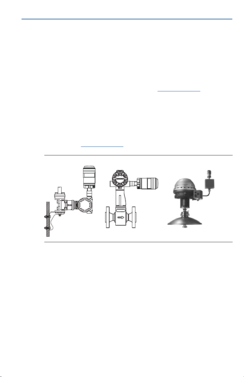
1.2 THUM Adapter position
THUM Adapter should be positioned vertically straight up, and should be
approximately 3 ft. (1 m) from any large structure, building or conductive
surface to allow for clear communication to other devices. If the THUM Adapter
is mounted horizontally wireless communication range may be decreased. The
THUM Adapter should not be mounted vertically straight down. See Wireless
THUM Adapter Reference Manual
Figure 1. THUM Adapter Position
for more information.
Quick Start Guide
.
1.3 Conduit entry
When installing the THUM Adapter into the conduit entry of a wired device, use
an approved thread sealant. Thread sealant provides a water tight seal. The
thread sealant also provides lubrication to ensure easy removal of the THUM
Adapter.
1.4 M20 conduit adapter
When using the M20 Conduit Adapter on the THUM Adapter, use an approved
thread sealant and tighten wrench tight to the THUM Adapter. When installing
the M20 conduit adapter into a conduit, tighten to 32.5 N-m/25 ft-lb to ensure
water tight seal.
Field Communicator connections
In order for the Field Communicator to interface with the THUM Adapter, the
3
Page 4

Quick Start Guide
wired device must be powered. The Field Communicator must be put into poll
mode and should use the THUM Adapter address of 63.
1.5 Power supply
Minimum loop load of 250 Ohms.
The THUM Adapter communicates via and derives power from a standard
4–20 mA/HART® loop. The THUM Adapter causes a small voltage drop on
the loop which is linear from 2.25 V at 3.5 mA to 1.2 V at 25 mA. Under fault
conditions, the maximum voltage drop is 2.5 V. The THUM Adapter will not
affect the 4–20 mA signal under normal or fault conditions as long as the
loop has at least a 2.5 V margin at the maximum loop current (25 mA for a
typical 4–20 mA/HART device).
Limit the power supply to 0.5 Amps maximum and voltage to 55 Vdc.
Loop current THUM Adapter voltage drop
3.5 mA 2.25 V
25 mA 1.2 V
1.6 Load resistor
If required, add a load resistor as shown in Figure 8 on page 10, Figure 12 on
page 13, and Figure 16 on page 15. The resistor should be adequately rated for
the application (1W minimum) and be compatible with the supplied splice
connector which accepts wire sizes from 14 to 22 AWG.
June 2017
1.7 Loop
To ensure proper operation, the THUM Adapter should not be installed on a
HART loop with other active HART masters. HART masters that are active
periodically, such as a field communicator can be used on a loop with a THUM
Adapter.
4
Page 5
June 2017
A
Green
Red
Black
White
Yellow
B
C
D
+
-
Green
Red
Black
White
Yellow
A
B
C
+
-
D
2.0 Bench top configuration
When performing bench top configuration it is suggested that you connect the
THUM Adapter to a wired device. If this is not possible, the following wiring
diagrams can be used. For bench top configuration, ensure the power supply
used is limited to 0.5 Amps maximum.
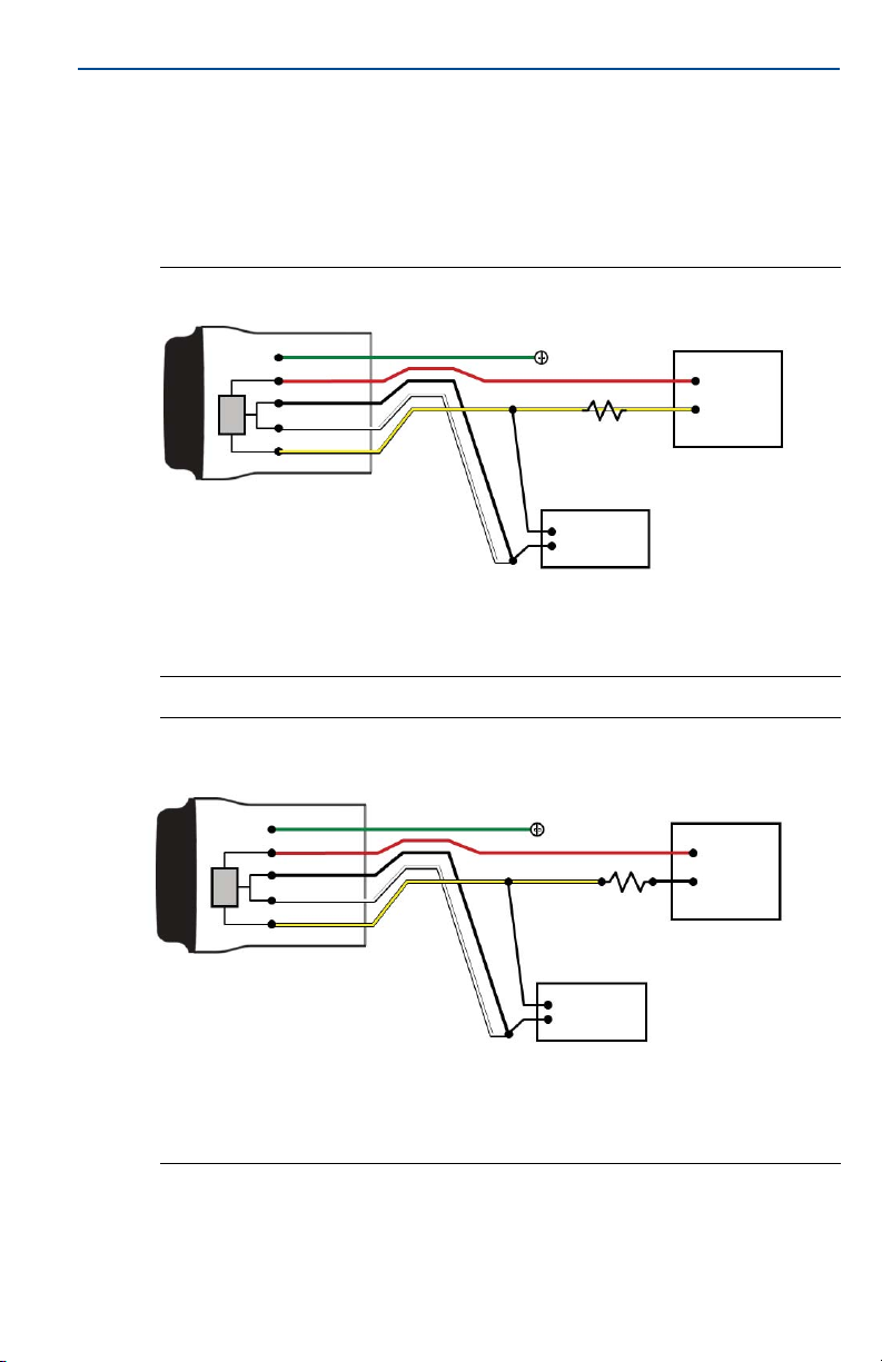
Figure 2. THUM Adapter Only, Powered by a Current Source
A. THUM Adapter C. 20 mA current source
B. Ground D. HART Modem
Quick Start Guide
Figure 3. THUM Adapter Only, Powered by a 24 V Power Supply with 1200
Ohm Resistor to Limit Current to 20 mA
A. THUM Adapter C. 20 V power supply
B. Ground D. HART Modem
5
Page 6
Quick Start Guide
3.0 Physical installation
The THUM Adapter can be installed in one of two configurations:
1. Direct mount: The THUM Adapter is connected directly to the conduit entry
of the wired device.
2. Remote mount: The THUM Adapter is mounted separate from the wired
device housing and then connected to the wired device using conduit or
other suitable means.
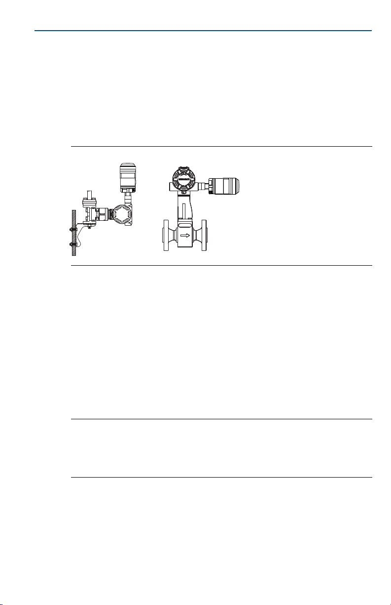
Figure 4. Direct Mount
4.0 Direct mount
1. Install the HART device according to standard installation practices and the
manufacturer’s instructions, being sure to use an approved thread sealant on
all connections.
2. Attach the THUM Adapter to the wired device as shown in Figure 4 on page 6.
3. Connect the THUM Adapter to the HART wired device using the wiring
diagrams (see Figure 21 on page 19, Figure 8 on page 10, Figure 10 on
page 11, and Figure 12 on page 13).
4. Close the housing cover on the HART wired device, so that metal touches
metal, but do not over tighten to prevent damaging the unit.
June 2017
Note
Two splice connectors are included with the THUM Adapter. The first is a two connection
splice. The second is a three connection splice for use with a resistor, if there is not enough
resistance in the loop. Both of these splice connectors can accept 14 to 22 gauge wire. See
wired device reference manual for information on the required loop resistance.
6
Page 7

June 2017
5.0 Remote mount
Figure 5. Remote Mount
1. Install the HART device according to standard installation practices and the
manufacturer’s instructions, being sure to use an approved thread sealant on
all connections.
2. The THUM Adapter should be mounted as shown in Figure 5 on page 7.
3. Ground the Remote Mount Kit per local practices.
4. Connect the THUM Adapter to the wired device using standard practices.
Wire running from the THUM Adapter to the wired device should be shielded
or in conduit when installed in electrically noisy environments.
5. Connect the THUM Adapter to the HART wired device using the wiring
diagrams (see Figure 21 on page 19, Figure 8 on page 10, Figure 10 on
page 11, and Figure 12 on page 13).
6. Close the housing cover on the HART wired device, so that metal touches
metal, but do not over tighten to prevent damaging the unit.
Quick Start Guide
Note
Two splice connectors are included with the THUM Adapter. The first is a two connection
splice. The second is a three connection splice for use with a resistor, if there is not enough
resistance in the loop. Both of these splice connectors can accept 14 to 22 gauge wire. See
wired device reference manual for information on the required loop resistance.
7
Page 8

Quick Start Guide
5.1 Wiring diagrams
The following is a list of the figure titles and page numbers for each direct mount
and remote mount wiring diagram:
Figure 6 - “Direct Mount Wiring Diagram for 2-Wire Device” on page 9
Figure 7 - “Remote Mount Wiring Diagram for 2-Wire Device” on page 10
Figure 8 - “Direct Mount Wiring Diagram for 2-Wire Device with Resistor” on
page 10
Figure 9 - “Remote Mount Wiring Diagram for 2-Wire Device with Resistor” on
page 11
Figure 10 - “Direct Mount Wiring Diagram for 4-Wire Passive Device” on page 11
Figure 11 - “Remote Mount Wiring Diagram for 4-Wire Passive Device” on
page 12
Figure 12 - “Direct Mount Wiring Diagram for 4-Wire Passive Device with
Resistor” on page 13
Figure 13 - “Remote Mount Wiring Diagram for 4-Wire Passive Device with
Resistor” on page 13
Figure 14 - “Direct Mount Wiring Diagram for 4-Wire Active Device” on page 14
Figure 15 - “Remote Mount Wiring Diagram for 4-Wire Active Device” on
page 15
Figure 16 - “Direct Mount Wiring Diagram for 4-Wire Active Device with
Resistor” on page 15
Figure 17 - “Remote Mount Wiring Diagram for 4-Wire Active Device with
Resistor” on page 16
Figure 18 - “Direct Mount Wiring Diagram for 4-Wire Active Device with No
4–20 mA Loop” on page 17
Figure 19 - “Remote Mount Wiring Diagram for 4-Wire Active Device with No
4–20 mA Loop” on page 18
Figure 20 - “THUM Adapter only, Powered by a 24 V Power Supply with 1200
Ohm resistor to limit current to 20 mA” on page 18
Figure 21 - “THUM Adapter only, Powered by a 24 V Power Supply with 1200
Ohm resistor to limit current to 20 mA” on page 19
June 2017
8
Page 9
June 2017
A
Green
Red
Black
White
Yellow
4 -20 mA Loop +
4 -20 mA Loop -
B
C
D
E
F
- PWR/COMM
+ PWR/COMM
Quick Start Guide
Figure 6. Direct Mount Wiring Diagram for 2-Wire Device
A. THUM Adapter D. Splice connector
B. Wired device E. Load resistor ≥ 250 Ω
C. Ground F. Power supply
Note
In order for the THUM Adapter to function properly there must be at least 250 Ohms
resistance in the loop. If the 4–20 mA loop does not have the required resistance, wire a
resistor as shown in Figure 8 on page 10, Figure 12 on page 13, or Figure 16 on page 15 as
applicable.
9
Page 10
Quick Start Guide
A
B
Green
C
Red
Black
White
Yellow
D
+ COMM
- COMM
To Wired Device
4 -20 mA Loop +
4 -20 mA Loop -
E
F
Figure 7. Remote Mount Wiring Diagram for 2-Wire Device
A. THUM Adapter D. Shield wire
B. Remote mount housing E. Load resistor ≥ 250 Ω
C. Ground F. Power supply
June 2017
Figure 8. Direct Mount Wiring Diagram for 2-Wire Device with Resistor
A
Green
Red
Black
A. THUM Adapter D. Splice connector
B. Wired device E. Load resistor ≥ 250 Ω
C. Ground F. Power supply
White
Yellow
10
B
C
- PWR/COMM
+ PWR/COMM
4 -20 mA Loop +
4 -20 mA Loop -
E
D
F
Page 11
June 2017
A
B
C
Green
White
Yellow
Red
Black
D
E
+ COMM
- COMM
To Wired Device
4 - 20 mA Loop +
4 - 20 mA Loop -
+
-
F
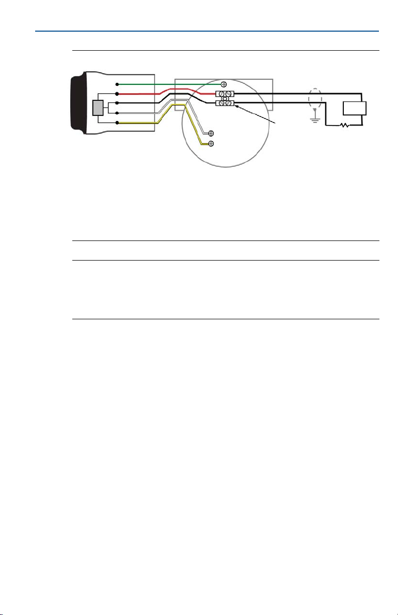
A
Green
Red
Black
White
Yellow
B
C
COMM +
COMM -
Power -
Power +
D
E
4 - 20 mA Loop +
4 -20 mA Loop -
F
Quick Start Guide
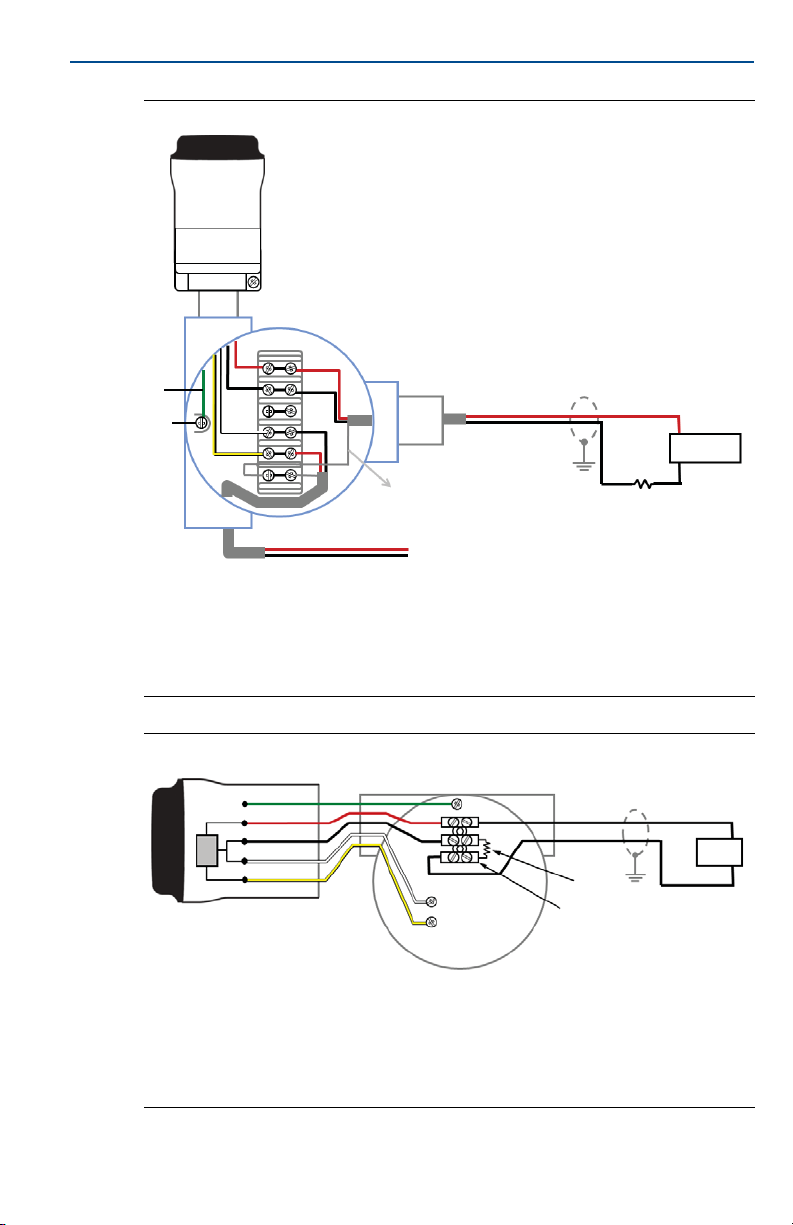
Figure 9. Remote Mount Wiring Diagram for 2-Wire Device with Resistor
A. THUM Adapter D. Shield wire
B. Remote mount housing E. Load resistor ≥ 250 Ω
C. Ground F. Power supply
Figure 10. Direct Mount Wiring Diagram for 4-Wire Passive Device
A. THUM Adapter D. Splice connector
B. Wired device E. Load resistor ≥ 250 Ω
C. Ground F. Power supply
11
Page 12

Quick Start Guide
A
B
Green
C
D
+ COMM
- COMM
4 -20 mA Loop +
4 -20 mA Loop -
To Wired Device
E
F
+
-
Note
A passive loop exists when the wired device is not supplying power to the 4–20 mA loop. It
is important to verify if the wired device is operating in active or passive mode.
Figure 11. Remote Mount Wiring Diagram for 4-Wire Passive Device
June 2017
A. THUM Adapter D. Shield wire
B. Remote mount housing E. Load resistor ≥ 250 Ω
C. Ground F. Power supply
12
Page 13

June 2017
A
Green
Red
Black
White
Yellow
B
C
COMM +
COMM -
Power +
Power -
4 - 20 mA Loop +
4 -20 mA Loop -
D
E
+
-
F
Green
A
C
B
D
+ COMM
- COMM
To Wired Device
4 - 20 mA Loop +
4 - 20 mA Loop -
E
+
-
F
Quick Start Guide
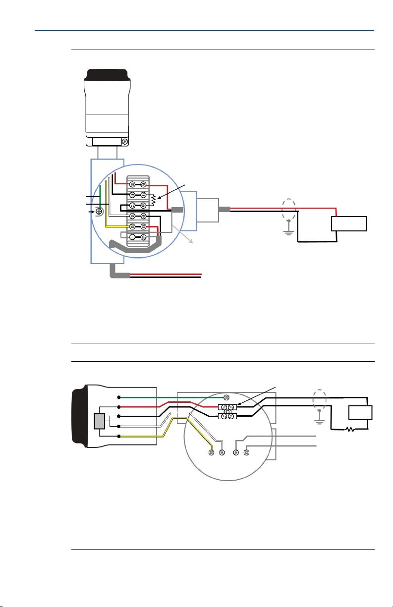
Figure 12. Direct Mount Wiring Diagram for 4-Wire Passive Device with
Resistor
A. THUM Adapter D. Splice connector
B. Wired device E. Load resistor ≥ 250 Ω
C. Ground F. Power supply
Figure 13. Remote Mount Wiring Diagram for 4-Wire Passive Device with
Resistor
A. THUM Adapter D. Shield wire
B. Remote mount housing E. Load resistor ≥ 250 Ω
C. Ground F. Power supply
13
Page 14

Quick Start Guide
A
Green
Yellow
White
Black
Red
B
COMM +
COMM -
Power +
Power -
C
D
E
F
+
-
Figure 14. Direct Mount Wiring Diagram for 4-Wire Active Device
A. THUM Adapter D. Splice connector
B. Wired device E. Load resistor ≥ 250 Ω
C. Ground F. I nput card
Note
An active loop exists when the wired device is supplying the power to the 4–20 mA loop. It
is important to verify if the wired device is operating in active or passive mode.
June 2017
14
Page 15

June 2017
A
B
Green
C
D
+ COMM
- COMM
To Wired Device
4-20 mA Loop +
4-20 mA Loop -
E
F
A
B
C
D
E
F
+
_
Green
Yellow
White
Black
Red
Comm +
Comm -
Power +
Power -
Quick Start Guide
Figure 15. Remote Mount Wiring Diagram for 4-Wire Active Device
A. THUM Adapter D. Shield wire
B. Remote mount housing E. Load resistor ≥ 250 Ω
C. Ground F. Input card
Figure 16. Direct Mount Wiring Diagram for 4-Wire Active Device with
Resistor
A. THUM Adapter F. Splice connector
B. Wired device G. Load resistor ≥ 250 Ω
C. Ground H. Input card
15
Page 16

Quick Start Guide
A
B
C
D
E
E
F
4 - 20 mA Loop +
4 - 20 mA Loop -
COMM +
COMM -
G
Figure 17. Remote Mount Wiring Diagram for 4-Wire Active Device with
June 2017
Resistor
A. THUM Adapter E. Load resistor ≥ 250 Ω
B. Remote mount housing F. I np ut card
C. Ground G. To wired device
D. Shield wire
16
Page 17

June 2017
Quick Start Guide
Figure 18. Direct Mount Wiring Diagram for 4-Wire Active Device with No
4–20 mA Loop
A
Green
Yellow
White
Black
Red
COMM +
COMM -
B
C
Power -
Power +
A. THUM Adapter D. Splice connector
B. Wired device E. Load resistor ≥ 250 Ω
C. Ground
D
E
17
Page 18

Quick Start Guide
A
Green
Red
Black
White
Yellow
B
C
D
E
F
+
-
Figure 19. Remote Mount Wiring Diagram for 4-Wire Active Device with
Green
C
No 4–20 mA Loop
A
B
Red
Black
White
Yellow
June 2017
D
+ COMM
- COMM
To Wired Device
A. THUM Adapter C. Ground
B. Remote mount housing D. Load Resistor ≥ 250 Ω
Figure 20. THUM Adapter Only, Powered by a 24 V Power Supply with
1200 Ohm Resistor to Limit Current to 20 mA
A. THUM Adapter D. 250 Ω Resistor
B. Junction Box E. 1200 Ohm Resistor Required
C. Ground F. 24 V Power Supply
18
Page 19

June 2017
B
A
D
C
E
-
F
+
Green
W
B
R
Y
Quick Start Guide
Figure 21. THUM Adapter Only, Powered by a 24 V Power Supply with 1200
Ohm Resistor to Limit Current to 20 mA
A. THUM Adapter D. 250 Ω Resistor
B. Remote Mount Housing E. 1200 Ohm Resistor Required
C. Ground F. 24 V Power Supply
19
Page 20

Quick Start Guide
6.0 Device network configuration
In order to communicate with the Wireless Gateway, and ultimately the
Information System, the transmitter must be configured to communicate with
the wireless network. This step is the wireless equivalent of connecting wires
from a transmitter to the information system. Using a Field Communicator or
Device Manager, enter the Network ID and Join Key so that they match the
AMS
Network ID and Join Key of the gateway and other devices in the network. If the
Network ID and Join Key are not identical, the THUM Adapter will not
communicate with the network. The Network ID and Join Key may be obtained
from the Wireless Gateway on the Setup>Network>Settings page on the web
server, shown in Figure 22 on page 20.
Figure 22. Gateway Network Settings
June 2017
7.0 AMS Device Manager
Right click on the THUM Adapter and select Configure. When the menu opens,
select Join Device to Network and follow the method to enter the Network ID
and Join Key.
20
Page 21

June 2017
8.0 Field Communicator
The Network ID and Join Key may be changed in the wireless device by using the
following Fast Key sequence. Set both Network ID and Join Key.
Function Fast Key sequence Menu items
Wireless Setup 1, 4 Smart Power, Network ID, Set Join Key, Radio State
9.0 Loop current test
To verify the THUM Adapter will work under all conditions, a loop current test
should be performed. This test will exercise the loop under the highest possible
voltage drop conditions.
1. Place loop in manual control.
2. Drive loop to high alarm level. For details, see wired device instruction
manual.
When the THUM Adapter is connected to a valve, this will need to be
done at the current source and not from the valve.
When the THUM Adapter is connected to a transmitter, this will need to
be performed at the transmitter.
3. Place the THUM Adapter into fixed voltage drop mode.
AMS Device Manager
a. Right click on the THUM Adapter and select Configure.
b. When the menu opens, select Manual Setup from the window on the left
and select the Wired Device tab on the top.
c. Make sure the Time drop down menu at the bottom of the page has
Current selected.
d. Under the Voltage Drop drop down menu in the Smart Power Options
box, select Fixed Voltage Drop.
e. Select the Apply button to make any changes. See Figure 23 on page 22.
Quick Start Guide
Field Communicator
a. When communicating to the THUM Adapter select: Configure>Manual
setup> Wired Device>Voltage Drop Mode.
b. In the method select Fixed Voltage Drop.
Function Fast Key sequence Menu items
Voltage Drop 2, 2, 2, 2 Voltag e Drop
4. Verify the current on the loop reaches the high alarm levels.
5. Place the THUM Adapter into variable voltage drop mode.
21
Page 22

Quick Start Guide
AMS Device Manager
a. Right click on the THUM Adapter and select Configure.
b. When t he menu opens, selec t Manual Setup from the window on the left
c. Make sure the Time drop down menu at the bottom of the page has
d. Under the Voltage Drop drop down menu in the Smart Power Options
e. Select the Apply button to make any changes. See Figure 23 on page 22.
Field Communicator
a. When communicating to the THUM Adapter select: Configure>Manual
b. In the method select Variable Voltage Drop.
6. Remove loop from high alarm value.
Figure 23. AMS Configure Screen
June 2017
and select the Wired Device tab on the top.
Current selected.
box, select Fixed Voltage Drop.
setup>Wired Device>Voltage Drop Mode.
Function Fast Key sequence Menu items
Voltage Drop 2,2,2,2 Volt age Drop
22
Page 23

June 2017
10.0 Verify operation
Operation can be verified in three locations: by using the Field Communicator,
at the Gateway via the Wireless Gateway’s integrated web server, or via AMS
Device Manager.
10.1 Field Communicator
For HART Wireless transmitter communication, a THUM Adapter DD is
required.The Field Communicator must be put into poll mode using the THUM
Adapter address of 63. Use the wired device documentation to connect the Field
Communicator to the THUM Adapter.
Func tion Fast Key sequence Menu items
Communications 3, 3
10.2 Wireless Gateway
If the THUM Adapter was configured with the Network ID and Join Key, and
sufficient time has passed for network polling, the transmitter will be connected
to the network. To verify device operation and connection to the network with
the Wireless Gateway’s integrated web server, open the Wireless Gateway’s
integral web interface and navigate to the Explorer page.
Quick Start Guide
Join Status, Wireless Mode, Join Mode, Number of
Available Neighbors, Number of Advertisements Heard,
Number of Join Attempts
Note
It may take several minutes for the device to join the network.
10.3 AMS Device Manager
When the device has joined the network, it will appear in the Device Manager as
illustrated below:
23
Page 24

Quick Start Guide
10.4 Troubleshooting
If the device is not operating properly, refer to the troubleshooting section of
the manual. The most common cause of incorrect operation is the Network ID
and Join Key. The Network ID and Join Key in the device must match that of the
Wireless Gateway.
The Network ID and Join Key may be obtained from the Wireless Gateway on the
Setup>Network>Settings page on the web server. The Network ID and Join Key
may be changed in the wireless device by using the following Fast Key sequence.
Function Fast Key sequence Menu items
Wireless Setup 1, 4 Smar t Power, Network ID, Set Join Key, Radio State
11.0 Reference information
Note
In order to communicate with a Field Communicator, the wired device must be powered.
Table 1. THUM Adapter Fast Key Sequence
Function Fast Key sequence Menu items
Device Info 2, 2, 4, 3
Guided Setup 2, 1
Manual Setup 2, 2
Wireless 2, 2, 1
Manufacturer, Model, Final Assembly Number, Universal, Field
Device, Software, Hardware, Descriptor, Message, Date, Model
Number I, II, III, SI Unit Restriction, Country
Configure, Guided Setup, Join Device to Network, Configure
Update Rate, Zero Trim, Configure Device Display, Configure
Configure, Manual Setup, Wireless, Pressure, Device
Temperatures, Device Information, Display, Other
Network ID, Join Device to Network, Configure Update Rate,
Configure Broadcast Power Level, Power Mode, Power Source
June 2017
Process Alarms
24
Page 25

June 2017
Quick Start Guide
12.0 Product Certifications
Rev 2.2
12.1 European Directive Information
A copy of the EC Declaration of Conformity can be found at the end of the Quick
Start Guide. The most recent revision of the EC Declaration of Conformity can be
found at Emerson.com/Rosemount
12.2 Ordinary Location Certification from FM Approvals
As standard, the transmitter has been examined and tested to determine that
the design meets the basic electrical, mechanical, and fire protection
requirements by FM Approvals, a nationally recognized test laboratory (NRTL) as
accredited by the Federal Occupational Safety and Health Administration
(OSHA).
12.3 Telecommunication compliance (for wireless products only)
All wireless devices require certification to ensure that they adhere to
regulations regarding the use of the RF spectrum. Nearly every country requires
this type of product certification.
Emerson is working with governmental agencies around the world to supply
fully compliant products and remove the risk of violating country directives or
laws governing wireless device usage.
.
12.4 FCC and IC (for wireless products only)
This device complies with Part 15 of the FCC Rules. Operation is subject to the
following conditions: This device may not cause harmful interference. This
device must accept any interference received, including interference that may
cause undesired operation. This device must be installed to ensure a minimum
antenna separation distance of 20 cm from all persons.
12.5 Installing Equipment in North America
The US National Electrical Code® (NEC) and the Canadian Electrical Code (CEC)
permit the use of Division marked equipment in Zones and Zone marked
equipment in Divisions. The markings must be suitable for the area
classification, gas, and temperature class. This information is clearly defined in
the respective codes.
USA
E5 USA Explosionproof
Certificate: CSA 2174201
Standards: FM Class 3600 - 2011, FM Class 3615 - 2006, ANSI/UL 61010-1 3
Markings: Class I, Division 1, Groups A, B, C and D; T5, T6; Type 4X and IP66
(–50 °C ≤ T
≤ +70 °C)
a
rd
Edition
25
Page 26

Quick Start Guide
I5 USA Intrinsically Safe (IS) and Non-incendive
Certificate: 3036224
Standards: FM Class 3600 - 1998, FM Class 3610 - 2007, FM Class 3611 - 2004, FM Class
3810 - 2005, NEMA 250 - 2003, IEC 60529 - 2004
Markings: IS CL I, DIV 1, GP A, B, C, D; CL II, DIV 1, GP E, F, G; Class III; Class 1, Zone 0, AEx
ia IIC T4; NI CL I, DIV 2, GP A, B, C, D T4; T4(–50 °C ≤ T
when connected per Rosemount drawing 00775-0010; Type 4X/IP66
Canada
E6 Canada Explosionproof
Certificate: CSA 2174201
Standards: CAN/CSA C22.2 No. 0-M91, CSA Std. C22.2 No. 30-M1986, CAN/CSA-C22.2
No. 94-M91, CAN/CSA-C22.2 No. 61010-1-12, CSA Std. C22.2 No. 60529
Markings: Class I, Division 1, Groups A, b, C and D; T5, T6; Type 4X and IP66 (–50 °C ≤ T
≤ +70 °C)
I6 Canada Intrinsically Safe
Certificate: 2174201
Standards: CAN/CSA C22.2 No. 0-M91 (R2001), CAN/CSA C22.2 No. 94-M91 (R2001),
CSA Std C22.2 No. 142-M1987, CAN/CSA C22.2 No.157-92, CSA Std C22.2
No. 213-M1987, C22.2 No. 60529
Markings: Intrinsically Safe Class I, Division 1, Groups A, B, C, D T3C; Suitable for use in
Class I, Division 2, Groups A, B, C, D T3C; T3C(–50 °C ≤ T
when installed per Rosemount drawing 00775-0012; Type 4X/IP66
Europe
I1 ATE X Intrinsic Safet y
Certificate: Baseefa09ATEX0125X
Standards: IEC 60079-0:2011; EN60079-11:2012;
Markings: II 1G Ex ia IIC T4 Ga, T4(–50 °C ≤ T
Special Conditions for Safe Use (X):
1. The surface resistivity of the antenna is greater than 1GΩ. To avoid
electrostatic charge build-up, it must not be rubbed or cleaned with solvents
or dry cloth.
2. The Rosemount 775 enclosure may be made of aluminum alloy and given a
protective polyurethane paint finish; however, care should be taken to
protect it from impact or abrasion if located in zone 0.
≤ +70 °C)
a
≤ +70 °C)
a
≤ +70 °C)
a
June 2017
a
N1 ATE X Type n
26
Certificate: Baseefa09ATEX0131
Standards: IEC 60079-0:2011, EN 60079-15:2010;
Markings: II 3G nA IIC T4 Gc, T4(–50 °C ≤ T
≤ +70 °C) IP66
a
Page 27

June 2017
International
I7 IECEx Intrinsic Safety
Certificate: IECEx BAS 09.0050X
Standards: IEC 60079-0:2011, IEC 60079-11:2011;
Markings: Ex ia IIC T4 Ga, T4(–50 °C ≤ T
Special Conditions for Safe Use (X):
1. The surface resistivity of the antenna is greater than 1GΩ. To avoid
electrostatic charge build-up, it must not be rubbed or cleaned with
solvents or dry cloth.
2. The Rosemount 775 enclosure may be made of aluminum alloy and given a
protective polyurethane paint finish; however, care should be taken to
protect it from impact or abrasion if located in zone 0.
N7 IECEx Type n
Certificate: IECEx BAS 09.0058
Standards: IEC 60079-0:2011, IEC 60079-15:2010;
Markings: Ex nA IIC T4 Gc, T4(–50 °C ≤ T
Brazil
I2 INMETRO Intrinsic Safety
Certificate: UL-BR 15.0089X
Standards: ABNT NBR IEC 60079-0:2008, ABNT NBR IEC 60079-11:2009
Markings: Ex ia IIC T4 Ga (–50 °C ≤ T
Special Conditions for Safe Use (X):
1. The surface resistivity of the antenna is greater than 1 GΩ. To avoid
electrostatic charge build-up, it must not be rubbed or cleaned with
solvents or dry cloth.
2. The enclosure may be made of aluminum alloy and given a protective
polyurethane paint finish; special care must be taken to minimize the risk
of impact or friction of the housing which can cause the generation of
sparks.
≤ +70 °C) IP66
a
≤ +70 °C) IP66
a
≤ +70 °C), IP66
a
Quick Start Guide
N2 INMETRO Type n
Certificate: UL-BR 15.0027
Standards: ABNT NBR IEC 60079-0:2008, IEC 60079-15:2010;
Markings: Ex nA IIC T4 Gc (–50 °C ≤ T
≤ +70 °C) IP66
a
China
I3 NEPSI Intrinsic Safety
Certificate: GYJ14.1094X
Standards: GB3836.1 - 2010, GB3836.4 - 2010, GB3836.20-2010
Markings: Ex ia IIC T4 Ga, –50 ~ +70 °C
Special Condition for Safe Use (X):
1. See certificate for special conditions.
27
Page 28

Quick Start Guide
Japan
I4 TIIS Intrinsically Safe
Certificates: TC22150X
Markings: Ex ia IIB T4 Ga, –50
Special Condition for Safe Use (X):
+70 °C
~
1. See certificate for special conditions.
EAC – Belarus, Kazakhstan, Russia
IM Technical Regulation Customs Union (EAC) Intrinsic Safety
Certificate: TC RU C-US.AA87.B.00228
Markings: 0Ex ia IIC T4 Ga X; T4 (–50 °C ≤ T
Special Condition for Safe Use (X):
1. See certificate for special conditions.
NM Technical Regulation Customs Union (EAC) Type n
Certificate: TC RU C-US.AA87.B.00228
Markings: 2Ex nA IIC T4 Gc X T4 (–50 °C ≤ T
Special Condition for Safe Use (X):
1. See certificate for special conditions.
Republic of Korea
IP Korea (KOSHA) Intrinsic Safety
Certificate: 10-KB4BO-0010X
Markings: Ex ia IIC T4
Special Condition for Safe Use (X):
1. See certificate for special conditions.
≤ +70 °C) IP66
a
≤ +70 °C) IP66
a
June 2017
India
IW India (CCOE) Intrinsic Safety
Certificates: A/P/HQ/MH/104/2023(P242867)
Markings: Ex ia IIC T4
Combinations
KM Combination of IM and NM
28
Page 29

June 2017
EU Declaration of Conformity
No: RMD 1077 Rev. H
Page 1 of 3
We,
Rosemount, Inc.
8200 Market Boulevard
Chanhassen, MN 55317-9685
USA
declare under our sole responsibility that the product,
Rosemount 775 THUM WirelessHART Adaptor
manufactured by,
Rosemount, Inc.
8200 Market Boulevard
Chanhassen, MN 55317-9685
USA
to which this declaration relates, is in conformity with the provisions of the European Union
Directives, including the latest amendments, as shown in the attached schedule.
Assumption of conformity is based on the application of the harmonized standards and, when
applicable or required, a European Union notified body certification, as shown in the attached
schedule.
Vice President of Global Quality
Christ LaPoint
May 24, 2017
Figure 24. Emerson THUM Wireless Adapter Declaration of Conformity
Quick Start Guide
(signature)
(name)
(function)
(date of issue)
29
Page 30

Quick Start Guide
EU Declaration of Conformity
No: RMD 1077 Rev. H
Page 2 of 3
EMC Directive (2014/30/EU)
Harmonized Standards:
EN 61326-1: 2013
Radio Equipment Directive (RED) (2014/53/EU)
Harmonized Standards:
EN 300 328 V2.1.1
EN 301 489-1 V2.2.0
EN 301 489-17 V3.2.0
EN 61010-1: 2010
EN 62479: 2010
ATEX Directive (2014/34/EU)
Baseefa09ATEX0125X – Intrinsic Safety Certificate
Equipment Group II, Category 1 G
Ex ia IIC T4 Ga
Harmonized Standards:
EN 60079-0:2012/A11:2013
EN 60079-11:2012
Baseefa09ATEX0131 – Type n Certificate
Equipment Group II, Category 3 G
Ex nA IIC T4 Gc
Harmonized Standards:
EN 60079-0:2012/A11:2013
EN 60079-15:2010
June 2017
30
Page 31

June 2017
EU Declaration of Conformity
No: RMD 1077 Rev. H
Page 3 of 3
ATEX Notified Body
SGS Baseefa Limited [Notified Body Number: 1180]
Rockhead Business Park, Staden Lane
Buxton, Derbyshire SK17 9RZ
United Kingdom
ATEX Notified Body for Quality Assurance
SGS Baseefa Limited [Notified Body Number: 1180]
Rockhead Business Park, Staden Lane
Buxton, Derbyshire SK17 9RZ
United Kingdom
Quick Start Guide
31
Page 32

Quick Start Guide
ᴹ
China RoHS
㇑᧗⢙䍘䎵䗷ᴰབྷ⎃ᓖ䲀٬Ⲵ䜘Ԧරࡇ㺘
List of Parts with China RoHS Concentration above MCVs
䜘Ԧ〠
Part Name
ᴹᇣ⢙䍘䍘/ Hazardous Substances
䫵
Lead
(Pb)
⊎
Mercury
(Hg)
䭹
Cadmium
(Cd)
ޝԧ䬜䬜
Hexavalent
Chromium
(Cr +6)
ཊⓤ㚄㚄㤟
Polybrominated
biphenyls
(PBB)
ཊⓤ㚄㚄㤟䟊
Polybrominated
diphenyl ethers
(PBDE)
⭥ᆀ㓴Ԧ
Electronics
Assembly
X O O O O
O
༣փ㓴Ԧ
Housing
Assembly
O O X O
O
ᵜ㺘Ṭ㌫ᦞ
SJ/T11364
Ⲵ㿴ᇊ㘼ࡦ
This table is proposed in accordance with the provision of SJ/T11364.
O:
Ѫ䈕䜘ԦⲴᡰᴹ൷䍘ᶀᯉѝ䈕ᴹᇣ⢙䍘Ⲵ䟿൷վҾ
GB/T 26572
ᡰ㿴ᇊⲴ䲀䟿㾱≲
O: Indicate that said hazardous substance in all of the homogeneous materials for this part is below the limit requirement of
GB/T 26572.
X:
Ѫ൘䈕䜘Ԧᡰ֯⭘Ⲵᡰᴹ൷䍘ᶀᯉ䟼ˈ㠣ቁᴹа㊫൷䍘ᶀᯉѝ䈕ᴹᇣ⢙䍘Ⲵ䟿儈Ҿ
GB/T 26572
ᡰ㿴ᇊⲴ䲀䟿㾱≲
X: Indicate that said hazardous substance contained in at least one of the homogeneous materials used for this part is above
the limit requirement of GB/T 26572.
Rosemount 775
Rosemount 775
O
June 2017
32
Page 33

June 2017
Quick Start Guide
33
Page 34

Global Headquarters
Emerson Automation Solutions
6021 Innovation Blvd.
Shakopee, MN 55379, USA
+1 800 999 9307 or +1 952 906 8888
+1 952 949 7001
RFQ.RMD-RCC@Emerson.com
North America Regional Office
Emerson Automation Solutions
8200 Market Blvd.
Chanhassen, MN 55317, USA
+1 800 999 9307 or +1 952 906 8888
+1 952 949 7001
RMT-NA.RCCRFQ@Emerson.com
Latin America Regional Office
Emerson Automation Solutions
1300 Concord Terrace, Suite 400
Sunrise, FL 33323, USA
+1 954 846 5030
+1 954 846 5121
RFQ.RMD-RCC@Emerson.com
Europe Regional Office
Emerson Automation Solutions
Neuhofstrasse 19a P.O. Box 1046
CH 6340 Baar
Switzerland
+41 (0) 41 768 6111
+41 (0) 41 768 6300
RFQ.RMD-RCC@Emerson.com
Asia Pacific Regional Office
Emerson Automation Solutions
1 Pandan Crescent
Singapore 128461
+65 6777 8211
+65 6777 0947
Enquiries@AP.Emerson.com
Middle East and Africa Regional Office
Emerson Automation Solutions
Emerson FZE P.O. Box 17033
Jebel Ali Free Zone - South 2
Dubai, United Arab Emi rates
+971 4 8118100
+971 4 8865465
RFQ.RMTMEA@Emerson.com
*00825-0100-4075*
Quick Start Guide
00825-0100-4075, Rev GB
Linkedin.com/company/Emerson-Automation-Solutions
Twitter.com/Rosemount_News
Facebook.com/Rosemount
Youtube.com/us er/RosemountMeasur ement
Google.com/+RosemountMeasurement
Standard Terms and Conditions of Sale can be found on the Term s
and Conditions of Sale page.
The Emerson logo is a trademark and service mark of Emerson
Electric Co.
THUM Adapter, Rosemount, and Rosemount logotype are
trademarks of Emerson.
HART is a registered trademark of the FieldComm Group.
Rosemount and Rosemount logotype are trademarks of Emerson.
All other marks are the property of their respective owners.
© 2017 Emerson. All rights reserved.
June 2017
 Loading...