

Page 1
Reference Manual
00809-0100-4377, Rev BA
September 2010
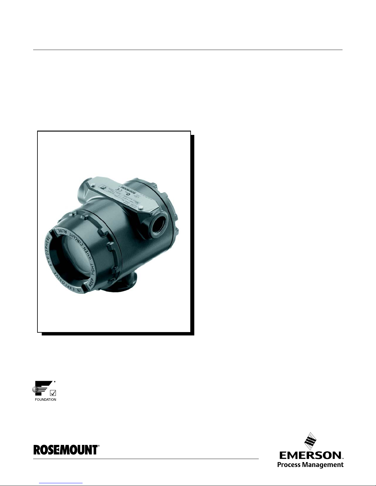
Rosemount 752 Remote Indicator
with FOUNDATION™ fieldbus protocol
www.rosemount.com
Page 2

Page 3

Reference Manual
NOTICE
00809-0100-4377, Rev BA
September 2010
Rosemount 752
Rosemount 752 Remote
Indicator with F
OUNDATION
™
fieldbus protocol
Read this manual before working with the product. For personal and system safety, and for
optimum product performance, make sure you thoroughly understand the contents before
installing, using, or maintaining this product.
Within the United States, Rosemount Inc. has two toll-free assistance numbers:
Customer Central
Technical support, quoting, and order-related questions.
1-800-999-9307 (7:00 am to 7:00 pm CST)
North American Response Center
Equipment service needs.
1-800-654-7768 (24 hours—includes Canada)
Outside of the United States, contact your local Emerson Process Management
representative.
The products described in this document are NOT designed for nuclear-qualified
applications. Using non-nuclear qualified products in applications that require
nuclear-qualified hardware or products may cause inaccurate readings.
For information on Rosemount nuclear-qualified products, contact your local Emerson
Process Management Sales Representative.
www.rosemount.com
Page 4

Page 5

Reference Manual
00809-0100-4377, Rev BA
September 2010
Rosemount 752
Table of Contents
SECTION 1
Introduction
SECTION 2
Configuration
Overview . . . . . . . . . . . . . . . . . . . . . . . . . . . . . . . . . . . . . . . . . . . . . . . 1-1
Using This Manual. . . . . . . . . . . . . . . . . . . . . . . . . . . . . . . . . . . . . . . . 1-1
Service Support . . . . . . . . . . . . . . . . . . . . . . . . . . . . . . . . . . . . . . . 1-2
Device Description. . . . . . . . . . . . . . . . . . . . . . . . . . . . . . . . . . . . . . . . 1-2
Node Address . . . . . . . . . . . . . . . . . . . . . . . . . . . . . . . . . . . . . . . . . . . 1-2
Foundation fieldbus function blocks. . . . . . . . . . . . . . . . . . . . . . . . . . . 1-3
Overview . . . . . . . . . . . . . . . . . . . . . . . . . . . . . . . . . . . . . . . . . . . . . . . 2-1
Safety Messages. . . . . . . . . . . . . . . . . . . . . . . . . . . . . . . . . . . . . . . . . 2-1
Warnings . . . . . . . . . . . . . . . . . . . . . . . . . . . . . . . . . . . . . . . . . . . . 2-1
Installation of the Rosemount 752. . . . . . . . . . . . . . . . . . . . . . . . . . . . 2-2
Set Switches. . . . . . . . . . . . . . . . . . . . . . . . . . . . . . . . . . . . . . . . . . 2-2
Connect Wiring and Power Up . . . . . . . . . . . . . . . . . . . . . . . . . . . . 2-3
General Considerations. . . . . . . . . . . . . . . . . . . . . . . . . . . . . . . . . . . . 2-5
Tagging. . . . . . . . . . . . . . . . . . . . . . . . . . . . . . . . . . . . . . . . . . . . . . 2-5
Hazardous Locations. . . . . . . . . . . . . . . . . . . . . . . . . . . . . . . . . . . . . . 2-6
Grounding the Indicator Case. . . . . . . . . . . . . . . . . . . . . . . . . . . . . 2-6
General Block Information. . . . . . . . . . . . . . . . . . . . . . . . . . . . . . . . . . 2-7
Modes. . . . . . . . . . . . . . . . . . . . . . . . . . . . . . . . . . . . . . . . . . . . . . . 2-7
Link Active Scheduler. . . . . . . . . . . . . . . . . . . . . . . . . . . . . . . . . . . 2-8
Block Instantiation . . . . . . . . . . . . . . . . . . . . . . . . . . . . . . . . . . . . . 2-8
Capabilities. . . . . . . . . . . . . . . . . . . . . . . . . . . . . . . . . . . . . . . . . . . 2-9
Resource Block . . . . . . . . . . . . . . . . . . . . . . . . . . . . . . . . . . . . . . . . . . 2-9
FEATURES and FEATURES_SEL . . . . . . . . . . . . . . . . . . . . . . . . 2-9
MAX_NOTIFY. . . . . . . . . . . . . . . . . . . . . . . . . . . . . . . . . . . . . . . . 2-10
PlantWeb
LCD Transducer Block. . . . . . . . . . . . . . . . . . . . . . . . . . . . . . . . . . . . 2-13
Custom Meter Configuration. . . . . . . . . . . . . . . . . . . . . . . . . . . . . 2-14
™
Alarms. . . . . . . . . . . . . . . . . . . . . . . . . . . . . . . . . . . . 2-11
SECTION 3
Operation and
Maintenance
SECTION 4
Troubleshooting
www.rosemount.com
Overview . . . . . . . . . . . . . . . . . . . . . . . . . . . . . . . . . . . . . . . . . . . . . . . 3-1
Safety Messages. . . . . . . . . . . . . . . . . . . . . . . . . . . . . . . . . . . . . . . . . 3-2
Warnings . . . . . . . . . . . . . . . . . . . . . . . . . . . . . . . . . . . . . . . . . . . 3-2
Resource Block . . . . . . . . . . . . . . . . . . . . . . . . . . . . . . . . . . . . . . . . . . 3-2
Master Reset Method. . . . . . . . . . . . . . . . . . . . . . . . . . . . . . . . . . . 3-2
Software Upgrade in the Field . . . . . . . . . . . . . . . . . . . . . . . . . . . . . . . 3-2
Overview . . . . . . . . . . . . . . . . . . . . . . . . . . . . . . . . . . . . . . . . . . . . . . . 4-1
Safety Messages. . . . . . . . . . . . . . . . . . . . . . . . . . . . . . . . . . . . . . . . . 4-1
Warnings . . . . . . . . . . . . . . . . . . . . . . . . . . . . . . . . . . . . . . . . . . . . 4-1
Troubleshooting Guides. . . . . . . . . . . . . . . . . . . . . . . . . . . . . . . . . . . . 4-2
Resource Block . . . . . . . . . . . . . . . . . . . . . . . . . . . . . . . . . . . . . . . . . . 4-5
LCD Transducer block. . . . . . . . . . . . . . . . . . . . . . . . . . . . . . . . . . . . . 4-6
Page 6

Rosemount 752
Reference Manual
00809-0100-4377, Rev BA
September 2010
APPENDIX A
Reference Information
APPENDIX B
Product Certificates
APPENDIX C
Block Information
Specifications. . . . . . . . . . . . . . . . . . . . . . . . . . . . . . . . . . . . . . . . . . . .A-1
Functional Specifications . . . . . . . . . . . . . . . . . . . . . . . . . . . . . . . .A-1
Performance Specifications . . . . . . . . . . . . . . . . . . . . . . . . . . . . . .A-1
Physical Specifications. . . . . . . . . . . . . . . . . . . . . . . . . . . . . . . . . .A-1
Dimensional Drawings. . . . . . . . . . . . . . . . . . . . . . . . . . . . . . . . . . . . .A-2
Ordering Information . . . . . . . . . . . . . . . . . . . . . . . . . . . . . . . . . . . . . .A-3
Approved Manufacturing Locations. . . . . . . . . . . . . . . . . . . . . . . . . . .B-1
European Directive Information . . . . . . . . . . . . . . . . . . . . . . . . . . .B-1
Hazardous Locations Certifications. . . . . . . . . . . . . . . . . . . . . . . . . . .B-1
North American Certifications. . . . . . . . . . . . . . . . . . . . . . . . . . . . .B-1
Canadian Standards Association (CSA). . . . . . . . . . . . . . . . . . . . .B-2
European Certifications . . . . . . . . . . . . . . . . . . . . . . . . . . . . . . . . .B-2
IECEx Certifications. . . . . . . . . . . . . . . . . . . . . . . . . . . . . . . . . . . . . . .B-4
Approval Drawings. . . . . . . . . . . . . . . . . . . . . . . . . . . . . . . . . . . . . . . .B-5
Resource Block . . . . . . . . . . . . . . . . . . . . . . . . . . . . . . . . . . . . . . . . . .C-1
Parameters and Descriptions. . . . . . . . . . . . . . . . . . . . . . . . . . . . .C-1
LCD Transducer Block. . . . . . . . . . . . . . . . . . . . . . . . . . . . . . . . . . . . .C-7
TOC-2
Page 7

Reference Manual
00809-0100-4377, Rev BA
September 2010
Rosemount 752
Section 1 Introduction
OVERVIEW This manual was developed with the assumption that the user will have a
basic understanding of F
Information is available at www.plantweb.emersonprocess.com/university or
check with your system integrator about resources for your specific host
system.
USING THIS MANUAL The sections in this manual provide information on configuring,
troubleshooting, operating and maintaining the Rosemount 752 Remote
Indicator with F
The sections in this manual are organized as follows:
• Section 2: Configuration provides instruction on configuration of the
Rosemount 752 Remote Indicator with F
Information on software functions, configuration parameters, and other
variables are also included.
• Section 3: Operation and Maintenance contains operation and
maintenance techniques.
• Section 4: Troubleshooting provides troubleshooting techniques for
the most common operating problems.
• Appendix A: Reference Information supplies reference and
specification data, as well as ordering information.
• Appendix B: Product Certificates contains intrinsic safety approval
information, European ATEX directive information, and approval.
• Appendix C: Block Information supplies reference block information
such as parameter tables.
OUNDATION fieldbus protocol.
OUNDATION Fieldbus concepts and wiring practices.
OUNDATION fieldbus protocol.
www.rosemount.com
Page 8
Reference Manual
00809-0100-4377, Rev BA
Rosemount 752
September 2010
Service Support To expedite the return process outside of the United States, contact the
nearest Rosemount representative.
Within the United St ates, call the Rosemount National Response Cen ter using
the 1-800-654-RSMT (7768) toll-free number. This center, available 24 hours
a day, will assist you with any needed information or materials.
The center will ask for product model and serial numbers, and will provide a
Return Material Authorization (RMA) number. The center will also ask for the
process material to which the product was last exposed.
Individuals who handle products exposed to a hazardous substance can avoid injury if
they are informed of and understand the hazard. If the product being returned was
exposed to a hazardous substance as defined by OSHA, a copy of the required Material
Safety Data Sheet (MSDS) for each hazardous substance identified must be included
with the returned goods.
Rosemount National Response Center representatives will explain the
additional information and procedures necessary to return goods exposed to
hazardous substances.
DEVICE DESCRIPTION Before configuring the device, ensure the host has the appropriate Device
Description file revision for this device. The device descriptor can be found on
www.rosemount.com.
NODE ADDRESS The indicator is shipped at a temporary (248) address. This will enable
OUNDATION fieldbus host systems to automatically recognize the device and
F
move it to a permanent address.
1-2
Page 9

Reference Manual
00809-0100-4377, Rev BA
September 2010
Rosemount 752
FOUNDATION FIELDBUS
FUNCTION BLOCKS
For reference information on the LCD Transducer and Advanced Diagnostics
Transducer blocks refer to “Fou ndation Fieldbus Block Information” on
page A-1. Reference information on the ISEL, INT, ARTH, SGCR and PID
blocks can be found in the Function Block manual document number
00809-0100-4783.
Resource Block (1000)
The Resource block contains diagnostic, hardware and electronics
information. There are no linkable inputs or outputs to the Resource Block.
LCD Transducer Block (1100)
The LCD Transducer Block is used to configure the LCD meter.
PID Block (1200)
The PID Function Block combines all of the necessary logic to perform
proportional/integral/derivative (PID) control. The block supports mode
control, signal scaling and limiting, feed forward control, override tracking,
alarm limit detection, and signal status propagation.
The block supports two forms of the PID equation: Standard and Series. You
can choose the appropriate equation using the MATHFORM parameter. The
Standard ISA PID equation is the default selection.
Input Selector Block (1300)
The Input Selector (ISEL) Function Block can be used to select the first good,
Hot Backup, maximum, minimum, or average of as many as eight input
values and place it at the output. The block supports signal status
propagation.
Signal Characterizer Block (1400)
The Signal Characterizer (SGCR) Function Block characterizes or
approximates any function that defines an input/output relationship. The
function is defined by configuring as many as twenty X,Y coordinates. The
block interpolates an output value for a given input value using the curve
defined by the configured coordinates. Two separate analog input signals can
be processed simultaneously to give two corresponding separate output
values using the same defined curve.
Arithmetic Block (1500)
The Arithmetic (ARTH) Function Block provides the ability to configure a
range extension function for a primary input. It can also be used to compute
nine different arithmetic functions.
Integrator Block (1600)
The Integrator (INT) Function Block integrates one or two variables over time.
The block compares the integrated or accumulated value to pre-trip and trip
limits and generates discrete output signals when the limits are reached.
1-3
Page 10

Rosemount 752
Reference Manual
00809-0100-4377, Rev BA
September 2010
1-4
Page 11
Reference Manual
00809-0100-4377, Rev BA
September 2010
Rosemount 752
Section 2 Configuration
Overview . . . . . . . . . . . . . . . . . . . . . . . . . . . . . . . . . . . . . . . page 2-1
Safety Messages . . . . . . . . . . . . . . . . . . . . . . . . . . . . . . . . . page 2-1
General Considerations . . . . . . . . . . . . . . . . . . . . . . . . . . . page 2-5
Connect Wiring and Power Up . . . . . . . . . . . . . . . . . . . . . page 2-3
Hazardous Locations . . . . . . . . . . . . . . . . . . . . . . . . . . . . . page 2-6
General Block Information . . . . . . . . . . . . . . . . . . . . . . . . .page 2-7
Resource Block . . . . . . . . . . . . . . . . . . . . . . . . . . . . . . . . . . page 2-9
LCD Transducer Block . . . . . . . . . . . . . . . . . . . . . . . . . . . . page 2-13
OVERVIEW This section covers basic operation, software functionality, and basic
configuration procedures for the Rosemount 752 Remote Indicator with
OUNDATION fieldbus protocol. This section is organized by block information.
F
For detailed information about the function blocks used in the Rosemount 752
Remote Indicator, refer to “Block Information” on page C-1 and the
Foundation fieldbus Block manual (00809-0100-4783).
SAFETY MESSAGES Procedures and instructions in this section may require special precautions to
ensure the safety of the personnel performing the operations. Information that
raises potential safety issues is indicated by a warning symbol ( ). Refer to
the following safety messages before performing an operation preceded by
this symbol.
Warnings
Explosions can result in death or serious injury.
• Do not remove the indicator covers in explosive environments when the circuit
is live.
• Indicator covers must be fully engaged to meet explosion proof requirements.
• Before connecting a configuration tool in an explosive atmosphere, make sure
the instruments in the loop are installed in accordance with intrinsically safe or
nonincendive field wiring practices.
Electrical shock can result in death or serious injury.
• Avoid contact with the leads and terminals. High voltage that may be present
on leads can cause electrical shock.
www.rosemount.com
Page 12

Rosemount 752
Security
Alarm/Simulate
INSTALLATION OF THE
ROSEMOUNT 752
Set Switches Security (Write Protect)
Changes can be prevented to the indicator configuration data with the write
protection PlantWeb housing switches. Security is controlled by the security
(write protect) switch/jumper located on the interface assembly or terminal
block. Position the switch/jumper in the “ON” position to prevent accide ntal or
deliberate change of configuration data.
If the indicator write protection switch/jumper is in the “ON” position, the
indicator will not accept any “writes” to its memory. Configuration changes
cannot take place when the indicator security is on.
To reposition the switches/jumpers, follow the procedure described
below. (Simulate = fieldbus protocol)
1. Set the loop to manual and remove power.
2. Remove the electronics compartment cover, opposite the field terminal
side on the PlantWeb housing. Do not remove the indicator covers in
explosive atmospheres when the circuit is live.
3. Slide the security and simulate switches into the preferred position by
using a small screwdriver.
Reference Manual
00809-0100-4377, Rev BA
September 2010
Figure 2-1. PlantWeb Housing
Switches
Re-install the indicator cover. Indicator covers must be fully engaged to meet
explosion-proof requirements.
2-2
Page 13
Reference Manual
See “Safety Messages” on page 2-1 for complete warning information.
00809-0100-4377, Rev BA
September 2010
Rosemount 752
Connect Wiring and
Power Up
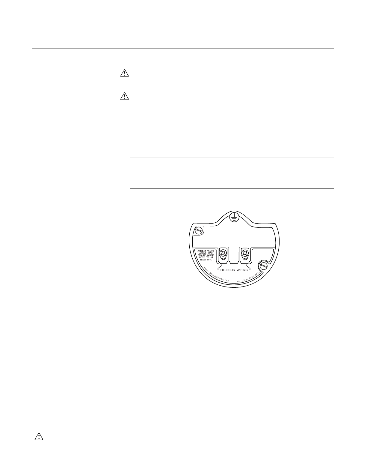
Figure 2-2. Fieldbus terminal
block
Wiring for fieldbus protocol
1. Remove the housing cover on terminal compartment side. Do not
remove the cover in explosive atmospheres when the circuit is live.
Signal wiring supplies all power to the indicator.
2. Connect the power leads to the terminals marked “FIELDBUS WIRING”
as shown in Figure 2 -2 . Th e power te rm in als ar e no t po lar ity se nsitive.
3. Plug and seal unused conduit connec tions on the indic at or hous ing to
avoid moisture accumulation in the terminal side. If you do not seal
unused connections, mount the indicator with the electrical housing
positioned downward for drainage. Install wiring with a drip loop . Arrange
the drip loop so the bottom is lower than the conduit connections and the
indicator housing.
NOTE
Do not apply high voltage (e.g. ac line voltage) to the indicator terminals.
Abnormally high voltage can damage the unit. (Indicator power terminals are
rated to 32 V dc).
Electrical Considerations
Proper electrical installation is necessary to prevent errors due to improper
grounding and electrical noise. Shielded, twisted pair cable should be
used for best results in electrically noisy environments. Cable Type A is
recommended by F
Power Supply
The indicator requires between 9 and 32 V dc (9 and 15 V dc for FISCO) to
operate and provide complete functionality. The dc power supply should
provide power with less than 2% ripple.
Power Conditioner
A fieldbus segment requires a power conditione r to isolate the power
supply filter and decouple the segment from othe r seg m en ts attached to
the same power supply.
Grounding
Signal wiring of the fieldbus segment can not be grounded. Ground ing out
one of the signal wires will shut down the entire fieldbus segment.
OUNDATION
®
fieldbus.
2-3
Page 14
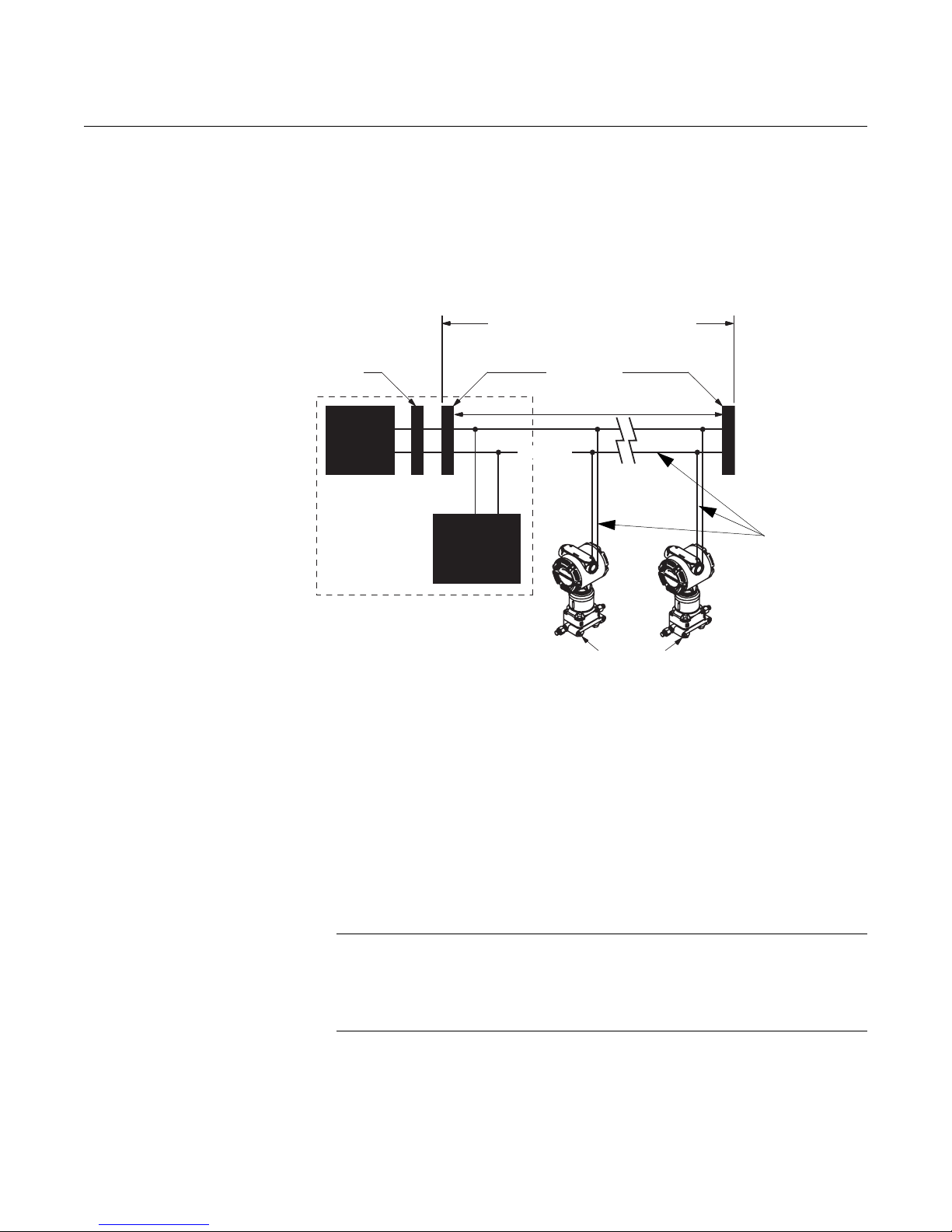
Rosemount 752
Power
Supply
F
OUNDATION
fieldbus
Configuration
Tool
Terminators
Integrated Power
Conditioner
and Filter
(Trunk)
(Spur)
(Spur)
(The power supply, filter, first
terminator, and configuration tool are
typically located in the control room.)
Signal
Wiring
Fieldbus
Segment
6234 ft (1900 m) max
(depending upon cable
characteristics)
*Intrinsically safe installations may allow fewer devices per I.S. barrier due to current limitations.
fieldbus
devices on
segment
Figure 2-3. Fieldbus indicator
field wiring
Reference Manual
00809-0100-4377, Rev BA
September 2010
Shield Wire Ground
To protect the fieldbus segment from noise, grounding techniques for
shield wire usually require a single grounding point for shield wire to avoid
creating a ground loop. The ground point is typically at the power supply.
Surges/Transients
The indicator will withstand electrical transients of the energy level usually
encountered in static discharges or induced switching transients. However ,
high-energy transients, such as those induced in wiring from nearby
lightning strikes, can damage the indicator.
Optional Transient Protection Terminal Block
The transient protection terminal block can be ordered as an installed
option (Option Code T1 in the indicator model number) or as a spare part.
The spare part number is 03151-4134-0002. The lightning bolt symbol
shown identifies it as a transient protection terminal block.
NOTE
The fieldbus physical layer specification requires indicator communication
during extreme operating conditions of 250 V
transient terminal block was designed to limit common mode voltages to 90 V
and cannot be used in these extreme operating conditions.
2-4
common mode signal. The
rms
Page 15

Reference Manual
COMMISSIONING TAG
Device ID:
00XXXXXXXX010001440-121698091725
PD Tag:
PT- 101
Revision: 7.2
Support files available at
www.rosemount.com
Revision: 7.2
Support files available at
www.rosemount.com
Device Serial Number:
XXXXXXXXXX
Device ID:
00XXXXX010001440-121698091725
PD Tag:
PT- 101
Tear He re
00809-0100-4377, Rev BA
September 2010
Rosemount 752
GENERAL
CONSIDERATIONS
Tagging Commissioning (Paper) Tag on a fieldbus segment
When commissioning more than one device on a fieldbus segment, it can be
difficult to identify which device is at a particular location. A removable tag
provided with the indicator can aid in this process by linking the Device ID and
a physical location. The Device ID is a unique code that identifies a particular
device in the absence of a device tag. The device t ag is us ed by the customer
as an operational identification for the device and is usually defined by the
Piping and Instrumentation Diagram (P & ID).
The installer should note the physical location in both places on the
removable commissioning tag and tear off the bottom portion. This should be
done for each device on the segment. The bottom portion of the tags can be
used for commissioning the segment in the control system, providing a direct
link between the Device ID and the tag location.
2-5
Page 16

Rosemount 752
Reference Manual
00809-0100-4377, Rev BA
September 2010
HAZARDOUS
LOCATIONS
Grounding the
Indicator Case
The 752 Remote Indicator has explosion-proof housing and circuitry suitable
for intrinsically safe and non-incendive operation. Individual indicators are
clearly marked with a tag indicating the certifications they carry. See
Appendix B: Product Certificates for installation drawings.
NOTE
Once a device labeled with multiple approvals is installed, it should not be
reinstalled using any other approval type(s). Permanently mark the
certification label to distinguish the installed approval type from unused
approval types.
Always ground the indicator case in accordance with national and local
electrical codes. The most effective indicator case grounding method is a
direct connection to earth ground with minimal impedance. Methods for
grounding the indicator case include:
• Internal Ground Connection: The Internal Ground Connection screw
is inside the terminal side of the electronics housing. The screw is
identified by a ground symbol ( ), and is standard on the 752 Remote
Indicators.
• External Ground Assembly: Ground screw is located at the bottom of
the mounting bracket.
NOTE
Grounding the indicator case using the threaded conduit connection may not
provide a sufficient ground. The transient protection terminal block (Option
Code T1) will not provide transient protection unless the indicator case is
properly grounded. Use the above guidelines to ground the indicator case. Do
not run transient protection ground wire with signal wiring; the ground wire
may carry excessive current if a lightning strike occurs.
2-6
Page 17

Reference Manual
Resource
Block
Transducer
Block
Analog Input
(AI Block)
Other
function
blocks
00809-0100-4377, Rev BA
September 2010
Rosemount 752
GENERAL BLOCK
INFORMATION
Modes The Resource, Transducer, and all function blocks in the device have modes
of operation. These modes govern the operation of the block. Every block
supports both automatic (AUTO) and out of service (OOS) modes. Othe r
modes may also be supported.
Changing Modes
To change the operating mode, set the MODE_BLK.TARGET to the desired
mode. After a short delay, the parameter MODE_BLOCK.ACTUAL should
reflect the mode change if the block is operating properly.
Permitted Modes
It is possible to prevent unauthorized changes to the operating mode of a
block. To do this, configure MODE_BLOCK.PERMITTED to allow only the
desired operating modes. It is recommended to always select OOS as one of
the permitted modes.
Types of Modes
For the procedures described in this manual, it will be helpful to understand
the following modes:
AUTO
The functions performed by the block will execute. If the block has any
outputs, these will continue to update. This is typically the normal
operating mode.
Out of Service (OOS)
The functions performed by the block will not execute. If the block has any
outputs, these will typically not update and the status of any values passed
to downstream blocks will be “BAD”. To make some changes to the
configuration of the block, change the mode of the block to OOS. When
the changes are complete, change the mode back to AUTO.
MAN
In this mode, variables that are passed out of the block can be manually
set for testing or override purposes.
Other Types of Modes
Other types of modes are Cas, RCas, ROut, IMan and LO. Some of these
may be supported by different function blocks in the 752. For more
information, see the Function Block manual, document 00809-0100- 4783.
NOTE
When an upstream block is set to OOS, this will impact the output status of all
downstream blocks. The figure below depicts the hierarchy of blocks:
2-7
Page 18

Reference Manual
00809-0100-4377, Rev BA
Rosemount 752
September 2010
Link Active Scheduler The 752 can be designated to act as the backup Link Active Scheduler (LAS)
in the event that the LAS is disconnected from the segment. As the backup
LAS, the 752 will take over the management of communications until the host
is restored.
The host system may provide a configuration tool specifically designed to
designate a particular device as a backup LAS. Otherwise, this can be
configured manually as follows:
1. Access the Management Information Base (MIB) for the 752.
2. To activate the LAS capability, write 0x02 to the
BOOT_OPERAT_FUNCTIONAL_CLASS object (Index 605). To
deactivate, write 0x01.
3. Restart the processor.
Block Instantiation Rosemount devices are pre-configured with function blocks at the factory, the
default permanent configuration for the Rosemount 752 is listed below. The
Rosemount 752 can have up to nine additional instantiated function blocks.
• 1 Proportional/Integral/Derivative Block (tag name PID_1600)
• 1 Input Selector Block (tag name ISEL_1700)
• 1 Signal Characterizer Block (tag name CHAR_1800)
• 1 Arithmetic Block (tag name ARITH_1900)
• 1 Integrator Block (tag name INTEG_2000)
The Rosemount 752 supports the use of Function Block In stantiation. When a
device supports block instantiation, the number o f blocks and block types can
be defined to match specific application needs.The number of blocks that can
be instantiated is only limited by the amount of memor y within the device and
the block types that are supported by the device. Instantiation does not apply
to standard device blocks like the Resource and LCD Transducer Block.
By reading the parameter “FREE_SPACE” in the Resource block you can
determine how many blocks you can instantiate. Each block that you
instantiate takes up 4.5573% of the “FREE_SPACE”.
Block instantiation is done by the host control system or configuration tool, but
not all hosts are required to implement this functionality. Please refer to your
specific host or configuration tool manual for more information.
2-8
Page 19

Reference Manual
00809-0100-4377, Rev BA
September 2010
Capabilities Virtual Communication Relationship (VCRs)
There are a total of 20 VCRs. One is permanent a nd 1 9 are fu lly config ur able
by the host system. Thirty link objects are available.
Network Parameter Value
Slot Time 6
Maximum Response Delay 4
Maximum Inactivity to Claim LAS Delay 60
Minimum Inter DLPDU Delay 7
Time Sync class 4 (1ms)
Maximum Scheduling Overhead 21
Per CLPDU PhL Overhead 4
Maximum Inter-channel Signal Skew 0
Required Number of Post-transmission-gab-ext Units 0
Required Number of Preamble-extension Units 1
Host timer recommendations
T1 = 96000
T2 = 1920000
T3 = 480000
Rosemount 752
RESOURCE BLOCK
FEATURES and
FEATURES_SEL
Block Execution times
PID = 10 ms
Arithmetic = 10 ms
Input Selection = 10 ms
Signal Characterizer = 10 ms
Integrator = 10 ms
The parameters FEATURES and FEATURE_SEL determine optional
behavior of the Rosemount 752.
FEATURES
The FEATURES parameter is read only and defines which features are
supported by the Rosemount 752. Below is a list of the FEATURES the 752
supports.
UNICODE
All configurable string variables in the Rosemount 752, except tag names, are
octet strings. Either ASCII or Unicode may be used. If the configuration device
is generating Unicode octet strings, you must set the Unicode option bit.
REPORTS
The Rosemount 752 supports alert reports. The Reports option bit must be
set in the features bit string to use this feature. If it is not set, the host must
poll for alerts.
2-9
Page 20

Rosemount 752
Reference Manual
00809-0100-4377, Rev BA
September 2010
SOFT W LOCK and HARD W LOCK
Inputs to the security and write lock functions include the hardware security
switch, the hardware and software write lock bits of the FEATURE_SEL
parameter, the WRITE_LOCK parameter, and the DEFINE_WRITE_LOCK
parameter.
The WRITE_LOCK parameter prevents modification of parameters within the
device except to clear the WRITE_LOCK parameter. During this time, the
block will function normally updating inputs and outputs and executing
algorithms. When the WRITE_LOCK condition is cleared, a WRITE_ALM
alert is generated with a priority that correspond s to the WRI TE _PR I
parameter.
The FEATURE_SEL parameter enables the user to select a hardware or
software write lock or no write lock capability. T o ena ble the hardwar e security
function, enable the HW_SEL bit in the FEA TURE_SEL p arameter. When this
bit has been enabled the WRITE_LOCK parameter becomes read only and
will reflect the state of the hardware switch. In order to enable the software
write lock, the SW_SEL bit must be set in the FEATURE_SEL parameter.
Once this bit is set, the WRITE_LOCK parameter may be set to “Locke d ” or
“Not Locked.” Once the WRITE_LOCK parameter is set to “Locked” by either
the software or the hardware lock, all user requested writes as determined by
the DEFINE_WRITE_LOCK parameter shall be rejected.
The DEFINE_WRITE_LOCK parameter allows the user to configure whether
the write lock functions (both software and hardware) will control writing to all
blocks, or only to the resource and transducer blocks. Interna lly updated dat a
such as process variables and diagnostics will not be restricted by the
security switch.
The following table displays all possible configurations of the WRITE_LOCK
parameter.
FEATURE_SEL
HW_SEL bit
0 (off) 0 (off) NA 1 (unlocked) Read only NA All
0 (off) 1 (on) NA 1 (unlocked) Read/Write NA All
0 (off) 1 (on) NA 2 (lo cked) Read/Write Physical Function
0 (off) 1 (on) NA 2 (lo cked) Read/Write Everything None
1 (on) 0 (off)
1 (on) 0 (off) 1 (locked) 2 (locked) Read only Physical Function
1 (on) 0 (off) 1 (locked) 2 (locked) Read only Everything None
(1) The hardware and software write lock select bits are mutually exclusive and the hardwar e select ha s the hi ghest prio rity. When the HW_SEL bit if set to 1
(on), the SW_SEL bit is automatically set to 0 (off) and is read only.
FEATURE_SEL
SW_SEL bit
(1)
WRITE_LOCK
SECURITY SWITCH WRITE_LOCK
0 (unlocked) 1 (unlocked) Read only NA All
Read/Write
DEFINE_WRITE_LOCK
Write access
to blocks
Blocks only
Blocks only
FEATURES_SEL
FEA TURES_SEL is used to turn on any of the supported featur es. The default
setting of the Rosemount 752 does not select any of these features. Choose
one of the supported features if any.
MAX_NOTIFY The MAX_NOTIFY parameter value is the maximum number of alert repor ts
2-10
that the resource can have sent without getting a confirmation, corresponding
to the amount of buffer space available for alert messages. The number can
be set lower, to control alert flooding, by adjusting the LIM_NOTIFY
parameter value. If LIM_NOTIFY is set to zero, then no alerts are reported.
Page 21

Reference Manual
00809-0100-4377, Rev BA
September 2010
Rosemount 752
PlantWeb™ Alarms The alarms and recommended actions should be used in conjunction with
Section 2: Troubleshooting.
The Resource Block will act as a coordinator for PlantWeb alarms. There will
be three alarm parameters (FAILED_ALARM, MAINT_ALARM, and
ADVISE_ALARM) which will contain information regarding some of the device
errors which are detected by the indicator software. There will be a
RECOMMENDED_ACTION parameter which will be used to display the
recommended action text for the highest priority alarm. FAILED_ALARM will
have the highest priority followed by MAINT_ALARM and ADVISE_ALARM
will be the lowest priority.
FAILED_ALARMS
A failure alarm indicates a failure within a device that will make the device or
some part of the device non-operational. This implies that the device is in
need of repair and must be fixed immediately. There are five parameters
associated with FAILED_ALARMS specifically, they are described below.
FAILED_ENABLED
This parameter contains a list of failures in the device which makes the
device non-operational that will cause an alarm to be sent. Below is a list
of the failures with the highest priority first.
1. Circuit Board Memory Failure
2. General Circuit Board Memory Failure
3. Lost Deferred Data
FAILED_MASK
This parameter will mask any of the failed conditions listed in
FAILED_ENABLED. A bit on means that the condition is masked out from
alarming and will not be reported.
FAILED_PRI
Designates the alarming priority of the FAILED_ALM, see “ADVISE_PRI”
on page 2-12. The default is 0 and the recommended value are between 8
and 15.
FAILED_ACTIVE
This parameter displays which of the alarms is active. Only the alarm with
the highest priority will be displayed. This priority is not the same as the
FAILED_PRI p arameter described above. This p riority is hard coded within
the device and is not user configurable.
FAILED_ALM
Alarm indicating a failure within a device which makes the device
non-operational.
MAINT_ALARMS
A maintenance alarm indicates the device or some part of the device needs
maintenance soon. If the condition is ignored, the device will eventually fail.
There are five parameters associated with MAINT_ALARMS, they are
described below.
2-11
Page 22

Rosemount 752
Reference Manual
00809-0100-4377, Rev BA
September 2010
MAINT_ENABLED
The MAINT_ENABLED parameter contains a list of conditions indicating
the device or some part of the device needs maintenance soon. If the
condition is ignored, the device will eventually fail.
MAINT_MASK
The MAINT_MASK parameter will mask any of the failed conditions listed
in MAINT_ENABLED. A bit on means that the condition is masked out
from alarming and will not be reported.
MAINT_PRI
MAINT_PRI designates the alarming priority of the MA INT_ ALM ,
“MAINT_ALM” on page 2- 12 . Th e de fa u lt is 0 and the re co mm e nde d
values is 3 to 7.
MAINT_ACTIVE
The MAINT_ACTIVE parameter displays which of the alarms is active.
Only the condition with the highest priority will be displayed. This priority is
not the same as the MAINT_PRI parameter described above. This priority
is hard coded within the device and is not user configurable.
MAINT_ALM
An alarm indicating the device needs maintenance soon. If the co ndition is
ignored, the device will eventually fail.
Advisory Alarms
An advisory alarm indicates informative conditions that do not have a direct
impact on the device's primary functions There are five parameters
associated with ADVISE_ALARMS, they are described below.
ADVISE_ENABLED
The ADVISE_ENABLED parameter contains a list of informative
conditions that do not have a direct impact on the device's primary
functions.
• Alert Simulation Enabled
• LOI Failure
• Local Display Failure
• NV Writes Deferred
ADVISE_MASK
The ADVISE_MASK parameter wi ll mask any of the failed conditions listed
in ADVISE_ENABLED. A bit on means the condition is masked out from
alarming and will not be reported.
ADVISE_PRI
ADVISE_PRI designates the alarming priority of the ADVISE_ALM, see
“ADVISE_PRI” on page 2-12. The default is 0 and the recommended
values are 1 or 2.
2-12
ADVISE_ACTIVE
The ADVISE_ACTIVE parameter displays which of the advisories is
active. Only the advisory with the highest priority will be displayed. This
priority is not the same as the ADVISE_PRI parameter described above.
This priority is hard coded within the device and is not user configurable.
Page 23
Reference Manual
00809-0100-4377, Rev BA
September 2010
Table 2-1.
RB.RECOMMENDED_ACTION
Rosemount 752
ADVISE_ALM
ADVISE_ALM is an alarm indicating advisory alarms. These conditions do
not have a direct impact on the process or device integrity.
Recommended Actions for PlantWeb Alarms
RECOMMENDED_ACTION
The RECOMMENDED_ACTION parameter displays a text string that will
give a recommended course of action to take based on which type and
which specific event of the PlantWeb alarms is active.
Failed/Maint/Advise Active Event Recommended Action Text String
None No action required
LOI Failure Check Display connections and Sensor
connections
NV Writes Deferred
Alert Simulation Enabled Disable Simulate Switch before returninig device
to service
NV Memory Failure Reset the device then download the device
configuration
RB Electronics Failure Replace the fieldbus electronics board
LCD TRANSDUCER
BLOCK
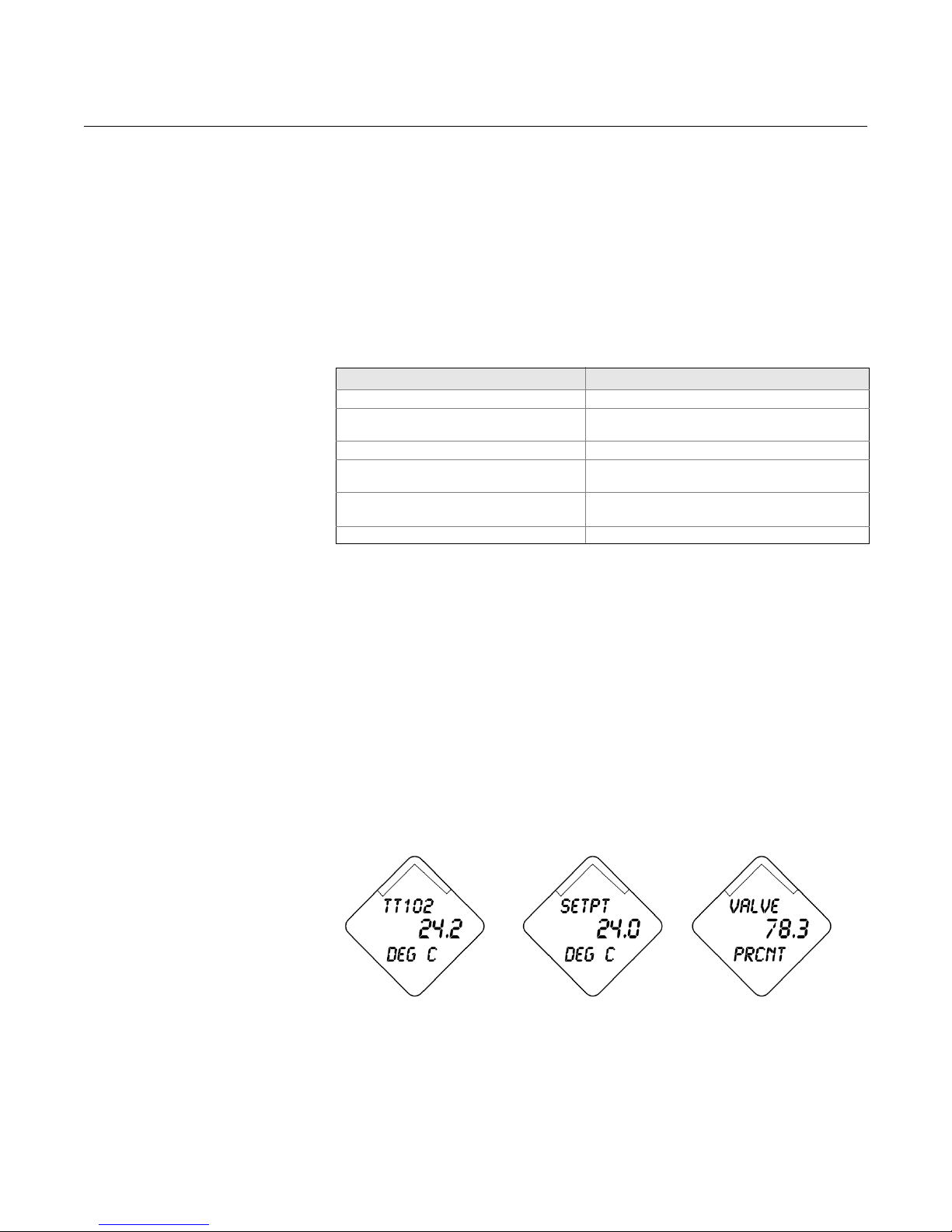
Figure 2-4. LCD Messaging
The LCD meter connects directly to the Rosemount 752 electronics
OUNDATION fieldbus output board. The meter indicates output and
F
abbreviated diagnostic messages.
The meter features a four-line display and alarm. The 0-100% scaled bar
graph is not used in the Rosemount 752. The first line of five characters
displays the output description, the second line of seven digits displays the
actual value, the third line of six characters displays engineering units and the
fourth line displays “Error” when the indicator is in alarm. The LCD meter can
also display diagnostic messages.
Each parameter configured for display will appear on the LCD for a brief
period before the next parameter is displayed. If the status of the parameter
goes bad, the LCD will also cycle diagnostics following the displayed variable:
2-13
Page 24

Rosemount 752
Reference Manual
00809-0100-4377, Rev BA
September 2010
Custom Meter
Configuration
To configure parameters 1 – 8, use the configuration parameters below.
The LCD Transducer Block can be configured to sequence eight different
process variables.
The output from blocks in other devices on the segment can be linked to one
of the inputs of the ISEL block and then displayed on the LCD. The LCD
would then be configured to display the Block Tag of the ISEL block and the
input parameter.
DISPLAY_PARAM_SEL
The DISPLAY_PARAM_SEL parameter specifies how many process
variables will be displayed. Select up to eight display parameters.
BLK_TAG_#
(1)
Enter the Block Tag of the function block that contains the parameter to be
displayed. The default function block tags from the factory are:
PID_1200
ISEL_1300
CHAR_1400
ARITH_1500
INTEG_1600
BLK_TYPE_#
(1)
Enter the Block Type of the function block that contains the parameter to be
displayed. This parameter is generally selected via a drop-down menu with a
list of possible function block types. (e.g. ISEL PID, etc.)
PARAM_INDEX_#
(1)
The PARAM_INDEX_# parameter is generally selected via a drop-down
menu with a list of possible parameter names base d upon wh at is available in
the function block type selected. Choose the parameter to be displayed.
CUSTOM_TAG_#
(1)
The CUSTOM_TAG_# is an optional user-specified tag identifier that can be
configured to be displayed with the parameter in place of the blo ck tag. Enter
a tag of up to five characters.
UNITS_TYPE_#
(1)
The UNITS_TYPE_# parameter is generally selected via a drop-down menu
with three options: AUTO, CUSTOM, or NONE. Select AUTO only when the
parameter to be displayed is pressure, temperature, or percent. For other
parameters, select CUSTOM and be sure to configure the
CUSTOM_UNITS_# parameter. Select NONE if the parameter is to be
displayed without associated units.
CUSTOM_UNITS_#
(1)
Specify custom units to be displayed with the parameter. Enter up to six
characters. To display Custom Units the UNITS_TYPE_# must be set to
CUSTOM.
(1) _# represents the specified parameter number.
2-14
Page 25
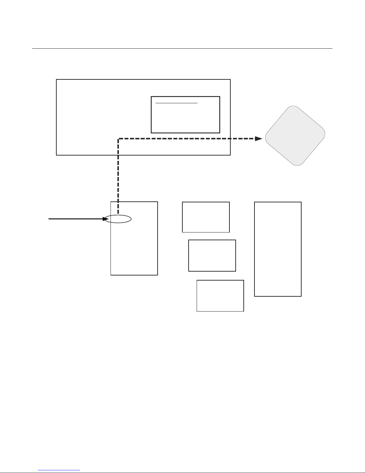
Reference Manual
PID
LCD
Configuration Block
TT102
71.2
DEG C
Characterizer
DISPLAY_PARAM_SEL = n n= 1 - 8
For each value displayed:
BLK_TAG_n
BLK_TYPE_n
PARAM_INDEX_n
CUSTOM_TAG_n
UNITS_TYPE_n
CUSTOM_UNITS_n
Arithmetic
Input Selector
TAG= ISEL 1300
IN_1
IN_2
IN_3
IN_4
IN_5
IN_6
IN_7
IN_8
OUT
Example: Display Value #1
BLK_TAG_1 = ISEL 1300
BLK_TYPE_1 = Input Selector
PARAM_INDEX_1 = IN_1
CUSTOM_TAG_1 = TT102
UNITS_TYPE_1 = CUSTOM
CUSTOM_UNITS_1 = DEG C
Linked from AI Block in
Temperature Transmtter TT102
IN_1
IN_2
IN_3
IN_4
IN_1
IN_2
Integrator
IN_1
IN_2
OUT
OUT
OUT
OUT_1
OUT_1
PV
SP
IN
CAS_IN
BKCAL_OUT
BKCAL_IN
RCAS_IN
ROUT_IN
RCAS_OUT
ROUT_OUT
TRK_VAL
FF_VAL
00809-0100-4377, Rev BA
September 2010
Figure 2-5. Configuring the LCD
to Display Data from a Different
Device on the Fieldbus Segment
Rosemount 752
2-15
Page 26

Rosemount 752
Reference Manual
00809-0100-4377, Rev BA
September 2010
2-16
Page 27

Reference Manual
00809-0100-4377, Rev BA
September 2010
Rosemount 752
Section 3 Operation and Maintenance
Overview . . . . . . . . . . . . . . . . . . . . . . . . . . . . . . . . . . . . . . . page 3-1
Safety Messages . . . . . . . . . . . . . . . . . . . . . . . . . . . . . . . . . page 3-2
Resource Block . . . . . . . . . . . . . . . . . . . . . . . . . . . . . . . . . . page 3-2
Software Upgrade in the Field . . . . . . . . . . . . . . . . . . . . . .page 3-2
OVERVIEW This section contains information on operation and maintenance procedures.
METHODS AND MANUAL OPERATION
Each F
displaying and performing operations. Some hosts will use Device
Descriptions (DD) and DD Methods to complete device configuration and will
display data consistently across platforms. The DD can found on
www.rosemount.com. There is no requirement that a host or configuration tool
support these features.
OUNDATION fieldbus host or configuration tool has different ways of
The information in this section will describe how to use methods in a general
fashion. In addition, if your host or configuration tool does not support
methods this section will cover manually configuring the parameters involved
with each method operation. For more detailed information on the use of
methods, see your host or configuration tool manual.
www.rosemount.com
Page 28
Reference Manual
00809-0100-4377, Rev BA
Rosemount 752
September 2010
SAFETY MESSAGES Procedures and instructions in this section may require special precautions to
ensure the safety of the personnel performing the operations. Information that
raises potential safety issues is indicated by a warning symbol ( ). Refer to
the following safety messages before performing an operation preceded by
this symbol.
Warnings
Explosions can result in death or serious injury.
• Do not remove the indicator covers in explosive environments when the circuit is
live.
• Indicators covers must be fully engaged to meet explosion proof requirements.
• Before connecting a communicator in an explosive atmosphere, make su re the
instruments in the loop are installed in accordance with intrinsically safe or
nonincendive field wiring practices.
RESOURCE BLOCK
Master Reset Method
Electrical shock can result in death or serious injury.
• Avoid contact with the leads and terminals. High voltage that may be present on
leads can cause electrical shock.
Performing a 'Restart with defaults' will set all function block information in the device to
factory defaults. This includes the clearing of all function block links and schedule, as well
as defaulting all Resource and Transducer Block user data (Advanced Diagnostic Block
algorithm configurations, LCD Transducer Block parameter configuration, etc.).
To perform a master reset, run the Master Reset Method. If your system does
not support methods, manually configure the Resource Block parameters
listed below.
1. Set the RESTART to one of the options below:
• Set Run to nominal state when not restarting (default)
• Resource is not used by device”
• Defaults set all device parameters to F
OUNDATION fieldbus default
values
• The Processor does a software reset of the CPU
SOFTWARE UPGRADE
IN THE FIELD
3-2
Software for the 752 with FOUNDATION fieldbus is easy to upgrade in the field
using the F
OUNDATION fieldbus Common Device Software Download
procedure.
Page 29
Reference Manual
00809-0100-4377, Rev BA
September 2010
Rosemount 752
Section 4 Troubleshooting
Overview . . . . . . . . . . . . . . . . . . . . . . . . . . . . . . . . . . . . . . . page 4-1
Safety Messages . . . . . . . . . . . . . . . . . . . . . . . . . . . . . . . . . page 4-1
Troubleshooting Guides . . . . . . . . . . . . . . . . . . . . . . . . . .page 4-2
Resource Block . . . . . . . . . . . . . . . . . . . . . . . . . . . . . . . . . . page 4-5
LCD Transducer block . . . . . . . . . . . . . . . . . . . . . . . . . . . .page 4-6
OVERVIEW This section provides summarized troubleshooting suggestions for the mo st
common operating problems. This section contains Rosemount 752 fieldbus
troubleshooting information only.
Follow the procedures described here to verify that indicator hardware and
process connections are in good working or der. Always deal with the most
likely checkpoints first.
SAFETY MESSAGES Procedures and instructions in this section may require special precautions to
ensure the safety of the personnel performing the operations. Information that
raises potential safety issues is indicated by a warning symbol ( ). Refer to
the following safety messages before performing an operation preceded by
this symbol.
Warnings
Explosions can result in death or serious injury.
• Do not remove the indicator covers in explosive environments when the circuit
is live.
• Indicator covers must be fully engaged to meet explosion proof requirements.
• Before connecting a communicator in an explosive atmosphere, make sure
that the instruments in the loop are installed according to intrinsically safe or
nonincendive field wiring practices.
Static electricity can damage sensitive components.
• Observe safe handling precautions for static-sensitive components.
www.rosemount.com
Page 30
Rosemount 752
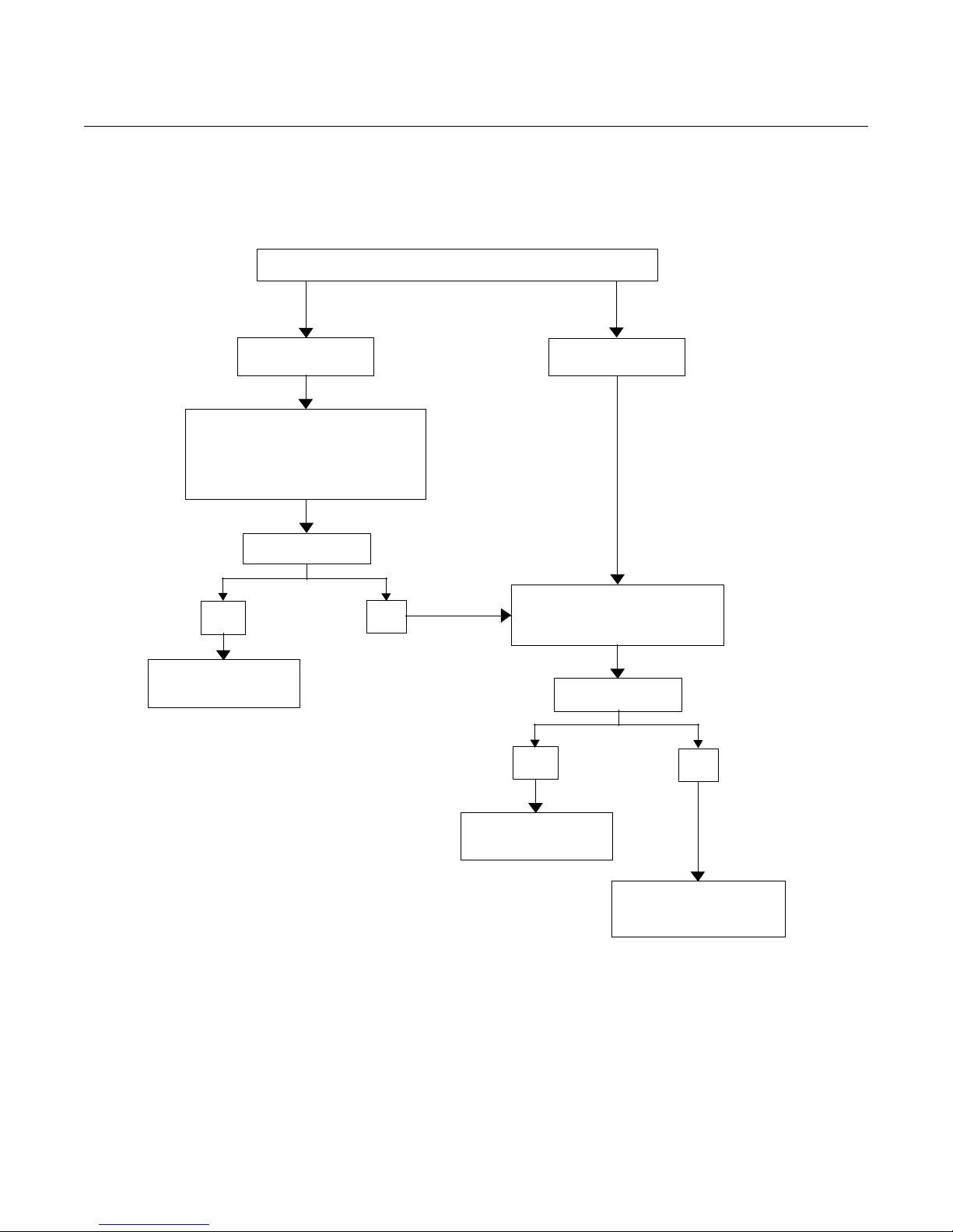
PROBLEMS WITH COMMUNICATIONS
Device does not
appear on segment.
1. Check wiring to device.
2. Recycle power to device.
3. Electronic failure.
Refer to “Device does not show up on
segment” in Table 4-1 for more
information.
Problem Identified?
Yes
No
Perform Recommended
Action, see Table 4-1.
Check Segment, see “Device
does not stay on segment” in
Table4-1 for more information.
Problem Identified?
Yes
No
Perform Recommended
Action, see page 2-6.
If the problem persists
contact your local
Rosemount representative.
Device does not
stay on segment.
TR OUBLESHOOTING
GUIDES
Figure 4-1. Rosemount 752
troubleshooting flowchart
Reference Manual
00809-0100-4377, Rev BA
September 2010
4-2
Page 31
Reference Manual
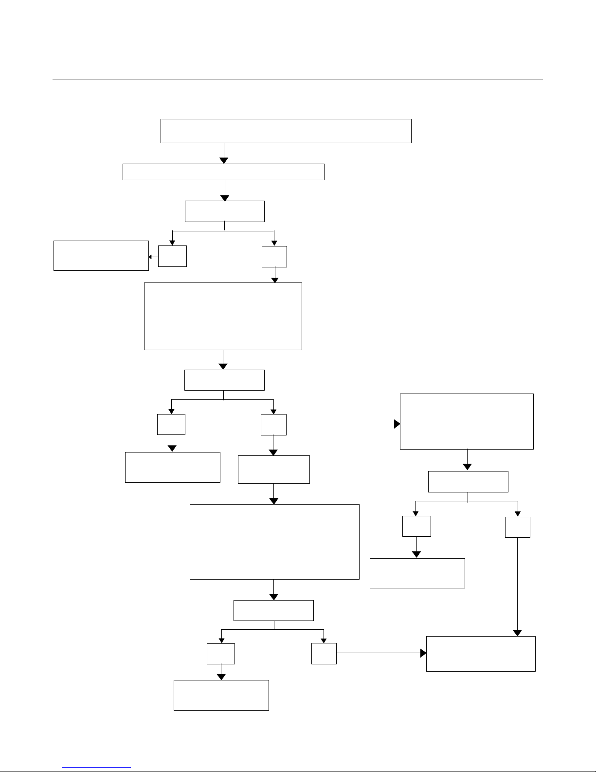
COMMUNICATIONS ESTABLISHED BUT HAVE
“BLOCK_ERR” OR AN “ALARM” CONDITION.
See “PlantWeb™ Alarms" on page 2-11
Read the following parameters in the
Resource Block to determine the
recommended action.
BLOCK_ERR (see Table 4-2)
SUMMARY_STATUS (see Table 4-3)
DETAILED_STATUS (see Table 4-4)
Problem Identified?
Yes
No
Perform Recommended
Action, see Table 4-4.
For more detailed
information
Perform the following steps in the LCD
Transducer Block to determine the
recommended action.
BLOCK_ERR (see page 4-5)
If error condition does not exist
in the Resource Block then it is a
configuration problem, see
“Block Errors” in Table 4-2
Problem Identified?
Yes
No
If the problem persists
contact your local
Rosemount representative.
Problem Identified?
Perform Recommended
Action
Yes
No
Perform Recommended
Action
Yes
No
Perform Recommended
Action, see Table 2-1.
Problem Identified?
00809-0100-4377, Rev BA
September 2010
Figure 4-2. Problems with
communications flowchart
Rosemount 752
4-3
Page 32
00809-0100-4377, Rev BA
Rosemount 752
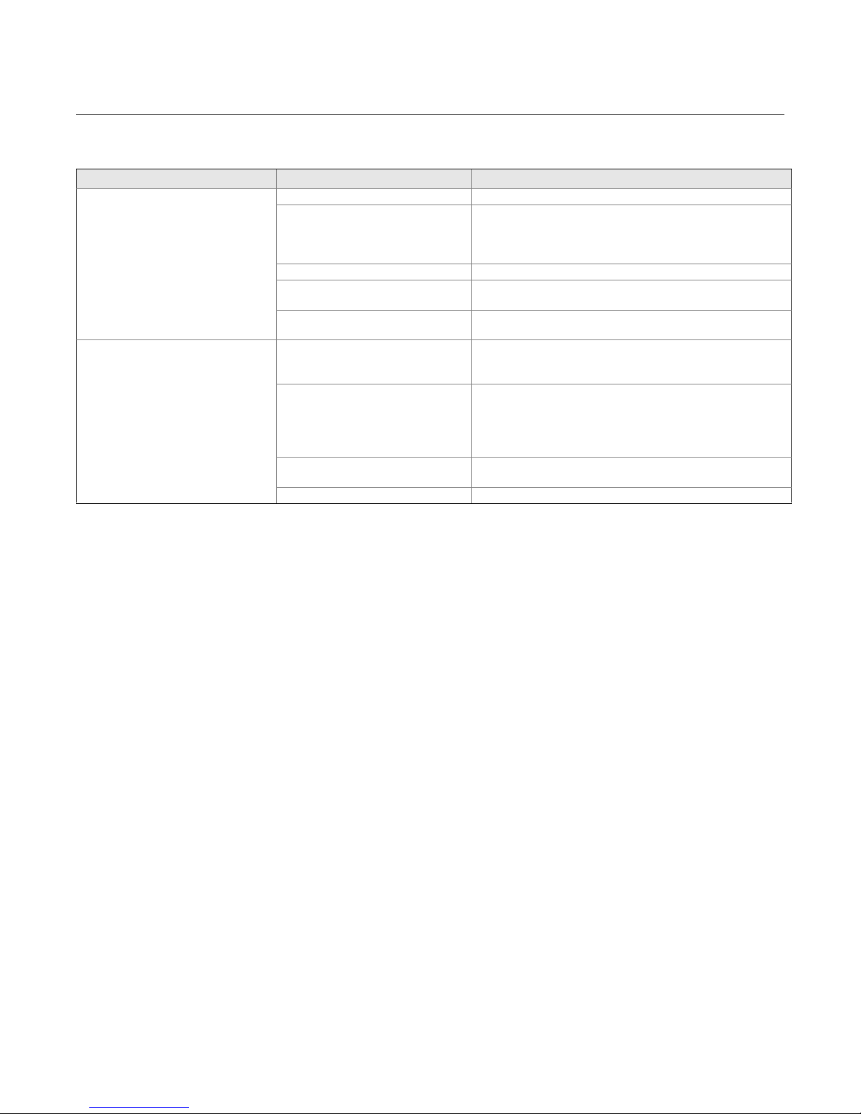
Table 4-1. Troubleshooting
guide.
Symptom
Device does not show up on segment Unknown Recycle power to device
Device does not stay on segment
(1) The corrective actions should be done with consultation of your system integrator.
(2) Wiring and installation 31.25 kbit/s, voltage mode, wire medium application guide AG-140 available from the fieldbus Foundation.
(1)
Cause Recommended Actions
No power to device 1. Ensure the device is connected to the segment.
Segment problems
Electronics failing 1. Electronics board loose in housing.
Incompatible network settings Change host network parameters.
(2)
Incorrect signal levels.
Refer to host documentation for
procedure.
Excess noise on segment.
Refer to host documentation for
procedure.
Electronics failing 1. Tighten electronics board.
Other 1. Check for water in the terminal housing.
2. Check voltage at terminals. There should be 9–32Vdc.
3. Check to ensure the device is drawing current. There should
be approximately 17 mA.
2. Replace electronics.
Refer to host documentation for procedure.
1. Check for two terminators.
2. Excess cable length.
3. Bad Power supply or conditioner
1. Check for incorrect grounding.
2. Check for correct shielded wire.
3. Tighten wire connections.
4. Check for corrosion or moisture on terminals.
5. Check for Bad power supply.
2. Replace electronics.
Reference Manual
September 2010
4-4
Page 33
Reference Manual
00809-0100-4377, Rev BA
September 2010
Rosemount 752
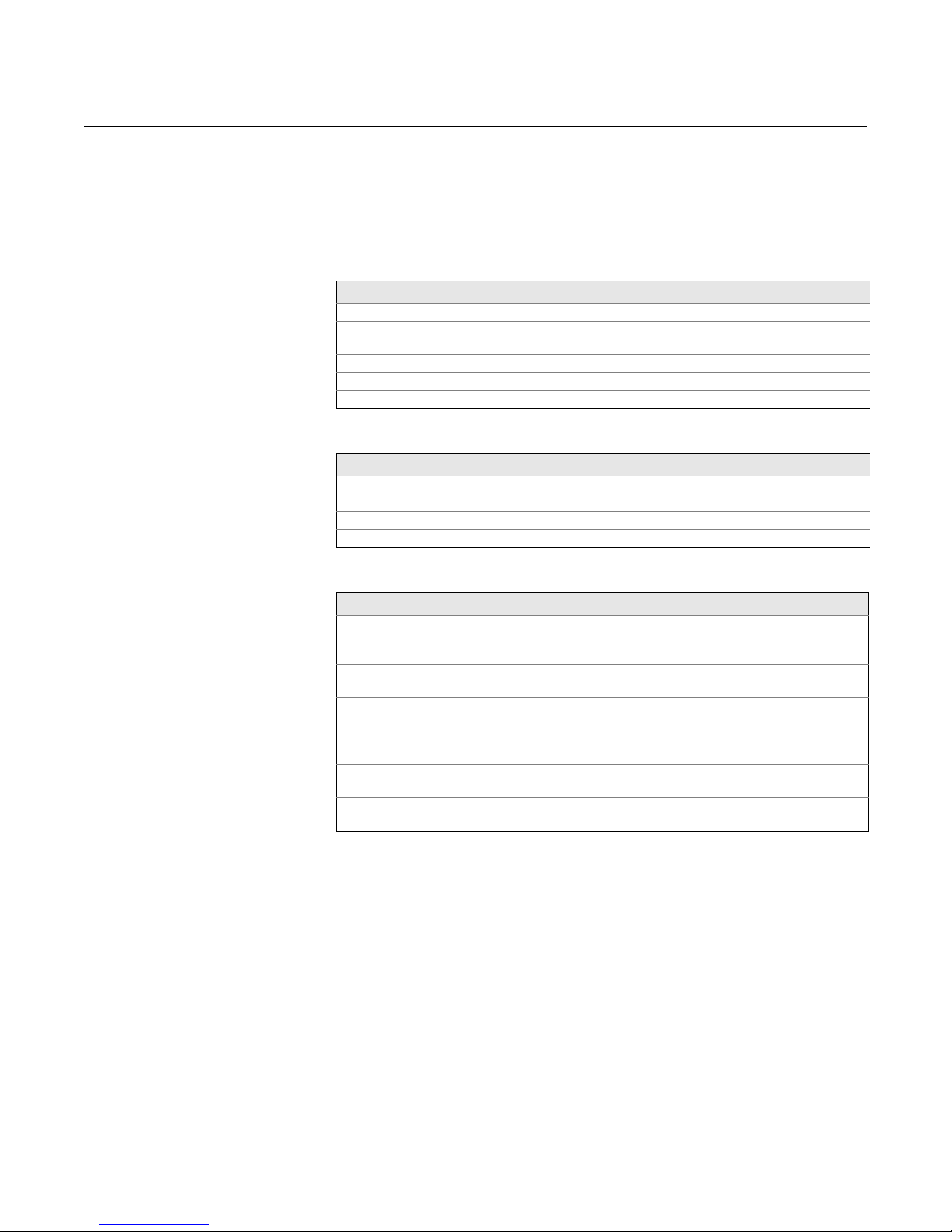
RESOURCE BLOCK This section describes error conditions found in the Resource block. Read
Table 4-2 through Table 4-4 to determine the appropriate corrective action.
Table 4-2. Resource Block
BLOCK_ERR messages
Table 4-3. Resource Block
SUMMARY_STATUS messages
Table 4-4. Resource Block
DETAILED_STATUS with
recommended action messages
Block Errors
Table 4-2 lists conditions reported in the BLOCK_ERR parameter.
Condition Name and Description
Other
Simulate Active: This indicates that the simulation switch is in place. This is not an indication
that the I/O blocks are using simulated data.
Memory Failure: A memory failure has occurred in FLASH, RAM, or EEPROM memory
Device Needs Maintenance Now
Out of Service: The actual mode is out of service.
Condition Name
Uninitilized
No repair needed
Repairable
Call Service Center
Condition Name Recommended Action
LOI Transducer block error 1. Restart processor
2. Check display connection
3. Call service center
Mfg. Block integrity error 1. Restart processor
2. Call service center
Non-Volatile memory integrity error 1. Restart processor
2.Call service center
ROM integrity error 1. Restart processor
2. Call service center
Lost Deferred NV Data 1. Restart processor
2. Call service center
NV writes deferred (warning) 1. Restart processor
2. Call service center
4-5
Page 34
Rosemount 752
Reference Manual
00809-0100-4377, Rev BA
September 2010
LCD TRANSDUCER
BLOCK
Table 4-5. LCD Transducer
Block BLOCK_ERR messages
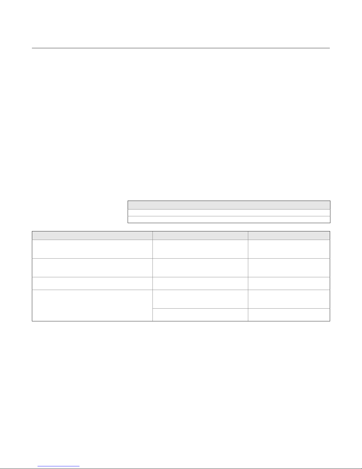
This section describes error conditions found in the LCD Transducer Block.
Read Table 4-5 and to determine the appropriate corrective action.
Self Test Procedure for the LCD
The SELF_TEST parameter in the Resource block will test LCD segments.
When running, the segments of the display should light up for about five
seconds.
If your host system supports methods refer to your host documentation on
how to run the Self Test method. If your host system does not support
methods than you can run this test manually be following the steps be low.
1. Put Resource block into OOS (Out of Service).
2. Go to the parameter called SELF_TEST and write the value Self test
(0x2).
3. Observe the LCD screen when you are do ing this . All of the se gm e nts
should light up.
4. Put the Resource block back into AUTO.
Condition Name and Description
Other
Out of Service: The actual mode is out of service.
Symptom Possible Causes Recommended Action
The LCD displays “DSPLY#INVLID.” Read the
BLOCK_ERR and if it says “BLOCK
CONFIGURATION” perform the Recommended Action
“752” is being displayed or not all of the values are
being displayed.
The display reads OOS The resource and or the LCD Transducer
The display is hard to read. Some of the LCD segments may have
One or more of the display parameters are
not configured properly.
The LCD block parameter
“DISPLAY_PARAMETER_SELECT is not
properly configured.
block are OOS.
gone bad.
Device is out of the temperature limit for the
LCD. (-20 to 85 °C)
See “LCD Transducer Block" on
page 2-16.
See “LCD Transducer Block" on
page 2-16.
Verify that both blocks are in
“AUTO,”
See Self Test procedure above. If
some of the segment is bad, replace
the LCD.
Check ambient temperature of the
device.
4-6
Page 35

Reference Manual
00809-0100-4377, Rev BA
September 2010
Rosemount 752
Appendix A Reference Information
Specifications . . . . . . . . . . . . . . . . . . . . . . . . . . . . . . . . . . . page A-1
Dimensional Drawings . . . . . . . . . . . . . . . . . . . . . . . . . . . .page A-2
Ordering Information . . . . . . . . . . . . . . . . . . . . . . . . . . . . . page A-3
SPECIFICATIONS
Functional
Specifications
Performance
Specifications
Current Consumption
17.5mA
Power Requirements
External power required;
operates on 9.0 to 32.0 V dc terminal voltage
Temperature Limits
-4 to 185°F (-20 to 85°C)
Ambient Storage
-40 to 185°F (-40 to 85°C)
Humidity Limits
0 - 100% relative humidity
Electrical Connections
1
/2 - 14 NPT, G 1/2, and M20 x 1.5 (CM20) conduit
Configurable to display up to eight function block output values.
Display sequences through configured variables at 3 second intervals.
Block Execution Times
PID: 25 ms
Arithmetic: 20 ms
Input Selection: 20 ms
Signal Characterizer: 20 ms
Integrator: 20 ms
Physical Specifications Weight
www.rosemount.com
2.5 lb (1.1 kg)
Page 36
Rosemount 752
1.82
(46)
3.08
(78)
6.90
(175)
2.66
(67)
6.24
(159)
2.33
(59)
5.19
(132)
4.72
(120)
2.66
(67)
6.15
(156)
4.48
(114)
Dimensions are in inches (millimeters)
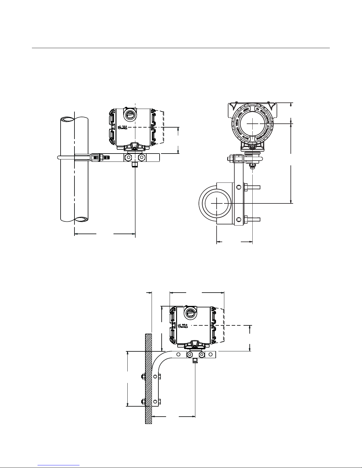
DIMENSIONAL
DRAWINGS
Figure A-1. Remote Pipe Mount
Meter Mounting Configurations
Reference Manual
00809-0100-4377, Rev BA
September 2010
Figure A-2. Remote Panel
Mount Meter Mounting
Configurations
A-2
Page 37
Reference Manual
00809-0100-4377, Rev BA
September 2010
Rosemount 752
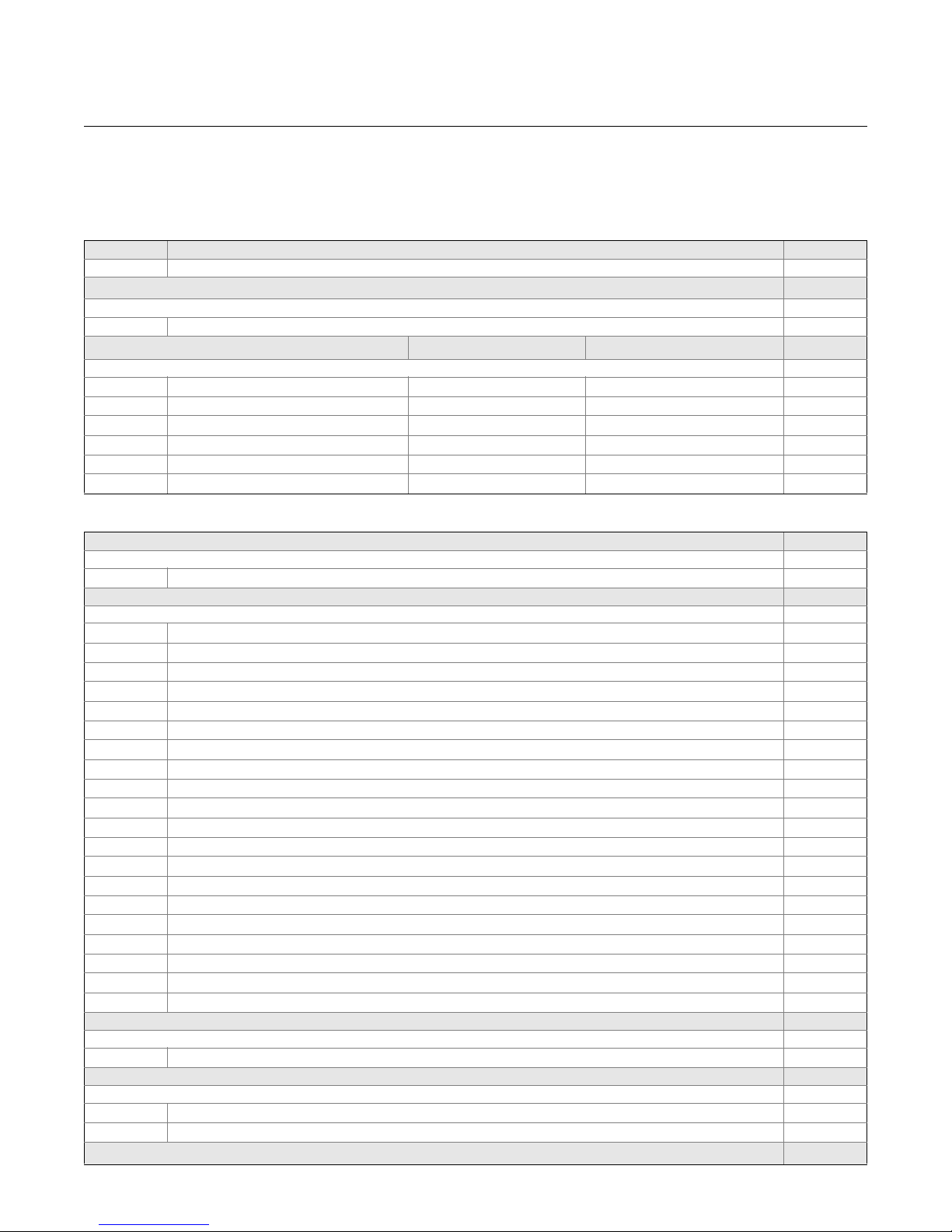
ORDERING INFORMATION
Table A-1. Rosemount 752 Fieldbus Remote Indicator Ordering Information
★ The Standard offering represents the most common options. The starred options (★) should be selected for best delivery.
__The Expanded offering is subject to additional delivery lead time.
Model Product Type
752 Fieldbus Remote Indicator
Transmitter Output
Standard Standard
F FOUNDATION fieldbus digital signal
Housing Style Material Conduit Entry Size
Standard Standard
1A PlantWeb Housing Aluminum
1B PlantWeb Housing Aluminum M20 x 1.5 (CM20)
1C PlantWeb Housing Aluminum JIS G1/2
1J PlantWeb Housing SST
1K PlantWeb Housing SST M20 x 1.5 (CM20)
1L PlantWeb Housing SST JIS G1/2
1
/2 - 14 NPT
1
/2-14 NPT
★
★
★
★
★
★
★
Options (Include with selected model number)
PlantWeb Control Functionality
Standard Standard
A01 FOUNDATION fieldbus Advanced Control Function Block Suite
Product Certifications
Standard Standard
E1 ATEX Flameproof
I1 ATEX Intrinsic Safety
IA ATEX FISCO Intrinsic Safety; for FOUNDATION fieldbus Protocol only
N1 ATEX Type n
K1 ATEX Flameproof, Intrinsic Safety, Type n, Dust (combination E1, I1, N1, and ND)
ND ATEX Dust
E5 FM Explosion-Proof, Dust-Ignition-proof
I5 FM Intrinsically Safe, Division 2
IE FM FISCO Intrinsically Safe; for FOUNDATION fieldbus protocol only
K5 FM Explosion-proof, Dust-Ignition-proof, Intrinsically Safe, Division 2 (combination E5 and I5)
E6 CSA Explosion-proof, Dust Ignition-proof, Division 2
I6 CSA Intrinsically Safe
IF CSA FISCO Intrinsically Safe; for FOUNDATION fieldbus protocol only
K6 CSA Explosion-proof, Dust-Ignition-proof, Intrinsically Safe, Division 2 (combination E6 and I6)
I7 IECEx Instrinsic Safety
N7 IECEx Type n
KA ATEX and CSA Flameproof, Intrinsically Safe, Division 2 (combination E1, E6, I1,and I6)
KB FM and CSA Explosion-proof, Dust Ignition-proof, Intrinsically Safe, Division 2 (E5, E6, I5, I6)
KC FM and ATEX Explosion-proof, Intrinsically Safe, Division 2 (combination of E5, E1, I5,and I1)
IG IECEx FISCO Intrinsically Safe; for FOUNDATION fieldbus protocol only
Transient Protection
Standard Standard
T1 Integral Transient Protector
Conduit Electrical Connector
Standard Standard
(1)
GE
GM
Typical Model Number: 752 F 1A A01 E1
(1) Not available with certain hazardous location certifications. Contact your local Emerson Process Management represent ative for details.
M12, 4-pin, Male Connector (eurofast®)
(1)
A size Mini, 4-pin, Male Connector (minifast®)
★
★
★
★
★
★
★
★
★
★
★
★
★
★
★
★
★
★
★
★
★
★
★
★
A-3
Page 38

Rosemount 752
Reference Manual
00809-0100-4377, Rev BA
September 2010
A-4
Page 39

Reference Manual
00809-0100-4377, Rev BA
September 2010
Appendix B Product Certificates
Approved Manufacturing Locations . . . . . . . . . . . . . . . . . page B-1
Hazardous Locations Certifications . . . . . . . . . . . . . . . . .page B-1
Approval Drawings . . . . . . . . . . . . . . . . . . . . . . . . . . . . . . .page B-5
Rosemount 752
APPROVED
MANUFACTURING
LOCATIONS
European Directive
Information
HAZARDOUS
LOCATIONS
CERTIFICATIONS
North American
Certifications
Rosemount Inc. — Chanhassen, Minnesota USA
Fisher-Rosemount GmbH & Co. — Wessling, Germany
Emerson Process Management Asia Pacific Private Limited — Singapore
Emerson Process Management LTDA — Sorocaba, Brazil
Emerson Process Management (India) Pvt. Ltd. — Daman, India
Emerson Process Management FZE — Jebel Ali Free Zone, Dubai
The EC declaration of conformity for all applicable European directives fo r this
product can be found on the Rosemount website at www.rosemount.com. A
hard copy may be obtained by contacting our local sales office.
Electro Magnetic Compatibility (EMC)
EN 61326-1:2006
ATEX Directive (94/9/EC)
Emerson Process Management complies with the ATEX Directive.
Factory Mutual (FM)
E5 Explosion-Proof for Class I, Division 1, Group s B, C, and D; dust- ignition
proof for Class II and Class III, Division 1, Group s E, F, and G; hazardous
locations;
enclosure Type 4X,
conduit seal not required.
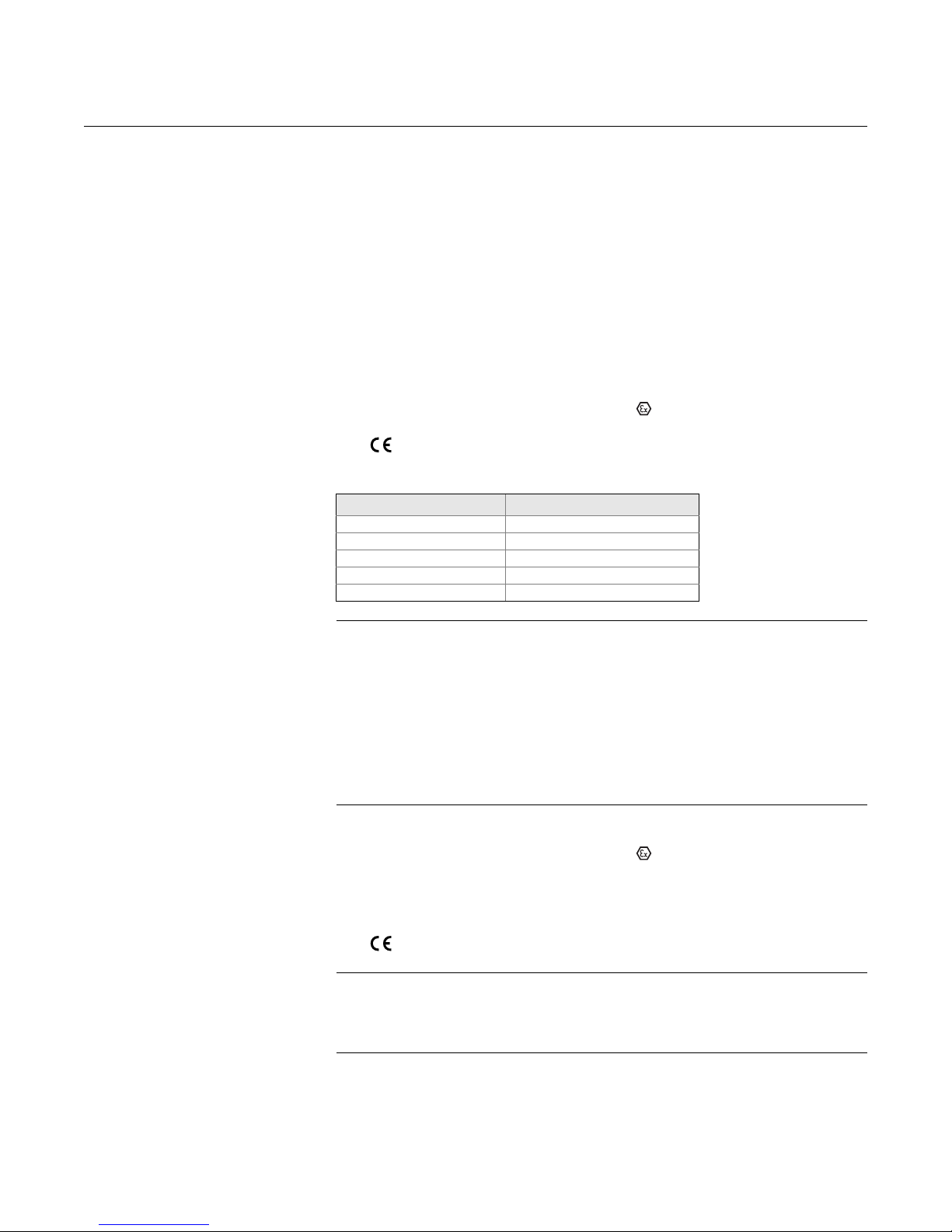
I5/IEIntrinsically Safe for use in Class I, Division 1,
Groups A, B, C, and D; Class II, Division 1,
Groups E, F, and G; Class III, Division 1 Class I, Zone 0, AEx ia IIC T4
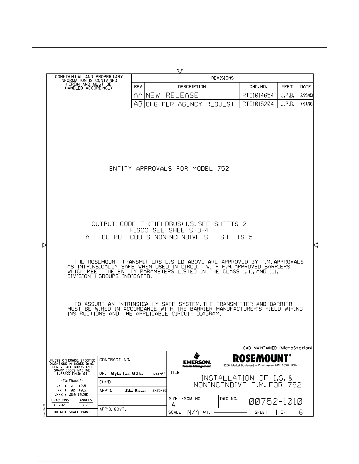
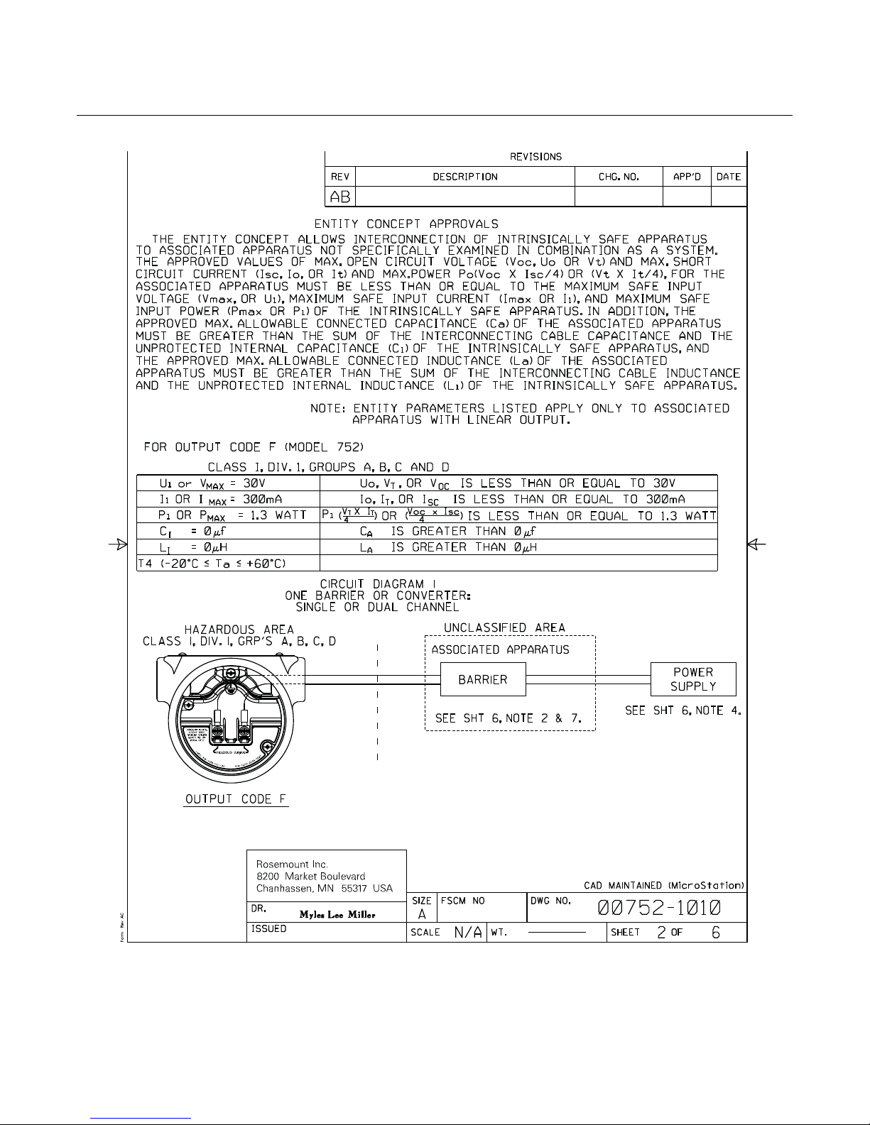
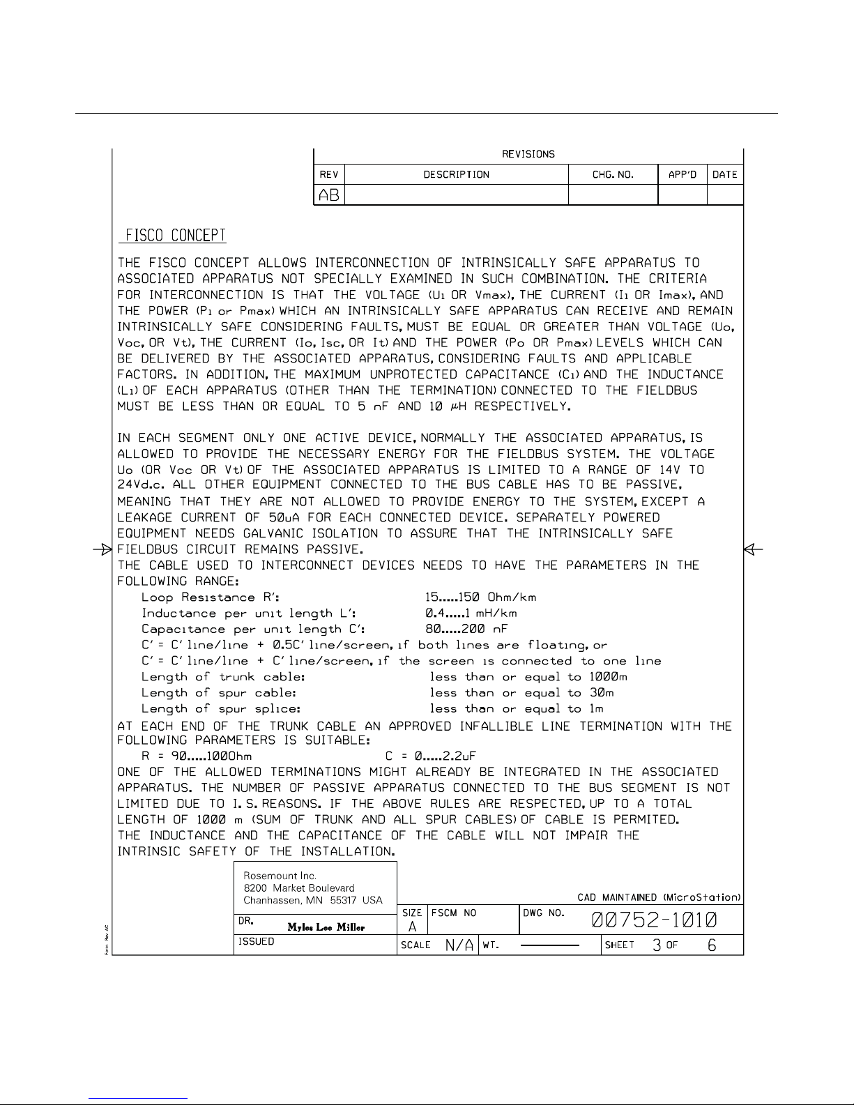
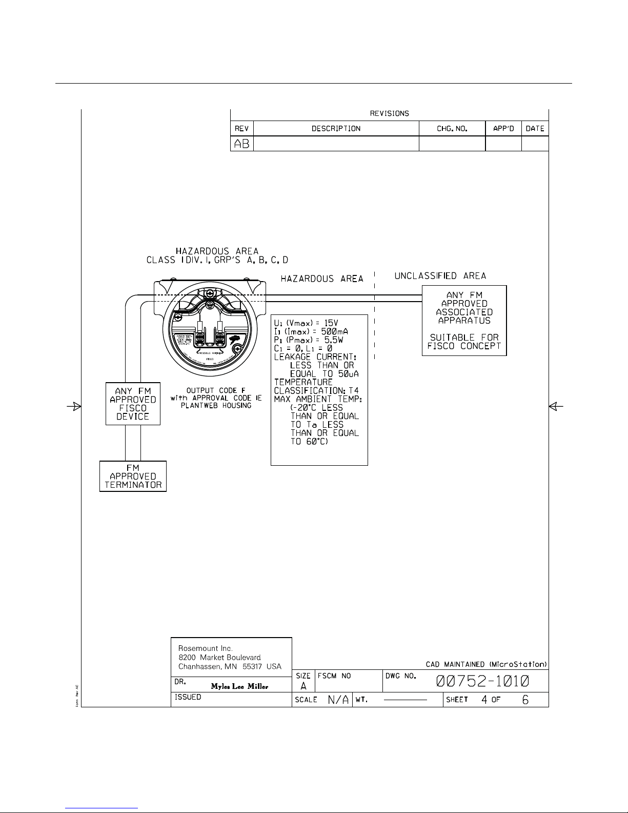
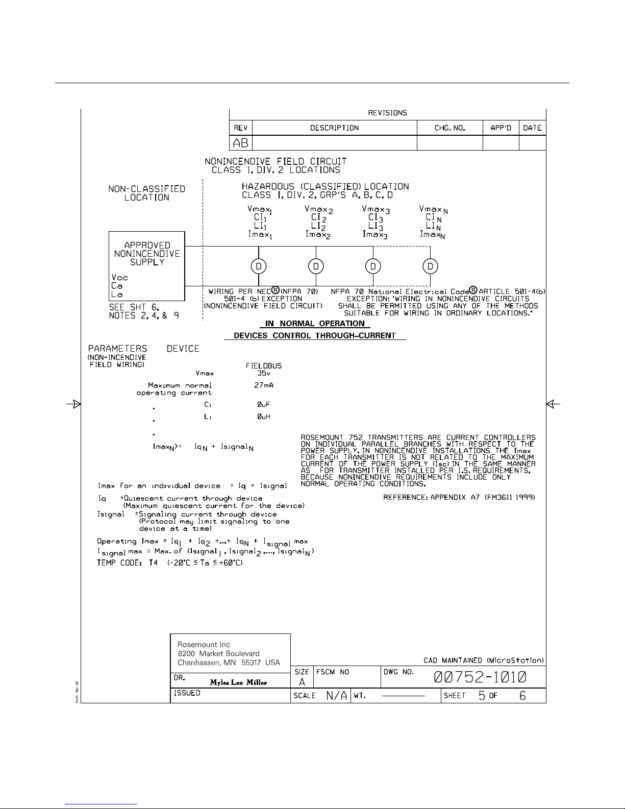
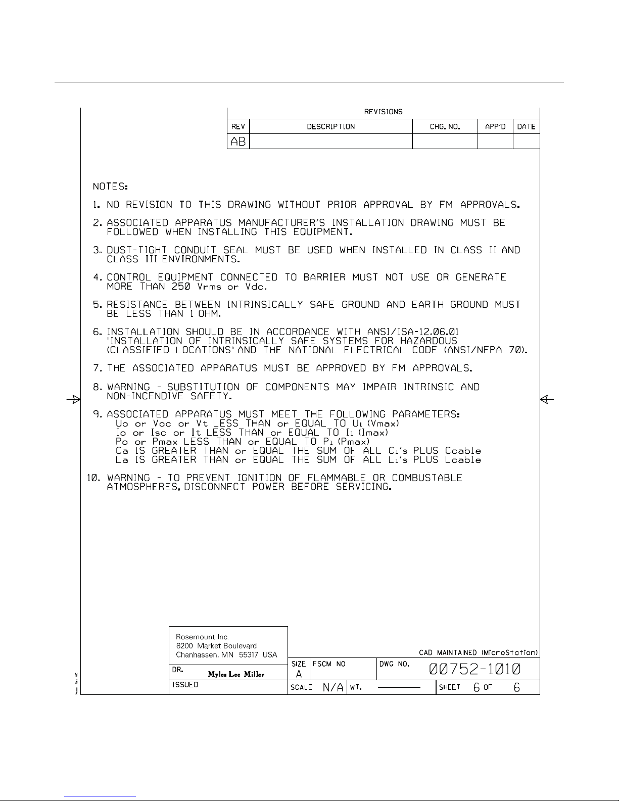
when connected in accordance with Rosemount drawing 00752-1010;
Temperature Code T4;
Non-incendive for Class I, Division 2, Groups A, B, C, and D.
Enclosure Type 4X
For entity parameters see control drawing 00752-1010.
www.rosemount.com
Page 40
Rosemount 752
Reference Manual
00809-0100-4377, Rev BA
September 2010
Canadian Standards
Association (CSA)
E6 Explosion-Proof for Class I, Division 1, Groups B, C, D; Dust-ignition
proof for Class II, Groups E, F, G;
Dust-ignition proof for Class III
Temperature Code T5, (T
Suitable for Class I, Division 2, Groups A, B, C,D;
Temperatue Code T3C (T
Enclosure Type 4x
I6/IFIntrinsically Safe for Class I, Division 1, Groups A, B, C, D when installed
in accordance with Rosemount drawing 00752-1020.
Temperature Code T3C (T
Enclosure Type 4X
European Certifications I1/IAATEX Intrinsic Safety
Certificate No.: Baseefa03ATEX0239X II 1G
EEx ia IIC T4 (-20°C
1180
Table B-1. Input Parameters:
Fieldbus FISCO Group IIC
Ui = 30 V dc Ui = 17.5 V dc
Ii = 300 mA Ii = 380 mA
Pi = 1.3 W Pi = 5.32 W
Ci = 0 Ci = 0
Li = 0 Li = 0
= 80 °C)
a
= 40 °C),
a
= 40 °C).
a
Ta 60°C)
SPECIAL CONDITIONS FOR SAFE USE (X)
1. When fitted with the transient option, the apparatus is not capable of
withstanding the 500V test as defined in Clause 6.4.12 of
EN 50020:2002. This must be taken into account during installation.
2. The enclosure may be aluminium, protec te d ag ain st low-levels of
impact by a coating of epoxy polyester or polyurethane paint. The r isk
of high-levels of impact must be considered in any installation and
protected accordingly.
E1 ATEX Flame-proof
Certificate No.: KEMA 03 ATEX2476X II 2 G
Ex d IIC T6 (-50 °C T
65°C)
a
Ex d IIC T5 (-20 °C Ta 80°C)
= 42.4V
V
max
1180
SPECIAL CONDITIONS FOR SAFE USE (X)
The Ex d blanking elements, cable glands and wirings shall be suitable for a
temperature of 90 °C. In case of repair, contact the manufacturer for
information on the dimensions of the flame proof joints.
B-2
Page 41

Reference Manual
00809-0100-4377, Rev BA
September 2010
Rosemount 752
N1 ATEX Non-incendive
Certificate No.: Baseefa03ATEX0240X II 3 G
EEx nA II T5 (Ta = -20 °C
Input Parameters:
= 45 V dc
U
i
= 0
C
i
= 0
L
i
SPECIAL CONDITIONS FOR SAFE USE (X)
The apparatus is not capable of with standing the 500V insulation test req uired
by Clause 9.1 of EN 50021: 1999. This must be taken into account when
installing the apparatus.
ND ATEX Dust
Certificate No.: KEMA 03 ATEX2476X II 1 D
Ex tD A20 IP66 T105 °C (-20 °C T
V = 42.4V Max
SPECIAL CONDITIONS FOR SAFE USE (X)
The Ex d blanking elements, cable glands and wirings shall be suitable for a
temperature of 90 °C. In case of repair, contact the manufacturer for
information on the dimensions of the flame proof joints.
Ta 70 °C)
85 °C)
a
Brazilian NCC (INMETRO)
E2 Inmetro Flameproof
Certificate No.: NCC 5500/09 BR-Ex d IIC
T6/T5 IP65 T6 (-20 °C T
T5 (-20 °C T
60 °C)
a
65 °C)
a
I2 Inmetro Intrinsic Safety
Certificate No.: NCC 5500/09 BR-Ex ia IIC
T4 (-20 °C T
60 °C)
a
SPECIAL CONDITION FOR SAFE USE:
1. For model 752... I2 fitted with the transient option, the apparatus is
not capable of withstanding the 500 V test as defined in clause 6.3.12
of IEC 60079-11:2006. This must be taken into account during
installation.
2. The enclosure maybe aluminum, protected against low-levels of
impact by a coating of epoxy polyester or polyurethane paint. The r isk
of high-levels of impact must be considered in any installation and
protected accordingly.
B-3
Page 42

Rosemount 752
IECEX CERTIFICATIONS N7 IECEx Non-incendive / Type N
Certificate No.: IECEx BAS 04.0030X
Ex nA II T5 (-40 °C T
SPECIAL CONDITION FOR SAFE USE (X):
When fitted with the transient option, the apparatus is not capable of
withstanding the 500 V electrical strength test as defined in Clause 8 of IEC
60079-15:1987. this must be taken into account when installing the
apparatus.
I7/IG IECEx Intrinsic Safety
Certificate No.: IECEx BAS 04.0028X
Ex ia IIC T4 (-20 °C T
Table B-2. Input Parameters
Fieldbus FISCO
Ui = 30 V Ui = 17.5 V
Ii = 300 mA Ii = 380 mA
Pi = 1.3 W Pi = 5.32 W
Ci = 0 Ci = 0
Li = 0 Li = 0
70 °C)
a
60 °C)
a
Reference Manual
00809-0100-4377, Rev BA
September 2010
SPECIAL CONDITION FOR SAFE USE (X):
1. When fitted with the transient option, the apparatus is not capable of
withstanding the 500 V electrical strength test as defined in clause
6.4.12 of IEC 60079-11:1999. This must be taken into account durin g
installation.
2. The enclosure maybe aluminum, protected against low-levels of
impact by a coating of epoxy polyester or polyurethane paint. The r isk
of high-levels of impact must be considered in any installation and
protected accordingly.
E7 IECEx Flame-proof
Certificate No.: IECEx KEM10.0066X
Ex d IIC T5 (-20 °C T
Ex d IIC T6 (-20 °C T
80 °C) Gb
a
65 °C) Gb
a
SPECIAL CONDITIONS FOR SAFE USE (X)
The Ex d blanking elements, cable glands and wirings shall be suitable for a
temperature of 90 °C. In case of repair, contact the manufacturer for
information on the dimensions of the flame proof joints.
B-4
Page 43
Reference Manual
00809-0100-4377, Rev BA
September 2010
APPROVAL DRAWINGS
Rosemount 752
B-5
Page 44
Rosemount 752
Reference Manual
00809-0100-4377, Rev BA
September 2010
B-6
Page 45
Reference Manual
00809-0100-4377, Rev BA
September 2010
Rosemount 752
B-7
Page 46
Rosemount 752
Reference Manual
00809-0100-4377, Rev BA
September 2010
B-8
Page 47
Reference Manual
00809-0100-4377, Rev BA
September 2010
Rosemount 752
B-9
Page 48
Rosemount 752
Reference Manual
00809-0100-4377, Rev BA
September 2010
B-10
Page 49
Reference Manual
00809-0100-4377, Rev BA
September 2010
Rosemount 752
Appendix C Block Information
Resource Block . . . . . . . . . . . . . . . . . . . . . . . . . . . . . . . . . . page C-1
LCD Transducer Block . . . . . . . . . . . . . . . . . . . . . . . . . . . . page C-7
RESOURCE BLOCK This section contains information on the Rosemount 752 Resource Block.
Descriptions of all Resource Block Parameters, errors, and diagnostics are
included. Also the modes, alarm detection, status handling, and
troubleshooting are discussed.
Definition
The resource block defines the physical resources of the device. The
resource block also handles functionality that is common across multiple
blocks. The block has no linkable inputs or outputs.
Parameters and
Descriptions
Parameter Index Valid Range Initial Value Units Other Description
ST_REV 1 0-255 The revision level of the static data associated with the
TAG_DESC 2 spaces N/A The user description of the intended application of the block.
STRATEGY 3 0 N/A The strategy field can be used to identify grouping of blocks.
ALERT_KEY 4 1-255 0 N/A The identification number of the plant unit.
MODE_BLK 5 O/S N/A The actual, target, permitted, and normal modes of the block.
BLOCK_ERR 6 E Read
RS_STATE 7 E Read
TEST_RW 8 N/A Read/write test parameter - used only for conformance
DD_RESOURCE 9 NULL N/A Read
MANUFAC_ID 10 Enumeration,
controlled by
FF
DEV_TYPE 11 0x7052 E Read
DEV_REV 12 0x03 N/A Read
DD_REV 13 1 N/A Read
The table below lists all of the configurable parameters of the Resource Block,
including the descriptions and index numbers for each.
function block.
Only
Only
Only
0x1151 N/A Read
Only
Only
Only
Only
This parameter reflects the error status associated with the
hardware or software components associated with a block. it
is a bit string, so that multiple errors may be shown.
State of the function block application state machine.
testing.
String identifying the tag of the resource which contains the
Device Description for the resource.
Manufacturer identification number - used by an interface
device to locate the DD file for the resource.
Manufacturer's model number associated with the resource used by interface devices to locate the DD file for the
resource.
Manufacturer revision number associated with the resource used by an interface device to locate the DD file for the
resource.
Revision of the DD associated with the resource - used by the
interface device to locate the DD file for the resource.
www.rosemount.com
Page 50

Reference Manual
00809-0100-4377, Rev BA
Rosemount 752
Parameter Index Valid Range Initial Value Units Other Description
GRANT_DENY 14 N/A Options for controlling access of host computer and local
control panels to operating, tuning and alarm parameters of
the block.
HARD_TYPES 15 0x0000 N/A Read
Only
RESTART 16 1: Run
2: Restart
resource
3: Restart with
defaults
4: Restart
processor
FEATURES 17 0x0C1b N/A Read
FEATURE_SEL 18 0 N/A Used to select resource block options.
CYCLE_TYPE 19 0x0003 N/A Read
CYCLE_SEL 20 0 N/A Used to select the block execution method for this resource.
MIN_CYCLE_T 21 1760
MEMORY_SIZE 22 set by mfgr Kbytes Read
NV_CYCLE_T 23 19200000
FREE_SPACE 24 0-100% % Read
FREE_TIME 25 0-100% % Read
SHED_RCAS 26 640000 1/32
SHED_ROUT 27 640000 1/32
FAULT_STATE 28 1: Clear
2: Active
SET_FSTATE 29 1: Off
2: Set
CLR_FSTATE 30 1: Off
2: Clear
MAX_NOTIFY 31 7 N/A Read
LIM_NOTIFY 32 0 to
MAX_NOTIFY
1 E Allows a manual restart to be initiated.
Only
Only
1/32
(55 msec)
(10 min.)
1 E Allows the Fault State condition to be manually initiated by
1 E Writing a Clear to this parameter will clear the device fault
MAX_NOTIFY N/A Maximum number of unconfirmed alert notify messages
millisec
1/32
millisec
millisec
millisec
E Read
Read
Only
Only
Read
Only
Only
Only
Only
Only
The types of hardware available as channel numbers. See
<Ref 15>
Used to show supported resource block options. See <Ref
15>and Table 25 for more information about supported
features. The supported features are:
SOFT_WRITE_LOCK_SUPPORT,
HARD_WRITE_LOCK_SUPPORT, R EPORTS, UNICODE,
MULTI_BIT_ALARM, FB_ACTION_RESTART_RELINK.
Identifies the block execution methods available for this
resource. See <Ref15> The supported cycle types are:
SCHEDULED, and
COMPLETION_OF_BLOCK_EXECUTION
Time duration of the shortest cycle interval of which the
resource is capable.
Available configuration memory in the empty resource. To be
checked before attempting a download.
Minimum time interval specified by the manufacturer for
writing copies of NV parameters to non-volatile memory. Zero
means it will never be automatically copied. At the end of
NV_CYCLE_T, only those parameters that have changed
need to be updated in NVRAM.
Percent of memory available for further configuration. Zero in
preconfigured resource.
Percent of the block processing time that is free to process
additional blocks.
Time duration at which to give up on computer writes to
function block RCas locations. Shed from RCas will never
happen when SHED_RCAS = 0.
Time duration at which to give up on computer writes to
function block ROut locations. Shed from ROut will never
happen when SHED_ROUT = 0
Condition set by loss of communication to an output block,
fault promoted to an output block or a physical contact. When
Fault State condition is set, then output function blocks will
perform their FSTATE actions. This parameter kept in the
device for compatibility because it does not contain any output
blocks.
selecting Set.
state if the field condition, if any, has cleared.
Maximum number of unconfirmed notify messages possible.
allowed.
September 2010
C-2
Page 51

Reference Manual
00809-0100-4377, Rev BA
September 2010
Parameter Index Valid Range Initial Value Units Other Description
CONFIRM_
TIME
WRITE_LOCK 34 1: Unlocked
UPDATE_EVT
. Unacknowledge
. Update State
. Time Stamp
. Static Revision
. Relative Index
33 640000 1/32
millisec
1 E If set, no writes from anywhere are allowed, except to clear
2: Locked
35 N/A R/W
RO
RO
RO
RO
The time the resource will wait for confirmation of receipt of a
report before trying again. Retry will not happen when
CONFIRM_TIME=0.
WRITE_LOCK. Block inputs will continue to be updated.
This alert is generated by any change to the static data.
Only “Unacknowledged” subindex is writeable (R/W). The rest
are Read Only (RO)
Rosemount 752
BLOCK_ALM 36 N/A R/W
RO
RO
RO
RO
ALARM_SUM 37 0 N/A The current alert status, unacknowledged states, unreported
ACK_OPTION 38 0: Auto Ack
Disabled
1: Auto Ack
Enabled
WRITE_PRI 39 0 - 15 0 N/A Priority of the alarm generated by clearing the write lock.
WRITE_ALM
. Unacknowledge
. Alram State
. Time Stamp
. Subcode
. Value
ITK_VER 41 set by FF 5 N/A Read
DISTRIBUTOR 42 "Rosemount" 0X26 E Read
DEV_STRING 43 0 to
XD_OPTION 44 Not supported E Read
FB_OPTION 45 Not supported E Read
DIAG_OPTION 46 Not supported E Read
MISC_OPTION 47 Not supported E Read
RB_SFTWR_
REV_MAJOR
RB_SFTWR_
REV_MINOR
RB_SFTWR_
REV_BUILD
40 N/A R/W
0xFFFFFFFF
48 3 N/A Read
49 set by build N/A Read
50 set by build N/A Read
0 N/A Selection of whether alarms associated with the block will be
RO
RO
RO
RO
Only
Only
0 N/A This is used to load new licensing into the device. The value
Only
Only
Only
Only
Only
Only
Only
The BLOCK_ALM is used for all configuration, hardware,
connection failure or system problems in the block. The cause
of the alert is entered in the subcode field. The first alert to
become active will set the Active status in the S tatus attribute.
As soon as the Unreported status is cleared by the alert
reporting task, another block alert may be reported without
clearing the Active status, if the subcode has changed.
states, and disabled states of the alarms associated with the
function block.
automatically acknowledged.
This alert is generated if the write lock parameter is cleared.
Only “Unacknowledged” subindex is writeable (R/W). The rest
are Read Only (RO)
Major revision number of the interoperability test case used in
certifying this device as interoperable. The format and range
are controlled by the Fieldbus Foundation.
Reserved for use as distributor ID. No Foundation
enumerations defined at this time.
can be written but will always read back with a value of 0.
Indicates which transducer block licensing options are
enabled. There will be no licensing of transducer options.
Indicates which function block licensing options are enabled.
This device does not support any function block licensing
options.
Indicates which diagnostics licensing options are enabled.
There will be no licensing of diagnostics options.
Indicates which miscellaneous licensing options are enabled.
This device does not support any miscellaneous licensing
options.
Major revision of software that the resource block was created
with.
Minor revision of software that the resource block was created
with.
Build of software that the resource block was created with.
C-3
Page 52

Rosemount 752
Parameter Index Valid Range Initial Value Units Other Description
RB_SFTWR_
REV_ALL
HARDWARE_
REV
OUTPUT_
BOARD_SN
FINAL_ASSY_
NUM
DETAILED_
STATUS
SUMMARY_
STATUS
MESSAGE_
DATE
MESSAGE_
TEXT
SELF_TEST 59 0:
DEFINE_WRITE_
LOCK
SAVE_CONFIG_NOW61 0:
SAVE_CONFIG_B
LOCKS
START_WITH_
DEFAULTS
SIMULATE_IO 64 0:
51 set by build N/A Read
Only
52 set by mfgr mfg block
53 set by mfgr N/A Read
54 set by mfgr N/A Read
55 See Table 22 E Read
56 0:Uninitialized
1: No repair
needed.
2: Repairable
3: Call service
center
57 0 N/A Date associated with the MESSAGE_TEXT parameter
58 spaces N/A Used to indicate changes made by the user to the device’s
Uninitialized
1: No test
2: Self test
60 0:
Uninitialized
1: Everything
Locked
2: Only
physical
device locked
Uninitialized
1: No save
2: Burn
EEPROM with
latest values
62 0 N/A Read
63 0-4 1 E 0 = Uninitialized
Uninitialized
1: Off
2: On
0 E Read
1 E Used to self test the device. Tests are device specific.
1 E Allows the operator to select how WRITE_LOCK behaves.
1 E Allows the user to optionally save all non-volatile information
0 E Read
2
N/A Read
Only
Only
Only
Only
Only
Only
Only
The string will contains the following fields:
Major rev: 1-3 characters, decimal number 0-255
Minor rev: 1-3 characters, decimal number 0-255
Build rev: 1-5 characters, decimal number 0-255
Time of build: 8 characters, xx:xx:xx, military time
Day of week of build: 3 characters, Sun, Mon, …
Month of build: 3 characters, Jan, Feb..
Day of month of build: 1-2 characters, decimal number 1-31
Year of build: 4 characters, decimal
Builder: 7 characters, login name of builder
Hardware revision of that hardware that has the resource
block in it. Returns the hardware revision value stored in the
manufacturing block.
Output board serial number.
The same final assembly number placed on the neck label.
Indicates the state of the transmitter.
An enumerated value of repair analysis.
installation, configuration, or calibration.
The initial value is “lock everything”. If the value is set to “lock
only physical device” then the resource and transducer blocks
of the device will be locked but changes to function blocks will
be allowed.
immediately.
Number of EEPROM blocks that have been modified since
last burn. This value will count down to zero when the
configuration is saved.
1 = do not power-up with NV defaults
2 = power-up with default node address
3 = power-up with default pd_tag and node address
4 = power-up with default data for the entire communications
stack (no application data)
Status of Simulate jumper/switch
Reference Manual
00809-0100-4377, Rev BA
September 2010
C-4
Page 53

Reference Manual
00809-0100-4377, Rev BA
September 2010
Parameter Index Valid Range Initial Value Units Other Description
SECURITY_IO 65 0:
Uninitialized
1: Off
2: On
SIMULATE_
STATE
DOWNLOAD_
MODE
RECOMMENDED
_ACTION
FAILED_PRI 69 0 - 15 0 N/A Designates the alarming priority of the FAILED_ALM.
FAILED_ENABLE 70 0 E Read
FAILED_MASK 71 See Table 25 0 E Mask of FAILED_ALM. Corresponds bit of bit to
FAILED_ACTIVE 72 0 E Read
FAILED_ALM
. Unacknowledged
. Alarm State
. Time Stamp
. Subcode
. Value
MAINT_PRI 74 0 - 15 0 N/A Designates the alarming priority of the MAINT_ALM
MAINT_ENABLE 75 0 E Read
MAINT_MASK 76 See Table 26 0 E Mask of MAINT_ALM. Corresponds bit of bit to
MAINT_ACTIVE 77 0 E Read
MAINT_ALM
. Unacknowledged
. Alarm State
. Time Stamp
. Subcode
. Value
ADVISE_PRI 79 0 - 15 0 N/A Designates the alarming priority of the ADVISE_ALM
ADVISE_
ENABLE
66 0 - 3 1 E Read
67 0 - 2 1 E Gives access to the boot block code for over the wire
68 0 E Read
73 N/A
78 N/A
80 0 Read
0 E Read
Only
Only
Only
Only
Only
R/W
RO
RO
RO
RO
Only
Only
R/W
RO
RO
RO
RO
Only
Status of Security jumper/switch
The state of the simulate jumper
0 = Uninitialized
1 = Jumper/switch off, simulation not allowed
2 = Jumper/switch on, simulation not allowed (need to cycle
jumper/switch)
3 = Jumper/switch on, simulation allowed
downloads
0 = Uninitialized
1 = Run Mode
2 = Download Mode
Enumerated list of recommended actions displayed with a
device alert.
Enabled FAILED_ALM alarm conditions. Corresponds bit for
bit to the FAILED_ACTIVE. A bit on means that the
corresponding alarm condition is enabled and will be
detected. A bit off means the corresponding alarm condition is
disabled and will not be detected.
FAILED_ACTIVE. A bit on means that the condition is
masked out from alarming.
Enumerated list of failure conditions within a device.
Alarm indicating a failure within a device which makes the
device non-operational.
Only “Unacknowledged” subindex is writeable (R/W). The rest
are Read Only (RO)
Enabled MAINT_ALM alarm conditions. Corresponds bit for
bit to the MAINT_ACTIVE. A bit on means that the
corresponding alarm condition is enabled and will be
detected. A bit off means the corresponding alarm condition is
disabled and will not be detected.
MAINT_ACTIVE. A bit on means that the condition is masked
out from alarming.
Enumerated list of maintenance conditions within a device.
Alarm indicating the device needs maintenance soon. If the
condition is ignored, the device will eventually fail.
Enabled ADVISE_ALM alarm conditions. Corresponds bit for
bit to the ADVISE_ACTIVE. A bit on means that the
corresponding alarm condition is enabled and will be
detected. A bit off means the corresponding alarm condition is
disabled and will not be detected.
Rosemount 752
C-5
Page 54

Reference Manual
00809-0100-4377, Rev BA
Rosemount 752
Parameter Index Valid Range Initial Value Units Other Description
ADVISE_MASK 81 See Table 27 0 E Mask of ADVISE_ALM. Corresponds bit of bit to
ADVISE_ACTIVE. A bit on means that the condition is
masked out from alarming.
ADVISE_ACTIVE 82 0 E Read
Only
ADVISE_ALM
. Unacknowledged
. Alarm State
. Time Stamp
. Subcode
. Value
HEALTH_INDEX 84 1-100 100 None Read
PWA_SIMULATE 85 Off/On (0-1) Off None Note
(1) PWA simulate may only be turned on if the physical hardware simulate switch/jumper is Active.
83 N/A
R/W
RO
RO
RO
RO
Only
Enumerated list of advisory conditions within a device.
Alarm indicating advisory alarms. These conditions do not
have a direct impact on the process or device integrity.
Only “Unacknowledged” subindex is writeable (R/W). The rest
are Read Only (RO)
This is an indication of the overall condition of the device. This
value is Used in conjunction with PlantWeb Alerts.
(1)
Parameter that allows direct writes to PWA active parameters
and the detailed status bytes that activate the Plant Web
alerts. The simulate switch/jumper must be “ON” before
PWA_SIMULATE can be turned on.
0 = Simulation off
1 = Simulation on
September 2010
C-6
Page 55

Reference Manual
00809-0100-4377, Rev BA
September 2010
Rosemount 752
LCD TRANSDUCER
BLOCK
Parameter Index Description
ALERT_KEY 4 The identification number of the plant unit.
BLK_TAG_1 15 The tag of the block containing DP1.
BLK_TAG_2 21 The tag of the block containing DP2.
BLK_TAG_3 27 The tag of the block containing DP3.
BLK_TAG_4 33 The tag of the block containing DP4.
BLK_TAG_5 39 The tag of the block containing DP5.
BLK_TAG_6 45 The tag of the block containing DP6.
BLK_TAG_7 51 The tag of the block containing DP7.
BLK_TAG_8 57 The tag of the block containing DP8.
BLK_TYPE_1 14 The enumerated block type for DP1's block.
BLK_TYPE_2 20 The enumerated block type for DP2's block.
BLK_TYPE_3 26 The enumerated block type for DP3's block.
BLK_TYPE_4 32 The enumerated block type for DP4's block.
BLK_TYPE_5 38 The enumerated block type for DP5's block.
BLK_TYPE_6 44 The enumerated block type for DP3's block.
BLK_TYPE_7 50 The enumerated block type for DP7's block.
BLK_TYPE_8 56 The enumerated block type for DP8's block.
BLOCK_ALM 8 The BLOCK_ALM is used for all configuration, hardware, connection failure or system problems
in the block. The cause of the alert is entered in the subcode field. The first alert to become active
will set the Active status in the Status attribute. As soon as the Unreported status is cleared by the
alert reporting task, another block alert may be reported without clearing the Active status, if the
subcode has changed.
BLOCK_ERR 6 This parameter reflects the error status associated with the hardware or software components
associated with a block. it is a bit string, so that multiple errors may be shown.
COLLECTION_DIRECTORY 12 A directory that specifies the number, starting indicies, and DD Item ID's of the data collections in
CUSTOM_TAG_1 17 The block description that is displayed for DP1.
CUSTOM_TAG _2 23 The block description that is displayed for DP2.
CUSTOM_TAG _3 29 The block description that is displayed for DP3.
CUSTOM_TAG _4 35 The block description that is displayed for DP4.
CUSTOM_TAG_5 41 The block description that is displayed for DP5.
CUSTOM_TAG_6 47 The block description that is displayed for DP6.
CUSTOM_TAG_7 53 The block description that is displayed for DP7.
CUSTOM_TAG_8 59 The block description that is displayed for DP8.
CUSTOM_UNITS_1 19 This is the user entered units that are displayed when UNITS_TYPE_1=Custom.
CUSTOM_UNITS _2 25 This is the user entered units that are displayed when UNITS_TYPE_2=Custom.
CUSTOM_UNITS _3 31 This is the user entered units that are displayed when UNITS_TYPE_3=Custom.
CUSTOM_UNITS _4 37 This is the user entered units that are displayed when UNITS_TYPE_4=Custom.
CUSTOM_UNITS_5 43 This is the user entered units that are displayed when UNITS_TYPE_5=Custom.
CUSTOM_UNITS_6 49 This is the user entered units that are displayed when UNITS_TYPE_6=Custom.
CUSTOM_UNITS_7 55 This is the user entered units that are displayed when UNITS_TYPE_7=Custom.
CUSTOM_UNITS_8 61 This is the user entered units that are displayed when UNITS_TYPE_8=Custom.
DISPLAY_PARAM_SEL 13 This will determine which Display Parameters are active.
MODE_BLK 5 The actual, target, permitted, and normal modes of the block.
PARAM_INDEX_1 16 The relative index of DP1 within its block.
each transducer block.
Bit 0 = DP1
Bit 1 = DP2
Bit 2 = DP3
Bit 3 = DP4
Bit 4 = DP5
Bit 5 = DP6
Bit 6 = DP7
Bit 8 = DP8
C-7
Page 56

Reference Manual
00809-0100-4377, Rev BA
Rosemount 752
Parameter Index Description
PARAM_INDEX_2 22 The relative index of DP2 within its block.
PARAM_INDEX_3 28 The relative index of DP3 within its block.
PARAM_INDEX_4 34 The relative index of DP4 within its block.
PARAM_INDEX_5 40 The relative index of DP5 within its block.
PARAM_INDEX_6 46 The relative index of DP6 within its block.
PARAM_INDEX_7 52 The relative index of DP7 within its block.
PARAM_INDEX_8 58 The relative index of DP8 within its block.
ST_REV 1 The revision level of the static data associated with the function block.
STRATEGY 3 The strategy field can be used to identify grouping of blocks.
TAG_DESC 2 The user description of the intended application of the block.
TRANSDUCER_DIRCTORY 9 A directory that specifies the number and starting indicies of the transducers in the transducer
block.
TRANSDUCER_TYPE 10 Identifies the transducer that follows.
UNITS_TYPE_1 18 This parameter determines where the units for the display parameter come from.
UNITS_TYPE_2 24 This parameter determines where the units for the display parameter come from.
UNITS_TYPE_3 30 This parameter determines where the units for the display parameter come from.
UNITS_TYPE_4 36 This parameter determines where the units for the display parameter come from.
UNITS_TYPE_5 42 This parameter determines where the units for the display parameter come from.
UNITS_TYPE_6 48 This parameter determines where the units for the display parameter come from.
UNITS_TYPE_7 54 This parameter determines where the units for the display parameter come from.
UNITS_TYPE_8 60 This parameter determines where the units for the display parameter come from.
UPDATE_EVT 7 This alert is generated by any change to the staic data.
XD_ERROR 11 Provides additional error codes related to transducer blocks.
September 2010
C-8
Page 57

Reference Manual
00809-0100-4377, Rev BA
September 2010
Rosemount 752
Index
A
Address . . . . . . . . . . . . . . . . . . 1-2
Temporary Node . . . . . . . . . 1-2
ADVISE_ACTIVE . . . . . . . . . . . 2-12
ADVISE_ALM . . . . . . . . . . . . . 2-13
ADVISE_ENABLED . . . . . . . . . 2-12
ADVISE_MASK . . . . . . . . . . . . 2-12
ADVISE_PRI . . . . . . . . . . . . . . 2-12
Advisory Alarms . . . . . . . . . . . . 2-12
ADVISE_ACTIVE . . . . . . . 2-12
ADVISE_ALM . . . . . . . . . . 2-13
ADVISE_MASK . . . . . . . . . 2-12
ADVISE_PRI . . . . . . . . . . . 2-12
Alarms
ADVISE_ACTIVE . . . . . . . 2-12
ADVISE_ALM . . . . . . . . . . 2-13
ADVISE_MASK Parameter
ADVISE_MASK . . . . . 2-12
ADVISE_PRI . . . . . . . . . . . 2-12
Advisory . . . . . . . . . . . . . . 2-12
FAILED_ACTIVE . . . . . . . . 2-11
FAILED_ALARMS . . . . . . . 2-11
FAILED_ALM . . . . . . . . . . 2-11
FAILED_ENABLED . . . . . . 2-11
FAILED_MASK . . . . . . . . . 2-11
FAILED_PRI . . . . . . . . . . . 2-11
MAINT_ACTIVE . . . . . . . . 2-12
MAINT_ALARMS . . . . . . . 2-11
MAINT_ALM . . . . . . . . . . . 2-12
MAINT_ENABLED . . . . . . . 2-12
MAINT_MASK . . . . . . . . . . 2-12
MAINT_PRI . . . . . . . . . . . 2-12
PlantWeb . . . . . . . . .2-11, 2-13
Arithmetic Block . . . . . . . . . . . . . 1-3
B
BLK_TAG_# . . . . . . . . . . . . . . 2-14
BLK_TYPE_# . . . . . . . . . . . . . 2-14
BLOCK_ERR
Resource Block . . . . . . . . . . 4-5
C
Capabilities . . . . . . . . . . . . . . . . 2-9
Block Execution Times . . . . . 2-9
Host Timer . . . . . . . . . . . . . 2-9
VCRs . . . . . . . . . . . . . . . . . 2-9
Certifications
Electro magnetic compatibility
Changing Modes . . . . . . . . . . . . 2-7
Configuration . . . . . . . . . . . . . . 2-1
Custom Meter . . . . . . . . . . 2-14
LCD Transducer Block . . . . 2-13
Resource Block . . . . . . . . . 2-9
Considerations
Electrical, fieldbus
Custom meter configuration . . . 2-14
CUSTOM_TAG_# . . . . . . . . . . 2-14
CUSTOM_UNITS_# . . . . . . . . 2-14
. . . . . . . . 2-3
B-1
D
Device Description . . . . . . . . . . 1-2
Diagrams
Fieldbus terminal block
DISPLAY_PARAM_SEL . . . . . . 2-14
. . . . 2-3
E
Electro magnetic compatibility . . . B-1
EMC . . . . . . . . . . . . . . . . . . . . B-1
Execution Times . . . . . . . . . . . . 2-9
F
FAILED_ACTIVE alarms . . . . . 2-11
FAILED_ALARMS . . . . . . . . . . 2-11
FAILED_ACTIVE . . . . . . . 2-11
FAILED_ALM . . . . . . . . . . 2-11
FAILED_ENABLED . . . . . . 2-11
FAILED_MASK . . . . . . . . . 2-11
FAILED_PRI . . . . . . . . . . . 2-11
FAILED_ALM . . . . . . . . . . . . . 2-11
FAILED_ENABLED alarms . . . . 2-11
FAILED_MASK alarms . . . . . . . 2-11
FAILED_PRI alarms . . . . . . . . 2-11
FEATURES
FEATURES_SEL
Features . . . . . . . . . . . . . . . . . . 2-9
FEATURES, FEATURES_SEL . . 2-9
Features . . . . . . . . . . . . . . 2-9
Reports . . . . . . . . . . . . . . . 2-9
Soft W Lock, Hard W Lock . 2-10
Unicode . . . . . . . . . . . . . . . 2-9
Foundation fieldbus function blocks . .
. . . . . . . 2-10
1-3
FREE_SPACE . . . . . . . . . . . . . .2-8
G
General Block Information
Block Instantiation
Capabilities . . . . . . . . . . . . .2-7
Link Active Scheduler . . . . . .2-7
Modes . . . . . . . . . . . . . . . . .2-7
Grounding . . . . . . . . . . . . . . . . .2-6
External assembly . . . . . . . .2-6
Fieldbus protocol . . . . . . . . .2-3
Internal connection . . . . . . . .2-6
Shielded wire . . . . . . . . . . . .2-4
. . . . . . . .2-7
H
Hazardous locations . . . . . . . . . .2-6
I
Input Selector (ISEL) block . . . . .1-3
Input Selector Block . . . . . . . . . .1-3
Installation
Power supply
Fieldbus protocol
Power up . . . . . . . . . . . . . . .2-3
Wiring
Fieldbus
Instantiation, Block . . . . . . . . . . .2-8
Integrator Block . . . . . . . . . . . . .1-3
Introduction . . . . . . . . . . . . . . . .1-1
. . . . . . . . . . . .2-3
. . . . . .2-3
L
LCD meter . . . . . . . . . . . . . . . .2-13
LCD Transducer Block 1-3, 2-13, C-7
Messaging . . . . . . . . . . . . .2-13
Parameters . . . . . . . . . . . . C-7
LCD Transducer block . . . . . . . . .4-6
Block Error . . . . . . . . . . . . .4-6
Self Test . . . . . . . . . . . . . . .4-6
Lightning . . . . . . . . . . . . . . . . . .2-4
LIM_NOTIFY . . . . . . . . . . . . . .2-10
Link Active Scheduler . . . . . . . . .2-8
www.rosemount.com
Page 58

Rosemount 752
Reference Manual
00809-0100-4377, Rev BA
September 2010
M
MAINT_ACTIVE . . . . . . . . . . . . 2-12
MAINT_ALARMS . . . . . . . . . . . 2-11
MAINT_ACTIVE . . . . . . . . 2-12
MAINT_ALM . . . . . . . . . . . 2-12
MAINT_ENABLED . . . . . . . 2-12
MAINT_MASK . . . . . . . . . . 2-12
MAINT_PRI . . . . . . . . . . . 2-12
MAINT_ALM . . . . . . . . . . . . . . 2-12
MAINT_ENABLED . . . . . . . . . . 2-12
MAINT_MASK . . . . . . . . . . . . . 2-12
MAINT_PRI . . . . . . . . . . . . . . . 2-12
Manual Operation . . . . . . . . . . . 3-1
Master Reset Method . . . . . . . . . 3-2
MAX_NOTIFY . . . . . . . . . . . . . 2-10
LIM_NOTIFY . . . . . . . . . . . 2-10
Methods . . . . . . . . . . . . . . . . . . 3-1
MODE_BLK.TARGET . . . . . . . . . 2-7
MODE_BLOCK.ACTUAL . . . . . . 2-7
Modes
Changing Modes . . . . . . . . . 2-7
Permitted Modes . . . . . . . . . 2-7
Types of Modes . . . . . . . . . . 2-7
Auto . . . . . . . . . . . . . . 2-7
Man . . . . . . . . . . . . . . . 2-7
Other . . . . . . . . . . . . . . 2-7
Out of Service . . . . . . . . 2-7
N
Network Parameters . . . . . . . . . . 2-9
Node address . . . . . . . . . . . . . . 1-2
O
Operation . . . . . . . . . . . . . . . . . 2-1
Operation and Maintenance
Resource Block
. . . . . . . . . . 3-2
P
PARAM_INDEX_# . . . . . . . . . . 2-14
Parameter
ADVISE_ACTIVE
ADVISE_ALM . . . . . . . . . . 2-13
ADVISE_ENABLED . . . . . . 2-12
ADVISE_PRI . . . . . . . . . . . 2-12
BLK_TAG_# . . . . . . . . . . . 2-14
BLK_TYPE_# . . . . . . . . . . 2-14
BLOCK_ERR . . . . . . . . . . . 4-5
CUSTOM_TAG_# . . . . . . . 2-14
CUSTOM_UNITS_# . . . . . . 2-14
DEFINE_WRITE_LOCK . . . 2-10
DISPLAY_PARAM_SEL . . . 2-14
FAILED_ACTIVE . . . . . . . . 2-11
FAILED_ALARMS . . . . . . . 2-11
FAILED_ALM . . . . . . . . . . 2-11
FAILED_ENABLED . . . . . . 2-11
FAILED_MASK . . . . . . . . . 2-11
. . . . . . . 2-12
FAILED_PRI . . . . . . . . . . . 2-11
FEATURES . . . . . . . . . . . . 2-9
FEATURES_SEL . . . . . . . 2-10
FREE_SPACE . . . . . . . . . . 2-8
LCD Transducer Block . . . . . C-7
LIM_NOTIFY . . . . . . . . . . 2-10
MAINT_ACTIVE . . . . . . . . 2-12
MAINT_ALARMS . . . . . . . 2-11
MAINT_ALM . . . . . . . . . . 2-12
MAINT_ENABLED . . . . . . 2-12
MAINT_MASK . . . . . . . . . 2-12
MAINT_PRI . . . . . . . . . . . 2-12
MAX_NOTIFY . . . . . . . . . 2-10
MODE_BLK.TARGET . . . . . 2-7
MODE_BLOCK_ACTUAL . . 2-7
Network . . . . . . . . . . . . . . . 2-9
PARAM_INDEX_# . . . . . . 2-14
RECOMMENDED_ACTION 2-13
REPORTS . . . . . . . . . . . . . 2-9
Resource Block . . . . . . . . . C-1
UNICODE . . . . . . . . . . . . . 2-9
UNITS_TYPE_# . . . . . . . . 2-14
WRITE_LOCK . . . . . . . . . 2-10
Permitted Modes . . . . . . . . . . . . 2-7
PID Block . . . . . . . . . . . . . . . . . 1-3
PID block . . . . . . . . . . . . . . . . . 1-3
PlantWeb Alarms . . . . . . .2-11, 2-13
Advisory . . . . . . . . . . . . . . 2-12
FAILED_ALARMS . . . . . . . 2-11
MAINT_ALARMS . . . . . . . 2-11
Power Conditioner
Fieldbus protocol . . . . . . . . 2-3
Power supply
Fieldbus protocol . . . . . . . . 2-3
Power up . . . . . . . . . . . . . . . . . 2-3
Power supply fieldbus protocol . .
2-3
Proportional/Integral/Derivative (PID)
function block
. . . . . . . . . . . . . . 1-3
R
Recommended Actions . . . . . . 2-13
PlantWeb Alarms . . . . . . . 2-13
RECOMMENDED_ACTION . . . 2-13
Reports . . . . . . . . . . . . . . . . . . 2-9
Resource Block . . 1-3, 2-9, 3-2, 4-5,
C-1
Block Errors . . . . . . . . . . . . 4-5
Block Information . . . . . . . . C-1
Configuration . . . . . . . . . . . 2-9
Detailed Status . . . . . . . . . . 4-5
FEATURES, FEATURES_SEL . .
2-9
Operation and Maintenance . 3-2
Parameters . . . . . . . . . . . . C-1
BLOCK_ERR . . . . . . . . 4-5
Summary Status . . . . . . . . . 4-5
Resource block . . . . . . . . . . . . . C-1
S
Security . . . . . . . . . . . . . . . . . .2-10
Security (Write Protect) . . . . . . . .2-2
Self Test . . . . . . . . . . . . . . . . . .4-6
Service Support . . . . . . . . . . . . .1-2
Signal Characterizer Block . . . . . .1-3
Soft W Lock, Hard W Lock . . . . .2-10
Surges . . . . . . . . . . . . . . . . . . . .2-4
Switches and jumpers
Security (Write Protect) . . . . .2-2
T
Tagging
Fieldbus protocol
Termina l block diagrams
Fieldbus protocol . . . . . . . . .2-3
Timer Recommendations, Host . .2-9
Transient
Protection . . . . . . . . . . . . . .2-4
Transients . . . . . . . . . . . . . . . . .2-4
Transmitter functions . . . . . . . . . .3-1
Troubleshooting . . . . . . . . . . . . .4-2
Flowchart . . . . . . . . . . . . . .4-2
LCD Transducer block . . . . .4-6
Reference table . . . . . . . . . .4-2
Resource Block . . . . . . . . . .4-5
Types of Modes
Auto . . . . . . . . . . . . . . . . . .2-7
Man . . . . . . . . . . . . . . . . . .2-7
Other Types of Modes . . . . . .2-7
Out of Service . . . . . . . . . . .2-7
. . . . . . . . .2-5
U
Unicode . . . . . . . . . . . . . . . . . . .2-9
UNITS_TYPE_# . . . . . . . . . . . .2-14
V
Virtual Communication Relationship
. . . . . . . . . . . . . . . . . . .2-9
(VCRs)
Network Parameters . . . . . . .2-9
W
Wiring
Connect fieldbus
Fieldbus diagram . . . . . . . . .2-4
Surges . . . . . . . . . . . . . . . .2-4
Transients . . . . . . . . . . . . . .2-4
. . . . . . . . .2-3
Index-2
Page 59

Page 60

Reference Manual
00809-0100-4377, Rev BA
September 2010
Rosemount 752
Standard Terms and Conditions of Sale can be found at www.rosemount.com/terms_of_sale
The Emerson logo is a trademark and service mark of Emerson Electric Co.
Rosemount. and the Rosemount logotype are registered trademarks of Rosemount Inc.
PlantWeb is a mark of one of the Emerson Process Management companies.
Foundation fieldbus is a registered trademark of the Fieldbus Foundation.
All other marks are the property of their respective owners.
© 2010 Rosemount Inc. All rights reserved.
Emerson Process Management
Rosemount Inc.
8200 Market Boulevard
Chanhassen, MN 55317 USA
T (U.S.) 1-800-999-9307
T (International) (952) 906-8888
F (952) 949-7001
www.rosemount.com
00809-0100-4377 Rev BA, 9/10
Emerson Process Management
GmbH & Co.
Shipping Address:
Argelsrieder Feld 3
82234 Wessling
Germany
Tel 49 (8153) 9390
Fax 49 (8153) 939172
Emerson Process Management Pte Ltd.
1 Pandan Crescent
Singapore 128461
Tel (665) 777-8211
Fax (665) 777-0947
 Loading...