

Page 1
00813-0100-4378, Rev FA
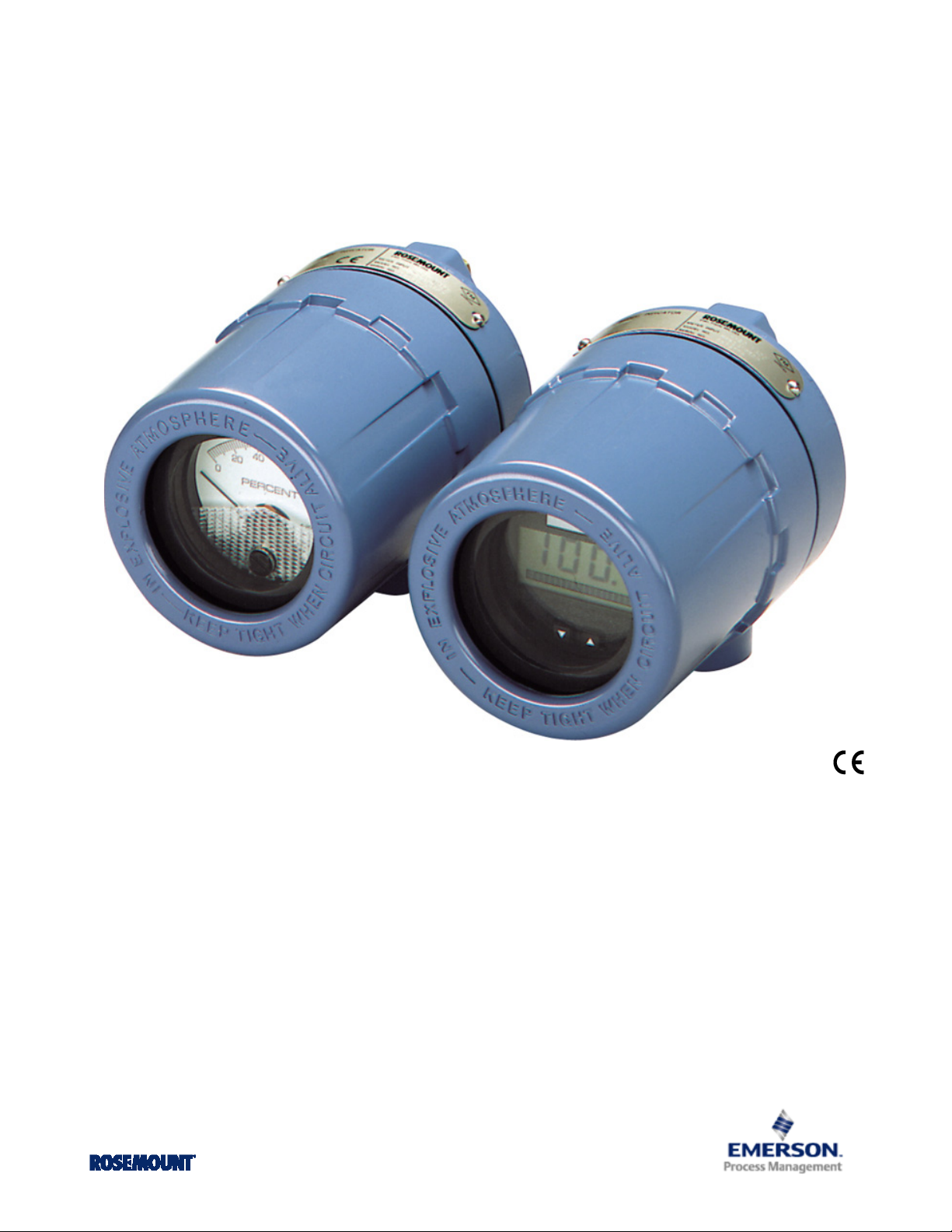
Rosemount 751 Field Signal Indicator
Product Data Sheet
August 2014
Available with an LCD display or analog meter
Compact, rugged, and designed for industrial environments
Available with explosion-proof and intrinsic safety certifications
Provides flexible mounting options
Page 2

Rosemount 751
Transcend Your Integral Meter Display with the Rosemount 751
August 2014
The Rosemount 751 Field Signal Indicators provide a means of
displaying important process variables. These devices operate
with any two-wire transmitter that measures input variables
such as pressure, flow, liquid level, or temperature. Rosemount
indicators are ideal for installations where an integral meter
would be difficult to view.
Rosemount 751 Indicators are designed for use in industrial
environments where all-weather performance is necessary.
These units are vibration- and corrosion-resistant, and
explosion-proof or intrinsically safe. An LCD display meter or
analog meter may be ordered to meet specific application
requirements.
LCD display meter
The LCD display meter may be configured from a 4 mA point of
–999 to a 20 mA point of 9999 with a linear or square-root
response. A 20-segment bar graph at the bottom of the display
directly represents the 4–20 mA signal.
Changing the 4 mA and 20 mA points is easy. Just remove the
housing and meter covers, and press the meter faceplate
buttons. The meter can be rotated in 90-degree increments
within the enclosure for convenient viewing.
1
The large, 2
a 2-in. long scale for easy readability. A zero adjustment is
located on the meter faceplate (accessible with the housing
cover removed).
The meter can be rotated within the enclosure
for convenient viewing in 90-degree increments.
/4-in. diameter meter face has
Analog meter
With the analog meter, several meter scaling options are
available to suit special application requirements with ±2
percent of calibrated span accuracy. Linear 0 to 100 percent
meter scaling is adequate for the majority of measurement
applications. With a flow transmitter, a logarithmic 0 to 100
percent flow scale is available. As an option, the user can specify
special meter scaling for direct readout in psi, gph, °F, °C, or
other convenient engineering units.
Content
Ordering Information . . . . . . . . . . . . . . . . . . . . . . . . . . . . . . . 3
Specifications . . . . . . . . . . . . . . . . . . . . . . . . . . . . . . . . . . . . . . 5
Product Certifications . . . . . . . . . . . . . . . . . . . . . . . . . . . . . . . 7
Dimensional Drawings . . . . . . . . . . . . . . . . . . . . . . . . . . . . . . 10
2
www.rosemount.com
Page 3
August 2014
Rosemount 751
Ordering Information
Specification and selection of product materials, options, or components must be made by the purchaser of the equipment. See
page 5 for more information on Material Selection.
Table 1. 751 Field Signal Indicator Ordering Information
★ The Standard offering represents the most common models and options. These options should be selected for best delivery.
__The Expanded offering is subject to additional delivery lead time.
Model Product description
751 Remote Signal Indicator
Input signal
A 4–20 mA dc ★
B 10–50 mA dc (not available with LCD display meter) ★
C 40–200 mV dc (not available with LCD display meter) ★
Meter scale
M1 Linear Analog Meter, 0–100% Scale ★
M2 Square Root Analog Meter, 0–100% Flow ★
M6 Square Root Analog Meter, 0–10 √ ★
(1)
M4
(1)
M7
(1)
M8
(1)
M9
Product certificates
NA No Approval Required ★
E2 INMETRO Flameproof ★
I2 INMETRO Intrinsic Safety ★
K2 INMETRO Flameproof, Intrinsic Safety ★
E3 NEPSI Flameproof ★
E5 FM Explosion-Proof ★
E6 CSA Explosion-Proof ★
E7 IECEx Flameproof ★
E8 ATE X Flameproof ★
I5 FM Intrinsic Safety and Non-incendive ★
I6 CSA Intrinsic Safety ★
I7 IECEx Intrinsic Safety ★
I8 ATEX Intrinsic Safety ★
N1 ATEX Type N Non-incendive ★
C6 CSA Intrinsic Safety, Non-incendive, and Explosion-proof approval combination ★
K5 FM Intrinsic Safety, Non-incendive, and Explosion-proof approval combination ★
KM Technical Regulations Customs Union (EAC) Flameproof, Intrinsic Safety ★
IM Technical Regulations Customs Union (EAC) Intrinsic Safety ★
EM Technical Regulations Customs Union (EAC) Flameproof ★
NM Technical Regulations Customs Union (EAC) Type N ★
Linear LCD display Meter, 0–100% Scale ★
Special Scale LCD display Meter (specify range, mode, and engineering units) ★
Square Root LCD display Meter, 0–100% Flow ★
Square Root LCD display Meter, 0–10 √ ★
www.rosemount.com
3
Page 4
Rosemount 751
August 2014
Table 1. 751 Field Signal Indicator Ordering Information
★ The Standard offering represents the most common models and options. These options should be selected for best delivery.
__The Expanded offering is subject to additional delivery lead time.
Options (include with selected model number)
Mounting bracket
B Mounting Bracket for Flat Surface or 2-in. Pipe ★
Reducer
C Stainless Steel Reducer ¾- to ½-in. for Conduit Connection (see Figure 1 for reference) ★
Bar code tag
BT Customer Specified Barcode Tag ★
Extended Product warranty
WR3 3-year limited warranty ★
WR5 5-year limited warranty ★
Typical model number: 751 A M1 NA BC
(1) May be reconfigured in the field.
4
www.rosemount.com
Page 5

August 2014
Specifications
Rosemount 751
Housing specifications
Physical specifications
Material selection
Emerson provides a variety of Rosemount product with various
product options and configurations including materials of
construction that can be expected to perform well in a wide
range of applications. The Rosemount product information
presented is intended as a guide for the purchaser to make an
appropriate selection for the application. It is the purchaser’s
sole responsibility to make a careful analysis of all process
parameters (such as all chemical components, temperature,
pressure, flow rate, abrasives, contaminants, etc.), when
specifying product, materials, options and components for the
particular application. Emerson Process Management is not in a
position to evaluate or guarantee the compatibility of the
process fluid or other process parameters with the product,
options, configuration or materials of construction selected.
Conformance to specifications [±3σ (Sigma)]
Technology leadership, advanced manufacturing techniques,
and statistical process control ensure specification conformance
to at least ±3
Materials of construction
Enclosure
Low-copper aluminum
Paint
Polyurethane
O-rings
Buna N
Meter mounting materials
GE polyphenylene oxide plastic
Electrical connections
3-pole terminal block with 8–32 nickel-plated brass screw
terminals, with
reducer available as an option).
Enclosure rating
NE MA Typ e 4x. C SA Typ e 4x. I P66
Weight
Indicator only: 1.8 kg (4 lb)
Indicator with optional mounting bracket: 2.27 (5 lb)
σ.
3
/4–14 NPT conduit (stainless steel 3/4- to
1
/2-in.
LCD display meter specifications
Functional specifications
Input signal
4–20 mA dc
Display
4 mA point limits
–999 to 1000
Span limits
200 to 9999
The sum of the 4 mA point and span must not exceed 9999.
Adjustments are made using non-interactive zero and span
buttons.
Display options
Standard display response is linear with mA input. Optional
square root or filtered response may be selected.
Overload limitations
666 mA, maximum
Temperature limits
Storage
–40 to 85 °C (–40 to 185 °F)
Operating
–40 to 70 °C (–40 to 185 °F)
(1) For temperatures below -20 °C or above 60 °C the LCD display may not be
readable, but the loop will remain intact and the LCD display will not be
damaged.
Humidity limitation
0 to 95 percent non-condensing relative humidity
Update period
750 ms
Response time
Responds to changes in input within a maximum of two update
periods. If the filter is activated, then the display responds to the
change within nine update periods.
Voltage drop
0.7 Vdc typical, 1.0 Vdc maximum
(1)
Tagging
The indicator will be tagged, at no charge, in accordance with
customer requirements. All tags are stainless steel. The standard
tag is permanently attached to the indicator. Tag character
height is
request.
www.rosemount.com
1
/16 in. (1.6 mm). A wired-on tag is available upon
5
Page 6

Rosemount 751
August 2014
Performance specifications
Digital display resolution
0.05 percent of calibrated range ± 1 digit
Analog bar graph resolution
5.0 percent of calibrated range
Indication accuracy
0.25 percent of calibrated range ± 1 digit
Stability
0.1 percent calibrated range ± 1 digit per six months
Temperature effect
0.01 percent of calibrated range per °C on zero
0.02 percent of calibrated range per °C on span over the
operating temperature range
Power interrupt
All calibration constants are stored in EEPROM memory and are
not affected by power loss.
Failure mode
LCD display meter failure will not affect transmitter operation.
Under/Over range indication
Input current < 3.5 mA: Display blank
Input current > 22.0 mA: Display flashes 112.5 percent of full
scale value or 9999, whichever is less
Physical specification
Meter size
21/4-in. diameter face with four
1
/2-in. high characters
Analog meter specifications
Functional specifications
Input signal
• 4–20 mA dc
• 10–50 mA dc
• 40–200 mV
Note
Maximum series resistance is ten ohms for ammeters.
Meter indication
0 to 100 percent linear scale
0 to 100 percent flow scale
Special optional ranges
Overload limitation
150 percent of rated end scale value for two minutes
Temperature limits
-40 to 65 °C (–40 to 150 °F)
Humidity limits
0 to 100 percent relative humidity
Zero adjustment
Adjustment screw on face of meter
Performance specifications
Indication accuracy
±2 percent of calibrated span
Temperature effect
Less than 2 percent of full scale at any point within the
temperature limits
Physical specification
Meter size
21/4-in. diameter face with 2-in. long scale
6
www.rosemount.com
Page 7

August 2014
Product Certifications
Rosemount 751
Approved manufacturing locations
Rosemount Inc. — Chanhassen, Minnesota USA
Emerson Process Management GmbH & Co. — Wessling,
Germany
Emerson Process Management Asia Pacific Private Limited —
Singapore
Emerson Process Management India PVT LTD - Daman, India
European directive information
The EC declaration of conformity can be found on
00825-0100-4378. The most recent revision can be found at
www.rosemount.com.
Ordinary location certification for FM approvals
As standard, the transmitter has been examined and tested to
determine that the design meets basic electrical, mechanical,
and fire protection requirements by FM Approvals, a nationally
recognized testing laboratory (NRTL) as accredited by the
Federal Occupational Safety and Health Administration (OSHA).
Electro Magnetic Compatibility (EMC)
EN 61326:2006
ATE X Direc tive (94 /9/ EC)
Emerson Process Management complies with the ATEX
Directive.
Hazardous locations certifications
North American certifications
Entity Parameters:
V
= 40 V
max
I
= 165 mA
max
I
= 225 mA
max
Ci = 0
L
= 0
i
Special Condition for Safe Use (X):
1. When connected per Rosemount drawing 01151-0214
(I.S.).
K5 Combination of E5 and I5
NEMA Enclosure Type 4X
Canadian Standards Association (CSA) approvals
Certificate Number: 1718395
E6 Explosion-Proof for Class I, Division 1, Groups C and D;
Standards: C22.2 No. 25-1966, C22.2 No. 30-M1986,
C22.2 No. 94-M1991, C22.2 No. 142-M1987
Class I, Division 2, Groups A, B, C, and D;
Class II, Division 1, Groups E, F, and G; Dust-Ignition Proof
for Class III, Division 1, Groups A, B, C, and D.
CSA Enclosure type 4X
I6 Intrinsically safe
Standards: C22.2 No. 157-1992, C22.2 No. 213-M1987,
Class I, Division 1, Groups A, B, C, and D
CSA enclosure type 4X
Special Condition for Safe Use (X):
1. When connected per Rosemount drawing 00751-0068
with approved barrier system (I.S.).
C6 CSA: Explosion-proof; Intrinsically Safe
Combination of E6 and I6
Factory Mutual (FM) approvals
E5 Certificate Number: 0T2H8.AE
Standards: FM3600-1989, FM3615-1989
Explosion-Proof for Class I, Division 1, Groups B, C, and D.
Dust-Ignition Proof for Class II, Division 1, Groups E, F, and
G. Dust-ignition Proof Class III, Division 1
Indoor and outdoor use, NEMA Type 4X
I5 Certificate Number: 0T9H2.AX
Standards: FM3600-1989, FM3610-1988, FM3611-1986,
FM3810-1989
Intrinsically safe for Class I, Division 1, Groups A, B, C, and
D; Class II, Division 1, Groups E, F, and G; Class III, Division
1. Nonincendive for Class I, Division 2, Groups A, B, C, and
D.
www.rosemount.com
International certifications
E7 IECEx Flameproof
Certification IECEx DEK 11.0082X
Standards: IEC 60079-0:2007, IEC 60079-1:2007
Ex d IIC T5/T6 Gb
T5 (-20 °C ≤ T
T6 (-20 °C ≤ T
IP66
V
= 60V
max
Special Condition for Safe Use (X):
1. Transmitters have an NPT cable entry thread; A certified
flameproof thread adapter or cable gland must be used to
maintain type of protection. Contact manufacturer for
flame path dimensions. Cable glands and wiring must be
suitable for greater than 80 °C.
I7 IECEx Intrinsic Safety
Certification IECEx BAS 11.0064X
amb
amb
≤ 70 °C)
≤ 40 °C)
7
Page 8

Rosemount 751
August 2014
Standards: IEC 60079-0:2007-10, IEC 60079-11:2006
Ex ia IIC T5/T6 Ga
T5 (-60 °C ≤ T
T6 (-60° C ≤ T
amb
amb
≤ 80 °C)
≤ 40 °C)
IP66
Entity Parameters:
Ui = 60 V
Ii = 200 mA
L
= 0
i
Ci = 0
Special Condition for Safe Use (X):
1. The enclosure is made of aluminum and finished with a
protective paint finish; care should be taken to protect it
from impact or abrasion when installed in a zone 0
environment.
European certifications
E8 ATEX Flameproof
Certificate Number: DEKRA11ATEX0240X
Standards: EN60079-0:2008, EN60079-1:2009,
Ex II 2 G Ex d IICT5/T6 Gb
T5 (-60 °C to 80 °C)|
T6 (-60 °C ≤ T
IP66
= 60 V
V
max
Special Condition for Safe Use (X):
1. Transmitters have an NPT cable entry thread; A certified
flameproof thread adapter or cable gland must be used to
maintain type of protection. Contact manufacturer for
flame path dimensions. Cable glands and wiring must be
suitable for greater than 80 °C.
I8 ATE X Int rins ic Safet y
Certificate Number: Baseefa03ATEX0448X
Standards:EN60079-0:2009, EN60079-11:2007
Ex II 1 G Ex ia IIC T5/T6
T5 (-60 °C ≤ T
T6 (-60 °C ≤ T
IP66
Input Parameters:
Ui = 60 V
I
= 200 mA
i
Li = 0
= 0
C
i
amb
amb
amb
≤ 40 °C)
≤ 80 °C);
≤ 40 °C)
Special Condition for Safe Use (X):
1. The enclosure is made of aluminum and finished with a
protective paint finish; care should be taken to protect it
from impact or abrasion when installed in a zone 0
environment.
N1 ATEX Type N
Certificate Number: Baseefa03ATEX0454
Standards: EN60079-0:2009, EN60079-15:2010
Ex II 3G Ex nA II T6 Gc
T6 (-40 ºC ≤ T
amb
≤ 70 ºC)
IP66
Rated Voltage = 5 V
Technical Regulations Customs Union (EAC)
EM, IM, EM, NM Contact an Emerson Process Management
representative for additional information
Brazilian approvals
E2 Brazil INMETRO Flameproof
Certificate number: NCC 5486.09X
Standards: ABNT NBR IEC 60079-0:2008, ABNT NBR IEC
60079-1:2009
Ex d IIC T6 Gb
IP65
Input parameters:
= 12-45 Vcc
U
n
U
= 60 Vcc
max
In= 4-20 mA
I
- 666 mA
max
Special Condition for Safe Use (X):
1. Transmitters have an NPT cable entry thread; A certified
flameproof thread adapter or cable gland must be used to
maintain type of protection.
I2 Brazil INMETRO Intrinsic Safety
Certificate number: NCC 7013.10X
Standards: ABNT NBR IEC 60079-0:2008, ABNT NBR IEC
60079-11:2009, ABNT NBR IEC 60079-26:2008
Ex ia IIC T5/T6 Ga
T5 (-60 °C≤T
T6 (-60 °C≤T
Input Parameters:
= 60 V
U
i
= 200 mA
I
i
P
= 2.4 W
i
L
= 0
i
= 0
C
i
amb
amb
≤80 °C);
≤40 °C)
8
www.rosemount.com
Page 9

August 2014
Rosemount 751
Special Condition for Safe Use (X):
1. The enclosure is made of aluminum and finished with a
protective paint finish; care should be taken to protect it
from impact or abrasion when installed in a zone 0
environment.
K2 INMETRO: Flameproof; Intrinsic Safety
Combination of E2 and I2
Chinese approvals
E3 China (NEPSI) Flameproof
Certificate Number: GY071011
Standards: GB3836.1-2000, GB3836.2-2000
Ex ia IIC T5/T6 (except acetylene)
Ex ia IIC T5/T6
T6 (-20 °C ≤ T
amb
≤ 60 °C)
Special Condition for Safe Use (X):
1. Transmitters have an NPT cable entry thread; A certified
flameproof thread adapter or cable gland must be used to
maintain type of protection. Contact manufacturer for
flame path dimensions. The earth connection should be
connected reliably.
I3 China (NEPSI) Intrinsic Safety
Certificate number: GY091234X
Standards: GB3836.1-2000, GB3836.4-2000
Ex ia IIC T5/T6
T5 (-60 °C ≤ T
T6 (-60 °C ≤ T
≤ 80 °C);
amb
≤ 70 °C)
amb
Input Parameters:
= 60 V
U
i
I
= 200 mA
i
Ci = 0
Li = 0
Special Condition for Safe Use (X):
1. The transmitter must be installed to minimize the risk of
impact or friction with other metal surfaces.
www.rosemount.com
9
Page 10

Rosemount 751
A
B
C
D
E
F
G
H
J
K
L
M
N
O
I
Dimensional Drawings
Figure 1. Rosemount 751 Field Signal Indicator
August 2014
A. Terminal Screws
B. Housing O-Ring
C. Field Wiring Terminals
D. Loop Protection Diode
E. Mounting Boss (tapped)
F. Mounting Bracket (optional)
G. Mounting Bolt with Washer
H. U-Bolt for 2-In. Pipe
10
I. Cover Clamp
J. Housing
K. Optional 3/4- to 1/2-In. Conduit Reducing Bushing (if required)
L. Meter
M. Cover Bushing
N. Cover Foam Spacer
O. Housing Cover
www.rosemount.com
Page 11

August 2014
A
A
B
C
D
E
F
3.75
(95)
7.0
(178)
1.0
(25)
6.0
(152)
3.0
(76)
2.8
(71)
1.1
(28)
4.2
(107)
4.0
(102)
5.0
(127)
4.1
(104)
Figure 2. Rosemount 751 Dimensional Drawing
Dimensions are in inches (millimeters).
A. Optional Mounting Bracket
B. Permanent Tag
C. 0.37 (9.4) Diameter Holes (typically four places)
Rosemount 751
D. FM or CSA Tag (if required)
E. 3/4-14 NPT Conduit Connection
F. 2 -i n. Pipe
www.rosemount.com
11
Page 12

Rosemount 751
00813-0100-4378 Rev FA
Product Data Sheet
August 2014
Emerson Process Management
Rosemount Inc.
8200 Market Boulevard
Chanhassen, MN 55317 USA
T (U.S.) 1-800-999-9307
T (International) (952) 906-8888
F (952) 906-8889
www.rosemount.com
Emerson Process Management
Asia Pacific Pte Ltd
1 Pandan Crescent
Signapore 128461
T +65 6777 8211
F +65 6777 0947
Service Support Hotline: +65 6770 8711
Email: Enquiries@AP.EmersonProcess.com
www.rosemount.com
Standard Terms and Conditions of Sale can be found at www.rosemount.com\terms_of_sale
The Emerson logo is a trade mark and service mark of Emerson Electric Co.
Rosemount and the Rosemount logotype are registered trademarks of Rosemount Inc.
All other marks are the property of their respective owners.
© 2014 Rosemount Inc. All rights reserved.
Emerson Process Management
Blegistrasse 23
P.O. Box 1046
CH 6341 Baar
Switzerland
T +41 (0) 41 768 6111
F +41 (0) 41 768 6300
www.rosemount.com
Emerson Process Management
Latin America
1300 Concord Terrace, Suite 400
Sunrise Florida 33323 USA
T + 1 954 846 5030
www.rosemount.com
00813-0100-4378, Rev FA, 08/14
 Loading...