

Page 1
Quick Start Guide
00825-0200-4708, Rev DA
Rosemount™ 708 Wireless Acoustic
Transmitter
June 2016
Page 2

Quick Start Guide
June 2016
NOTICE
This guide provides basic guidelines for the Rosemount 708. It does not provide instructions for detailed
configuration, diagnostics, maintenance, service, troubleshooting, or installations. Refer to the Rosemount
708 Reference Manual (document number 00809-0100-4708) for more instruction. This guide and the
manual are available electronically on www.rosemount.com.
Explosions could result in death or serious injury.
Installation of this transmitter in an explosive environment must be in accordance with the appropriate
local, national, and international standards, codes, and practices. Review the Product Certifications
section for any restrictions associated with a safe installation.
Before connecting a Field Communicator in an explosive atmosphere, ensure the instruments are
installed in accordance with intrinsically safe field wiring practices.
This device complies with Part 15 of the FCC Rules. Operation is subject to the following conditions:
This device may not cause harmful interference.
This devi ce must accept any interferen ce received, including interference that may cause undesired
operation.
This device must be installed to ensure a minimum antenna separation distance of 8-in. (20 cm) from all
persons.
The power module may be replaced in a hazardous area. The power module has surface resistivity greater
than one gigaohm and must be properly installed in the wireless device enclosure. Care must be taken
during transportation to and from the point of installation to prevent a potential electrostatic charging
hazard.
Polymer enclosure has surface resistivity greater than one gigaohm. Care must be taken during
transportation to and from the point of installation to prevent a potential electrostatic charging hazard.
NOTICE
Shipping considerations for wireless products
The unit was shipped without the power module installed. Remove the power module prior to shipping the
unit.
Each power module contains one “D” size primary lithium battery. Primary lithium batteries are regulated in
transportation by the U.S. Department of Transportation, and are also covered by IATA (International Air
Transport Association), ICAO (International Civil Aviation Organization), and ARD (European Ground
Transportation of Dangerous Goods). It is the responsibility of the shipper to ensure compliance with these
or any other lo cal requirem ents. Consult current regulations and requirements before shipping.
Contents
Overview . . . . . . . . . . . . . . . . . . . . . . . . . . . . . . . . 3
Wireless considerations . . . . . . . . . . . . . . . . . . . . 3
Physical installation . . . . . . . . . . . . . . . . . . . . . . . 4
2
Device network configuration . . . . . . . . . . . . . . 8
Verify operation. . . . . . . . . . . . . . . . . . . . . . . . . . . 9
Product certifications. . . . . . . . . . . . . . . . . . . . . 13
Page 3
June 2016
1.0 Overview
Figure 1. Rosemount 708 Wireless Acoustic Transmitter
D
Quick Start Guide
B
C
A
A. Power module cover — power module is inside device; unscrew cap for access
B. Waveguide — acoustic and temperature sensors
C. Electronics cover — cover is sealed and cannot be removed
D. Stainless steel mounting bands — used to connect the acoustic transmitter to the piping
E. Pipe — the acoustic transmitter is installed directly to the pipe
E
2.0 Wireless considerations
2.1 Power up sequence
The Emerson™ Smart Wireless Gateway should be installed and functioning
properly before any wireless devices are powered. Install the power module,
Smart Wireless 701PGNKF into the Rosemount 708 to power the device. This
results in a simpler and faster network installation. Enabling active advertising on
the Gateway ensures new devices are able to join the network faster. For more
information see the Smart Wireless Gateway Manual (document number
00809-0200-4420).
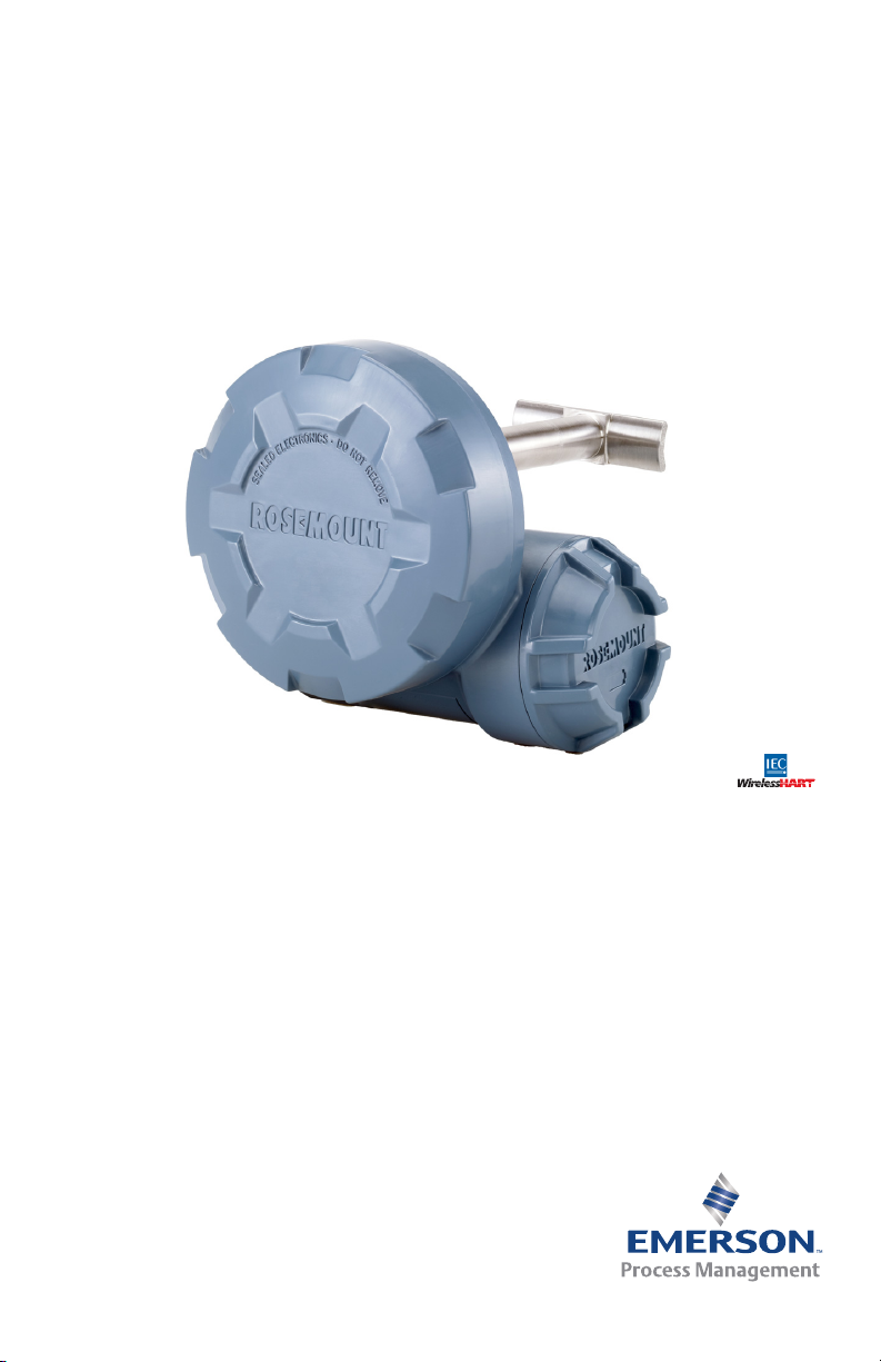
2.2 Antenna position
The antenna is internal to the acoustic transmitter. To achieve optimal range,
orient the transmitter with the waveguide horizontal and the power module
closest to the ground as shown in Figure 2. Good connectivity can also be
achieved in other orientations. The antenna should also be approximately 3 ft.
(1 m) from any large structure, building, or conductive surface to allow for clear
communication to other devices.
3
Page 4
Quick Start Guide
Figure 2. Antenna Position
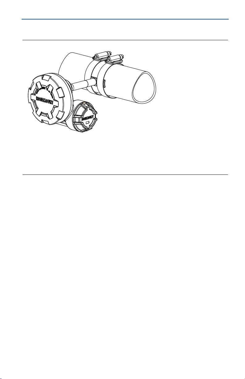
3.0 Field Communicator connections
The power module needs to be installed in the device for the Field Communicator
to interface with the Rosemount 708. This transmitter uses the green power
module; order model number 701PGNKF. Field communication with this device
requires a HART
Field Communicator connections are located on the power module. The power
module is keyed and can only be inserted in one orientation. Refer to Figure 3 for
instructions on connecting the Field Communicator to the Rosemount 708.
Figure 3. Connection Diagram
®
protocol-based Field Communicator using the correct 708 DD.
June 2016
4.0 Physical installation
The acoustic transmitter is connected directly to the piping being measured.
4.1 Mounting
For high temperature mounting, see page 5.
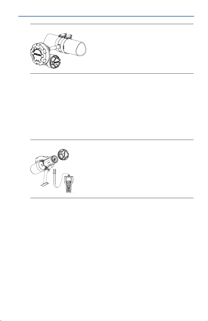
1. Locate the Rosemount 708 on a horizontal section of piping as close as
possible to the equipment to be monitored. Align the waveguide of the
transmitter as shown in Figure 4 and Figure 5.
2. The mounting location should be free of foreign matter and corrosion to
ensure good contact between the piping and the waveguide.
3. Tighten each clamp to 90 in-lb (10,2 N-m). Trim the excess clamp band
material to prevent unwanted acoustic noise.
4. If commissioning the device, install the green power module (see Figure 6).
4
Page 5
June 2016
Quick Start Guide
5. Ensure the power module cover is fully tightened to prevent moisture ingress.
The lip of the polymer power module cover should be in contact with the
surface of the polymer enclosure to ensure a proper seal. Do not over tighten.
Figure 4. Transmitter Alignment
Figure 5. Transmitter Alignment Top View
Figure 6. Power Module Installation
Note
Wireless devices should be powered up in order of proximity from the Smart Wireless
Gateway, beginning with the closest device to the Smart Wireless Gateway. This will result
in faster network formation.
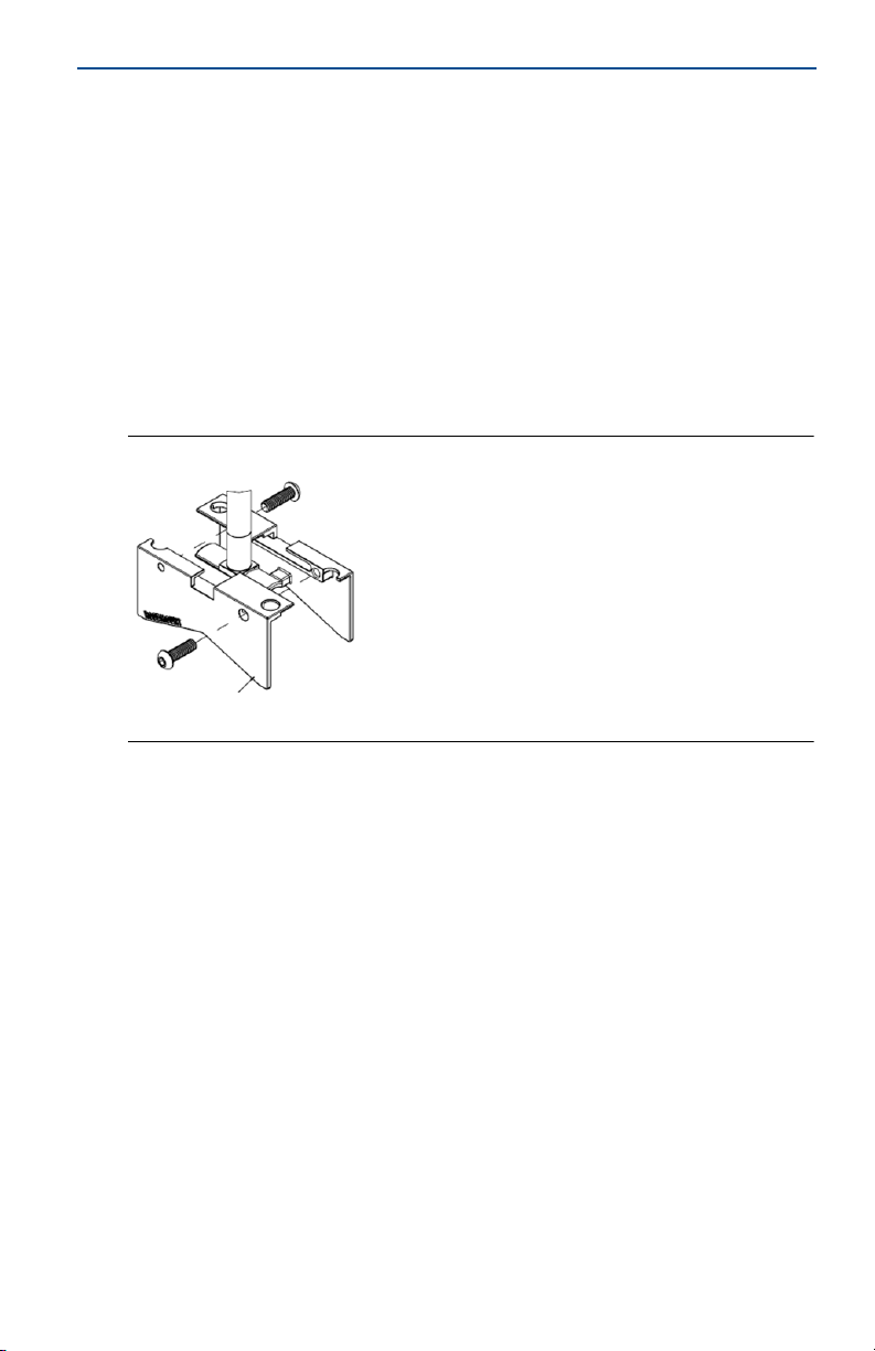
4.2 Mounting in a high temperature application
High temperature mounting hardware should be used when process
temperatures exceed 260 °C (500 °F).
1. Place the foot of the transmitter in between the standoff mounting hardware
plates as shown in Figure 7.
2. Press standoff plates together so plates and transmitter foot are aligned.
5
Page 6
Quick Start Guide
3. Tighten each screw to 90 in-lb (10,2 N-m).
4. Locate the Rosemount 708 and high temperature mounting hardware on a
horizontal section of the piping as close as possible to the equipment to be
monitored. The mounting location should be free of foreign matter and
corrosion to ensure good contact between the piping and the mounting
hardware.
5. Insert the U-bolt through the standoff mounting hardware.
6. Tighten each bolt to 90 in-lb (10,2 N-m) (see Figure 8).
7. If commissioning the device, install the green power module (see Figure 6).
8. Ensure the power module cover is fully tightened to prevent moisture ingress.
The lip of the polymer power module cover should be in contact with the
surface of the polymer enclosure to ensure a proper seal. Do not over tighten.
Figure 7. High Temperature Mounting Hardware
June 2016
6
Page 7

June 2016
(97)
Figure 8. Rosemount 708 Acoustic Transmitter with High Temperature
Standoff and Fastener Kit
6.86
(174)
1.81
(46)
Quick Start Guide
3.80
A. For pipe sizes 0.5 to 2.5-in.
Dimensions are in inches (millimeters).
A
4.3 Mounting considerations
1. Mounting bands should be inspected periodically and re-tightened if
necessary. Some loosening may occur after initial installation due to thermal
expansion/contraction.
2. The waveguide must be in direct contact with the pipe unless the high
temperature mounting hardware is being used.
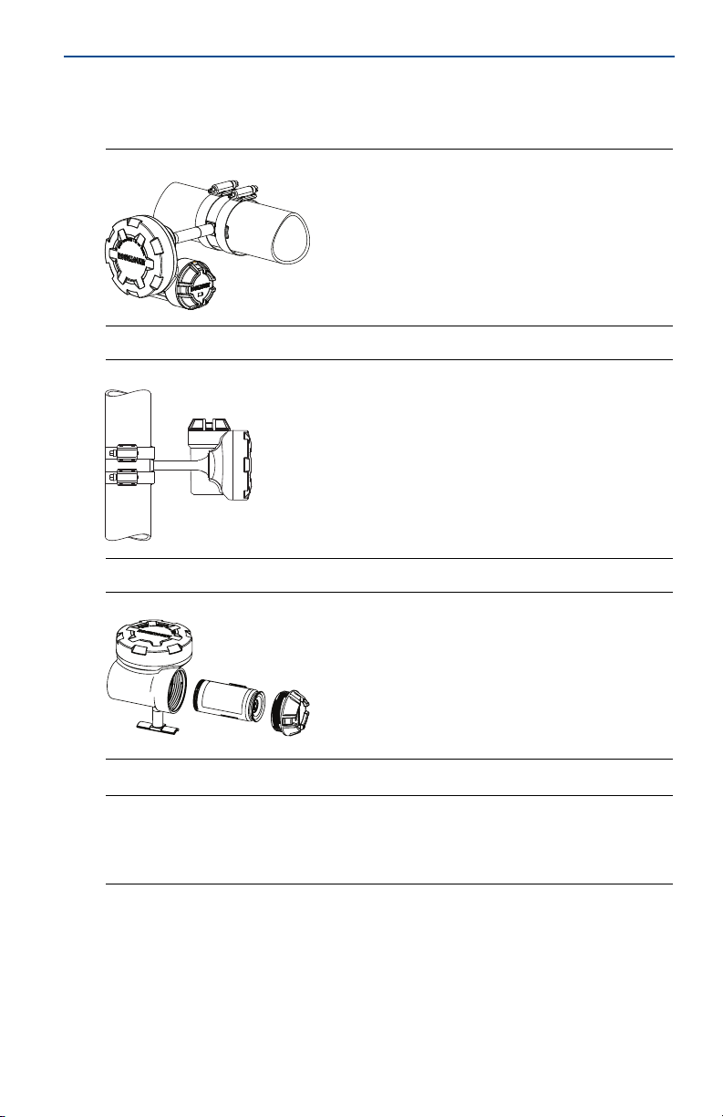
3. Insulate process piping to minimize ambient temperature effects (see Figure
9). Insulation thickness over the top of the waveguide foot should not exceed
1-in. (2,54 cm).
4. For best results, mount the transmitter within 6-in. (15,24 cm) of the
equipment to be monitored.
5. The stainless steel mounting bands could be affected by stress corrosion and
potentially fail when in the presence of chlorides.
6. The transmitter should be installed such that steam or other high temperature
fluids do not directly impinge the housing of the device.
7. If installing the device on a steam trap, the device should be installed on the
upstream side of the trap.
7
Page 8

Quick Start Guide
1-in.
Figure 9. Piping Insulation Side View
5.0 Device network configuration
In order to communicate with the Smart Wireless Gateway, and ultimately the
information system, the transmitter must be configured to communicate with
the wireless network. This step is the wireless equivalent of connecting wires
from a transmitter to the host system. Using a Field Communicator or AMS
Device Manager, enter the network ID and join key so they match the network ID
and join key of the Gateway and other devices in the network. If the network ID
and join key are not the same as the Gateway, the acoustic transmitter will not
communicate with the network. The network ID and join key may be obtained
from the Smart Wireless Gateway on the Setup>Network>Settings page on the
web server, shown in Figure 10.
June 2016
®
Figure 10. Gateway Network Settings
8
Page 9

June 2016
Quick Start Guide
5.1 AMS Device Manager
Right click on the acoustic transmitter and select Configure. When the menu
opens, select Join Device to Network and follow the method to enter the
network ID and join key.
5.2 Field Communicator
The network ID and join key may be changed in the wireless device by using the
following Fast Key sequence. Set both network ID and join key.
Table 1. Setting the Network ID and Join Key
Function Fast Key sequence Menu items
Join Device to Network 2, 1, 2 Network ID, Set Join Key
6.0 Verify operation
There are three ways to verify operation: using the Field Communicator, using the
Smart Wireless Gateway’s integrated web interface, or by using AMS Suite
Wireless Configurator or AMS Device Manager.
If the Rosemount 708 was configured with the network ID and join key, and
sufficient time has passed, the transmitter will be connected to the network. If
network ID and join key were not configured, reference “Troubleshooting” on
page 11.
Note
It may take several minutes for the device to join the network.
6.1 Field Communicator
For HART protocol Wireless transmitter communication, a Rosemount 708
Device Driver (DD) is required. To obtain the latest DD, visit the Emerson Process
Management Easy Upgrade site at:
http://www2.emersonprocess.com/en-US/documentation/deviceinstallkits. The
communication status may be verified in the wireless device using the following
Fast Key sequence.
Table 2. Communication Status Verification Fast Key Sequence
Func tion Fast Key sequence Menu items
Join Status, Wireless Mode, Join Mode, Number of
Communications 3, 4
Available Neighbors, Number of Advertisements Heard,
Number of Join Attempts
9
Page 10

Quick Start Guide
6.2 Smart Wireless Gateway
Using the Smart Wireless Gateway’s integrated web interface, navigate to the
Explorer page as shown in Figure 11. Locate the device in question and verify all
status indicators are good (green).
Figure 11. Smart Wireless Gateway Explorer Page
6.3 AMS Suite Wireless Configurator
When the device has joined the network, it will appear in the Device Manager as
illustrated in Figure 12. For HART protocol Wireless transmitter communication, a
708 DD is required. To obtain the latest DD, visit the Emerson Process
Management Easy Upgrade site at:
http://www2.emersonprocess.com/en-US/documentation/deviceinstallkits.
June 2016
Figure 12. Device Manager
10
Page 11

June 2016
Quick Start Guide
Note
SteamLogic™ software is provided for viewing steam trap status. Refer to the manual on the
CD for more information.
6.4 Troubleshooting
If the device is not joined to the network after power up, verify the correct
configuration of the network ID and join key, and that active advertising has been
enabled on the Smart Wireless Gateway. The network ID and join key in the
device must match the network ID and join key of the Gateway.
The network ID and join key may be obtained from the Gateway on the
Setup>Network>Settings page of the web server (see Figure 13 on page 11). The
network ID and join key may be changed in the wireless device by following the
Fast Key sequence shown below.
Table 3. Changing Network ID and Join Key Fast Key Sequence
Func tion Fast Key sequence Menu items
Join Device to Network 2, 1, 2 Network ID, Set Join Key
Figure 13. Smart Wireless Gateway Network Settings
11
Page 12

Quick Start Guide
6.5 Field Communicator use
Note
In order to communicate with a Field Communicator, power the Rosemount 708 by
connecting the power module. For more information on the power module, refer to the
Product Data Sheet (document number 00813-0100-4701).
Table 4 includes Fast Key sequences frequently used to interrogate and configure
the device. For additional information, refer to the Rosemount 708 Reference
Manual (document number 00809-0100-4708).
Table 4. Rosemount Fast Key Sequence
Function Fast Key sequence Menu items
Device Information 2, 2, 5
Guided Setup 2, 1
Manual Setup 2, 2
Wireless 2, 2, 1 Network ID, Join Device to Network, Broadcast Information
Figure 14. Field Communicator Connections
Tag, Long Tag, Descriptor, Message, Date, Country, SI Unit
Basic Setup, Join Device to Network, Configure Update
Wireless, Sensor, HART, Security, Device Information,
Control
Rates, Alert Setup
Power
June 2016
12
Page 13

June 2016
Quick Start Guide
7.0 Product certifications
Rev 1.0
7.1 European Directive Information
A copy of the EC Declaration of Conformity can be found at the end of the Quick
Start Guide. The most recent revision of the EC Declaration of Conformity can be
found at www.rosemount.com.
7.2 Telecommunication Compliance
All wireless devices require certification to ensure they adhere to regulations
regarding the use of the RF spectrum. Nearly every country requires this type of
product certification.
Emerson is working with governmental agencies around the world to supply fully
compliant products and remove the risk of violating country directives or laws
governing wireless device usage.
7.3 FCC and IC
This device complies with Part 15 of the FCC Rules. Operation is subject to the
following conditions: This device may not cause harmful interference. This device
must accept any interference received, including interference that may cause
undesired operation. This device must be installed to ensure a minimum antenna
separation distance of 20 cm from all persons.
7.4 Ordinary Location Certification from FM Approvals
As standard, the transmitter has been examined and tested to determine that the
design meets the basic electrical, mechanical, and fire protection requirements
by FM Approvals, a nationally recognized test laboratory (NRTL) as accredited by
the Federal Occupational Safety and Health Administration (OSHA).
7.5 Installing in North America
The US National Electrical Code® (NEC) and the Canadian Electrical Code (CEC)
permit the use of Division marked equipment in Zones and Zone marked
equipment in Divisions. The markings must be suitable for the area classification,
gas, and temperature class. This information is clearly defined in the respective
codes.
USA
I5 FM Intrinsically Safe (IS)
Certificate: 3043245
Standards: FM Class 3600 – 1998, FM Class 3610 – 2010, FM Class 3810 – 2005, NEMA
Markings: IS CL I, DIV 1, GP A, B, C, D T4; CL 1, Zone 0 AEx ia IIC T4;
250 – 2003, ANSI/IEC 60529 - 2004
T4(–40 °C ≤ T
00708-1000; Type 4X
≤ +70 °C) when installed per Rosemount drawing
a
13
Page 14

Quick Start Guide
Special Conditions for Safe Use (X):
1. The Rosemount 708 shall only be used with the 701PGNKF Rosemount
SmartPower™ Battery Pack.
2. Potential Electrostatic charging Hazard — See Instructions.
Canada
I6 CSA Intrinsically Safe
Certificate: 2439890
Standards: CAN/CSA C22.2 No. 0-M91, CAN/CSA C22.2 No. 94-M91, CSA Std C22.2 No.
142-M1987, CSA Std C22.2 No. 157-92, CSA Std C22.2 No. 60529:05
Markings: IS CL I, DIV 1, GP A, B, C, D when installed per Rosemount drawing
00708-1001; T3C; Type 4X
Europe
I1 ATE X Int rinsi c Sa fety
Certificate: Baseefa11ATEX0174X
Standards: EN 60079-0: 2012, EN 60079-11: 2012
Markings: II 1 G Ex ia IIC T4 Ga, T4(–40 °C ≤ T
Special Conditions for Safe Use (X):
1. The plastic enclosure of the Rosemount 708 may constitute a potential
electrostatic ignition risk and must not be rubbed or cleaned with a dry cloth.
2. The Model 701PGNKF Power Module may be replaced in a hazardous area. The
power module has a surface resistivity greater than 1 GΩ and must be
properly installed in the wireless device enclosure. Care must be taken during
transportation to and from the point of installation to prevent electrostatic
charge build-up.
≤ +70 °C)
a
June 2016
International
I7 IECEx Intrinsic Safety
Certificate: IECEx BAS 11.0091X
Standards: IEC 60079-0: 2011, IEC 60079-11: 2011
Markings: Ex ia IIC T4 Ga, T4(–40 °C ≤ T
Special Condition for Safe Use (X):
≤ +70 °C)
a
1. The plastic enclosure of the Rosemount 708 may constitute a potential
electrostatic ignition risk and must not be rubbed or cleaned with a dry cloth.
Brazil
I2 INMETRO Intrinsic Safety
Certificate: NCC 12.0817X
Standards: ABNT NBR IEC60079-0:2008, ABNT NBR IEC60079-11:2009
Markings: Ex ia IIC T4 Ga, T4(–40 °C ≤ T
Special Condition for Safe Use (X):
1. See certificate for special conditions.
14
≤ +70 °C)
a
Page 15

June 2016
China
I3 China Intrinsic Safety
Certificate: GYJ13.1445X
Standards: GB3836.1-2010, GB3836.4-2010, GB3836.20-2010
Markings: Ex ia IIC Ga T4, –40 ~ +70 °C
Special Condition for Safe Use (X):
1. See certificate for special conditions.
Japan
I4 TIIS Intrinsic Safety
Certificate: TC20395
Markings: Ex ia IIC T4 X (–20 ~ +60 °C)
EAC - Belarus, Kazakhstan, Russia
IM Technical Regulation Customs Union (EAC) Intrinsic Safety
Certificate: RU C-US.Gb05.B.00643
Markings: 0Ex ia IIC T4 Ga X, T4(–40 °C ≤ T
Special Condition for Safe Use (X):
1. See certificate for special conditions.
a
Quick Start Guide
≤ +70 °C)
15
Page 16

Quick Start Guide
Figure 15. Rosemount 708 Declaration of Conformity
June 2016
16
Page 17

June 2016
Quick Start Guide
17
Page 18

Quick Start Guide
June 2016
18
Page 19

June 2016
ᴹ
China RoHS
㇑᧗⢙䍘䎵䗷ᴰབྷ⎃ᓖ䲀٬Ⲵ䜘Ԧරࡇ㺘
List of Parts with China RoHS Concentration above MCVs
䜘Ԧ〠
Part Name
ᴹᇣ⢙䍘䍘/ Hazardous Substances
䫵
Lead
(Pb)
⊎
Mercury
(Hg)
䭹
Cadmium
(Cd)
ޝԧ䬜䬜
Hexavalent
Chromium
(Cr +6)
ཊⓤ㚄㚄㤟
Polybrominated
biphenyls
(PBB)
ཊⓤ㚄㚄㤟䟊
Polybrominated
diphenyl ethers
(PBDE)
⭥ᆀ㓴Ԧ
Electronics
Assembly
X O O O O
O
Րᝏಘ㓴Ԧ
Sensor
Assembly
X O O O O
O
ᵜ㺘Ṭ㌫ᦞ
SJ/T11364
Ⲵ㿴ᇊ㘼ࡦ
This table is proposed in accordance with the provision of SJ/T11364.
O:
Ѫ䈕䜘ԦⲴᡰᴹ൷䍘ᶀᯉѝ䈕ᴹᇣ⢙䍘Ⲵ䟿൷վҾ
GB/T 26572
ᡰ㿴ᇊⲴ䲀䟿㾱≲
O: Indicate that said hazardous substance in all of the homogeneous materials for this part is below the limit requirement of
GB/T 26572.
X:
Ѫ൘䈕䜘Ԧᡰ֯⭘Ⲵᡰᴹ൷䍘ᶀᯉ䟼ˈ㠣ቁᴹа㊫൷䍘ᶀᯉѝ䈕ᴹᇣ⢙䍘Ⲵ䟿儈Ҿ
GB/T 26572
ᡰ㿴ᇊⲴ䲀䟿㾱≲
X: Indicate that said hazardous substance contained in at least one of the homogeneous materials used for this part is above
the limit requirement of GB/T 26572.
Rosemount 708
Rosemount 708
Quick Start Guide
19
Page 20

Global Headquarters
Emerson Process Management
6021 Innovation Blvd.
Shakopee, MN 55379, USA
+1 800 999 9307 or +1 952 906 8888
+1 952 949 7001
RFQ.RMD-RCC@EmersonProcess.com
North America Regional Office
Emerson Process Management
8200 Market Blvd.
Chanhassen, MN 55317, USA
+1 800 999 9307 or +1 952 906 8888
+1 952 949 7001
RMT-NA.RCCRFQ@Emerson.com
Latin America Regional Office
Emerson Process Management
1300 Concord Terrace, Suite 400
Sunrise, FL 33323, USA
+1 954 846 5030
+1 954 846 5121
RFQ.RMD-RCC@EmersonProcess.com
Europe Regional Office
Emerson Process Management Europe GmbH
Neuhofstrasse 19a P.O. Box 1046
CH 6340 Baar
Switzerland
+41 (0) 41 768 6111
+41 (0) 41 768 6300
RFQ.RMD-RCC@EmersonProcess.com
Asia Pacific Regional Office
Emerson Process Management Asia Pacific Pte Ltd
1 Pandan Crescent
Singapore 128461
+65 6777 8211
+65 6777 0947
Enquiries@AP.EmersonProcess.com
Middle East and Africa Regional Office
Emerson Process Management
Emerson FZE P.O. Box 17033,
Jebel Ali Free Zone - South 2
Dubai, United Arab Emi rates
+971 4 8118100
+971 4 8865465
RFQ.RMTMEA@Emerson.com
*00825-0200-4708*
Quick Start Guide
00825-0200-4708, Rev DA
Linkedin.com/company/Emerson-Process-Management
Twitter.com/Rosemount_News
Facebook.com/Rosemount
Youtube.com/us er/RosemountMeasur ement
Google.com/+RosemountMeasurement
Standard Terms and Conditions of Sale can be found at
www.Emerson.com/en-us/pages/Terms-of-Use.aspx
The Emerson logo is a trademark and service mark of Emerson
Electric Co.
AMS, SmartPower, SteamLogic, Rosemount, and Rosemount
logotype are trademarks of Emerson Process Management.
HART is a registered trademark of the FieldComm Group.
National Electrical Code is a registered trademark of National Fire
Protection Association, Inc.
All other marks are the property of their respective owners.
© 2016 Emerson Process Management. All rights reserved.
June 2016
 Loading...