

Page 1
Quick Start Guide
00825-0200-4705, Rev CB
Rosemount™ 705 Wireless Totalizing Transmitter
June 2017
An installation-ready solution that provides simple connection to a turbine
meter.
Measures average flow and totalized volume.
Flow and volume are continuously measured between wireless updates.
Self-organizing network delivers information rich data with >99 percent data
reliability totalized volume.
Page 2

Quick Start Guide
June 2017
NOTICE
This guide provides basic guidelines for the Rosemount 705 Transmitter. It does not provide instructions for
detailed configuration, diagnostics, maintenance, service, troubleshooting, or installations. Refer to the
Rosemount 705 Reference Manual
on Emerson.com/Rosemount
Explosions could result in death or serious injury.
Installation of device in an explosive environment must be in accordance with appropriate local, national and
international standards, codes, and practices.
Ensure device is installed in accordance with intrinsically safe or non-incendive field practices.
Electrical shock can result in death or serious injury.
Ground device to prevent elec trostatic charge build-up. Care must be taken during transportation of power
module to prevent electrostatic charge build-up.
Device must be installed to ensure a minimum antenna separation distance of 8-in. (20 cm) from all persons.
Process leaks could result in death or serious injury.
Handle the transmitter carefully.
Failure to follow safe installation guidelines could result in death or serious injury.
Only qualified personnel should install the equipment.
for more instruction. This guide and the manual are available electronically
.
NOTICE
Shipping considerations for wireless products:
The unit was shipped without the power module installed. Remove the power module prior to shipping the
unit.
Each power module contains two “C” size primar y lithium batteries. Primary lithium batteries are regulated in
transportation by the U.S. Department of Transportation, and are also covered by IATA (International Air
Transpor t Association), ICAO (International Civil Aviation Organization), and ARD (European Ground
Transportation of Dangerous Goods). It is the responsibility of the shipper to ensure compliance with these or
any othe r local requ irements. Cons ult current r egulations a nd requirements before shipping.
Contents
Seal and protect threads . . . . . . . . . . . . . . . . . . . 3
Mount transmitter on a turbine meter or pulse
output device . . . . . . . . . . . . . . . . . . . . . . . . . . . . 3
Connect to device . . . . . . . . . . . . . . . . . . . . . . . . 9
2
Configure k-factor (calibration factor) for pulse
output device or turbine meter . . . . . . . . . . . 10
Product Certifications . . . . . . . . . . . . . . . . . . . 11
Page 3
June 2017
A
A
1.0 Seal and protect threads
Use anti-seize paste or PTFE tape according to your site procedures.
1.1 Required equipment
Standard tools (e.g. screwdriver, wrench, pliers)
Anti-seize paste or PTFE tape (for threaded connection)
AMS Device Manager version 12.0 or later, or Field Communicator
1.2 Conduit entries
Upon installation, ensure each conduit entry is either sealed with a conduit plug
with appropriate thread sealant, or has an installed conduit fitting or cable gland
with appropriate thread sealant. Note the conduit entries on the Rosemount
705 Transmitter are threaded
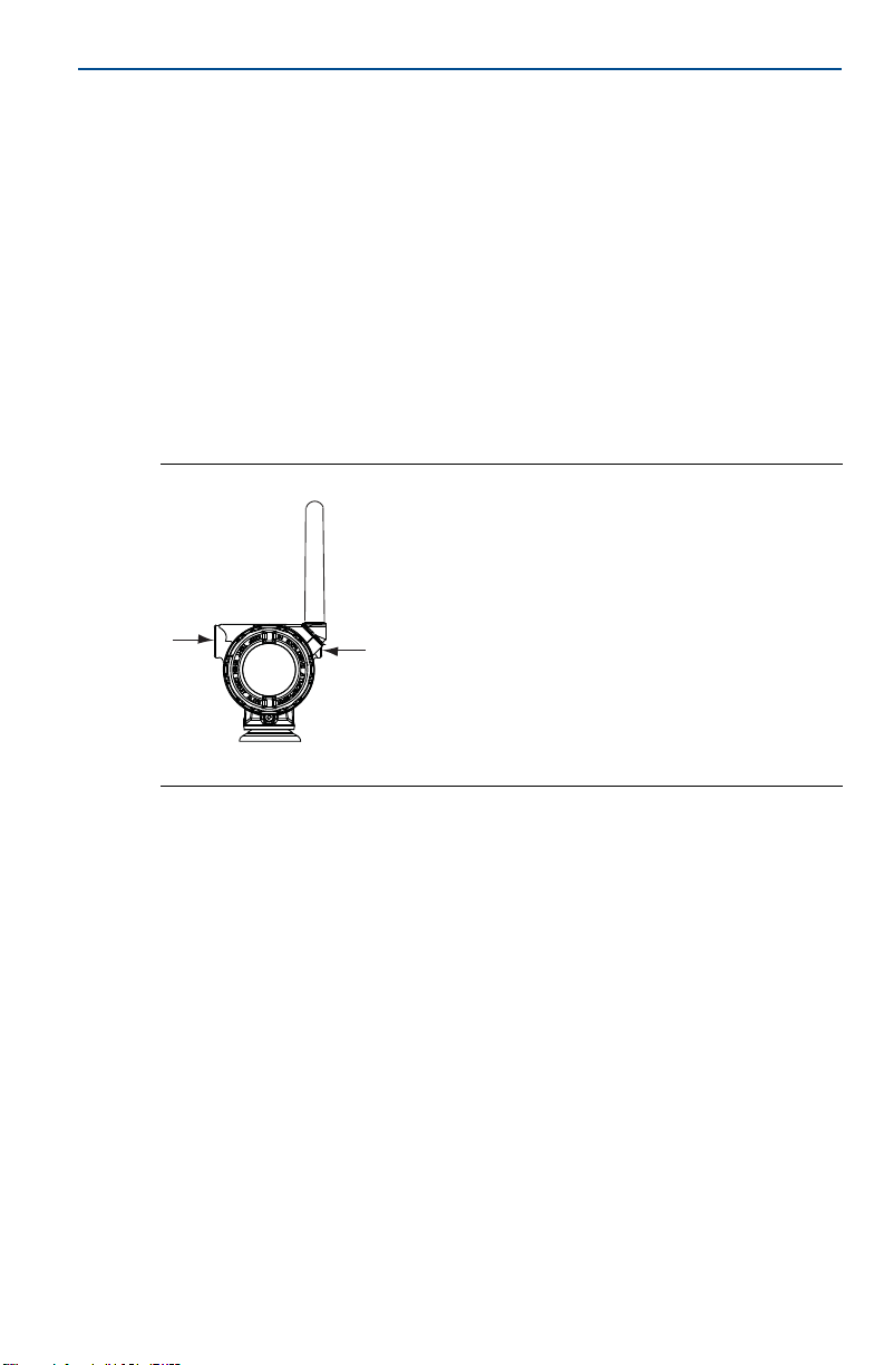
Figure 1. Conduit Entry
1
/2–14 NPT.
Quick Start Guide
A. Conduit entry
2.0 Mount transmitter on a turbine meter or pulse output device
2.1 General considerations
The Rosemount 705 Transmitter and all other wireless devices should not be set
up until after the Smart Wireless Gateway (Gateway) has been installed and is
functioning properly.
The transmitter can be installed in one of two configurations:
Direct mount (D1), where the turbine meter is connected directly to the
transmitter housing’s conduit entry
Remote mount (R1), where the turbine meter is mounted separate from the
transmitter housing, then connected to the transmitter via conduit
Select the installation sequence that corresponds to the mounting
configuration.
3
Page 4
Quick Start Guide
A
C
B
Direct mount
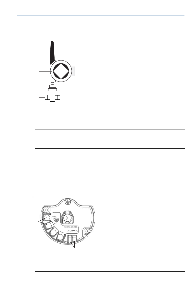
Figure 2. Direct Mount
A
B
C
A. Rosemount 705 Transmitter
B. 1-in. NPT connection to flow meter and two-piece pipe union
C. Turbine meter
Note
Direct mount installation should not be employed when using tubing and connectors such
as Swagelok® fittings.
June 2017
1. Install the turbine meter according to standard installation practices making
sure to use thread sealant on all connections.
2. Attach the turbine meter wiring to the terminals as indicated on the wiring
diagram (Figure 3). This procedure is already included for the D1 (direct
mount) option.
Figure 3. Terminal Block
A. Pulse input connection
®
B. HART
4
C. Terminal block ground connection
terminal connection
Page 5
June 2017
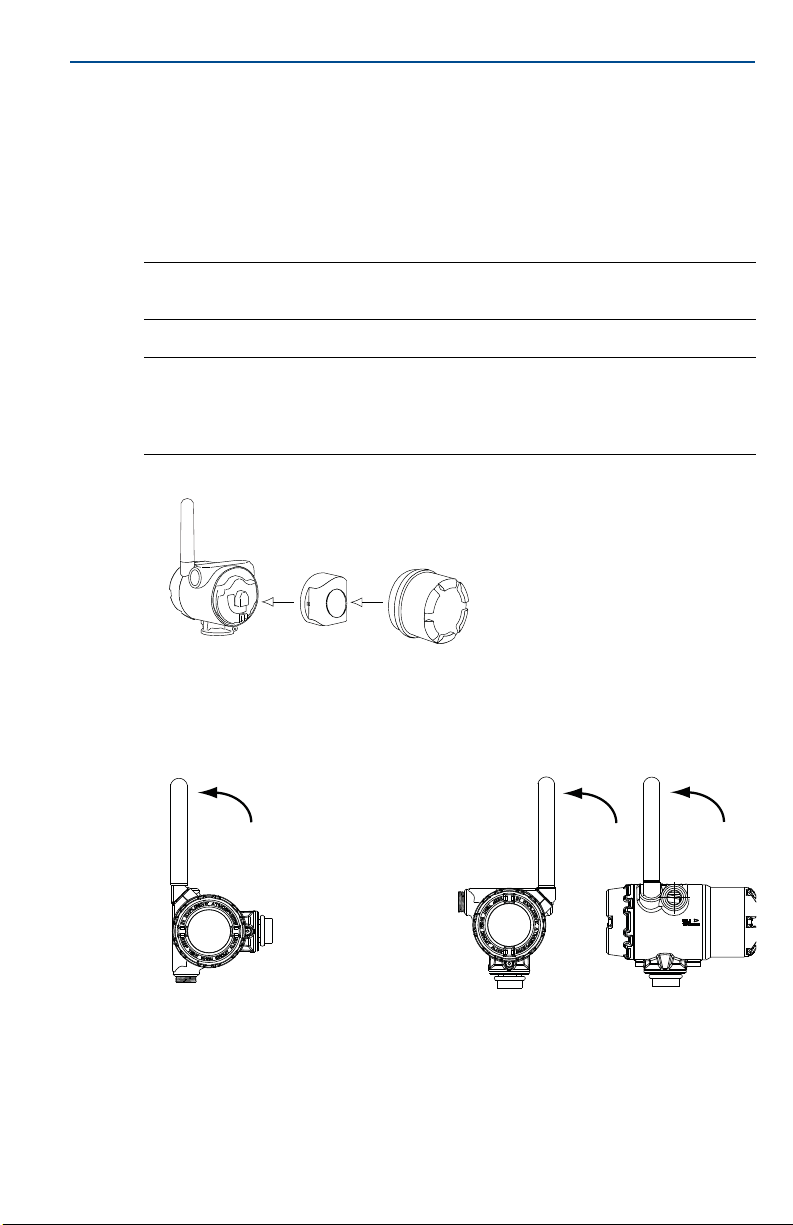
Possible antenna rotation shown.
Antenna rotation allows for best
installation practices in any
configuration.
Quick Start Guide
3. Attach the transmitter housing to the turbine meter using the threaded
conduit entry.
4. Seal threads on 1-in. NPT turbine meter connection. Take union apart and
turn on bottom fitting to turbine meter.
5. Attach mill spec connector to turbine meter pickup.
6. Screw on the remaining union part.
Note
Sealant should already be applied to threads on the D1 (direct mount) option.
Note
Wireless devices should be powered up with the proper join key and net work ID in order of
proximity from the Gateway. Beginning with the closest device to the Gateway will result
in a faster network installation.
7. Connect the black power module.
8. Close the housing cover and tighten to safety specification. Always ensure a
proper seal so that metal touches metal, but do not over tighten.
9. Position antenna vertically, either straight up or straight down.
The antenna should be approximately 3 ft. (0.91 m) from any large structures
or buildings, to allow clear communication to other devices.
5
Page 6
Quick Start Guide
A
B
C
June 2017
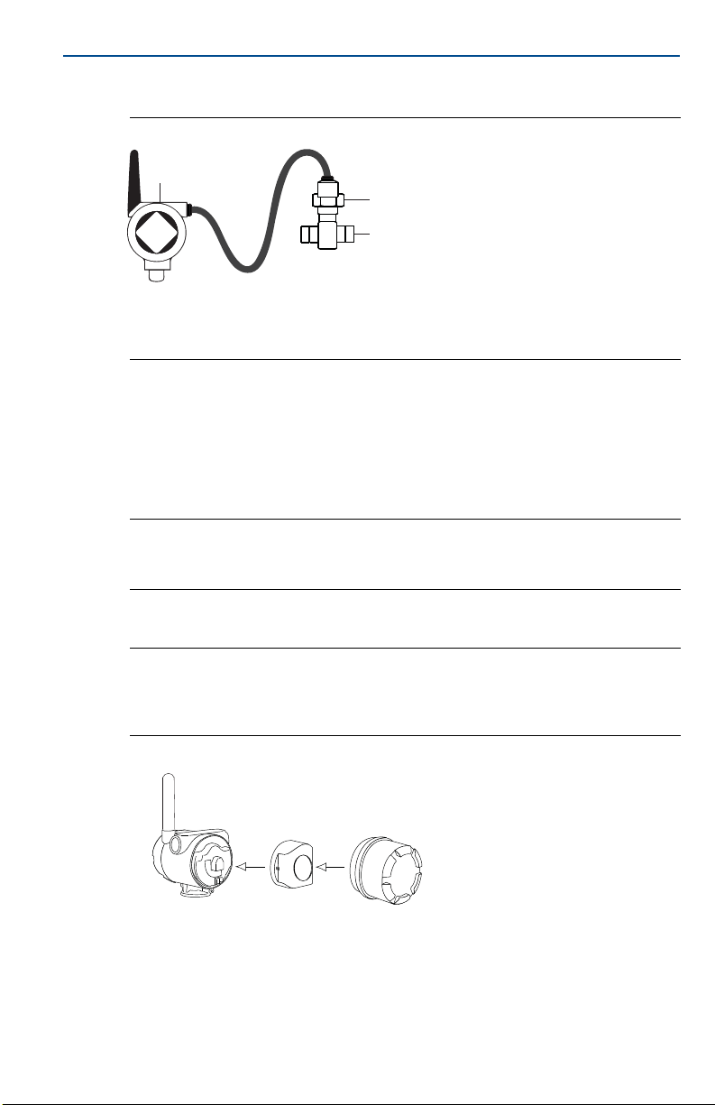
Remote mount
(1)
Figure 4. Remote Mount
A. Rosemount 705 Transmitter
B. 1-in. supplied cable gland adaptor for turbine meter
C. Turbine meter
1. Install the turbine meter according to standard installation practices making
sure to use thread sealant on all connections.
2. Pull the cable connection wiring through the supplied cable gland adaptor
for the turbine meter. Then pull the cable wiring through the transmitter
cable gland.
Note
Pay attention to the orientation of the cable gland to ensure proper connection to
transmitter.
3. Attach the wiring to the terminals as indicated in Figure 3 on page 4.
Note
Wireless devices should be powered up with the proper join key and network ID in order of
proximity from the Gateway. Beginning with the closest device to the Gateway will result
in a faster network installation.
4. Connect the black power module.
5. Close the housing cover and tighten to safety specification. Always ensure a
proper seal so that metal touches metal, but do not over tighten.
1. Included:
(1) Cable gland
(1) Cable gland adaptor for turbine meter
10 ft. of cable connection wiring
6
Page 7

June 2017
6. Position the antenna vertically and straight up.
The antenna should be approximately 3 ft. (0.91 m) from any large structures
or buildings, to allow clear communication to other devices.
2.2 Remote antenna (optional)
The remote antenna option provides flexibility for mounting the Rosemount
705 Transmitter based on wireless connectivity, lightning protection, and
current work practices.
Quick Start Guide
When installing remote mount antennas for the transmitter, always use established safety procedures to avoid
falling or contact with high-power electrical lines.
Install remote antenna components for the transmitter in compliance with local and national electrical codes
and use best practices for lightning protection.
Before installing, consult with the local area electrical inspector, electrical officer, and work area supervisor.
The transmitter remote antenna option is specifically engineered to provide installation flexibility while
optimizing wireless performance and local spectrum approvals. To maintain wireless performance and avoid
non-compliance with spectrum regulations, do not change the length of cable or the antenna type.
If the supplied remote mount antenna kit is not installed per these instructions, Emerson
wireless performance or non-compliance with spectrum regulations.
™
is not responsible for
The remote mount antenna kit includes coaxial sealant that is for the cable
connections, lightning arrestor, and antenna.
Find a location where the remote antenna has optimal wireless performance.
Ideally this will be 15–25 ft. (4.6–7.6 m) above the ground or 6 ft. (2 m) above
obstructions or major infrastructure. To install the remote antenna, use one of
the following procedures. The WN option includes 25 ft. (7.6 m) of cable and the
WJ option includes 10 ft. (3 m) of cable.
WN/WJ remote antenna option
1. Mount the antenna on a 1.5- to 2-in. pipe mast using the supplied mounting
equipment.
2. Connect the lightning arrestor directly to the top of the Rosemount 705
Tra n sm ri tt er.
3. Install the grounding lug, lock washer, and nut on top of lightning arrestor.
7
Page 8

Quick Start Guide
4. Connect the antenna to the lightning arrestor using the supplied LMR-400
coaxial cable ensuring the drip loop is not closer than 1 ft. (0.3 m) from the
lightning arrestor.
5. Use the coaxial sealant to seal each connection between the wireless field
device, lightning arrestor, cable, and antenna.
6. Ensure the mounting mast and lightning arrestor are grounded according to
local/national electrical code.
Note
Any spare lengths of coaxial cable should be placed in 12-in. (0.3 m) coils.
Figure 5. Rosemount 705 Totalizer with Remote Antenna
June 2017
Note: Weatherproofing
The remote mount antenna kit includes coaxial sealant for weatherproofing the cable
connections for the lightning arrestor, antenna, and Rosemount 705 Transmitter. Coaxial
sealant must be applied to ensure performance of the wireless field network. See Figure 6
for details on how to apply coaxial sealant.
Figure 6. Applying Coaxial Sealant to Cable Connections
8
Page 9

June 2017
123
456
7809
D
A
C
B
3.0 Connect to device
Figure 7. Device Connection
A. Communication terminals
B. Field Communicator
C. HART Modem
D. AMS Device Manager
3.1 Field Communicator connections
The power module needs to be installed before the Field Communicator can
interface with the transmitter. This transmitter uses the black power module;
order model number 701PBKKF.
Quick Start Guide
3.2 AMS Wireless Configurator
1. Start AMS Wireless Configurator.
2. In the View menu, select Device Connection View.
3. Double click on the device under the HART modem.
3.3 Field Communicator
1. Turn on the Field Communicator.
2. Tap the HART symbol on the main menu.
The Field Communicator now connects to the device.
4.0 Configure device using guided setup in AMS Device Manager
1. Go to Configure>Guided Setup>Initial Setup.
2. Select Basic Setup and follow the prompts for configuration.
9
3. Consider optional setup, such as Update Rate and Device Display.
Page 10

Quick Start Guide
June 2017
4.1 Join device to network
1. Go to Overview>Shortcuts.
2. Select Configure Update Rate and follow the instructions.
3. Obtain Network ID and Join Key for the wireless network (available in wireless
Gateway).
4. Select Join Device to Network and follow the instructions.
4.2 Wait for device to join network
1. Go to Overview.
2. Wait for communication status to become Connected.
Note
This takes several minutes. Enable Active Advertising on the Gateway to ensure new
devices are able to join the network faster. For more information see the Smart Wireless
Gateway Reference Manual.
5.0 Configure k-factor (calibration factor) for pulse output device or turbine meter
Note
The steps below apply if the k-factor is not preconfigured to the transmitter.
5.1 Primary method
1. Go to Configure>Guided Setup>Basic setup. This will walk you through setting
the device up for first time use.
5.2 Other methods
1. Go to Configure>Manual Setup>Totalizing Options. This is the main interface
for establishing the k-factor as well as other features including low flow cutoff
and manual rollover adjustments.
2. On a HART Handheld, you can configure the k-factor by going to Configure>
Manual Setup>Totalizing Options>Turbine Configuration>k factor.
For more information on these features, see the Rosemount 705 Reference
Manual.
10
Page 11

June 2017
6.0 Product Certifications
Rev 1.1
6.1 European Directive Information
A copy of the EC Declaration of Conformity can be found at the end of the Quick
Start Guide. The most recent revision of the EC Declaration of Conformity can be
found at Emerson.com/Rosemount
6.2 Telecommunication Compliance
All wireless devices require certification to ensure that they adhere to
regulations regarding the use of the RF spectrum. Nearly every country requires
this type of product certification. Emerson is working with governmental
agencies around the world to supply fully compliant products and remove the
risk of violating country directives or laws governing wireless device usage.
6.3 FCC and IC
This device complies with Part 15 of the FCC Rules. Operation is subject to the
following conditions: This device may not cause harmful interference. This
device must accept any interference received, including interference that may
cause undesired operation. This device must be installed to ensure a minimum
antenna separation distance of 20 cm from all persons.
6.4 Ordinary Location Certification from CSA
The transmitter has been examined and tested to determine that the design
meets the basic electrical, mechanical, and fire protection requirements by CSA,
a nationally recognized test laboratory (NRTL) as accredited by the Federal
Occupational Safety and Health Administration (OSHA).
.
Quick Start Guide
6.5 Installing in North America
The US National Electrical Code® (NEC) and the Canadian Electrical Code (CEC)
permit the use of Division marked equipment in Zones and Zone marked
equipment in Divisions. The markings must be suitable for the area
classification, gas, and temperature class. This information is clearly defined in
the respective codes.
USA
I5 USA Intrinsically Safe (IS)
Certificate: CSA 70011131
Standards: FM 3600 – 2011, FM 3610 – 2010, UL Standard 50 – Eleventh Edition, UL
61010-1 – 3
ANSI/ISA-60079-11 (12.02.01) – 2013, ANSI/IEC 60529 – 2004
Markings: IS CL I, DIV 1, GP A, B, C, D T4; Class 1, Zone 0, AEx ia IIC T4 Ga; T4 (–50 °C ≤ T
+70 °C) when installed per Rosemount drawing 00705-1020; Type 4X; IP66
See the table at the end of this section for entity parameters.
rd
Edition, ANSI/ISA-60079-0 (12.00.01) – 2013,
≤
a
11
Page 12

Quick Start Guide
N5 USA Division 2, Nonincendive
Certificate: CSA 70011131
Standards: FM 3600 – 2011, FM 3611 – 2004, UL Standard 50 – Eleventh Edition,
UL 61010-1 (3
Markings: NI CL I, DIV 2, GP A, B, C, D T4; T4 (–50 °C ≤ T
Special Conditions for Safe Use (X):
1. For use only with the Model 701P or Rosemount P/N 753-9220-XXXX Smart Power
Battery Module.
2. The surface resistivity of the antenna is greater than 1 GΩ. To avoid electrostatic
charge build-up, it must not be rubbed or cleaned with solvents or a dry cloth.
Canada
I6 Canada Intrinsically Safe (IS)
Certificate: CSA 70011131
Standards: CAN/CSA C22.2 No. 0-10, CAN/CSA C22.2 No. 94-M91, CSA Std C22.2
No.142-M1987, CAN/CSA-60079-0 - 2011, CAN/CSA-60079-11 - 2014, CSA
Std C22.2 No. 60529 - 2005, CAN/CSA-C22.2 No. 61010-1 - 2012
Markings: IS CL I, DIV 1, GP A, B, C, D T4; Ex ia IIC T4 Ga, T4; T4 (–50 °C ≤ T
when installed per Rosemount drawing 00705-1020; Type 4X; IP66
See the table at the end of this section for entity parameters.
N6 Canada Division 2, Nonincendive
Certificate: CSA 70011131
Standards: CAN/CSA C22.2 No. 0-10, CAN/CSA C22.2 No. 94-M91, CSA Std C22.2 No.
213-M1987 (R2013), CAN/CSA-60079-0 - 2011, CAN/CSA Std C22.2 No.
60529 - 2005, CAN/CSA-C22.2 No. 61010-1 - 2012
Markings: Suitab le for Class 1, Divi sion 2, Gro ups A, B, C, D T4; T4 (–50 °C ≤ Ta ≤ +70 °C);
Type 4X; IP66
Special Conditions for Safe Use (X):
1. For use only with the Model 701P or Rosemount P/N 753-9220-XXXX Smart Power
Battery Module.
2. The surface resistivity of the antenna is greater than 1 GΩ. To avoid electrostatic
charge build-up, it must not be rubbed or cleaned with solvents or a dry cloth.
rd
Edition), ANSI/IEC 60529 – 2004
≤ +70 °C); Type 4X; IP66
a
≤ +70 °C)
a
June 2017
Europe
I1 ATE X Int rinsi c Sa fety
Certificate: Baseefa14ATEX0375X
Standards: EN 60079-0: 2012, EN 60079-11: 2012
Markings: II 1 G Ex ia IIC T4 Ga, T4(–50 °C ≤ T
For use with Rosemount SmartPower
use with Emerson SmartPower option 701PBKKF.
See the table at the end of this section for entity parameters.
Special Conditions for Safe Use (X):
1. The surface resistivity of the antenna is greater than 1 GΩ. To avoid electrostatic
charge build-up, it must not be rubbed or cleaned with solvents or a dry cloth.
2. 2.The Model 701PBKKF Power Module may be replaced in a hazardous area. The Power
Modules have a surface resistivity greater than 1G? and must be properly installed I the
wireless device enclosure. Care must be taken during transportation to and from the
point of installation to prevent electrostatic charge build-up.
12
≤ +70 °C)
™
power module part number 753-9220-0001, or for
a
Page 13

June 2017
3. The 705 enclosure may be made of aluminum alloy and given a protective
polyurethane paint finish; however, care should be taken to protect it from impact or
abrasion if located in a Zone 0 area.
IU ATEX Intrinsic Safet y for Zone 2
Certificate: Baseefa15ATEX0059X
Standards: EN 60079-0: 2012, EN 60079-11: 2012
Markings: II 3 G Ex ic IIC T4 Gc, T4(–50 °C ≤ T
For use with Rosemount SmartPower power module part number 753-9220-0001, or for
use with Emerson SmartPower option 701PBKKF.
See the table at the end of this section for entity parameters.
Special Conditions for Safe Use (X):
1. The surface resistivity of the antenna is greater than 1 GΩ. To avoid electrostatic
charge build-up, it must not be rubbed or cleaned with solvents or a dry cloth.
2. The Model 701PBKKF Power Module may be replaced in a hazardous area. The Power
Modules have a surface resistivity greater than 1G? and must be properly installed I the
wireless device enclosure. Care must be taken during transportation to and from the
point of installation to prevent electrostatic charge build-up.
3. The 705 enclosure may be made of aluminum alloy and given a protective
polyurethane paint finish; however, care should be taken to protect it from impact or
abrasion if located in a Zone 0 area.
International
I7 IECEx Intrinsic Safety
Certificate: IECEx BAS 14.0173X
Standards: IEC 60079-0: 2011, IEC 60079-11: 2011
Markings: Ex ia IIC T4 Ga, T4 (–50 °C ≤ T
For use with Rosemount SmartPower power module part number 753-9220-0001, or for
use with Emerson SmartPower option 701PBKKF.
See the table at the end of this section for entity parameters.
Special Conditions for Safe Use (X):
1. The surface resistivity of the antenna is greater than 1 GΩ. To avoid electrostatic
charge build-up, it must not be rubbed or cleaned with solvents or a dry cloth.
2. The Model 701PBKKF Power Module may be replaced in a hazardous area. The Power
Modules have a surface resistivity greater than 1G? and must be properly installed I the
wireless device enclosure. Care must be taken during transportation to and from the
point of installation to prevent electrostatic charge build-up.
3. The 705 enclosure may be made of aluminum alloy and given a protective
polyurethane paint finish; however, care should be taken to protect it from impact or
abrasion if located in a Zone 0 area.
≤ +70 °C)
a
≤ +70 °C)
a
Quick Start Guide
IY IECEx Intrinsic Safety for Zone 2
Certificate: IECEx BAS 14.0173X
Standards: IEC 60079-0: 2011, IEC 60079-11: 2011
Markings: Ex ic IIC T4 Gc, T4 (–60 °C ≤ T
≤ +70 °C)
a
For use with Rosemount SmartPower power module part number 753-9220-0001, or for
use with Emerson SmartPower option 701PBKKF.
See the table at the end of this section for entity parameters.
13
Page 14

Quick Start Guide
Special Conditions for Safe Use (X):
1. The sur face resistivity of the antenna is greater than 1 GΩ. To avoid electrostatic
charge build-up, it must not be rubbed or cleaned with solvents or a dry cloth.
2. The Model 701PBKKF Power Module may be replaced in a hazardous area. The Power
Modules have a surface resistivity greater than 1G? and must be properly installed I the
wireless device enclosure. Care must be taken during transportation to and from the
point of installation to prevent electrostatic charge build-up.
3. The 705 enclosure may be made of aluminum alloy and given a protective
polyurethane paint finish; however, care should be taken to protect it from impact or
abrasion if located in a Zone 0 area.
Brazil
I2 INMETRO Intrinsic Safety
Certificate: UL-BR 17.0019X
Standards: ABNT NBR IEC 60079-0:2008 + Errata 1:2011, ABNT NBR IEC 60079-11:2009
Markings: Ex ia IIC T4 Ga, T4 (–60 °C ≤ T
≤ +70 °C)
a
See the table at the end of this section for entity parameters.
Special Condition for Safe Use (X):
1. See certificate for special conditions.
EAC - Belarus, Kazakhstan, Russia
IM Technical Regulation Customs Union (EAC) Intrinsic Safety
Certificate: TC RU C-US.MIO62.B.03122
Markings: 0Ex ia IIC T4 Ga X, T4 (–60 °C ≤ T
See the table at the end of this section for entity parameters.
Special Condition for Safe Use (X):
1. See certificate for special conditions.
≤ +70 °C)
a
June 2017
14
Turbine meter terminal output parameters Turbine meter terminal input parameters
VOC/UO = 2.5 V V
ISC/IO = 253 μA I
P
= 640 μW P
MAX/PO
MAX/Ui
MAX/Ii
MAX/Pi
= 10 V
= 1 mA
= 1 mW
Ca/CO = 2.9 μF Ci = 2.2 nF
La/LO = 500 mH Li = 4.7 mH
Page 15

June 2017
EU Declaration of Conformity
No: RMD 1105 Rev. D
Page 1 of 3
We,
Rosemount, Inc.
8200 Market Boulevard
Chanhassen, MN 55317-9685
USA
declare under our sole responsibility that the product,
Rosemount 705 Wireless Totalizer Transmitter
manufactured by,
Rosemount, Inc.
8200 Market Boulevard
Chanhassen, MN 55317-9685
USA
to which this declaration relates, is in conformity with the provisions of the European Union
Directives, including the latest amendments, as shown in the attached schedule.
Assumption of conformity is based on the application of the harmonized standards and, when
applicable or required, a European Union notified body certification, as shown in the attached
schedule.
Vice President of Global Quality
Chris LaPoint
6-June-2017
Figure 8. Rosemount 705 Declaration of Conformity
Quick Start Guide
(signature)
(name)
(function)
(date of issue)
15
Page 16

Quick Start Guide
EU Declaration of Conformity
No: RMD 1105 Rev. D
Page 2 of 3
EMC Directive (2014/30/EU)
Harmonized Standards:
EN 61326-1: 2013
Radio Equipment Directive (RED) (2014/53/EU)
Harmonized Standards:
EN 300 328 V2.1.1
EN 301 489-1 V2.2.0
EN 301 489-17 V3.2.0
EN 61010-1: 2010
EN 62479: 2010
ATEX Directive (2014/34/EU)
Baseefa14ATEX0375X – Intrinsic Safety Certificate (Ex ia)
Equipment Group II, Category 1 G
Ex ia IIC T4 Ga
Harmonized Standards:
EN 60079-0: 2012
EN 60079-11: 2012
Baseefa15ATEX0059X – Intrinsic Safety Certificate (Ex ic)
Equipment Group II, Category 3 G
Ex ic IIC T4 Gc
Harmonized Standards:
EN 60079-0: 2012
EN 60079-11: 2012
June 2017
16
Page 17

June 2017
EU Declaration of Conformity
No: RMD 1105 Rev. D
Page 3 of 3
ATEX Notified Body
SGS Baseefa Limited [Notified Body Number: 1180]
Rockhead Business Park
Staden Lane
Buxton, Derbyshire SK17 9RZ
United Kingdom
ATEX Notified Body for Quality Assurance
SGS Baseefa Limited [Notified Body Number: 1180]
Rockhead Business Park
Staden Lane
Buxton, Derbyshire SK17 9RZ
United Kingdom
Quick Start Guide
17
Page 18

Quick Start Guide
ᴹ
China RoHS
㇑᧗⢙䍘䎵䗷ᴰབྷ⎃ᓖ䲀٬Ⲵ䜘Ԧරࡇ㺘
Rosemount 705
Rosemount 705
List of Parts with China RoHS Concentration above MCVs
䜘Ԧ〠
Part Name
ᴹᇣ⢙䍘䍘/ Hazardous Substances
䫵
Lead
(Pb)
⊎
Mercury
(Hg)
䭹
Cadmium
(Cd)
ޝԧ䬜䬜
Hexavalent
Chromium
(Cr +6)
ཊⓤ㚄㚄㤟
Polybrominated
biphenyls
(PBB)
ཊⓤ㚄㚄㤟䟊
Polybrominated
diphenyl ethers
(PBDE)
⭥ᆀ㓴Ԧ
Electronics
Assembly
X O O O O
O
༣փ㓴Ԧ
Housing
Assembly
X O O X O
O
ᵜ㺘Ṭ㌫ᦞ
SJ/T11364
Ⲵ㿴ᇊ㘼ࡦ
This table is proposed in accordance with the provision of SJ/T11364.
O:
Ѫ䈕䜘ԦⲴᡰᴹ൷䍘ᶀᯉѝ䈕ᴹᇣ⢙䍘Ⲵ䟿൷վҾ
GB/T 26572
ᡰ㿴ᇊⲴ䲀䟿㾱≲
O: Indicate that said hazardous substance in all of the homogeneous materials for this part is below the limit requirement of
GB/T 26572.
X:
Ѫ൘䈕䜘Ԧᡰ֯⭘Ⲵᡰᴹ൷䍘ᶀᯉ䟼ˈ㠣ቁᴹа㊫൷䍘ᶀᯉѝ䈕ᴹᇣ⢙䍘Ⲵ䟿儈Ҿ
GB/T 26572
ᡰ㿴ᇊⲴ䲀䟿㾱≲
X: Indicate that said hazardous substance contained in at least one of the ho mogeneous materials us ed for this part is abov e
the limit requirement of GB/T 26572.
June 2017
18
Page 19

June 2017
Quick Start Guide
19
Page 20

Global Headquarters
Emerson Automation Solutions
6021 Innovation Blvd.
Shakopee, MN 55379, USA
+1 800 999 9307 or +1 952 906 8888
+1 952 949 7001
RFQ.RMD-RCC@Emerson.com
North America Regional Office
Emerson Automation Solutions
8200 Market Blvd.
Chanhassen, MN 55317, USA
+1 800 999 9307 or +1 952 906 8888
+1 952 949 7001
RMT-NA.RCCRFQ@Emerson.com
Latin America Regional Office
Emerson Automation Solutions
1300 Concord Terrace, Suite 400
Sunrise, FL 33323, USA
+1 954 846 5030
+1 954 846 5121
RFQ.RMD-RCC@Emerson.com
Europe Regional Office
Emerson Automation Solutions
Neuhofstrasse 19a P.O. Box 1046
CH 6340 Baar
Switzerland
+41 (0) 41 768 6111
+41 (0) 41 768 6300
RFQ.RMD-RCC@Emerson.com
Asia Pacific Regional Office
Emerson Automation Solutions
1 Pandan Crescent
Singapore 128461
+65 6777 8211
+65 6777 0947
Enquiries@AP.Emerson.com
Middle East and Africa Regional Office
Emerson Automation Solutions
Emerson FZE P.O. Box 17033
Jebel Ali Free Zone - South 2
Dubai, United Arab Emi rates
+971 4 8118100
+971 4 8865465
RFQ.RMTMEA@Emerson.com
*00825-0200-4705*
Quick Start Guide
00825-0200-4705, Rev CB
Linkedin.com/company/Emerson-Automation-Solutions
Twitter.com/Rosemount_News
Facebook.com/Rosemount
Youtube.com/us er/RosemountMeasur ement
Google.com/+RosemountMeasurement
Standard Terms and Conditions of Sale can be found on the Term s
and Conditions of Sale page.
The Emerson logo is a trademark and service mark of Emerson
Electric Co.
SmartPower, Rosemount, and Rosemount logotype are trademarks
of Emerson .
Swagelok is a registered trademark of Swagelok Company.
HART is a registered trademark of the FieldComm Group.
National Electrical Code is a registered trademark of National Fire
Protection Association, Inc.
All other marks are the propert y of their respective owners.
© 2017 Emerson. All rights reser ved.
June 2017
 Loading...