

Page 1
Reference Manual
00809-0200-4702, Rev EA
June 2018
Rosemount™ 702 Wireless Discrete Transmitter
Page 2

Page 3

Reference Manual
00809-0200-4702, Rev EA
Contents
1Section 1: Introduction
Contents
June 2018
1.1 Using this manual . . . . . . . . . . . . . . . . . . . . . . . . . . . . . . . . . . . . . . . . . . . . . . . . . . . . . . . . . . . . . . . . . 1
1.2 Models covered . . . . . . . . . . . . . . . . . . . . . . . . . . . . . . . . . . . . . . . . . . . . . . . . . . . . . . . . . . . . . . . . . . . 2
1.2.1 Rosemount 702DX22 Wireless Discrete Transmitter . . . . . . . . . . . . . . . . . . . . . . . . . . . . . 2
1.2.2 Rosemount 702DX61 Wireless Discrete Transmitter for liquid hydrocarbon leak
detection . . . . . . . . . . . . . . . . . . . . . . . . . . . . . . . . . . . . . . . . . . . . . . . . . . . . . . . . . . . . . . . . . . . 2
1.2.3 Rosemount 702DX32 Wireless Discrete Transmitter . . . . . . . . . . . . . . . . . . . . . . . . . . . . . 2
1.2.4 Rosemount 702DX42 Wireless Discrete Transmitter . . . . . . . . . . . . . . . . . . . . . . . . . . . . . 2
1.3 Transmitter overview . . . . . . . . . . . . . . . . . . . . . . . . . . . . . . . . . . . . . . . . . . . . . . . . . . . . . . . . . . . . . . 3
1.3.1 Functions of the transmitter. . . . . . . . . . . . . . . . . . . . . . . . . . . . . . . . . . . . . . . . . . . . . . . . . . . 3
1.3.2 Wireless considerations. . . . . . . . . . . . . . . . . . . . . . . . . . . . . . . . . . . . . . . . . . . . . . . . . . . . . . . 3
1.3.3 Choosing an installation location and position. . . . . . . . . . . . . . . . . . . . . . . . . . . . . . . . . . . 4
1.3.4 Electrical. . . . . . . . . . . . . . . . . . . . . . . . . . . . . . . . . . . . . . . . . . . . . . . . . . . . . . . . . . . . . . . . . . . . 5
1.3.5 Verifying operating atmosphere . . . . . . . . . . . . . . . . . . . . . . . . . . . . . . . . . . . . . . . . . . . . . . . 5
1.4 Product recycling/disposal. . . . . . . . . . . . . . . . . . . . . . . . . . . . . . . . . . . . . . . . . . . . . . . . . . . . . . . . . . 6
2Section 2: Configuration: Models 702DX22 and 702DX61
2.1 Safety messages. . . . . . . . . . . . . . . . . . . . . . . . . . . . . . . . . . . . . . . . . . . . . . . . . . . . . . . . . . . . . . . . . . . 7
2.1.1 Connecting the switches. . . . . . . . . . . . . . . . . . . . . . . . . . . . . . . . . . . . . . . . . . . . . . . . . . . . . . 7
2.2 Configuring the Device Sensor . . . . . . . . . . . . . . . . . . . . . . . . . . . . . . . . . . . . . . . . . . . . . . . . . . . . . . 8
2.3 Configuring on the bench . . . . . . . . . . . . . . . . . . . . . . . . . . . . . . . . . . . . . . . . . . . . . . . . . . . . . . . . . . 8
2.4 Configuring the device network . . . . . . . . . . . . . . . . . . . . . . . . . . . . . . . . . . . . . . . . . . . . . . . . . . . . . 9
2.4.1 Configuring transmitter with dry contact inputs, measurement option code 22
(702DX22) . . . . . . . . . . . . . . . . . . . . . . . . . . . . . . . . . . . . . . . . . . . . . . . . . . . . . . . . . . . . . . . . . . 9
2.4.2 Configuring transmitter with liquid hydrocarbon detection, measurement option
code 61(702DX61). . . . . . . . . . . . . . . . . . . . . . . . . . . . . . . . . . . . . . . . . . . . . . . . . . . . . . . . . . 10
2.5 HART menu tree. . . . . . . . . . . . . . . . . . . . . . . . . . . . . . . . . . . . . . . . . . . . . . . . . . . . . . . . . . . . . . . . . . 11
2.5.1 Dry contact inputs, measurement option code 22 (702DX22) . . . . . . . . . . . . . . . . . . . . 11
2.5.2 Liquid hydrocarbon detection, measurement option code 61(702DX61) . . . . . . . . . . 12
2.5.3 Fast Key sequence . . . . . . . . . . . . . . . . . . . . . . . . . . . . . . . . . . . . . . . . . . . . . . . . . . . . . . . . . . 13
2.6 Remove power module . . . . . . . . . . . . . . . . . . . . . . . . . . . . . . . . . . . . . . . . . . . . . . . . . . . . . . . . . . . 13
Content s
1
Page 4

Contents
June 2018
Reference Manual
00809-0200-4702, Rev EA
3Section 3: Mounting, Wiring Switches, and Sensors: Models 702DX22
and 702DX61
3.1 Safety messages. . . . . . . . . . . . . . . . . . . . . . . . . . . . . . . . . . . . . . . . . . . . . . . . . . . . . . . . . . . . . . . . . . 15
3.2 Installing the transmitter . . . . . . . . . . . . . . . . . . . . . . . . . . . . . . . . . . . . . . . . . . . . . . . . . . . . . . . . . . 16
3.2.1 Direct mount configuration . . . . . . . . . . . . . . . . . . . . . . . . . . . . . . . . . . . . . . . . . . . . . . . . . . 16
3.2.2 Remote mount configuration . . . . . . . . . . . . . . . . . . . . . . . . . . . . . . . . . . . . . . . . . . . . . . . . 18
3.3 Wiring switches and sensors . . . . . . . . . . . . . . . . . . . . . . . . . . . . . . . . . . . . . . . . . . . . . . . . . . . . . . . 19
3.3.1 Dry contact inputs, measurement option code 22 (702DX22) . . . . . . . . . . . . . . . . . . . . 19
3.3.2 Wireless output specifications. . . . . . . . . . . . . . . . . . . . . . . . . . . . . . . . . . . . . . . . . . . . . . . . 19
3.3.3 Liquid hydrocarbon detection, measurement option code 61(702DX61) . . . . . . . . . . 21
3.4 LCD display . . . . . . . . . . . . . . . . . . . . . . . . . . . . . . . . . . . . . . . . . . . . . . . . . . . . . . . . . . . . . . . . . . . . . . 23
3.5 Grounding the transmitter. . . . . . . . . . . . . . . . . . . . . . . . . . . . . . . . . . . . . . . . . . . . . . . . . . . . . . . . . 24
4Section 4: Commissioning: Models 702DX22 and 702DX61
4.1 Safety messages. . . . . . . . . . . . . . . . . . . . . . . . . . . . . . . . . . . . . . . . . . . . . . . . . . . . . . . . . . . . . . . . . . 27
4.2 Configuring the transmitter to communicate with the wireless network. . . . . . . . . . . . . . . . . 28
4.3 AMS Wireless Configurator . . . . . . . . . . . . . . . . . . . . . . . . . . . . . . . . . . . . . . . . . . . . . . . . . . . . . . . . 28
4.4 Field Communicator . . . . . . . . . . . . . . . . . . . . . . . . . . . . . . . . . . . . . . . . . . . . . . . . . . . . . . . . . . . . . . 28
4.5 Verifying operation . . . . . . . . . . . . . . . . . . . . . . . . . . . . . . . . . . . . . . . . . . . . . . . . . . . . . . . . . . . . . . . 29
4.5.1 AMS Wireless Configurator. . . . . . . . . . . . . . . . . . . . . . . . . . . . . . . . . . . . . . . . . . . . . . . . . . . 31
5Section 5: Operation and Maintenance: Models 702DX22 and 702DX61
5.1 Safety Messages. . . . . . . . . . . . . . . . . . . . . . . . . . . . . . . . . . . . . . . . . . . . . . . . . . . . . . . . . . . . . . . . . . 33
5.2 Discrete input from switches and sensors. . . . . . . . . . . . . . . . . . . . . . . . . . . . . . . . . . . . . . . . . . . . 34
5.2.1 Dry contact inputs, measurement option code 22 (702DX22) . . . . . . . . . . . . . . . . . . . . 34
5.2.2 Wireless output specifications. . . . . . . . . . . . . . . . . . . . . . . . . . . . . . . . . . . . . . . . . . . . . . . . 34
5.2.3 Liquid hydrocarbon detection, measurement option code 61 (702DX61) . . . . . . . . . . 36
5.3 LCD display screen messages . . . . . . . . . . . . . . . . . . . . . . . . . . . . . . . . . . . . . . . . . . . . . . . . . . . . . . 40
5.3.1 Startup screen sequence. . . . . . . . . . . . . . . . . . . . . . . . . . . . . . . . . . . . . . . . . . . . . . . . . . . . . 40
5.3.2 Diagnostic button screen sequence . . . . . . . . . . . . . . . . . . . . . . . . . . . . . . . . . . . . . . . . . . . 42
5.3.3 Network connection status screens . . . . . . . . . . . . . . . . . . . . . . . . . . . . . . . . . . . . . . . . . . . 43
5.3.4 Device diagnostic screens. . . . . . . . . . . . . . . . . . . . . . . . . . . . . . . . . . . . . . . . . . . . . . . . . . . . 45
5.4 Replacing the power module. . . . . . . . . . . . . . . . . . . . . . . . . . . . . . . . . . . . . . . . . . . . . . . . . . . . . . . 48
5.5 Service support. . . . . . . . . . . . . . . . . . . . . . . . . . . . . . . . . . . . . . . . . . . . . . . . . . . . . . . . . . . . . . . . . . . 49
2
Contents
Page 5

Reference Manual
00809-0200-4702, Rev EA
6Section 6: Configuration: Models 702DX32 and 702DX42
7Section 7: Mounting, Wiring Switches, and Output Circuits: Models
Contents
June 2018
6.1 Safety messages. . . . . . . . . . . . . . . . . . . . . . . . . . . . . . . . . . . . . . . . . . . . . . . . . . . . . . . . . . . . . . . . . . 51
6.1.1 Ensuring proper switch connections. . . . . . . . . . . . . . . . . . . . . . . . . . . . . . . . . . . . . . . . . . . 52
6.2 Discrete channel configuration. . . . . . . . . . . . . . . . . . . . . . . . . . . . . . . . . . . . . . . . . . . . . . . . . . . . . 52
6.3 Device network configuration. . . . . . . . . . . . . . . . . . . . . . . . . . . . . . . . . . . . . . . . . . . . . . . . . . . . . . 52
6.3.1 Dry contact inputs, measurement option code 32, 42
(Models 702DX32 and 702DX42) . . . . . . . . . . . . . . . . . . . . . . . . . . . . . . . . . . . . . . . . . . . . . 53
6.4 HART menu tree. . . . . . . . . . . . . . . . . . . . . . . . . . . . . . . . . . . . . . . . . . . . . . . . . . . . . . . . . . . . . . . . . . 55
6.4.1 Fast Key sequence . . . . . . . . . . . . . . . . . . . . . . . . . . . . . . . . . . . . . . . . . . . . . . . . . . . . . . . . . . 58
6.5 Removing the power module . . . . . . . . . . . . . . . . . . . . . . . . . . . . . . . . . . . . . . . . . . . . . . . . . . . . . . 58
702DX32 and 702DX42
7.1 Safety messages. . . . . . . . . . . . . . . . . . . . . . . . . . . . . . . . . . . . . . . . . . . . . . . . . . . . . . . . . . . . . . . . . . 59
7.2 Installing the transmitter . . . . . . . . . . . . . . . . . . . . . . . . . . . . . . . . . . . . . . . . . . . . . . . . . . . . . . . . . . 60
7.2.1 Direct mount. . . . . . . . . . . . . . . . . . . . . . . . . . . . . . . . . . . . . . . . . . . . . . . . . . . . . . . . . . . . . . . 60
7.2.2 Remote mount . . . . . . . . . . . . . . . . . . . . . . . . . . . . . . . . . . . . . . . . . . . . . . . . . . . . . . . . . . . . . 62
7.3 Wiring switches and sensors . . . . . . . . . . . . . . . . . . . . . . . . . . . . . . . . . . . . . . . . . . . . . . . . . . . . . . . 63
7.3.1 Dry contact inputs, measurement option code 32, 42 (702DX32, 702DX42) . . . . . . . 63
7.3.2 Dry contact switch inputs . . . . . . . . . . . . . . . . . . . . . . . . . . . . . . . . . . . . . . . . . . . . . . . . . . . . 63
7.3.3 Output circuits, measurement option code 42 (702DX42) . . . . . . . . . . . . . . . . . . . . . . . 65
7.3.4 Safety shower and eye wash monitoring . . . . . . . . . . . . . . . . . . . . . . . . . . . . . . . . . . . . . . . 67
7.4 LCD display . . . . . . . . . . . . . . . . . . . . . . . . . . . . . . . . . . . . . . . . . . . . . . . . . . . . . . . . . . . . . . . . . . . . . . 70
7.5 Grounding the transmitter. . . . . . . . . . . . . . . . . . . . . . . . . . . . . . . . . . . . . . . . . . . . . . . . . . . . . . . . . 71
8Section 8: Commissioning: Models 702DX32 and 702DX42
8.1 Safety messages. . . . . . . . . . . . . . . . . . . . . . . . . . . . . . . . . . . . . . . . . . . . . . . . . . . . . . . . . . . . . . . . . . 73
8.2 Configuring wireless network communication . . . . . . . . . . . . . . . . . . . . . . . . . . . . . . . . . . . . . . . 74
8.3 Verifying operation . . . . . . . . . . . . . . . . . . . . . . . . . . . . . . . . . . . . . . . . . . . . . . . . . . . . . . . . . . . . . . . 74
8.3.1 AMS Wireless Configurator. . . . . . . . . . . . . . . . . . . . . . . . . . . . . . . . . . . . . . . . . . . . . . . . . . . 77
Content s
3
Page 6

Contents
June 2018
Reference Manual
00809-0200-4702, Rev EA
9Section 9: Operation and Maintenance: Models 702DX32 and 702DX42
9.1 Safety messages. . . . . . . . . . . . . . . . . . . . . . . . . . . . . . . . . . . . . . . . . . . . . . . . . . . . . . . . . . . . . . . . . . 79
9.2 Discrete input from switches. . . . . . . . . . . . . . . . . . . . . . . . . . . . . . . . . . . . . . . . . . . . . . . . . . . . . . . 80
9.2.1 Dry contact inputs, measurement option code 32, 42 (702DX32, 702DX42) . . . . . . . 80
9.2.2 Wireless output specifications. . . . . . . . . . . . . . . . . . . . . . . . . . . . . . . . . . . . . . . . . . . . . . . . 80
9.2.3 Momentary discrete inputs, measurement option code 32 and 42
(702DX32, 702DX42) . . . . . . . . . . . . . . . . . . . . . . . . . . . . . . . . . . . . . . . . . . . . . . . . . . . . . . . 82
9.3 Discrete output circuits . . . . . . . . . . . . . . . . . . . . . . . . . . . . . . . . . . . . . . . . . . . . . . . . . . . . . . . . . . . 86
9.4 Modbus and OPC mapping . . . . . . . . . . . . . . . . . . . . . . . . . . . . . . . . . . . . . . . . . . . . . . . . . . . . . . . . 90
9.5 Interpreting the LCD display screen messages. . . . . . . . . . . . . . . . . . . . . . . . . . . . . . . . . . . . . . . . 90
9.5.1 Startup screen sequence. . . . . . . . . . . . . . . . . . . . . . . . . . . . . . . . . . . . . . . . . . . . . . . . . . . . . 90
9.5.2 Diagnostic button screen sequence . . . . . . . . . . . . . . . . . . . . . . . . . . . . . . . . . . . . . . . . . . . 92
9.5.3 Network connection status screens . . . . . . . . . . . . . . . . . . . . . . . . . . . . . . . . . . . . . . . . . . . 93
9.5.4 Device diagnostic screens. . . . . . . . . . . . . . . . . . . . . . . . . . . . . . . . . . . . . . . . . . . . . . . . . . . . 95
9.6 Replacing the power module. . . . . . . . . . . . . . . . . . . . . . . . . . . . . . . . . . . . . . . . . . . . . . . . . . . . . . . 97
9.7 Service support. . . . . . . . . . . . . . . . . . . . . . . . . . . . . . . . . . . . . . . . . . . . . . . . . . . . . . . . . . . . . . . . . . . 98
AAppendix A: Reference Data
A.1 Product Certifications . . . . . . . . . . . . . . . . . . . . . . . . . . . . . . . . . . . . . . . . . . . . . . . . . . . . . . . . . . . . . 99
A.2 Ordering Information, Specifications, and Drawings . . . . . . . . . . . . . . . . . . . . . . . . . . . . . . . . . . 99
BAppendix B: High Gain Remote Antenna Option
B.1 Safety messages. . . . . . . . . . . . . . . . . . . . . . . . . . . . . . . . . . . . . . . . . . . . . . . . . . . . . . . . . . . . . . . . . 101
B.2 Functional specifications . . . . . . . . . . . . . . . . . . . . . . . . . . . . . . . . . . . . . . . . . . . . . . . . . . . . . . . . . 102
B.3 Installation considerations. . . . . . . . . . . . . . . . . . . . . . . . . . . . . . . . . . . . . . . . . . . . . . . . . . . . . . . .103
B.4 Transient/lightning considerations . . . . . . . . . . . . . . . . . . . . . . . . . . . . . . . . . . . . . . . . . . . . . . . . 103
B.5 Dimensional drawings . . . . . . . . . . . . . . . . . . . . . . . . . . . . . . . . . . . . . . . . . . . . . . . . . . . . . . . . . . . 104
B.6 Installing the high gain remote antenna . . . . . . . . . . . . . . . . . . . . . . . . . . . . . . . . . . . . . . . . . . . . 105
CAppendix C: Safety Shower Monitoring
C.1 Installation instructions . . . . . . . . . . . . . . . . . . . . . . . . . . . . . . . . . . . . . . . . . . . . . . . . . . . . . . . . . . 109
C.2 Installation drawings . . . . . . . . . . . . . . . . . . . . . . . . . . . . . . . . . . . . . . . . . . . . . . . . . . . . . . . . . . . . . 111
4
Contents
Page 7

Reference Manual
NOTICE
00809-0200-4702, Rev EA
Rosemount™ 702 Wireless Discrete
Transmitter
Read this manual before working with the product. For personal and system safety, and for optimum
product performance, make sure to thoroughly understand the contents before installing, using, or
maintaining this product.
The United States has two toll-free assistance numbers and one international number.
Customer Central
1 800 999 9307 (7:00 a.m. to 7:00 p.m. CST)
National Response Center
1 800 654 7768 (24 hours a day)
Equipment service needs
International
1 952 906 8888
The products described in this document are NOT designed for nuclear-qualified applications.
Using non-nuclear qualified products in applications that require nuclear-qualified hardware or
products may cause inaccurate readings.
For information on Rosemount nuclear-qualified products, contact an Emerson
Title Page
June 2018
™
Sales Representative.
Title Page
Explosions could result in death or serious injury.
Installation of this transmitter in an explosive environment must be in accordance with the
appropriate local, national, and international standards, codes, and practices.
Review the approvals section of this manual for any restrictions associated with a safe installation.
Before connecting a Field Communicator in an explosive atmosphere, ensure the instruments are
installed in accordance with intrinsically safe or non-incendive field wiring practices.
Process leaks may cause harm or result in death.
Install and tighten process connectors before applying pressure.
Electrical shock can result in death or serious injury.
Avoid contact with the leads and terminals. High voltage that may be present on leads can cause
electrical shock.
5
Page 8

Title Page
June 2018
Reference Manual
00809-0200-4702, Rev EA
The Rosemount 702 Transmitter and all other wireless devices should be installed only after the
Emerson Wireless Gateway has been installed and is functioning properly. Wireless devices should also
be powered up in order of proximity from the Gateway, beginning with the closest. This will result in a
simpler and faster network installation.
Shipping considerations for wireless products.
The unit was shipped to you without the power module installed. Remove the power module prior to
shipping.
Each power module contains two “C” size primary lithium batteries. Primary lithium batteries are
regulated in transportation by the U. S. Department of Transportation, and are also covered by IATA
(International Air Transport Association), ICAO (International Civil Aviation Organization), and ARD
(European Ground Transportation of Dangerous Goods). It is the responsibility of the shipper to ensure
compliance with these or any other local requirements. Consult current regulations and requirements
before shipping.
The power module with the wireless unit contains two “C” size primary lithium/thionyl chloride
batteries. Each battery contains approximately 2.5 grams of lithium, for a total of 5 grams in each pack.
Under normal conditions, the battery materials are self-contained and are not reactive as long as the
batteries and the pack integrity are maintained. Care should be taken to prevent thermal, electrical, or
mechanical damage. Contacts should be protected to prevent premature discharge.
Battery hazards remain when cells are discharged.
Power modules should be stored in a clean and dry area. For maximum battery life, storage
temperature should not exceed 30 °C.
The power module has surface resistivity greater than one gigaohm and must be properly installed in
the wireless device enclosure. Care must be taken during transportation to and from the point of
installation to prevent electrostatic charge build-up.
6
Title Page
Page 9

Reference Manual
00809-0200-4702, Rev EA
Section 1 Introduction
1.1 Using this manual
The sections in this manual provide information on installing, operating, and maintaining the
Rosemount
702DX22 and Rosemount 702DX61 models. The Rosemount 702DX22 is the legacy 702 Transmitter
that has discrete input function only. The Rosemount 702DX61 is a special version for liquid hydrocarbon
leak detection with Tyco
702DX32 and Rosemount 702DX42 models. The Rosemount 702DX32 has all of the functionality of the
702DX22, with the addition of momentary discrete input sensing and counting. The 702DX42 adds the
capability of discrete output switching.
Model number Functionality Manual sections
702DX22 Two channel discrete input 1, 2, 3, 4, 5
702DX61 One channel for Tyco TraceTek liquid hydrocarbon leak detection 1, 2, 3, 4, 5
702DX32
™
702 Wireless Discrete Transmitter. Section 2 through Section 5 are for the Rosemount
®
Tra ceTek® Sensors. Section 6 through Section 9 are for the Rosemount
Two channel discrete input with momentary input detection and
counting
Introduction
June 2018
1, 6, 7, 8, 9
702DX42
The manual sections are organized as follows:
Section 2: Configuration: Models 702DX22 and 702DX61 contains information on the configuration of
the Rosemount 702 Transmitter so that it can be added to the wireless network. This configuration can
be done using the AMS Suite Wireless Configurator or a Field Communicator. Field Communicator menu
trees are here.
Section 3: Mounting, Wiring Switches, and Sensors: Models 702DX22 and 702DX61 contains
information on the mounting of the Rosemount 702 Transmitter and wiring of switches and sensor to
the transmitter.
Section 4: Commissioning: Models 702DX22 and 702DX61 contains information for the commissioning
of the Rosemount 702 Transmitter onto the wireless network, and how to verify that the transmitter has
successfully joined.
Section 5: Operation and Maintenance: Models 702DX22 and 702DX61 provides detailed information
on operation of the Rosemount 702 Transmitter with various switch and sensor configurations. LCD
display messages are shown. Power Module replacement is described.
Section 6: Configuration: Models 702DX32 and 702DX42 contains information on the configuration of
the Rosemount 702 Transmitter so that it can be added to the wireless network. This configuration can
be done using the AMS Wireless Configurator or a Field Communicator. Field Communicator menu trees
are here.
Section 7: Mounting, Wiring Switches, and Output Circuits: Models 702DX32 and 702DX42 contains
information on the mounting of the Rosemount 702 Transmitter and wiring of switches and sensor to
the transmitter.
Two channel discrete input or discrete output, with momentary
input detection and counting
1, 6, 7, 8, 9
Introduction
Section 8: Commissioning: Models 702DX32 and 702DX42 contains information for the commissioning
of the Rosemount 702 Transmitter onto the wireless network, and how to verify that the transmitter has
successfully joined.
1
Page 10

Introduction
June 2018
Section 9: Operation and Maintenance: Models 702DX32 and 702DX42 provides detailed information on
operation of the Rosemount 702 Transmitter with various switch and sensor configurations. Also
described are: Momentary discrete input detection and counting, discrete output switch function, and
variable reporting and mapping. LCD display messages are shown. Power module replacement is
described.
Appendix A: Reference Data supplies procedure on how to get the specifications, ordering information,
and product certification.
Appendix B: Product Certifications contains telecommunication compliance information, ordinary
location certification, hazardous locations certificates and intrinsic safety installation drawings.
Appendix C: High Gain Remote Antenna Option describes the high gain remote antenna, its
specifications and installation.
00809-0200-4702, Rev EA
1.2 Models covered
The following Rosemount 702 Transmitters are covered by this manual:
1.2.1 Rosemount 702DX22 Wireless Discrete Transmitter
Two input channels
Discrete input only
Reference Manual
1.2.2 Rosemount 702DX61 Wireless Discrete Transmitter for liquid
hydrocarbon leak detection
Detects hydrocarbon leaks using Tyco TraceTek Sensor
Color coded terminal block for easy wiring of Tyco sensors
Compatible with Tyco TT5000 TraceTek Fuel Sensing cable
Compatible with Tyco TT-FSS TraceTek Fast Fuel Sensor
1.2.3 Rosemount 702DX32 Wireless Discrete Transmitter
Two discrete input channels
Momentary input detection and counting
1.2.4 Rosemount 702DX42 Wireless Discrete Transmitter
Two channels
Each channel configurable to discrete input or discrete output
Momentary input detection and counting
Discrete output switch function
2
Introduction
Page 11
Reference Manual
00809-0200-4702, Rev EA
1.3 Transmitter overview
Features of the Rosemount 702 Transmitter include:
An installation-ready solution that provides a variety of mounting options, transmitter configurations,
and switches
Flexibility to meet your most demanding applications
Wireless output with >99percent data reliability delivers rich HART
leading security
Single or dual switch input with logic for limit contact and opposing contact applications
The integral LCD display conveniently displays the primary switch input and diagnostics of the
transmitter
Simple and easy installation practices currently being used for robust installations
1.3.1 Functions of the transmitter
Switches produce either an open or closed signal. By using simple HART configuration, the transmitter
converts the switch signal to a wireless-enabled signal.
Introduction
®
data, protected by industry
June 2018
1.3.2 Wireless considerations
Power up sequence
The Emerson™ Wireless Gateway should be installed and functioning properly before any wireless field
devices are powered. Install the Black Power Module, SmartPower
(part number 00753-9220-0001) into the Rosemount 702 Transmitter to power the device. Wireless
devices should also be powered up in order of proximity from the Gateway, beginning with the closest.
This will result in a simpler and faster network installation. Enable Active Advertising on the Gateway to
ensure that new devices join the network faster. For more information see the Emerson Wireless
Gateway Reference Manual
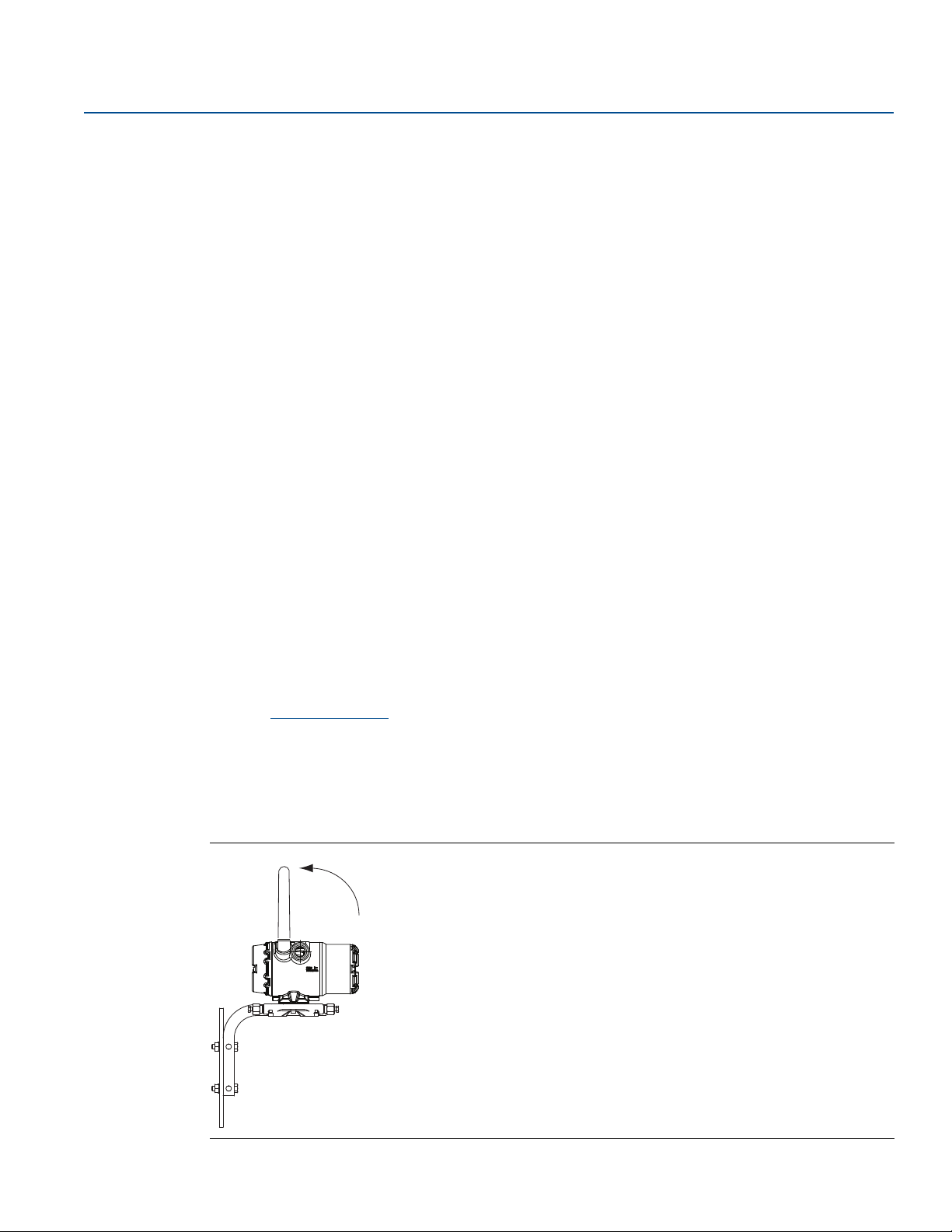
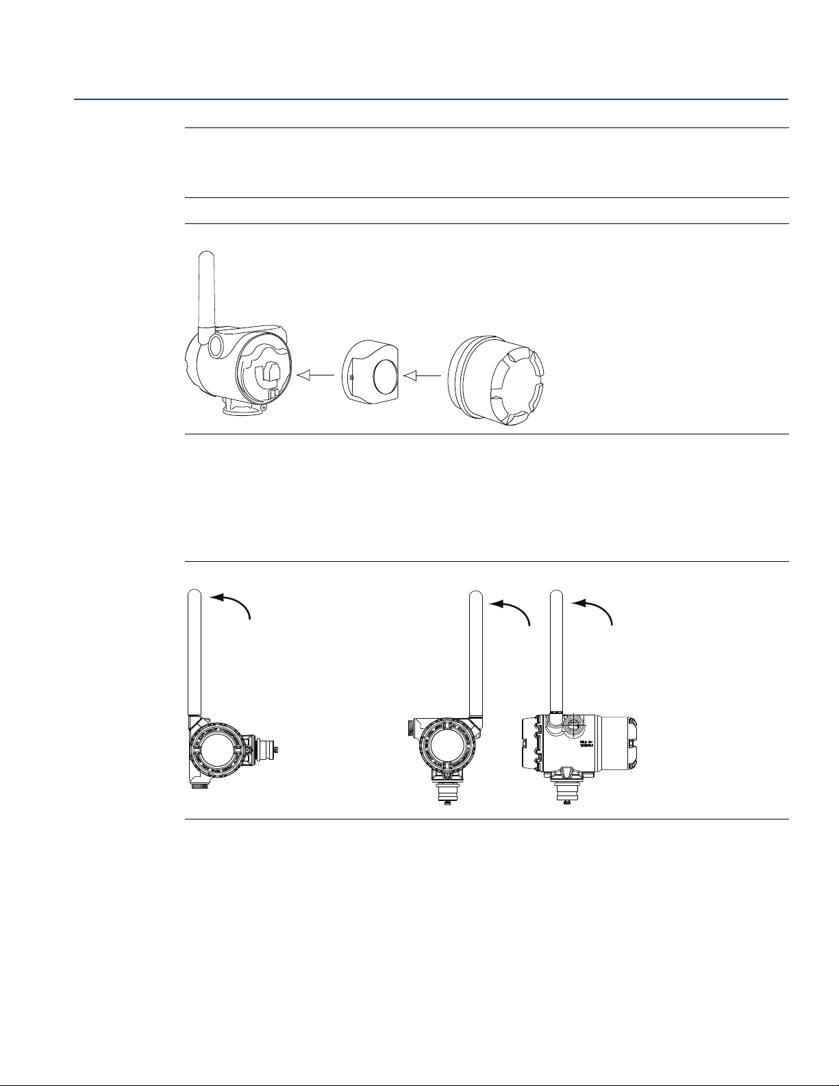
Antenna position
The antenna should be positioned vertically, either straight up or straight down, and it should be
approximately 3 ft. (1 m) from any large structure, building, or conductive surface to allow for clear
communication to other devices.
Figure 1-1. Antenna Position
.
™
Solutions model number 701PBKKF
Introduction
3
Page 12
Introduction
A
A
COMM
P/N 00753-9200-0020
1
2
3
4
June 2018
Reference Manual
00809-0200-4702, Rev EA
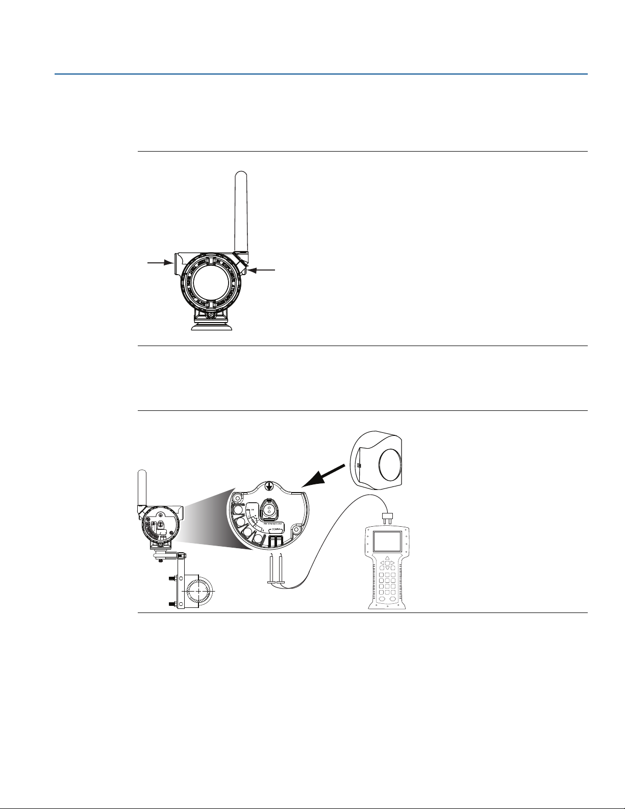
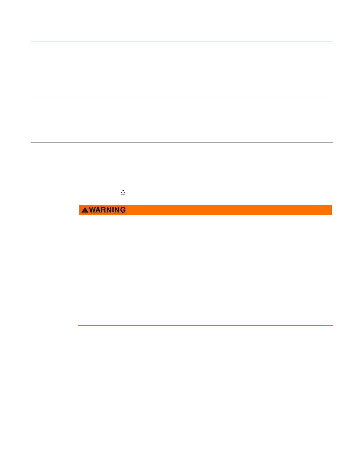
Preparing (or sealing) the conduit entries
Upon installation, ensure that each conduit entry is either sealed with a conduit plug with appropriate
thread sealant, or has an installed conduit fitting or cable gland with appropriate thread sealant.
Figure 1-2. Locating Conduit Entries
A. Conduit entry
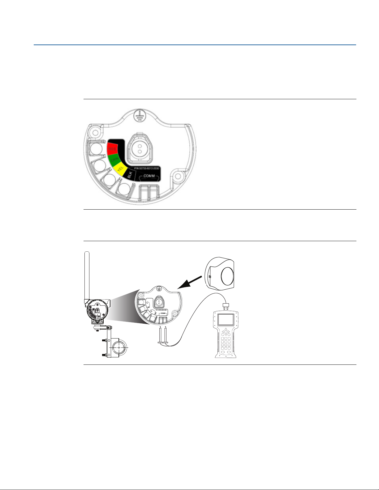
Connecting the Field Communicator to the power module
The power module needs to be connected for the Field Communicator to interface with the transmitter.
Figure 1-3. Field Communicator Connections
1.3.3 Choosing an installation location and position
When choosing an installation location and position, take into account access to the Rosemount 702
Transmitter. For best performance, the antenna should be vertical with space between objects in a
parallel metal plane, such as a pipe or metal framework, as the pipes or framework may adversely affect
the antenna’s performance.
4
Introduction
Page 13
Reference Manual
Housing temperature rise, above ambient
°C (°F)
3 4 5 6 7 8 9
0
60 (108)
50 (90)
40 (72)
30 (54)
20 (36)
10 (18)
4.2
55
Extension length (in.)
815 °C (1500 °F) Process temperature
540 °C (1000 °F) Process temperature
250 °C (482 °F) Process temperature
00809-0200-4702, Rev EA
1.3.4 Electrical
Caring for the power module
The Rosemount 702 Transmitter is self-powered. The included Black Power Module contains two “C” size
primary lithium/thionyl chloride batteries. Each battery contains approximately 2.5 grams of lithium, for
a total of 5 grams in each pack. Under normal conditions, the battery materials are self-contained and
are not reactive as long as the batteries and the power module are maintained. Care should be taken to
prevent thermal, electrical, or mechanical damage. Contacts should be protected to prevent premature
discharge.
Use caution when handling the power module, it may be damaged if dropped from heights in excess of
20 ft. (6,10 m).
Making switch connections
Make switch connections through the cable entry in the side of the connection head. Be sure to provide
adequate clearance for cover removal.
1.3.5 Verifying operating atmosphere
Introduction
June 2018
Verify that the operating atmosphere of the transmitter is consistent with the appropriate hazardous
locations certifications.
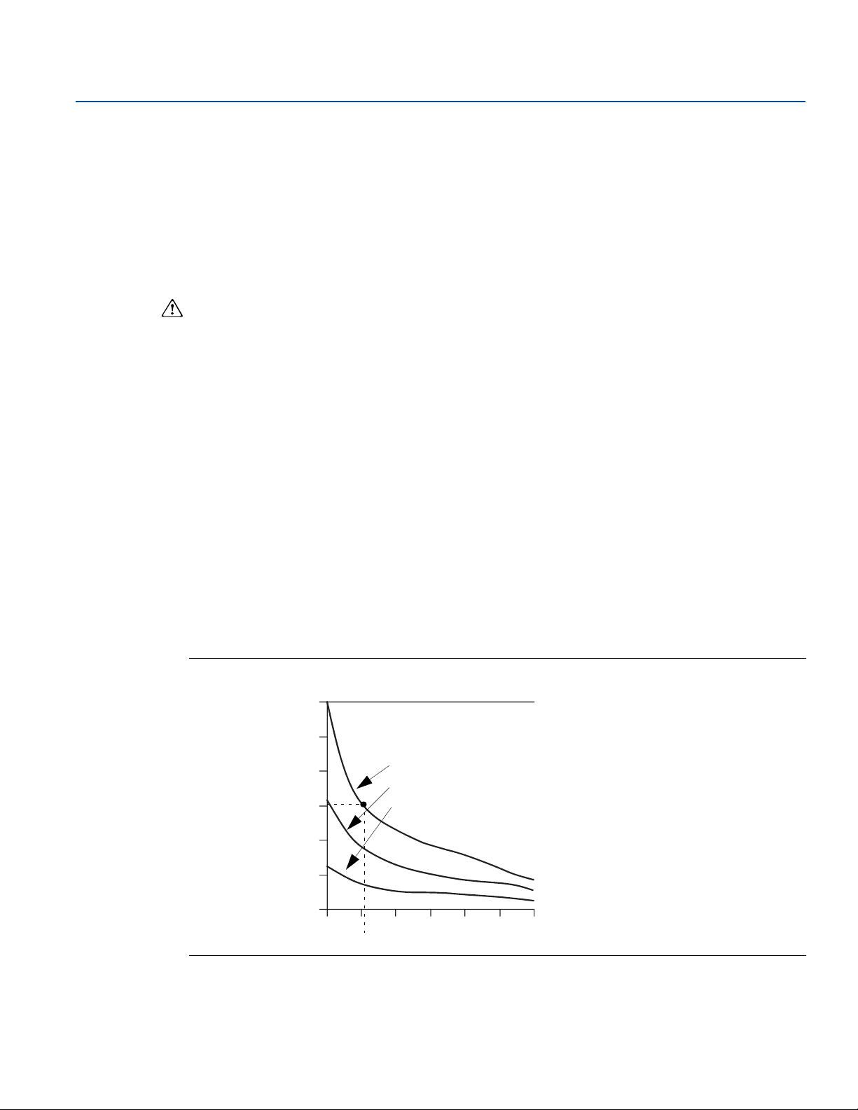
Isolating the transmitter from sources of heat
The transmitter will operate within specifications for ambient temperatures between –40 and 185 °F
(–40 and 85 °C). Heat from the process is transferred from the switch to the transmitter housing. If the
expected process temperature is near or beyond specification limits, consider using an extension, or
remote mount the transmitter to thermally isolate it from the process.
Figure 1-4 provides an example of the relationship between the transmitter housing temperature rise
and the extension length.
Figure 1-4. Rosemount 702 Transmitter Connection Head Temperature Rise vs. Extension Length
Introduction
5
Page 14
Introduction
June 2018
Reference Manual
00809-0200-4702, Rev EA
Example
The transmitter specification limit is 185 °F (85 °C). If the ambient temperature is 131 °F (55 °C) and the
maximum process temperature to be measured is 1500 °F(815 °C), the maximum permissible
connection head temperature rise is the transmitter specification limit minus the ambient temperature
(moves 185 °F to 131 °F [85 to 55 °C]), or 86 °F (30 °C).
In this case, an extension of 5-in. (0.13 m) meets t his requirement, but 6-in. (0.15 m) provides an
additional margin of protection, thereby reducing risk of ambient thermal damage.
Temperature limits
Operating limit Storage limit
With LCD display –40 to 175 °F
–20 to 80 °C
Without LCD display –40 to 185 °F
–40 to 85 °C
1.4 Product recycling/disposal
Recycling of equipment and packaging should be taken into consideration. The product and packaging
should be disposed of in accordance with local and national legislation.
–40 to 185 °F
–40 to 85 °C
–40 to 185 °F
–40 to 85 °C
6
Introduction
Page 15
Reference Manual
00809-0200-4702, Rev EA
Configuration: Models 702DX22 and 702DX61
June 2018
Section 2 Configuration: Models 702DX22
and 702DX61
Safety messages . . . . . . . . . . . . . . . . . . . . . . . . . . . . . . . . . . . . . . . . . . . . . . . . . . . . . . . . . . . . . . . . . . . . . . page 7
Configuring the Device Sensor . . . . . . . . . . . . . . . . . . . . . . . . . . . . . . . . . . . . . . . . . . . . . . . . . . . . . . . . . page 8
Configuring the device network . . . . . . . . . . . . . . . . . . . . . . . . . . . . . . . . . . . . . . . . . . . . . . . . . . . . . . . . page 9
HART menu tree . . . . . . . . . . . . . . . . . . . . . . . . . . . . . . . . . . . . . . . . . . . . . . . . . . . . . . . . . . . . . . . . . . . . . . page 11
Remove power module . . . . . . . . . . . . . . . . . . . . . . . . . . . . . . . . . . . . . . . . . . . . . . . . . . . . . . . . . . . . . . . . page 13
2.1 Safety messages
Instructions and procedures in this section may require special precautions to ensure the safety of the
personnel performing the operations. Information that potentially raises safety issues is indicated by a
warning symbol ( ). Refer to the following safety messages before performing an operation preceded
by this symbol.
Failure to follow these installation guidelines could result in death or serious injury.
Only qualified personnel should perform the installation.
Explosions could result in death or serious injury.
Before connecting a Field Communicator in an explosive atmosphere, make sure that the
instruments are installed in accordance with intrinsically safe or non-incendive field wiring practices.
Verify that the operating atmosphere of the transmitter is consistent with the appropriate hazardous
locations certifications.
Process leaks could result in death or serious injury.
Do not remove the switch while in operation.
Install and tighten switches before applying pressure.
Electrical shock could cause death or serious injury.
Use extreme caution when making contact with the leads and terminals
2.1.1 Connecting the switches
The Rosemount™ 702 Wireless Discrete Transmitter is compatible with a number of simple switches.
When ordered in the optional configuration for Liquid Hydrocarbon Detection, option code 61, the
transmitter is compatible with Tyco
on page 9 shows the correct input connections to the switch terminals on the transmitter. To ensure a
proper switch connection, anchor the switch lead wires into the appropriate compression terminals and
tighten the screws.
®
TraceTek® Fast Fuel Sensors and TraceTek Sensing cable. Figure 2-1
Configuration: Models 702DX22 and 702DX61
7
Page 16

Configuration: Models 702DX22 and 702DX61
June 2018
Wiring the transmitter
If the switch is installed in a high-voltage environment and a fault condition or installation error occurs,
the sensor leads and transmitter terminals could carry lethal voltage. Use extreme caution when making
contact with the leads and terminals.
Use the following steps to wire the sensor and power supply to the transmitter:
1. Remove the transmitter enclosure cover (if applicable).
2. Attach the sensor leads according to the wiring diagram Figure 2-2 on page 10.
3. Connect the Black Power Module.
4. Verify the connection by viewing the LCD.
5. Replace the cover and tighten (if applicable).
2.2 Configuring the Device Sensor
Remove the power module-side housing cover to expose the terminal block and HART® Communication
terminals, then connect the power module to power the unit for configuration. The Rosemount 702
Transmitter will receive any HART Communication from a Field Communicator, or AMS Wireless
Configurator.
Reference Manual
00809-0200-4702, Rev EA
2.3 Configuring on the bench
Field Communicator
When using a Field Communicator, any configuration changes must be sent to the transmitter using the
Send key (F2). AMS Wireless Configurator configuration changes are implemented when the Apply
button is clicked.
AMS Wireless Configurator
AMS Wireless Configurator is capable of connecting to devices directly, using a HART modem, or with
the Gateway. When configuring on the bench with a HART modem, double click the device icon, then
select the Configure/Setup tab (or right click and select Configure/Setup). Configure the device settings
using the Direct Connection menu. When configuring with the Gateway, double click the device icon
then select the Configure/Setup tab (or right click and select Configure/Setup). Configure the device
settings using the Wireless Connection menu. To check or change sensor configuration using a Field
Communicator, enter the following Fast Key Sequence: 2, 2, 2.
8
Configuration: Models 702DX22 and 702DX61
Page 17
Reference Manual
00809-0200-4702, Rev EA
Configuration: Models 702DX22 and 702DX61
2.4 Configuring the device network
Field Communicator
To communicate with the Gateway, and ultimately the information system, the transmitter must be
configured to communicate with the wireless network.
Using a Field Communicator or AMS Wireless Configurator, enter the Network ID and Join Key so they
match the Network ID and Join Key of the Gateway and the other devices in the network. If the Network
ID and Join Key are not identical, the transmitter will not communicate with the network. The Network
ID and Join Key may be obtained from the Gateway on the Setup>Network>Settings page on the web
server. Using a Field Communicator, the Network ID can be configured by entering the Fast Key
Sequence: 2, 2, 1, 1. The Join Key can also be configured using a Field Communicator with the Fast Key
Sequence: 2, 2, 1, 2.
AMS Wireless Configurator
The final device network configuration piece is the Update Rate which, by default, is 1 minute. It can be
changed at commissioning, or at any time, by using AMS Wireless Configurator or the Gateway’s web
server. The update rate should be between 4 seconds and 60 minutes. To change the Update Rate with a
Field Communicator, use the Fast Key Sequence: 2, 2, 1, 3.
June 2018
If doing a bench top initial configuration, after completion remove the power module until installation.
When the device is installed, insert he power module and close the housing cover securely. Always
ensure a proper seal so that metal touches metal, but do not overtighten.
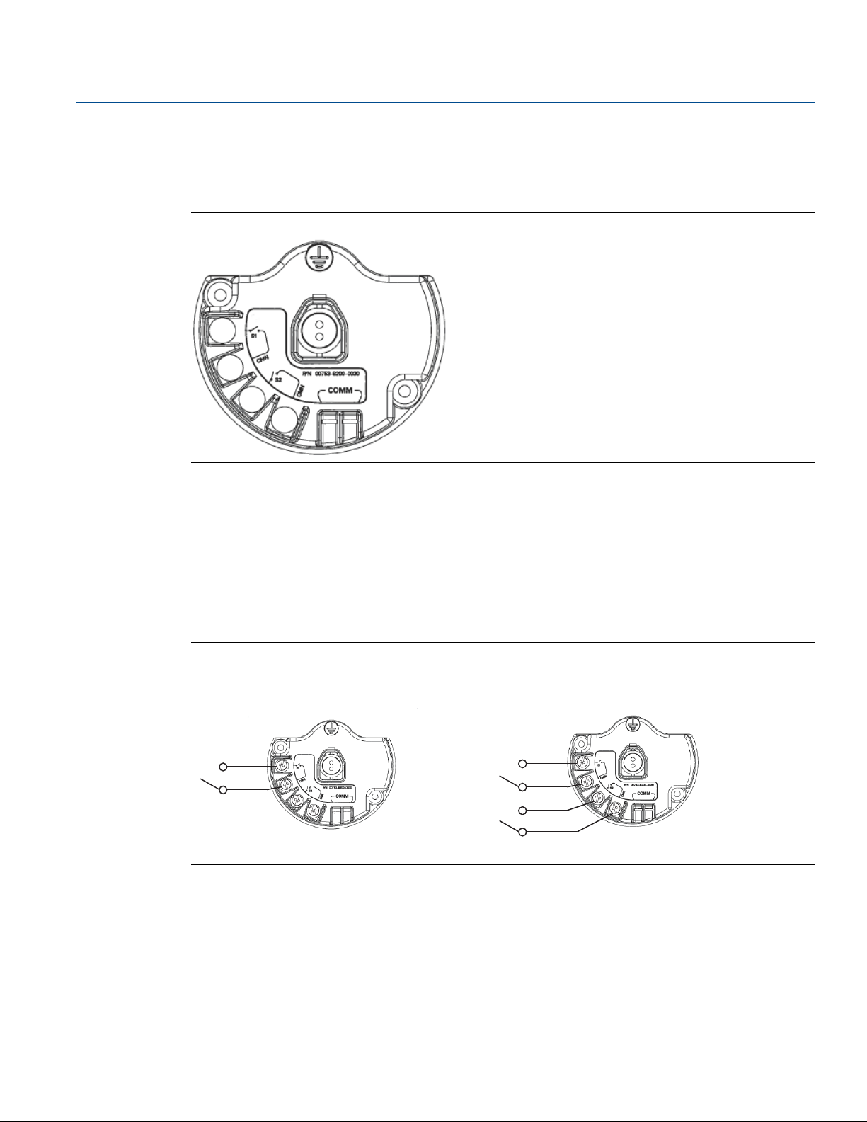
2.4.1 Configuring transmitter with dry contact inputs, measurement
option code 22 (702DX22)
Figure 2-1. Terminal Block
Connect the HART Communication leads to the COMM terminals on the terminal block.
Configuration: Models 702DX22 and 702DX61
9
Page 18
Configuration: Models 702DX22 and 702DX61
COMM
P/N 00753-9200-0020
1
2
3
4
June 2018
Reference Manual
00809-0200-4702, Rev EA
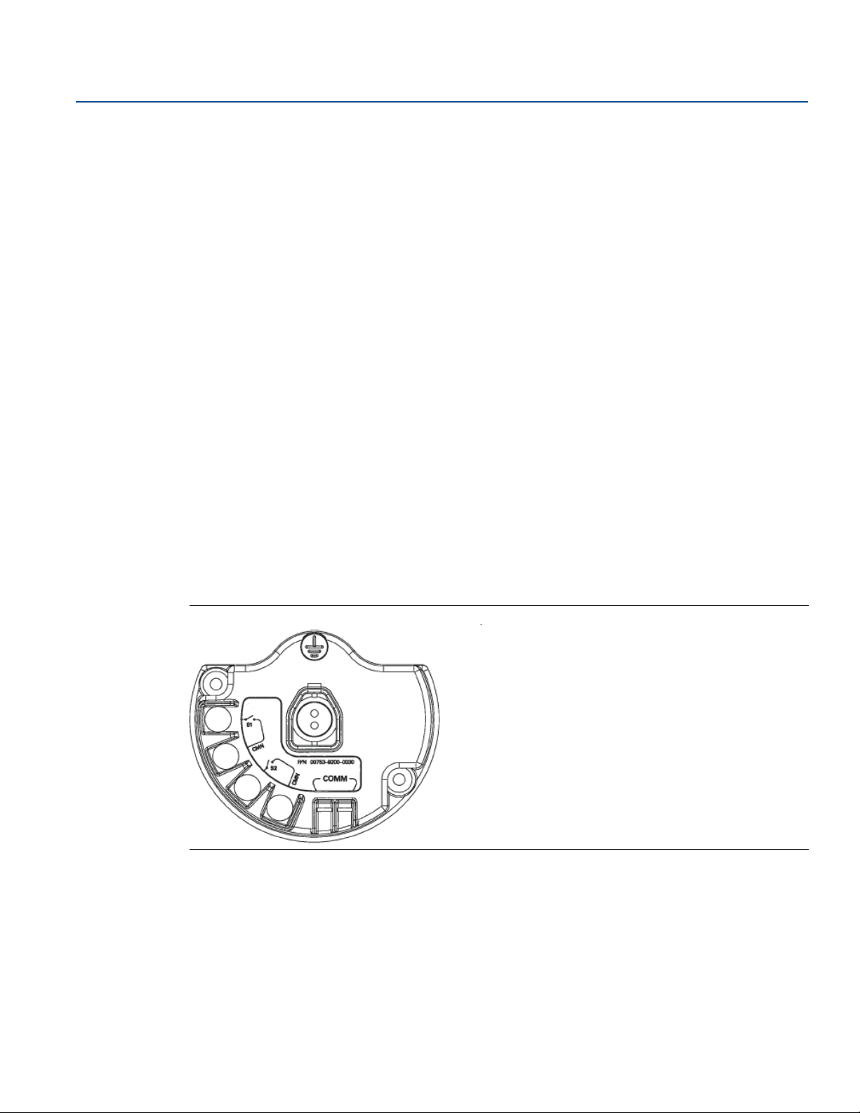
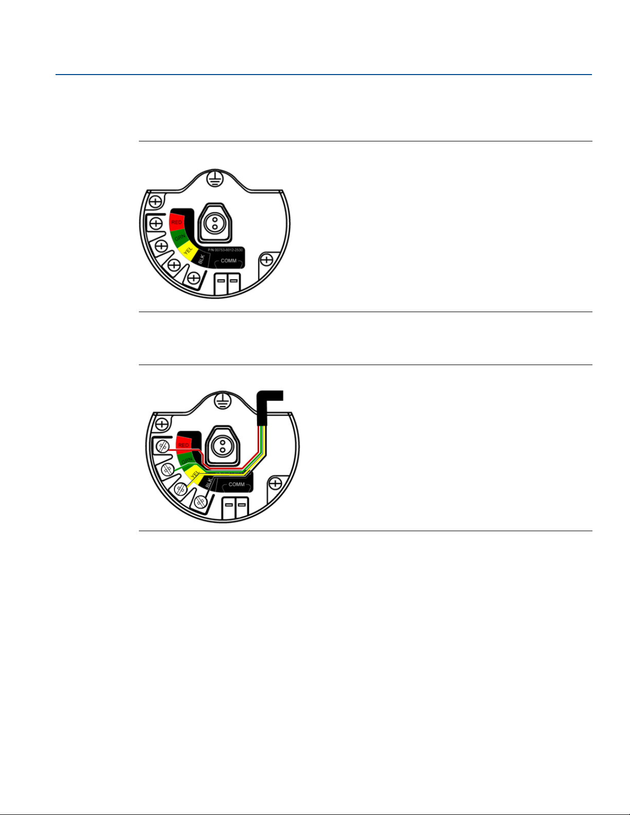
2.4.2 Configuring transmitter with liquid hydrocarbon detection,
measurement option code 61(702DX61)
Making terminal block connections
Figure 2-2. Fuel Sensor Terminal Diagram
Connect Tyco TraceTek and Fast Fuel sensor lead wires by matching the colors of wires to colors on
terminal block.
Figure 2-3. Field Communicator Connections
For HART Communication, a Rosemount 702 DD is required.
10
Configuration: Models 702DX22 and 702DX61
Page 19
Reference Manual
1. Overview
2. Configure
3. Service Tools
1. Active Alerts
2. Communication Status
3. Discrete Input 1
4. Discrete 1 Status
5. Discrete Input 2
6. Discrete 2 Status
7. Last Update Time
8. DD Version
1. Guided Setup
2. Manual Setup
1. Alerts
2. Variables
3. Communications
4. Maintenance
5. Simulate
1. Join Device to Network
2. Configure Update Rate
3. Configure Discrete Application
4. Configure Device Display
1. Wireless
2. Discrete Sensors
3. Electronics Temperature
4. Device Information
5. Device Display
6. Other
1. Active Alerts
2. History
1. Discrete Input 1
2. Discrete 1 Status
3. Discrete Input 2
4. Discrete 2 Status
5. Electronics Temperature
6. Electronics Temperature Status
7. Supply Voltage
8. Supply Voltage Status
9. Last Update Time
1. Join Status
2. Communication Status
3. Join Mode
4. Number of Available Neighbors
5. Number of Advertisements Heard
6. Number of Join Attempts
1. Sensor Calibration
2. Other
1. Discrete 1
2. Discrete 2
3. Ambient Temperature
4. Supply Voltage
1. Clear Alert History
1. Discrete Input 1 Sensor Wiring Offset
2. Discrete Input 2 Sensor Wiring Offset
1. Perform Master Reset
2. Measurement History
3. Advertise to New Devices
4. Install New Power Module
1. Network ID
2. Join Device to Network
3. Broadcast Rates
4. Power Mode
5. Power Source
1. Configure Discrete Application
2. Discrete Input 1
3. Discrete Input 2
1. Electronics Temperature
2. Electronics Temperature Status
3. Unit
4. Maximum
5. Minimum
1. Tag
2. Long Tag
3. Device
4. Discrete Input 1
5. Discrete Input 2
6. Wireless
7. Write Protect
8. Poll Address
1. Mode
1. Write Protect
2. AC Power Filter
3. Measurement and Status Log
1. Configure Update Rate
2. Message 1
3. Message 2
4. Message 3
1. Discrete State
2. Invert Option
3. Sensor Serial Number
1. Discrete State
2. Invert Option
3. Sensor Serial Number
1. Manufacturer
2. Model
3. Final Assembly Number
4. Universal
5. Field Device
6. Software
7. Hardware
8. Descriptor
9. Message
10 Date
11 Model Number I
12 Model Number II
13 Model Number III
14 SI Unit Restriction
15 Country
16 Device ID
1. Sensor Serial Number
1. Sensor Serial Number
1. Manufacturer
2. Device Type
3. Device Revision
4. Software Revision
5. Hardware Revision
Configuration: Models 702DX22 and 702DX61
00809-0200-4702, Rev EA
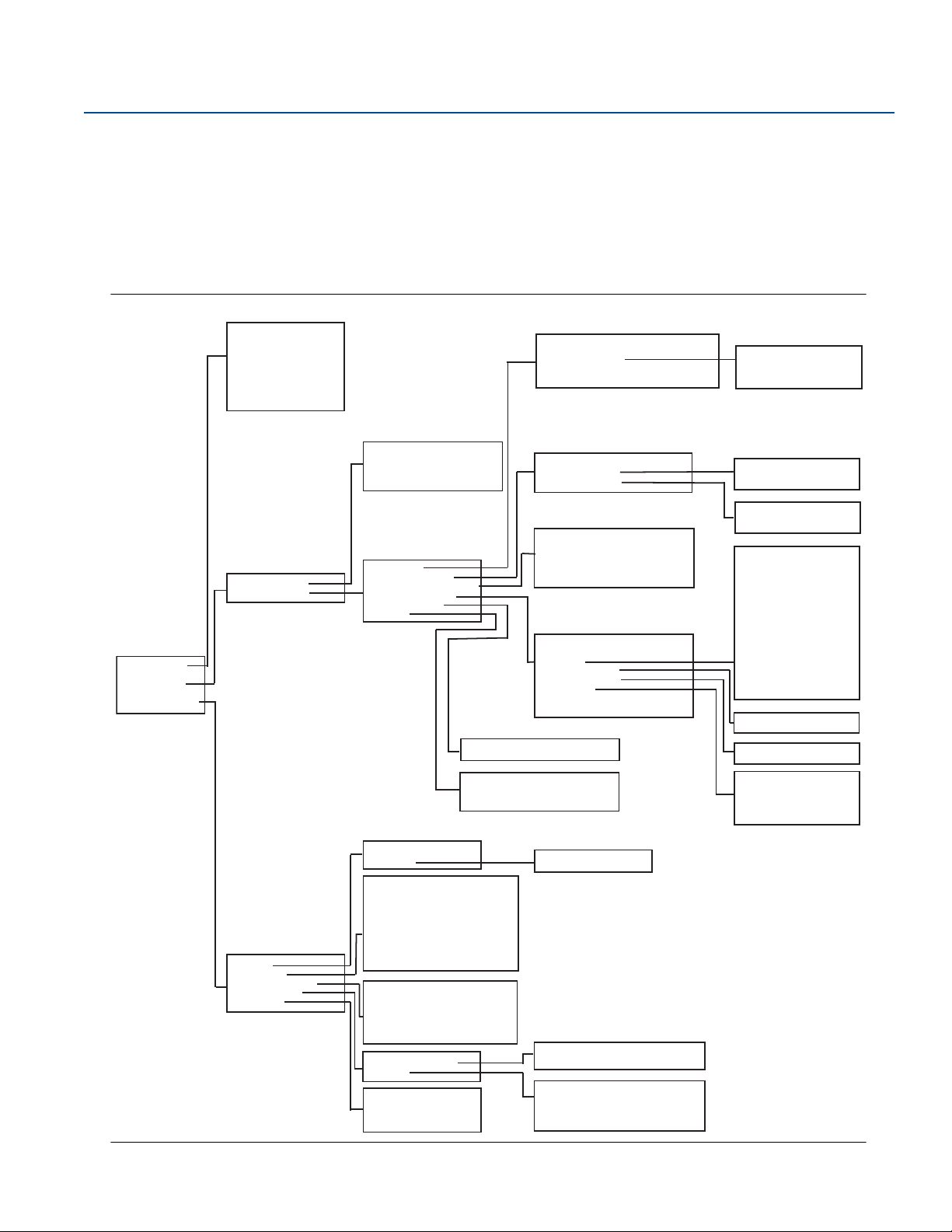
2.5 HART menu tree
For ease of operation, changing setup, such as switch type, can be completed in several
locations.
2.5.1 Dry contact inputs, measurement option code 22
(702DX22)
Figure 2-4. Field Communicator Menu Tree, DD Revision 2
June 2018
Configuration: Models 702DX22 and 702DX61
11
Page 20
Configuration: Models 702DX22 and 702DX61
June 2018
Reference Manual
00809-0200-4702, Rev EA
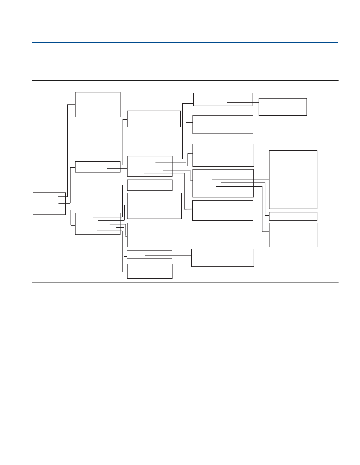
2.5.2 Liquid hydrocarbon detection, measurement option code
61(702DX61)
Figure 2-5. Field Communicator Menu Tree, DD Revision 1, for Leak Detection
1. Overview
2. Configure
3. Service Tools
1. Device Status
2. Communication Status
3. Sensor State
4. Sensor Status
5. Update Rate
6. DD Revision
1. Guided Setup
2. Manual Setup
1. Alerts
2. Variables
3. Communications
4. Routine Maintenance
5. Simulate
1. Join Device to Network
2. Configure Update Rate
3. Configure Sensor
1. Wireless
2. Leak Sensor
3. Electronics Temperature
4. Device Information
5. Other
1. Refresh Alerts
2. History
1. Sensor State
2. Sensor Status
3. Electronics Temperature
4. Electronics temperature Status
5. Supply Voltage
6. Supply Voltage Status
7. Last Update Time
1. Join Status
2. Communication Status
3. Join Mode
4. Number of Available Neighbors
5. Number of Advertisements Heard
6. Number of Join Attempts
1. Other
1. Input
2. Electronics Temperature
3. Supply Voltage
1. Network ID
2. Join Device to Network
3. Broadcast Rates
1. Configure Sensor
2. Sensor State
3. Sensor Status
4. Sensor Serial Number
1. Electronics Temperature
2. Electronics Temperature Status
3. Unit
4. Maximum
5. Minimum
1. Tag
2. Long Tag
3. Device
4. Leak Sensor
5. Wireless
6. Write Protect
7. Polling Address
1. Write Protect
2. AC Power Filter
3. Measurement and Status Log
4. Power Mode
5. Power Source
1. Perform Master Reset
2. Measurement History
3. Advertise to New Devices
4. Install New Power Module
1. Configure Update Rate
2. Message 1
3. Message 2
4. Message 3
1. Manufacturer
2. Model
3. Final Assembly Number
4. Universal
5. Field Device
6. Software
7. Hardware
8. Descriptor
9. Message
10 Date
11 Model Number I
12 Model Number II
13 Model Number III
14 SI Unit Restriction
15 Country
16 Device ID
1. Sensor Serial Number
1. Manufacturer
2. Device Type
3. Device Revision
4. Software Revision
5. Hardware Revision
6. Transmit Power Level
12
Configuration: Models 702DX22 and 702DX61
Page 21
Reference Manual
00809-0200-4702, Rev EA
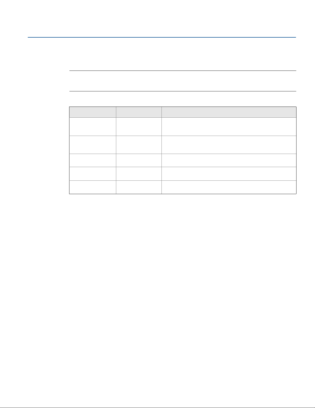
2.5.3 Fast Key sequence
Ta bl e lists the Fast Key sequence for common transmitter functions.
Note
The Fast Key sequences assume that a current DD is being used: DD Rev 2 for dry contact inputs, and DD
Rev 1 for leak detection.
Table 2-1. Rosemount 702 Fast Key sequence
Function Key sequence Menu items
Configuration: Models 702DX22 and 702DX61
June 2018
Device Information 2, 2, 4
Guided Setup 2, 1
Manual Setup 2, 2
Wireless 2, 2, 1
Discrete Input
Configuration
2, 2, 2 Discrete Input Configuration
2.6 Remove power module
After the sensor and network have been configured, remove the power module and replace the
transmitter cover. The power module should be inserted only when the device is ready for
commissioning.
Manufacturer, Model, Final Assembly Number, Universal, Field
Device, Software, Hardware Descriptor, Message, Date, Model
Number, I, II, III, SI Unit Restriction, Country
Join Device to Network, Configure Update Rate, Configure
Sensor, Calibrate Sensor, Configure Display, Configure Process
Alarms
Wireless, Process Sensor, Percent of Range, Device Temperature,
Device Information, Device Configure, Other
Network ID, Join Device to Network, Configure Update Rate,
Configure Broadcast Power Level, Power Mode, Power Source
Configuration: Models 702DX22 and 702DX61
13
Page 22

Configuration: Models 702DX22 and 702DX61
June 2018
Reference Manual
00809-0200-4702, Rev EA
14
Configuration: Models 702DX22 and 702DX61
Page 23
Reference Manual
00809-0200-4702, Rev EA
Models 702DX22 and 702DX61
June 2018
Section 3 Mounting, Wiring Switches, and
Sensors: Models 702DX22 and
702DX61
Safety messages . . . . . . . . . . . . . . . . . . . . . . . . . . . . . . . . . . . . . . . . . . . . . . . . . . . . . . . . . . . . . . . . . . . . . . page 15
Installing the transmitter . . . . . . . . . . . . . . . . . . . . . . . . . . . . . . . . . . . . . . . . . . . . . . . . . . . . . . . . . . . . . . page 16
Wiring switches and sensors . . . . . . . . . . . . . . . . . . . . . . . . . . . . . . . . . . . . . . . . . . . . . . . . . . . . . . . . . . . page 19
LCD display . . . . . . . . . . . . . . . . . . . . . . . . . . . . . . . . . . . . . . . . . . . . . . . . . . . . . . . . . . . . . . . . . . . . . . . . . . page 23
Grounding the transmitter . . . . . . . . . . . . . . . . . . . . . . . . . . . . . . . . . . . . . . . . . . . . . . . . . . . . . . . . . . . . . page 24
3.1 Safety messages
Mounting, Wiring Switches, and Sensors:
Instructions and procedures in this section may require special precautions to ensure the safety of the
personnel performing the operations. Information that potentially raises safety issues is indicated by a
warning symbol ( ). Refer to the following safety messages before performing an operation preceded
by this symbol.
Failure to follow these installation guidelines could result in death or serious injury.
Only qualified personnel should perform the installation.
Explosions could result in death or serious injury.
Before connecting a Field Communicator in an explosive atmosphere, make sure that the
instruments are installed in accordance with intrinsically safe or non-incendive field wiring practices.
Verify that the operating atmosphere of the transmitter is consistent with the appropriate hazardous
locations certifications.
Process leaks could result in death or serious injury.
Do not remove the switch while in operation.
Install and tighten switches before applying pressure.
Electrical shock could cause death or serious injury.
Use extreme caution when making contact with the leads and terminals.
This device complies with Part 15 of the FCC Rules. Operation is subject to the following conditions:
This device may not cause harmful interference. This device must accept any interference received,
including interference that may cause undesired operation.
This device must be installed to ensure a minimum antenna separation distance of 20 cm from all
persons.
Mounting, Wiring Switches, and Sensors: Models 702DX22 and 702DX61
15
Page 24

Mounting, Wiring Switches, and Sensors:
Models 702DX22 and 702DX61
June 2018
3.2 Installing the transmitter
The Rosemount ™ 702 Wireless Discrete Transmitter can be installed in one of two configurations:
Direct mount: The switch is connected directly to the transmitter housing’s conduit entry. For
installation instructions see “Direct mount configuration” on page 16.
Remote mount: The switch is mounted separate from the transmitter housing, then connected to the
transmitter via conduit. For installation instructions see “Remote mount configuration” on page 18. Use
Remote mount instructions for the installation of liquid hydrocarbon sensors.
3.2.1 Direct mount configuration
1. Install the switch according to standard installation practices making sure to use thread sealant on all
of the connections.
2. Attach the Rosemount 702 Transmitter housing to the switch by using the pipe fittings threaded into
the conduit entries.
Reference Manual
00809-0200-4702, Rev EA
Note
Direct mount installation should not be employed when using tubing and connectors such as Swagelok
fittings.
3. Attach the switch wiring to the terminals as shown in the wiring diagrams beginning on page 19.
4. If commissioning the device, install the Black Power Module.
Figure 3-1. Direct Mount
B
A
A. Float switch
B. Rosemount 702 Transmitter
®
16
Note
Use caution when handling the power module, it may be damaged if dropped from heights in excess of
20 ft.
Mounting, Wiring Switches, and Sensors: Models 702DX22 and 702DX61
Page 25
Reference Manual
Possible antenna rotation shown.
Antenna rotation allows for best
installation practices in any
configuration.
00809-0200-4702, Rev EA
Mounting, Wiring Switches, and Sensors:
Models 702DX22 and 702DX61
June 2018
Note
Wireless devices should only be powered up after the Emerson
™
Wireless Gateway, in order of proximity
from the Gateway beginning with the closest device. This results in a simpler and faster network
installation.
Figure 3-2. Power Module Installation
5. Close the housing cover and tighten to safety specifications. Always ensure a proper seal by installing
the electronic housing covers so that metal touches metal, but do not overtighten.
6. Position the antenna such that it is vertical, either straight up or straight down, as shown in
Figure 3-3. The antenna should be approximately 3 ft. (1 m) from any large structures or buildings, to
allow clear communication to other devices.
Figure 3-3. Antenna Positioning
Mounting, Wiring Switches, and Sensors: Models 702DX22 and 702DX61
17
Page 26
Mounting, Wiring Switches, and Sensors:
Models 702DX22 and 702DX61
June 2018
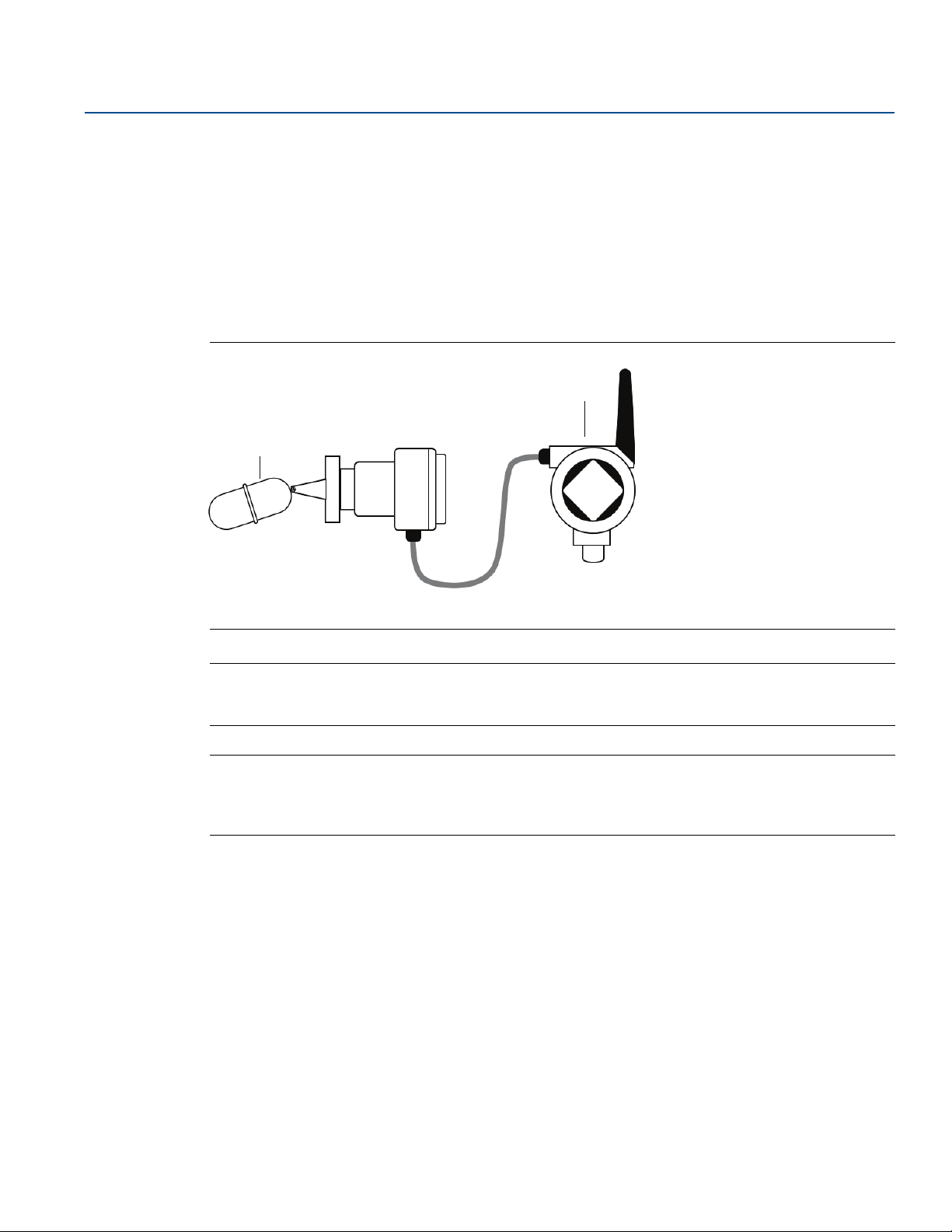
3.2.2 Remote mount configuration
1. Install the switch according to standard installation practices being sure to use thread sealant on all of
the connections.
2. Run wiring (and conduit, if necessary) from the switch to the Rosemount 702 Transmitter.
3. Pull the wiring through the threaded conduit entry.
4. Attach the switch wiring to the terminals as shown in the wiring diagrams beginning on page 19.
5. If commissioning the Transmitter, connect the Power Module as shown in Figure 3-2 on page 17.
Figure 3-4. Remote Mount
A
Reference Manual
00809-0200-4702, Rev EA
B
A. Float switch
B. Rosemount 702 Transmitter
Note
Use caution when handling the power module, it may be damaged if dropped from heights in excess of
20 ft.
Note
Wireless devices should only be powered up after the Emerson Wireless Gateway, in order of proximity
from the Gateway beginning with the closest device. This results in a simpler and faster network
installation.
6. Close the housing cover and tighten to safety specifications. Always ensure a proper seal by installing
the electronic housing covers so that metal touches metal, but do not overtighten.
7. Position the antenna such that it is vertical, either straight up or straight down, as shown in Figure 3-3
on page 17. The antenna should be approximately 3 ft. (1 m) from any large structures or buildings,
to allow clear communication to other devices.
18
Mounting, Wiring Switches, and Sensors: Models 702DX22 and 702DX61
Page 27
Reference Manual
S1
CMN
S2
CMN
00809-0200-4702, Rev EA
Models 702DX22 and 702DX61
June 2018
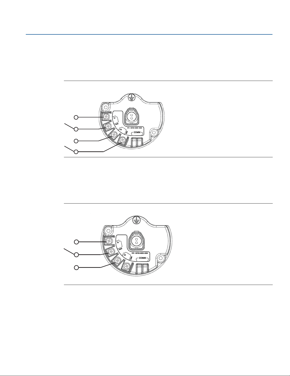
3.3 Wiring switches and sensors
3.3.1 Dry contact inputs, measurement option code 22 (702DX22)
Figure 3-5. Terminal Diagram
Mounting, Wiring Switches, and Sensors:
3.3.2 Wireless output specifications
Dual input
The Rosemount 702 Transmitter will accept the input from one or two single pole single throw switches
on inputs S1 and S2. The wireless output of the transmitter will be both a primary variable (PV) and a
secondary variable (SV). The PV is determined by the S1 input. The SV is determined by the S2 input. A
closed switch drives a TRUE output. An open switch drives a FALSE output.
Figure 3-6. Single and Dual Input
Single input Dual input
Mounting, Wiring Switches, and Sensors: Models 702DX22 and 702DX61
19
Page 28
Mounting, Wiring Switches, and Sensors:
S1
CMN
S2
CMN
S1
CMN
S2
CMN
Models 702DX22 and 702DX61
June 2018
Dual input, limit contact logic
When configured for Limit contact logic, the Rosemount 702 Transmitter will accept the input from two
single pole single throw switches on inputs S1 and S2, and will use limit contact logic for the
determination of the wireless outputs. Reference Figure 3-7 for details on the wireless outputs available
when using limit contact logic.
Figure 3-7. Dual Input, Limit Contacts
Reference Manual
00809-0200-4702, Rev EA
Dual input, opposing contact logic
When configured for opposing contact logic, the Rosemount 702 Transmitter will accept the input from
a single pole double throw switch on inputs S1 and S2, and will use opposing contact logic for the
determination of the wireless outputs. Reference Figure 3-8 for details on the wireless outputs available
when using opposing contact logic.
Figure 3-8. Dual Input, Opposing Contact
20
Mounting, Wiring Switches, and Sensors: Models 702DX22 and 702DX61
Page 29
Reference Manual
00809-0200-4702, Rev EA
Models 702DX22 and 702DX61
3.3.3 Liquid hydrocarbon detection, measurement option code
61(702DX61)
Figure 3-9. Fuel Sensor Terminal
Mounting, Wiring Switches, and Sensors:
June 2018
The liquid hydrocarbon detection configuration is intended for use with the Tyco® Tra ceTek® Fast Fuel
Sensor, or TraceTek Sensing cable.
Figure 3-10. Fuel Sensor Connection
Connecting to the fast fuel sensor and TraceTek sensing cable
The connections to the Fast Fuel Sensor TraceTek Sensing cable are made by matching the appropriately
colored wires to the matching colored termination lugs.
The Rosemount 702 Transmitter can support up to three Tyco Fast Fuel Sensors. These sensors are
connected using TraceTek Modular Leader Cable (TT-MLC-MC-BLK), optional modular jumper cables
(TT-MJC-xx-MC-BLK) and branching connectors (TT-ZBC-MC-BLK) as suggested in Figure 3-11.
If more than one sensor is attached to a transmitter, the detection of liquid hydrocarbon by one sensor
is sufficient to cause the transmitter to send a “Leak” message. However, it is not possible for the
transmitter to discern which individual sensor has detected liquid hydrocarbon.
Mounting, Wiring Switches, and Sensors: Models 702DX22 and 702DX61
21
Page 30
Mounting, Wiring Switches, and Sensors:
A
A
B
B
C
D
Models 702DX22 and 702DX61
June 2018
Figure 3-11. Fuel Sensor Wiring
Reference Manual
00809-0200-4702, Rev EA
A. T-MLC-MC-BLK (leader cable)
B. TT-FFS-100 or TT-FFS-250 (Fast Fuel Sensor probe)
C. TT-MJC-xx-MC-BLK (optional jumper cable)
D. TT-ZBC-xx-MC-BLK (branch connector)
Note
All part numbers on this page refer to products sold by Tyco Thermo Controls, LLC.
The Rosemount 702 Transmitter can support up to 500 ft. (150 m) of TraceTek hydrocarbon or solvent
sensor cable (TT5000 or TT5001 series). The total amount of sensor cable connected to a single
transmitter is not to exceed 500 ft. However leader cable, jumper cables (if used) and branch
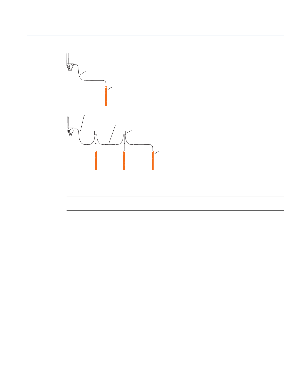
connectors are not included in the 500 ft. limit. See Figure 3-12 for typical configurations.
22
Mounting, Wiring Switches, and Sensors: Models 702DX22 and 702DX61
Page 31

Reference Manual
00809-0200-4702, Rev EA
Figure 3-12. Fuel Sensor Cable Wiring
Mounting, Wiring Switches, and Sensors:
Models 702DX22 and 702DX61
June 2018
A
B
C
C
A. TT-MLC-MC-BLK (leader cable)
B. TT5000/TT5001 Sensor cable (up to 500 ft.)
C. TT-MET-MC (end termination)
D.
TT-MJC-xx-MC-BLK (optional jumper cable)
E. Up to 500 ft. TT5000 or TT5001 sensor cable (total per transmitter)
F. TT-ZBC-xx-MC-BLK (branch connector)
3.4 LCD display
If an LCD display is ordered, it will be shipped attached to the transmitter.
Note
An LCD display is not available with measurement option code 61, for liquid hydrocarbon detection.
D
F
C
E
The optional LCD display can be rotated in 90-degree increments by squeezing the two tabs, pulling out,
rotating and snapping back into place.
If the LCD pins are inadvertently removed from the interface board, carefully re-insert the pins before
snapping the LCD display back into place.
Mounting, Wiring Switches, and Sensors: Models 702DX22 and 702DX61
23
Page 32

Mounting, Wiring Switches, and Sensors:
Models 702DX22 and 702DX61
June 2018
Installing the LCD display
To install the LCD display, use Figure 3-13 on page 24 and the following instructions:
1. Remove the LCD cover. Do not remove the instrument cover in explosive environments when the
circuit is live.
2. Put the four-pin connector into the LCD display, rotate to the desired position and snap into place.
Note the following LCD temperature limits:
Operating: –4 to 175 °F (–20 to 80 °C)
Storage: –40 to 185 °F (–40 to 85 °C)
3. Replace the transmitter cover.
Note
Only use Rosemount Wireless LCD part number: 00753-9004-0002.
Figure 3-13. Optional LCD Display
Reference Manual
00809-0200-4702, Rev EA
AB C
A. LCD pins
B. LCD display
C. LCD cover
3.5 Grounding the transmitter
The Rosemount 702 Transmitter operates with the housing grounded or floating. Floating systems,
however, can cause extra noise that may affect many types of readout devices. If the signal appears noisy
or erratic, grounding at a single point may solve the problem. Grounding of the electronics enclosure
should be done in accordance with local and national installation codes. Grounding is accomplished
through the process connection using the internal or external case grounding terminal.
Determining grounding requirements
24
Each process installation has different grounding requirements. Use the options recommended by the
facility for the specific switch type, or begin with Option 1, which is the most common.
Mounting, Wiring Switches, and Sensors: Models 702DX22 and 702DX61
Page 33

Reference Manual
A
B
C
A
B
C
00809-0200-4702, Rev EA
Option 1:
1. Connect switch wiring shield to the grounded transmitter housing.
2. Ensure that the transmitter housing is electrically isolated from the switch wiring.
A. Float switch
B. Shield ground point
C. Rosemount 702 Transmitter
Option 2:
1. Ground switch wiring shield at the switch.
Mounting, Wiring Switches, and Sensors:
Models 702DX22 and 702DX61
June 2018
2. Ensure that the switch wiring and shield are electronically isolated from the transmitter housing.
A. Float switch
B. Shield ground point
C. Rosemount 702 Transmitter
Note
Always use facility recommended wiring practices.
Mounting, Wiring Switches, and Sensors: Models 702DX22 and 702DX61
25
Page 34

Mounting, Wiring Switches, and Sensors:
Models 702DX22 and 702DX61
June 2018
Reference Manual
00809-0200-4702, Rev EA
26
Mounting, Wiring Switches, and Sensors: Models 702DX22 and 702DX61
Page 35

Reference Manual
00809-0200-4702, Rev EA
Commissioning: Models 702DX22 and 702DX61
June 2018
Section 4 Commissioning: Models 702DX22
and 702DX61
Safety messages . . . . . . . . . . . . . . . . . . . . . . . . . . . . . . . . . . . . . . . . . . . . . . . . . . . . . . . . . . . . . . . . . . . . . . page 27
Configuring the transmitter to communicate with the wireless network . . . . . . . . . . . . . . . . . . . . . page 28
AMS Wireless Configurator . . . . . . . . . . . . . . . . . . . . . . . . . . . . . . . . . . . . . . . . . . . . . . . . . . . . . . . . . . . . . page 28
Field Communicator . . . . . . . . . . . . . . . . . . . . . . . . . . . . . . . . . . . . . . . . . . . . . . . . . . . . . . . . . . . . . . . . . . page 28
Verifying operation . . . . . . . . . . . . . . . . . . . . . . . . . . . . . . . . . . . . . . . . . . . . . . . . . . . . . . . . . . . . . . . . . . .page 29
4.1 Safety messages
Instructions and procedures in this section may require special precautions to ensure the safety of the
personnel performing the operations. Information that potentially raises safety issues is indicated by a
warning symbol ( ). Refer to the following safety messages before performing an operation preceded
by this symbol.
Failure to follow these installation guidelines could result in death or serious injury.
Make sure only qualified personnel perform the installation.
Explosions could result in death or serious injury.
Before connecting a Field Communicator in an explosive atmosphere, make sure the instruments are
installed in accordance with intrinsically safe or non-incendive field wiring practices.
Verify that the operating atmosphere of the transmitter is consistent with the appropriate hazardous
locations certifications.
Process leaks could result in death or serious injury.
Do not remove the switch while in operation.
Install and tighten sensors before applying pressure.
Electrical shock could cause death or serious injury.
Use extreme caution when making contact with the leads and terminals.
Note
The Rosemount
after the Gateway has been installed and is functioning properly.
Wireless devices should be powered up in order of proximity from the gateway, beginning with the
device closest to the Emerson
installation.
™
702 Wireless Discrete Transmitter and all other wireless devices should be installed only
™
Wireless Gateway. This will result in a simpler and faster network
Commissioning: Models 702DX22 and 702DX61
27
Page 36

Commissioning: Models 702DX22 and 702DX61
June 2018
Reference Manual
00809-0200-4702, Rev EA
4.2 Configuring the transmitter to communicate with the wireless network
In order to communicate with the Gateway, and ultimately the Information System, the transmitter
must be configured to communicate with the wireless network. This step is the wireless equivalent of
connecting wires from a transmitter to the information system. Using a Field Communicator or AMS
Wireless Configurator, enter the Network ID and Join Key so that they match the Network ID and Join Key
of the gateway and other devices in the network. If the Network ID and Join Key are not identical, the
Rosemount 702 Transmitter will not communicate with the network. The Network ID and Join Key may
be obtained from the Emerson Wireless Gateway on the Setup>Network>Settings page on the web server,
shown in Figure 4-1.
Figure 4-1. Gateway Network Settings
4.3 AMS Wireless Configurator
Right click on the Rosemount 702 Transmitter and select Configure. When the menu opens, select Join
Device to Network and follow the method to enter the Network ID and Join Key.
4.4 Field Communicator
The Network ID and Join Key may be changed in the wireless device by using the following Fast Key
sequence. Set both Network ID and Join Key.
Func tion Key Sequence Menu Items
Wireless Setup
28
2, 1, 1
Network ID, Set Join Key
Operation and Maintenance
Page 37

Reference Manual
i d - 1 2
3 4 5 6 7 8
n e t w k
13 0 5
I D
S u p l y
7. 2 1
v o l t s
00809-0200-4702, Rev EA
4.5 Verifying operation
There are four ways to verify operation: using the optional local display (LCD), using the Field
Communicator, using the Gateway's integrated web interface, or by using AMS Suite Wireless
Configurator. If the Rosemount 702 Transmitter was configured with the Network ID and Join Key, and
sufficient time has passed, the transmitter will be connected to the network.
Troubleshooting
If the device is not joined to the network after power up, verify the correct configuration of the Network
ID and Join Key, and verify that Active Advertising has been enabled on the Gateway. The Network ID and
Join Key in the device must match the Network ID and Join Key of the Gateway.
Operating the local display
The LCD displays the PV and SV values at the configured update rate, but no faster than once every 60
seconds.
Diagnostic button display sequence
More detailed diagnostic information can be obtained by removing the display cover of the Rosemount
702 Transmitter, and momentarily depressing the “DIAG” button. The LCD will display the diagnostic
screens as shown in Figure 4-3.
Commissioning: Models 702DX22 and 702DX61
June 2018
Press the Diagnostic button to display the TAG, Device ID, Network ID, Network Join Status and Device
Status screens.
Figure 4-2. Diagnostic Screen Sequence
Tag Device ID Network ID
A b c d e
f g h
Network Join
Status
n e t w k
O K
Device
Status
Network join status
The chevron-shaped status bar at the top of the screen indicates the progress of the network join
process. When the status bar is filled, the device is successfully connected to the wireless network. This is
shown, in Figure 4-3 on page 30.
Commissioning: Models 702DX22 and 702DX61
29
Page 38

Commissioning: Models 702DX22 and 702DX61
N E T w K
S R C H N G
n e t w k
N E G O T
n e t w k
O K
June 2018
Figure 4-3. Network Join Status Screens
Reference Manual
00809-0200-4702, Rev EA
Searching for
Network
Joining Network
Connected with
Limited
Bandwidth
n e t w k
L I M - O P
Connected
Connecting with a Field Communicator
A Rosemount 702 DD is required for HART communication. For connecting with a Field Communicator,
refer to Figure 2-3 on page 10.
Func tion Key Sequence Menu Items
Communications 3,3
Join Status, Communication Status, Join Mode, Number of
Available Neighbors, Number of Advertisements Heard,
Number of Join Attempts
Checking for communication using the Gateway
In the integrated web interface from the Gateway, navigate to the Explorer page. This page shows
whether the device has joined the network and if it is communicating properly.
Note
The time to join the new device(s) to the network is dependent upon the number of devices being joined
and the number of devices in the current network. For one device joining an existing network with
multiple devices, it may take up to five minutes. It may take up to 60 minutes for multiple new devices to
join the existing network.
Alarm configuration
if the device joins the network and immediately has an alarm present, it is likely due to sensor
configuration. Check the sensor wiring (see “Terminal Block” on page 9) and the sensor configuration
(see “Fast Key sequence” on page 13).
30
Operation and Maintenance
Page 39

Reference Manual
00809-0200-4702, Rev EA
Figure 4-4. Gateway Explorer Page
Commissioning: Models 702DX22 and 702DX61
June 2018
4.5.1 AMS Wireless Configurator
When the device has joined the network, it will appear in the Device Manager as illustrated below:
Troubleshooting
If the device is not joined to the network after power up, verify the correct configuration of the Network
ID and Join Key, and verify that Active Advertising has been enabled on the Gateway. The Network ID and
Join Key in the device must match the Network ID and Join Key of the Gateway.
The Network ID and Join Key may be obtained from the Gateway on the
Setup>Network>Settings page on the web interface (see Figure 4-4 on page 31). The Network ID and Join
Key may be changed in the wireless device by using the following Fast Key sequence.
Function Key Sequence Menu Items
Wireless 2,1,1 Join Device to Network
Commissioning: Models 702DX22 and 702DX61
31
Page 40

Commissioning: Models 702DX22 and 702DX61
June 2018
Reference Manual
00809-0200-4702, Rev EA
32
Operation and Maintenance
Page 41

Reference Manual
00809-0200-4702, Rev EA
Models 702DX22 and 702DX61
Section 5 Operation and Maintenance:
Models 702DX22 and 702DX61
Safety Messages . . . . . . . . . . . . . . . . . . . . . . . . . . . . . . . . . . . . . . . . . . . . . . . . . . . . . . . . . . . . . . . . . . . . . . page 33
Discrete input from switches and sensors . . . . . . . . . . . . . . . . . . . . . . . . . . . . . . . . . . . . . . . . . . . . . . . .page 34
LCD display screen messages . . . . . . . . . . . . . . . . . . . . . . . . . . . . . . . . . . . . . . . . . . . . . . . . . . . . . . . . . . . page 40
Replacing the power module . . . . . . . . . . . . . . . . . . . . . . . . . . . . . . . . . . . . . . . . . . . . . . . . . . . . . . . . . . . page 48
Service support . . . . . . . . . . . . . . . . . . . . . . . . . . . . . . . . . . . . . . . . . . . . . . . . . . . . . . . . . . . . . . . . . . . . . . . page 49
5.1 Safety Messages
Instructions and procedures in this section may require special precautions to ensure the safety of the
personnel performing the operations. Information that potentially raises safety issues is indicated by a
warning symbol ( ). Refer to the following safety messages before performing an operation preceded
by this symbol.
Operation and Maintenance:
June 2018
Failure to follow these installation guidelines could result in death or serious injury.
Make sure only qualified personnel perform the installation.
Explosions could result in death or serious injury.
Before connecting a Field Communicator in an explosive atmosphere, make sure the instruments
are installed in accordance with intrinsically safe or non-incendive field wiring practices.
Verify that the operating atmosphere of the transmitter is consistent with the appropriate
hazardous locations certifications.
Process leaks could result in death or serious injury.
Do not remove the switch while in operation.
Install and tighten sensors before applying pressure.
Electrical shock could cause death or serious injury.
Use extreme caution when making contact with the leads and terminals.
Operation and Maintenance: Models 702DX22 and 702DX61
33
Page 42

Operation and Maintenance:
S1
CMN
S2
CMN
S1
CMN
S2
CMN
Models 702DX22 and 702DX61
June 2018
Reference Manual
00809-0200-4702, Rev EA
5.2 Discrete input from switches and sensors
5.2.1 Dry contact inputs, measurement option code 22 (702DX22)
.
Figure 5-1. Terminal Diagram
5.2.2 Wireless output specifications
Dual input
The Rosemount™ 702 Wireless Discrete Transmitter will accept the input from one or two single pole
single throw switches on inputs S1 and S2. The wireless output of the transmitter will be both a primary
variable (PV) and a secondary variable (SV). The PV is determined by the S1 input. The SV is determined
by the S2 input. A closed switch drives a TRUE output. An Open switch drives a FALSE output.
34
Note
Any dry contact input can be inverted by the device, so as to give the opposite effect. This is useful, for
instance, if a normally open switch is used to replace a normally closed switch.
Figure 5-2. Single and Dual Input
Single input Dual input
Operation and Maintenance: Models 702DX22 and 702DX61
Page 43

Reference Manual
S1
CMN
S2
CMN
00809-0200-4702, Rev EA
Switch input Wireless output Switch input Wireless output
Closed TRUE (1.0) Closed TRUE (1.0)
Dual input, limit contact logic
When configured for limit contact logic, the Rosemount 702 Transmitter will accept the input from two
single pole single throw switches on inputs S1 and S2, and will use limit contact logic for the
determination of the wireless outputs. The following tables describe the wireless outputs available when
using limit contact logic.
Figure 5-3. Dual Input, Limit Contacts
Operation and Maintenance:
Models 702DX22 and 702DX61
June 2018
S1 PV S2 SV
Open FALSE ( 0.0) Open FALSE (0.0)
Switch inputs Wireless outputs
S1 S2 PV SV
Open Open TRAVEL (0.5) TRAVEL (0.5)
Open Closed FALSE (0.0) FALSE (0. 0)
Closed Open TRUE (1.0) TRUE (1.0)
Closed Closed FAULT (Na N) FAU LT( NaN )
Dual input, opposing contact logic
When configured for Opposing Contact Logic, the Rosemount 702 Transmitter will accept the input from
a single pole double throw switch on inputs S1 and S2, and will use opposing contact logic for the
determination of the wireless outputs. The following tables describe the wireless outputs available when
using opposing contact logic.
Operation and Maintenance: Models 702DX22 and 702DX61
35
Page 44

Operation and Maintenance:
S1
CMN
S2
CMN
Models 702DX22 and 702DX61
June 2018
Figure 5-4. Dual Input, Opposing Contact
Switch inputs Wireless outputs
S1 S2 PV SV
Reference Manual
00809-0200-4702, Rev EA
Open Open FAULT(NaN) FAU LT(N aN)
Open Closed FALS E (0.0) FALSE (0.0)
Closed Open TRUE (1.0) TRUE (1.0)
Closed Closed FAULT(NaN) FAU LT(N aN)
5.2.3 Liquid hydrocarbon detection, measurement option code 61
(702DX61)
Figure 5-5. Fuel Sensor Terminal
36
The Liquid Hydrocarbon Detection configuration is intended for use with the Tyco® TraceTek® Fast Fuel
Sensor, or TraceTek Sensing cable.
Operation and Maintenance: Models 702DX22 and 702DX61
Page 45

Reference Manual
00809-0200-4702, Rev EA
Figure 5-6. Fuel Sensor Connection
Connecting the transmitter to the Fast Fuel Sensor and TraceTek
Sensing Cable
The connections to the Fast Fuel Sensor TraceTek sensing cable are made by matching the appropriately
colored wires to the matching colored termination lugs.
The Rosemount 702 Transmitter can support up to three Fast Fuel Sensors. These sensors are
connected using TraceTek Modular Leader Cable (TT-MLC-MC-BLK), optional modular jumper cables
(TT-MJC-xx-MC-BLK) and branching connectors (TT-ZBC-MC-BLK) as suggested in Figure 3-11 on
page 22.
Operation and Maintenance:
Models 702DX22 and 702DX61
June 2018
Using the AMS Device Manager with the liquid hydrocarbon detection
option
The following figures show how the AMS Device Manager overview screen looks for the Rosemount 702
Transmitter with liquid hydrocarbon detection option, for each of the leak sensor conditions:
Figure 5-7. Normal Status
Operation and Maintenance: Models 702DX22 and 702DX61
37
Page 46

Operation and Maintenance:
Models 702DX22 and 702DX61
June 2018
Figure 5-8. Leak Status
Reference Manual
00809-0200-4702, Rev EA
Figure 5-9. Leak Sensor Not Connected Status
Table 5-1. Liquid Hydrocarbon Detection Interface, for Modbus® mapping
PV SV Description/interpretation
38
1.0 1.0 Normal condition, no leak detected, sensor status good
0.0 1.0 or 0.0 Leak detected, sensor status good
1.0 0.0 Sensor Not Connected, Assume Leak, take appropriate action
Operation and Maintenance: Models 702DX22 and 702DX61
Page 47

Reference Manual
00809-0200-4702, Rev EA
Ta bl e 5 - 1 describes use of the Rosemount 702 Transmitter for hydrocarbon detection in other
communications protocols such as Modbus or OPC. It is imperative that both PV and SV be mapped to
the host system so as to make a good interpretation of the condition and status of the leak detector.
Note
It is imperative that both PV and SV be mapped to the host system so that the diagnostic information on
the sensor status is captured.
In addition, system considerations must be observed to ensure that the device is still connected to the
wireless network and reporting values. On an Emerson Wireless Gateway, this can be done by referring
to the parameter: PV_HEALTHY. PV_HEALTHY has a “True” state when the device is on the network and
its updates are current, not late or stale, and the device is functioning properly. A “False” state of
PV_HEALTHY means that the device is either off of the network, the data updates are not current, or that
there is a malfunction of the device (such as an electronics failure). In the case of a “False” state of
PV_HEALTHY, it is recommended to assume that the device is not connected to the network and to take
appropriate action.
Mapping the PV, SV, and PV_HEALTHY Variables and Parameter
Below is a shot of the Gateway screen where the PV, SV and PV_HEALTHY variables and parameter can be
mapped.
Operation and Maintenance:
Models 702DX22 and 702DX61
June 2018
Figure 5-10. Gateway Modbus Register Map
The Fast Fuel Sensor Diagnostics will propagate via the SV variable. This additional information will
provide additional sensor Status information while using the TraceTek Fast Fuel Sensor.
Warning: If a device becomes not present on the wireless network, Appropriate action must be taken
by the host system.
Important notes regarding the use of Tyco TraceTek Fast Fuel Sensor and TraceTek Sensing cable:
Tyco TraceTek sensors must be installed as per manufacturer recommendations.
Do not run the Rosemount 702 Transmitter for long periods (more than two weeks) with a Tyco fuel
sensor in the leak state as this will more rapidly deplete the power module.
Operation and Maintenance: Models 702DX22 and 702DX61
39
Page 48

Operation and Maintenance:
702
W I r e l s
s n s r1
True
Models 702DX22 and 702DX61
June 2018
5.3 LCD display screen messages
Note
Dry Contact Inputs only, Measurement Option Code 22. LCD is not available for Liquid Hydrocarbon
Detection, Measurement Option Code 61.
5.3.1 Startup screen sequence
The following screens will display when the power module is first connected to the Rosemount 702
Transmitter:
Reference Manual
00809-0200-4702, Rev EA
X X X X X
X X X X x x x
x x x x x x
A b c d e
f g h
1. All Segments On: used to visually determine if there are any
bad segments on the LCD
2. Device Identification: used to determine Device Type.
3. Device Information - Tag: user entered tag which is eight
characters long - will not display if all characters are blank
40
4. PV Screen - Discrete input 1 or logic output value depending
on how the device is configured
Operation and Maintenance: Models 702DX22 and 702DX61
Page 49

Reference Manual
S N S R 2
True
D E V
2 5. 2 5
d e g c
S u p l y
7. 2 1
v o l t s
a l e r t
p r e s n t
00809-0200-4702, Rev EA
Operation and Maintenance:
Models 702DX22 and 702DX61
June 2018
5. SV Screen - Discrete input 2
6. TV Screen - feature board temperature value
7. QV Screen - voltage reading at the power module terminals
8. Alert Screen - at least one alert is present - this screen will not
display if no alerts are present
Operation and Maintenance: Models 702DX22 and 702DX61
41
Page 50

Operation and Maintenance:
n e t w k
13 0 5
I D
n e t w k
O K
S u p l y
7. 2 1
v o l t s
Models 702DX22 and 702DX61
June 2018
5.3.2 Diagnostic button screen sequence
The following five screens will display when the device is operating properly and the Diagnostic Button
has been pressed:
Reference Manual
00809-0200-4702, Rev EA
A b c d e
f g h
i d - X X
X X X X X X
1. Device Information - Tag: user entered tag which is eight
characters long - will not display if all characters are blank
2. Device Identification: used to determine Device ID
3. Network ID: assuming the device has the correct join key, this
ID tells the user what network the device can connect with
42
4. Network Connection Status: the device has joined a network
and has been fully configured and has multiple parents
5. Supply Voltage: voltage reading at the power module
terminals
Operation and Maintenance: Models 702DX22 and 702DX61
Page 51

Reference Manual
n e t w k
u n k n w n
n e t w k
I N I T
n e t w k
i d l e
N E T w K
S R C H N G
00809-0200-4702, Rev EA
5.3.3 Network connection status screens
These screens display the network status of the device. Only one will be shown in the fourth position of
the diagnostic button screen sequence.
1. Diagnostic Button Screen 4.1: the device is attempting to start
the radio
Operation and Maintenance:
Models 702DX22 and 702DX61
June 2018
n e t w k
D I S C N T
2. Diagnostic Button Screen 4.2: the device has just restarted
3. Diagnostic Button Screen 4.3: the device is starting to join the
process
4. Diagnostic Button Screen 4.4: the device is in a disconnected
state and requires a “Force Join” command to join the network
Operation and Maintenance: Models 702DX22 and 702DX61
5. Diagnostic Button Screen 4.5: the device is searching for the
Network
43
Page 52

Operation and Maintenance:
n e t w k
N E G O T
n e t w k
L I M - O P
n e t w k
O K
Models 702DX22 and 702DX61
June 2018
Reference Manual
00809-0200-4702, Rev EA
6. Diagnostic Button Screen 4.6: the device is attempting to join a
network
n e t w k
c o n e c t
7. Diagnostic Button Screen 4.7: the device is connected to the
Network, but is in a “Quarantined” state
8. Diagnostic Button Screen 4.8: the device is joined and
operational, but is running with limited bandwidth for sending
periodic data
9. Diagnostic Button Screen 4.9: the device has joined a network
and has been fully configured and has multiple parents
44
Operation and Maintenance: Models 702DX22 and 702DX61
Page 53

Reference Manual
S N S R 2
True
D E V
2 5. 2 5
d e g c
00809-0200-4702, Rev EA
5.3.4 Device diagnostic screens
The following screens will show the device diagnostics depending on the state of the device and will
appear after screen 5 of the Diagnostic Button Screen Sequence.
Operation and Maintenance:
Models 702DX22 and 702DX61
June 2018
D E V
f A i l u r
s n s r1
True
1. Device Information - Status: there is a critical error which may
prevent the device from operating correctly. Check additional
status screens for more information.
2. PV Screen - Discrete input 1 or logic output value depending on
how the device is configured
3. SV Screen - Discrete input 2
Operation and Maintenance: Models 702DX22 and 702DX61
4. TV Screen - feature board temperature value
45
Page 54

Operation and Maintenance:
S u p l y
7. 2 1
v o l t s
a l e r t
p r e s n t
i d - 1 2
3 4 5 6 7 8
s u p l y
f a i l u r
Models 702DX22 and 702DX61
June 2018
Reference Manual
00809-0200-4702, Rev EA
5. QV Screen - voltage reading at the power supply terminals
6. Alert Screen - at least one alert is present - this screen will not
display if no alerts are present
A b c d e
f g h
7. Diagnostic Button Screen 1 - Tag: user entered tag which is
eight characters long - will not display if all characters are blank
8. Diagnostic Button Screen 2: the device’s
identifier that is used to make up the HART
long address - the Rosemount 1420 Wireless
Gateway may use this to help identify devices
if no unique user tag is available
9. Diagnostic Button Screen 7.1: the terminal
voltage has dropped below level of operating
limit. Replace the power module
(Part Number: 00753-9220-0001)
46
Operation and Maintenance: Models 702DX22 and 702DX61
Page 55

Reference Manual
s u p l y
l o w
r a d i o
f a i l u r
c o n f g
f a i l u r
c o n f g
w a r n
s n s r
f a i l u r
00809-0200-4702, Rev EA
Operation and Maintenance:
Models 702DX22 and 702DX61
June 2018
10. Diagnostic Button Screen 7.2: the terminal voltage is below the
recommended operating range - if this is a self-operated device,
the power module should be replaced - for line powered
devices, the supply voltage should be increased
11. Diagnostic Button Screen 8: the device cannot retrieve
information from the radio in the device - the device may still
be operational and publishing HART data
12. Diagnostic Button Screen 9.1: configuration of the transmitter
is invalid such that critical operation of the device may be
affected - check the extended configuration status to identify
which configuration item(s) need to be corrected
13. Diagnostic Button Screen 9.2: configuration of the transmitter
is invalid such that non-critical operation of the device may be
affected - check the extended configuration status to identify
which configuration item(s) need to be corrected
14. Diagnostic Button Screen 10.1: a switch attached to the
transmitter has failed, and valid readings from that switch are
no longer possible - check the switch and switch wiring
connections - check additional status for more detailed
information of the failure source
Operation and Maintenance: Models 702DX22 and 702DX61
47
Page 56

Operation and Maintenance:
Models 702DX22 and 702DX61
June 2018
Note
Use Rosemount wireless LCD display part number: 00753-9004-0002.
5.4 Replacing the power module
Reference Manual
00809-0200-4702, Rev EA
Expected power module life is ten years at reference conditions.
When the power module needs to be replaced, remove the power module cover and the depleted power
module. Replace the power module with a new Black Power Module, SmartPower
number 701PBKKF (part number 00753-9220-0001). Then replace the cover and tighten it to
specification. Always ensure a proper seal so that metal touches metal, but do not overtighten.
(1)
™
Solutions model
Handling the power podule
The Black Power Module with the wireless unit contains two “C” size primary lithium/thionyl chloride
batteries. Each battery contains approximately 2.5 grams of lithium, for a total of 5 grams in each pack.
Under normal conditions, the battery materials are self-contained and are not reactive as long as the
batteries and the battery pack integrity are maintained. Care should be taken to prevent thermal,
electrical or mechanical damage. Contacts should be protected to prevent premature discharge.
Use caution when handling the power module, it may be damaged if dropped from heights in excess of
20 ft.
Battery hazards remain when cells are discharged.
Environmental considerations
As with any battery, local environmental rules and regulations should be consulted for proper
management of spent batteries. If no specific requirements exist, recycling through a qualified recycler is
encouraged. Consult the materials safety data sheet for battery specific information.
Shipping considerations
The unit was shipped to you without the power module installed. Remove the power module prior to
shipping.
Each power module contains two “C” size primary lithium batteries. Primary lithium batteries are
regulated in transportation by the U.S. Department of Transportation, and are also covered by
International Air Transport Association (IATA), International Civil Aviation Organization (ICAO), and
European Ground Transportation of Dangerous Goods (ARD). It is the responsibility of the shipper to
ensure compliance with these or any other local requirements. Consult current regulations and
requirements before shipping.
1. Reference conditions are 70 °F (21 °C), wireless update of once per minute, and routing data for three additional network devices.
48
Operation and Maintenance: Models 702DX22 and 702DX61
Page 57

Reference Manual
00809-0200-4702, Rev EA
5.5 Service support
To expedite the return process outside of North America, contact your Emerson™
representative,
Within the United States, call the Emerson Response Center toll-free number 1 800 654 7768. The
center, which is available 24 hours a day, will assist you with any needed information or materials.
The center will ask for product model and serial numbers, and will provide a Return Material
Authorization (RMA) number. The center will also ask for the process material to which the product was
last exposed.
Individuals who handle products exposed to a hazardous substance can avoid injury if they are informed
of, and understand, the hazard. If the product being returned was exposed to a hazardous substance as
defined by OSHA, a copy of the required Material Safety Data Sheet (MSDS) for each hazardous
substance identified must be included with the returned goods.
Operation and Maintenance:
Models 702DX22 and 702DX61
June 2018
Operation and Maintenance: Models 702DX22 and 702DX61
49
Page 58

Operation and Maintenance:
Models 702DX22 and 702DX61
June 2018
Reference Manual
00809-0200-4702, Rev EA
50
Operation and Maintenance: Models 702DX22 and 702DX61
Page 59

Reference Manual
00809-0200-4702, Rev EA
Configuration: Models 702DX32 and 702DX42
June 2018
Section 6 Configuration: Models 702DX32
and 702DX42
Safety messages . . . . . . . . . . . . . . . . . . . . . . . . . . . . . . . . . . . . . . . . . . . . . . . . . . . . . . . . . . . . . . . . . . . . . . page 51
Discrete channel configuration . . . . . . . . . . . . . . . . . . . . . . . . . . . . . . . . . . . . . . . . . . . . . . . . . . . . . . . . . page 52
Device network configuration . . . . . . . . . . . . . . . . . . . . . . . . . . . . . . . . . . . . . . . . . . . . . . . . . . . . . . . . . . page 52
HART menu tree . . . . . . . . . . . . . . . . . . . . . . . . . . . . . . . . . . . . . . . . . . . . . . . . . . . . . . . . . . . . . . . . . . . . . .page 55
Removing the power module . . . . . . . . . . . . . . . . . . . . . . . . . . . . . . . . . . . . . . . . . . . . . . . . . . . . . . . . . . . page 58
6.1 Safety messages
Instructions and procedures in this section may require special precautions to ensure the safety of the
personnel performing the operations. Information that potentially raises safety issues is indicated by a
warning symbol ( ). Refer to the following safety messages before performing an operation preceded
by this symbol.
Failure to follow these installation guidelines could result in death or serious injury.
Only qualified personnel should perform the installation.
Explosions could result in death or serious injury.
Before connecting a Field Communicator in an explosive atmosphere, make sure that the
instruments are installed in accordance with intrinsically safe or non-incendive field wiring practices.
Verify that the operating atmosphere of the transmitter is consistent with the appropriate hazardous
locations certifications.
Process leaks could result in death or serious injury.
Do not remove the switch while in operation.
Install and tighten switches before applying pressure.
Electrical shock could cause death or serious injury.
Use extreme caution when making contact with the leads and terminals.
Configuration: Models 702DX32 and 702DX42
51
Page 60

Configuration: Models 702DX32 and 702DX42
June 2018
6.1.1 Ensuring proper switch connections
The Rosemount™ 702 Wireless Discrete Transmitter is compatible with a number of simple switches.
When ordered in the optional configuration for Liquid Hydrocarbon Detection, option code 61, the
transmitter is compatible with Tyco
on page 53 shows the correct input connections to the switch terminals on the transmitter. To ensure a
proper switch connection, anchor the switch lead wires into the appropriate compression terminals and
tighten the screws.
Switch leads
If the switch is installed in a high-voltage environment and a fault condition or installation error occurs,
the sensor leads and transmitter terminals could carry lethal voltage. Use extreme caution when making
contact with the leads and terminals.
Wiring the sensor and power supply to the transmitter
Use the following steps to wire the sensor and power supply to the transmitter:
1. Remove the transmitter enclosure cover (if applicable).
2. Attach the sensor leads according to the wiring diagram Figure 2-2 on page 10.
®
TraceTek® Fast Fuel Sensors and TraceTek sensing cable. Figure 6-1
Reference Manual
00809-0200-4702, Rev EA
3. Connect the power module.
4. Verify the connection by viewing the LCD display.
5. Replace the cover and tighten (if applicable).
6.2 Discrete channel configuration
Remove the power module-side housing cover to expose the terminal block and HART communication
terminals, then connect the power module to power the unit for configuration.
The Rosemount 702 Transmitter will receive any HART Communication from a Field Communicator, or
AMS Wireless Configurator. When using a Field Communicator, any configuration changes must be sent
to the transmitter using the Send key (F2). AMS Wireless Configurator configuration changes are
implemented when the Apply button is clicked.
Configuring on the bench with a HART modem
AMS Wireless Configurator is capable of connecting to devices directly, using a HART® modem, or with
the Gateway. When configuring on the bench with a HART modem, double click the device icon, then
choose the Configure/Setup tab (or right click and select Configure/Setup). Configure the device
settings using the Direct Connection menu. When configuring with the Gateway, double click the device
icon then choose the Configure/Setup tab (or right click and select Configure/Setup). Configure the
device settings using the Wireless Connection menu.
To check or change discrete channel configuration using a Field Communicator, enter the following Fast
Key Sequence: 2, 2, 2.
6.3 Device network configuration
To communicate with the Gateway, and ultimately the Information System, the transmitter must be
configured to communicate with the wireless network.
52
Configuration: Models 702DX32 and 702DX42
Page 61

Reference Manual
00809-0200-4702, Rev EA
Entering the network ID and join key
Using a Field Communicator or AMS Wireless Configurator, enter the Network ID and Join Key so they
match the Network ID and Join Key of the Gateway and the other devices in the network. If the Network
ID and Join Key are not identical, the transmitter will not communicate with the network. The Network
ID and Join Key may be obtained from the Gateway on the setup>network>settings page on the web
server. Using a Field Communicator, the Network ID can be configured by entering the Fast Key
Sequence: 2, 2, 1, 1. The Join Key can also be configured using a Field Communicator with the Fast Key
Sequence: 2, 2, 1, 2.
Changing the update rate with a Field Communicator
Configuration: Models 702DX32 and 702DX42
June 2018
The final device network configuration piece is the update rate which, by default, is 1 minute. It can be
changed at commissioning, or at any time, by using AMS Wireless Configurator or the Emerson
Wireless Gateway’s web server. The Update Rate should be between one second and 60 minutes. To
change the update rate with a Field Communicator, use the Fast Key Sequence: 2, 2, 1, 3.
Configuring on the bench
If doing a bench top initial configuration, after completion remove the power module until installation.
When the device is installed, insert he power module and close the housing cover securely. Always
ensure a proper seal so that metal touches metal, but do not overtighten.
6.3.1 Dry contact inputs, measurement option code 32, 42
(Models 702DX32 and 702DX42)a
Figure 6-1. Terminal Block
™
Connect the HART communication leads to the COMM terminals on the terminal block.
Configuration: Models 702DX32 and 702DX42
53
Page 62

Configuration: Models 702DX32 and 702DX42
COMM
P/N 00753-9200-0020
1
2
3
4
June 2018
Figure 6-2. Field Communicator Connections
For HART communication, a Rosemount 702 DD is required.
Reference Manual
00809-0200-4702, Rev EA
54
Configuration: Models 702DX32 and 702DX42
Page 63

Reference Manual
Home
1 Overview
2 Configure
3 Service Tools
Overview
1 Device Status
2 Communication Status
3 Channel 1 Value
4 Channel 1 Status
5 Channel 1 count
6 Channel 1 Direction
7 Channel 2 Value
8 Channel 2 Status
9 Channel 2 Count
10 Channel 2 Direction
11 Update Rate 1
12 Update Rate 2
13 Update Rate 3
14 DD Revision
15 Device Information
Device Information
1 Identification
2 Revisions
3 Radio
4 Device Options
Identification
1 Device Image
2 Tag
3 Long Tag
4 Model
5 Serial Number
6 Date
7 Descriptor
8 Message
9 Model Number I
10 Model Number II
11 Model Number III
Device Status
1 Active Alerts
Active Alerts
1 Good- only if no alerts
2 Failed - Fix Now
3 Advisory
4 Maintenance – Fix Soon
Good- only if no alerts
1 No Active Alerts
Failed - Fix Now
1 Electronics Failure
2 Input/Output Failure
3 Radio Failure
4 Supply Voltage Failure
Maintenance – Fix Soon
1 Sensor Degraded
2 Terminal Temperature Out of Range
3 Calibration Error
4 Primary Out of Limits
5 Sensor Out of Range
6 Analog Output Saturated
7 Analog Output Fixed
Advisory
1 Electronics Warning
2 Electronics Temperature has Exceeded Limits
3 Module Temperature has Exceeded Limits
4 Supply Voltage Low
Device Options
1 Measurement Option
Revisions
1 HART
2 Field Device
3 Software
4 Hardware
5 DD
Radio
1 Manufacturer
2 Device Type
3 Device Revision
4 Software Revision
5 Hardware Revision
6 Transmit Power Level
7 Minimum Broadcast Update Rate
5 Security
Security
1 Write Protect
2 Lock Status
3 Over the Air Upgrade
00809-0200-4702, Rev EA
6.4 HART menu tree
For ease of operation, changing setup, such as switch type, can be completed in several locations.
Figure 6-3. Overview
Configuration: Models 702DX32 and 702DX42
June 2018
Configuration: Models 702DX32 and 702DX42
55
Page 64

Configuration: Models 702DX32 and 702DX42
June 2018
Figure 6-4. Configure
Home
1 Overview
2 Configure
3 Service Tools
Configure
1 Guided Setup
2 Manual Setup
Guided Setup
1 Join Device To Network
2 Configure Update Rate
3 Configure Discrete Channels
4 Configure Device Display
5 Basic Setup
Manual Setup
1 Wireless
2 Discrete Channel
3 Display
4 HART
5 Security
6 Device Temperature
7 Device Information
8 Power
Wireless
1 Network Id
2 Join Device To Network
3 Broadcast Information
Discrete Channel
1 Application Type
2 Channel 1 Direction
3 Channel 1 Status
4 Channel 2 Direction
5 Channel 2 Status
6 Setup Channel 1
7 Setup Channel 2
Display
1 Display Mode
2 Display Item
HART
1 Measurement and Status Log
2 Variable Reporting
3 Primary Variable, PV
4 2nd Variable, SV
5 3rd Variable, TV
6 4th Variable, QV
7 Configure Data History
Security
1 Write Protect
2 Lock Status
3 Lock/Unlock
4 Over the Air Upgrade
Device Temperature
1 Electronics Temperature
2 Electronics Temperature Status
3 Unit
4 Maximum
5 Minimum
Device Information
1 Tag
2 Long Tag
3 Descriptor
4 Message
5 Date
6 Country
7 SI Unit Control
Power
1 Power Mode
2 Power Source
Reference Manual
00809-0200-4702, Rev EA
Broadcast Information
1 Configure Advanced Broadcasting (Method)
Setup Channel 1
1 Channel 1 Direction
2 Channel 1 Status
3 Channel 1 Count
4 Logic Option
5 Count Rollover Value
6 Reported Value
7 Fault State Option
8 Fault State Value
9 Fault State Time
Setup Channel 2
1 Channel 2 Direction
2 Channel 2 Status
3 Channel 2 Count
4 Logic Option
5 Count Rollover Value
6 Reported Value
7 Fault State Option
8 Fault State Value
9 Fault State Time
56
Configuration: Models 702DX32 and 702DX42
Page 65

Reference Manual
Home
1 Overview
2 Configure
3 Service Tools
Service Tools
1 Alerts
2 Variables
3 Trends
4 Communication
5 Maintenance
6 Simulate
Alerts
1 Refresh Alerts
2 Active Alerts
3 History
Active Alerts
1 Good- only if no alerts
2 Failed - Fix Now
3 Advisory
4 Maintenance – Fix Soon
Good- only if no alerts
1 No Active Alerts
Failed - Fix Now
1 Electronics Failure
2 Input/Output Failure
3 Radio Failure
4 Supply Voltage Failure
Variables
1 Channel 1 State
2 Channel 1 Status
3 Channel 2 State
4 Channel 2 Status
5 Electronics Temperature
6 Electronics Temperature Status
7 Supply Voltage
8 Supply Voltage Status
Communication
1 Join Status
2 Communication Status
3 Join Mode
4 Available Neighbors
5 Advertisements
6 Join Attempts
Maintenance
1 Routine Maintenance
2 Manual Override
3 Reset/Restore
Simulate
1 Channel (Input)
2 Electronics Temperature
3 Supply Voltage
Advisory
1 Electronics Warning
2 Electronics Temperature has Exceeded Limits
3 Module Temperature has Exceeded Limits
4 Supply Voltage Low
Maintenance - Fix Soon
1 Database Memory Warning
2 Configuration Error
3 Button Stuck
4 Simulation Active
History
1 Clear Alert History
2 Refer service tools-alerts
Routine Maintenance
1 Mesurement History
2 Find Device
3 Install New Power Module
Reset/Restore
1 Device Reset
2 Restore Default Settings
3 Reset Discrete Channel Count
Manual Override
1 Channel 1 Output
2 Channel 2 Output
Trends
1 Channel 1 State
2 Channel 2 State
3 Channel 1 Count
4 Channel 2 Count
5 Data History
Data History
1 Device Variable
2 Refresh
00809-0200-4702, Rev EA
Figure 6-5. Service Tools
Configuration: Models 702DX32 and 702DX42
June 2018
Configuration: Models 702DX32 and 702DX42
57
Page 66

Configuration: Models 702DX32 and 702DX42
June 2018
6.4.1 Fast Key sequence
Ta bl e 6 - 1 lists the Fast Key sequence for common transmitter functions.
Note
The Fast Key sequences assume that a current DD is being used: DD Rev 2 for dry contact inputs, and DD
Rev 1 for leak detection.
Table 6-1. Fast Key Sequence
Function Key Sequence Menu Items
Reference Manual
00809-0200-4702, Rev EA
Device
Information
Guided Setup 2, 1
Manual Setup 2, 2
Wireless 2, 2, 1
Discrete Channel
Configuration
1, 15
2, 2, 2 Discrete Channel Configuration
Manufacturer, Model, Final Assembly Number, Universal, Field
Device, Software, Hardware Descriptor, Message, Date, Model
Number, I, II, III, SI Unit Restriction, Country
Join Device to Network, Configure Update Rate, Configure Sensor,
Calibrate Sensor, Configure Display, Configure Process Alarms
Wireless, Process Sensor, Percent of Range, Device Temperature,
Device Information, Device Configure, Other
Network ID, Join Device to Network, Configure Update Rate,
Configure Broadcast Power Level, Power Mode, Power Source
6.5 Removing the power module
After the sensor and network have been configured, remove the power module and replace the
transmitter cover. The power module should be inserted only when the device is ready for
commissioning.
58
Configuration: Models 702DX32 and 702DX42
Page 67

Reference Manual
00809-0200-4702, Rev EA
Models 702DX32 and 702DX42
June 2018
Section 7 Mounting, Wiring Switches, and
Output Circuits: Models 702DX32
and 702DX42
Safety messages . . . . . . . . . . . . . . . . . . . . . . . . . . . . . . . . . . . . . . . . . . . . . . . . . . . . . . . . . . . . . . . . . . . . . . page 59
Installing the transmitter . . . . . . . . . . . . . . . . . . . . . . . . . . . . . . . . . . . . . . . . . . . . . . . . . . . . . . . . . . . . . . page 60
Wiring switches and sensors . . . . . . . . . . . . . . . . . . . . . . . . . . . . . . . . . . . . . . . . . . . . . . . . . . . . . . . . . . . page 63
LCD display . . . . . . . . . . . . . . . . . . . . . . . . . . . . . . . . . . . . . . . . . . . . . . . . . . . . . . . . . . . . . . . . . . . . . . . . . . page 70
Grounding the transmitter . . . . . . . . . . . . . . . . . . . . . . . . . . . . . . . . . . . . . . . . . . . . . . . . . . . . . . . . . . . . . page 71
7.1 Safety messages
Mounting, Wiring Switches, and Output Circuits:
Instructions and procedures in this section may require special precautions to ensure the safety of the
personnel performing the operations. Information that potentially raises safety issues is indicated by a
warning symbol ( ). Refer to the following safety messages before performing an operation preceded
by this symbol.
Failure to follow these installation guidelines could result in death or serious injury.
Only qualified personnel should perform the installation.
Explosions could result in death or serious injury.
Before connecting a Field Communicator in an explosive atmosphere, make sure that the
instruments are installed in accordance with intrinsically safe or non-incendive field wiring practices.
Verify that the operating atmosphere of the transmitter is consistent with the appropriate hazardous
locations certifications.
Process leaks could result in death or serious injury.
Do not remove the switch while in operation.
Install and tighten switches before applying pressure.
Electrical shock could cause death or serious injury.
Use extreme caution when making contact with the leads and terminals.
This device complies with Part 15 of the FCC Rules. Operation is subject to the following conditions:
This device may not cause harmful interference. This device must accept any interference received,
including interference that may cause undesired operation.
This device must be installed to ensure a minimum antenna separation distance of 20 cm from all
persons.
Mounting, Wiring Switches, and Output Circuits: Models 702DX32 and 702DX42
59
Page 68

Mounting, Wiring Switches, and Output Circuits:
A
B
Models 702DX32 and 702DX42
June 2018
7.2 Installing the transmitter
The Rosemount™ 702 Wireless Discrete Transmitter can be installed in one of two configurations:
Direct mount: The switch is connected directly to the Rosemount 702 Transmitter housing’s conduit
entry. For installation instructions see “Direct mount” on page 60.
Remote mount: The switch is mounted separate from the Rosemount 702 Transmitter housing, then
connected to the transmitter via conduit. For installation instructions see “Remote mount” on page 62.
Use Remote mount instructions for the installation of liquid hydrocarbon sensors.
7.2.1 Direct mount
1. Install the switch according to standard installation practices making sure to use thread sealant on all
of the connections.
2. Attach the Rosemount 702 Transmitter housing to the switch by using the pipe fittings threaded into
the conduit entries.
Reference Manual
00809-0200-4702, Rev EA
Note
Direct mount installation should not be employed when using tubing and connectors such as Swagelok
fittings.
3. Attach the switch wiring to the terminals as shown in the wiring diagrams beginning on page 63.
4. If commissioning the device, install the Black Power Module.
Figure 7-1. Direct Mount
A. Float switch
B. Rosemount 702 Transmitter
®
Note
Use caution when handling the power module, it may be damaged if dropped from heights in excess of
20 ft.
60
Mounting, Wiring Switches, and Output Circuits: Models 702DX32 and 702DX42
Page 69

Reference Manual
00809-0200-4702, Rev EA
Mounting, Wiring Switches, and Output Circuits:
Models 702DX32 and 702DX42
June 2018
Note
Wireless devices should only be powered up after the Emerson
™
Wireless Gateway, in order of proximity
from the Gateway beginning with the closest device. This results in a simpler and faster network
installation.
Figure 7-2. Power Module Installation
5. Close the housing cover and tighten to safety specifications. Always ensure a proper seal by installing
the electronic housing covers so that metal touches metal, but do not overtighten.
6. The antenna should be positioned vertically, typically straight up but the antenna may also be
pointed straight down, as shown in Figure 7-3 on page 61.
Figure 7-3. Antenna Positioning
Possible antenna rotation shown.
Antenna rotation allows for best
installation practices in any
configuration.
Mounting, Wiring Switches, and Output Circuits: Models 702DX32 and 702DX42
61
Page 70

Mounting, Wiring Switches, and Output Circuits:
Models 702DX32 and 702DX42
June 2018
7.2.2 Remote mount
1. Install the switch according to standard installation practices being sure to use thread sealant on all of
the connections.
2. Run wiring (and conduit, if necessary) from the switch to the Rosemount 702 Transmitter.
3. Pull the wiring through the threaded conduit entry.
4. Attach the switch wiring to the terminals as shown in the wiring diagrams beginning on page 63.
5. If commissioning the transmitter, connect the Black Power Module as shown in Figure 7-2 on
page 61.
Figure 7-4. Remote Mount
A
Reference Manual
00809-0200-4702, Rev EA
B
A. Float switch
B. Rosemount 702 Transmitter
Note
Use caution when handling the power module, it may be damaged if dropped from heights in excess of
20 ft.
Note
Wireless devices should only be powered up after the Gateway, in order of proximity from the Gateway
beginning with the closest device. This results in a simpler and faster network installation.
6. Close the housing cover and tighten to safety specifications. Always ensure a proper seal by installing
the electronic housing covers so that metal touches metal, but do not overtighten.
7. The antenna should be positioned vertically, typically straight up but the antenna may also be
pointed straight down, as shown in Figure 7-3 on page 61.
62
Mounting, Wiring Switches, and Output Circuits: Models 702DX32 and 702DX42
Page 71

Reference Manual
00809-0200-4702, Rev EA
Models 702DX32 and 702DX42
June 2018
7.3 Wiring switches and sensors
7.3.1 Dry contact inputs, measurement option code 32, 42 (702DX32,
702DX42)
Terminal block
The Rosemount 702 Transmitter has a pair of screw terminals for each of two channels, and a pair of
communication terminals. These terminals are labeled as follows:
CH1+: Channel 1 Positive
CMN: Common
CH2+: Channel 2 Positive
CMN: Common
COMM: Communication
Figure 7-5. Terminal Diagram
Mounting, Wiring Switches, and Output Circuits:
7.3.2 Dry contact switch inputs
Dual input
The Rosemount 702 Transmitter will accept the input from one or two single pole single throw switches
on inputs CH1 and CH2. The wireless output of the transmitter will be both a primary variable (PV) and a
secondary variable (SV). The PV is determined by the CH1 input. The SV is determined by the CH2 input.
A closed switch drives a TRUE output. An Open switch drives a FALSE output.
Note
Any dry contact input can be inverted by the device, so as to change the discrete logic state. This is
useful, for instance, if a normally open switch is used to replace a normally closed switch.
Mounting, Wiring Switches, and Output Circuits: Models 702DX32 and 702DX42
63
Page 72

Mounting, Wiring Switches, and Output Circuits:
Models 702DX32 and 702DX42
June 2018
Figure 7-6. Single, Dual Input
Single input Dual input
Dual input, limit contact logic
Reference Manual
00809-0200-4702, Rev EA
When configured for limit contact logic, the Rosemount 702 Transmitter will accept the input from two
single pole single throw switches on inputs CH1 and CH2, and will use limit contact logic for the
determination of the wireless outputs. Reference Figure 9-3 on page 81 for details on the wireless
outputs available when using limit contact logic.
Figure 7-7. Dual Input, Limit Contacts
Dual input, opposing contact logic
When configured for Opposing Contact Logic, the 702 Transmitter will accept the input from a single
pole double throw switch on inputs CH1 and CH2, and will use opposing contact logic for the
determination of the wireless outputs. Reference Figure 9-4 on page 82 for details on the wireless
outputs available when using opposing contact logic.
64
Mounting, Wiring Switches, and Output Circuits: Models 702DX32 and 702DX42
Page 73

Reference Manual
00809-0200-4702, Rev EA
Figure 7-8. Dual Input, Opposing Contact
Models 702DX32 and 702DX42
7.3.3 Output circuits, measurement option code 42 (702DX42)
Mounting, Wiring Switches, and Output Circuits:
June 2018
The Rosemount 702 Transmitter has two channels that can each be configured for discrete input or
output. Inputs must be dry contact switch inputs and these were described in a preceding section of this
document. Outputs are a simple switch closure to activate an output circuit. The transmitter output
does not provide any voltage or current, the output circuit must have power of its own. The transmitter
output has maximum switch capacity per channel of 26 volts DC and 100 milliamps. A typical power
supply for powering an output circuit can be 24 volts or lower.
Note
It is very important that the polarity of the output circuit is as shown in the wiring diagrams, with the
positive (+) side of the circuit wired to the CH1+ or CH2 + terminal, and the negative (–) side of the circuit
wired to the CMN terminal. If the output circuit is wired backwards it will remain active (switch closed)
regardless of the state of the output channel.
Note
The output functionality of the Rosemount 702 Transmitter requires that the network is managed by a
version 4 Gateway, with v4.3 firmware installed.
Figure 7-9. Output Circuit Wiring
Mounting, Wiring Switches, and Output Circuits: Models 702DX32 and 702DX42
65
Page 74

Mounting, Wiring Switches, and Output Circuits:
Models 702DX32 and 702DX42
June 2018
Figure 7-10. Possible Configurations for Both Channel1 and Channel 2
Reference Manual
00809-0200-4702, Rev EA
Special considerations for dual output circuits
If both channels are connected to output circuits, it is very important that the CMN terminal of each
circuit be at the same voltage. Employing a common ground for both output circuits is one way to
ensure that both circuits have CMN terminals at the same voltage.
Figure 7-11. Dual Output Circuits with Common Ground
If two output circuits are connected to a single Rosemount 702 Transmitter with a single power supply,
both CH + and CMN terminals must be connected to each output circuit. The negative power supply
wires must be at the same voltage and connected to both CMN terminals.
66
Mounting, Wiring Switches, and Output Circuits: Models 702DX32 and 702DX42
Page 75

Reference Manual
00809-0200-4702, Rev EA
Figure 7-12. Dual Output Circuits with One Power Supply
Switching greater currents or voltages
It is important to note that the maximum output switching capacity is 26 volts DC and 100 milliamps. If a
greater voltage or current is to be switched, an interposing relay circuit can be used. Figure 7-13 shows
an example of a circuit to switch higher currents or voltages.
Mounting, Wiring Switches, and Output Circuits:
Models 702DX32 and 702DX42
June 2018
Figure 7-13. Wiring an Interposing Relay to Switch Greater Currents or Voltages
7.3.4 Safety shower and eye wash monitoring
The Rosemount 702 Transmitter can be used to monitor safety showers and eye wash stations by using
switch kits provided by TopWorx
transmitter model code and are available for both insulated and un-insulated pipes. These kits contain
the switches, brackets and cables that are necessary to install the transmitter to monitor both the safety
shower and the eye wash in a single station. Because each has two input channels, one transmitter can
be used to monitor both a safety shower and an eye wash.
™
, an Emerson company. These kits are ordered as a part of the
Each Safety Shower Monitoring kit contains:
Two TopWo rx Go
Two cables, one six foot and one 12 foot
Two black polymer cable glands
Mounting kit for safety shower and eye wash
Mounting, Wiring Switches, and Output Circuits: Models 702DX32 and 702DX42
™
Switch magnetic proximity switches
67
Page 76

Mounting, Wiring Switches, and Output Circuits:
Models 702DX32 and 702DX42
June 2018
Safety shower monitoring
When the shower valve is activated (valve open) by pulling down on the handle, the TopWorx switch is
activated (closed switch) and the Rosemount 702 Transmitter senses that switch closure. This switch
state is then transmitted by the transmitter to the Gateway, which then sends that information to the
control host or alert system. When the shower valve is closed, the switch remains in the activated state
until it is reset by a technician. The switch can be re-set only by placing a ferrous metal object on the far
side of the sensing area of the switch.
Figure 7-14. TopWorx Switch Installed on a Safety Shower
Reference Manual
00809-0200-4702, Rev EA
Figure 7-15. Detail of the Switch Installation on a Safety Shower
68
Mounting, Wiring Switches, and Output Circuits: Models 702DX32 and 702DX42
Page 77

Reference Manual
00809-0200-4702, Rev EA
Figure 7-16. Safety Shower Valve in the Activated Position.
Eye wash monitoring
When the eye wash valve is activated (valve open) by pushing down on the hand paddle, the TopWorx
switch is activated (closed switch) and the Rosemount 702 Transmitter senses that switch closure. This
switch state is then transmitted by the transmitter to the Gateway, which then sends that information to
the control host or alert system. When the eye wash valve is closed, the switch remains in the activated
state until it is reset by a technician. The switch can be re-set only by placing a ferrous metal object on the
far side of the sensing area of the switch.
Mounting, Wiring Switches, and Output Circuits:
Models 702DX32 and 702DX42
June 2018
Figure 7-17. TopWorx Switch Installed on an Eye Wash Station.
Figure 7-18. Eye Wash in Activated Position
Mounting, Wiring Switches, and Output Circuits: Models 702DX32 and 702DX42
69
Page 78

Mounting, Wiring Switches, and Output Circuits:
A
B
C
Models 702DX32 and 702DX42
June 2018
Installation of safety shower and eye wash monitoring kits
Drawings to aid in the installation of safety shower and eye wash kits can be found in Appendix D: Safety
Shower Monitoring on page 123 of this Reference Manual.
7.4 LCD display
if an LCD display is ordered, it will be shipped attached to the transmitter.
The optional LCD display can be rotated in 90-degree increments by squeezing the two tabs, pulling out,
rotating and snapping back into place.
If the LCD display pins are inadvertently removed from the interface board, carefully re-insert the pins
before snapping the LCD display back into place.
Installing the optional LCD display
To install the LCD display, use Figure 7-19 on page 70 and the following instructions:
1. Remove the LCD display cover. Do not remove the instrument cover in explosive environments when
the circuit is live.
Reference Manual
00809-0200-4702, Rev EA
2. Put the four-pin connector into the LCD display, rotate to the desired position and snap into place.
Note the following LCD display temperature limits:
Operating: –4 to 175 °F (–20 to 80 °C)
Storage: –40 to 185 °F (–40 to 85 °C)
3. Replace the transmitter cover.
Note
Only use Rosemount wireless LCD display part number: 00753-9004-0002.
Figure 7-19. Optional LCD Display
A. LCD display pins
B. LCD display display
C. LCD display cover
70
Mounting, Wiring Switches, and Output Circuits: Models 702DX32 and 702DX42
Page 79

Reference Manual
A
B
C
Mounting, Wiring Switches, and Output Circuits:
00809-0200-4702, Rev EA
7.5 Grounding the transmitter
The Rosemount 702 Transmitter operates with the housing grounded or floating. Floating systems,
however, can cause extra noise that may affect many types of readout devices. If the signal appears noisy
or erratic, grounding at a single point may solve the problem. Grounding of the electronics enclosure
should be done in accordance with local and national installation codes. Grounding is accomplished
through the process connection using the internal or external case grounding terminal.
Determining grounding requirements
Each process installation has different grounding requirements. Use the options recommended by the
facility for the specific switch type, or begin with Option 1, which is the most common.
Option 1
1. Connect switch wiring shield to the grounded transmitter housing.
2. Ensure that the transmitter housing is electrically isolated from the switch wiring.
Models 702DX32 and 702DX42
June 2018
Option 2
1. Ground switch wiring shield at the switch.
2. Ensure that the switch wiring and shield are electronically isolated from the transmitter housing.
C
A
B
Note
Always use facility recommended wiring practices.
Mounting, Wiring Switches, and Output Circuits: Models 702DX32 and 702DX42
71
Page 80

Mounting, Wiring Switches, and Output Circuits:
Models 702DX32 and 702DX42
June 2018
Reference Manual
00809-0200-4702, Rev EA
72
Mounting, Wiring Switches, and Output Circuits: Models 702DX32 and 702DX42
Page 81

Reference Manual
00809-0200-4702, Rev EA
Commissioning: Models 702DX32 and 702DX42
June 2018
Section 8 Commissioning: Models 702DX32
and 702DX42
Safety messages . . . . . . . . . . . . . . . . . . . . . . . . . . . . . . . . . . . . . . . . . . . . . . . . . . . . . . . . . . . . . . . . . . . . . . page 73
Configuring wireless network communication . . . . . . . . . . . . . . . . . . . . . . . . . . . . . . . . . . . . . . . . . . . . page 74
Field Communicator . . . . . . . . . . . . . . . . . . . . . . . . . . . . . . . . . . . . . . . . . . . . . . . . . . . . . . . . . . . . . . . . . . page 74
Verifying operation . . . . . . . . . . . . . . . . . . . . . . . . . . . . . . . . . . . . . . . . . . . . . . . . . . . . . . . . . . . . . . . . . . .page 74
8.1 Safety messages
Instructions and procedures in this section may require special precautions to ensure the safety of the
personnel performing the operations. Information that potentially raises safety issues is indicated by a
warning symbol ( ). Refer to the following safety messages before performing an operation preceded
by this symbol.
Failure to follow these installation guidelines could result in death or serious injury.
Make sure only qualified personnel perform the installation.
Explosions could result in death or serious injury.
Before connecting a Field Communicator in an explosive atmosphere, make sure the instruments are
installed in accordance with intrinsically safe or non-incendive field wiring practices.
Verify that the operating atmosphere of the transmitter is consistent with the appropriate hazardous
locations certifications.
Process leaks could result in death or serious injury.
Do not remove the switch while in operation.
Install and tighten sensors before applying pressure.
Electrical shock could cause death or serious injury.
Use extreme caution when making contact with the leads and terminals.
Note
The Rosemount
gateway has been installed and is functioning properly.
Wireless devices should be powered up in order of proximity from the gateway, beginning with the
device closest to the Gateway. This will result in a simpler and faster network installation.
™
702 Transmitter and all other wireless devices should be installed only after the
Commissioning: Models 702DX32 and 702DX42
73
Page 82

Commissioning: Models 702DX32 and 702DX42
June 2018
Reference Manual
00809-0200-4702, Rev EA
8.2 Configuring wireless network communication
In order to communicate with the Emerson™ Wireless Gateway, and ultimately the information system,
the transmitter must be configured to communicate with the wireless network. This step is the wireless
equivalent of connecting wires from a transmitter to the information system. Using a Field
Communicator or AMS Wireless Configurator, enter the Network ID and Join Key so that they match the
Network ID and Join Key of the gateway and other devices in the network. If the Network ID and Join Key
are not identical, the Rosemount 702 Transmitter will not communicate with the network. The Network
ID and Join Key may be obtained from the Emerson Wireless Gateway on the Setup>Network>Settings
page on the web server, shown in Figure 8-1.
Figure 8-1. Gateway Network Settings
AMS Wireless Configurator
Right click on the Rosemount 702Transmitter and select Configure. When the menu opens, select Join
Device to Network and follow the method to enter the Network ID and Join Key.
Field Communicator
The Network ID and Join Key may be changed in the wireless device by using the following Fast Key
sequence. Set both Network ID and Join Key.
Function Key sequence Menu items
Wireless setup 2, 1, 1
8.3 Verifying operation
There are four ways to verify operation: using the optional local display (LCD), using the Field
Communicator, using the Gateway's integrated web interface, or by using AMS Wireless Configurator. If
the Rosemount 702 Transmitter was configured with the Network ID and Join Key, and sufficient time has
passed, the transmitter will be connected to the network.
74
Network ID, Set Join Key
Commissioning: Models 702DX32 and 702DX42
Page 83

Reference Manual
702
W I r e l s
CH1
True
i d - 1 2
3 4 5 6 7 8
n e t w k
13 0 5
I D
S u p l y
7. 2 1
v o l t s
00809-0200-4702, Rev EA
Troubleshooting
If the device is not joined to the network after power up, verify the correct configuration of the Network
ID and Join Key, and verify that Active Advertising has been enabled on the Gateway. The Network ID and
Join Key in the device must match the Network ID and Join Key of the Gateway.
Operating the local LCD display
During steady state operation, the LCD display gives a periodic display of user-chosen variables at the
configured wireless update rate. These variables can be chosen from a list of six: Channel 1 State, Channel
1 Count, Channel 2 State, Channel 2 Count, Electronics Temperature, and Supply Voltage. The
chevron-shaped status bar at the top of the screen indicates the progress of the network join process.
When the status bar is filled, the device is successfully connected to the wireless network.
Start-up Display Sequence: When the Rosemount 702 Transmitter is first powered up, the LCD display
will display a sequence of screens: All Segments On, Device Identification, Device Tag, and then the
user-chosen variables of the Periodic Display.
Diagnostic button display sequence
More detailed diagnostic information can be obtained by removing the display cover of the Rosemount
702 Transmitter, and momentarily depressing the "DIAG" button. The LCD will display the diagnostic
screens as shown below. Press the Diagnostic button to display the TAG, Device ID, Network ID,
Network Join Status and Device Status screens.
Commissioning: Models 702DX32 and 702DX42
June 2018
Figure 8-2. Start-Up Screen Sequence
All segments Device ID Device tag
X X X X X
X X X X x x x
x x x x x x
A b c d e
f g h
Figure 8-3. Diagnostic Screen Sequence
Tag Device ID Network ID
A b c d e
f g h
User chosen
variables …
Network join
status
n e t w k
O K
Device
status
Commissioning: Models 702DX32 and 702DX42
75
Page 84

Commissioning: Models 702DX32 and 702DX42
N E T w K
S R C H N G
n e t w k
N E G O T
n e t w k
L I M - O P
n e t w k
O K
June 2018
Figure 8-4. Network Join Status Screens
Reference Manual
00809-0200-4702, Rev EA
Searching for
network
Joining network
Connected with
limited
bandwidth
Connected
Field Communicator
A Rosemount 702 DD is required for HART communication. For connecting with a Field Communicator,
refer to Figure 2-3 on page 10.
Function Key sequence Menu items
Communications 3, 4
Join Status, Communication Status, Join Mode, Number of
Available Neighbors, Number of Advertisements Heard,
Number of Join Attempts
Gateway
In the integrated web interface from the Gateway, navigate to the Explorer page. This page shows
whether the device has joined the network and if it is communicating properly.
Note
The time to join the new device(s) to the network is dependent upon the number of devices being joined
and the number of devices in the current network. For one device joining an existing network with
multiple devices, it may take up to five minutes. It may take up to 60 minutes for multiple new devices to
join the existing network.
Alarm configuration
If the device joins the network and immediately has an alarm present, it is likely due to sensor
configuration. Check the sensor wiring (see “Terminal Block” on page 9) and the sensor configuration
(see “Fast Key sequence” on page 13).
76
Commissioning: Models 702DX32 and 702DX42
Page 85

Reference Manual
00809-0200-4702, Rev EA
Figure 8-5. Emerson Wireless Gateway Explorer Page
Commissioning: Models 702DX32 and 702DX42
June 2018
8.3.1 AMS Wireless Configurator
When the device has joined the network, it will appear in the Device Manager as illustrated below:
Troubleshooting
If the device is not joined to the network after power up, verify the correct configuration of the Network
ID and Join Key, and verify that Active Advertising has been enabled on the Gateway. The Network ID and
Join Key in the device must match the Network ID and Join Key of the Gateway.
Commissioning: Models 702DX32 and 702DX42
77
Page 86

Commissioning: Models 702DX32 and 702DX42
June 2018
Changing the network ID and join key
The Network ID and Join Key may be obtained from the Gateway on the Setup>Network>Settings page on
the web interface (see Figure 8-5 on page 77). The Network ID and Join Key may be changed in the
wireless device by using the following Fast Key sequence.
Function Key Sequence Menu Items
Wireless 2,1,1 Join Device to Network
Reference Manual
00809-0200-4702, Rev EA
78
Commissioning: Models 702DX32 and 702DX42
Page 87

Reference Manual
00809-0200-4702, Rev EA
Models 702DX32 and 702DX42
Section 9 Operation and Maintenance:
Models 702DX32 and 702DX42
Safety messages . . . . . . . . . . . . . . . . . . . . . . . . . . . . . . . . . . . . . . . . . . . . . . . . . . . . . . . . . . . . . . . . . . . . . .page 79
Discrete input from switches . . . . . . . . . . . . . . . . . . . . . . . . . . . . . . . . . . . . . . . . . . . . . . . . . . . . . . . . . . .page 80
Discrete output circuits . . . . . . . . . . . . . . . . . . . . . . . . . . . . . . . . . . . . . . . . . . . . . . . . . . . . . . . . . . . . . . . .page 86
Interpreting the LCD display screen messages . . . . . . . . . . . . . . . . . . . . . . . . . . . . . . . . . . . . . . . . . . . .page 90
Replacing the power module . . . . . . . . . . . . . . . . . . . . . . . . . . . . . . . . . . . . . . . . . . . . . . . . . . . . . . . . . . .page 97
9.1 Safety messages
Instructions and procedures in this section may require special precautions to ensure the safety of the
personnel performing the operations. Information that potentially raises safety issues is indicated by a
warning symbol ( ). Refer to the following safety messages before performing an operation preceded
by this symbol.
Operation and Maintenance:
June 2018
Failure to follow these installation guidelines could result in death or serious injury.
Make sure only qualified personnel perform the installation.
Explosions could result in death or serious injury.
Before connecting a Field Communicator in an explosive atmosphere, make sure the instruments are
installed in accordance with intrinsically safe or non-incendive field wiring practices.
Verify that the operating atmosphere of the transmitter is consistent with the appropriate hazardous
locations certifications.
Process leaks could result in death or serious injury.
Do not remove the switch while in operation.
Install and tighten sensors before applying pressure.
Electrical shock could cause death or serious injury.
Use extreme caution when making contact with the leads and terminals.
Operation and Maintenance: Models 702DX32 and 702DX42
79
Page 88

Operation and Maintenance: Models 702DX32 and 702DX42
June 2018
Reference Manual
00809-0200-4702, Rev EA
9.2 Discrete input from switches
9.2.1 Dry contact inputs, measurement option code 32, 42 (702DX32,
702DX42)
The Rosemount 702 Transmitter has a pair of screw terminals for each of two channels, and a pair of
communication terminals. These terminals are labeled as follows:
CH1+: Channel 1 Positive
CMN: Common
CH2+: Channel 2 Positive
CMN: Common
COMM: Communication
Figure 9-1. Terminal Diagram
9.2.2 Wireless output specifications
Dual Input
The Rosemount 702 Transmitter will accept the input from one or two single pole single throw switches
on inputs CH1 and CH2. The wireless output of the transmitter will be both a primary variable (PV) and a
secondary variable (SV). The PV is determined by the CH1 input. The SV is determined by the CH2 input.
A closed switch drives a TRUE output. An Open switch drives a FALSE output.
Note
Any dry contact input can be inverted by the device, so as give the opposite effect. This is useful, for
instance, if a normally open switch is used to replace a normally closed switch.
80
Operation and Maintenance: Models 702DX32 and 702DX42
Page 89

Reference Manual
00809-0200-4702, Rev EA
Figure 9-2. Single and Dual Input
Switch Input Wireless output Switch input Wireless output
Operation and Maintenance: Models 702DX32 and 702DX42
June 2018
Single input Dual input
CH1 PV CH2 SV
Closed TRUE (1.0) Closed TRUE (1.0)
Open FAL SE ( 0.0) Open FALSE (0.0)
Dual input, limit contact logic
When configured for limit contact logic, the Rosemount 702 Transmitter will accept the input from two
single pole single throw switches on inputs CH1 and CH2, and will use limit contact logic for the
determination of the wireless outputs. The following tables describe the wireless outputs available when
using limit contact logic.
Figure 9-3. Dual Input, Limit Contacts
Operation and Maintenance: Models 702DX32 and 702DX42
81
Page 90

Operation and Maintenance: Models 702DX32 and 702DX42
June 2018
Switch inputs Wireless outputs
CH1 CH2 PV SV
Open Open TRAVEL (0.5) TRAVEL (0.5)
Open Closed FALSE (0.0) FALSE (0.0)
Closed Open TRUE (1.0) TRUE (1.0)
Closed Closed FA ULT( NaN ) FAU LT(N aN)
Dual Input, opposing contact logic
When configured for Opposing Contact Logic, the 702 Transmitter will accept the input from a single
pole double throw switch on inputs CH1 and CH2, and will use opposing contact logic for the
determination of the wireless outputs. The following tables describe the wireless outputs available when
using opposing contact logic.
Figure 9-4. Dual Input, Opposing Contact
Reference Manual
00809-0200-4702, Rev EA
Switch inputs Wireless outputs
CH1 CH2 PV SV
Open Open FAULT(NaN) FAU LT(N aN)
Open Closed FALS E (0.0) FALSE (0.0)
Closed Open TRUE (1.0) TRUE (1.0)
Closed Closed FAULT(NaN) FAU LT(N aN)
9.2.3 Momentary discrete inputs, measurement option code 32 and 42
(702DX32, 702DX42)
The Rosemount 702 Transmitter is capable of measuring momentary discrete inputs of 10 millisecond or
more in duration, regardless of the wireless update rate. At each wireless update, the device reports
current discrete input state and an accumulating count of close-open cycles for each input channel.
82
Operation and Maintenance: Models 702DX32 and 702DX42
Page 91

Reference Manual
00809-0200-4702, Rev EA
Figure 9-5. Momentary Inputs and Accumulating Count
Figure 9-6. Reporting of Current Discrete State and Count in AMS Wireless Configurator
Operation and Maintenance: Models 702DX32 and 702DX42
June 2018
Setting variable reporting in AMS Wireless Configurator
The Rosemount 702 Transmitter has two choices for variable reporting: Classic - Discrete State Only, or
Enhanced – Discrete State and Count. In the Classic variable reporting mode, the transmitter will report
variables exactly like the previous version of the device (measurement option code 22). In the Enhanced
variable reporting mode, the transmitter will provide both current state of the discrete channels, and a
count of the discrete state change cycles. Following is a table that shows the variable mapping for both
cases. Variable Reporting can be set in AMS Wireless Configurator by going to Configure > Manual Setup >
HART.
Table 9-1. Variable Mapping
Variable reporting PV SV TV QV
Classic – discrete state only CH1 State CH2 State
Enhanced – discrete state
with count
Operation and Maintenance: Models 702DX32 and 702DX42
Electronics
temperature
CH1 State CH2 State CH1 Count CH2 Count
Supply
voltage
83
Page 92

Operation and Maintenance: Models 702DX32 and 702DX42
June 2018
Setting the reported value in AMS Wireless Configurator
The Rosemount 702 Transmitter reports the discrete state of switches wired to the input channels. There
are various pairs of discrete states that correspond to an open or closed input switch. This pair of discrete
states is called the Reported Value and can be set in AMS Wireless Configurator by going to Configure >
Manual Setup > Discrete Channels > Setup Channel X (1 or 2). Under Reported Value there is a drop down
menu of choices. The Reported Value can be set independently for each of the two channels.
Figure 9-7. Setting the Reported Value
Reference Manual
00809-0200-4702, Rev EA
84
Reported Value: Ta b l e 9 - 2 gives the reported value choices and the names for each possible state. Also
given are the corresponding analog value and discrete value for each possible state.
Value Name: The Name of the reported value will be seen in AMS Wireless Configurator, and on the
device display. The device display may shorten the name to fit the available display segments.
Analog Value: The analog value is seen on the gateway web interface under the PV or SV. This is also the
value that is reported through the gateway to a control host that requires an analog floating point value
for PV or SV.
Discrete Value: The discrete value is reported through the gateway to a control host that requires the
true discrete state value, rather than the floating point decimal of the Analog Value.
Operation and Maintenance: Models 702DX32 and 702DX42
Page 93

Reference Manual
00809-0200-4702, Rev EA
Table 9-2. State Table for Reported Values
Reported value
Opened/Closed Opened Closed 46.000 6.000 46 6
Running/Stopped Stopped Running 25.000 26.000 25 26
Forward/Reverse Forward Reverse 9.000 10.000 9 10
Bottom/Top Bottom To p 12.000 11.000 12 11
Empty/Full Empty Full 14.000 13.000 14 13
Absent/Present Absent Present 45.000 44.000 45 44
Operation and Maintenance: Models 702DX32 and 702DX42
Dual independent, or single channel application types
Value name Analog Value Discrete Value
Open
switch
Default Fals e Tr ue 0.000 1.000 240 242
Off/On Off On 0.000 1.000 0 1
Slow/Fast Slow Fas t 8.000 7.000 8 7
Cold/Hot Cold Hot 16.000 15.000 16 15
Dry/Wet Dry Wet 32.000 33.000 32 33
Closed
switch
Open
switch
Closed
switch
Open
switch
Closed
switch
June 2018
Note
Changing logic option from direct to inverted has the effect of changing “Open Switch” to “Closed
Switch” on the table above.
Variable reporting, limit contact or opposing contact logic
If the Rosemount 702 Transmitter has two inputs and is set for limit contact or opposing contact logic,
there is a different list of reported values. Tab l e 9 - 3 describes the values that are reported as a function of
the Reported Value setting, and the four possible discrete states of True, False, Fault and Travel.
Reference Figure 9-3 on page 81 for limit contact switches and Figure 9-4 on page 82 for opposing
contact switches.
Table 9-3. Limit Contact and Opposing Contact
Dual input limit contact logic, or dual input opposing contact logic application types
Value name Analog value Discrete value
Reported
value
Default Fal se Tr u e Fa ul t Tr av el 0.000 1.000 NAN 0.500 240 242 243 241
All Others Fal se Tr u e Fa ul t Tr av el 0.000 1.000 243.0 241.0 240 242 243 241
False
switch
active
True
switch
active
Fault Tr ave l
False
switch
active
Tru e
switch
active
Fault Tr ave l
False
switch
active
True
switch
active
Fault Tr ave l
Operation and Maintenance: Models 702DX32 and 702DX42
85
Page 94

Operation and Maintenance: Models 702DX32 and 702DX42
June 2018
9.3 Discrete output circuits
Output circuits, measurement option code 42
The Rosemount 702 Transmitter has two channels that can each be configured for discrete input or
output. Inputs must be dry contact switch inputs and these were described in a preceding section of this
document. Outputs are a simple switch closure to activate an output circuit. Transmitter output does
not provide any voltage or current, the output circuit must have power of its own. Transmitter output has
maximum switch capacity per channel of 26 volts DC and 100 milliamps. A typical power supply for
powering an output circuit can be 24 volts or lower.
Note
It is very important that the polarity of the output circuit is as shown in the wiring diagrams, with the
positive (+) side of the circuit wired to the CH2 + terminal, and the negative (–) side of the circuit wired to
the CMN terminal. If the output circuit is wired backwards it will remain active (switch closed) regardless
of the state of the output channel.
Discrete output switch functionality
The discrete output of the Rosemount 702 Transmitter is driven by the host control system, through the
Emerson Wireless Gateway, and out to the transmitter. The time required for this wireless
communication from the gateway to the transmitter is dependent on many factors, including the size
and topology of the network and the total amount of downstream traffic on the wireless network. For a
network that is constructed to our best practices, typical delays in communication of a discrete output
from the Gateway to the transmitter are 15 seconds or less. Remember that this delay is only part of the
latency that will be observed in a control loop.
Reference Manual
00809-0200-4702, Rev EA
Note
The output functionality of the Rosemount 702 Transmitter requires that the network is managed by a
version 4 Emerson Wireless Gateway, with v4.3 firmware installed.
Figure 9-8. Output Circuit Wiring
86
Operation and Maintenance: Models 702DX32 and 702DX42
Page 95

Reference Manual
00809-0200-4702, Rev EA
Figure 9-9. Possible Configurations for Both Channel 1 and Channel 2
Operation and Maintenance: Models 702DX32 and 702DX42
June 2018
Discrete output switch voltage and current limits
It is important to note that the maximum output switching capacity is 26 volts DC and 100 milliamps. If a
greater is to be switched an interposing relay circuit can be used. Figure 9-9 shows an example of a circuit
to switch higher currents or voltages.
Special considerations for dual output circuits:
If both channels are connected to output circuits, it is very important that the CMN terminal of each
circuit be at the same voltage. Employing a common ground for both output circuits is one way to
ensure that both circuits have CMN terminals at the same voltage.
Figure 9-10. Dual Output Circuits with a Common Ground
Connecting two output circuits with a single power supply
If two output circuits are connected to a single Rosemount 702 Transmitter with a single power supply,
both CH + and CMN terminals must be connected to each output circuit. The negative power supply
wires must be at the same voltage and connected to both CMN terminals.
Operation and Maintenance: Models 702DX32 and 702DX42
87
Page 96

Operation and Maintenance: Models 702DX32 and 702DX42
June 2018
Figure 9-11. Dual Output Circuits with One Power Supply
Switching greater currents or voltages
It is important to note that the maximum output switching capacity is 26 volts DC and 100 milliamps. If a
greater voltage or current is to be switched, an interposing relay circuit can be used. Figure 9-12 shows
an example of a circuit to switch higher currents or voltages.
Reference Manual
00809-0200-4702, Rev EA
Figure 9-12. Wiring an Interposing Relay to Switch Greater Currents or Voltages
Setting the reported value
Though the output switch state is driven by command from the control host, the Rosemount 702
Transmitter then reports back the state of the output switch via the PV and SV. There are various pairs of
discrete states that correspond to an open or closed output switch. This pair of discrete states is called
the reported value and can be set in AMS Device Manager by going to Configure > Manual Setup > Discrete
Channels > Setup Channel X (1 or 2). under reported value there is a drop down menu of choices. The
reported value can be set independently for each of the two channels.
88
Reported Value: Ta b l e 9 - 4 gives the reported value choices and the names for each possible state of the
output switch. Also given are the corresponding analog value and discrete value for each possible state.
Value Name: The name of the reported value will be seen in AMS Device Manager, and on the device
display. The device display may shorten the Name to fit the available display segments.
Operation and Maintenance: Models 702DX32 and 702DX42
Page 97

Reference Manual
00809-0200-4702, Rev EA
Analog Value: The analog value is seen on the gateway web interface under the PV or SV. This is also the
value that is reported through the gateway to a control host that requires an analog floating point value
for PV or SV.
Discrete Value: The discrete value is reported through the gateway to a control host that requires the
true discrete state value, rather than the floating point decimal of the analog value.
Table 9-4. Discrete Output
Reported value
Opened/Closed Opened Closed 46.000 6.000 46 6
Running/Stopped Stopped Running 25.000 26.000 25 26
Forward/Reverse Forward Reverse 9.000 10.000 9 10
Bottom/Top Bottom Top 12.000 11.000 12 11
Empty/Full Empty Full 14.000 13.000 14 13
Operation and Maintenance: Models 702DX32 and 702DX42
Value name Analog value Discrete value
Open
switch
Default Fa lse Tr ue 0.000 1.000 240 242
Off/On Off On 0.000 1.000 0 1
Slow/Fast Slow Fa st 8.000 7.000 8 7
Closed
switch
Open
switch
Closed
switch
Open
switch
Closed
switch
June 2018
Cold/Hot Cold Hot 16.000 15.000 16 15
Dry/Wet Dry Wet 32.000 33.000 32 33
Absent/Present Absent Present 45.000 44.000 45 44
Fau lt Fau lt 243.000 243
Note
The Fault condition applies to all reported value settings.
Changing logic option from direct to Inverted has the effect of changing “Open Switch” to “Closed
Switch” on the table above.
The manual override of an output channel changes the value from the “Open Switch” state to the
“Closed Switch” state.
Operation and Maintenance: Models 702DX32 and 702DX42
89
Page 98

Operation and Maintenance: Models 702DX32 and 702DX42
702
W I r e l s
June 2018
9.4 Modbus and OPC mapping
Following is a table of parameters that can be used for Modbus and OPC mapping. These
parameters are used by the Emerson Wireless Gateway and can be found in the web
interface of the gateway. some of these parameters are analog values and some are
discrete, and this is noted in the description. The setpoint parameters are used to drive the
output channel and for the readback of the state of the output channel.
Parameter Name Description Read/Write
CHANNEL_1_STATE Analog value for channel 1 state Read
CHANNEL_1_COUNTS Analog value for channel 1 state Read
CHANNEL_1_STATE_D Discrete value for channel 1 state Read
CHANNEL_1_SETPOINT_D Discrete value for channel 1 setpoint Read/ Write
CHANNEL_2_STATE Analog value for channel 2 state Read
CHANNEL_2_COUNTS Analog value for channel 2 state Read
CHANNEL_2_STATE_D Discrete value for channel 2 state Read
CHANNEL_2_SETPOINT_D Discrete value for channel 2 setpoint Read/ Write
SUPPLY_VOLTAGE Analog value for power module voltage Read
Reference Manual
00809-0200-4702, Rev EA
DEVICE_TEMPERATURE Analog value for device temperature Read
9.5 Interpreting the LCD display screen messages
9.5.1 Startup screen sequence
The following screens will display when the power module is first connected to the
Rosemount 702 Transmitter.
X X X X X
X X X X x x x
x x x x x x
1. All Segments On: used to visually determine if there are any
bad segments on the LCD display
2. Device Identification: used to determine Device Type.
90
Operation and Maintenance: Models 702DX32 and 702DX42
Page 99

Reference Manual
CH1
True
CH2
True
D E V
2 5. 2 5
d e g c
S u p l y
7. 2 1
v o l t s
00809-0200-4702, Rev EA
Operation and Maintenance: Models 702DX32 and 702DX42
June 2018
A b c d e
f g h
3. Device Information - Tag: user entered tag which is 8
characters long - will not display if all characters are blank
4. PV Screen - Discrete State of Channel 1
5. SV Screen - Discrete State of Channel 2
Operation and Maintenance: Models 702DX32 and 702DX42
6. Electronics Temperature
7. Supply Voltage
91
Page 100

Operation and Maintenance: Models 702DX32 and 702DX42
CH1
X X X X X X
Counts
CH2
X X X X X X
Counts
n e t w k
13 0 5
I D
June 2018
8. Channel 1 Count of close/open cycles
9. Channel 2 Count of close/open cycles
9.5.2 Diagnostic button screen sequence
Reference Manual
00809-0200-4702, Rev EA
The following five screens will display when the device is operating properly and the Diagnostic Button
has been pressed.
A b c d e
f g h
i d - X X
X X X X X X
1. Diagnostic Button Screen 1: Tag - user entered tag which is
eight characters long - will not display if all characters are
blank
2. Diagnostic Button Screen 2: Device Identification - used to
determine Device ID
92
3. Diagnostic Button Screen 3: Network ID
Operation and Maintenance: Models 702DX32 and 702DX42
 Loading...