

Page 1
Quick Start Guide
00825-0400-4702, Rev GE
Rosemount™ 702 Wireless Discrete
Transmitter
April 2018
Page 2

Quick Start Guide
April 2018
About this guide
This manual supplement provides information on installing, operating, and maintaining the
Rosemount 702 Wireless Discrete Transmitter for plunger arrival detection. The table below lists
the variants of the Rosemount 702 transmitter; refer to the table if looking for documentation on
variants. Refer to the Rosemount 702 Reference Manual for more instruction. This guide and the
manual are available electronically on Emerson.com/Rosemount
Model
number Functionality Manual
702DX22
/32/42
702DX61 One channel for Tyco TraceTek
702DX52 Discrete Transmitter for Plung-
Product description
The Roseount 702 for plunger arrival detection is designe dto work with the ETC Cyclops plunger
arrival sensor (ET-11000). The transmitter provides power to the plunger arrival sensor, reads and
communication the sensor state via wirelessHART. Features of the Rosemount 702 Transmitter
include:
Two channel discrete I/O Rosemount 702 Wireless Discrete Transmitter Refer‐
liquid hydrocarbon leak detection
er Arrival Detection
• Simple and easy installations proctices currently being used for robust installations
• Flexibility to meet your most demanding applications
• Sensor state latching for host system compatibility
• Provides poiwer to external plunger arrival sensor
• The integral LCD display conveniently displays the latched plunger sensor state,
power output state, and diagnostics of the transmitter
ence Manual
Rosemount 702 Wireless Discrete Transmitter Refer‐
ence Manual
Rosemount 702 Wireless Desicrete Transmitter
Reference Manual Supplement
2 Rosemount 702 Wireless Discrete Transmitter
Page 3
Quick Start Guide April 2018
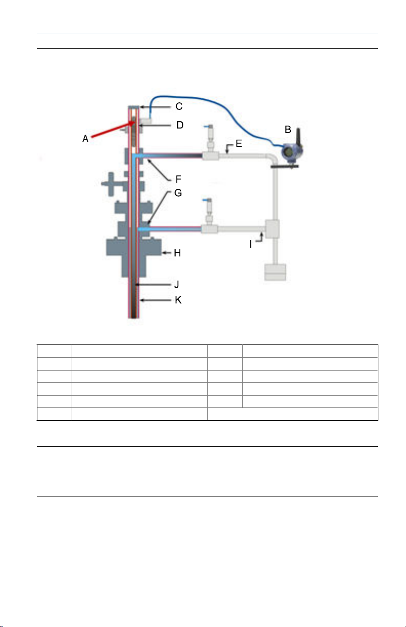
Rosemount 702 Transmitter for Plunger ArrivalFigure A-:
A Plunger Arrival Sensor (ETC Cyclops) G Lower Lubricator Outlet
B 702 Plunger Arrival H Well Casing
C Lubricator I Production gas
D Plunger J Well casing/production tube
E Wastewater K Well casing
F Upper Lubricator Outlet
Contents
Wireless considerations ................................ 4
Physical installation ...................................... 7
Device network configuration .....................14
3 Rosemount 702 Wireless Discrete Transmitter
Verify operation ..........................................16
Reference information: wiring switch inputs,
output circuits, and leak sensors ................. 20
Safety shower and eye wash
monitoring ................................................. 39
Product Certifications ................................. 42
Page 4
Quick Start Guide April 2018
1 Wireless considerations
1.1 Power up sequence
The Smart Wireless Gateway should be installed and functioning properly
before any wireless field devices are powered. Install the Black Power Module,
SmartPower™ Solutions model number 701PBKKF (part number
00753-9220-0001) into the Rosemount 702 Transmitter to power the
device. Wireless devices should be powered up in order of proximity from the
Gateway, beginning with the closest device, then working outward from the
Gateway. This results in a simpler and faster network installation. Enable
Active Advertising on the Gateway to ensure new devices are able to join the
network faster. For more information see the Emerson™ Wireless 1420
Gateway Reference Manual.
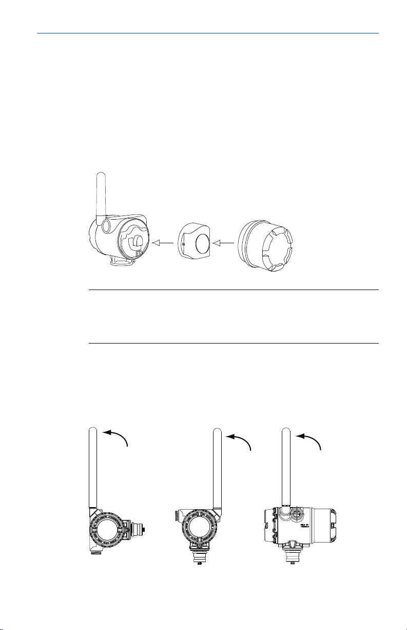
1.2
Antenna position
The antenna should be positioned vertically, either straight up or straight
down, and it should be approximately 3 ft. (1 m) from any large structure,
building, or conductive surface to allow for clear communication to other
devices.
Antenna PositionFigure 1-1:
4 Rosemount 702 Wireless Discrete Transmitter
Page 5
$
$
April 2018
1.3 Conduit entry
Upon installation, ensure each conduit entry is either sealed with a conduit
plug using approved thread sealant, or has an installed conduit fitting or
cable gland with appropriate threaded sealant. Note the conduit entries on
the Rosemount 702 Transmitter are threaded ½–14 NPT.
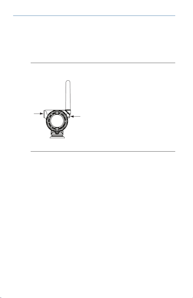
Conduit EntryFigure 1-2:
A. Conduit entry
Quick Start Guide
1.4
Quick Start Guide 5
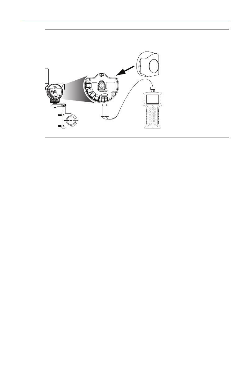
Field Communicator connections
The power module needs to be installed before the Field Communicator can
interface with the Rosemount 702 Transmitter. This transmitter uses the
Black Power Module; Order model number 701PBKKF or part number
00753-9220-0001.
Page 6
COMM
P/N 00753-9200-0020
1
2
3
4
CH1 +
CMN
CH2 +
CMN
CH Input Mode:
Dry Contact Only
CH Output Mode:
26VDC Max
100mA Max
Quick Start Guide
The Rosemount 702 Transmitter and all other wireless devices should not be
set up until after the Smart Wireless Gateway has been installed and is
functioning properly.
April 2018
Connection DiagramFigure 1-3:
6 Rosemount 702 Wireless Discrete Transmitter
Page 7
April 2018
2 Physical installation
The Rosemount 702 Transmitter can be installed in one of two
configurations:
• Direct mount, where the switch is connected directly to the Rosemount
702 Transmitter housing’s conduit entry.
• Remote mount, where the switch is mounted separate from the
Rosemount 702 Transmitter housing, then connected to the Rosemount
702 Transmitter via conduit.
Select the installation sequence that corresponds to the mounting
configuration.
Quick Start Guide
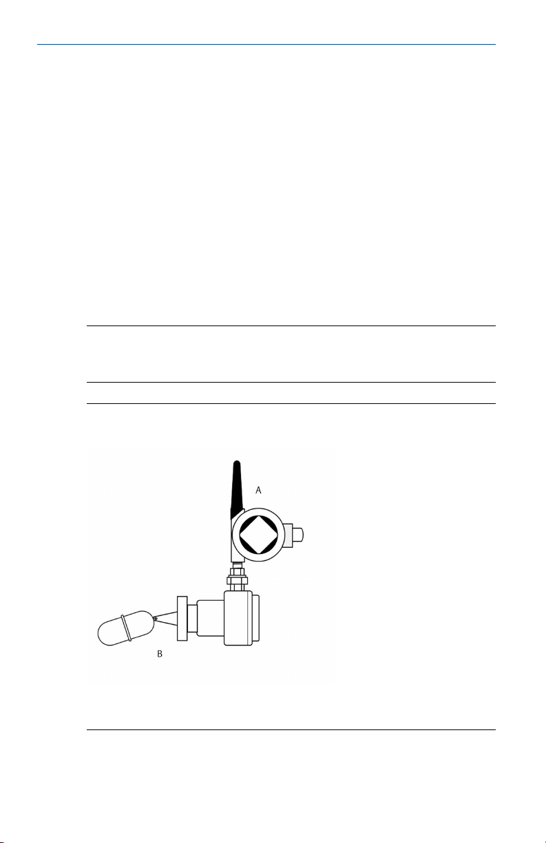
2.1
Direct mount
Note
Direct mount installation should not be employed when using tubing and
connectors such as Swagelok® fittings.
Direct MountFigure 2-1:
A. Rosemount 702 Transmitter
B. Float switch
Quick Start Guide 7
Page 8
Quick Start Guide
Procedure
1. Install the switch according to standard installation practices making sure
to use thread sealant on all connections.
2. Attach the Rosemount 702 Transmitter housing to the switch using the
threaded conduit entry.
3. Attach the switch wiring to the terminals as indicated on the wiring
diagram (see Chapter 5).
4. Connect the Black Power Module.
Note
Wireless devices should be powered up in order of proximity from the
Smart Wireless Gateway, beginning with the closest device to the
Gateway. This will result in a simpler and faster network installation.
April 2018
5. Close the housing cover and tighten to safety specification. Always
ensure a proper seal so the metal touches metal, but do not over tighten.
6. Position antenna vertically, either straight up or straight down. The
antenna should be approximately 3 ft. (0.91 m) from any large structures
or buildings, to allow clear communication to other devices.
8 Rosemount 702 Wireless Discrete Transmitter
Page 9
April 2018
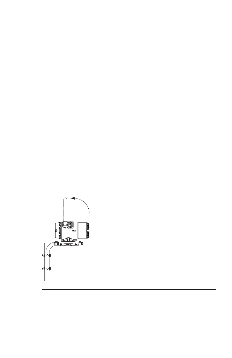
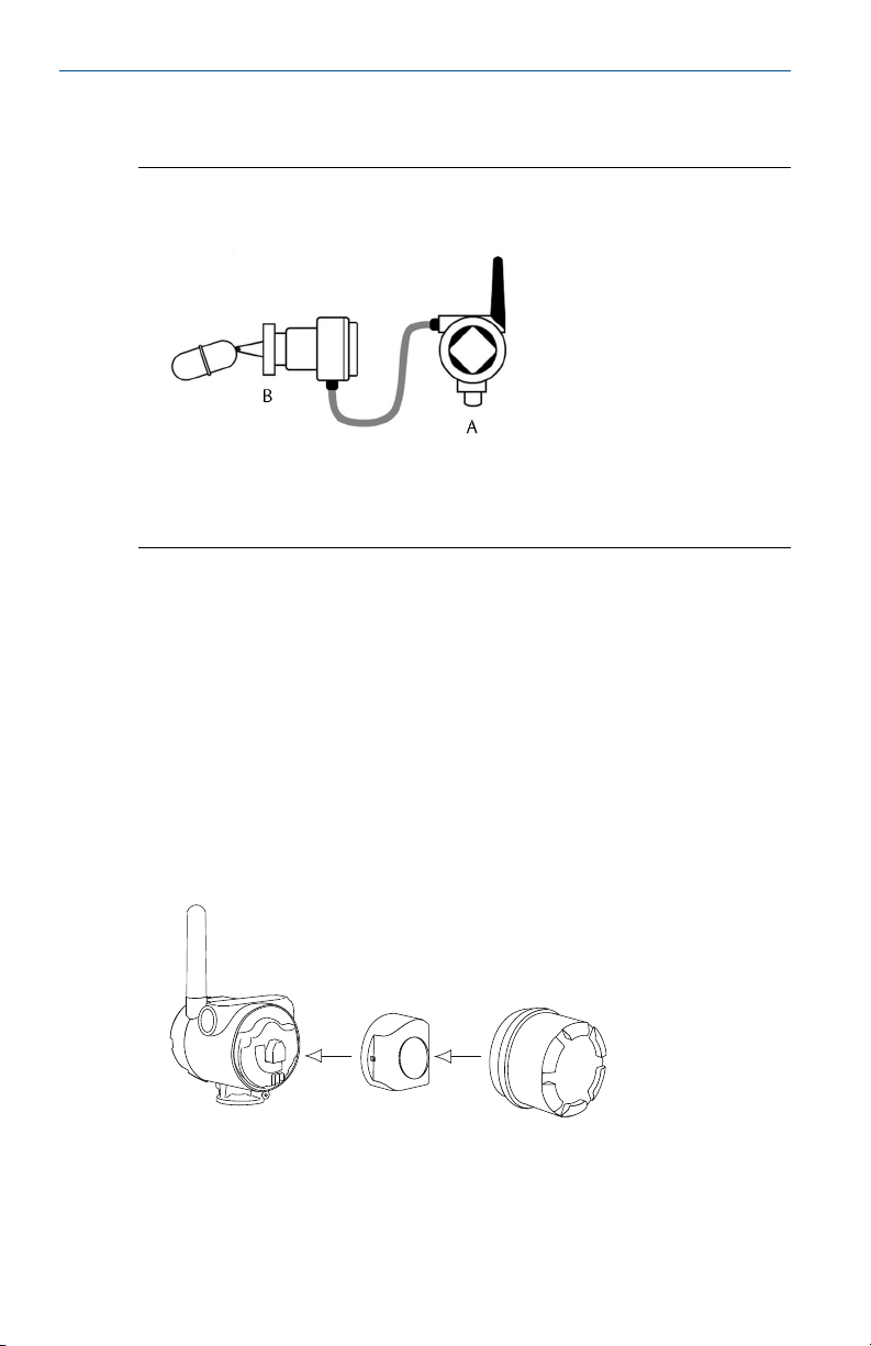
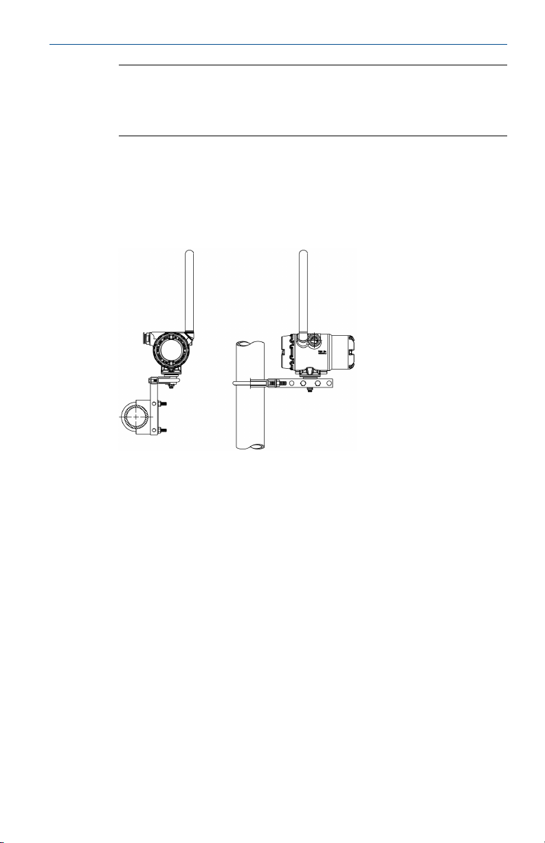
2.2 Remote mount
Remote MountFigure 2-2:
A. Rosemount 702 Transmitter
B. Float switch
Procedure
1. Install the switch according to standard installation practices making sure
to use thread sealant on all connections.
2. Run wiring (and conduit if necessary) from the switch to the Rosemount
702 Transmitter.
3. Pull the wiring through the threaded conduit entry of the Rosemount 702
Transmitter.
4. Attach the switch wiring to the terminals as indicated on the wiring
diagram (see Chapter 5).
5. Connect the black power module.
Quick Start Guide
Quick Start Guide 9
Page 10
Quick Start Guide
Note
Wireless devices should be powered up in order of proximity from the
Smart Wireless Gateway, beginning with the closest device to the
gateway. This will result in a simpler and faster network installation.
6. Close the housing cover and tighten to safety specification. Always
ensure a proper seal so the metal touches metal, but do not over tighten.
7. Position antenna vertically, either straight up or straight down. The
antenna should be approximately 3 ft. (0.91 m) from any large structures
or buildings, to allow clear communication to other devices.
April 2018
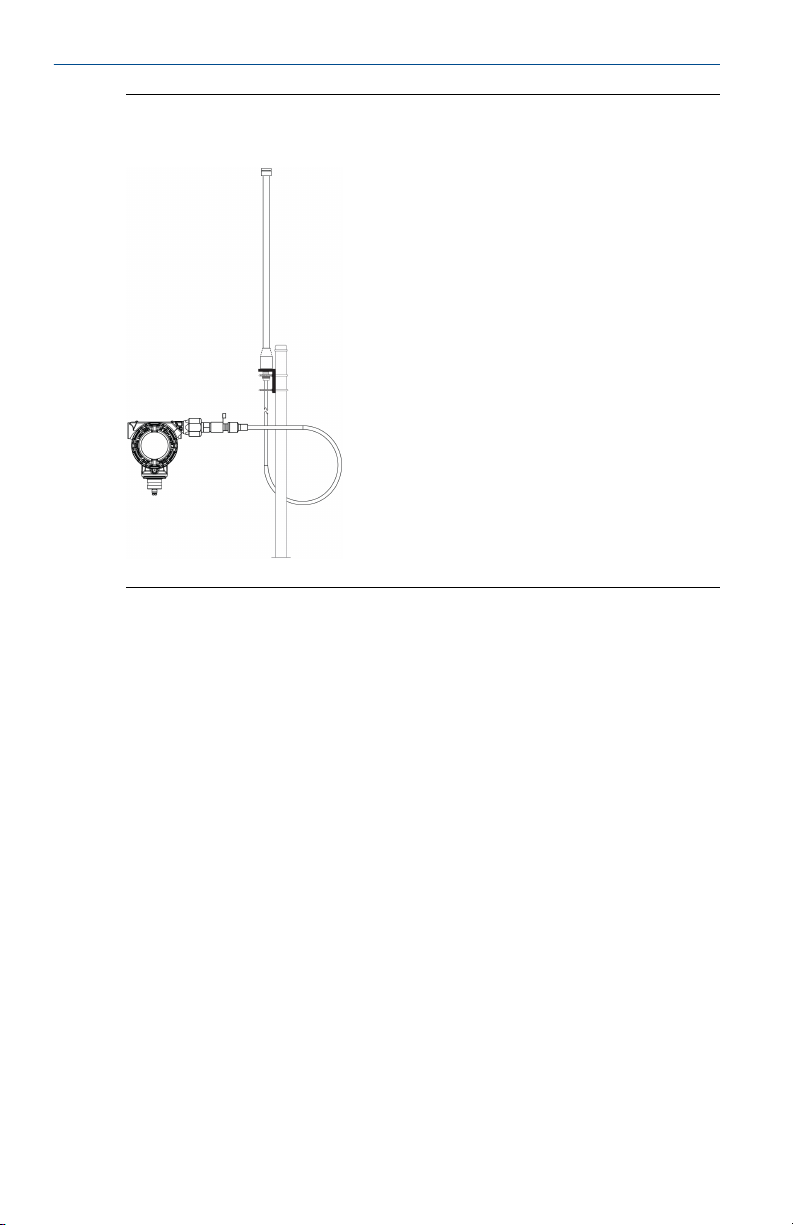
2.3 High gain, remote antenna (optional)
The high gain, remote antenna options provide flexibility for mounting the
Rosemount 702 Transmitter based on wireless connectivity, lightning
protection, and current work practices.
10 Rosemount 702 Wireless Discrete Transmitter
Page 11
April 2018
Quick Start Guide
Figure 2-3:
Rosemount 702 Transmitter with High Gain, Remote
Antenna
2.3.1 Install the high gain, remote antenna (WN option)
Prerequisites
Find a location where the remote antenna has optimal wireless performance.
Ideally this will be 15–25 ft. (4.6–7.6 m) above the ground or 6 ft. (2 m)
above obstructions or major infrastructure.
Quick Start Guide 11
Page 12

Quick Start Guide
WARNING!
When installing remote mount antennas for the Rosemount 702 Transmitter,
always use established safety procedures to avoid falling or contact with
high-power electrical lines.
Install remote antenna components for the Rosemount 702 Transmitter in
compliance with local and national electrical codes and use best practices for
lightning protection.
Before installing, consult with the local area electrical inspector, electrical
officer, and work area supervisor.
The Rosemount 702 Transmitter remote antenna option is specifically
engineered to provide installation flexibility while optimizing wireless
performance and local spectrum approvals. To maintain wireless
performance and avoid non-compliance with spectrum regulations, do not
change the length of cable or the antenna type.
If the supplied remote mount antenna kit is not installed per these
instructions, Emerson is not responsible for wireless performance or noncompliance with spectrum regulations.
Procedure
April 2018
1. Mount the antenna on a 1.5 to 2-in. pipe mast using the supplied
mounting equipment.
2. Connect the lightning arrestor directly to the top of the Rosemount 702
Transmitter.
3. Install the grounding lug, lock washer, and nut on top of lightning
arrestor.
4. Connect the antenna to the lightning arrestor using the supplied
LMR-400 coaxial cable ensuring the drip loop is not closer than 1 ft. (0.3
m) from the lightning arrestor.
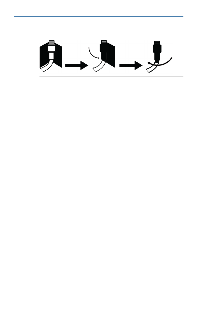
5. Use the coaxial sealant to seal each connection between the wireless field
device, lightning arrestor, cable, and antenna.
Note
The remote mount antenna kit includes coaxial sealant for
weatherproofing the cable connections for the lightning arrestor,
antenna, and Rosemount 702 Transmitter. Coaxial sealant must be
applied to guarantee performance of the wireless field network. See
Figure 2‐4 for details on how to apply coaxial sealant.
12 Rosemount 702 Wireless Discrete Transmitter
Page 13
April 2018
Quick Start Guide
Applying Coaxial Sealant to Cable ConnectionsFigure 2-4:
6. Ensure the mounting mast and lightning arrestor are grounded according
to local/national electrical code.
Any spare lengths of coaxial cable should be placed in 12-in. (0.3 m) coils.
Quick Start Guide 13
Page 14
Quick Start Guide
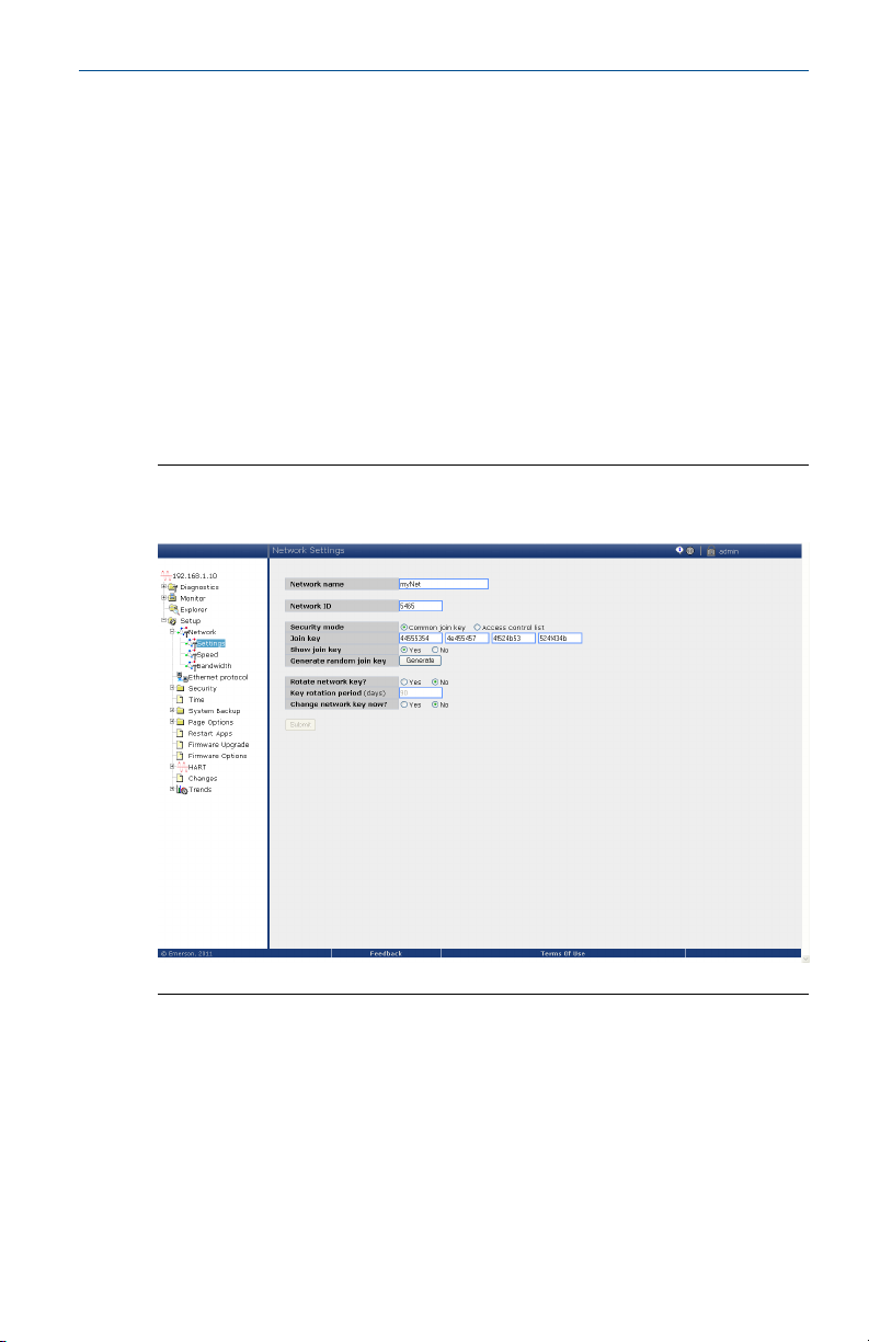
3 Device network configuration
In order to communicate with the Smart Wireless Gateway, and ultimately
the host system, the transmitter must be configured to communicate with
the wireless network. This step is the wireless equivalent of connecting wires
from a transmitter to the information system. Using a Field Communicator or
AMS Wireless Configurator, enter the Network ID and Join Key so they match
the Network ID and Join Key of the Gateway and other devices in the
network. If the Network ID and Join Key do not match that of the Gateway,
the Rosemount 702 Transmitter will not communicate with the network. The
Network ID and Join Key may be obtained from the Smart Wireless Gateway
on the Setup Network Settings page on the web interface, shown in
Figure 3‐1.
Gateway Network SettingsFigure 3-1:
April 2018
3.1 AMS Wireless Configurator
1. Right click on the Rosemount 702 Transmitter.
2. Select Configure.
3. When the menu opens, select Join Device to Network.
4. Follow the method to enter the Network ID and Join Key.
14 Rosemount 702 Wireless Discrete Transmitter
Page 15

April 2018 Quick Start Guide
3.2 Field Communicator
The Network ID and Join Key may be changed in the wireless device by using
the following Fast Key sequence. Set both Network ID and Join Key.
Function Fast Key sequence Menu items
Wireless setup 2,2,1 Network ID, Join Device to Network
Quick Start Guide 15
Page 16
N E T w K
S R C H N G
n e t w k
N E G O T
n e t w k
L I M - O P
n e t w k
O K
Quick Start Guide April 2018
4 Verify operation
There are four ways to verify operation: using the optional local display (LCD),
using the Field Communicator, using the Smart Wireless Gateway’s
integrated web interface, or by using AMS Suite Wireless Configurator. If the
Rosemount 702 Transmitter was configured with the Network ID and Join
Key, and sufficient time has passed, the transmitter will be connected to the
network.
4.1 Local display
4.1.1 Start-up sequence
When the Rosemount 702 Transmitter is first powered up, the LCD display
will display a sequence of screens: All Segments On, Device Identification,
Device Tag, and then the user chosen variables of the periodic display.
During steady state operation, the LCD display gives a periodic display of user
chosen variables at the configured wireless update rate. These variables can
be selected from a list of six:
• Channel 1 State
• Channel 1 Count
• Channel 2 State
• Channel 2 Count
• Electronics Temperature
• Supply Voltage
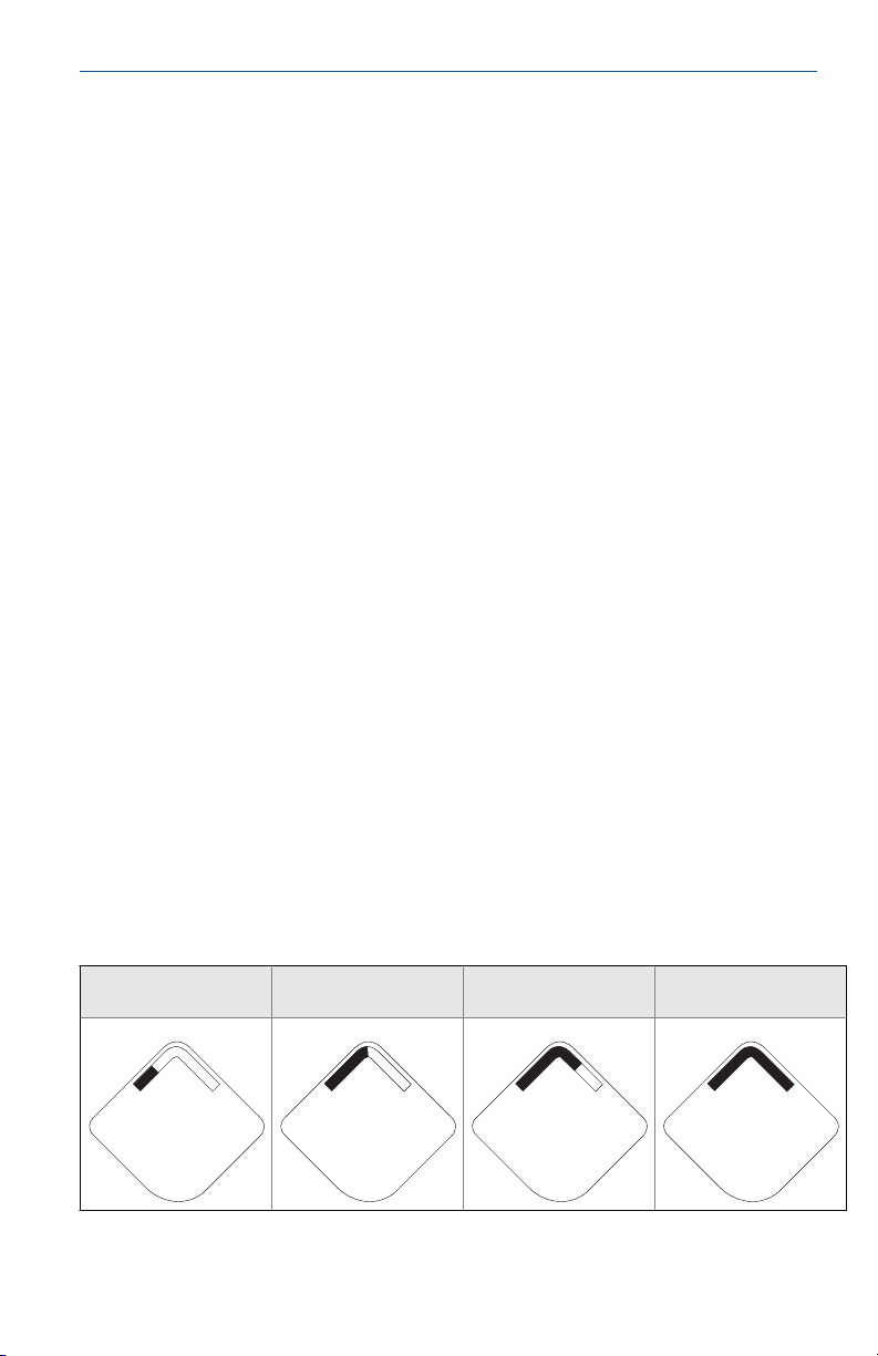
Refer to the Rosemount 702 Reference Manual for error codes and other LCD
display messages. The chevron-shaped status bar at the top of the screen
indicates the progress of the network join process. When the status bar is
filled, the device is successfully connected to the wireless network.
Searching for network
16 Rosemount 702 Wireless Discrete Transmitter
Joining network
Connected with limited
bandwidth Connected
Page 17

April 2018
4.2 Field Communicator
For HART® Wireless transmitter communication, a Rosemount 702
Transmitter DD is required.To obtain the latest DD, visit the Emerson Easy
Upgrade site at: Emerson.com/Device‐Install‐Kits.
Function Key sequence Menu items
Communications 3, 3 Join Status, Wireless Mode, Join Mode, Number of Available
Neighbors, Number of Advertisements Heard, Number of
Join Attempts
4.3 Smart Wireless Gateway
In the Gateway’s integrated web server, navigate to the Explorer page. This
page shows whether the device has joined the network and is
communicating properly.
Note
It may take several minutes for the device to join the network.
Note
If the device joins the network and immediately has an alarm present, it is
likely caused by the sensor configuration. Check the sensor wiring (see
Figure 5‐1) and the sensor configuration (see Table 5‐6).
Quick Start Guide
Quick Start Guide 17
Page 18

Quick Start Guide April 2018
Smart Wireless Gateway Explorer PageFigure 4-1:
4.4 AMS Wireless Configurator
When the device has joined the network, it will appear in AMS Wireless
Configurator as illustrated below.
AMS Wireless Configurator, Device Explorer ScreenFigure 4-2:
18 Rosemount 702 Wireless Discrete Transmitter
Page 19

April 2018
4.5 Troubleshooting
If the device is not joined to the network after power up, verify the correct
configuration of the Network ID and Join Key, and that Active Advertising has
been enabled on the Smart Wireless Gateway. The Network ID and Join Key in
the device must match the Network ID and Join Key of the Gateway.
Procedure
1. From the Gateway's integrated web interface, select Setup Network
Settings to obtain the Network ID and Join Key (see Figure 4‐3).
Gateway Network SettingsFigure 4-3:
Quick Start Guide
2. To change the Network ID and Join Key in the wireless device, use a Field
Communicator and enter the following Fast Key sequence.
Function
Wireless 2, 1, 1 Join Device to Network
Fast Key sequence Menu items
3. Follow the on screen prompts.
Quick Start Guide 19
Page 20

Quick Start Guide
April 2018
5 Reference information: wiring switch inputs,
output circuits, and leak sensors
5.1 Dry contact switch inputs
The Rosemount 702 Transmitter has a pair of screw terminals for each of two
channels, and a pair of communication terminals. These terminals are labeled
as follows:
CH1+: Channel one positive
CMN: Common
CH2+: Channel two positive
CMN: Common
COMM: Communication
Rosemount 702 Transmitter TerminalFigure 5-1:
5.2 Wireless output specifications
5.2.1 Dual input
The Rosemount 702 Transmitter will accept the input from one or two single
pole single throw switches on inputs CH1 and CH2. The wireless output of
the transmitter will be both a primary variable (PV) and a secondary variable
20 Rosemount 702 Wireless Discrete Transmitter
Page 21

April 2018
Quick Start Guide
(SV). The PV is determined by the CH1 input. The SV is determined by the
CH2 input. A closed switch drives a TRUE output. An Open switch drives a
FALSE output.
Note
Any dry contact input may optionally be inverted by the device, so change
the discrete logic state. This is useful, for instance, if a normally open switch
is used to replace a normally closed switch.
Single and Dual InputFigure 5-2:
A. Single Input
B. Dual Input
Single or Dual InputTable 5-1:
Switch input Wireless output Switch input Wireless output
CH1 PV CH2 SV
Closed TRUE (1.0) Closed TRUE (1.0)
Open FALSE (0.0) Open FALSE (0.0)
5.2.2 Dual input, limit contact logic
When configured for Limit Contact Logic, the Rosemount 702 Transmitter
will accept the input from two single pole single throw switch on inputs CH1
and CH2, and will use limit contact logic for the determination of the wireless
outputs.
Quick Start Guide 21
Page 22

Quick Start Guide
A. TRUE
B. FALSE
Switch input Wireless output
CH1 CH2 PV SV
Open Open TRAVEL (0.5) TRAVEL (0.5)
Open Closed FALSE (0.0) FALSE (0.0)
Closed Open TRUE (1.0) TRUE (1.0)
Closed Closed FAULT(NaN) FAULT(NaN)
April 2018
Dual Input, Limit ContactsFigure 5-3:
Dual Input, Limit Contact LogicTable 5-2:
5.2.3 Dual input, opposing contact logic
When configured for Opposing Contact Logic, the Rosemount 702
Transmitter will accept the input from a double pole single throw switch on
inputs CH1 and CH2, and will use opposing contact logic for the
determination of the wireless outputs.
22 Rosemount 702 Wireless Discrete Transmitter
Page 23

April 2018
Quick Start Guide
Dual Input, Opposing ContactFigure 5-4:
A. TRUE
B. FALSE
Dual input, Opposing Contact LogicTable 5-3:
Switch inputs Wireless outputs
CH1 CH2 PV SV
Open Open FAULT(NaN) FAULT(NaN)
Open Closed FALSE (0.0) FALSE (0.0)
Closed Open TRUE (1.0) TRUE (1.0)
Closed Closed FAULT(NaN) FAULT(NaN)
5.3 Momentary discrete inputs, measurement option code 32 and 42
The Rosemount 702 Transmitter is capable of detecting momentary discrete
inputs of 10 milliseconds or more in duration, regardless of the wireless
update rate. At each wireless update, the device reports current discrete
input state along with an accumulating count of close-open cycles for each
input channel.
Quick Start Guide 23
Page 24

Quick Start Guide
A. Input Switch State
B. Closed
C. Open
D. State
E. Count
F. Wireless Updates
April 2018
Momentary Inputs and Accumulating CountFigure 5-5:
Figure 5-6:
Reporting of Current Discrete State and Count in AMS Device
Manager
A. Current State
B. Count
24 Rosemount 702 Wireless Discrete Transmitter
Page 25

April 2018
5.3.1 Setting variable reporting
The Rosemount 702 Transmitter has two choices for variable reporting:
Classic - Discrete State Only, or Enhanced – Discrete State and Count.
1. In AMS Device Manager, select Configure > Manual Setup > HART.
2. Set Variable Reporting as desired.
Option Description
Classic - Discrete State
Only
Enhanced – Discrete
State with Count
Table 5‐4 shows the variable mapping for both cases.
Variable MappingTable 5-4:
Variable reporting PV SV TV QV
Classic – Discrete State Only CH1 State CH2 State Electronics tem-
Enhanced – Discrete State
with Count
The Rosemount 702 Transmitter will report variables exactly like
the previous version of the device (measurement option code
22).
The Rosemount 702 Transmitter will provide both current state
of the discrete channels, and a count of the discrete state
change cycles.
Quick Start Guide
Supply voltage
perature
CH1 State CH2 State CH1 Count CH2 Count
5.4 Discrete output circuits, measurement option code 42
The Rosemount 702 Transmitter has two channels that can each be
configured for discrete input or output. Inputs must be dry contact switch
inputs and these were described in a preceding section of this document.
Outputs are a simple switch closure to activate an output circuit. The
Rosemount 702 Transmitter output does not provide any voltage or current,
the output circuit must have power of its own. The Rosemount 702
Transmitter output has maximum switch capacity per channel of 26 volts DC
and 100 milliamps.
Note
It is very important that the polarity of the output circuit is as shown in the
wiring diagrams, with the positive (+) side of the circuit wired to the +
terminal of each channel, and the negative (-) side of the circuit wired to the
CMN terminal. If the output circuit is wired backwards it will remain active
(switch closed) regardless of the state of the output channel.
Quick Start Guide 25
Page 26

Quick Start Guide
5.5 Discrete output switch functionality
The discrete output of the Rosemount 702 Transmitter is driven by the host
control system, through the Smart Wireless Gateway, and out to the
Rosemount 702 Transmitter. The time required for this wireless
communication from the Gateway to the Rosemount 702 Transmitter is
dependent on many factors, including the size and topology of the network
and the total amount of downstream traffic on the wireless network. For a
network that is constructed to our best practices, typical delays in
communication of a discrete output from the Gateway to the Rosemount
702 Transmitter are 15 seconds or less. Remember that this delay is only part
of the latency that well be observed in a control loop.
Note
The output switch functionality of the Rosemount 702 Transmitter requires
that the network is managed by a version 4 Smart Wireless Gateway, with
v4.3 or greater firmware installed.
Output Circuit WiringFigure 5-7:
April 2018
A. LOAD
B. OUTPUT
26 Rosemount 702 Wireless Discrete Transmitter
Page 27

April 2018
Quick Start Guide
Possible Configurations for Both Channel 1 and Channel 2Figure 5-8:
A. INPUT
B. LOAD
C. OUTPUT
5.6
Quick Start Guide 27
Special considerations for dual output circuits
If both channels are connected to output circuits, it is very important that the
CMN terminal of each circuit be at the same voltage. Employing a common
ground for both output circuits is one way to ensure that both circuits have
CMN terminals at the same voltage.
Page 28

Quick Start Guide
A. LOAD
B. OUTPUT
If two output circuits are connected to a single Rosemount 702 Transmitter
with a single power supply, both CH + and CMN terminals must be connected
to each output circuit. The negative power supply wires must be at the same
voltage and connected to both CMN terminals.
April 2018
Dual Output Circuits with a Common GroundFigure 5-9:
Dual Output Circuits with One Power SupplyFigure 5-10:
A. LOAD
B. OUTPUT
28 Rosemount 702 Wireless Discrete Transmitter
Page 29

April 2018 Quick Start Guide
5.7 Switching greater currents or voltages
It is important to note that the maximum output switching capacity is 26
volts DC and 100 milliamps. If a greater voltage or current is to be switched,
an interposing relay circuit can be used. Figure 5‐11 shows an example of a
circuit to switch higher currents or voltages.
Wiring an Interposing Relay to Switch Greater Currents or
Voltages
5.8
Figure 5-11:
A. Power Supply
B. LOAD
Plunger arrival detection
5.8.1 Terminal block connections
The plunger arrival detection configuration for measurement option code 52
is intended for use with the ETC Cyclops Plunger Arrival Sensor.
Plunger Arrival Terminal DiagramFigure 5-12:
Quick Start Guide 29
Page 30

1
2
3
3
2
1
Quick Start Guide
The wiring connections to the ETC Cyclops sensor are made according to
Figure 5-13, where 1 connects to 3, 2 connects to 2, and 3 connects to 1
between the transmitter and the sensor.
Plunger Arrival Sensor ETC Cyclops Sensor
April 2018
Wiring ConfigurationFigure 5-13:
Rosemount 702 Transmitter ETC Cyclops Sensor
1. PWR OUT
2. SIG
3. COM
1. COM
2. SIG
3. PWR
For mounting and maintenance of the ETC Cyclops Sensor, refer to the ETC
Cyclops Plunger Arrival Sensor Manual.
5.8.2 Latching feature
The Rosemount 702 has a latching feature that, when enabled, allows
detection of momentary state changes to be held for a configurable latch
period. The latching feature can be configured to detect either high or low
state changes. By default, the Plunger state (channel 1) is enabled to latch
high state changes for a period of one minute.
The following are some examples to demonstrate how the latching time
works.
30 Rosemount 702 Wireless Discrete Transmitter
Hold time is set to four seconds for illustration in the following examples.
Note
Page 31

A
B
A
B
A
B
April 2018
Quick Start Guide
Short events (less than latch hold time) of the measured value will be latched
to the reported value for the duration of latch hold time.
Latch Time Short EventsFigure 5-14:
A. Measured
B. Reported
The start of the ltach hold timer begins when the measured signal first
transitions to active state.
Latch Hold Time StartFigure 5-15:
A. Measured
B. Reported
The latch only applies to transitions into the active state. As soon as the
reported value is no longer latched,the devices is armed for the next event.
Latch Applies to Transitions to Active StateFigure 5-16:
A. Measured
B. Reported
If the measured value goes inactive and active again before the initial latch
hold timer experies, the latch hold timer will restart from the beginning of
the most recent event.
Quick Start Guide 31
Page 32

A
B
Quick Start Guide
Latch Hold Timer RestartsFigure 5-17:
A. Measured
B. Reported
5.8.3 Latching warnings
WARNING!
When state latching is enabled, the discrete variable reported to the system
will represent the latched value which may not be the actual state value
measured by the Rosemount 702 Transmitter
WARNING!
Ensure that the state latch time value is long enough for the value to be
reported throughout the entire system to guarantee the state transition is
not missed. After configuring discrete latching function, check for proper
operation at the system level to ensure the desired state transitions are
captured as desired.
5.8.4 System Verification
April 2018
After installation of the 702DX52 for plunger arrival one must verify
functionality.
• Verify the sensor: To do so, pass a ferrous object (ex. Wrench) past the
cyclops sensor to simulate an arrival. Verify via the LCD screen and/or
field communicator that channel 1 indicates a state change. If a state
change is seen, sensor wiring is correct; if nothing is seen, please go back
through the installation steps and confirm that everything has been done
accordingly.
• Verify System integration: It is important to verify the latch time is
configured correctly. The default latch period is set to one minute. Verify
the host system can detect the arrival event by moving a ferrous metal
object (ex. Wrench) past the arrival sensor. The signal should be passed
from the device, through the Wireless Gateway and detected at the final
host application (ex. PLC, Modbus/OPC, etc.). If nothing is seen, confirm
the latch time is appropriate considering the full system scan cycle.
32 Rosemount 702 Wireless Discrete Transmitter
Page 33

April 2018
5.9 Leak sensors, liquid hydrocarbon detection, measurement option code 61
5.9.1 Terminal block connections
The Liquid Hydrocarbon Detection configuration is intended for use with the
Tyco® TraceTek® Fast Fuel Sensor, or TraceTek sensing cable.
Fuel Sensor TerminalFigure 5-18:
Quick Start Guide
Fuel Sensor ConnectionFigure 5-19:
5.9.2 Connecting to the fast fuel sensor and TraceTek sensing cable
The connections to the Fast Fuel Sensor TraceTek sensing cable are made by
matching the appropriately colored wires to the matching colored
termination lugs.
Quick Start Guide 33
Page 34

$
&
'
(
)
%
Quick Start Guide
Note
All part numbers associated with the fuel sensor cable wiring refer to
products sold by Tyco Thermo Controls, LLC.
The Rosemount 702 Wireless Discrete Transmitter can support up to 3 Fast
Fuel sensors. These Fast Fuel sensors are connected using TraceTek Modular
Leader Cable (TT-MLC-MC-BLK), optional modular jumper cables (TT-MJC-xxMC-BLK) and branching connectors (TT-ZBC-MC-BLK) as suggested in
Figure 5‐20.
April 2018
Fuel Sensor WiringFigure 5-20:
A. TT‐MLC‐MC‐BLK (Leader cable)
B. TT‐FFS‐100 or TT‐FFS‐250 (Fast fuel sensor probe)
C. TT‐MLC‐MC‐BLK (Leader cable)
D. TT‐MJC‐xx‐MC‐BLK (Optional jumper cable)
E. TT‐ZBC‐xx‐MC‐BLK (Branch connector)
F. TT‐FFS‐100 or TT‐FFS‐250 (Fast fuel sensor probe)
The Rosemount 702 Wireless Discrete Transmitter can support up to 500
feet of TraceTek hydrocarbon or solvent sensor cable (TT5000 or TT5001
series). The total amount of sensor cable connected to a single Rosemount
34 Rosemount 702 Wireless Discrete Transmitter
702 Transmitter is not to exceed 500 ft. (150 m). However leader cable,
jumper cables (if used) and branch connectors are not included in the 500
foot limit. See Figure 5‐21 for typical configurations.
Page 35

$
'
(
)
+*
%
&
April 2018
Quick Start Guide
Fuel Sensor Cable WiringFigure 5-21:
A. TT‐MLC‐MC‐BLK (Leader Cable)
B. TT5000/TT5001 Sensor cable (up to 500 ft.)
C. TT‐MET‐MC (End termination)
D. TT‐MJC‐xx‐MC‐BLK (Optional jumper cable)
E. TT‐ZBC‐xx‐MC‐BLK (Branch connector)
F. TT‐MET‐MC (End termination)
G. TT‐MET‐MC (End termination)
H. Up to 500‐ft. TT5000 or TT5001 sensor cable (Total per 702)
Important notes regarding the use of Tyco TraceTek Fast Fuel Sensor and
TraceTek sensing cable:
• Tyco TraceTek sensors must be installed as per manufacturer
recommendations.
• Do not run the Rosemount 702 Transmitter for long periods (more than
two weeks) with a Tyco fuel sensor in the leak state as this will more
rapidly deplete the power module.
5.9.3 Liquid hydrocarbon detection interface, for Modbus® mapping
Table 5‐5 describes use of the Rosemount 702 Transmitter for hydrocarbon
Quick Start Guide 35
detection in other communications protocols such as Modbus or OPC. It is
imperative that both PV and SV be mapped to the host system so as to make
a good interpretation of the condition and status of the leak detector.
Page 36

Quick Start Guide
April 2018
Table 5-5:
Liquid Hydrocarbon Detection Interface, for Modbus
Mapping
PV SV Description/interpretation
1.0 1.0 Normal condition, no leak detected, sensor status good
0.0 1.0 or 0.0 Leak detected, sensor status good
1.0 0.0 Sensor Not Connected, Assume Leak, take appropriate action
NOTICE
It is imperative that both PV and SV be mapped to the host system so the
diagnostic information on the sensor status is captured.
In addition, system considerations must be observed to ensure that the
device is still connected to the wireless network and reporting values. On an
Emerson Smart Wireless Gateway, this can be done by referring to the
parameter: PV_HEALTHY. PV_HEALTHY has a “True” state when the device is
on the network and its updates are current, not late or stale, and the device is
functioning properly. A “False” state of PV_HEALTHY means the device is
either off the network, the data updates are not current, or that there is a
malfunction of the device (such as an electronics failure). In the case of a
“False” state of PV_HEALTHY, it is recommended to assume the device is not
connected to the network and take appropriate action.
Mapping the PV, SV, and PV_HEALTHY variables and parameter
Below is a the Gateway screen where the PV, SV, and PV_HEALTHY variables
and parameter can be mapped.
36 Rosemount 702 Wireless Discrete Transmitter
Page 37

April 2018 Quick Start Guide
Smart Wireless Gateway Modbus Register MapFigure 5-22:
The Fast Fuel Sensor Diagnostics will propagate via the SV variable. This
additional information will provide additional sensor Status information while
using the TraceTek Fast Fuel Sensor.
WARNING!
If a device is not present on the wireless network, appropriate action must be
taken by the host system.
5.10
Quick Start Guide 37
Field Communicator use
Note
In order to communicate with a Field Communicator, power the Rosemount
702 Transmitter by connecting the power module.
Rosemount 702 Transmitter Fast Key SequenceTable 5-6:
Function
Device information
Fast Key sequence Menu items
2, 2, 4, 3 Manufacturer Model, Final Assembly Number, Universal,
Field Device, Software, Hardware, Descriptor, Message,
Date, Model Number I, II, III, SI Unit Restriction, Country
Page 38

COMM
P/N 00753-9200-0020
1
2
3
4
CH1 +
CMN
CH2 +
CMN
CH Input Mode:
Dry Contact Only
CH Output Mode:
26VDC Max
100mA Max
Quick Start Guide April 2018
Rosemount 702 Transmitter Fast Key Sequence (continued)Table 5-6:
Function
quence Menu items
Guided setup 2, 1 Join Device to Network, Configure Update Rate, Config-
ure Sensor, Calibrate Sensor, Configure Display, Configure Process Alarms
Manual setup 2, 2 Wireless, Process Sensor, Percent of Range, Device Tem-
peratures, Device Information, Device Display, Other
Wireless 2, 2, 1 Network ID, Join Device to Network, Configure Update
Rate, Configure Broadcast Power Level, Power Mode,
Power Source
Fast Key se-
Sensor calibra-
3, 4, 1 Output configuration, input configuration
tion
Field Communicator ConnectionsFigure 5-23:
38 Rosemount 702 Wireless Discrete Transmitter
Page 39

April 2018
Quick Start Guide
6 Safety shower and eye wash monitoring
The Rosemount 702 Transmitter can be used to monitor safety showers and
eye wash stations by using switch kits provided by TopWorx™, an Emerson
company. These kits are ordered as a part of the Rosemount 702 model
code, or separately as an accessory kit, and are available for both insulated
and un-insulated pipes. These kits contain the switches, brackets and cables
that are necessary to install the Rosemount 702 to monitor both the safety
shower and the eye wash in a single station. Because each has two input
channels, one Rosemount 702 Transmitter can be used to monitor both a
safety shower and an eye wash.
Each Safety Shower Monitoring kit contains:
• Two TopWorx GO™ Switch magnetic proximity switches
• Two cables, one six foot and one twelve foot
• Two black polymer cable glands
• Mounting kit for safety shower and eye wash
Safety shower monitoring
When the shower valve is activated (valve open) by pulling down on the
handle, the TopWorx switch is activated (closed switch) and the Rosemount
702 Transmitter senses that switch closure. This switch state is then
transmitted by the Rosemount 702 Transmitter to the Gateway, which then
sends that information to the control host or alert system. When the shower
valve is closed, the switch remains in the activated state until it is reset by a
technician. The switch can be re-set only by placing a ferrous metal object on
the far side of the sensing area of the switch.
Quick Start Guide 39
Page 40

Quick Start Guide
Eye wash monitoring
When the eye wash valve is activated (valve open) by pushing down on the
hand paddle, the TopWorx switch is activated (closed switch) and the
Rosemount 702 Transmitter senses that switch closure. This switch state is
then transmitted by the Rosemount 702 Transmitter to the Gateway, which
then sends that information to the control host or alert system. When the
eye wash valve is closed, the switch remains in the activated state until it is
reset by a technician. The switch can be re-set only by placing a ferrous metal
object on the far side of the sensing area of the switch.
April 2018
TopWorx Switch Installed on a Safety ShowerFigure 6-1:
40 Rosemount 702 Wireless Discrete Transmitter
Page 41

April 2018 Quick Start Guide
TopWorx Switch Installed on an Eye Wash StationFigure 6-2:
Quick Start Guide 41
Page 42

Quick Start Guide April 2018
7 Product Certifications
Rev 1.0
7.1 European directive information
A copy of the EU Declaration of Conformity can be found at the end of the
Quick Start Guide. The most recent revision of the EU Declaration of
Conformity can be found at Emerson.com/Rosemount.
7.2 Telecommunication compliance
All wireless devices require certification to ensure that they adhere to
regulations regarding the use of the RF spectrum. Nearly every country
requires this type of product certification. Emerson is working with
governmental agencies around the world to supply fully compliant products
and remove the risk of violating country directives or laws governing wireless
device usage.
7.3
7.4
7.5
7.6
FCC and IC
This device complies with Part 15 of the FCC Rules. Operation is subject to
the following conditions: This device may not cause harmful interference.
This device must accept any interference received, including interference
that may cause undesired operation. This device must be installed to ensure
a minimum antenna separation distance of 20 cm from all persons.
Ordinary location certification
As standard, the transmitter has been examined and tested to determine
that the design meets the basic electrical, mechanical, and fire protection
requirements by a nationally recognized test laboratory (NRTL) as accredited
by the Federal Occupational Safety and Health Administration (OSHA).
Installing equipment in North America
The US National Electrical Code® (NEC) and the Canadian Electrical Code
(CEC) permit the use of Division marked equipment in Zones and Zone
marked equipment in Divisions. The markings must be suitable for the area
classification, gas, and temperature class. This information is clearly defined
in the respective codes.
USA
7.6.1 I5 U.S.A. Intrinsically Safe (IS) and Non-incendive
Certificate:
42 Rosemount 702 Wireless Discrete Transmitter
[CSA] 1143113
Page 43

April 2018
Quick Start Guide
Standards:
Class 3600 - 2011,Class 3610 - 2010, Class 3611 - 2004,Class
3810 - 2005, UL 50E (11th Edition), UL 61010-1 (3rd Edition),
ANSI/ISA-60079-0 (12.00.01) - 2013, ANSI/ISA 60079-11
(12.02.01): 2014, ANSI/IEC 60529-2004
Markings:
IS CL I, DIV 1, GP, A, B, C, D; CL II, DIV 1, GP E, F, G; Class III;
Class 1, Zone 0 AEx ia IIC Ga T4; NI CL I, DIV 2, GP A, B, C, D T4;
T4(–50 °C ≤ Ta ≤ +70 °C) when installed per Rosemount
drawing 00702-1020; Type 4X/IP66/67
Special Conditions for Safe Use (X):
1. The Rosemount 702 Transmitter housing contains aluminum and is
considered a potential risk of ignition by impact or friction. Care must be
taken into account during installation and use to prevent impact and
friction.
2. The surface resistivity of the polymeric antenna is greater than 1GΩ. To
avoid electrostatic charge build-up, it must not be rubbed or cleaned with
solvents or a dry cloth.
3. The model 702 may only be used with either the 701PBKKF Rosemount
Smartpower Black Power Module or the Computational Systems, Inc.
(CSI) MHM-89004.
Sensor terminal parameters (option code
32)
UO = 6.6 V UO = 7.8 V
IO = 13.37 mA IO = 92 mA
PO = 21.77 mW PO = 180 mW
CO = 21.78 µF CO = 9.2 µF
LO = 198 mH LO = 4.2 mH
Fuel sensor terminal parameters (option
code 61)
7.6.2 N5 U.S.A. Nonincendive
Certificate:
Standards:
Markings:
Special Conditions for Safe Use (X):
1. The model 702 may only be used with either the 701PBKKF Rosemount
Smartpower Black Power Module or the Computational Systems, Inc.
(CSI) MHM-89004.
Quick Start Guide 43
[CSA] 1143113
Class 3600 - 2011, Class 3611 - 2004, Class 3810 - 2005, UL
50E (11th Edition), UL 61010-1 (3rd Edition), ANSI/IEC
60529-2004
NI CL I, DIV 2, GP A, B, C, D T4; T4(-50 °C ≤ Ta ≤ +70 °C) Type
4X/IP66/67
Page 44

Quick Start Guide April 2018
7.7 Canada
7.7.1 I6 Canada Intrinsically Safe
Certificate:
Standards:
Markings:
Special Conditions for Safe Use (X):
1. The Rosemount 702 Transmitter housing contains aluminum and is
considered a potential risk of ignition by impact or friction. Care must be
taken into account during installation and use to prevent impact and
friction.
2. The surface resistivity of the polymeric antenna is greater than 1GΩ. To
avoid electrostatic charge build-up, it must not be rubbed or cleaned with
solvents or a dry cloth.
3. The model 702 may only be used with either the 701PBKKF Rosemount
Smartpower Black Power Module or the Computational Systems, Inc.
(CSI) MHM-89004.
[CSA] 1143113
CAN/CSA C22.2 No. 0-10, CSA Std. C22.2 No. 94-M1991
(R2011), CAN/CSA Std C22.2 60079-0-11, CAN/CSA
60079-11-14, CSA Std C22.2 No. 60529:05, CAN/CSA-C22.2
No. 61010-1-12
Intrinsically Safe Class I, Division 1; Groups A, B, C, and D, T4;
suitable for Class 1, Zone 0, IIC, T4; when connected per
Rosemount drawing 00702-1020; Type 4X
7.7.2 N6 Canada Class I Division 2
Certificate:
Standards:
Markings:
[CSA] 1143113
CAN/CSA C22.2 No. 0-10, CAN/CSA C22.2 No. 94-M91, CSA
C22.2 No. 213-M1987, CSA Std C22.2 No. 60529:05
Suitable for Class 1, Division 2, Groups A, B, C, and D, T4; Cl. I,
Zone 2, IIC, T4
Special Condition for Safe Use (X):
1. The model 702 may only be used with either the 701PBKKF Rosemount
Smartpower Black Power Module or the Computational Systems, Inc.
(CSI) MHM-89004.
7.8
Europe
7.8.1 I1 ATEX Intrinsic Safety
Certificate:
Standards:
44 Rosemount 702 Wireless Discrete Transmitter
Baseefa07ATEX0239X
IEC 60079-0: 2011, IEC 60079-11: 2012
Page 45

April 2018 Quick Start Guide
Markings:
II 1 G Ex ia IIC T4 Ga, T4(-60 °C ≤ Ta ≤ +70 °C) Ex ia IIC T4 Ga,
T4(-60 °C ≤ Ta ≤ +40 °C)
For use with Rosemount SmartPower power module part number
753-9220-0001, or for use with Emerson SmartPower option 701PBKKF.
Sensor terminal parameters (option code 32)
UO = 6.51 V UO = 7.8 V
IO = 13.37 mA IO = 92 mA
PO = 21.76 mW PO = 180 mW
Ci = 0.216 µF Ci = 10 nF
CO
= 21.78 µF CO
IIC
CO
= 549.78 µF CO
IIB
COIIA = 1000 µF CO
Li = 0 Li = 0
LO
= 200 mH LO
IIC
LO
= 800 mH LO
IIB
LO
= 1000 mH LO
IIA
Special Conditions for Safe Use (X):
1. The surface resistivity of the antenna is greater than 1 GΩ. To avoid
electrostatic charge build-up, it must not be rubbed or cleaned with
solvents or a dry cloth.
7.8.2 IU ATEX Intrinsic Safety for Zone 2
Fuel sensor terminal parameters (option
code 61)
= 9.2 µF
IIC
= 129 µF
IIB
= 1000 µF
IIA
= 4.2 mH
IIC
= 16.8 mH
IIB
= 33.6 mH
IIA
Certificate:
Standards:
Markings:
Baseefa12ATEX0122X
IEC 60079-0: 2011, IEC 60079-11: 2012
II 1 G Ex ia IIC T4 Ga, T4(-60 °C ≤ Ta ≤ +70 °C)
Ex ia IIC T5 Gc, T5(-60 °C ≤ Ta ≤ +40 °C)
Sensor terminal parameters (input) Switch terminal parameters (output)
UO = 6.6 V Ui = 26 V
IO = 13.4 mA Ii = 100 mA
PO = 21.8 mW Pi = 0.65 W
CO = 10.9 µF N/A
LO = 25 µH N/A
Quick Start Guide 45
Page 46

Quick Start Guide
Special Conditions for Safe Use (X):
1. The surface resistivity of the antenna is greater than 1 GΩ. To avoid
electrostatic charge build-up, it must not be rubbed or cleaned with
solvents or dry cloth.
2. The Rosemount 701PB Power Module may be replaced in a hazardous
area. The power module has surface resistivity greater than 1 GΩ and
must be properly installed in the wireless device enclosure. Care must be
taken during transportation to and from the point of installation to
prevent electrostatic charge build-up.
7.9 International
7.9.1 I7 IECEx Intrinsic Safety
April 2018
Certificate:
Standards:
Markings:
IECEx BAS 07.0082X
IEC 60079-0: 2011, IEC 60079-11: 2011
Ex ia IIC T4 Ga, T4(-40 °C ≤ Ta ≤ +70 °C); Ex ia IIC T5 Ga,
T5(-40 °C ≤ Ta ≤ +40 °C)
Sensor terminal parameters (option code 32)
UO = 6.51 V UO = 7.8 V
IO = 13.37 mA IO = 92 mA
PO = 21.76 mW PO = 180 mW
Ci = 0.216 µF Ci = 10 nF
CO
= 21.78 µF CO
IIC
CO
= 549.78 µF CO
IIB
CO
= 1000 µF CO
IIA
Li = 0 Li = 0
LO
= 200 mH LO
IIC
LO
= 800 mH LO
IIB
LO
= 1000 mH LO
IIA
Fuel sensor terminal parameters (option
code 61)
= 9.2 µF
IIC
= 129 µF
IIB
= 1000 µF
IIA
= 4.2 mH
IIC
= 16.8 mH
IIB
= 33.6 mH
IIA
Special Conditions for Safe Use (X):
1. The surface resistivity of the antenna is greater than 1 GΩ. To avoid
electrostatic charge build-up, it must not be rubbed or cleaned with
solvents or dry cloth.
2. The Rosemount 701PBKKF Power Module may be replaced in a hazardous
area. The power modules have a surface resistivity greater than 1GΩ and
must be properly installed I the wireless device enclosure. Care must be
taken during transportation to and from the point of installation to
prevent electrostatic charge build-up.
46 Rosemount 702 Wireless Discrete Transmitter
Page 47

April 2018 Quick Start Guide
3. The Rosemount 702 enclosure may be made of aluminum alloy and given
a protective polyurethane paint finish; however, care should be taken to
protect it from impact or abrasion if located in a Zone 0 area.
7.9.2 IY IECEx Intrinsic Safety for Zone 2
Certificate:
Standards:
Markings:
IECEx BAS 12.0082X
IEC 60079-0: 2011, IEC 60079-11: 2011
Ex nA IIC T4 Gc, T4(-40 °C ≤ Ta ≤ +70 °C); Ex nA IIC T5 Gc,
T5(-40 °C ≤ Ta ≤ +40 °C)
Sensor terminal parameters (input)
UO = 6.6 V Ui = 26 V
IO = 13.4 mA Ii = 100 mA
PO = 21.8 mW Pi = 0.65 W
CO = 10.9 µF N/A
LO = 25 µH N/A
Switch terminal parameters
(output)
Special Conditions for Safe Use (X):
1. The surface resistivity of the antenna is greater than 1 GΩ. To avoid
electrostatic charge build-up, it must not be rubbed or cleaned with
solvents or dry cloth.
2. The Rosemount 701PBKKF Power Module may be replaced in a hazardous
area. The power modules have a surface resistivity greater than 1 GΩ and
must be properly installed I the wireless device enclosure. Care must be
taken during transportation to and from the point of installation to
prevent electrostatic charge build-up.
3. The Rosemount 702 enclosure may be made of aluminum alloy and given
a protective polyurethane paint finish; however, care should be taken to
protect it from impact or abrasion if located in a Zone 0 area.
7.10
China
7.10.1 I3 China Intrinsic Safety
Certificate:
Standards:
Markings:
Quick Start Guide 47
GYJ13.1238X
GB3836.1-2010, GB3836.4-2010, GB3836.20-2010
(option 32, 61): Ex ia IIC T4/T5 Ga, T4(-60 ≤ Ta ≤ 70 °C)/T5(-60
≤ Ta ≤ 40 °C)
(option 32, 42): Ex ic IIC T4/T5 Gc, T4(-60 ≤ Ta ≤ 70 °C)/T5(-60
≤ Ta ≤ 40 °C)
Page 48

Quick Start Guide April 2018
Sensor terminal parameters
(option code 32)
UO = 6.6 V UO = 6.6 V Ui = 26 V UO = 7.8 V
IO = 13.4 mA IO = 13.4 mA Ii = 100 mA IO = 92 mA
PO = 21.8 mW PO = 21.8 mW Pi = 650 mW PO = 180 mW
CO
= 21.78 µF CO = 10.9 µF N/A CO = 9.29 µF
IIC
CO
= 499.78 µF N/A N/A N/A
IIB
CO
= 1000 µF N/A N/A N/A
IIA
LO
= 200 mH LO = 0.025 mH N/A LO = 2 mH
IIC
LO
= 800 mH N/A N/A N/A
IIB
LO
= 1000 mH N/A N/A N/A
IIA
Special Conditions for Safe Use (X):
1. See certificate for special conditions.
7.11
Japan
7.11.1 I4 TIIS Intrinsic Safety
Certificates:
Markings:
TC20411 (Option 32), TC20412 (Option 61)
Ex ia IIC T4 X (-20≤ Ta ≤ +60 °C)
Terminal parameters (option code
42)
Fuel sensor terminal
parameters (option
code 61)Sensor Switch
7.12 EAC – Belarus, Kazakhstan, Russia
7.12.1 IM Technical Regulation Customs Union (EAC) Intrinsic Safety
Certificate:
Markings:
Sensor terminal parameters
(option code 32)
UO = 6.6 B UO = 6.6 B Ui, B = 26 B UO = 7.8 B
IO = 13.4 MA IO = 13.4 MA Ii, MA = 100 MA IO = 92 MA
PO = 21.8 MBT PO = 21.8 MBT Pi, BT = 650 MBT PO = 180 MBT
Ci = 216 HΦ Ci = 216 HΦ N/A Ci = 10 HΦ
CO
= 23.78 мкΦ CO
IIC
CO
= 549.78 мкΦ CO
IIB
48 Rosemount 702 Wireless Discrete Transmitter
RU C-US.Gb05.B.00578
(option 32, 61): 0Ex ia IIC T4/T5 X, T4(-60 °C ≤ Ta ≤ +70 °C)/
T5(-60 °C ≤ Ta ≤ +40 °C)
(option 32, 42): 2Ex ic IIC T4/T5 X, T4(-60 °C ≤ Ta ≤ +70 °C)/
T5(-60 °C ≤ Ta ≤ +40 °C)
Terminal parameters (option code 42) Fuel sensor terminal
= 23.78 мкΦ N/A N/A
IIC
= 549.78 мкΦ N/A N/A
IIB
parameters (option
code 61)Sensor Switch
Page 49

April 2018 Quick Start Guide
7.13
Sensor terminal parameters
(option code 32)
CO
= 1000 мкΦ COIIA = 1000 мкΦ N/A N/A
IIA
Li = 0 Li = 0 Li = 0 Li = 0
LO
= 200 MГH LO
IIC
LO
= 800 MГH LO
IIB
LO
= 1000 MГH LO
IIA
Terminal parameters (option code 42) Fuel sensor terminal
= 200 MГH N/A N/A
IIC
= 800 MГH N/A N/A
IIB
= 1000 MГH N/A N/A
IIA
Special Conditions for Safe Use (X):
1. See certificate for special conditions.
Combinations
KQ
Combination of I1, I5, and I6
parameters (option
code 61)Sensor Switch
Quick Start Guide 49
Page 50

Quick Start Guide April 2018
7.14 EU Declaration of Conformity
EU Declaration of ConformityFigure 7-1:
50 Rosemount 702 Wireless Discrete Transmitter
Page 51

April 2018 Quick Start Guide
Quick Start Guide 51
Page 52

Quick Start Guide April 2018
52 Rosemount 702 Wireless Discrete Transmitter
Page 53

ᴹ
China RoHS
㇑᧗⢙䍘䎵䗷ᴰབྷ⎃ᓖ䲀٬Ⲵ䜘Ԧරࡇ㺘
Rosemount 702
Rosemount 702
List of Parts with China RoH S Concentration above MCVs
䜘Ԧ〠
Part Name
ᴹᇣ⢙䍘/ Hazardous Substances
䫵
Lead
(Pb)
⊎
Mercury
(Hg)
䭹
Cadmium
(Cd)
ޝԧ䬜
Hexavalent
Chromium
(Cr +6)
ཊⓤ㚄㤟
Polybrominated
biphenyls
(PBB)
ཊⓤ㚄㤟䟊
Polybrominated
diphenyl ethers
(PBDE)
⭥ᆀ㓴Ԧ
Electronics
Assembly
X O O
O O O
༣փ㓴Ԧ
Housing
Assembly
X O O
X O O
ᵜ㺘Ṭ㌫ᦞ
SJ/T11364
Ⲵ㿴ᇊ㘼ࡦ
This table is proposed in accordance with the provision of SJ/T11364.
O:
Ѫ䈕䜘ԦⲴᡰᴹ൷䍘ᶀᯉѝ䈕ᴹᇣ⢙䍘Ⲵ䟿൷վҾ
GB/T 26572
ᡰ㿴ᇊⲴ䲀䟿㾱≲
O: Indicate that said hazardous substance in all of the homogeneous materials for this part is below the limit requirement of
GB/T 26572.
X:
Ѫ൘䈕䜘Ԧᡰ֯⭘Ⲵᡰᴹ൷䍘ᶀᯉ䟼ˈ㠣ቁᴹа㊫൷䍘ᶀᯉѝ䈕ᴹᇣ⢙䍘Ⲵ䟿儈Ҿ
GB/T 26572
ᡰ㿴ᇊⲴ䲀䟿㾱≲
X: Indicate that said hazardous substance contained in at least one of the homogeneous materials used for this part is above
the limit requirement of GB/T 26572.
April 2018 Quick Start Guide
7.15 China RoHS
Quick Start Guide 53
Page 54

Quick Start Guide April 2018
54 Rosemount 702 Wireless Discrete Transmitter
Page 55

April 2018 Quick Start Guide
Quick Start Guide 55
Page 56

*00825-0400-4702*
Quick Start Guide
00825-0400-4702, rev. GE
April 2018
Global Headquarters
Emerson Automation Solutions
6021 Innovation Blvd
Shakopee, MN 55379 USA
+1 800 999 9307 or +1 952 906 8888
+1 952 949 7001
RFQ.RMD-RCC@Emerson.com
Latin America Regional Office
Emerson Automation Solutions
Sunrise, FL 33323, USA
T +1 954 846 5030
+1 954 846 5121
RFQ.RMD-RCC@Emerson.com
Middle East and Africa Regional Office
Emerson Automation Solutions
Emerson FZE P.O. Box 17033
Jebel Ali Free Zone - South 2
Dubai, United Arab Emirates
+971 4 8118100
+971 4 8865465
RFQ.RMTMEA@Emerson.com
North America Regional Office
Emerson Automation Solutions
8200 Market Blvd.
Chanhassen, MN 55317, USA
+1 800 999 9307 or +1 952 906 8888
+1 952 949 7001
RMT-NA.RCCRF@Emerson.com
Europe Regional Office
Emerson Automation Solutions Europe GmbH
Neuhofstrasse 19a P.O. Box 1046
CH 6340 Baar
Switzerland
T +41 (0) 41 768 6111
+41 (0) 41 768 6300
RFQ.RMD-RCC@Emerson.com
©
2018 Emerson. All rights reserved.
Emerson Terms and Conditions of Sale are available
upon request. The Emerson logo is a trademark and
service mark of Emerson Electric Co. Rosemount is
mark of one of the Emerson family of companies.
All other marks are the property of their respective
owners.
 Loading...