

Page 1

R
OSEMOUNT ANALYTICAL
M
ODEL
XYGEN MONITOR
O
I
NSTRUCTION MANUAL
7003D
748054-K
Page 2

OTICE
N
The information contained in this document is subject to change without notice.
Ryton® is a registered trademark of Phillips Petroleum Co.
Teflon® is a registered trademark of E.I. duPont de Nemours and Co., Inc.
Manual Part Number 748054-K
October 2000
Printed in USA
Rosemount Analytical Inc.
4125 East La Palma Avenue
Anaheim, California 92807-1802 US A
Page 3

C
PREFACE
SAFETY SUMMARY ..........................................................................................P1
SPECIFICATIONS - PERFORMANCE...............................................................P4
SPECIFICATIONS - ELECTRICAL ....................................................................P4
SPECIFICATIONS - ALARM..............................................................................P5
SPECIFICATIONS - PHYSICAL.........................................................................P5
SPECIFICATIONS - SENSOR ...........................................................................P6
CUSTOMER SERVICE, TECHNICAL ASSISTANCE AND FIELD SERVICE............P7
RETURNING PARTS TO THE FACTORY.........................................................P7
TRAINING ......................................................................................................P7
DOCUMENTATION............................................................................................P7
ONTENTS
COMPLIANCES .................................................................................................P8
S
ECTION
1.1 OXYGEN MONITOR ...................................................................................1
1.2 SENSORS...................................................................................................2
S
ECTION
2.1 UNPACKING AND FACILITY PREPARATION ...........................................5
2.2 LOCATION AND MOUNTING.....................................................................5
2.3 ELECTRICAL CONNECTIONS...................................................................6
1. I
2. I
2.3.1 Line Power Connection..................................................................6
2.3.2 System Grounding Connection......................................................6
2.3.3 Sensor Cable Connection..............................................................7
2.3.4 Output Cable Connection...............................................................7
2.3.5 Output Connections for Alarms......................................................10
NTRODUCTION
NSTALLATION
748054-K Rosemount Analytical October 2000
Model 7003D Oxygen Monitor
i
Page 4

ONTENTS
C
SECTION 2. (CONTINUED)
2.4 SENSORS - RECHARGEABLE.................................................................. 12
2.4.1 Installation of Sensor and Fast-Response Flow Kit....................... 12
2.4.2 Installation of Sensor and In-Line Flow Kit.................................... 14
2.4.3 Installation of Sensor and Submersion Kit .................................... 17
2.5 SENSORS - NON-RECHARGEABLE......................................................... 20
2.5.1 Conversion Of Oxygen Monitor From Use With Rechargeable
Sensor To Use With Non-Rechargeable Sensor.......... 20
2.5.2 Installation of Sensor and In-Line Flow Assembly......................... 20
2.5.3 Installation of Sensor with Submersion Assembly......................... 21
SECTION 3. STARTUP AND CALIBRATION
3.1 SYSTEM STARTUP ................................................................................... 25
3.2 CALIBRATION............................................................................................ 25
3.2.1 Calibration with Air ........................................................................ 26
3.2.2 Calibration with Span Gas............................................................. 26
3.3 SELECTION OF ALARM RANGE, SETPOINT, AND DEADBANDS.......... 26
3.4 CURRENT OUTPUT RANGE..................................................................... 29
SECTION 4. OPERATION
4.1 ROUTINE OPERATION.............................................................................. 31
4.2 RECOMMENDED CALIBRATION FREQUENCY....................................... 31
4.3 FREQUENCY OF SENSOR RECHARGING.............................................. 31
S
ECTION
5.1 ELECTROCHEMICAL THEORY................................................................. 33
5.2 VARIABLES INFLUENCING OXYGEN MEASUREMENT.......................... 34
5. T
HEORY
ii
October 2000 Rosemount Analytical 748054-KModel 7003D Oxygen Monitor
Page 5

SECTION 6. ROUTINE SERVICE AND TROUBLESHOOTING
6.1 RECHARGEABLE SENSORS.....................................................................35
6.1.1 Recharging Sensor........................................................................36
6.1.2 Rejuvenating Cathode .................................................................38
6.1.3 Cell Separator Kit...........................................................................39
6.2 NON-RECHARGEABLE SENSORS ...........................................................39
6.3 TROUBLESHOOTING ................................................................................39
6.3.1 Checking Rechargeable Sensor and Cable...................................40
6.3.2 Checking Non-Rechargeable Sensor and Cable...........................42
ONTENTS
C
S
ECTION
7. R
EPLACEMENT PARTS
7.1 CIRCUIT BOARD REPLACEMENT POLICY ..............................................43
7.2 REPLACEMENT PARTS.............................................................................43
7.3 REPLACEMENT PARTS - SENSORS........................................................44
7.3.1 Rechargeable Sensors..................................................................44
7.3.2 Non-Rechargeable Sensors...........................................................45
748595 M
G
ENERAL PRECAUTIONS FOR HANDLING
W
ARRANTY
F
IELD SERVICE AND REPAIR FACILITIES
ATERIAL SAFETY DATA SHEET (ELECTROLYTE
& S
TORING HIGH PRESSURE CYLINDERS
)
748054-K Rosemount Analytical October 2000
Model 7003D Oxygen Monitor
iii
Page 6

ONTENTS
C
FIGURES
1-1. Model 7003D Oxygen Monitor ................................................................... 1
1-2. Rechargeable Sensor................................................................................ 3
1-3. Non-Rechargeable Sensor........................................................................ 3
2-1. Power Supply Board.................................................................................. 7
2-2. Connections for Potentiometric Recorder with Non-Standard Span.......... 9
2-3. Typical Example of Oxygen Monitor Connected in Series with Several
Current Actuated Devices............................................................. 9
2-4. Rechargeable Sensor with Fast Response Flow Assembly....................... 13
2-5. Mounting Rechargeable Sensor in Fast Response Flow Assembly........... 13
2-6. Typical Installation Orientation of Rechargeable Sensor and Fast
Response Flow Assembly............................................................ 14
2-7 Rechargeable Sensor with Gland and In-Line Flow Assembly................... 16
2-8. Preferred Installation Orientation of Rechargeable Sensor and
In-Line Flow Assembly.................................................................. 16
2-9. Rechargeable Sensor with Submersion Assembly.................................... 18
2-10. Typical Installation of Rechargeable Sensor and Submersion
Assembly...................................................................................... 18
2-11. Typical Permanent Installation of Rechargeable Sensor with
Submersion Assembly During Plant Construction........................ 19
2-12. Typical Installation of Sensor/Submersion Assembly in an
Existing Plant................................................................................ 19
2-13. Dimensions and Components of Non-Rechargeable Sensor with
In-Line Flow Kit............................................................................. 22
2-14. Typical Installation of Non-Rechargeable Sensor with In-Line Flow Kit... 23
2-15. Dimensions and Components of Non-Rechargeable Sensor with
Submersion Kit............................................................................. 23
2-16. Typical Installation of Non-Rechargeable Sensor with Submersion Kit... 24
3-1. Display Board............................................................................................. 28
3-2. Isolated Current Output Board................................................................... 29
5-1. Rechargeable Oxygen Sensor - Sectional View........................................ 33
6-1. Rechargeable Sensor - Exploded View ..................................................... 36
T
ABLES
6-1. Rechargeable Sensor Troubleshooting Guide........................................... 41
6-2. Non-Rechargeable Sensor Troubleshooting Guide................................... 42
iv
October 2000 Rosemount Analytical 748054-KModel 7003D Oxygen Monitor
Page 7

DRAWINGS (LOCATED IN REAR OF MANUAL)
620434 Schematic Diagram, Isolated V/I Board
622228 Interconnect Diagram, Model 7003D Oxygen Monitor
622530 Schematic Diagram, Display Board
622538 Schematic Diagram, Power Supply Board
622617 Outline and Mounting Drawing, Model 7003D Oxygen Monitor
ONTENTS
C
748054-K Rosemount Analytical October 2000
Model 7003D Oxygen Monitor
v
Page 8

ONTENTS
C
NOTES
vi
October 2000 Rosemount Analytical 748054-KModel 7003D Oxygen Monitor
Page 9

P
REFACE
SAFETY SUMMARY
To avoid explosion, loss of life, personal injury and damage to this equipment and on-site
property, all personnel authorized to install, operate and service the Model 7003D Oxygen
Monitor should be thoroughly familiar with and strictly follow the instructions in this manual.
Save these instructions.
If this equipment is used in a manner not specified in these instructions, protective
systems may be impaired.
DANGER is used to indicate the presence of a hazard which will cause severe
personal injury, death, or substantial property damage if the warning is ignored.
WARNING is used to indicate the presence of a hazard which can cause severe
personal injury, death, or substantial property damage if the warning is ignored.
CAUTION is used to indicate the presence of a hazard which will or can cause minor
personal injury or property damage if the warning is ignored.
NOTE is used to indicate installation, operation or maintenance information which is
important but not hazard-related.
WARNING: ELECTRICAL SHOCK HAZARD
Do not operate without doors and internal circuit panel secure. Servicing
requires access to live parts which can cause death or serious injury. Refer
servicing to qualified personnel.
For safety and proper performance this instrument must be connected to a
properly grounded three-wire source of power. Electrical installation must be
made in accordance with any applicable national or local codes.
Alarm switching relay contacts wired to separate power source must be
disconnected before servicing.
748054-K Rosemount Analytical October 2000
Model 7003D Oxygen Monitor
P1
Page 10
REFACE
P
WARNING: PARTS INTEGRITY
Tampering or unauthorized substitution of components may adversely affect
safety of this product. Use only factory documented components for repair.
WARNING: HIGH PRESSURE GAS CYLINDERS
This analyzer requires periodic calibration with known zero and standard gases.
Refer to General Precautions for Handling and Storing High Pressure Cylinders,
at the rear of this manual.
WARNING: ENCLOSURE INTEGRITY
Unused cable conduit entries must be securely sealed by flameproof closures to
provide enclosure integrity in compliance with personnel safety and
environmental protection requirements. The plastic closures provided are for
shipping protection only. When installing instrument, observe all notes on
drawing 622617 (in rear of this manual).
WARNING: ELECTRICAL SHOCK HAZARD
To avoid shock hazard and AC pickup, do not route potentiometric output or
current output cables through the same conduit as power cable or alarm output
cable.
WARNING: CORROSIVE MATERIAL
Concentrated nitric acid is used in rejuvenating the sensor cathode (Section
6.1.2). This material is highly corrosive.
P2
October 2000 Rosemount Analytical 748054-KModel 7003D Oxygen Monitor
Page 11

REFACE
P
CAUTION: CONDUIT GROUNDING
The non-metallic enclosure does not provide grounding between conduit
connections. Use grounding-type bushings and jumper wires.
748054-K Rosemount Analytical October 2000
Model 7003D Oxygen Monitor
P3
Page 12

REFACE
P
SPECIFICATIONS - PERFORMANCE
OPERATING RANGE
0 - 19.99% to 0 to 25% oxygen by volume
S
AMPLE TEMPERATURE
32°F to 110°F (0°C to 44°C)
A
MBIENT TEMPERATURE
-20°F to 122°F (-29°C to 50°C) for in strument
A
MBIENT HUMIDITY
Up to 95% relative humidity, non-condensing
S
YSTEM LINEARITY
For constant sample temperature after correction for sensor zero offset:
±1% of fullscale
SPECIFICATIONS - ELECTRICAL
P
OWER REQUIREMENTS
107 to 127 VAC, 50/60 Hz, 0.2 A or 214 to 254 VAC, 50/60 Hz, 0.1
P
OTENTIOMETRIC OUTPUT
Selectable: 0-25%, 0-10%, 0-5% or 0-1% oxygen fullscale
Minimum load: 2K ohms
V
OLTAGE OUTPUT
Selectable: 0-10V, 0-5V, or 0-1V fullscale
C
URRENT OUTPUT (OPTION
Isolated 0-20mA or 4-20mA over same range as potentiometric output.
Minimum load: 600 ohms.
)
P4
October 2000 Rosemount Analytical 748054-KModel 7003D Oxygen Monitor
Page 13

REFACE
P
S
PECIFICATIONS
R
ANGE
- A
LARM
Selectable: 0-25%, 0-10%, 0-5%, or 0-1% oxygen fullscale
C
ONTACTS
Two independently adjustable SPDT relay contact actuations
C
ONTACT RATING (RESISTIVE LOAD
)
Maximum switching voltage: 250 VAC, 30 VDC
Maximum switching current: 3A
D
EADBAND
Adjustable from less than 2% to 20% of range at any setpoint
R
EPEATABILITY
±0.1% of range
SPECIFICATIONS - PHYSICAL
M
OUNTING
Standard: Panel mount
Optional: Surface mount, pipe mount
D
IMENSIONS
10.4 x 8.9 x 8.3 inches (265 x 225 x 210 mm) HxWxD
W
EIGHT
4.2 lbs (1.9 kg)
E
NCLOSURE
NEMA-4X general purpose.
Optional air purge designed to NFPA-496 Type Z.
S
ENSOR CABLE
1
1000 ft (305 m) Maximum length between instrument and sensor.
1
The optional air purge, when installed along with user supplied components, is designed to equip the instrument
enclosure with Type Z purge protection per Standard ANSI/NFPA 496-1986. This reduces the classification within the
enclosure from Class I, Division 2 (normally non-hazardous) to non-hazardous, thus permitting installation in a location
classified Class I, Groups A, B, C, D, Division 2. This method of protection is recognized in Article 500-1 of the National
Electrical Code (NEC)< ANSI/NFPA 70.
748054-K Rosemount Analytical October 2000
Model 7003D Oxygen Monitor
P5
Page 14

REFACE
P
SPECIFICATIONS - SENSOR
TYPE
Rechargeable, non-rechargeable (disposable)
STABILITY
±1% of fullscale at any given temperature per 24 hours, for an equilibrated
sensor
T
EMPERATURE COMPENSATIONS
32°F to 110°F (0°C to 44°C) ±6% of reading
60°F to 90°F (15°C to 32°C) ±3% of reading
For any other 30°F (16°C) ±4% of reading
R
ESPONSE TIME
90% in 20 seconds for a step change, using an equilibrated sensor at 25°C
S
AMPLE PRESSURE
0 to 50 psig (0 to 345 kPa)
P6
October 2000 Rosemount Analytical 748054-KModel 7003D Oxygen Monitor
Page 15

REFACE
P
CUSTOMER SERVICE, TECHNICAL ASSISTANCE AND FIELD SERVICE
For order administration, replacement Parts, application assistance, on-site or factory
repair, service or maintenance contract information, contact:
Rosemount Analytical Inc.
Process Analytical Division
Customer Service Center
1-800-433-6076
RETURNING PARTS TO THE FACTORY
Before returning parts, contact the Customer Service Center and request a Returned
Materials Authorization (RMA) number. Please have the following information when
you call: Model Number, Serial Number, and Purchase Order Number or Sales Order
Number.
Prior authorization by the factory must be obtained before returned materials will be
accepted. Unauthorized returns will be returned to the sender, freight collect.
When returning any product or component that has been exposed to a toxic, corrosive
or other hazardous material or used in such a hazardous environment, the user must
attach an appropriate Material Safety Data Sheet (M.S.D.S.) or a written certification
that the material has been decontaminated, disinfected and/or detoxified.
Return to:
Rosemount Analytical Inc.
4125 East La Palma Avenue
Anaheim, California 92807-1802
USA
T
RAINING
A comprehensive Factory Training Program of operator and service classes is
available. For a copy of the Current Operator and Service Training Schedule contact
the Technical Services Department at:
Rosemount Analytical Inc.
Phone: 1-714-986-7600
FAX: 1-714-577-8006
D
OCUMENTATION
The following Model 7003D Oxygen Monitor instruction materials are available.
Contact Customer Service or the local representative to order.
748054 Instruction Manual (this document)
748054-K Rosemount Analytical October 2000
Model 7003D Oxygen Monitor
P7
Page 16

REFACE
P
COMPLIANCES
The Model 7003D Oxygen Monitor is designed to comply with applicable American
standards for protection against electrical shock, mechanical and fire hazards in nonhazardous (ordinary) locations. The instrument must be installed in accordance with
the provisions of the National Electrical Code (NEC), ANSI/NFPA 70, and/or any
applicable national or local code(s), and operated and maintained in the
recommended manner.
The oxygen sensors and interconnecting cable used with the Model 7003D Oxygen
Monitor are non-incendive in normal operation and comply with the requirements of
Articles 501-3 (b)(1) c and 501-4 (b), Exception, of the National Electrical Code,
ANSI/NFPA 70-1987, for installations in Class I, Groups A, B, C, D Division 2
classified locations.
P8
October 2000 Rosemount Analytical 748054-KModel 7003D Oxygen Monitor
Page 17
I
NTRODUCTION
1
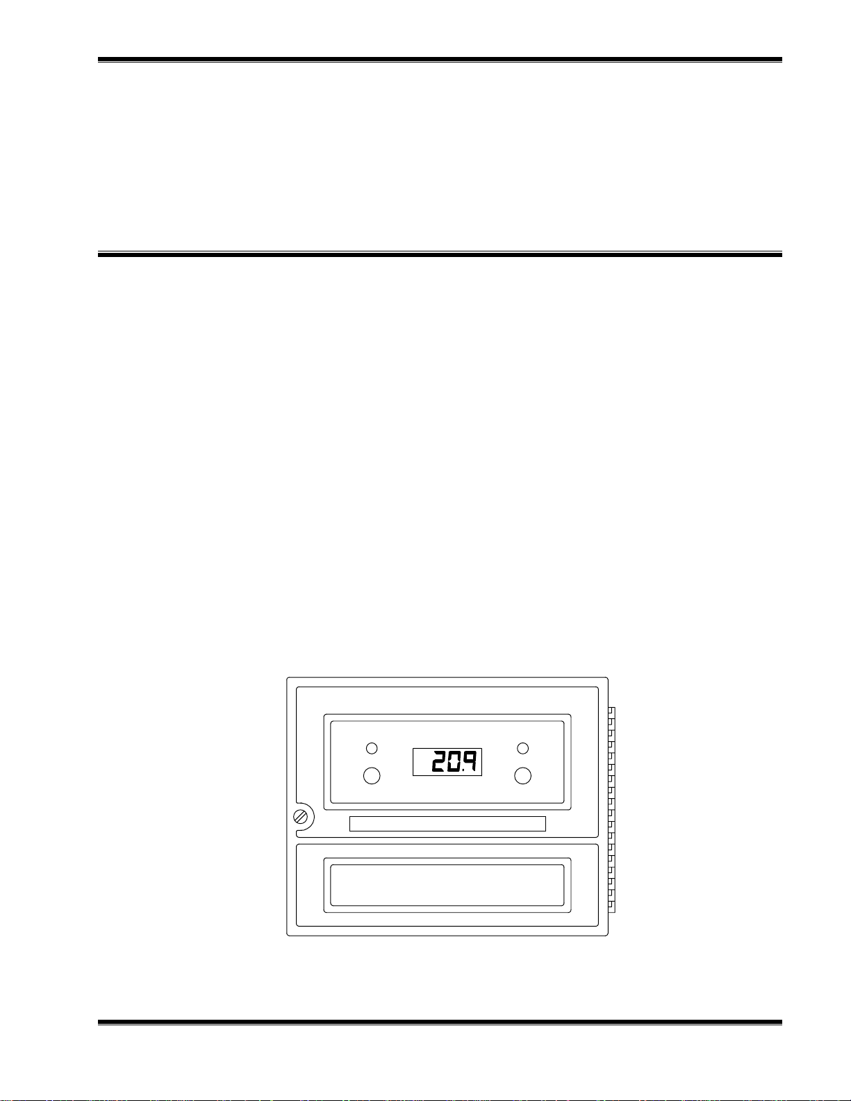
The Model 7003D Oxygen Monitor (Figure 1-1) automatically and continuously
measures the oxygen concentration in gaseous samples. The determination is based
on measurement of the electrical current developed by an amperometric sensor in
contact with the sample.
The monitor provides direct readout of concentration in % by volume. Alarms and a
potentiometric output are provided as standard. The fullscale range of the alarms and
the potentiometric output are each independently selectable. Thus, the range of the
potentiometric output may be changed without the need to readjust alarm setpoints.
The Model 7003D is used with a sensor which is housed in a submersion assembly or
flow assembly and is connected to the monitor by a multi-conductor shielded cable.
1.1 OXYGEN MONITOR
The oxygen monitor conditions the sensor output signal to provide direct readout of
oxygen in % by volume. It also contains current-measuring circuitry, operating
controls, digital display, alarms, and signal outputs provisions.
LOW
SET PT
Model 7003D Oxygen Monitor
IGURE
F
748054-K Rosemount Analytical October 2000
1-1. M
ODEL
7003D O
XYGEN MONITOR
LOW
%
SET PT
Model 7003D Oxygen Monitor
1
Page 18

NTRODUCTION
I
The monitor is designed for panel mounting. Accessory Pipe Mounting Kit permits the
oxygen monitor to be mounted on a vertical or horizontal pipe. Accessory Wall
Mounting Kit permits wall (surface) mounting. An optional air purge kit is designed to
meet requirements for NFPA-496 Type Z air purge (see specifications) .
An accessory Isolated Current Output Board provides a field-selectable 0 to 20 mA, or
4 to 20 mA isolated current output.
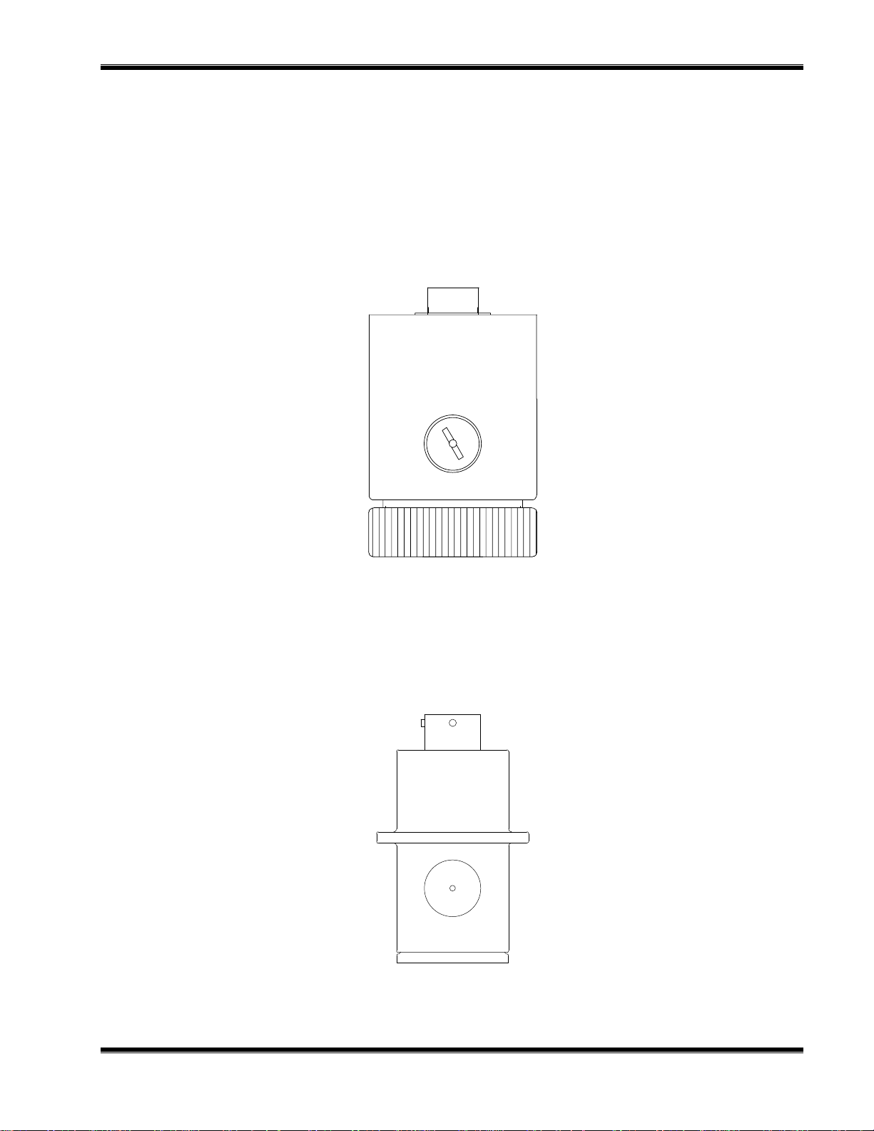
1.2 SENSORS
Rosemount Analytical offers rechargeable and disposable oxygen sensors which can
be used with the Model 7003D. See Figures 1-2 and 1-3. These sensors are supplied
alone or in kits: Submersion, in-line flow, and fast response.. Sensors are available
constructed of polypropylene or Ryton. See Sections 2.4 - Sensors, Rechargeable,
2.5 - Sensors - Non-Rechargeable and 7.3 - Sensors, Replacement Parts for
additional information.
ECHARGEABLE
R
The fast-response flow assembly allows minimum volume gas flow that permits
mounting the sensor in a flowing gas stream. Sample is supplied at slightly above
atmospheric pressure, flows through the assembly and discharges to atmospheric
pressure. Internal volume of the assembly is low to minimize system response time.
ECHARGEABLE
R
The in-line pressure compensated flow assembly permits mounting the sensor in a
variable pressure gas stream at pressures up to 50 psig (345 kPa). The typical
application is in-line monitoring with the flow assembly connected directly into the
process stream pipeline. An alternative application involves discharge to atmospheric
pressure where discharge rates are high.
ECHARGEABLE
R
The submersion assembly permits placing the sensor at depth, in an open or closed
vessel, at a maximum pressure of 50 psig (345 kPa). The submersion assembly
provides a convenient means of mounting the sensor, and also affords protection for
the sensor cable connection a feature particularly desirable in high humidity
environments.
AST-RESPONSE FLOW
- F
- IN-L
- S
INE FLOW
UBMERSION ASSEMBLY
NON-R
The in-line flow assembly permits mounting the sensor in a flowing gas stream. Also
included is a universal mounting bracket and a cable assembly for connecting the
disposable oxygen sensor to the monitor.
2
ECHARGEABLE
- IN-L
INE FLOW
October 2000 Rosemount Analytical 748054-KModel 7003D Oxygen Monitor
Page 19
NTRODUCTION
I
NON-R
ECHARGEABLE
UBMERSION
- S
The submersion assembly adapts the oxygen sensor so that it may be inserted
through the wall of a vessel or pipe to monitor the oxygen concentration existing in the
vessel or pipe.
IGURE
F
IGURE
F
1-2. R
ECHARGEABLE SENSOR
1-3. NON-R
ECHARGEABLE SENSOR
748054-K Rosemount Analytical October 2000
Model 7003D Oxygen Monitor
3
Page 20

NTRODUCTION
I
NOTES
4
October 2000 Rosemount Analytical 748054-KModel 7003D Oxygen Monitor
Page 21

S
TARTUP AND CALIBRATION
3
2.1 UNPACKING AND FACILITY PREPARATION
Carefully examine the shipping carton and contents for signs of damage. Immediately
notify the shipping carrier if the carton or contents is damaged. Retain the carton and
packing material until all components associated with the Model 7003D Oxygen
Monitor are operational.
Outline and mounting dimensions for the oxygen monitor are given in the outline and
mounting drawing 622617.
2.2 LOCATION AND MOUNTING
Mount the sensor in an environment within the permissible range of 32°F to 110°F
(0°C to 44°C) The sensor is supplied, as ordered, in a kit that includes a submersion
assembly or flow chamber.
Sensor and amplifier are interconnected by a multi-conductor shielded cable. It is
supplied in the standard 10 foot length, or in any length specified by customer, up to
1000 feet (305 m). See Section 7.
The oxygen monitor is designed to meet NEMA-4X requirements, and may be
mounted outdoors Permissible ambient temperature range is -20°F to +122°F (-29°C
to +50°C).
Panel mount the amplifier, or use the accessory wall mount kit or accessory pipe
mount kit as desired.
748054-K Rosemount Analytical October 2000
Model 7003D Oxygen Monitor
5
Page 22

NSTALLATION
I
2.3 ELECTRICAL CONNECTIONS
WARNING: ELECTRICAL SHOCK HAZARD
Do not operate without doors and internal circuit panel secure. Servicing
requires access to live parts which can cause death or serious injury. Refer
servicing to qualified personnel.
For safety and proper performance this instrument must be connected to a
properly grounded three-wire source of power. Electrical installation must be
made in accordance with any applicable national or local codes.
2.3.1 L
INE POWER CONNECTION
The Model 7003D provides switch-selectable operation on either 107 VAC to 127 VAC
or 214 VAC to 254 VAC, 50/60 Hz.
Electrical power is supplied to the monitor via a customer-supplied three-conductor
cable, type SJT. minimum wire size 18 AWG. Route power cable through conduit
and into appropriate opening in monitor enclosure. Connect power cable leads to
terminal strip TB5 on the power supply board, as shown in Figure 2-1 and drawing
622228.
OLTAGE SELECT
V
1. Open the monitor door.
2. Loosen the retainer screw which holds the display board and pivot the display
board to access the power supply board.
3. Verify that the line voltage selector switch S1 is set to indicate the nominal line
voltage: either 115 or 230 (Figure 2-1).
2.3.2 S
YSTEM GROUNDING CONNECTION
A ground terminal (TB5-GND) is provided on the power supply board. Refer to Figure
2-1. This terminal must be connected, via the ground lead of the three-conductor
power cable to a good earth ground.
6
October 2000 Rosemount Analytical 748054-KModel 7003D Oxygen Monitor
Page 23

NSTALLATION
I
IGURE
F
Isolated V/I Board
(Option)
(see Figure 3-2)
Recorder
TB3
Sensor
TB2
2-1. P
OWER SUPPLY BOARD
R
1
R4
R3
R8
R9
POWER SUPPLY BOARD 622537
J1
R5 R6
U2
C2
U3
U6
C4
O
G
I
C5
CR2
1 2 3 4
I G O
TB1
30K
THERM
TB2
Current Output
TB3
C1
U1 J1
CR
C3
U4
I
G
O
U5
3K/10K
THERM
SHLD
CATH
AM
TB3
CR2
U5
O
G
I
U1
U3
O
G
I
O
O
G
I
I
G
U2 U4
SHIELD
+VOLTAGE OUT
-VOLTAGE OUT
+CURRENT OUT
-CURRENT OUT
CR3
CR4
CR1
C2 C1
O
I
K2
G
C3
T1
Voltage Select Switch
F1
K1
TB4
NO
COM
NC
NO
COM
NC
ALARM
ALARM
TB5
GND
NEUTRAL/L2
HOT/L1
S1
S1
AC Power
TB5
2.3.3 S
ENSOR CABLE CONNECTION
If a long cable is used, it should be routed to the amplifier through appropriate conduit.
Connect the amplifier end of the cable to terminal strip TB2 on the power supply
board, as shown in Figure 2-1 and drawing 622228.
Connect the cable to the sensor when installation of the sensor is complete.
2.3.4 O
UTPUT CABLE CONNECTION
WARNING: ELECTRICAL SHOCK HAZARD
To avoid shock hazard and AC pickup, do not route potentiometric output or
current output cables through the same conduit as power cable or alarm output
cable.
If a recorder, controller, or other output device is used, connect it via number 22 or
number 24 AWG two-conductor shielded cable. Route the output cable through
conduit to the oxygen monitor, and into the case through the appropriate opening
shown in drawing 622617.
748054-K Rosemount Analytical October 2000
Model 7003D Oxygen Monitor
7
Page 24

NSTALLATION
I
OTENTIOMETRIC OUTPUT
P
1. Connect leads of shielded recorder cable to VOLTOUT + and VOLTOUT -
terminals of TB3 on power supply board (Figure 2-1). Connect shield to SHD
terminal.
2. Connect other end of output cable to appropriate terminals of recorder or other
potentiometric device.
a. For devices with spans of 0 to 1.0 to 5, or 0 to 10 volts connect cable directly to
input terminals of the device, making sure polarity is correct.
b. For devices with intermediate spans. i.e., between the specified values,
connect cable to device via a suitable external voltage divider. as shown in
Figure 2-2.
SOLATED CURRENT OUTPUT ACCESSORY
I
1. Verify that the current output board (Isolated V/I Board) is properly mounted on the
power supply board in connector J2. See Figure 2-1. If originally ordered with the
oxygen monitor, the board is factory installed.
2. Connect leads of shielded cable to CURRENT OUT + and CURRENT OUT -
terminals of TB3 on power supply board. Connect shield to SHD terminal.
3. Connect other end of output cable to input terminals of recorder or other
current-actuated device, making sure polarity is correct. If two or more
current-actuated devices are used, they must be connected in series. Refer to
Figure 2-2.
Note
Total resistance of all output devices and associated interconnection cable
must not exceed 600 ohms.
4. Since neither the CUROUT + nor CUROUT - output terminal is grounded, the
current loop should be grounded at some point within the circuit. The ground point
should be chosen to minimize noise or other undesirable interactions.
8
October 2000 Rosemount Analytical 748054-KModel 7003D Oxygen Monitor
Page 25

NSTALLATION
I
IGURE
F
2-2. C
S
7003D
Monitor
Position of Recorder Output
Selector Plug
10 mV 1K Ohm
100 mV 10K Ohm
1 V 100K Ohm
5 V 2K Ohm
Voltage Divider
(Customer Suppli ed)
Mini mum P ermissibl e Re sist an ce for
R1 + R2
Potentiometric
Recorder
Input
Terminals
(Verify polarit y
is correct)
ONNECTIONS FOR POTENTIOMETRIC RECORDER WITH NON-STANDARD
PAN
IGURE
F
2-3. T
S
7003D
Monitor
mA
+
-
+
-
+
-
+
-
Recorder
Controller
Remote
Indicator
YPICAL EXAMPLE OF OXYGEN MONITOR CONNECTED IN SERIES WITH
EVERAL CURRENT ACTUATED DEVICES
748054-K Rosemount Analytical October 2000
Model 7003D Oxygen Monitor
9
Page 26

NSTALLATION
I
2.3.5 O
UTPUT CONNECTIONS FOR ALARMS
LARM OUTPUT CONNECTIONS
A
The alarm output provides two sets of relay contacts for actuation of alarm and/or
process-control functions. Leads from the customer-supplied external alarm system
connect to terminal block TB4 on the power supply board. See Figure 2-1 and
drawing 622228.
If the alarm contacts are connected to any device that produces radio frequency
interference (RFI), it should be arc-suppressed. Accessory Arc Suppressor is
recommended. When possible, the oxygen monitor should operate on a different AC
power source, to minimize RFI.
LARM RELAY CHARACTERISTICS
A
The HI ALARM and LO ALARM outputs are provided by two identical single-pole
double-throw relays. Relay contacts are rated at (resistive load):
3 A, 250 VAC
3 A, 30 VDC
Removal of AC power from the analyzer, as in a power failure, de-energizes both
relays.
HI ALARM R
ELAY
The HI ALARM relay coil is energized when the display moves upscale through the
value that corresponds to the setpoint plus deadband. This relay coil is de-energized
when display moves downscale through the value that corresponds to setpoint minus
deadband.
LO ALARM R
ELAY
The LO ALARM relay coil is energized when the display moves downscale through the
value that corresponds to setpoint minus deadband. This relay coil is de-energized
when the display moves upscale through the value that corresponds to setpoint plus
deadband.
LARM RESET
A
The HI ALARM and LO ALARM functions both incorporate automatic reset. When the
meter reading goes beyond the pre-selected limits, the corresponding relay is
energized; when the meter reading returns within the acceptable range, the relay is
automatically de-energized.
10
October 2000 Rosemount Analytical 748054-KModel 7003D Oxygen Monitor
Page 27

NSTALLATION
I
AIL SAFE APPLICATIONS
F
By appropriate connection to the double-throw relay contacts, it is possible to obtain
either a contact closure or a contact opening for an energized relay. The
de-energized relay then provides a contact opening or contact closure, respectively. It
is important for failsafe applications that the user understand what circuit conditions
are desired in event of power failure and the resultant relay de-energization. Relay
contacts should then be connected accordingly.
748054-K Rosemount Analytical October 2000
Model 7003D Oxygen Monitor
11
Page 28

NSTALLATION
I
2.4 SENSORS - RECHARGEABLE
This section provides instructions on installation and gas connections of the sensors in
the three available mounting configurations. Refer to Section 2.6 for electrical
connections to sensor. Refer to Section 7 for part numbers of sensors, sensor kits,
and accessories. The sensor is shipped assembled, charged, and ready for use.
2.4.1 I
NSTALLATION OF SENSOR AND FAST-RESPONSE FLOW KIT
The Fast-Response Flow Assembly is used to mount the sensor in a gaseous sample
flow stream. It is used when the sample is supplied at slightly above atmospheric
pressure. Internal volume is low to minimize system response time.
OUNTING FLOW CHAMBER
M
The flow chamber has two .2 diameter clearance holes for mounting screws (screws
supplied by user). See Figure 2-4.
Mount the flow chamber as shown in Figure 2-6. Preferably, mount the flow chamber
so that the sensor is vertical as shown in Figure 2-6A. Horizontal mounting, Figure 26B, is acceptable provided the sample enters the lower port of the chamber and
discharges from the upper port.
NSTALLING SENSOR
I
1. Refer to Figure 2-5. Remove the sensor cap from the sensor. Slide the stainless
steel ring clamp onto the threads for the sensor cap until stops against sensor
body. Replace the sensor cap. The ring clamp is held between the cap and body
of the sensor.
2. Insert the o-ring and cap end of the sensor into the flow chamber.
3. Slide the flow chamber nut down the body of the sensor and tighten onto flow
chamber.
The o-ring between the bottom of the chamber and the sensor cap now effects a seal.
AS CONNECTIONS
G
Sample inlet and outlet connections are 1/8 inch NPT (Figure 2-4). Normally, sample
is supplied to the flow chamber via a customer supplied needle valve which provides
flow adjustment.
RESSURE AND FLOW
P
The flow chamber is designed for discharge at atmospheric pressure. Maximum
recommended flow is 2 liters per minute. Minimum acceptable flow rate depends on
required rate of system response, which is dependent on length of the sample line,
and in some cases, the volume of gas sample that can be wasted.
12
October 2000 Rosemount Analytical 748054-KModel 7003D Oxygen Monitor
Page 29

NSTALLATION
p
p
I
IGURE
F
2-4. R
Ring
Nut
Clam
Sensor Ca
Flow Chamber
Sensor Body
O-Ring
ECHARGEABLE SENSOR WITH FAST RESPONSE FLOW ASSEMBLY
Cable to Oxygen Analyzer
IGURE
F
Ring Clamp
Sample Inlet/Outlet
1/8 NPT
DIMENSIONS
Inch
[mm]
2-5. M
OUNTING RECHARGEABLE SENSOR IN FAST RESPONSE FLOW
SSEMBLY
A
Sensor
Nut
O-Ring
Flow
Chamber
[9]
3.6
[9.1]
1.5
[37]
.4
∅ 3.0
[76]
Mounting Holes (2)
∅.2 THRU
C'BORE ∅ .38 x .25 DP
1.5
[38]
748054-K Rosemount Analytical October 2000
Model 7003D Oxygen Monitor
13
Page 30

NSTALLATION
I
A. Vertical Installation (Preferred)
IGURE
F
2.4.2 I
Vent to
Atmosphere
B. Horizontal Installation
2-6. T
NSTALLATION OF SENSOR AND IN-LINE FLOW KIT
YPICAL INSTALLATION ORIENTATION OF RECHARGEABLE SENSOR AND
AST RESPONSE FLOW ASSEMBLY
F
Vent to
Atmosphere
Sample In
Sample In
The In-Line Flow Assembly is used to mount the sensor in a variable-pressure
gaseous or liquid sample stream, at pressures up to 50 psig (345 kPa).
The typical application is in-line monitoring, with the flow assembly connected directly
into the process-stream pipeline. An alternative application involves discharge to
atmospheric pressure where hig h di schar g e rates ar e desi red.
Note that the sensor responds to partial pressure of oxygen in the sample. If total
pressure changes, the oxygen r esponds accor ding l y .
For liquid sample streams, it is recommended that the assembly be mounted so the
sensor is in the vertical position, as shown in Figure 2-8. In this orientation the sample
enters the lower port of the assembly and discharges to the upper port. The horizontal
arrangement ensu res that during setup there will be immediate discharge of any gas
in the flow chamber or any entrained gases in the sample stream.
For gaseous sample streams, the assembly may be mounted with the sensor
horizontal, if desired.
14
October 2000 Rosemount Analytical 748054-KModel 7003D Oxygen Monitor
Page 31

NSTALLATION
I
OUNTING FLOW CHAMBER
M
Outline and mounting dimensions are given in Figure 2-7. The flow chamber has two
.22 diameter clearance holes for mounting screws (screws supplied by user). The
sample inlet and sample outlet are 1/2 FPT. Mount the flow chamber as shown in
Figure 2-8.
NSTALLING SENSOR
I
1. Remove the clamp and adapter ring from the flow chamber.
2. Insert the sensor (with gland) into the flow chamber.
3. Replace the adapter ring and clamp.
AS CONNECTIONS
G
Sample inlet and sample outlet connections are 1/2 FPT.
RESSURE AND FLOW
P
MAXIMUM PRESSU R E
MAXIMUM FLOW
MINIMUM FLOW
GAS STREAM LIQUID STREAM
50 psig (345 kPa) 50 psig (345 kPa)
2 cfm (60 L/min) 5 gal/min (6 L/min)
dependent on desired response time 1.5 gal/min (6 L/min)
748054-K Rosemount Analytical October 2000
Model 7003D Oxygen Monitor
15
Page 32

NSTALLATION
I
Flow Chamber
Sample Inlet/Outlet
1/2 NPT Female
Gland
Adapter Ring
Clamp
DIMENSIONS
[mm]
Inch
.75
[19]
4.0
[102]
4.5
[127]
Mounting Holes
.219 [6] DIA
3.5
[89]
IGURE
F
IGURE
F
2-7 R
Sample In To drain or process
2-8. P
AND
ECHARGEABLE SENSOR WITH GLAND AND IN-LINE FLOW ASSEMBLY
stream
REFERRED INSTALLATION ORIENTATION OF RECHARGEABLE SENSOR
INE FLOW ASSEMBLY
IN-L
16
October 2000 Rosemount Analytical 748054-KModel 7003D Oxygen Monitor
Page 33

NSTALLATION
I
2.4.3 I
NSTALLATION OF SENSOR AND SUBMERSION KIT
The Submersion Assembly permits placing the sensor at depth in an open or closed
vessel. The Submersion Assembly provides a convenient means of mounting the
sensor, and also affords protection for the sensor cable connection, a feature
particularly desirable in high-humidity environments.
For liquid sample stream, it is recommended that the submersion assembly be
mounted in horizontal position, as shown in Figure 2-10. This arrangement prevents
entrapment on the membrane of gas bubbles which could cause erroneous oxygen
readings.
For installation made during plant construction, a swing-arm piping arrangement
installed in the side of the tank has proved most satisfactory. The sensor cable is led
from the sensor through the supporting pipe. A junction box located in a manhole on
the deck beside the aeration vessel may be included optionally to facilitate pulling of
the cable. Permanently installed conduit carries the sensor cable to the amplifier,
which may be located in any convenient building or protective enclosure. Figures 2-11
and 2-12 illustrate typical installations.
OUNTING IN GASEOUS SAMPLE STREAM
M
For gaseous samples, the submersion assembly may be oriented horizontally or
vertically.
PERATING PRESSURE
O
Maximum permissible operating pressure is 50 psig (345 kPa), equivalent to a water
depth of approximately 100 feet (approximately 30 m).
IQUID SAMPLE FLOW
L
For liquid sample streams, velocity of the liquid past the sensor tip must be at least 1.5
feet per second (45 cm/sec) for flow-independent oxygen readout.
OUNTING CHAMBER
M
The chamber is mounted to 3/4 inch pipe (customer supplied), which the sensor cable
is fed through. See Figures 2-9 and 2-10.
NSTALLING SENSOR
I
1. Remove the clamp and adapter ring from the flow chamber.
2. Insert the sensor (with gland) into the flow chamber.
3. Replace the adapter ring and clamp.
748054-K Rosemount Analytical October 2000
Model 7003D Oxygen Monitor
17
Page 34

NSTALLATION
A
g
A
y
I
ENSOR CABLE
S
In a permanent installation, the sensor cable is normally routed through a customersupplied conduit, which screws into the 3/4 inch NPT connection on the submersion
assembly.
In applications where the sensor cable is not housed in conduit, the cable connector
accessory (PN 856832) may be used. This separately ordered item provides
watertight sealing to prevent leakage around the cable. The connector is constructed
of aluminum and includes a inner sealing grommet and compression nut.
IGURE
F
Submersion
ssembl
3.4
[86]
2-9. R
Chamber
Ring Clamp
2.0
[51]
dapter Rin
1.9
[48]
7.4
[187]
Aluminum Cable Connector
(Accessory)
2.9
[73]
3/4 - 14 NPT
ECHARGEABLE SENSOR WITH SUBMERSION ASSEMBLY
Sensor Cable to Oxygen Monitor
Customer supplied 3/4 inch pipe
Submersion Assembly horizontal
1. Preferred orientation in liquid sample stream.
2. Orientation in gaseous sample may be either horizontal or vertical.
IGURE
F
2-10. T
18
YPICAL INSTALLATION OF RECHARGEABLE SENSOR AND
UBMERSION ASSEMBLY
S
October 2000 Rosemount Analytical 748054-KModel 7003D Oxygen Monitor
Internal Sensor membrane
vertical
Page 35

Manhole
Cable to Oxygen Monitor
Diffuser
NSTALLATION
I
Submersion Assembly
Pipe and fittings to s ui t installation
IGURE
F
Pipe and fittings to s ui t installation
2-11. T
YPICAL PERMANENT INSTALLATION OF RECHARGEABLE SENSOR
WITH
S
Handrail
Chain to Deck
Level
UBMERSION ASSEMBLY DURING PLANT CONSTRUCTION
Capped pipe clamped to handrail
Cable to Oxygen Monitor
Diffuser
Chain to
Handrail
Union (loose to act as swivel)
Submersion Assembly
IGURE
F
748054-K Rosemount Analytical October 2000
2-12. T
YPICAL INSTALLATION OF SENSOR/SUBMERSION ASSEMBLY IN AN
XISTING PLANT
E
Model 7003D Oxygen Monitor
19
Page 36

NSTALLATION
I
2.5 SENSORS - NON-RECHARGEABLE
2.5.1 C
2.5.2 I
ONVERSION OF OXYGEN MONITOR FROM USE WITH RECHARGEABLE
ENSOR TO USE WITH NON-RECHARGEABLE SENSOR
S
The 7003D monitor is shipped from the factory configured for use with a rechargeable
sensor. To convert the instrument for use with a non-rechargeable sensor, a NonRechargeable Sensor Conversion Kit must be installed. The Conversion Kit changes
the gain of the monitor to match the output current available from the nonrechargeable sensor. Follow the instructions supplied in the kit.
NSTALLATION OF SENSOR AND IN-LINE FLOW ASSEMBLY
This kit consists of a non-rechargeable oxygen sensor designed for analysis of
gaseous oxygen samples, a flow chamber and associated nut, a universal mounting
bracket, a connecting cable to connect the monitor to the sensor, and appropriate
loose hardware (see Figure 2-13). The PVC flow chamber is designed for use with a
non-rechargeable oxygen sensor when a flowing gas stream with discharge of the
effluent from the flow chamber at atmospheric pressure is being measured. This
requirement means that upstream sample pressure reduction must be performed on
the process sample from a pressurized source before it is presented to the flow
chamber for analysis by the sensor. Sample input flow rate should be selected in the
range of 50 to 100 cc/min and care must be taken with downstream pressure drops to
prevent back pressurization of the sensor.
OUNTING THE FLOW CHAMBER
M
Refer to Figure 2-15. The preferred mounting configuration of the sensor is with the
electrical connector at the top of the flow chamber/sensor assembly. Operation in the
horizontal plane is also possible. To facilitate mounting the flow chamber to a bench
surface, wall or pipe, employ the universal mounting bracket included as part of the kit.
The flow chamber has one port which should be capped off with the fitting cap
supplied in the kit. The port to be capped is determined by the user, depending on the
particular application.
NSTALLING THE SENSOR
I
The sensor is inserted into the flow chamber to form a face seal on the front of the
sensor with the O-ring present in the bottom of the flow chamber. The nut is then
placed over the connector end of the sensor and tightened hand tight to form a seal
on the face of the sensor.
AS CONNECTIONS
G
Sample inlet and outlet connections are 1/8-inch NPT. Normally, sample is supplied
at slightly above ambient pressure by use of a customer supplied needle valve which
provides the necessary pressure and flow adjustment to the desired 50 to 100 cc/min
flow rate level.
20
October 2000 Rosemount Analytical 748054-KModel 7003D Oxygen Monitor
Page 37

NSTALLATION
I
2.5.3 I
NSTALLATION OF SENSOR WITH SUBMERSION ASSEMBLY
This kit consists of a non-rechargeable oxygen sensor for gas phase oxygen
measurements, a head space submersion assembly, and assorted required loose
hardware (see Figure 2-15). It is intended for use when the gas phase sensor is to be
inserted through a vessel wall as in the monitoring of a process vessel head space or
when a large diameter process is being monitored directly by insertion of the sensor
through the pipe.
OUNTING THE SUBMERSION ASSEMBLY
M
Refer to Figure 2-15. The sensor installs in the submersion assembly by placing the
doughnut shaped thin rubber gasket on the connector side of flange of the oxygen
sensor by gently slipping it over the sensor body and then connecting the cable to the
cable sensor using the mating connectors. The end of the cable emerging from the
threaded portion of the submersion assembly should then be gently pulled to seat the
sensor within the receiving cavity of the submersion assembly. At this point, the cap
should be placed over the front end of the submersion assembly and then screwed
down snugly. At this point the blue silicone rubber plug has moved with the cable and
is now no longer seated in the threaded portion of the submersion assembly. Hold the
cable securely and move the plug back into the submersion assembly until it is firmly
seated.
The submersion assembly is now ready to be connected to the 3/4-inch pipe in a
manner dictated by the local installation requirements. See Figure 2-16.
ENSOR CABLE
S
In permanent installations the sensor cable is normally routed through a customer
supplied conduit, which screws into the 3/4-inch NPT connection at the end of the
submersion assembly.
PERATING PRESSURE
O
Maximum operating pressure is 50 psig (345 kPa).
748054-K Rosemount Analytical October 2000
Model 7003D Oxygen Monitor
21
Page 38

NSTALLATION
I
Cable
Nut
Fitting, Plug
1/8MPT SS
Flow Chamber
2.1
[54]
10-32 x 1/2" DP
2 Places
2.5
[64]
Fitting (2 ea.)
Male Connector
1/8T - 1/8MPT SS
O-Ring
Bracket Mounting
Hardware (2 ea.):
Screw 10-32 x 5/8
Lock Washer No. 10
Flat Washer No. 10
4.8
[122]
2.6
[67]
3.8
[97]
5.2
[133]
IGURE
F
22
.5
[13]
2 Holes
2-13. D
WITH
.2 [5] DIA
.7
[18]
.5
[12]
.2
[5]
.1
[2]
1.1
[28]
.3
[8]
.7
[17]
IMENSIONS AND COMPONENTS OF NON-RECHARGEABLE SENSOR
INE FLOW KIT
IN-L
October 2000 Rosemount Analytical 748054-KModel 7003D Oxygen Monitor
Page 39

p
LIQUID GAS
NSTALLATION
I
To
Drain
or
Process
IGURE
F
Preferred orientation
of In-Line Flow
Assembly
2-14. T
INE FLOW KIT
L
Grommet/Plug
ter
Ada
Sample
Sample
In
To
Drain
or
Process
Preferred orientation
of In-Line Flow
Assembly
YPICAL INSTALLATION OF NON-RECHARGEABLE SENSOR WITH IN
2.0
[51]
1-11 1/2NPT
In
-
Cable
5.7
[146]
Nut
Gasket
1.0
[25] 2.3
[57]
IGURE
F
748054-K Rosemount Analytical October 2000
2-15. D
IMENSIONS AND COMPONENTS OF NON-RECHARGEABLE SENSOR
WITH
UBMERSION KIT
S
Model 7003D Oxygen Monitor
23
Page 40

NSTALLATION
to Handra
s
)
to Handra
s
)
I
A. INSTALLATION DURING PLANT CONSTRUCTION
Manhole
Manhole
Cable to Oxygen Monitor
Cable to Oxygen Monitor
Diffuser
Diffuser
Chain to
Chain to
Deck Level
Deck Level
Pipe and fittings to suit
Pipe and fittings to suit
installation.
installation.
B. INSTALLATION IN EXISTING PLANT
Cable to Oxygen Monitor
Handrail
Handrail
Pipe and fittings to suit
Pipe and fittings to suit
installation.
installation.
Cable to Oxygen Monitor
Diffuser
Diffuser
Sensor/Submersion Assembly
Sensor/Submersion Assembly
Capped Pipe Clamped
Capped Pipe Clamped
il
il
Union (loose to act as
Union (loose to act as
wival
wival
Chain to
Chain to
Deck Level
Deck Level
Sensor/Submersion Assembly
Sensor/Submersion Assembly
IGURE
F
24
2-16. T
UBMERSION KIT
S
YPICAL INSTALLATION OF NON-RECHARGEABLE SENSOR WITH
October 2000 Rosemount Analytical 748054-KModel 7003D Oxygen Monitor
Page 41

S
TARTUP AND CALIBRATION
3
Prior to startup and calibration, familiarization with Figure 3-1 is recommended. This
figure gives locations and brief descriptions of operating controls and adjustments on
the display board.
3.1 SYSTEM STARTUP
After completing the installation per Section 2, proceed as follows:
1. On the Display Board (refer to diagram inside door and Figure 3-1):
a. Select potentiometric output fullscale range by placing output/alarm switch S3
in ON position. Choices are 0 to 25%, 0 to 10%, 0 to 5%, and 0 to 1%
oxygen.
b. Select potentiometric output fullscale voltage by placing output volts switch S2
in ON position. Choices are 0 to 1, 0 to 5, and 0 to 10 volts, fullscale.
c. Set alarm switches S4 and S5 to OFF position, to avoid activating either alarm
before setpoints and deadbands have been adjusted (Section 3.3).
2. Turn on line power.
3. W ait for a suitably stable reading on the digital display. The time required by the
user for stabilization of the sensor to levels of perf ormance where the stability of
the sensor meets the requirement of a particular user is defined as the
equilibration time, that is, the time when the sensor is said to be equilibrated.
Normal operation of the analyzer involves adjustments of only the front-panel
controls: ZERO and SPAN, and RANGE Switch, if provided. See Figure 1-1.
3.2 CALIBRATION
ENSOR
S
Each sensor has an individual residual current that must be zeroed out by
adjustment of R52 on the Display Board. The sensor is purged with nitrogen gas
until a stable reading is obtained. Adjust R52 for a zero reading. This adjustment is
required each time a new or recharged sensor is installed.
After the sensor has stabilized, the instrument is ready for calibration. Perform the
procedure in Section 3.2.1 or 3.2.2, as appropriate.
ESIDUAL CURRENT ZEROING
- R
748054-K Rosemount Analytical October 2000
Model 7003D Oxygen Monitor
25
Page 42

TARTUP AND CALIBRATION
S
3.2.1 C
ALIBRATION WITH AIR
Calibration with dry air is the preferred method, applicable in all situations. The most
convenient source of dry air, when available, is a cylinder of compressed air. It is
important, however, to know the actual oxygen content of the cylinder. Cylinder
compressed air is frequently a prepared blend of O2 and N2, and is not necessarily
labeled as such. U.S. Government standards require only that cylinders labeled
"air" contain between 19% and 23% oxygen.
To determine oxygen content, request an analysis when purchasing the cylinder air.
Another way to determine oxygen content is to pass ambient outdoor air through an
efficient drier on the way to the analyzer, preferably using a diaphragm-type pump.
The concentration of oxygen will then be very close to 21%.
1. On the Display Board, set RANGE switch S7 at 25%, expose sensor to suitable
dry air at ambient atmospheric pressure.
2. Change RANGE switch to CAL position, wait for display reading to stabilize.
Then adjust CAL control (disregard decimal point) to bring display reading to:
760 X % O2 in sample
20.95
In most situations. ambient air may be used in place of the recommended dry air.
Only in instances where temperature and relative humidity are high will significant
errors be introduced through the use of ambient air. At a near-sea-level barometric
pressure, errors are less than 2% for relative humidity under 40% and temperatures
below 95°F (35°C). At 60% relative humidity, ambient air temperatures as high as
82°F (27.8°C) produce a maximum error of 2%. As a rule-of-thumb. dry air should
be used for calibration where ambient temperature exceeds 80°F (26.7°C) and/or
relative humidity exceeds 60%. For calibration with ambient air, the procedure is the
same, except that the sensor is exposed to ambient air instead of dry air.
3.2.2 C
ALIBRATION WITH SPAN GAS
1. Set RANGE switch S7 to 25% or 19.99%, depending upon concentration of span
gas, and expose sensor to span gas, exhausting to ambient pressure.
2. W ait for reading to stabilize, then adjust CAL control to bring display reading to
known concentration of span gas.
3.3 SELECTION OF ALARM RANGE, SETPOINT, AND
DEADBANDS
1. Select alarm fullscale range by placing one slide of output/alarm switch S3 in ON
position. Choices are 0 to 25%. 0 to 10%, 0 to 5% and 0 to 1% oxygen. Refer to
diagram on inside of door.
2. The HI ALARM and LO ALARM setpoint potentiometers are adjustable from 0%
to 100% of the fullscale span. The potentiometers are graduated from 0 to 100.
26
October 2000 Rosemount Analytical 748054-KModel 7003D Oxygen Monitor
Page 43

TARTUP AND CALIBRATION
S
Required potentiometer setting for either setpoint adjustment is determined from
the equation:
required potentiometer setting = desired alarm reading x 100 fullscale span
EXAMPLE:
Alarm range, 0 to 25%; desired Hi Alarm setpoint, 20%; desired Lo Alarm
setpoint, 15%
20
required Hi ALARM setting = x 100 = 80
25
15
required LO ALARM setting = x 100 = 60
25
3. Select the desired deadband. The HI ALARM and LO ALARM deadband
potentiometers are adjustable from 1% of fullscale (counterclockwise limit) to
20% of fullscale (clockwise limit). Deadband is essentially symmetrical with
respect to the setpoint.
4. When setpoints and deadbands have been selected, set alarm switches S4 and
SS to the AUTO position, to activate the alarms.
5. To test external alarm devices, temporarily set alarm switch S4 or S5 in the ON
position. The associated alarm is then unconditionally on.
748054-K Rosemount Analytical October 2000
Model 7003D Oxygen Monitor
27
Page 44

TARTUP AND CALIBRATION
A
S
19.99 25 CAL
LOW ALARM
INDICATOR LED
CR1
LOW ALARM
SETPOINT ADJUST
R43
LOW ALARM
DEADBAND ADJUST
R44
SENSOR CONVERSION
HEADER
J5
RANGE SWITCH S7
CAL CONTROL R14
AMPLIFIER ZERO R46
DISPLAY SPAN R24
RESIDUAL ZERO CONTROL R52
HIGH ALARM
INDICATOR LED
CR2
HIGH ALARM
SETPOINT ADJUST
R40
HIGH ALARM
DEADBAND ADJUST
R41
AUTO OFF ON
LOW ALARM SWITCH
S4
IGURE
F
3-1. D
OUTPUT VOLTAGE
SWITCH S2
OUTPUT/ALARM
SWITCH S3
ISPLAY BOARD
S2
OFF ON
S3
OFF ON
E OUT
LARM
AUTO OFF ON
HIGH ALARM
SWITCH S 5
28
October 2000 Rosemount Analytical 748054-KModel 7003D Oxygen Monitor
Page 45

TARTUP AND CALIBRATION
S
3.4 CURRENT OUTPUT RANGE
Select 0 to 20 or 4 to 20 milliamperes to be minimum current for isolated current
output (if present).
1. On the Display Board (Figure 3-1), set RANGE switch S7 to CAL position.
2. With power OFF, disconnect anode and cathode leads from terminal strip TB2 on
the Power Supply Board (Figure 2-1). Secure the leads so that they will not
contact any board or component.
3. Turn power ON. On the Display Board (Figure 3-1), adjust residual ZERO control
R52 until potentiometric output device indicates 0 volt.
4. On the Isolated Current Output Board, adjust ZERO control R1 (Figure 3-2) so
that current output device indicates the low range-limit desired for the output
range: 0 milliamperes or 4 milliamperes.
5. Turn power OFF. If sensor is rechargeable, connect a 10K ohm resistor between
the anode and the cathode terminals on the Power Supply Board terminal strip
TB2 (Figure 2-1). If sensor is non-rechargeable, connect a 320K ohm resistor
across TB2. This resistor permits the polarizing voltage supply to provide a small
current that simulates the sensor output signal.
6. Turn power ON. On front panel controls, adjust CAL clockwise to produce a
fullscale reading on the potentiometric output device.
7. On the Isolated Current Output Board (Figure 3-2), adjust SPAN control R2 for
reading of 20 milliamps on current output device.
ZERO
R1
R
1
SPAN
R2
R3
R8
R4
R
2
R5 R6
R9
CR2
U6
O
G
I
1 2 3 4
U2
C2
U3
C4
I G O
C1
U1 J1
CR
C3
U4
I
G
O
U5
IGURE
F
748054-K Rosemount Analytical October 2000
3-2. I
SOLATED CURRENT OUTPUT BOARD
Model 7003D Oxygen Monitor
29
Page 46

TARTUP AND CALIBRATION
S
NOTES
30
October 2000 Rosemount Analytical 748054-KModel 7003D Oxygen Monitor
Page 47

O
PERATION
4
4.1 ROUTINE OPERATION
After startup and calibration (Section 3) the monitor will automatically and
continuously indicate the oxygen concentration of the sample.
If potentiometric output or alarms are used on the 0% to 1% oxygen range after
calibration at 20.95% oxygen, an appropriate interval is needed to permit the sensor
to equilibrate to a low concentration of oxygen. The time required for equilibration
depends upon how long the sensor was operated at the higher oxygen level. Thus, a
sensor which has been in operation on air for 24 hours prior to calibration will
typically show a reading of 0.05% oxygen, or less within one hour after exposure to
pure nitrogen. This reading will decrease to 0.01% or so within the next few hours.
Inability to obtain a low-level oxygen reading in a gas of known low-level oxygen
content usually indicates a leak in the sample system. To check this possibility,
increase sample flow rate, block off the flow of gas into and out of the flow chamber,
and note the response of the oxygen monitor. An increase in reading, with time,
indicates a leak in the system. If there is no leak in the system, another possibility is
that a rechargeable sensor should be rejuvenated or that a disposable sensor should
be replaced. The procedure for sensor rejuvenation, which is outlined in Section Six,
must be followed carefully if satisfactory results are to be achieved.
4.2 RECOMMENDED CALIBRATION FREQUENCY
For the first few days of operation the instrument should be calibrated daily to
compensate for initial stabilization of the membrane in the sensor.
After the sensor has stabilized, an instrument in continuous operation should be
calibrated at least once a week until the appropriate calibration interval is
determined. A log of periodic calibrations helps establish desired calibration intervals
for given applications.
4.3 FREQUENCY OF SENSOR RECHARGING
Nominal useful life of a sensor charge is approximately three to six months; after this
time, the sensor should be removed from the installation and recharged. Refer to
Section 6.1.1. Physical damage to the membrane is the most frequent cause of
748054-K Rosemount Analytical October 2000
Model 7003D Oxygen Monitor
31
Page 48

PERATION
O
failure for service periods less than three months. Proper handling and installation of
the sensor into the sample system are essential.
The service life of a disposable 0xygen sensor is application-dependent and no
rejuvenation or recharging is possible. It is difficult to determine the prospective shelf
life of the disposable oxygen sensor, since no time related failure mechanisms are
apparent at this time.
32
October 2000 Rosemount Analytical 748054-KModel 7003D Oxygen Monitor
Page 49

T
HEORY
5
The Model 7003D Oxygen Monitor system consists of an amperometric oxygen
sensor and an amplifier unit interconnected by a multi-conductor shielded cable. The
sensor responds to the partial pressure of oxygen. The amplifier conditions the
sensor signal, providing a readout of oxygen in percent by volume.
The following Sections detail the major principles of operation. Section 5.2 describes
variables that influence the oxygen measurement.
5.1 ELECTROCHEMICAL THEORY
With the sensor placed in the process stream, a voltage is applied across the
cathode and anode (see Figure 5-1). Oxygen in the process stream diffuses through
the membrane and is reduced at the cathode. The reduction of oxygen results in a
current flow proportional to the partial pressure of oxygen in the sample.
When oxygen is not present, no electrical current flows in the sensor. When oxygen
is present, electrical current flows in the sensor according to the characteristic curve
for the particular potential applied to the electrodes. The magnitude of the current
depends upon the partial pressure of the dissolved oxygen in the sample.
THERMISTOR
ELECTROLYTE
CAP
O-RINGS
MEMBRANE
IGURE
F
748054-K Rosemount Analytical October 2000
5-1. R
ECHARGEABLE OXYGEN SENSOR
CATHODE
CABLE
CONNECTOR
BODY
FILL PORT
ANODE
ECTIONAL VIEW
- S
Model 7003D Oxygen Monitor
33
Page 50

HEORY
T
5.2 VARIABLES INFLUENCING OXYGEN MEASUREMENT
Since the amperometric oxygen sensor responds to the partial pressure of oxygen,
any variable that affects that partial pressure should be taken into account to ensure
accurate measurement in the desired units. The two basic variables involved are
barometric pressure and relative humidity.
Since dry air contains 20.95% oxygen by volume, regardless of barometric pressure,
the partial pressure of oxygen is directly proportional to the total barometric pressure,
according to Dalton's law of partial pressures. Thus for dry air, if the total barometric
pressure is known, the partial pressure of oxygen can be computed. However, the
procedure is valid only for dry air. Humid air has the effect of reducing the partial
pressure of oxygen and the other gases in the air without affecting the total
barometric pressure. Another way of expressing this relationship is by the following
equation:
P (atm) = P (gas)+ P (oxygen) + P (water)
where:
P (atm) = total barometric pressure
P (gas) = partial pressure of all gases other than oxygen and water vapor
P (oxygen) = partial pressure of oxygen
P (water) = partial pressure of water vapor
Thus, for constant barometric pressure, if the humidity in the air is not zero, the
partial pressure of oxygen is less than the value for dry air. For most measurements
taken below 80°F (26.7°C) and below 60% RH, the effect of water vapor may be
ignored.
At a barometric pressure of 760 mm Hg (101 kPa), the partial pressure of oxygen in
dry air is approximately 160 mm Hg (21.1 kPa).
To determine the partial pressure of oxygen in air at various levels of humidity and
barometric pressure. the partial pressure of water is subtracted from the total
barometric pressure: this difference is then multiplied by 20.95%.
EXAMPLE
34
barometric pressure = 740 mm Hg (98.5 kPa)
partial pressure H20 = 20 mm Hg ( 2.7 kPa)
partial pressure O2 = (740-20) x 0.2095 mm Hg = 151 mm Hg (20.1 kPa)
October 2000 Rosemount Analytical 748054-KModel 7003D Oxygen Monitor
Page 51

R
OUTINE SERVICE AND TROUBLESHOOTING
6
Most service and maintenance problems involve the sensor. Failures within the
amplifier unit are less frequent. In system checkout, the recommended procedure is
first to isolate the amplifier from the sensor, then perform a few simple tests to
determine if the amplifier is performing satisfactorily. The sensor can be checked and
then recharged, rejuvenated, or replaced, as necessary.
6.1 RECHARGEABLE SENSORS
Most routine maintenance involves the sensor. Sensor maintenance consists of
periodic recharging and cleaning, or rejuvenating the sensor cathode. The usual
indication that the sensor requires rejuvenation and recharging is that, during
calibration. the correct upscale reading is unobtainable by adjustment of the CAL
control. Normally, the inability to calibrate is preceded by a gradual, day-to-day
reduction in sensor output, with a resultant lower instrument indication. The rate of
reduction increases with the increase in internal resistance of the sensor. Other
indicators of need for rejuvenation may be sluggish response or the presence of an
appreciable residual signal when the sensor is exposed to a zero reference sample.
Note
If sensor is disassembled for inspection, it must be recharged utilizing a
new membrane.
Normally, the sensor should be recharged with fresh electrolyte at three-month
intervals. However, the interval may be extended, depending upon the application in
which the sensor is used. In general, correcting a low output can be accomplished by
recharging with fresh electrolyte, as described in Section 6.1.1. If output still remains
low, or the other symptoms exist, the gold cathode should be rejuvenated as
described in Section 6.1.2.
In event of "spiking," i.e., non-oxygen-related transient response, the accessory Cell
Separator Kit is recommended. Refer to Section 6.1.3.
748054-K Rosemount Analytical October 2000
Model 7003D Oxygen Monitor
35
Page 52

OUTINE SERVICE AND TROUBLESHOOTING
R
6.1.1 R
ECHARGING SENSOR
The sensor must be removed from the process installation and disconnected from
the sensor cable for recharging.
The recharging kit consist of electrolyte, membranes, pressure-compensating rubber
diaphragms, O-rings for the membrane retainer, O-rings for the sensor body, and
washers for the diaphragms.
BREATHER
HOLE
CELL SEPARATOR
(Accessory)
HOLDER
MEMBRANE
CAP
O-RING
CATHODE
DIAPHRAGM
WASHER
DIAPHRAGM
SCREW
O-RING
RETAINER
IGURE
F
6-1. R
ECHARGEING PROCEDURE
R
ECHARGEABLE SENSOR
XPLODED VIEW
- E
For this procedure refer to Figure 6-1.
1. Unscrew knurled cap from end of sensor body. Remove membrane assembly,
consisting of membrane fixed between holder and retainer. Empty all electrolyte
from sensor. Flush sensor with distilled or deionized water to remove all
particulate matter.
2. Place a piece of adhesive tape over the breather hole in the pressure
compensation diaphragm port (not the slotted fill plug).
3. Examine cathode for:
36
a. Staining or uneven coloration. which indicates that the cathode should be
rejuvenated as described in Section 6.1.2.
October 2000 Rosemount Analytical 748054-KModel 7003D Oxygen Monitor
Page 53

OUTINE SERVICE AND TROUBLESHOOTING
R
b. Any deposited material, typically white to gray. present in or around the
grooves in the plastic surrounding the cathode. This must be removed to
ensure best operation. Most of these deposits are water-soluble and may
be removed by a water jet from a squeeze bottle. Any insoluble deposits
in the annular and channel grooves may be removed with a toothpick;
however, care must be used to avoid deforming the grooves.
4. Disassemble the membrane assembly. This consists of a plastic membrane,
a holder, a retainer, and an O-ring. Remove retainer from holder by placing
finger into center hole of holder and pressing fingernail against inner edge
of retainer. Remove and discard the old membrane.
5. Verify that O-ring is properly positioned in associated groove in holder.
6. Holding a single membrane by the edges only, place it across membrane
holder and snap retainer in place. Membrane is now fixed in proper
position, between holder and retainer.
CAUTION: MEMBRANE CONTAMINATION
Never touch center area of membrane with fingers. Membranes are easily
contaminated with foreign substances. Contaminated membranes cause
drifting or erratic readings.
7. Using a sharp razor blade, carefully trim away excess membrane around
edge of membrane assembly. Take care that razor blade does not cut into
edges of membrane assembly.
8. Set sensor body on a flat surface, with cathode facing upward. Verify that
O-ring in groove at end of sensor body is properly positioned around
cathode. Pour the electrolyte over the cathode/central post assembly so that
it runs down into the sensor electrolyte well. Fill the well to a level flush with
the top of the sidewall.
Put the membrane assembly directly onto the cathode so that the face of
the holder (i.e., the part with the larger-diameter central hole) fits against the
O-ring in the end of the sensor body.
The membrane is now in place. It will spread any electrolyte remaining on
the cathode into a thin film that wets the entire surface. The membrane
assembly should now be centered over the cathode.
9. Taking care not to disturb the central orientation of the membrane
assembly, carefully place the cap on the sensor body. Screw the cap on,
fingertight only. Then lay the sensor on its side, with the side port up.
Remove side port screw, rubber pressure-compensating diaphragm, and
washer. Add electrolyte, if necessary, to bring the level into the side port
and then rock the sensor from end to end to remove any air pockets. Add
748054-K Rosemount Analytical October 2000
Model 7003D Oxygen Monitor
37
Page 54

OUTINE SERVICE AND TROUBLESHOOTING
R
electrolyte, if necessary, to bring the level even with the shoulder. With the
side port still facing up, tighten the cap further until it is snug, and the
membrane is stretched taut across the cathode. Any excess electrolyte
displaced from the electrolyte well into the side port may now be removed
by blotting with a tissue.
10. Insert new rubber diaphragm into side port, place new washer over
diaphragm, and secure with side port screw. Do not overtighten screw.
11. Inspect sensor for possible leaks or damage to membrane.
12. Remove the adhesive tape installed in Step 2 from the pressure
compensation port.
Sensor is ready for operation. Connect cable. If sensor does not operate properly
refer to Section 6.3.
If normal operation is not obtained with the specified recharging procedure, perform
rejuvenation, as detailed in Section 6.1.2.
6.1.2 R
EJUVENATING CATHODE
If simple recharging does not correct symptoms of low output, clean and/or
rejuvenate the cathode as follows:
WARNING: CORROSIVE MATERIAL
Concentrated nitric acid is used in the following procedure. This material is
highly corrosive. Avoid contact with skin, eyes, clothing, and precision
instrument parts. Use rubber gloves and eye protection. If body contact
occurs, flush copiously with water and seek medical attention.
1. Disassemble sensor. Remove cap and membrane assembly. Discard the used
electrolyte. Flush the sensor with distilled or deionized water to remove all
particulate material.
2. Over a sink, use a cotton swab to treat the cathode with concentrated reagent
grade nitric acid, obtainable from a laboratory supply house. Submerge the tip of
the swab in the nitric acid. Press the swab against the side of the nitric acid
container to remove excess acid. Swab the cathode area lightly for five minutes.
38
3. Take care to confine the nitric acid to the button area. Only a thin film of nitric
acid should be present on the surface of the cathode during the cleaning
operation. Excessive application may result in the destruction of the epoxy
annulus surrounding the button, with resultant sensor failure.
October 2000 Rosemount Analytical 748054-KModel 7003D Oxygen Monitor
Page 55

OUTINE SERVICE AND TROUBLESHOOTING
R
4. Rinse the button and sensor cavity thoroughly with distilled or deionized water.
Then rinse the sensor with electrolyte by pouring it over the cathode into the
sensor cavity until it is filled. Discard this electrolyte.
5. Recharge the sensor in the normal fashion.
If normal operation is not obtained with the specified rejuvenation procedure, the sensor
is depleted and must be replaced.
6.1.3 C
ELL SEPARATOR KIT
The cell separator is used to eliminate "spiking," i.e., non-oxygen-related transient
response on the analyzer output.
This condition is usually caused by reaction products which slough off the anode and
are transported to the cathode surface, where they are reduced. During reduction,
the anode accepts electrons, resulting in the undesired transient response.
The condition may be corrected by installing a separator disk which mechanically
separates the cathode and anode (see Figure 6-1). The kit contains ten disks.
To install the separator in an oxygen sensor, remove the cap and membrane holder.
pour out the electrolyte, and position the hole in the separator over the cathode post.
Then gently push the separator down into the sensor body until it rests on top of the
anode. Fill the sensor with fresh electrolyte and reassemble in the conventional
manner.
6.2 NON-RECHARGEABLE SENSORS
The non-rechargeable sensor has no user accessible internal parts. No sensor
maintenance is possible other than gentle brushing to remove deposits on the face
of the sensor to restore its sensitivity and response time.
If the performance of the sensor has degraded beyond acceptable limits, it must be
replaced.
6.3 TROUBLESHOOTING
The most frequent fault is a progressive development of insensitivity of the sensor.
During calibration, the CAL control must be turned farther and farther clockwise to
set the meter to the desired calibration value. Finally, after several months of
operation, rotating the CAL control to its clockwise limit fails to bring the meter to the
desired calibration setting.
The cause of this characteristic change is the gradual exhaustion or occlusion of the
sensor. Accordingly, the sensor must be maintained as described in Section 6.
748054-K Rosemount Analytical October 2000
Model 7003D Oxygen Monitor
39
Page 56

OUTINE SERVICE AND TROUBLESHOOTING
R
System problems can be isolated to the sensor or the amplifier by the following
procedure:
1. Disconnect AC power from the instrument.
2. Set alarm switches S4 and S5 (Figure 3-1) to OFF position.
3. On TB2 (Figure 2-1) make following connections:
a. Disconnect all leads of sensor cable.
b. Connect a 10K ohm resistor across the three l0K THMS terminals. This
resistor simulates the resistance of the thermistor at 25°C.
c. If the sensor is rechargeable, connect a 10 K ohm resistor across terminals
marked AN (for anode) and CATH (for cathode). If the sensor is
non-rechargeable, connect a 320 K ohm resistor across the terminals. This
resistor permits the polarizing voltage supply to provide a small current that
simulates the sensor output signal.
4. Set RANGE switch to CAL (Figure 3-1).
5. Rotate CAL control throughout its range to verify that the outputs of the
instrument respond from near zero to above fullscale.
If test yields correct results, amplifier is operational. The fault is in sensor or cable.
Remove 10 K ohm resistors from TB2 and proceed to tests given in Section 6.3.1 or
6.3.2.
If these tests do not yield correct results, contact a factory authorized service
representative.
6.3.1 C
HECKING RECHARGEABLE SENSOR AND CABLE
For convenience, the sensor cable may be regarded as part of the sensor.
Accordingly, electrical checks are made at the terminal ends of the cable,
disconnected from the amplifier at TB2. Verification of electrical integrity of the
sensor is determined by making the following checks with an ohmmeter:
1. Resistance between white and green leads should be 10 ohms +1% at 25°C
(approximately 30 ohms at 0°C, and 4 ohms at 50°C). Readings from white or
green lead to any other lead of the sensor cable should indicate open circuit, or
at least 100M ohms. Readings less than this indicate a shunt resistance path
which produces an error in the measurement.
40
2. T he black and white lead is connected to the grounding shield. Readings from
this lead to any other lead of the sensor cable should be at least 100M ohms.
October 2000 Rosemount Analytical 748054-KModel 7003D Oxygen Monitor
Page 57

OUTINE SERVICE AND TROUBLESHOOTING
R
3. If checks in Steps I or 2 indicate trouble, or if other symptoms indicate the
sensor to be faulty, determine the probable cause by reference to the
appropriate symptom(s) in Table 6-1. This table is a compilation of the most
common sensor problems.
SYMPTOM PROBABLE CAUSE CORRECTIVE ACTION
Hole in sensor membrane Replace membrane
Abnormally high oxygen
readings (unable to calibrate)
Gold cathode loose Replace sensor
Open thermistor Replace sensor
ABLE
T
High internal cell resistance
Abnormally low oxygen
Membrane too loose
readings (unable to calibrate)
Contaminated electrolyte
Thermistor shorted Replace sensor
Membrane loose Replace membrane
Sensor noisy (motion sensitive)
Upscale reading with known
oxygen-free sample
Low electrolyte level Fill properly
Cathode contaminated
2
Gold cathode loose Replace sensor
Slow response (sluggish) Contaminated electrolyte
6-1. R
ECHARGEABLE SENSOR TROUBLESHOOTING GUIDE
Rejuvenate/recharge
sensor
Tighten cap or replace
membrane
2
Clean/recharge sensor
Rejuvenate/recharge
sensor
Rejuvenate/recharge
2
sensor
2
"Contamination" may be the normal accumulation resulting from long-term operation, indicative that the standard cell-
rejuvenation procedure is required.
748054-K Rosemount Analytical October 2000
Model 7003D Oxygen Monitor
41
Page 58

OUTINE SERVICE AND TROUBLESHOOTING
R
6.3.2 C
HECKING NON-RECHARGEABLE SENSOR AND CABLE
To check the cable disconnect it from the monitor and the sensor. The resistance
between any two leads should be at least 100 M ohms. A continuity check on any
lead should produce a reading of less than 15 ohms per thousand feet.
SYMPTOM PROBABLE CAUSE CORRECTIVE ACTION
Abnormally high oxygen readings Hole in sensor membrane Replace sensor
(unable to calibrate) Open thermistor Replace sensor
Cell contaminated Replace sensor
Abnormally low oxygen readings Thermistor shorted Replace sensor
(unable to calibrate) Membrane surface dirty Clean front surface
Adjust sensor zero
Upscale reading with known
oxygen-free sample (greater than
0.1% O2 or equivalent)
Sensor contaminated
control
Check linearity with
standards
Slow response (sluggish) Contaminated electrolyte2Replace sensor
ABLE
T
6-2. NON-R
ECHARGEABLE SENSOR TROUBLESHOOTING GUIDE
42
October 2000 Rosemount Analytical 748054-KModel 7003D Oxygen Monitor
Page 59

R
EPLACEMENT PARTS
7
WARNING: PARTS INTEGRITY
Tampering or unauthorized substitution of components may adversely affect
safety of this product. Use only factory documented components for repair.
7.1 CIRCUIT BOARD REPLACEMENT POLICY
In most situations involving a malfunction of a circuit board, it is more practical to
replace the board than to attempt isolation and replacement of the individual
component, as the cost of test and replacement will exceed the cost of a rebuilt
assembly. As standard policy, rebuilt boards are available on an exchange basis.
Because of the exchange policy covering circuit boards, the following list does not
include individual electronic components. If circumstances necessitate replacement
of an individual component, which can be identified by inspection or from the
schematic diagrams, obtain the replacement component from a local source of
supply.
7.2 REPLACEMENT PARTS
858728 Arc Suppressor
637358 Cell Separator Kit (10 separator disks)
622529 Display Board
777156 Fuse, 1/4 A - 120 VAC (Package of 5)
777360 Fuse, 1/8 A - 240 VAC (Package of 5)
620433 Isolated Current Output Board (Option)
622621 Pipe Mounting Kit
622537 Power Supply Board
193265 Sensor Cable
191748 Sensor Cable 10'
856831 Sensor Cable Connector Accessory
191755 Sensor Recharge Kit (10 recharges)
652117 Wall Mounting Kit
3
Length specified by customer, any length up to 1000'.
748054-K Rosemount Analytical October 2000
3
Model 7003D Oxygen Monitor
43
Page 60

EPLACEMENT PARTS
R
7.3 REPLACEMENT PARTS - SENSORS
7.3.1 R
ENSOR
S
ENSOR KITS (SENSOR NOT INCLUDED
S
ECHARGEABLE SENSORS
:
MATERIAL PART NUMBER
Polypropylene 623371
Polypropylene 623370 (use with Fast Response Kit)
Ryton 190408
Ryton 190409 (use with Fast Response Kit)
):
DESCRIPTION PART NUMBER USE WITH SENSOR
Submersion, Polypropylene 639904 623371
In-Line Flow, Polypropylene 639905 623371
Fast Response, Polypropylene 639906 623370
Submersion, Ryton 646628 190408
In-Line Flow, Ryton 646629 190408
Fast Response, Ryton 646630 190409
ENSOR KITS (SENSOR INCLUDED
S
DESCRIPTION PART NUMBER
Submersion, Polypropylene 400011
In-Line Flow, Polypropylene 400012
Fast Response, Polypropylene 400013
Submersion, Ryton 400021
In-Line Flow, Ryton 400022
Fast Response, Ryton 400023
):
44
October 2000 Rosemount Analytical 748054-KModel 7003D Oxygen Monitor
Page 61

EPLACEMENT PARTS
R
7.3.2 NON-R
ENSOR
S
Polypropylene 623742
ENSOR KITS (SENSOR NOT INCLUDED
S
Submersion, Polypropylene 623716 623742
In-Line Flow, Polypropylene 623715 623742
ENSOR KITS (SENSOR INCLUDED
S
ECHARGEABLE SENSORS
:
MATERIAL PART NUMBER
):
DESCRIPTION PART NUMBER USE WITH SENSOR
):
DESCRIPTION PART NUMBER
Submersion, Polypropylene 500011
In-Line Flow, Polypropylene 500012
748054-K Rosemount Analytical October 2000
Model 7003D Oxygen Monitor
45
Page 62

EPLACEMENT PARTS
R
N
OTES
46
October 2000 Rosemount Analytical 748054-KModel 7003D Oxygen Monitor
 Loading...