

Page 1
Reference Manual
00809-0100-4024, Rev BA
September 2005
Rosemount 5600 Series Radar
Level Transmitter with HART
OUNDATION
F
™
fieldbus protocol
®
and
www.rosemount.com
Page 2

Page 3
Reference Manual
00809-0100-4024, Rev BA
September 2005
Rosemount 5600 Series
Rosemount 5600 Series
Radar Level Transmitter
NOTICE
Read this manual before working with the product. For personal and system safety, and for
optimum product performance, make sure you thoroughly understand the contents before
installing, using, or maintaining this product.
Within the United States, Rosemount Inc. has two toll-free assistance numbers.
Customer Central: 1-800-999-9307(7:00 a.m. to 7:00 p.m. CST)
Technical support, quoting, and order-related questions.
North American Response Center:1-800-654-7768 (24 hours a day – Includes Canada)
Equipment service needs.
The products described in this document are NOT designed for nuclear-qualified
applications.
Using non-nuclear qualified products in applications that require nuclear-qualified hardware
or products may cause inaccurate readings.
For information on Rosemount nuclear-qualified products, contact your local Rosemount
Sales Representative.
.
.
Rosemount and the Rosemount logotype are registered trademarks of Rosemount Inc.
PlantWeb is a registered trademark of the Fisher-Rosemount group of companies.
HART is a registered trademark of the HART Communication Foundation.
Teflon, VITON, and Kalrez are registered trademarks of E.I. du Pont de Nemours & Co.
OUNDATION is a trademark of the Fieldbus Foundation.
F
DeltaV is a trademark of Emerson Process Management group of companies.
All other marks are the property of their respective owners.
Cover Photo: 5600_01ad
www.rosemount.com
Page 4

Page 5

Reference Manual
00809-100-4024, Rev BA
September 2005
Rosemount 5600 Series
Table of Contents
SECTION 1
Introduction
SECTION 2
Mechanical Installation
Safety Messages . . . . . . . . . . . . . . . . . . . . . . . . . . . . . . . . . . . . . . . . . 1-1
Overview . . . . . . . . . . . . . . . . . . . . . . . . . . . . . . . . . . . . . . . . . . . . . . . 1-2
Specific FCC Requirements (USA only) . . . . . . . . . . . . . . . . . . . . . . . 1-6
Measuring Range . . . . . . . . . . . . . . . . . . . . . . . . . . . . . . . . . . . . . . 1-7
Unpacking your 5600 Transmitter . . . . . . . . . . . . . . . . . . . . . . . . . . . . 1-8
Service Support . . . . . . . . . . . . . . . . . . . . . . . . . . . . . . . . . . . . . . . . . . 1-9
Within USA: . . . . . . . . . . . . . . . . . . . . . . . . . . . . . . . . . . . . . . . . . . 1-9
Outside USA: . . . . . . . . . . . . . . . . . . . . . . . . . . . . . . . . . . . . . . . . . 1-9
Safety Messages . . . . . . . . . . . . . . . . . . . . . . . . . . . . . . . . . . . . . . . . . 2-1
Introduction . . . . . . . . . . . . . . . . . . . . . . . . . . . . . . . . . . . . . . . . . . . . . 2-2
Tools. . . . . . . . . . . . . . . . . . . . . . . . . . . . . . . . . . . . . . . . . . . . . . . . 2-2
General Installation Requirements . . . . . . . . . . . . . . . . . . . . . . . . . . . 2-2
Customer Supplied Flanges . . . . . . . . . . . . . . . . . . . . . . . . . . . . . . 2-2
Nozzle Requirements . . . . . . . . . . . . . . . . . . . . . . . . . . . . . . . . . . . 2-3
Free Space Requirements . . . . . . . . . . . . . . . . . . . . . . . . . . . . . . . 2-4
Beam Width . . . . . . . . . . . . . . . . . . . . . . . . . . . . . . . . . . . . . . . . . . 2-5
Special Antennas and Space Requirements Reference . . . . . . . . 2-5
Wave Guide Tubes . . . . . . . . . . . . . . . . . . . . . . . . . . . . . . . . . . . . . . . 2-6
Mounting the Rod Antenna, Flanged Version . . . . . . . . . . . . . . . . . . . 2-7
Mounting the Rod Antenna, Threaded Version . . . . . . . . . . . . . . . . . 2-11
Mounting the Cone Antenna - PTFE sealing . . . . . . . . . . . . . . . . . . . 2-14
Mounting the Cone Antenna - Quartz sealing . . . . . . . . . . . . . . . . . . 2-17
Mounting the Process Seal Antenna . . . . . . . . . . . . . . . . . . . . . . . . . 2-22
Mounting the Cone Antenna in a Still-pipe/Bridle . . . . . . . . . . . . . . . 2-25
For Still Pipes . . . . . . . . . . . . . . . . . . . . . . . . . . . . . . . . . . . . . . . . 2-26
For Bridle Pipes . . . . . . . . . . . . . . . . . . . . . . . . . . . . . . . . . . . . . . 2-27
Mounting the Antenna . . . . . . . . . . . . . . . . . . . . . . . . . . . . . . . . . 2-29
Mounting the Parabolic Antenna . . . . . . . . . . . . . . . . . . . . . . . . . . . . 2-31
Mounting the Extended Cone Antenna . . . . . . . . . . . . . . . . . . . . . . . 2-37
Setting the Tank Connection Length (TCL) . . . . . . . . . . . . . . . . . 2-38
Setting the Hold Off Distance . . . . . . . . . . . . . . . . . . . . . . . . . . . . 2-39
Installation Requirements Extended Cone Antenna. . . . . . . . . . . 2-40
Mounting the Cone Antenna with Flushing Connections . . . . . . . . . . 2-43
SECTION 3
Electrical Installation
www.rosemount.com
Safety Messages . . . . . . . . . . . . . . . . . . . . . . . . . . . . . . . . . . . . . . . . . 3-1
System Overview. . . . . . . . . . . . . . . . . . . . . . . . . . . . . . . . . . . . . . . . . 3-2
Cables . . . . . . . . . . . . . . . . . . . . . . . . . . . . . . . . . . . . . . . . . . . . . . . . . 3-3
Power Supply. . . . . . . . . . . . . . . . . . . . . . . . . . . . . . . . . . . . . . . . . . . . 3-3
Grounding . . . . . . . . . . . . . . . . . . . . . . . . . . . . . . . . . . . . . . . . . . . . . . 3-4
HART Electrical Installation . . . . . . . . . . . . . . . . . . . . . . . . . . . . . . . . . 3-4
External Connections . . . . . . . . . . . . . . . . . . . . . . . . . . . . . . . . . . . 3-4
Connecting HART devices . . . . . . . . . . . . . . . . . . . . . . . . . . . . . . . 3-6
Page 6

Rosemount 5600 Series
FOUNDATION Fieldbus Electrical Installation. . . . . . . . . . . . . . . . . . . 3-8
Power Supply . . . . . . . . . . . . . . . . . . . . . . . . . . . . . . . . . . . . . . . . . 3-8
Fieldbus Connections . . . . . . . . . . . . . . . . . . . . . . . . . . . . . . . . . . . 3-9
Model Code . . . . . . . . . . . . . . . . . . . . . . . . . . . . . . . . . . . . . . . . . . 3-9
External Connections . . . . . . . . . . . . . . . . . . . . . . . . . . . . . . . . . . . 3-9
Hazardous Locations . . . . . . . . . . . . . . . . . . . . . . . . . . . . . . . . . . 3-10
Grounding. . . . . . . . . . . . . . . . . . . . . . . . . . . . . . . . . . . . . . . . . . . 3-10
Connecting fieldbus devices. . . . . . . . . . . . . . . . . . . . . . . . . . . . . 3-11
Connecting the 2210 Display Unit . . . . . . . . . . . . . . . . . . . . . . . . . . . 3-12
Temperature Measurement . . . . . . . . . . . . . . . . . . . . . . . . . . . . . 3-14
Reference Manual
00809-0100-4024, Rev BA
September 2005
SECTION 4
Configuration
SECTION 5
HART Configuration
Safety Messages . . . . . . . . . . . . . . . . . . . . . . . . . . . . . . . . . . . . . . 4-1
Overview . . . . . . . . . . . . . . . . . . . . . . . . . . . . . . . . . . . . . . . . . . . . . . . 4-2
Basic Configuration . . . . . . . . . . . . . . . . . . . . . . . . . . . . . . . . . . . . 4-2
Advanced Configuration . . . . . . . . . . . . . . . . . . . . . . . . . . . . . . . . . 4-2
Antenna . . . . . . . . . . . . . . . . . . . . . . . . . . . . . . . . . . . . . . . . . . . . . . . . 4-3
Tank Geometry . . . . . . . . . . . . . . . . . . . . . . . . . . . . . . . . . . . . . . . . . . 4-5
Advanced Tank Geometry Configuration . . . . . . . . . . . . . . . . . . . . 4-6
Analog Output . . . . . . . . . . . . . . . . . . . . . . . . . . . . . . . . . . . . . . . . . . . 4-7
Process Conditions . . . . . . . . . . . . . . . . . . . . . . . . . . . . . . . . . . . . . . . 4-9
Temperature Measurement . . . . . . . . . . . . . . . . . . . . . . . . . . . . . . . . . 4-9
Volume Calculation . . . . . . . . . . . . . . . . . . . . . . . . . . . . . . . . . . . . . . 4-10
Advanced Functions . . . . . . . . . . . . . . . . . . . . . . . . . . . . . . . . . . . . . 4-11
Disturbance Echo Handling . . . . . . . . . . . . . . . . . . . . . . . . . . . . . 4-11
Bottom Echo Handling . . . . . . . . . . . . . . . . . . . . . . . . . . . . . . . . . 4-14
Full Tank Handling . . . . . . . . . . . . . . . . . . . . . . . . . . . . . . . . . . . . 4-15
Empty Tank Handling . . . . . . . . . . . . . . . . . . . . . . . . . . . . . . . . . . 4-15
Surface Tracking . . . . . . . . . . . . . . . . . . . . . . . . . . . . . . . . . . . . . 4-16
Filtering. . . . . . . . . . . . . . . . . . . . . . . . . . . . . . . . . . . . . . . . . . . . . 4-18
Safety Messages . . . . . . . . . . . . . . . . . . . . . . . . . . . . . . . . . . . . . . . . . 5-1
Overview . . . . . . . . . . . . . . . . . . . . . . . . . . . . . . . . . . . . . . . . . . . . . . . 5-1
PC Configuration Software Radar Master . . . . . . . . . . . . . . . . . . . . . . 5-2
Installation . . . . . . . . . . . . . . . . . . . . . . . . . . . . . . . . . . . . . . . . . . . 5-2
Main Configuration Icons . . . . . . . . . . . . . . . . . . . . . . . . . . . . . . . . 5-4
Hand-Held Communicator . . . . . . . . . . . . . . . . . . . . . . . . . . . . . . . . . . 5-7
HART Fast Keys. . . . . . . . . . . . . . . . . . . . . . . . . . . . . . . . . . . . . . . 5-9
Setting the Loop to Manual. . . . . . . . . . . . . . . . . . . . . . . . . . . . . . . 5-9
Connections and Hardware . . . . . . . . . . . . . . . . . . . . . . . . . . . . . . 5-9
Using a Hand Held Communicator . . . . . . . . . . . . . . . . . . . . . . . . 5-10
Level Configuration Example . . . . . . . . . . . . . . . . . . . . . . . . . . . . 5-10
SECTION 6
FOUNDATION Fieldbus
Configuration
TOC-2
Introduction . . . . . . . . . . . . . . . . . . . . . . . . . . . . . . . . . . . . . . . . . . . . . 6-1
Overview. . . . . . . . . . . . . . . . . . . . . . . . . . . . . . . . . . . . . . . . . . . . . 6-2
Foundation Fieldbus Function Blocks. . . . . . . . . . . . . . . . . . . . . . . 6-2
Assigning Device Tag and Node Address . . . . . . . . . . . . . . . . . . . . . . 6-3
Configure Transmitter using Delta V . . . . . . . . . . . . . . . . . . . . . . . . . . 6-3
Configure the Parameters . . . . . . . . . . . . . . . . . . . . . . . . . . . . . . . . . . 6-4
Configure the AI Block . . . . . . . . . . . . . . . . . . . . . . . . . . . . . . . . . . . . 6-10
Application Examples . . . . . . . . . . . . . . . . . . . . . . . . . . . . . . . . . . . . 6-13
Application Example: Radar Level Transmitter, Level Value . . . . 6-13
Application Example:
Page 7

Reference Manual
00809-0100-4024, Rev BA
September 2005
Rosemount 5600 Series
Radar Level Transmitter, Level value in percent (%) . . . . . . . . . . 6-14
Application Example:
Radar Level Transmitter used to Display Volume . . . . . . . . . . . . 6-15
Configuration Using the Sensor Bus Port . . . . . . . . . . . . . . . . . . . . . 6-16
Electrical Connection . . . . . . . . . . . . . . . . . . . . . . . . . . . . . . . . . . 6-16
Switching to Sensor Bus Mode . . . . . . . . . . . . . . . . . . . . . . . . . . 6-18
SECTION 7
2210 Display Unit
Configuration
SECTION 8
Maintenance and
Troubleshooting
Safety Messages . . . . . . . . . . . . . . . . . . . . . . . . . . . . . . . . . . . . . . . . . 7-1
Rosemount 2210 Display Unit . . . . . . . . . . . . . . . . . . . . . . . . . . . . . . . 7-2
Operation . . . . . . . . . . . . . . . . . . . . . . . . . . . . . . . . . . . . . . . . . . . . 7-3
Viewing Level Data. . . . . . . . . . . . . . . . . . . . . . . . . . . . . . . . . . . . . 7-6
Display Setup . . . . . . . . . . . . . . . . . . . . . . . . . . . . . . . . . . . . . . . . . 7-7
Installing a Rosemount 5600 Radar Level Transmitter . . . . . . . . . 7-8
Overview . . . . . . . . . . . . . . . . . . . . . . . . . . . . . . . . . . . . . . . . . . . . . . . 8-1
Safety Messages . . . . . . . . . . . . . . . . . . . . . . . . . . . . . . . . . . . . . . . . . 8-1
Warnings . . . . . . . . . . . . . . . . . . . . . . . . . . . . . . . . . . . . . . . . . . . . 8-1
HART Maintenance and Troubleshooting . . . . . . . . . . . . . . . . . . . . . . 8-2
Troubleshooting Table . . . . . . . . . . . . . . . . . . . . . . . . . . . . . . . . . . 8-2
Service Using the Rosemount 2210 Display Unit. . . . . . . . . . . . . . 8-2
Field Upgrades . . . . . . . . . . . . . . . . . . . . . . . . . . . . . . . . . . . . . . . . 8-2
Connection via Sensor Bus Port. . . . . . . . . . . . . . . . . . . . . . . . . . . 8-3
Fieldbus Maintenance and Troubleshooting . . . . . . . . . . . . . . . . . . . . 8-4
Configure Transmitter. . . . . . . . . . . . . . . . . . . . . . . . . . . . . . . . . . . 8-4
Service Method . . . . . . . . . . . . . . . . . . . . . . . . . . . . . . . . . . . . . . . 8-4
Calibration Distance Configuration . . . . . . . . . . . . . . . . . . . . . . . . 8-4
Master Reset Method (Resource Block) . . . . . . . . . . . . . . . . . . . . 8-4
Write Protection (Resource Block) . . . . . . . . . . . . . . . . . . . . . . . . 8-4
Block Instantiation . . . . . . . . . . . . . . . . . . . . . . . . . . . . . . . . . . . . . 8-6
Troubleshooting Table . . . . . . . . . . . . . . . . . . . . . . . . . . . . . . . . . . 8-6
Field Upgrades . . . . . . . . . . . . . . . . . . . . . . . . . . . . . . . . . . . . . . . 8-7
Resource Block . . . . . . . . . . . . . . . . . . . . . . . . . . . . . . . . . . . . . . . . . . 8-8
Transducer Block. . . . . . . . . . . . . . . . . . . . . . . . . . . . . . . . . . . . . . . . . 8-9
Analog Input (AI) Function Block . . . . . . . . . . . . . . . . . . . . . . . . . . . . . 8-9
APPENDIX A
Reference Data
APPENDIX B
Product Certifications
Specifications. . . . . . . . . . . . . . . . . . . . . . . . . . . . . . . . . . . . . . . . . . . . A-1
General. . . . . . . . . . . . . . . . . . . . . . . . . . . . . . . . . . . . . . . . . . . . . . A-1
Measuring Performance . . . . . . . . . . . . . . . . . . . . . . . . . . . . . . . . . A-1
Display/Configuration . . . . . . . . . . . . . . . . . . . . . . . . . . . . . . . . . . .A-2
Electric . . . . . . . . . . . . . . . . . . . . . . . . . . . . . . . . . . . . . . . . . . . . . . A-3
Analog Output Characteristics . . . . . . . . . . . . . . . . . . . . . . . . . . . . A-3
Fieldbus Output Characteristics . . . . . . . . . . . . . . . . . . . . . . . . . . .A-4
2210 Display Unit Output Characteristics. . . . . . . . . . . . . . . . . . . . A-5
Mechanical . . . . . . . . . . . . . . . . . . . . . . . . . . . . . . . . . . . . . . . . . . .A-6
Environment . . . . . . . . . . . . . . . . . . . . . . . . . . . . . . . . . . . . . . . . . .A-7
Dimensional Drawings . . . . . . . . . . . . . . . . . . . . . . . . . . . . . . . . . . . . . A-8
Ordering Information . . . . . . . . . . . . . . . . . . . . . . . . . . . . . . . . . . . . . A-13
Accessories . . . . . . . . . . . . . . . . . . . . . . . . . . . . . . . . . . . . . . . . . A-19
Approved Manufacturing Locations . . . . . . . . . . . . . . . . . . . . . . . . . . . B-1
European Union Directive Information. . . . . . . . . . . . . . . . . . . . . . . . . B-1
5600 Series Radar Level Transmitter. . . . . . . . . . . . . . . . . . . . . . . B-1
TOC-3
Page 8

Rosemount 5600 Series
2210 Display Unit . . . . . . . . . . . . . . . . . . . . . . . . . . . . . . . . . . . . . .B-4
ATEX Directive (94/9/EC) . . . . . . . . . . . . . . . . . . . . . . . . . . . . . . . . . . B-5
Ordinary Location Certification for Factory Mutual . . . . . . . . . . . . . . .B-5
Canadian Registration Number (CRN) . . . . . . . . . . . . . . . . . . . . . . . . B-5
Hazardous Locations Certifications . . . . . . . . . . . . . . . . . . . . . . . . . . . B-6
ATEX Approval Drawings . . . . . . . . . . . . . . . . . . . . . . . . . . . . . . . . . . B-9
CSA Approval Drawings . . . . . . . . . . . . . . . . . . . . . . . . . . . . . . . . . . B-13
Reference Manual
00809-0100-4024, Rev BA
September 2005
APPENDIX C
Level Transducer Block
APPENDIX D
Resource Block
APPENDIX E
Register Transducer
Block
Overview. . . . . . . . . . . . . . . . . . . . . . . . . . . . . . . . . . . . . . . . . . . . .C-1
Parameters and Descriptions . . . . . . . . . . . . . . . . . . . . . . . . . . . .C-2
Diagnostics Device Errors . . . . . . . . . . . . . . . . . . . . . . . . . . . . . . .C-6
Supported Units . . . . . . . . . . . . . . . . . . . . . . . . . . . . . . . . . . . . . . . . .C-7
Unit codes . . . . . . . . . . . . . . . . . . . . . . . . . . . . . . . . . . . . . . . . . . .C-7
Methods . . . . . . . . . . . . . . . . . . . . . . . . . . . . . . . . . . . . . . . . . . . . .C-7
Overview . . . . . . . . . . . . . . . . . . . . . . . . . . . . . . . . . . . . . . . . . . . . . . .D-1
Parameters and Descriptions . . . . . . . . . . . . . . . . . . . . . . . . . . . . . . .D-2
Overview . . . . . . . . . . . . . . . . . . . . . . . . . . . . . . . . . . . . . . . . . . . . . . . E-1
Register Access Transducer Block Parameters . . . . . . . . . . . . . . . . . E-1
TOC-4
Page 9
Reference Manual
00809-0100-4024, Rev BA
September 2005
Rosemount 5600 Series
Section 1 Introduction
Safety Messages . . . . . . . . . . . . . . . . . . . . . . . . . . . . . . . . . page 1-1
Overview . . . . . . . . . . . . . . . . . . . . . . . . . . . . . . . . . . . . . . . page 1-2
Specific FCC Requirements (USA only) . . . . . . . . . . . . . . page 1-6
Unpacking your 5600 Transmitter . . . . . . . . . . . . . . . . . . .page 1-8
Service Support . . . . . . . . . . . . . . . . . . . . . . . . . . . . . . . . . page 1-9
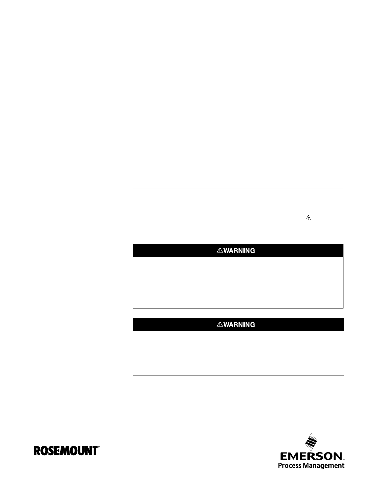
SAFETY MESSAGES Procedures and instructions in this manual may require special precautions to
ensure the safety of the personnel performing the operations. Information that
raises potential safety issues is indicated by a warning symbol ( ). Refer to
the safety messages listed at the beginning of each section before performing
an operation preceded by this symbol.
Explosions could result in death or serious injury:
Verify that the operating environment of the transmitter is consistent with the appropriate
hazardous locations certifications.
Before connecting a HART-based communicator in an explosive atmosphere, make sure
the instruments in the loop are installed in accordance with intrinsically safe or
non-incendive field wiring practices.
Failure to follow safe installation and servicing guidelines could result in death or
serious injury:
Make sure only qualified personnel perform these procedures.
Use the equipment only as specified in this manual. Failure to do so may impair the
protection provided by the equipment.
Do not perform any service other than those contained in this manual unless you are
qualified.
This product is an electrical apparatus and must be installed in the hazardous area in
accordance with the requirements of the EC Type Examination Certificate.
The installation and maintenance must be carried out in accordance with all appropriate
international, national and local standard codes of practice and site regulations for
intrinsically safe apparatus and in accordance with the instructions contained within this
manual. Access to the circuitry must not be made during operation.
www.rosemount.com
Page 10

Reference Manual
00809-0100-4024, Rev BA
Rosemount 5600 Series
September 2005
OVERVIEW This manual provides information about mechanical and electrical installation
of the 5600 Series Radar Level Transmitter. It also describes how to start up
and configure the transmitter. The main purpose of the book is to act as guide
to installing and operating the 5600 Series Radar Level Transmitter. It is not
intended to cover service tasks such as changing circuit boards or internal
software.
Section 2: Mechanical Installation
• Mechanical installation instructions
Section 3: Electrical Installation
• Electrical installation instructions
Section 4: Operation
•Operation
Section 5: HART Configuration
• Commissioning
• Software functions
• Configuration parameters
• Online variables
Section 6: FOUNDATION Fieldbus Configuration
• Commissioning with Delta V
• Software functions
• Configuration parameters
• Online variables
Section 7: 2210 Display Unit Configuration
• Commissioning
Section 8: Maintenance and Troubleshooting
• Troubleshooting techniques for the most common operating problems
for HART and F
OUNDATION fieldbus protocol only.
1-2
Page 11
Reference Manual
00809-0100-4024, Rev BA
September 2005
Rosemount 5600 Series
Appendix A: Reference Data
• Specifications
• Dimensional Drawings
• Ordering information for HART and F
Appendix B: Product Certifications
• Intrinsic safety approval information
• European ATEX directive information
• Approval drawings for HART and fieldbus protocols
Appendix C: Level Transducer Block
• Supplies Level Transducer Block data
Appendix D: Resource Block
• Contains information relating to the operation of the resource block.
Appendix E: Register Transducer Block
• Contains information relating to the operation of the register transducer
block.
OUNDATION fieldbus protocols
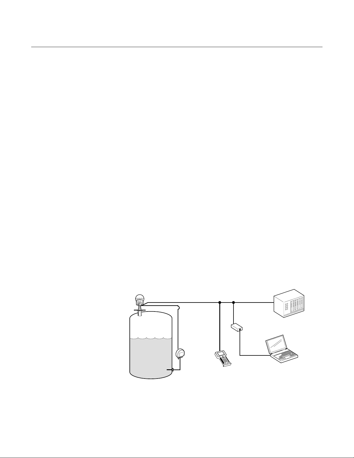
Figure 1-1. System Integration
using the Hand-held
Communicator
The 5600 Series Radar Level Transmitter is a powerful radar level transmitter
suitable for non-contact level measurements in process tanks, storage tanks,
and other types of tanks. It is designed for easy installation and maintenance
free operation.
Together with the Rosemount Radar Master Configuration Tool you are able,
in an easy and user-friendly way, to configure the 5600 transmitters. The
Radar Master program is a Microsoft
®
Windows-based software package
designed for the 5600 transmitters, and offers great assistance, from startup
and commissioning to advanced service. It includes waveform plots, off-line
configuration, logging, and an extensive on-line Help.
4-20 mA/HART
Control System
Remote
Display
(Optional)
Hand-held
Communicator
HART Modem
Configuration PC with
Radar Master software
5600/PDS/BILD_1.EPS
1-3
Page 12
Rosemount 5600 Series
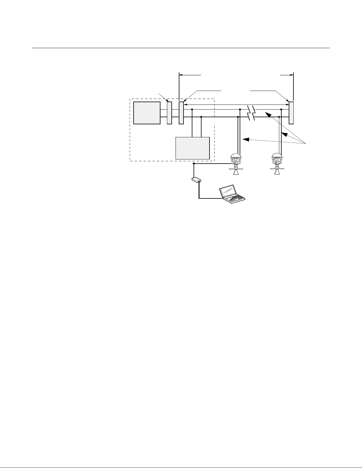
Figure 1-2. System Integration
using F
OUNDATION fieldbus
Integrated Power
Power
Supply
The power supply,
filter, first terminator,
and configuration
tool are typically
located in the
control room.
Note:
Intrinsically safe
installations may allow
fewer devices per I.S.
barrier due to current
limitations.
Conditioner
and Filter
OUNDATION
F
fieldbus
Configuration
Tool
RS485 Modem
6234 ft (1900 m) max
(depending upon cable
characteristics)
Terminators
Fieldbus
Segment
(Trunk)
(Spur)
Reference Manual
00809-0100-4024, Rev BA
September 2005
(Spur)
fieldbus
devices on
segment
Configuration with Radar Master (in
a fieldbus system hooked up to the
device Sensor Bus Port).
Signal
Wiring
5600/PDS/5600_01A.EPS
For stand-alone systems, or as a complement to a PC or a control system,
you can monitor level data using one or two analog outputs depending on the
particular hardware configuration.
As an option, your Rosemount 5600 Radar Level Transmitter can be
equipped with an easy-to-use Rosemount 2210 Display Panel. It offers
basically the same functionality as the Radar Master package. Four sturdy
softkeys give you access to configuration routines, service functions, and
level monitoring.
Measurement Principle
The level of the product in the tank is measured by radar signals transmitted
from the antenna at the tank top. After the radar signal is reflected by the
product surface the echo is picked up by the antenna. As the signal is varying
in frequency the echo has a slightly different frequency compared to the signal
transmitted at that moment. The difference in frequency is proportional to the
distance to the product surface, and can be accurately calculated. This
method is called FMCW (Frequency Modulated Continuous Wave) and is
used in all high performance radar transmitters.
1-4
Page 13
Reference Manual
00809-0100-4024, Rev BA
September 2005
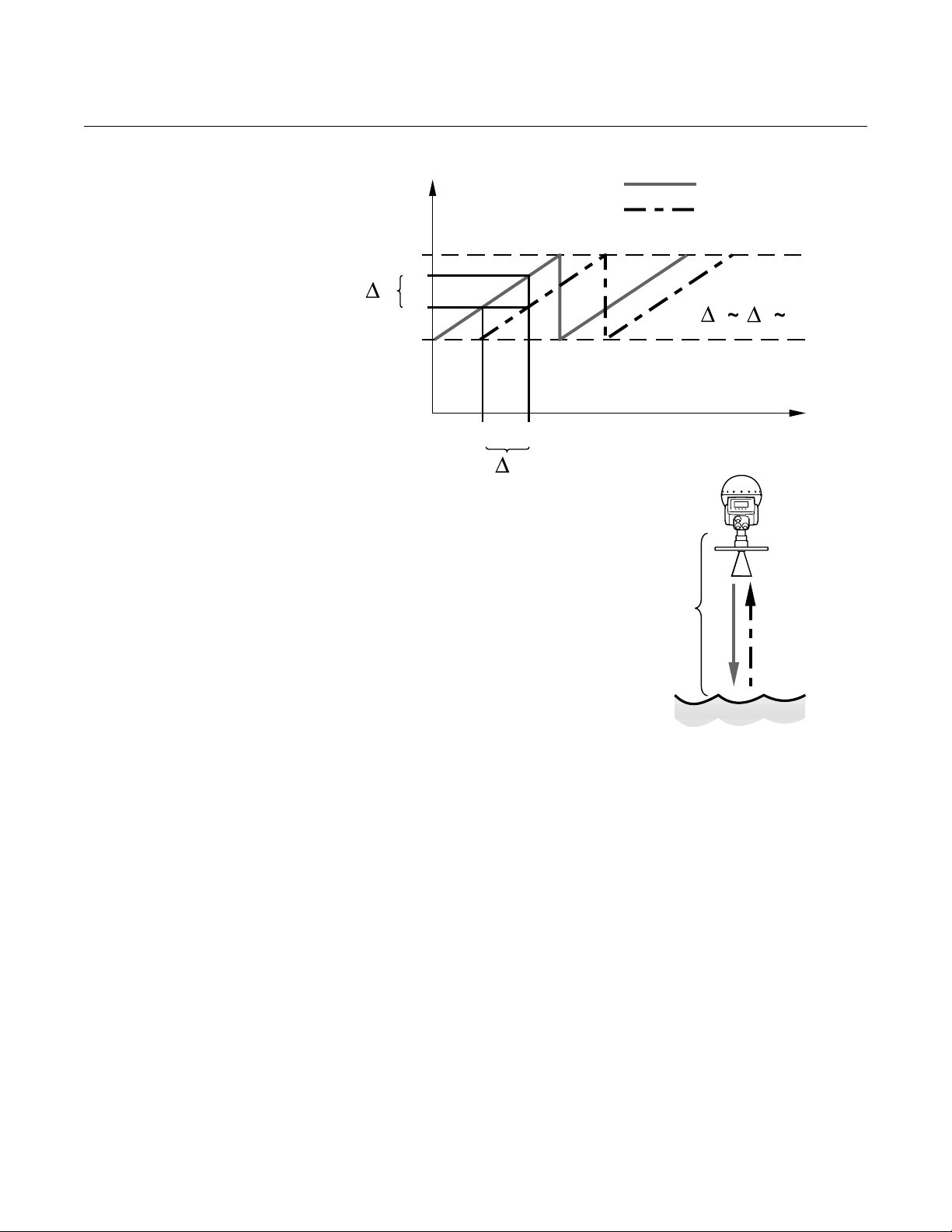
Figure 1-3. Frequency
Modulated Continuous Wave
Frequency (GHz)
f
max
f
1
f
f
0
f
min
t
t
0
1
t
The FMCW method is based on
a radar sweep with continuous
changes in frequency.
Rosemount 5600 Series
Transmitted
Reflected
td
f
Time
d
f
f
1
0
5600_PDS_FMCW.EPS
1-5
Page 14

Rosemount 5600 Series
The 5600 Series Radar Level Transmitter sends a microwave signal with a
continuously varying frequency towards the product surface. When the
reflected signal returns to the antenna, it is mixed with the outgoing signal.
Since the transmitter continuously changes the frequency of the transmitted
signal, there will be a difference in frequency between the transmitted and the
reflected signals.
The transmitter mixes the two signals, resulting in a low frequency signal
which is proportional to the distance to the product surface. This signal can be
measured very accurately allowing fast, reliable, and accurate level
measurements.
The 5600 Series Radar Level Transmitter uses micro frequency to reduce
sensitivity to vapor, foam, and contamination of the antenna, and keeps the
radar beam narrow in order to minimize influence from walls and disturbing
objects.
The 5600 Series Radar Level Transmitter uses Fast Fourier Transformation
(FFT), which is a well established signal processing technique, to obtain a
frequency spectrum of all echoes in the tank. From this frequency spectrum
the surface level is extracted. In combination with the echofixer, FFT allows
measurements in tanks with agitators, mixers and other disturbing objects.
The echofixer provides a technique to adapt measurements to various
situations, by using information from previous measurements.
Reference Manual
00809-0100-4024, Rev BA
September 2005
SPECIFIC FCC
REQUIREMENTS
(USA ONLY)
This device complies with part 15 of the FCC Rules. Operation is subject to
the following two conditions: (1) This device may not cause harmful
interference, and (2) this device must accept any interference received,
including interference that may cause undesired operation.
The Rosemount 5600 generates and uses radio frequency energy. If it is not
installed and used properly (in strict accordance with the manufacturer´s
instructions) it may violate FCC regulations on radio frequency emission.
Installation on non-metallic tanks, tanks with open manholes,
external-floating-roof tanks without stillpipes etc. are not covered by this
certificate, and require a Part 90 site-license. If you have an installation like
this, contact your local Emerson Process Management representative for help
with the necessary license application.
1-6
Page 15
Reference Manual
00809-0100-4024, Rev BA
Rosemount 5600 Series
September 2005
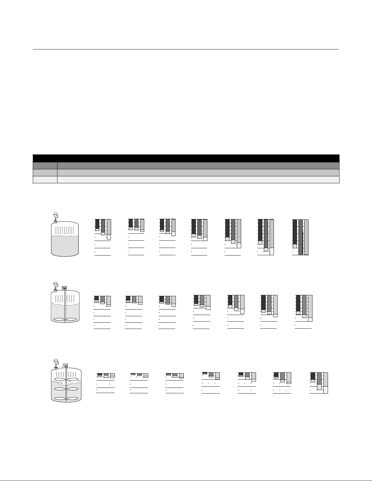
Measuring Range The diagrams below show how the measuring range is influenced by the
antenna type, dielectric constant of the liquid (ε
For optimum performance the maximum measuring distance should be kept
within the range indicated with darker color in the diagrams. Values are valid
for free propagation measurement without still-pipes (bridles).
) and the process conditions.
r
For liquids with ε
that are smaller than 1.9 such as liquefied gases, an 8 inch
r
or bigger diameter antenna is recommended if measurement is done with free
propagation. In this case the measuring range in calm surface tanks is in
typical cases 50 ft. (15 m).
To increase the measuring range further in turbulent tanks, a still-pipe can be
used. For still-pipe mounted 5600 transmitters the typical measuring range is
115-160 ft. (35-50 m) in turbulent tanks with liquids having ε
Table 1-1. Categories of liquids
a Oil, gasoline and other hydrocarbons, petrochemicals (dielectric constant, ε
b Alcohols, concentrated acids, organic solvents, oil/water mixtures and acetone (ε
c Conductive liquids, e.g. water based solutions, dilute acids and alkalis (ε
Figure 1-4. Applications with calm product surface
3” Cone
abc abc abc abc
33 (10)
66 (20)
98 (30)
131 (40)
164 (50)
4” Process
Seal
abc abc
33 (10)
66 (20)
98 (30)
131 (40)
164 (50)
33 (10)
66 (20)
98 (30)
131 (40)
164 (50)
(1)
6” Process
Seal
00
Rod/
4”Cone
33 (10)
66 (20)
98 (30)
131 (40)
164 (50)
> 10)
r
33 (10)
66 (20)
98 (30)
131 (40)
164 (50)
=1.9-4.0)
r
=4.0-10)
r
6” Cone
0000
33 (10)
66 (20)
98 (30)
131 (40)
164 (50)
Figure 1-5. Applications where the product is gently stirred, causing minor turbulence
4” Process
3” Cone
abc abc abc
33 (10)
66 (20)
98 (30)
131 (40)
164 (50) 164 (50) 164 (50) 164 (50)
Seal
33 (10)
66 (20)
98 (30)
131 (40)
33 (10)
66 (20)
98 (30)
131 (40)
6” Process
Seal
000
131 (40)
Rod/
4”Cone
abc abc
33 (10)
66 (20)
98 (30)
6” Cone
00
33 (10)
66 (20)
98 (30)
131 (40)
164 (50) 164 (50)
33 (10)
66 (20)
98 (30)
131 (40)
8” Cone
(1)
8” Cone
abc
0
less than 1.9.
r
Parabolic
abc
0
33 (10)
66 (20)
98 (30)
131 (40)
164 (50)
Parabolic
0
33 (10)
66 (20)
98 (30)
131 (40)
164 (50)
5600-OC_1AA
abc
5600-OC_2AB
Figure 1-6. Applications with turbulent product surface conditions
33 (10)
66 (20)
98 (30)
(1) Measuring range in ft. (m).
1-7
4” Process
3” Cone
abc abc abc
33 (10)
66 (20)
98 (30)
Seal
Note: 4” and 6” Process Seal Cones are not
recommended for turbulent conditions
33 (10)
66 (20)
98 (30)
6” Process
Seal
000
33 (10)
66 (20)
98 (30)
(1)
Rod/
4”Cone
abc abc
6” Cone
00
33 (10)
66 (20)
98 (30)
33 (10)
66 (20)
98 (30)
8” Cone
abc
0
33 (10)
66 (20)
98 (30)
Parabolic
abc
0
5600-OC_3AA
Page 16

Rosemount 5600 Series
Minimum Measuring Distance
The minimum distance the radar can measure depends on the antenna
selected. Typically the level can come as close as 0.79-in. (20 mm) from the
antenna tip, before the software disregards the signal. Being this close to the
antenna may however reduce the measurement accuracy. Table 2-1 on
page 2-3 includes the value Hold Off Distance, which is the default setting for
this minimum distance. It can not be decreased, only increased if needed.
Measuring Close to Tank Bottom
When measuring products with low dielectric constants, i.e. DC range 1.4 -
2.5, some of the radar energy will go thru the product. This could lead to that
the radar will see the Flat Tank Bottom, even though there is a small amount
of product covering the bottom of the tank. This could reduce the accuracy of
the measurement at these lower product levels. This could occur at product
levels of 4-6 inch (100-150 mm) or lower, but depends on the product as well
as the tank bottom type. There are special software settings that could
improve this situation, or alternatively mechanical changes could be
implemented to minimize the influence from the bottom of the tank.
Reference Manual
00809-0100-4024, Rev BA
September 2005
UNPACKING YOUR 5600
TRANSMITTER
Verify that you have received:
• 1 box with the transmitter head. This box also includes a Hook spanner
(used to open the terminal compartments), Reference manual
(00809-0100-4024), Rosemount Radar Master CD-Rom
(0822-0100-4757), and a Quick Installation Guide.
• 1 box with the antenna. This box contains the complete antenna
assembly, including the Waveguide Tube (see page 2-6) which is to be
inserted in the transmitter head foot.
NOTE
If you ordered flanges, the flanges are typically stored at the bottom of the
bigger wooden crate that the transmitter is delivered in. They are held in place
with bolts and nuts.
1-8
Page 17

Reference Manual
00809-0100-4024, Rev BA
Rosemount 5600 Series
September 2005
SERVICE SUPPORT If you have reason to believe that your Rosemount 5600 Radar Level
Transmitter may need to be returned for service, contact the appropriate
representative.
Within USA: Please contact a Level Applications Support Specialist at Rosemount
Customer Central (1-800-999-9307). They will help you determine the best
course of action, and may transfer you to either an Order Administrator or to
the Rosemount North American Response Center (NARC) to arrange for the
return of your transmitter for service or repair.
Outside USA: For Service Support outside the United States, please contact your nearest
Rosemount Representative.
NOTE
Most radar problems encountered in the field are applications-related and can
best be dealt with while the transmitter is installed.
The representative will assist you with any needed information or materials.
The representative will ask for the following information:
• Product model
• Serial numbers
• The last process material to which the product was exposed
The representative will provide:
• A Return Material Authorization (RMA) number
• Instructions and procedures that are necessary to return goods that
were exposed to hazardous substances
Spare Parts
Any substitution of non-recognized spare parts may jeopardize safety. Repair,
e.g. substitution of components etc., may also jeopardize safety and is under
no circumstances allowed.
1-9
Page 18

Rosemount 5600 Series
Reference Manual
00809-0100-4024, Rev BA
September 2005
1-10
Page 19
Reference Manual
00809-0100-4024, Rev BA
September 2005
Rosemount 5600 Series
Section 2 Mechanical Installation
Safety Messages . . . . . . . . . . . . . . . . . . . . . . . . . . . . . . . . . page 2-1
Introduction . . . . . . . . . . . . . . . . . . . . . . . . . . . . . . . . . . . . . page 2-2
General Installation Requirements . . . . . . . . . . . . . . . . . . page 2-2
Wave Guide Tubes . . . . . . . . . . . . . . . . . . . . . . . . . . . . . . . page 2-6
Mounting the Rod Antenna, Flanged Version . . . . . . . . . page 2-7
Mounting the Rod Antenna, Threaded Version . . . . . . . . page 2-11
Mounting the Cone Antenna - PTFE sealing . . . . . . . . . . page 2-14
Mounting the Cone Antenna - Quartz sealing . . . . . . . . . page 2-17
Mounting the Process Seal Antenna . . . . . . . . . . . . . . . . page 2-22
Mounting the Parabolic Antenna . . . . . . . . . . . . . . . . . . . . page 2-31
Mounting the Extended Cone Antenna . . . . . . . . . . . . . . . page 2-37
Mounting the Cone Antenna with Flushing Connections page 2-43
SAFETY MESSAGES Procedures and instructions in this manual may require special precautions to
ensure the safety of the personnel performing the operations. Information that
raises potential safety issues is indicated by a warning symbol ( ). Refer to
the safety messages listed at the beginning of each section before performing
an operation preceded by this symbol.
Explosions could result in death or serious injury:
Verify that the operating environment of the transmitter is consistent with the appropriate
hazardous locations certifications.
Before connecting a HART-based communicator in an explosive atmosphere, make sure
the instruments in the loop are installed in accordance with intrinsically safe or
non-incendive field wiring practices.
This product is an electrical apparatus and must be installed in the hazardous area in
accordance with the requirements of the EC Type Examination Certificate.
The installation and maintenance must be carried out in accordance with all appropriate
international, national and local standard codes of practice and site regulations for
intrinsically safe apparatus and in accordance with the instructions contained within this
manual. Access to the circuitry must not be made during operation.
www.rosemount.com
Page 20

Rosemount 5600 Series
Failure to follow safe installation and servicing guidelines could result in death or
serious injury:
Make sure only qualified personnel perform these procedures.
Use the equipment only as specified in this manual. Failure to do so may impair the
protection provided by the equipment.
Do not perform any service other than those contained in this manual unless you are
qualified.
The quartz seal is not suitable for use in environments where there is a risk for variations or
other mechanical impacts.
For quartz seal, mechanical shocks may permanently damage the seal. A damaged tank
seal must be replaced. Replacement must be done when the tank is unpressurized.
The customer must always make sure that exposed material of antenna and tank seal is
compatible with the tank content, e.g. the quartz seal is not suitable for use with
Hydrofluoric acid (HF).
A damaged quartz tank seal will typically cause one or many disturbance echoes which will
be seen in a tank spectrum plot during gauge configuration.
Reference Manual
00809-0100-4024, Rev BA
September 2005
INTRODUCTION This section describes the mechanical installation. Start by reading the
General Installation Requirements for your antenna. This includes Nozzle and
Free Space Requirements. The last part of this section includes mounting
instructions for all antenna types, including special requirements for still
pipe/bridle installations and applications.
Tools The following set of tools are needed for installation of a 5600 Series Radar
Level Transmitter:
• Screw driver.
• Adjustable wrench.
• Allen key.
• Circlip plier (snap ring plier).
• Hook spanner (comes delivered with the transmitter).
GENERAL
INSTALLATION
REQUIREMENTS
Position the transmitter in a way that allows the microwaves to propagate
without disturbance from the tank wall. In order to achieve optimum
performance you should consider the following recommendations:
• Try to avoid obstacles in the radar beam.
• Mount the transmitter away from pipe inlets which cause turbulent
conditions.
• Choose as large antenna as possible to ensure maximum antenna
gain.
• For best measurement performance it is recommended that the
antenna tip ends outside the nozzle, see Figure 2-2.
Customer Supplied
Flanges
2-2
The simple design of cone and rod antennas tank connection allows the use
of customer supplied flanges. If a hole is drilled in a standard blind flange the
pressure performance may be reduced. In such a case the flange should be
marked with new rating for Maximum Allowed Working Pressure (MAWP).
Page 21
Reference Manual
00809-0100-4024, Rev BA
September 2005
Rosemount 5600 Series
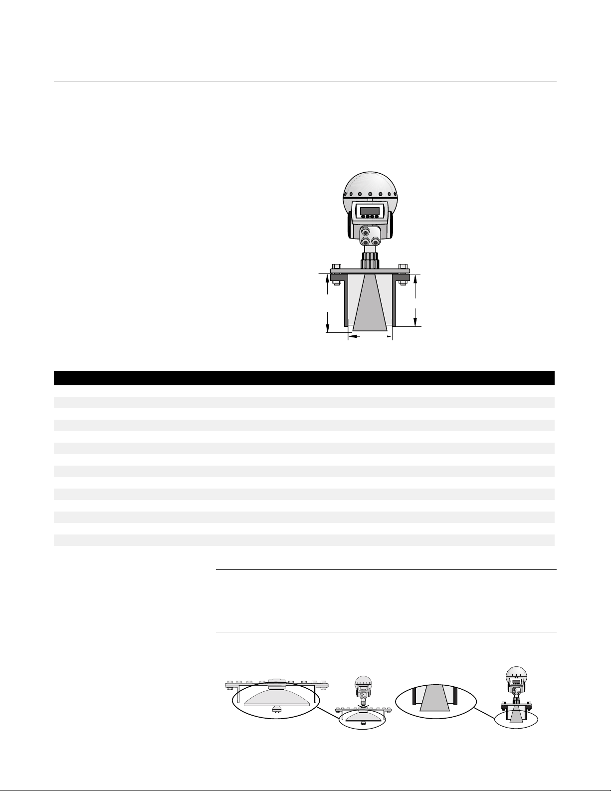
Nozzle Requirements In order to allow the microwaves to propagate undisturbed, the nozzle
dimensions should be kept within the specified limits for the different
antennas.
Figure 2-1. Nozzle
Requirements, see Table 2-1
Hold Off
Distance
Ø
min
L
maximum
SOCKET_REQUIREMENT_02
Table 2-1. Nozzle Requirements in inches (millimeters)
Antenna L
Rod100 3.9 (100) or less 1.6 (43) 3.9 (100) 23.6 (600)
Rod250 9.8 (250) or less 1.6 (43) 9.8 (250) 30.7 (780)
Cone 3 in. 3.7 (95) or less 2.9 (75) 9.6 (245) 4.7 (120)
Cone 4 in. 5.9 (150) or less 3.8 (98) 11.8 (300) 6.7 (170)
Cone 6 in. 10.2 (260) or less 5.7 (146) 16.1 (410) 11.0 (280)
Cone 8 in. 14.6 (370) or less 7.6 (194) 20.6 (525) 15.8 (400)
Parabolic 6.3 (160) or less 19.7 (500) 23.6 (600) 7.9 (200)
Process Seal 4 in. 11.8 (300) or less 3.9 (100) 11.8 (300) 7.9 (200)
Process Seal 6 in. 11.8 (300) or less 5.9 (150) 11.8 (300) 7.9 (200)
Extended Cone 3 in. 19.5 (495) or less 3.0 (75) 19.5 (495) 20.5 (520)
Extended Cone 4 in. 19.5 (495) or less 3.9 (98) 19.5 (495) 20.5 (520)
Extended Cone 6 in. 19.5 (495) or less 5.8 (146) 19.5 (495) 20.5 (520)
Flushing Cone 4 in. 5.9 (150) or less 3.9 (98) 11.8 (300) 6.7 (170)
Flushing Cone 6 in. 10.2 (260) or less 5.8 (146) 16.1 (410) 11.0 (280)
Flushing Cone 8 in. 14.6 (370) or less 7.6 (194) 20.7 (525) 15.8 (400)
recommended
Diam
min
L
maximum
Hold Off Distance
NOTE
For Parabolic Antennas mounted in solid applications, minimize the L
Distance to allow the Parabolic Antenna to reach into the tank. See
Measuring Solids with a Rosemount 5600 Non-contacting Radar (part
number 00830-0800-4024).
Figure 2-2. Antenna Tip Outside
Nozzle to get the Best
Measurement Performance
Parabolic Antenna
Cone Antenna
SOCKET_REQ
2-3
Page 22
Rosemount 5600 Series
Free Space
Requirements
Figure 2-3. Free Space
Requirements, see Table 2-2
Reference Manual
00809-0100-4024, Rev BA
September 2005
A
B
C
D
Table 2-2. Free Space Requirements
A. Service Space Width Distance in. (mm)
All antennas 22 (550)
B. Service Space Height
Antenna Distance in. (mm)
Rod 27 (700)
Cone, Extended Cone, Flushing Cone 25 (650)
Process Seal 31 (800)
Parabolic 27 (700)
C. Inclination
Antenna Maximum Angle
Rod 3°
Cone 1°
Process Seal 3°
Parabolic 3°
D. Minimum distance to tank wall
Antenna Distance in. (mm)
Rod 24 (600)
Cone 24 (600)
Process Seal 24 (600)
Parabolic 24 (600)
(1) Mounting closer to the tank wall may be allowed if reduced accuracy is accepted.
(1)
FREESPACE_V2
2-4
Page 23
Reference Manual
00809-0100-4024, Rev BA
September 2005
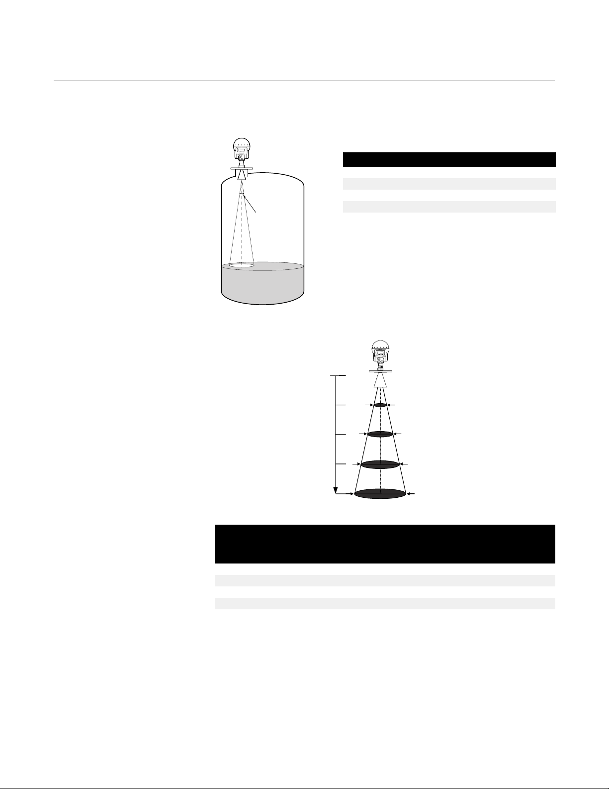
Beam Width
Rosemount 5600 Series
Figure 2-4. Beam width angle,
see Table 2-3
Figure 2-5. Beam width
distance, see Table 2-4
Table 2-3. Beam width angle
Antenna Beam Width
Cone 3 in. 25°
Rod/Cone 4 in./ Process Seal 4 in. 21°
Cone 6 in./ Process Seal 6 in. 18°
Beam
Angle
BILD_24
Cone 8 in. 15°
Parabolic 10°
5m
Special Antennas and
Space Requirements
Reference
10m
Distance
15m
20m
BEAMAREA
Table 2-4. Beam width distance
Diameter of radiated area at different
distances from flange, ft. (m)
Antenna
Cone 3 in. 7.2 (2.2) 14 (4.4) 22 (6.7) 29 (8.9)
Rod/Cone 4 in./ Process Seal 4 in. 6.2 (1.9) 12 (3.7) 18 (5.6) 24 (7.4)
Cone 6 in./ Process Seal 6 in. 5.2 (1.6) 10 (3.1) 15 (4.7) 21 (6.3)
Cone 8 in. 3.3 (1.0) 7.9 (2.4) 13 (3.9) 17 (5.2)
Parabolic 3.0 (0.9) 5.6 (1.7) 8.5 (2.6) 11 (3.5)
16 ft (5 m) 33 ft (10 m) 49 ft (15 m) 66 ft (20 m)
Pipe Installation
See page 2-40 and page 2-25.
Extended Cone Installation
See page 2-40 and page 2-37.
2-5
Page 24
Rosemount 5600 Series
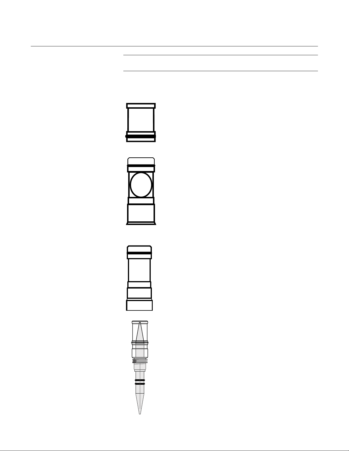
WAVE GUIDE TUBES NOTE
The Waveguide Tubes are parts of the antenna kits.
Reference Manual
00809-0100-4024, Rev BA
September 2005
Cone and Rod Antenna
• For model codes 1xx, 2xx, 7xx, and 9xx
(with PTFE Seal for Cone)
• Distinguishing features:
a. Length: 1.57-in. (40 mm)
Process Seal
• For model codes 34S and 36S.
• Distinguishing features:
a. Length: 2.93-in. (74.5 mm)
b. O-ring on the inside
Parabolic
• For model codes 45S and 46S
• Distinguishing features:
a. Length: 2.93-in. (74.5 mm)
b. No o-ring on the inside
Cone Antenna with Quartz Seal
• Model code option Q (with Quartz Seal)
• Distinguishing features:
a. Complete assembly
b. No loose waveguide tube
• Not available as spare part. If spare part is
required, order complete antenna.
2-6
Page 25
Reference Manual
00809-0100-4024, Rev BA
September 2005
MOUNTING THE ROD
ANTENNA, FLANGED
VERSION
Rosemount 5600 Series
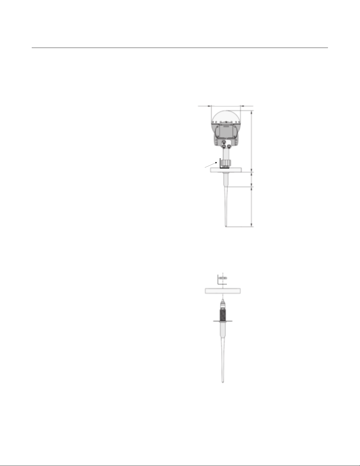
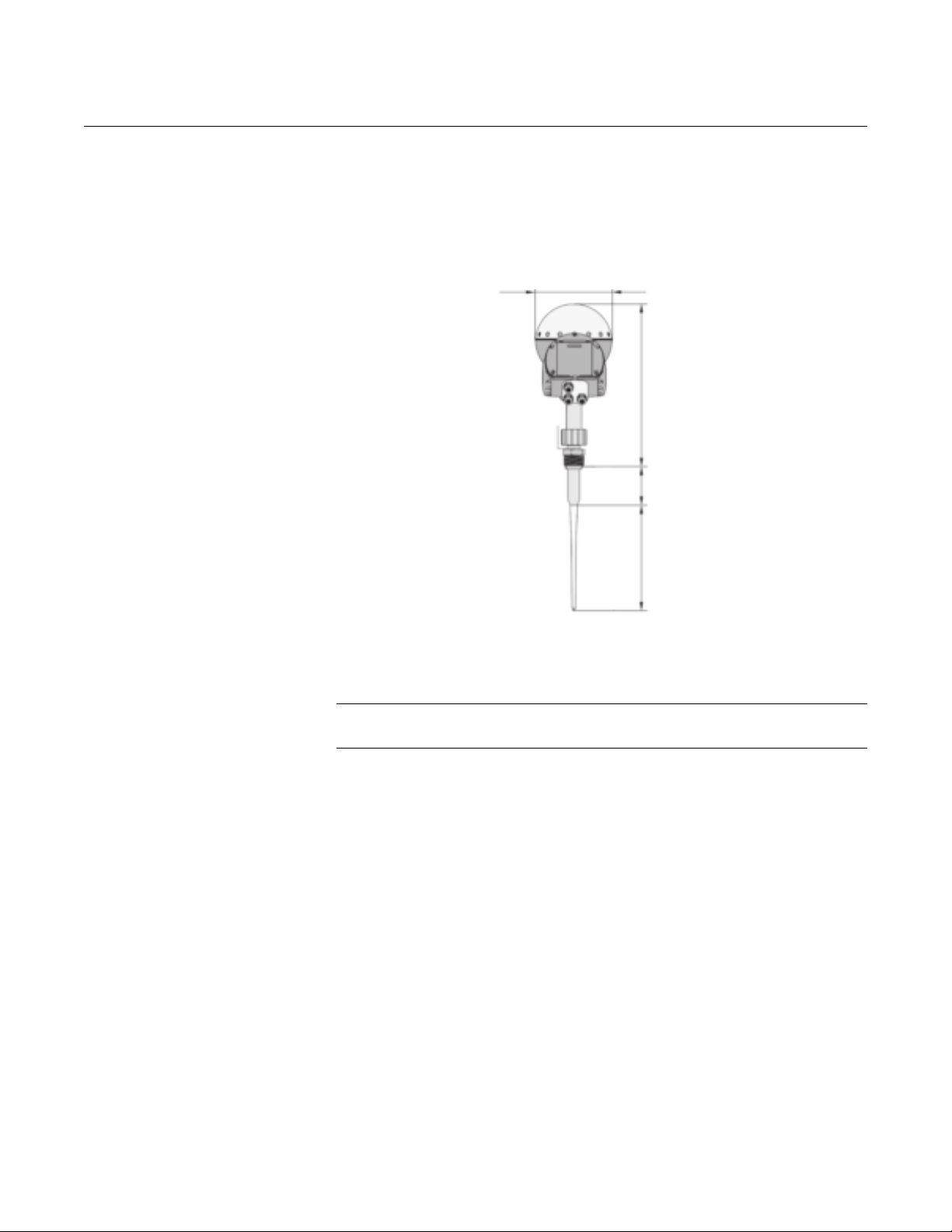
Figure 2-6. Rod Antenna
Dimensions, Flanged Version
Figure 2-7. Mount the flange
7.87 (200)
15.75 (400)
Antenna Label
Plate
NOTE
Dimensions are in
inches (millimeters)
Inactive length 3.94 (100) or
Inactive length 9.84 (250)
11.81 (3 00)
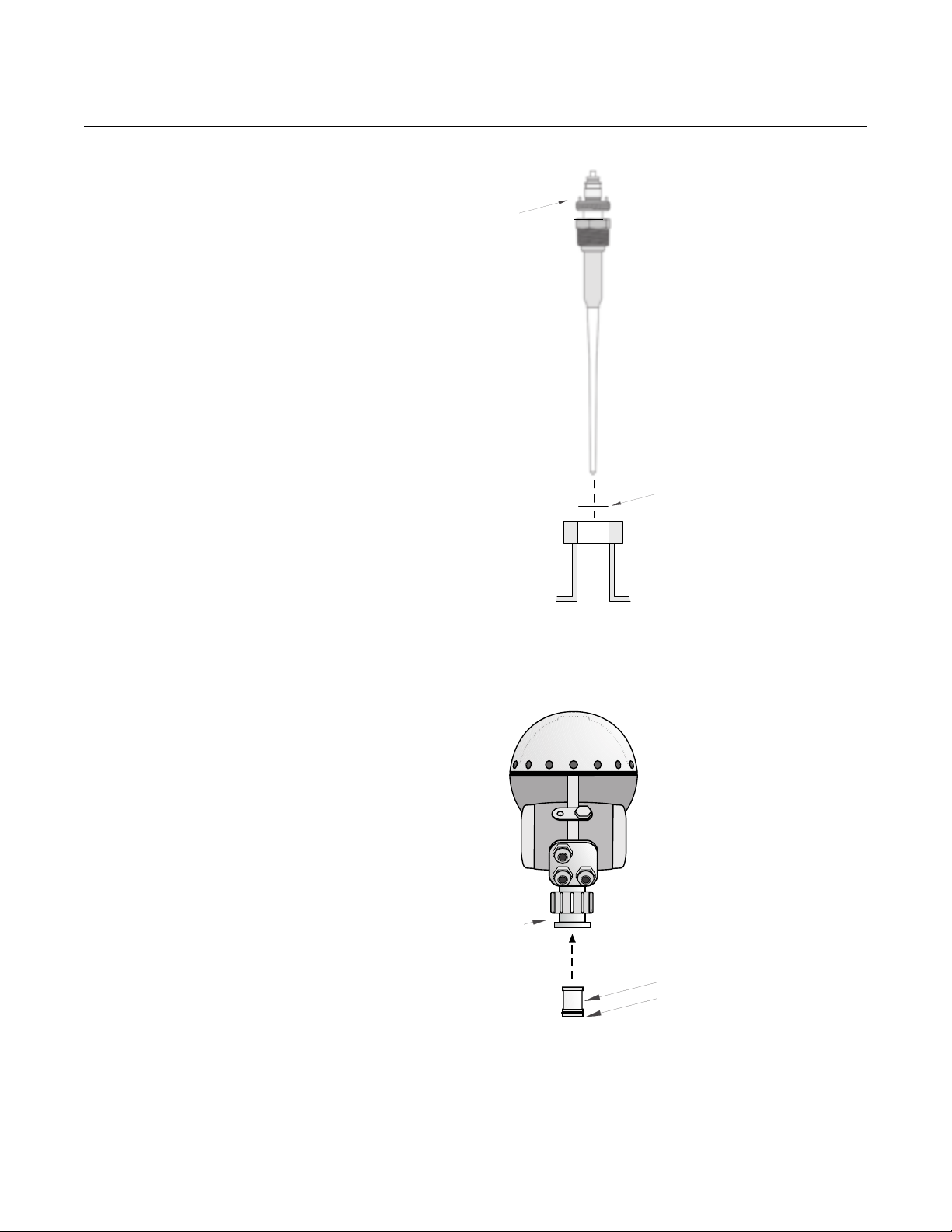
1. Mount the flange on top of the rod plate. Make sure the bottom side of
the flange is flat and all parts are clean and dry.
ROD_MOUNT_DIMENSIONS
ROD_MOUNT_FLANGE
2-7
Page 26
Rosemount 5600 Series
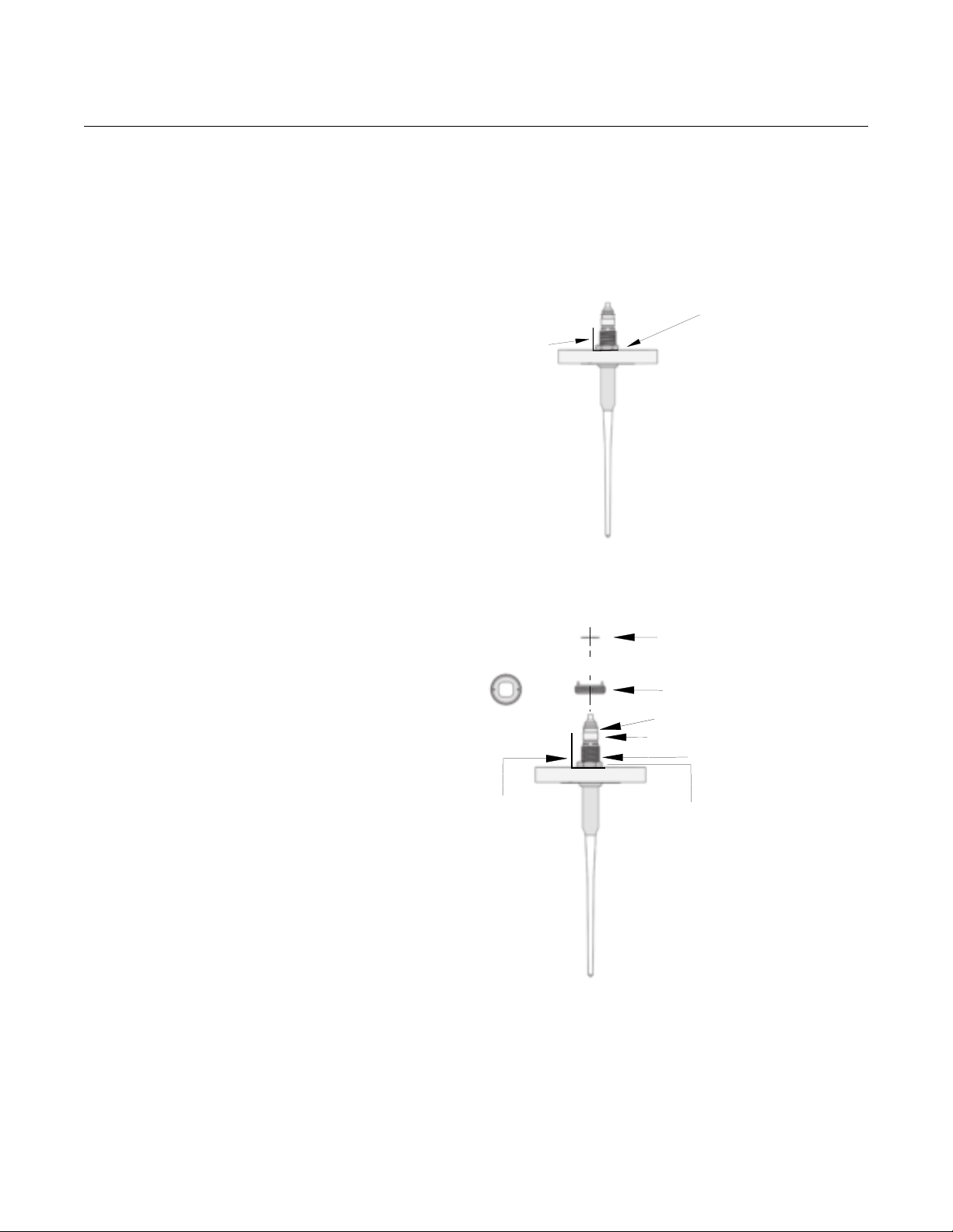
2. Secure the flange and label plate with the locking nut. Make sure the nut
fits tightly to the flange.
Figure 2-8. Secure the flange
with the locking nut
Reference Manual
00809-0100-4024, Rev BA
September 2005
Locking Nut
Figure 2-9. Mounting the
adapter
Antenna Label
Plate
ROD_MOUNT_NUT
3. Mount the adapter on top of the sleeve.
Locking Ring
Adapter
O-ring
Wave guide
Sleeve
2-8
Antenna
Label Plate
Nut
ROD_MOUNT_APDATER
Page 27
Reference Manual
00809-0100-4024, Rev BA
September 2005
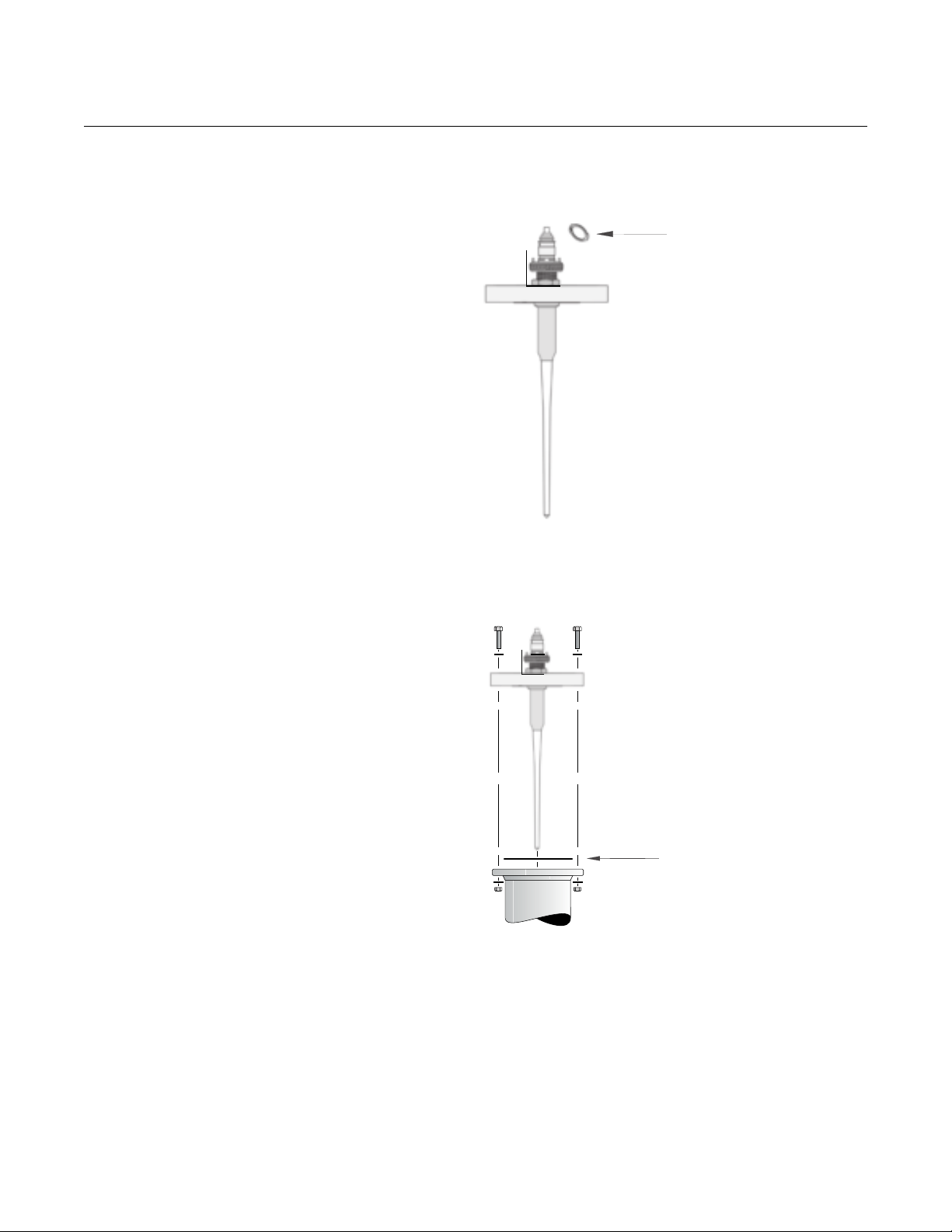
Figure 2-10. Use the locking ring
to secure the adapter
Rosemount 5600 Series
4. Secure the adapter with the locking ring.
Locking Ring
Figure 2-11. Mount the flange
and rod antenna on the nozzle
ROD_MOUNT_RING
5. Carefully fit the flange and the rod antenna on the tank nozzle with an
appropriate gasket in between. Tighten with screws and nuts.
Gasket
ROD_MOUNT.EPS
2-9
Page 28
Rosemount 5600 Series
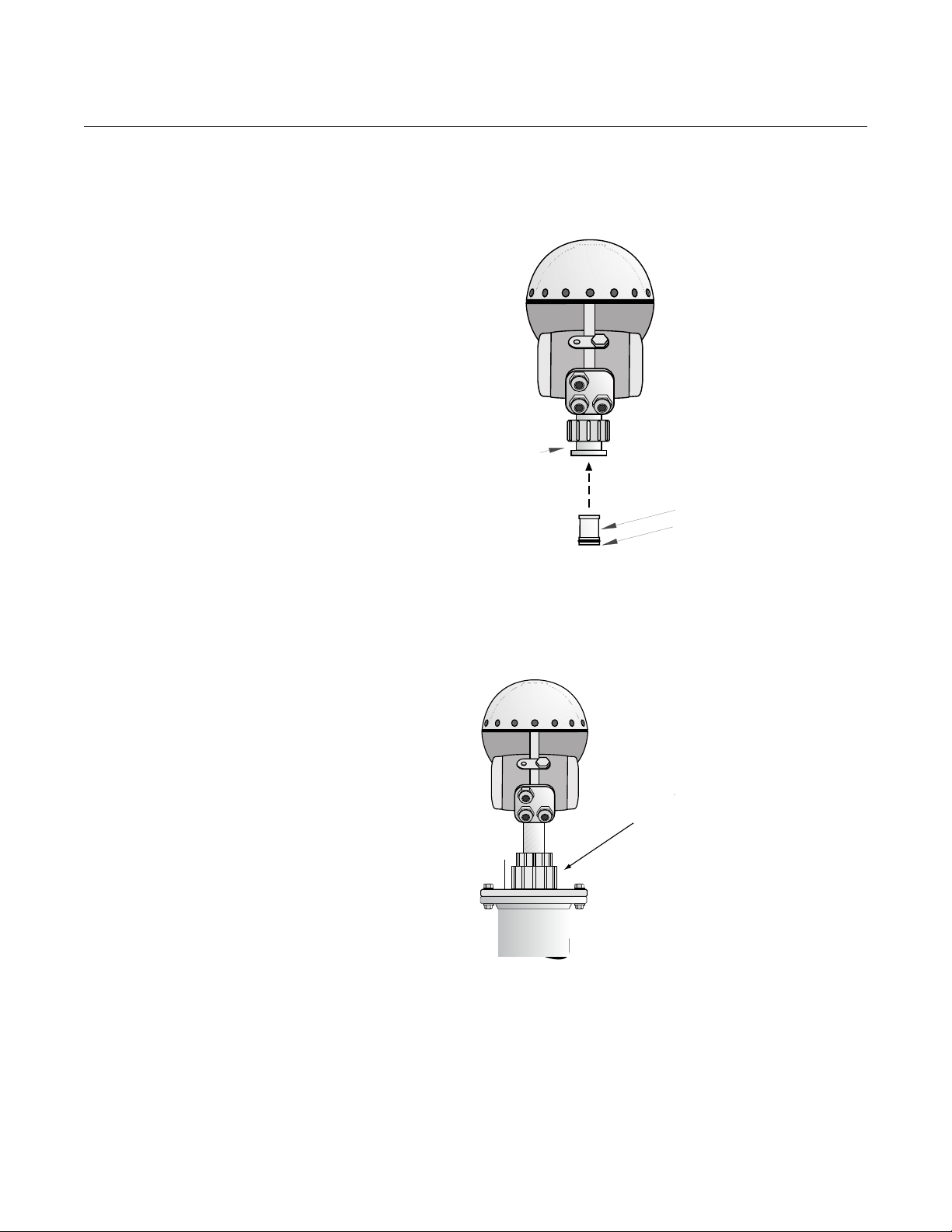
6. Insert the wave guide tube into the upper wave guide. Make sure the
o-ring at the lower end of the wave guide tube is in place.
Figure 2-12. Mount the
transmitter head
Reference Manual
00809-0100-4024, Rev BA
September 2005
Upper Wave Guide
WAVEGUIDE_TUBE.EPS
Wave Guide Tube
O-ring
Figure 2-13. Completed
mechanical installation
7. Place the protection sleeve on the flange. Mount the transmitter head
and tighten the nut. Check that the guide pins on the adapter enter the
corresponding grooves on the upper wave guide.
Protection
Sleeve
TH40HEAD_NOZZLE.EPS
8. Proceed with the electrical installation.
2-10
Page 29
Reference Manual
00809-0100-4024, Rev BA
September 2005
MOUNTING THE ROD
ANTENNA, THREADED
VERSION
Figure 2-14. Rod Antenna
Dimensions, Threaded Version
Rosemount 5600 Series
7.87 (200)
15.75 (400)
Inactive length 3.94 (100) or
Inactive length 9.84 (250)
NOTE
Dimensions are in
inches (millimeters)
11.81 (300)
1. Carefully fit the rod antenna into the threaded nozzle and screw it in
place.
NOTE
For adapters with NPT threads, pressure-tight joints may require a sealant.
5600/9150074-921AA.EPS
2-11
Page 30
Rosemount 5600 Series
Figure 2-15. Mount the rod
antenna
Reference Manual
00809-0100-4024, Rev BA
September 2005
Antenna Label Plate
Gasket for BSP
(G) threads
Figure 2-16. Mount the
transmitter head
ROD_MOUNT_BSP.EPS
2. Insert the wave guide tube into the upper wave guide. Make sure the
o-ring at the lower end of the wave guide tube is in place.
Upper Wave Guide
Wave Guide Tube
O-ring
WAVEGUIDE_TUBE.EPS
2-12
Page 31

Reference Manual
00809-0100-4024, Rev BA
September 2005
Figure 2-17. Completed
mechanical installation
Rosemount 5600 Series
3. Place the protection sleeve on the flange. Mount the transmitter head
and tighten the nut. Check that the guide pins on the adapter enter the
corresponding grooves on the upper wave guide.
Protection
Sleeve
4. Proceed with the electrical installation.
TH40HEAD_NOZZLE_BSP.EPS
2-13
Page 32

Rosemount 5600 Series
MOUNTING THE CONE
ANTENNA - PTFE
SEALING
Reference Manual
00809-0100-4024, Rev BA
September 2005
Figure 2-18. Cone Antenna
Dimensions
7.87 (200)
15.75 (400)
Junction Box
3.74 (95) (3 in. Cone)
5.91 (150) (4 in. Cone)
10.24 (260) (6 in. Cone)
14.57 (370) (8 in. Cone)
NOTE
Dimensions are in
inches (millimeters)
2.76 (70)(3 in. Cone)
3.66 (93) (4 in. Cone)
5.55 (141) (6 in. Cone)
7.44 (189) (8 in. Cone)
1. Remove locking ring and adapter from antenna.
2. Mount the flange on top of the cone plate. Make sure that the bottom
side of the flange is flat and all parts are clean and dry.
Figure 2-19. Mount the flange
2-14
Antenna Label Plate
FLANGE_MOUNT_PTFE_50%
Page 33

Reference Manual
00809-0100-4024, Rev BA
September 2005
Figure 2-20. Secure the flange
with the locking nut
Rosemount 5600 Series
3. Secure the flange with the locking nut.
Make sure that the nut fits tightly to the flange.
CONE_FLANGE_ASSY_PTFE_50%
4. Mount the adapter on top of the sleeve.
Figure 2-21. Mounting the
adapter
Figure 2-22. Use the locking ring
to secure the adapter
Locking Ring
Top view of
adapter
5. Secure the adapter with the locking ring.
Locking Ring
Adapter
O-ring
Wave guide unit
Sleeve
ADAPTER_TOPVIEW,
ADAPTER_MOUNT_PTFE
ADAPTER_LOCKRING_PTFE
2-15
Page 34

Rosemount 5600 Series
6. Carefully fit the flange and the cone antenna on the tank nozzle.
7. Tighten with screws and nuts.
Figure 2-23. Mount the flange
and cone antenna on the nozzle
Reference Manual
00809-0100-4024, Rev BA
September 2005
Gasket
Figure 2-24. Mount the
transmitter head
CONETANK_PTFE.EPS
8. Insert the wave guide tube into the upper wave guide.
Make sure the gasket at the lower end of the wave guide tube is in place.
Upper Wave Guide
WAVEGUIDE_TUBE
Wave guide tube
O-ring
2-16
Page 35

Reference Manual
00809-0100-4024, Rev BA
September 2005
Figure 2-25. Completed
mechanical installation
Rosemount 5600 Series
9. Place the protection sleeve on the flange.
Mount the transmitter head and tighten the nut. Check that the guide pins
on the adapter enter the corresponding grooves on the upper wave
guide.
Protection
Sleeve
MOUNTING THE CONE
ANTENNA - QUARTZ
SEALING
Figure 2-26. Cone Antenna
Dimensions
TH40HEAD_NOZZLE1
10. Proceed with the electrical installation.
7.87 (200)
15.75 (400)
Junction Box
3.74 (95) (3 in. Cone)
5.91 (150) (4 in. Cone)
10.24 (260) (6 in. Cone)
14.57 (370) (8 in. Cone)
NOTE
Dimensions are in
inches (millimeters)
2.76 (70)(3 in. Cone)
3.66 (93) (4 in. Cone)
5.55 (141) (6 in. Cone)
7.44 (189) (8 in. Cone)
2-17
Page 36

Rosemount 5600 Series
Antennas including tank seal of quartz material are suitable for high pressure
applications.
NOTE
The quartz seal shall be protected against mechanical shocks or impacts. It is
important to handle the antenna carefully in order to avoid any mechanical
stresses such as bending or pressing the sealing.
1. Remove locking ring and adapter from antenna.
2. Mount the range on top of the cone plate. Make sure the bottom side of
the flange is flat and all parts are clean and dry.
Figure 2-27. Mount the flange
Reference Manual
00809-0100-4024, Rev BA
September 2005
Flange
Note:
No gasket
on top of
this plate
FLANGE_MOUNT_QUARTZ
2-18
Page 37

Reference Manual
00809-0100-4024, Rev BA
September 2005
Figure 2-28. Secure the flange
with the locking nut
Rosemount 5600 Series
3. Secure the flange and label plate with the locking nut using a spanner
with key width 1.6-in. (41 mm). Make sure the locking nut fits tightly to the
flange without any visible gap between the plate and the flange.
Label Plate
Locking nut
CONE_FLANGE_ASSY_QUARTZ
4. Mount the adapter on top of the sleeve.
Figure 2-29. Mounting the
adapter
Figure 2-30. Use the locking ring
to secure the adapter
Locking Ring
Top view of
adapter
5. Secure the adapter with the locking ring.
Locking Ring
Adapter
O-ring
Sleeve
ADAPTER_TOPVIEW,
ADAPTER_MOUNT_QUARTZ
ADAPTER_LOCKRING_QUARTZ
2-19
Page 38

Rosemount 5600 Series
6. Fit the flange with the cone antenna on the horizontal tank flange. If the
tank flange is not horizontal, the performance of the gauge may be
negatively impacted.
7. Tighten with screws and nuts.
Figure 2-31. Mount the flange
and cone antenna on the nozzle
Reference Manual
00809-0100-4024, Rev BA
September 2005
CONETANK_QUARTZ.EPS
2-20
Page 39

Reference Manual
00809-0100-4024, Rev BA
September 2005
Figure 2-32. Completed
mechanical installation
Rosemount 5600 Series
8. Before mounting the transmitter head, visually verify that the quartz tank
seal is undamaged and free from moisture and dirt.
9. Place the protection sleeve on the flange.
10. Mount the transmitter head on the adapter in one of the four possible
positions.
Figure 2-33. Completed
Installation
Quartz tank seal shall not be
removed when tank is
pressurized.
11. Check the guide pins on the adapter enter the corresponding grooves on
the upper wave guide. Maximum allowed spacing is 0.2-in. (5 mm).
Tighten the nut manually or with a wrench using approximately 20-50 Nm
torque until it stops on the adapter. It is normal that the transmitter head
can be rotated a fraction corresponding to the play between the guide
pins and the grooves. This will not have any negative impact on the
performance of the gauge.
12. Proceed with the electrical installation.
2-21
Page 40

Rosemount 5600 Series
MOUNTING THE
PROCESS SEAL
ANTENNA
Figure 2-34. Process Seal
Antenna Dimensions
Reference Manual
00809-0100-4024, Rev BA
September 2005
7.87 (200)
21.65 (550) 4 inch process seal
25.59 (650) 6 inch process seal
Note
Dimensions are in
inches (millimeters)
5600/PDS/MS_4.EPS
6.30 (160) 4 inch process seal
8.58 (218) 6 inch process seal
2-22
Page 41

Reference Manual
00809-0100-4024, Rev BA
September 2005
Rosemount 5600 Series
Preparations:
It is important that the tank flange surface is flat. The maximum deviation must
be within the following specifications as illustrated:
NOZZLE
d
Flange Surface
Tolerance: d< ±0.05 mm
NOZZLE_FLATNESS_CONCAVE_V2
Internal Electronics
Display Interface
(Part of TA43)
XA40
d
Passive 4-20mA
XA40 + IS40
Active 4-20mA
Active
Passive
TM40
Flange Surface
Tolerance: d< ±0.05 mm
TRL/2 MODBUS
AA40
PROFIBUS DP
Power Supply
Unit
(PS43)
TA43
4-20 mA
TA43
FF43
via TA43
FOUNDATION
HART
4-20 mA
HART
X7
X7
X6
X6
X3, X5, or X6
X3, X5, or X6
X3
X3
X3 or X5
FIELDBUS
X4
X4
X2
7
6
5
4
X6
3
2
X5
1
Junction Box
EEx i
Junction Box
EEx e
1
X3
2
3
4
X1
24-240 V
DC/AC 0-60 Hz
10 W
15 VA
Level
6.767
m
NOZZLE_FLATNESS_COVEX_V2
To mount the antenna do the following:
1. Place the teflon gasket supplied by Emerson Process Management on
top of the nozzle and mount the antenna.
NOTE
The teflon gaskets are optimized for use with microwave emitting equipment.
No other gaskets than Rosemount original may be used for Process Seal
antennas.
2-23
Page 42

Rosemount 5600 Series
2. Put the loose flange on top of the antenna.
Figure 2-35. Put the flange on
top of the antenna
Reference Manual
00809-0100-4024, Rev BA
September 2005
Figure 2-36. Tighten the flange
FALNGE_MOUNT_PS
3. Tighten the flange to the antenna by using screws and nuts. Use
lubricating grease to minimize friction when the screws are tightened.
2-24
ANTENNA_FLANGE_SCREW_ASSY
NOTE
Tighten the screws carefully to the recommended torque according to
Table 2-5. Tighten opposite screws in pair.
Page 43

Reference Manual
00809-0100-4024, Rev BA
September 2005
Rosemount 5600 Series
4. Insert the wave guide tube into the upper wave guide.
(See Figure 2-24 on page 2-16.)
5. Mount the transmitter head onto the adapter.
6. Tighten the nut and make sure that the transmitter head fits tightly to the
antenna.
Torque
Tighten the flange screws to the following torque:
Table 2-5. Recommended Torque (Nm)
PTFE
DIN Flange PN16 PN40
DN100 11 15
DN150 15
ANSI Flange 150 Psi 300 Psi
4 in. 11 15
6 in. 15 10
MOUNTING THE CONE
ANTENNA IN A
STILL-PIPE/BRIDLE
Figure 2-37. Example of a Bridle
mount (left) and a Still-pipe
mount(right)
NOTE
See Technical Note “Using Radar Transmitters in Stilling Wells and By-pass
Cages” (part number 00830-2100-4024)
Installation Requirements for Cone Antenna in a Still-pipe/Bridle
The 5600 Series Radar Level Transmitter is suitable for measurements in still
pipes and bridles. The high signal processing capacity allows measurements
even when there are several pipe inlets, provided that the mechanical
installation is done per the guidelines in this manual or related technical note.
20,03
20,03B
Still-pipe or bridle pipe mounting is recommended for LPG tanks and other
applications where surface conditions may be extremely turbulent. By using a
pipe, foam and turbulence is reduced. Accuracy may, however, be reduced in
bridle and still pipe applications.
2-25
Page 44

Reference Manual
00809-0100-4024, Rev BA
Rosemount 5600 Series
September 2005
For Still Pipes The 3, 4 and 6 in. cone antennas are designed to fit into new or existing still
pipes with the corresponding pipe size. A gap between the antenna opening
and the pipe of up to 0.4 in. (10 mm) may occur. In most applications this gap
has only a limited effect on the measuring performance.
It is always recommended to have the gap as small as possible, since larger
gaps cause larger inaccuracies.
Figure 2-38. 3, 4, and 6 in. Cone
Antenna in still pipe - gap
between pipe and antenna
max 0.4 in.
(10 mm)
20,07_MAX10MM_01
2-26
Page 45

Reference Manual
00809-0100-4024, Rev BA
September 2005
Rosemount 5600 Series
For Bridle Pipes For Bridle applications the basic guidelines are similar to the guidelines
written above for Still Pipes, i.e. that the 3, 4 and 6" Cone antennas will fit the
corresponding pipe sizes, and you should try to get the gap as small as
possible. If possible, and if the application allows for it, another general
guideline is to keep the pipe inlet as small as possible.
In more difficult bridle applications with inlet pipes larger than 2 in. or in pipes
with severe contamination can be expected, the antenna size should be
customized to better fit the pipe. In this case do the following:
a. Measure the inner diameter of the pipe.
b. Cut the cone antenna so that it fits inside the Bridle Pipe.
c. Make sure that the gap between the pipe and the antenna is smaller
than 0.04 inches (1 mm).
Please contact your local Emerson Process Management representative for
details about a factory-cut antenna.
Figure 2-39. Bridle Pipe
installation guidelines
maximum
0.04 in. (1 mm)
Recommended distance
>4-in. (100 mm)
Inlet pipe
At least
20-in. (500 mm)
5600_07_AB.EPS
Recommended distance
>6-in. (150 mm)
2-27
Page 46

Rosemount 5600 Series
MEASUREMENT IN LARGE PIPES
When using standard cones in larger (8-in. or larger) still pipe installations,
there is a risk for measurement problems. When standard linear shaped
cones are used in pipes, more than one microwave mode is generated and
each mode has a unique propagation speed. This is a radar physics problem
that is common to all radar gauges when linear shaped cones are used.
In larger pipes, the amplitude of echoes generated by the “unwanted” modes
may become rather high, and may result in loss of the surface echo at certain
locations in the pipe. In addition, there may be measurement errors
associated with two closely spaced echoes where the gauge will not lock on a
single target.
The relative amplitude of the unwanted modes in a straight cone is
proportional to the product of the cone angle and the diameter in the cone
opening. Therefore measurement error increases as pipe diameter increases
since the cone angle is the same for all the cones.
Reference Manual
00809-0100-4024, Rev BA
September 2005
Due to this issue, Emerson Process Management does not recommend
using
the 5600 Series 8-in. cone antennas for larger pipe measurements. Instead, a
special pipe antenna should be used.
Table 2-6. Recommendations
Pipe Size
3-in. (76 mm) 4-in. (102 mm) 6-in. (152 mm)
Maximum measuring range 65 ft (20 m) 65 ft (20 m) 65 ft (20 m)
Maximum hole size ( ) 0.24 (6 mm) 0.28 (7 mm) 0.39 (10 mm)
Maximum number of holes per meter 2 2 2
Deflection plate required Yes Ye s Yes
∅
2-28
Page 47

Reference Manual
00809-0100-4024, Rev BA
September 2005
Rosemount 5600 Series
Mounting the Antenna 1. Mount the antenna and the transmitter head in the same way as a
standard cone antenna (see “Mounting the Cone Antenna - PTFE
sealing” on page 2-14).
Figure 2-40. Mounting the
antenna and transmitter head
Nut
Wave Guide Tube
Protection Sleeve
Adapter
Figure 2-41. Inclination
less than 1°
Antenna
Gasket
ANTENNA_HEAD_MOUNT
2. Make sure that the inclination of the transmitter is less than 1°.
max 1°
20,07_INCLINATION
2-29
Page 48

Rosemount 5600 Series
3. In order to minimize the influence of disturbing echoes from inlet and
outlet pipes you may need to rotate the transmitter head 90°.
Figure 2-42. Example of rotating
the transmitter head to
minimize disturbing echoes
Reference Manual
00809-0100-4024, Rev BA
September 2005
90˚
Cover Lock
90˚
BRIDLE_HEADROTATE
2-30
Page 49

Reference Manual
00809-0100-4024, Rev BA
September 2005
MOUNTING THE
PARABOLIC ANTENNA
Figure 2-43. Parabolic Antenna
Dimensions
Rosemount 5600 Series
7.87 (200)
18.11 (460)
6.4 (162)
NOTE
Dimensions are in
inches (millimeters)
Figure 2-44. Recess Hole
17.36 (441)
Mounting the Flange Ball
1. The flange should be between 0.24 and 1.18 inches (6 and 30 mm) thick.
Make sure the diameter of the hole is 3.78 in (96 mm).
2. Make a small recess in the flange hole.
Recess
0.24-1.18
(6-30)
3.78
(96)
1.97
(50)
.5600/5600_09_AA.EPS
PARANT_FLANGE
2-31
Page 50

Rosemount 5600 Series
3. Put the O-ring on the flange and insert the Flange Ball into the hole.
Make sure the pin on the side of the Flange Ball fits into the
corresponding recess on the flange.
Reference Manual
00809-0100-4024, Rev BA
September 2005
Figure 2-45. Put the O-ring on
the flange
Figure 2-46. Secure the nut
Flange Ball
O-ring
Nut
PARANT_FLANGEBALL
4. Tighten the nut. Make sure the Flange Ball fits tightly to the flange.
5. Secure the nut by tightening the locking screw.
Locking
Screw
2-32
PARANT_NUT_LOCKSCREW
Page 51

Reference Manual
00809-0100-4024, Rev BA
September 2005
Rosemount 5600 Series
Mounting the antenna
1. Fit the Parabolic Reflector to the Antenna Feeder and mount the five M5
screws that were delivered by Emerson Process Management.
Figure 2-47. Mount the five M5
screw
Figure 2-48. Put the two O-rings
in the grooves
M5 x 5
Parabolic Reflector
Antenna Feeder
PARANT_PARABOLICREFLECTOR
2. Tighten the screws.
3. Put the two O-rings in the grooves on the upper surface of the Flange
Ball.
O-rings x 2
Flange Ball
PARANT_FLANGEBALL
2-33
Page 52

Rosemount 5600 Series
4. Turn the flange around and mount the antenna feeder on the flange.
Mount the washers and nuts.
Figure 2-49. Mount washers and
nuts
Flange
Reference Manual
00809-0100-4024, Rev BA
September 2005
Lock Nut
Tab Washer
Finger Nut
Washer Ball
Lock Washer
Figure 2-50. Tighten the flange
screws
Groove on
Feeder
Antenna
Feeder
5. Tighten the Finger Nut and the Lock Nut loosely.
6. Place the antenna on the tank nozzle and tighten the flange screws.
PARANT_TANKNOZZLE_T30
7. Rotate the antenna so the groove on the Antenna Feeder is directed 90°
to the tank wall.
5600/5600_12_AA.EPS
2-34
Page 53

Reference Manual
00809-0100-4024, Rev BA
September 2005
Figure 2-51. Groove on Antenna
Feeder
Figure 2-52. Insert the
Waveguide Tube into the Upper
Waveguide
Rosemount 5600 Series
Antenna Feeder
Groove
PARANTANTENNAFEEDER.EPS
8. Tighten the Finger Nut and the Lock Nut.
9. Mount the adapter nut on top of the antenna feeder.
Tighten the adapter nut firmly.
10. Insert the Waveguide Tube into the Upper Waveguide.
Figure 2-53. Mount the
Transmitter
Upper Waveguide
Waveguide Tube
PA_WAVEGUIDETUBE.EPS
11. Carefully mount the Transmitter Head onto the adapter and tighten the
Upper Waveguide Nut by hand. Make sure that the guide pins on the
adapter fits into the holes on the Upper Waveguide.
Upper Waveguide Nut
Adapter
PARANT_PRO_THMOUNT_T30.EPS
2-35
Page 54

Rosemount 5600 Series
12. When the antenna inclination is adjusted to obtain optimum performance
(Figure 2-54), tighten the finger nut and the lock nut firmly. Secure by
folding the tab washer over the lock nut (Figure 2-55).
Figure 2-54. Inclination of
Parabolic Antenna.
0 Degrees
Reference Manual
00809-0100-4024, Rev BA
September 2005
1 to 3 Degrees
5600_03_AA, 5600_04_AA.EPS
Figure 2-55. Fold the tab washer
over the lock nut.
NOTE
Normally the antenna should be mounted with inclination 0°. However, in
some applications, for example solid products, a small inclination of the
antenna may improve the performance. This may also be the case if there are
disturbing echoes from objects in the tank.
5600_01_AA.EPS
2-36
Page 55

Reference Manual
00809-0100-4024, Rev BA
September 2005
Rosemount 5600 Series
MOUNTING THE
EXTENDED CONE
ANTENNA
Figure 2-56. Mounting the
antenna and transmitter head
1. Mount the antenna and transmitter head in the same way as a
transmitter with a standard cone antenna (see “Mounting the Cone
Antenna - PTFE sealing” on page 2-14).
Nut
Wave Guide Tube
Protection Sleeve
Antenna Feeder
Adapter
Gasket
Antenna
ANTENNA_HEAD_MOUNT
2. When the transmitter is mounted, the following antenna parameters must
be adjusted by using the configuration software:
• Tank Connection Length (TCL),
• Hold Off (H) distance.
See page 2-38 and page 2-39 for more information on how to set the Hold Off
distance and the Tank Connection Length for a Cone Extension antenna. See
also Section 4: Configuration for more information about these parameters.
2-37
Page 56

Rosemount 5600 Series
Reference Manual
00809-0100-4024, Rev BA
September 2005
Setting the Tank
Connection Length (TCL)
To set the Tank Connection Length, use one of the following procedures for
Standard and Non-Standard Extended Cone Antenna.
Standard Extended Cone Antenna
For the 20 in. (500 mm) extended cone the following TCL
values can be
ext
used:
Table 2-7. Standard Extended Cone Antenna
3 inch
Antenna Type
/PTFE 0.019 (0.489) 1.90 (0.482) 1.88 (0.477)
TCL
ext
TCL
/Quartz 2.08 (0.529) 2.06 (0.522) 2.04 (0.517)
ext
diameter = 68mm
4 inch
diameter = 90mm
6 inch
diameter = 138mm
Non-Standard Extended Cone Antenna
To adjust the TCL value do the following:
1. Start the Radar Master configuration software.
2. From the Antenna Type drop down list choose User Defined.
3. Enter the new TCL value.
Use the following formula to calculate the appropriate Tank Connection
Length (TCL):
TCL
= TCL
ext
cone
+ K*(L
ext
- L
antenna
)
where:
•TCL
= the TCL adjusted to the extended cone antenna
ext
(See Table 2-7).
•TCL
= the default TCL for a standard cone antenna without
cone
extension. Note that there are different TCL values for tank sealing
PTFE and Quartz, see Table 2-8.
•L
•L
= the measured length of the extended cone antenna.
ext
= the length of the standard cone antenna without extension.
antenna
• K = a constant related to the antenna inner diameter.
2-38
Table 2-8. Non-Standard Extended Cone Antenna
Antenna Type
K 0.035 0.020 0.008
L
antenna
/PTFE 0.475 0.475 0.475
TCL
cone
TCL
/Quartz 0.515 0.515 0.515
cone
3 inch
diameter = 68mm
0.094 0.148 0.261
4 inch
diameter = 90mm
6 inch
diameter = 138mm
Page 57

Rosemount 5600 Series
Reference Manual
00809-0100-4024, Rev BA
September 2005
Setting the Hold Off
Distance
Figure 2-57. Extended cone
antenna
To set a new Hold Off distance do the following:
1. Start the configuration software.
2. In the Hold Off/New input field type the desired Hold Off distance.
Use the following formula in order to calculate the appropriate Hold Off
(H) distance:
H=1.2 inches + L
(H=0.03 meters + L
ext
ext
)
where:
•L
is the length of the extended cone antenna
ext
Hold Off (H)
1.2 in.
(30 mm)
L
ext
CONE_EXTENSION_1B
2-39
Page 58

Rosemount 5600 Series
Installation
Requirements Extended
Cone Antenna
Figure 2-58. Extended Cone
Antenna Dimensions
Reference Manual
00809-0100-4024, Rev BA
September 2005
7.87 (200)
15.75 (400)
19.69 (500)
NOTES
Other extended cone
lengths available upon
request. Consult factory.
Dimensions are in
inches (millimeters)
15° Angle
2.76 (70) (3 in. Cone)
3.66 (93) (4 in. Cone)
5.55 (141) (6 in. Cone)
5600_PDS_MS_2BB.EPS
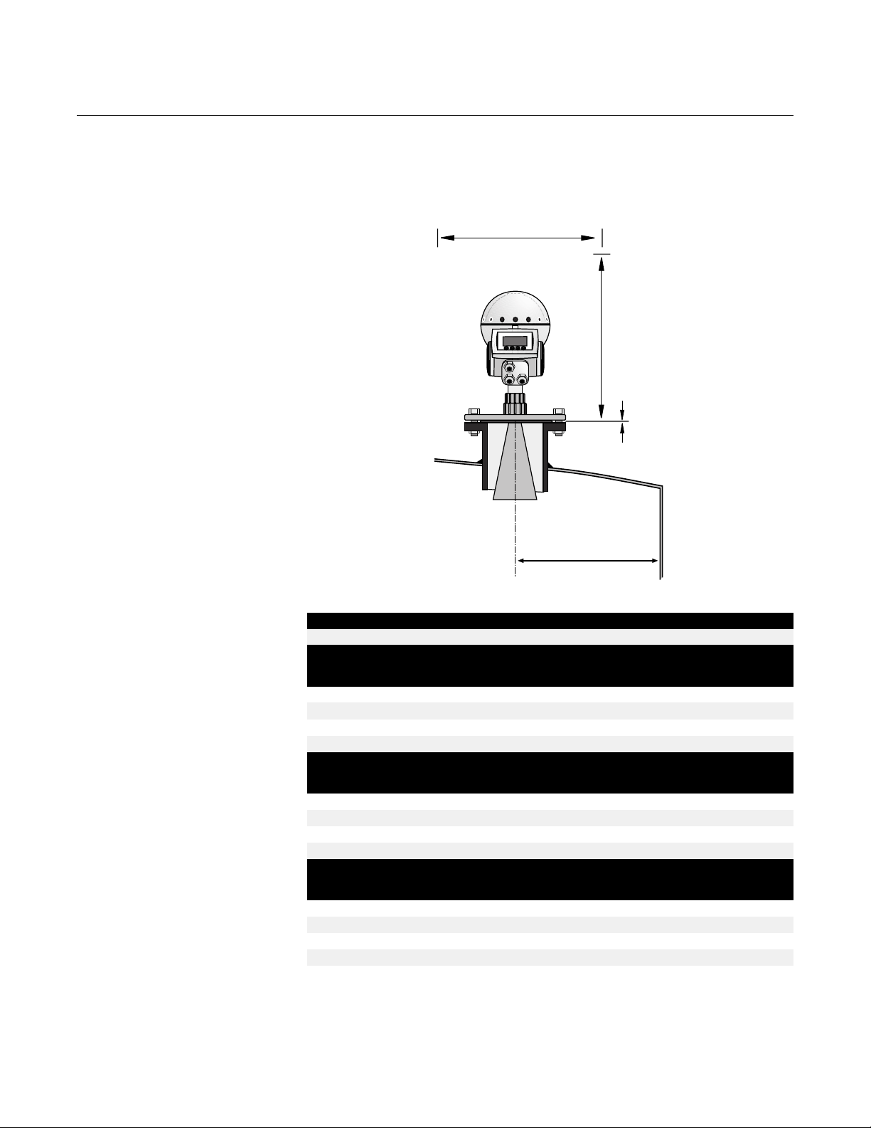
The Extended Cone antenna is suitable for tanks with long nozzles or tanks
where measurements should be avoided in the region close to the nozzle.
Use the Extended Cone antenna if:
• the nozzle is high, see Figure 2-59:
ANSI 3” antenna for nozzles higher than 9.8 in. (250 mm),
ANSI 4” antenna for nozzles higher than 11.8 in. (300 mm),
ANSI 6” antenna for nozzles higher than 15.8 in. (400 mm),
• there are disturbing objects close to the tank opening, see Figure 2-60,
or
• there is a rough surface at the inside of the nozzle or there is a height
difference between nozzle sides, see Figure 2-61.
2-40
Page 59

Rosemount 5600 Series
Figure 2-59. Example of a high
nozzle
Figure 2-60. Example of
disturbing objects close to the
tank nozzle
Reference Manual
00809-0100-4024, Rev BA
September 2005
TANK_UNDERGROUND
Figure 2-61. Examples of
problem nozzles
2-41
Rust or deposit
Height
difference
TANK_INSULATED
Bad welding
5600/ROUGH_SURFACES
Page 60

Rosemount 5600 Series
Figure 2-62. Total distance
between flange and product
level
1. Measure the total distance A between the flange and the maximum
product level.
2. The standard length of the Extended Cone antenna is 20 in. (500 mm). If
A is less than 20 inches (500mm), then the cone may be cut so these
minimum dimensions are met.
minimum 0.8 in
(20 mm)
maximum level
Reference Manual
00809-0100-4024, Rev BA
September 2005
A
15°
min. 1.2 in
(30 mm)
20,04
Due to the slanting opening of the antenna the direction of the radar beam is
slightly changed towards the short end of the antenna opening. If objects are
present which may cause disturbing radar echoes, the antenna should be
oriented in such a way that the disturbing objects do not interfere with the
radar signal. The short side should be turned away from disturbing objects on
the most open part of the tank.
2-42
Page 61

Rosemount 5600 Series
MOUNTING THE CONE
ANTENNA WITH
FLUSHING
CONNECTIONS
Figure 2-63. Cone Antenna with
Integrated Flushing Connection
Dimensions
Reference Manual
00809-0100-4024, Rev BA
September 2005
7.87 (200)
Figure 2-64. Mount the flushing
cone antenna on the nozzle
Connection for tubing
NOTE
Dimensions are in
inches (millimeters)
3.66 (93) (4 in. Cone)
5.55 (141) (6 in. Cone)
7.44 (189) (8 in. Cone)
15.75 (400)
5.12 (130) (4 in. Cone)
9.45 (240) (6 in. Cone)
13.98 (355) (8 in. Cone)
5600_PDS_MS_2C.EPS
1. The flange is a part of the antenna assembly and welded to the cone
antenna. Carefully fit the antenna assembly and appropriate gasket on
the tank nozzle.
2-43
Antenna assembly
Gasket
FLUSHING_CONE_ANTENNA
Page 62

Rosemount 5600 Series
2. Insert the wave guide tube into the upper wave guide.
Make sure the o-ring at the lower end of the wave guide tube is in place.
Figure 2-65. Insert wave guide
tube
3. Mount the transmitter head and tighten the nut. Check that the guide pins
on the adapter enter the corresponding grooves on the upper wave
guide.
Reference Manual
00809-0100-4024, Rev BA
September 2005
Upper Wave Guide
Wave guide tube
O-ring
WAVEGUIDE_TUBE
Figure 2-66. Mount the
transmitter head
Nut
Upper wave guide
Protection sleeve
Guide pins
2-44
FLUSHING_ANTENNA_HEAD
Page 63

Rosemount 5600 Series
4. Connect your tubing to the antenna for cleaning, purging, or cooling
purposes. Use a minimum 0.4 in. (10 mm) tube or pipe. Typical media to
use are:
• nitrogen,
•air,
• water, or
•steam.
Figure 2-67. Connect tubing to
antenna
Reference Manual
00809-0100-4024, Rev BA
September 2005
Connection for tubing
FLUSHING_ANTENNA_CONNECT
2-45
Page 64

Rosemount 5600 Series
Reference Manual
00809-0100-4024, Rev BA
September 2005
2-46
Page 65

Reference Manual
00809-0100-4024, Rev BA
September 2005
Rosemount 5600 Series
Section 3 Electrical Installation
Safety Messages . . . . . . . . . . . . . . . . . . . . . . . . . . . . . . . . . page 3-1
System Overview . . . . . . . . . . . . . . . . . . . . . . . . . . . . . . . . page 3-2
Cables . . . . . . . . . . . . . . . . . . . . . . . . . . . . . . . . . . . . . . . . . page 3-3
Power Supply . . . . . . . . . . . . . . . . . . . . . . . . . . . . . . . . . . . page 3-3
Grounding . . . . . . . . . . . . . . . . . . . . . . . . . . . . . . . . . . . . . . page 3-4
HART Electrical Installation . . . . . . . . . . . . . . . . . . . . . . . . page 3-4
FOUNDATION Fieldbus Electrical Installation . . . . . . . . . page 3-8
Connecting the 2210 Display Unit . . . . . . . . . . . . . . . . . . . page 3-12
SAFETY MESSAGES Procedures and instructions in this section may require special precautions to
ensure the safety of the personnel performing the operations. Information that
raises potential safety issues is indicated by a warning symbol ( ). Please
refer to the following safety messages before performing an operation
preceded by this symbol.
Explosions could result in death or serious injury:
Verify that the operating environment of the transmitter is consistent with the appropriate
hazardous locations certifications.
Before connecting a HART-based communicator in an explosive atmosphere, make sure
the instruments in the loop are installed in accordance with intrinsically safe or
non-incendive field wiring practices.
Do not remove the transmitter cover in explosive atmospheres when the circuit
is alive.
Failure to follow safe installation and servicing guidelines could result in death or
serious injury:
Make sure only qualified personnel perform the installation.
Use the equipment only as specified in this manual. Failure to do so may impair the
protection provided by the equipment.
Do not perform any service other than those contained in this manual unless you are
qualified.
High voltage that may be present on leads could cause electrical shock:
Avoid contact with leads and terminals.
Make sure the main power to the 5600 Series Radar Level Transmitter is off and the lines to
any other external power source are disconnected or not powered while wiring
the transmitter.
www.rosemount.com
Page 66

Rosemount 5600 Series
SYSTEM OVERVIEW Power Supply
Connect the power supply to terminals 3 and 4 in the non-intrinsically safe
Junction Box (EEx e).
Analog Outputs
There are two analog outputs which can be of passive or active type (external
or internal loop supply). The primary output has a HART interface.
Connect the primary analog output to terminals 1 and 2.
Use the EExe junction box for non-intrinsically safe applications, and the EExi
junction box for intrinsically safe applications.
Digital Communication
The 5600 Series Radar Level Transmitter can be equipped with HART
interface, and can be either connected EExe or EExi.
The Foundation fieldbus can be connected to either the intrinsically safe
(EExi) or the non-intrinsically safe (EExe) junction box.
Display Unit
Reference Manual
00809-0100-4024, Rev BA
September 2005
Figure 3-1. Junction boxes X1
and X2
Flame-Proof enclosure
FM: Explosion proof
Primary analog output or serial communication
Power supply (FM: conduit fitting)
Connect the intrinsically safe Rosemount 2210 Remote Display Unit to
terminals 5, 6, 7 and ground in the intrinsically safe (EExi) junction box.
Transmitter Junction Box
The standard version is equipped with two separate junction boxes, one
non-intrinsically safe and one intrinsically safe part. There is also an optional
version with two non-intrinsically safe compartments.
Connection for Display
ATEX: EEx e
CSA:
(FM: conduit fitting)
Unit, see page 3-12
ATEX: EEx i (Optional: EEx e)
FM: Intrinsically safe
(Optional: Explosion proof)
CSA:
Intrinsically safe analog outputs
(or conduit for non-IS outputs)
TH40HEAD_ED3
3-2
Page 67

Reference Manual
00809-0100-4024, Rev BA
September 2005
Figure 3-2. Schematic
illustration of the Rosemount
5600 transmitter connection
HART®
Interface
Rosemount 5600 Series
Primary Out
Non-IS
X2
7
1
2
Junction
3
Box X1
4
X1
78
9
456
123
Junction
Box X2
Optional
EEx e
6
5
4
3
2
1
X2
4
3
2
1
Level
6.767
m
78
9
456
123
1 and 2 Not used
Secondary
Output
Primary
Output IS
Secondary
Output
CABLES Depending on local requirements, cable glands, or explosion proof conduits
must be used for connection to the non-intrinsically safe junction box (EEx e).
For the connection to the instrinsically safe junction box (EEx i) use cable
glands with integral shield connection for cable diameter 6-12 mm or conduit.
Use shielded instrument cable 0.5 mm
serial communication. Use min. 0.5 mm
2
(AWG 20) for analog outputs and
2
cable for power supply.
5600-CONFIG_EXAMPLE2, 3, 4_ED3, TH40HEAD_ED3_2
POWER SUPPLY You can use either DC or AC as the built in power supply has a wide input
range. The following specification is valid for the power supply:
• 24-240 V
• DC/AC 0-60 Hz
•10 W
•15 VA
There is no voltage selector in the electronics compartment since the
transmitter power supply unit automatically adapts to the available voltage
within specified limits.
NOTE
The minimum voltage required at the transmitter power terminals is 20V.
Check that the voltage loss over the power cables is not large enough to
make the voltage drop below 20V. The maximum voltage is 265V over the
same power terminals.
3-3
Page 68

75C
HART
Rosemount 5600 Series
GROUNDING ATEX
The flameproof enclosure must be connected to a potential equalizing
network or the tank shell or according to national code of practice.
This grounding also serves as electrical safety ground. Additional connection
to the protective ground terminal of terminal X1 in Junction Box EExe is not
recommended except where required according to national code of practice.
A ground loop with circulating current may occur. See Appendix B: Product
Certifications.
Figure 3-3. Grounding
connection
Reference Manual
00809-0100-4024, Rev BA
September 2005
D
O
N
E
N
S
P
O
F
A
E
T
O
R
S
E
O
O
N
H
P
U
O
P
I
E
V
S
T
N
I
R
O
N
I
W
R
M
G
I
H
T
S
A
E
T
O
N
N
S
U
E
U
S
E
V
O
N
T
E
D
E
E
R
R
N
R
P
A
S
G
Z
I
O
O
I
A
Z
N
H
T
E
.
D
.
HART ELECTRICAL
INSTALLATION
External Connections
Figure 3-4. Transmitter Terminal
Block (Non-IS Wiring)
5600-GROUNDING
FM
Grounding is accomplished through the conduit pipes.
Non-Intrinsically Safe Junction Box - EEx e
This Junction Box is for non-intrinsically safe connections and power supply.
A
75C
1
2
X1
1
+4-20mA
3
or Bus
4
2
-4-20mA
or Bus
3
Power
N/L1/+
4
Power
L/L2/-
X1
5600_JB_EEXE
3-4
Page 69

Reference Manual
75C
00809-0100-4024, Rev BA
September 2005
Rosemount 5600 Series
1-2 Non-intrinsically safe HART/4-20 mA primary analog output or
non-intrinsically safe F
3-4 Power supply input
A Electrical safety ground terminal
OUNDATION fieldbus.
Figure 3-5. Transmitter Terminal
Block (IS Wiring)
NOTE:
Redundant when the transmitter is grounded according to ATEX.
Cable shield
Connect the shield to the cable glands.
If conduit fittings are used no cable shield is used.
Intrinsically Safe Junction Box - EEx i
This Junction Box is for intrinsically safe connections and for connection of
the Display Unit.
A
X1
X2
75C
1
7
6
5
4
3
2
DP/DB
DP/DA
DP +
SO -
SO +
PO -
X2
PO +
HART
5600_JB_EEXI
1-2 Intrinsically safe HART/4-20 mA primary analog output or intrinsically
OUNDATION fieldbus
safe F
3-4 Secondary analog output
5-7 Display Unit (6-7 also used for Sensor Bus see “Configuration Using the
Sensor Bus Port” on page 6-16)
A Ground terminal for Display Unit
Cable shield
Connect the shield to the cable glands.
If conduit fittings are used no cable shield is used.
3-5
Page 70

75C
HART
Rosemount 5600 Series
Optional Non-intrinsically Safe Junction Box
This is the standard intrinsically safe Junction Box (EExi) fitted with an
alternative connector for connection of non-IS output if required.
Figure 3-6. Alternative
Non-intrinsically safe junction
box
1-2 Not used
3-4 Non-intrinsically safe Secondary Analog Output
A Ground terminal (not used)
EEx e
Reference Manual
00809-0100-4024, Rev BA
September 2005
75C
X2
NOT
USED
1
NOT
USED
2
4
SO +
3
3
2
1
SO -
4
A
5600-JB_EEXIE, TH40HEAD_ED4
Connecting HART
devices
Figure 3-7. Typical hand-held
communicator active output
(primary)
Cable shield
Connect the shield to the cable glands.
If conduit fittings are used no cable shield is used.
Active output (internal loop supply)
For transmitters with active output a hand-held terminal or a HART modem
can be connected as follows:
Junction Box
EEx e
Input Impedance
< 300 Ohm
1
2
3
4
X1
24-240 V
DC/AC 0-60 Hz
10 W
15 VA
5600-ANALOGOUT_ACTIVE_ED3
3-6
Page 71

Reference Manual
00809-0100-4024, Rev BA
September 2005
Figure 3-8. Typical hand-held
Communicator (passive output)
Rosemount 5600 Series
Passive output (external loop supply)
A hand-held terminal or a HART modem should not be connected directly
across an external power supply. Instead, it should be connected across a
load resistor of about 250 ohms.
Junction Box
EEx e
1
2
3
4
X1
Voltage compliance
7-30 V
V
s
250
HART
Figure 3-9. Typical hand-held
Communicator connection in
intrinsically safe conditions
24-240 V
DC/AC 0-60 Hz
10 W
15 VA
5600-ANALOGOUT_PASSIVE_V2_ED3
Intrinsically safe conditions
A hand-held intrinsically safe communicator can be connected in the
hazardous area. The HART interface must be connected via a zener barrier in
the safe area. It is also possible to use an intrinsically safe Ex classed HART
interface which has a built in Zener barrier.
Rosemount
5600
Zener
barrier
HART
Interface
Analog instrument
and/or DCS system
Hand Held
Intrinsically Safe
Communicator
5600-HART_IS_EXNONEX
3-7
Page 72

Rosemount 5600 Series
Figure 3-10. Typical Hand-held
Communicator connection in
Non-intrinsically safe conditions
FOUNDATION Fieldbus
Non-Intrinsically safe conditions
Rosemount
5600
Hand Held
Communicator
Reference Manual
00809-0100-4024, Rev BA
September 2005
HART
Interface
Analog instrument
and/or DCS system
FOUNDATION FIELDBUS
ELECTRICAL
INSTALLATION
Power Supply
5600-HART_NONIS_EXNONEX
The transmitter requires separate power within the range 24-240 V AC or DC
0-60Hz. Tighten the terminal screws to ensure adequate contact. See “Power
Supply” on page 3-3 and Figure 3-18 on page 3-14 for additional information.
Fieldbus Voltage limits: 9 to 32 V
Current Draw: 12.5 mA
For I.S. Applications:
< 30 V
U
i
< 300 mA
I
i
< 1.3 W
P
i
= 0 μF
C
i
= 0 mH
L
i
3-8
Page 73

Reference Manual
75C
00809-0100-4024, Rev BA
September 2005
Rosemount 5600 Series
Fieldbus Connections For best installation practices use a fieldbus type A cable. Do not run
unshielded signal wiring in conduit or open trays with power wiring or near
heavy electrical equipment. Do not remove the transmitter cover in explosive
atmospheres when the circuit is alive. Use ordinary copper wire of sufficient
size to ensure that the voltage across the fieldbus terminals does not go below 9
V dc.
NOTE
Do not apply high voltage (e.g. ac line voltage) to the fieldbus terminals.
Abnormally high voltage can damage the unit.
Model Code Use the Model Code located on your fieldbus transmitter to determine wiring
connection.
Figure 3-11. Example of a
fieldbus label
5601 UE5P7A0NE
Fieldbus
OUNDATION
F
External Connections Non-Intrinsically Safe Wiring
Figure 3-12. Transmitter
Terminal Block (Non-IS Wiring)
A
NOTE:
1-2= BUS Connection
3-4 =Power Connections
A= Ground Terminal
5600/LABELS/FIELDBUSLABEL_02A,_02B.EPS
75C
1
X1
2
1
+4-20mA
3
or Bus
4
2
-4-20mA
or Bus
3
Power
N/L1/+
4
Power
L/L2/-
X1
5600_JB_EEXE
3-9
Page 74

Rosemount 5600 Series
75C
1. Connect fieldbus wires to terminal 1 and 2 on the X1 side. These
terminals are marked BUS terminals. The BUS terminals are polarity
insensitive.
2. Connect the power wires to terminal 3 and 4 on the X1 side. These wires
are separate from the fieldbus wires.
Intrinsically Safe Wiring
Reference Manual
00809-0100-4024, Rev BA
September 2005
FOUNDATION Fieldbus
Figure 3-13. Transmitter
Terminal Block (IS Wiring)
Hazardous Locations Refer to Appendix B: Product Certifications.
NOTE:
1-2= BUS Connection
A
X1
X2
75C
7
6
5
4
3
2
1
X2
PO +
PO -
SO +
SO -
DP +
DP/DA
DP/DB
3-4 = Secondary Analog
output
5-7 = Display Unit (Optional)
A= Ground Terminal for
Display Panel
5600_JB_EEXI
1. Connect fieldbus wires to terminals 1 and 2 on the X2 side. These
terminals are marked BUS terminals. The BUS terminals are polarity
insensitive.
2. Connect the power wires to terminal 3 and 4 on the X1 side. These wires
are separate from the fieldbus wires.
NOTE
Do not ground out the live signal wiring to the housing when working on a
segment. Grounding the communication wires may result in temporary loss of
communication with all devices on the segment.
Grounding Signal wiring of the fieldbus segment can not be grounded. Grounding out
one of the signal wires will shut down the entire fieldbus segment.
Shield Wire Ground
To protect the fieldbus segment from noise, grounding techniques for shield
wire usually require a single grounding point for shield wire to avoid creating a
ground loop. The ground point is typically at the power supply.
3-10
Page 75

Reference Manual
00809-0100-4024, Rev BA
September 2005
Connecting fieldbus
devices
Figure 3-14. Rosemount 5600
Radar Transmitter Field Wiring
Integrated Power
Conditioner
and Filter
Power
Supply
(The power supply,
filter, first
terminator, and
configuration tool
are typically located
in the control room.)
Rosemount 5600 Series
OUNDATION
F
fieldbus
Configuration
Tool
6234 ft (1900 m) max
(depending upon cable
characteristics)
Terminators
Fieldbus
Segment
(Trunk)
(Spur)
(Spur)
Signal
Wiring
FOUNDATION Fieldbus
*Intrinsically safe installations
may allow fewer devices per I.S.
barrier due to current
limitations.
fieldbus
devices on
segment
5600_01A
Configuration with Radar Master
(in a fieldbus system hooked up to
the device Sensor Bus Port).
3-11
Page 76

Rosemount 5600 Series
Reference Manual
00809-0100-4024, Rev BA
September 2005
CONNECTING THE 2210
DISPLAY UNIT
Figure 3-15. Rosemount 2210
Display Unit Connection
2210 Display Unit
The Rosemount 2210 Display Unit can be factory mounted on the 5600
Series Radar Level Transmitter enclosure or remotely mounted. The Display
Unit can be used for configuration of the transmitter as well as for displaying
tank data (see Section 7: 2210 Display Unit Configuration for information on
how to operate the transmitter by using the Display Unit).
5600-PRO_RDU40, RDU40
3-12
Page 77

Reference Manual
75C
00809-0100-4024, Rev BA
September 2005
Figure 3-16. Intrinsically safe
junction box
Rosemount 5600 Series
The Display Unit is connected to the Intrinsically Safe Junction Box on the
front of the transmitter head:
A
Intrinsically
Safe Junction
Box (EEX i)
75C
2
1
7
6
5
4
3
DP/DB
DP/DA
DP +
SO -
SO +
PO -
X2
PO +
The Display Unit is offered in three versions:
• Mounted on the transmitter
• Remote mounted up to 330 ft (100m)
• Remote mounted with Temperature option card in it. This card allows
for up to 6 temperature sensors to be hooked up. See “Temperature
Measurement” on page 3-14 for temperature connections.
Connect the Display Unit to the X2 terminal in the Intrinsically Safe Junction
Box by the following four wires:
• Grounding wire to the ground terminal
• Signal wires to terminal 6 and 7
• Supply voltage to terminal 5
5600-TH40HEAD_ED3, JB_EEXI_01AA.EPS
2210 Display Unit
Figure 3-17. Connection of
junction box with and without
temperature option
IS Ground
DP DB
DP DA
+
DP
Transmitter Head
Intrinsically Safe
Junction Box (EEx i)
X2
7
6
5
4
3
2
1
X12:4 (Black)
X12:3 (Grey)
X12:2 (Blue)
X12:1 (Red)
12345678
12345678
X11
1
2
3
4
X12
1234
with
temperature
option
1234
X11
X12
1234
without
temperature
option
5600-RDU40_X12_TH_X2
3-13
Page 78

Rosemount 5600 Series
Connecting the Rosemount 2210 Display Unit
1. For power supply connect a wire between terminal block X2, position 5
and terminal block X12, position 1.
2. For communication connect a wire between terminal block X2, position 6
and terminal block X12, position 2, and a wire between terminal block X2
position 7 and terminal block X12 position 3.
3. Finally for grounding connect a wire from the IS Ground screw in the X2
terminal compartment to terminal block X12 position 4.
Reference Manual
00809-0100-4024, Rev BA
September 2005
Temperature
Measurement
Figure 3-18. Overview of the
TP40 board
2210 Display Unit
For temperature measurements you can use 1-3 3-wire RTD spot elements or
1-6 3-wire RTDs with common return. The sensors are connected to nozzle
X17 and X18 on the optional TP40 board. Depending on the type of sensor
that is used, different jumpers must be set on nozzles X24, X25, X26, X27
and X28, see Figure 3-18, Figure 3-19, and Figure 3-20.
Closed
X17
X25
1
2
3
4
X11
X12
1234
A
B
C
12345678
12345678
X18
Open
X24
X26
X28
X27
C
B
A
Position 2
Position 1
RDU40_TP40
3-14
Page 79

Reference Manual
00809-0100-4024, Rev BA
September 2005
Figure 3-19. Connecting the
sensors - Spot Elements
Rosemount 5600 Series
Spot elements 3-wire independent
X17:2 (Red)
X17:3 (White)
X17:4 (White)
X17:6 (Red)
X17:7 (White)
X17:8 (White)
X18:2 (Red)
X18:3 (White)
Figure 3-20. Connecting the
Sensors - Multiple Spot
Elements
X18:4 (White)
Jumper Settings
X24 A, B, C open
X25 A, B, C closed
X26 position 1
X27 position 1
X28 position 1
Multiple spot elements 3-wire common return
X17:2 (Brown)
X17:6 (Red)
X18:2 (Orange)
X18:5 (Yellow)
X18:6 (Green)
X18:7 (Blue)
5600-RDU40_TP40
2210 Display Unit
Jumper Settings
X24 A, B, C closed
X25 A, B, C closed
X26 position 2
X27 position 2
X28 position 2
X18:8 (Black)
X17:4 (Black)
5600-RDU40_TP40
3-15
Page 80

Rosemount 5600 Series
Reference Manual
00809-0100-4024, Rev BA
September 2005
3-16
Page 81

Reference Manual
00809-0100-4024, Rev BA
September 2005
Rosemount 5600 Series
Section 4 Configuration
Antenna . . . . . . . . . . . . . . . . . . . . . . . . . . . . . . . . . . . . . . . . page 4-3
Tank Geometry . . . . . . . . . . . . . . . . . . . . . . . . . . . . . . . . . . page 4-5
Analog Output . . . . . . . . . . . . . . . . . . . . . . . . . . . . . . . . . . . page 4-7
Process Conditions . . . . . . . . . . . . . . . . . . . . . . . . . . . . . . page 4-9
Temperature Measurement . . . . . . . . . . . . . . . . . . . . . . . . page 4-9
Volume Calculation . . . . . . . . . . . . . . . . . . . . . . . . . . . . . . . page 4-10
Advanced Functions . . . . . . . . . . . . . . . . . . . . . . . . . . . . . page 4-11
Safety Messages Procedures and instructions in this section may require special precautions to
ensure the safety of the personnel performing the operations. Information that
raises potential safety issues is indicated by a warning symbol ( ). Please
refer to the following safety messages before performing an operation
preceded by this symbol.
Explosions could result in death or serious injury:
Verify that the operating environment of the transmitter is consistent with the appropriate
hazardous locations certifications.
Before connecting a HART-based communicator in an explosive atmosphere, make sure
the instruments in the loop are installed in accordance with intrinsically safe or
non-incendive field wiring practices.
Do not remove the transmitter cover in explosive atmospheres when the circuit
is alive.
www.rosemount.com
Page 82

Reference Manual
00809-0100-4024, Rev BA
Rosemount 5600 Series
September 2005
OVERVIEW To be able to fully utilize the 5600 Radar Level transmitter it has to be properly
configured. To configure the transmitter access the configuration parameters
and assign them appropriate values. In this section you will find the
parameters used and how they affect your application. The preferred user
interface for the configuration is the Rosemount Radar Master software. See
“Safety Messages” on page 5-1. Configuration can also be performed using
the:
• AMS / 375 Field Communicator (see Section 5: HART Configuration)
• Foundation Fieldbus (see Section 6: FOUNDATION Fieldbus
Configuration)
• 2210 Display Unit (see Section 7: 2210 Display Unit Configuration)
• DeltaV (see Section 6: FOUNDATION Fieldbus Configuration)
• or others
Limited support for various configuration parameters may apply when using
certain configuration tools.
Basic Configuration The parameters are divided into several categories listed below. Configuration
includes specification of parameters for:
• “Antenna” on page 4-3
• “Tank Geometry” on page 4-5
• “Analog Output” on page 4-7
• “Process Conditions” on page 4-9
• “Temperature Measurement” on page 4-9
• “Volume Calculation” on page 4-10
Advanced Configuration When the basic configuration is done the transmitter will be optimized for your
application. However, in some cases the transmitter must be further
configured using the Advanced Functions (this may affect the previous basic
configuration by updating some parameters already set).
• “Advanced Functions” on page 4-11
4-2
Page 83

Reference Manual
00809-0100-4024, Rev BA
September 2005
Rosemount 5600 Series
ANTENNA For the antenna a few choices are available. The type of antenna must always
be selected and, if applicable, corresponding type of tank sealing to be used.
User Defined is for non-standard antennas only.
The following parameters are used:
Hold Off Distance The (UNZ) defines how close to the transmitter’s reference point a
Pipe Inner Diameter The figure is used to compensate for the lower microwave
Tank Connection Length The (TCL) parameter is entered for antenna type User Defined
level value is accepted. Normally, the Hold Off Distance is set
automatically and does not need to be changed. However, if there
are disturbing echoes in the upper part of the tank, for example
from the tank nozzle, you can increase the Hold Off Distance in
order to avoid measurements in the region close to the antenna.
(See “Setting the Hold Off Distance” on page 2-39).
Hold Off
Distance (UNZ)
5600/HOLDOFF DISTANCE.TIF
propagation speed inside the pipe. An incorrect value will give a
scale factor error. Only valid for pipe antennas or cone antennas in
existing still-pipe. If locally supplied still-pipes are used, make sure
the inner diameter is noted before installation of the pipe.
only. For standard antennas the TCL value is set automatically. For
the 500 mm extended cone use the TCL
(See “Setting the Tank Connection Length (TCL)” on page 2-38).
values in Table 4-2.
ext
4-3
Page 84

Rosemount 5600 Series
Table 4-1. Hold Off Distance Default Value inches (millimeters)
Pipe with Cone PTFE 18.70 (475) 2.36 (60)
Pipe with Cone Quartz 20.28 (515) 2.36 (60)
Process Seal 4” PTFE 22.17 (563) 7.87 (200)
Process Seal 6” PTFE 24.53 (623) 7.87 (200)
Table 4-2. TCL
PTFE 0.019 (0.489) 1.90 (0.482) 1.88 (0.477)
Quartz 2.08 (0.529) 2.06 (0.522) 2.04 (0.517)
Reference Manual
00809-0100-4024, Rev BA
September 2005
Antenna Type TCL Hold Off
User Defined 0.000 (0.000) 0.000 (0.000)
Rod 100 23.62 (600) 23.43 (595)
Rod 250 30.83 (780) 29.06 (738)
Cone 3” PTFE 18.70 (475) 4.72 (120)
Cone 4” PTFE 18.70 (475) 6.69 (170)
Cone 6” PTFE 18.70 (475) 11. 0 2 (28 0 )
Cone 8” PTFE 18.70 (475) 15.75 (400)
Cone 3” Quartz 20.28 (515) 4.72 (120)
Cone 4” Quartz 20.28 (515) 6.69 (170)
Cone 6” Quartz 20.28 (515) 11 .02 ( 2 80)
Cone 8” Quartz 20.28 (515) 15.75 (400)
Parabolic 31.22 (793) 7.87 (200)
, for standard extended lengths, 500 mm
ext
Sealing 3 inch Cone 4 inch Cone 6 inch Cone
4-4
Page 85

Reference Manual
00809-0100-4024, Rev BA
September 2005
Rosemount 5600 Series
TANK GEOMETRY For Tank Geometry the following basic configuration must be performed:
Tank Height (R) The Tank Height is defined as the distance between the upper
Tank Type
Tank Bottom Type
reference point (top-side of the tank nozzle) and the lower
reference point (zero level).
Transmitter’s
Reference Point
Tank Height (R)
Zero Level
By defining Tank Type and Tank Bottom Type default values for
some parameters are set. Through this the transmitter is optimized
for a specific combination of Tank type and Tank Bottom Type. For
tank types vertical cylinder and cubical, all tank bottom types are
valid. For tank types horizontal cylinder and spherical, the
parameter Tank Bottom Type is not used.
Select Tank Bottom Type flat inclined if the bottom inclination is
between 10 and 30 degrees. If the inclination is less than 10
degrees but there are disturbing objects on the tank floor (like
heating coils) right beneath the transmitter use this selection.
The following combinations of Tank Type and Tank Bottom Type are valid:
Table 4-3. Tank Bottom
Tank Type Tank Bottom Type
Vertical Cylinder Flat, Dome, Cone, Flat inclined
Horizontal Cylinder Not Applicable
Spherical Not Applicable
Cubical Flat, Dome, Cone, Flat inclined
Flat
Dome
Flat Inclined
Cone
Spherical
Spherical
5600_C_01A.EPS
4-5
Page 86

Rosemount 5600 Series
Reference Manual
00809-0100-4024, Rev BA
September 2005
Advanced Tank
Geometry Configuration
Advanced configuration is done through the following parameters:
Distance Offset (G) The Distance Offset (G) is defined as the distance between the
Minimum Level Offset (C) The Minimum Level Offset (C) defines a lower null zone which
Calibration Distance The Calibration Distance is by default set to zero. It is used to
Show Negative Values as
Zero
upper reference point and the flange (the flange is referred to as
the Transmitter’s Reference Point). You can use the Distance
Offset to specify your own reference point at the top of the tank.
Set the Distance Offset to zero if you want the flange as upper
reference point. The Distance Offset is defined as positive if you
use an upper reference point above the Transmitter’s Reference
Point. The Distance Offset is used when the measured level by the
transmitter should correspond with the level value obtained by
hand-dipping.
extends the measurement range beyond the Zero Level Reference
Point down to the tank bottom. The Minimum Level Offset is
defined as the distance between the zero level (Tank Level
Reference Point) and the minimum accepted level and tank
bottom. Set the Minimum Level Offset to zero if you use the tank
bottom as zero level reference point. If the zero level is not defined
as the tank bottom and instead is an elevated point as the datum
plate, you need to define the Minimum Level Offset.
Note: The Minimum Level Offset can not be negative.
adjust the transmitter so that measured levels match hand dipped
product levels. Normally a minor adjustment is necessary. There
may for example be a deviation between the actual tank height and
the value stored in the transmitter database.
Set this parameter if you want levels below the reference point at
the bottom of the tank to be displayed as zero. This parameter can
be used if you have set a Minimum Level Offset distance in the
tank geometry configuration.
Tank Height (R)
Minimum Level
Offset (C)
Distance Offset (G)
Transmitter’s
Reference Point
Hold Off
Distance (UNZ)
5600/SCREEN DUMPS/11GEOMETRYADVANCED.TIF
4-6
Page 87

Reference Manual
00809-0100-4024, Rev BA
September 2005
Rosemount 5600 Series
ANALOG OUTPUT The 5600 has the possibility to handle two analog outputs which can be
separately configured.
However, if your transmitter is equipped with a primary 4-20 mA HART output,
you must use Analog Output 1. (Analog Output 1 is not available for primary
output when using other bus communication protocols than HART).
Output Source Select the source to control the analog output.
Upper Range Value
Lower Range Value
Alarm Mode Choose the desired Alarm Mode. The Alarm Mode specifies the
Disable Limit Alarm if Out
of Range
Enter the range values that correspond to the analog output values
4 and 20 mA. You can specify any values as long as the Upper
Range Value is above the Lower Range Value. If the measured
value goes beyond the measurement range, the transmitter enters
the alarm mode.
analog output state when a measurement error occurs or when the
measured value is out of range.
High: the output current is set to 22 mA.
Low: the output current is set to 3.8 mA.
Freeze Current: the output current is set to the present value at the
time when the error occurs.
Binary High: the output current is 4 mA under normal conditions. If
there is a measurement error, or when the source signal is out of
range, the output current is set to 20 mA.
Binary Low: the output current is 20 mA under normal conditions. If
there is a measurement error, or when the source signal is out of
range, the output current is set to 4 mA.
If the detected limit is out side the upper or lower limit, setting this
parameter suppresses the analog output from going into alarm
mode.
4-7
Page 88

Rosemount 5600 Series
Figure 4-1 illustrates how the analog output signal is related to the actual
measured product level and the specified upper and lower limits. As
illustrated, if the source signal exceeds the Upper limit or falls below the
Lower limit, the output current is set according to the specified Alarm Mode
settings.
If your transmitter is equipped with an optional analog output
(Analog Output 2), configure it as described above.
Figure 4-1. Alarm Mode Settings
Level
Upper
Lower
Analog
Output
20 mA
4 mA
3.8 mA
Analog
Output
22 mA
20 mA
Reference Manual
00809-0100-4024, Rev BA
September 2005
Product Level
Time
Alarm Mode
Low Current
Time
Alarm Mode
High Current
4 mA
Analog
Output
20 mA
4 mA
Analog
Output
20 mA
4 mA
Analog
Output
20 mA
4 mA
Time
Time
Time
Time
Alarm Mode
Freeze Current
Alarm Mode
Binary High
Alarm Mode
Binary Low
5600_C_02A.EPS
Analog Output current as a function of product level for different alarm mode
settings. The shaded area indicates analog output in Alarm mode. The graphs
are valid when Disable Limit Alarm if Out of Range is not set.
4-8
Page 89

Reference Manual
00809-0100-4024, Rev BA
September 2005
Rosemount 5600 Series
PROCESS CONDITIONS Describe the conditions in your tank according to the Process Conditions
listed below. For best performance choose only if applicable and not more
than two options.
TEMPERATURE
MEASUREMENT
Rapid level changes Optimize the transmitter for measurement conditions where the
Turbulent Surface This parameter should be used if the tank shows a turbulent
Foam Setting this parameter optimizes the transmitter for conditions
Solid Products Setting this parameter optimizes the transmitter for solid
level changes quickly due to filling and emptying of the tank. A
standard configured transmitter is able to track level changes of
up to 4 inch/s (100 mm/s). When the Rapid Level Changes
check box is marked, the transmitter can track level changes of
up to 8 inch/s (200 mm/s).
surface. The reason for the turbulence might be splash loading,
agitators, mixers, or boiling product. Normally the waves in a
tank are quite small and cause local rapid level changes. By
setting this parameter the performance of the transmitter will be
improved when there are small and quickly changing
amplitudes and levels.
with weak and varying surface echo amplitudes, which are
typical for foam.
products, for example concrete or grains, which are not
transparent for radar signals. For instance, this parameter can
be used when the application is a silo with product buildup.
Up to six temperature sensors can be connected to the 2210 Display Unit.
You can use 1-3 spot elements or 1-6 multiple spot elements. All temperature
sensors must be of the same type, for example, the Pt100 or CU90. See
“Temperature Measurement” on page 3-14 for information on how to connect
the temperature sensors.
Use one of the following temperature measurement conversion methods:
• PT100
• CU90
• User Defined Linearization Table. The sensor characteristics are
specified in a table of corresponding resistance and temperature
values.
• User Defined Formula. The sensor characteristics are specified in a
mathematical formula: R=R
at temperature T, R
is the resistance at zero degrees Centigrade and
0
*(1+A*T+B*T2) where R is the resistance
0
A and B are constants.
Sensor Mounting Level 1-6 Enter the level (from the tank bottom) at which each sensor is
mounted. The first sensor should be mounted in the lowest
position in the tank, the second above the first and so on.
Number of Sensors Enter the number of temperature sensors connected to the
Display Unit. You can have up to six sensors connected. If you
choose zero sensors temperature measurement is disabled.
4-9
Page 90

Reference Manual
00809-0100-4024, Rev BA
Rosemount 5600 Series
September 2005
VOLUME CALCULATION The Volume Calculation is performed by using one of two methods:
predefined tank shape or strapping table. The strapping table is an optional
function. If this function is required, please contact your local Rosemount
representative.
To configure the 5600 transmitter for volume calculations you have to choose
a Volume Calculation method.
Select one of the volume calculation methods. Choose one of the ideal tank
shape options if approximation of your tank with an ideal tank shape provides
sufficient accuracy. The strapping table option can be used for an arbitrary
tank shape. You can enter levels and corresponding volumes to obtain a close
match between the actual and the calculated volume. This option should be
used in cases where the tank shape deviates significantly from an ideal
sphere or cylinder, or when you require high accuracy.
NOTE
The transmitter is delivered with a code that enables the ordered software
options including strapping table volume calculation. If you wish to change the
set of available options, contact your local Rosemount representative.
Ideal Tank
Use this option if approximation of your tank with an ideal tank shape
(assuming no dished ends) provides sufficient accuracy. Enter the following
parameters:
• Tank Diameter (and the length if it is a horizontal tank).
• Volume Offset: Use this parameter if you do not want zero volume and
zero level to match (for example if you want to include volume below
the zero level).
Strapping Table
• Enter levels and corresponding volumes starting at the bottom of the
tank. These figures can typically be obtained from tank drawings or
from certificate from the tank manufacturer. If the level//volume table is
based on a reference point that is different from your reference point,
you can use Level Offset and Volume Offset. The Volume Offset is
added to every value in the corresponding column.
• Select which interpolation method to use for calculating volumes
between the strapping points. Normally, linear interpolation is the
preferred method. For spherical tanks, quadratic interpolation may
result in a smaller error. By using linear interpolation and a sufficient
number of values in the strapping table, the interpolation error can
normally be reduced to a minimum.
4-10
Page 91

Reference Manual
00809-0100-4024, Rev BA
September 2005
Rosemount 5600 Series
ADVANCED FUNCTIONS In some cases the transmitter must be further configured using the Advanced
Functions. Please note this may affect the previous basic configuration by
updating some parameters already set.
Disturbance Echo
Handling
Figure 4-2. Disturbance Echoes
There are three methods available for Disturbance Echo Handling:
• General Amplitude Threshold
• Customized Noise Threshold Table
(Amplitude Threshold Points [ATP] table)
• Registration of False Echoes
There are guidelines on when to register a false echo and what the Auto
Configuration does.
Disturbing objects
Echo from
disturbing objects
Surface echo
Surface
5600_C_03A.EPS
The False Echo function is used to improve the performance of the transmitter
when the surface is close to a horizontal surface of a stationary object in the
tank. The object causes an echo when it is above the surface. When the
echoes from the surface and the object are close to each other, they might
interfere and cause a decrease in performance.
It is possible to store the positions of the disturbing objects in the memory of
the transmitter. When the surface is passing by a disturbing object, the
transmitter can measure with a higher reliability, when the position of the
object is registered.
Use a spectrum plot to find the disturbance echoes. Remember to update it
several times to get the whole picture of disturbance echoes in the tank. Do
not base the false echo registration on only one updated spectrum plot. (See
Figure 4-3).
4-11
Page 92

Rosemount 5600 Series
200
400
600
800
1000
1200
1400
1600
1800
2000
0
0
1.0
4.0
5.0
6.0
7.0
8.0
9.0
10.0
P2 Unknown
2.0
3.0
Figure 4-3. Spectrum plot for
typical calm conditions
2000
1800
1600
1400
1200
1000
800
600
400
200
Reference Manual
00809-0100-4024, Rev BA
September 2005
C
B
P2 Unknown
D
A
1.0
2.0
3.0
A: General amplitude threshold
B: Amplitude threshold point (ATP)
C: Hold off distance (UNZ)
D: Echo curve
General
Amplitude
Threshold
Echoes with amplitudes below the general amplitude threshold will be
disregarded. Recommended threshold values are:
• Calm conditions: no turbulence, foam or condensation. Set amplitude
threshold to approximately 20% of surface echo amplitude.
• Foam, agitators, or low product DC: the surface echo signal may drop to
200-300 mV during processing in tank. A threshold value of about 150
mV is recommended.
Note:
These figures are estimations. Significantly different figures may have to be
used in many cases.
Some further considerations are:
• If water test is performed before the product enters the tank, there is
probably a difference in signal amplitude between the water and the
product. Use the signal amplitude for the product to set the amplitude
threshold.
• A moving surface may cause a decrease in signal amplitude.
4.0
5.0
6.0
7.0
8.0
9.0
10.0
56005600_08_AA.EPS
4-12
Page 93

Reference Manual
00809-0100-4024, Rev BA
September 2005
Rosemount 5600 Series
Customized
Noise
Threshold
Table
(ATP-table)
Registration of
False Echoes
You can filter out weak disturbing echoes by creating a noise threshold table.
This technique should only be use in special situations, for example at the
bottom of tanks with weak disturbing echoes. In such tanks the transmitter
may lock at disturbances close to the bottom when the tank is empty. Setting
up a noise threshold in the region will guarantee that the transmitter starts
following the surface when the tank is filled again. Make sure the surface
echo amplitude in the bottom region is always stronger than the noise
threshold. (See Figure 4-4)
Also, this function can be used in areas where occasionally there are strong
echoes present. For those large areas registering a False Echo may not be
sufficient.
Furthermore, the ATP-table can be used to remove influence for the tank
nozzle or a still-pipe inlet at the top of the tank. The Hold Off Distance (UNZ)
can also be used to manage such cases.
Do not create noise thresholds around echoes which are already registered
as interfering echoes. The general amplitude threshold is the lower limit of
the noise threshold table. (See Figure 4-4).
The False Echo function allows you to let the transmitter register disturbing
echoes caused by objects in the tank. This makes it possible to detect a
product surface close to a disturbance echo even if the surface echo is
weaker than the disturbing echo. (See Figure 4-5).
When should I register?
See the following recommendations before you register new interfering
echoes:
• Make sure that a correct amplitude threshold is set before you register
any disturbance echoes. See description of the SpectraThreshold
window.
• Keep the number of registered echoes to a minimum.
• Compare the list of interfering echoes with the tank drawing or by visible
inspection of the tank. Note if there are objects like beams, heating coils,
agitators, etc. which correspond to the found echoes. Only register
echoes which can be clearly identified as objects in the tank.
• Make sure that the level is stable before you register a disturbance echo.
A fluctuating level may indicate a temporary disturbance which is not due
to an interfering object.
• Do not register a disturbance echo if the amplitude is significantly smaller
than the amplitude of the surface echo when the surface is at the same
level as the disturbance. (In some cases weak disturbance echoes can
be filtered out by creating a noise threshold table.
• It may be necessary to register new disturbance echoes at a later stage
when objects have become visible due to surface movement.
Figure 4-4. Noise threshold
5600_C_05A.EPS
4-13
Page 94

Rosemount 5600 Series
Figure 4-5. False Echoes
Registered
Disturbance
Bottom Echo Handling
Reference Manual
00809-0100-4024, Rev BA
September 2005
Echo
5600_03_AA.EPS
Bottom Echo Visible This parameter is automatically set depending on tank type and
tank bottom type. By setting this parameter the bottom echo will
be treated as a disturbance echo to facilitate tracking of weak
surface echoes close to the tank bottom. If this parameter is not
set searching for a lost surface echo is restricted to a region
close to the tank bottom. Only set this parameter if the bottom
echo is visible
The figure shows scenarios (checked tanks) where the bottom
echo is visible. Always check if the transmitter shows a value
for the bottom at empty tank before marking the checkbox. Only
flat bottom tanks have checkbox marked as default. Set this
parameter in Advanced Service.
If Empty Tank Handling is set to automatic, the choice of Tank
Bottom Type controls the setting of Bottom Echo Visible. For
Tank Bottom Type flat, the Bottom Echo Visible parameter is
always set.
If the Empty tank Handling function is not set to automatic, the
Bottom Echo Visible parameter is set manually for all tank
types. However, the Tank Bottom Type flat always has Bottom
Echo Visible set.
5600_C_06A.EPS
4-14
Invalid Level Alarm Is Not
Set If Tank Is Empty
If the surface echo is lost close to the bottom of the tank, setting
this parameter suppresses the “invalid” display.
Page 95

Reference Manual
00809-0100-4024, Rev BA
September 2005
Full Tank Handling
Rosemount 5600 Series
Empty Tank Handling
Invalid Level Alarm Is Not
Set If Tank Is Full
Empty Tank Detection Area The Empty Tank Handling is a function for handling situations
If the surface echo is lost close to the top of the tank, the level
value will normally be displayed as “invalid”. Set this parameter
to suppress the “invalid” display.
Note
By setting this parameter the analog output will not enter alarm
mode for invalid levels close to the tank bottom or close to the
antenna.
when the surface echo is lost close to the bottom. If the surface
echo is lost the function makes the transmitter present a
zero-level measurement, and an alarm is created, unless this
alarm has been blocked.
This function is activated by default if you have selected one of
the following Tank Bottom Types: Cone, Dome, Flat Inclined, or
Unknown. This function also requires that the Bottom Echo
Visible checkbox is not marked. If it is marked the function is
disabled.
The transmitter will search for the surface echo within the
Empty Tank Detection Area. The Empty Tank Detection Area is
calculated as a percentage of Tank Height (R) + Minimum Level
Offset (C) - Distance Offset (G). It has a lower limit of 400 mm
and a higher limit of 1000 mm. Used Empty Tank Detection
Area is shown in Advanced Setup and can be adjusted
manually if required.
Since the transmitter will search for the surface echo in the
Empty Tank Detection Area, it is important that there are no
disturbances in this area. If there are disturbances it may need
to be filtered out. (See “Disturbance Echo Handling” on
page 4-11 and “Tank Geometry” on page 4-5.
4-15
Page 96

Rosemount 5600 Series
Surface Tracking
Reference Manual
00809-0100-4024, Rev BA
September 2005
Slow Search This variable controls how to search for the surface if a surface
Slow Search Speed If the surface echo is lost, the transmitter starts to search
Double Surface Indicates that there are two liquids or foam in the tank resulting
Upper Product DC This is the dielectric constant for the upper product. A more
Level above min distance
possible
Select Lower Surface This function should only be used if Double Surface is set. If
Echo Timeout Use Echo Timeout to define the time in seconds before the
Close Distance Window This parameter defines a window centered at the current
echo is lost. With this parameter set the transmitter starts
searching for the surface at the last known position, and
gradually increases the width of the search region until the
surface is found. If this variable is not set the transmitter
searches through the whole tank. This parameter may typically
be used for tanks with turbulent conditions.
around the last known level to find the surface echo again. This
parameter indicates how fast it should expand the search
window.
in two reflecting surfaces. The upper liquid or foam layer must
be partly transparent to the radar signal.
If this function is activated, you can specify which surface to
select by using the Select Lower Surface parameter.
precise value results in better accuracy for the lower surface
level.
If the surface echo is lost in the vicinity of the antenna, full tank
is indicated and searching for the surface echo is limited to a
region close to the antenna.
Select Lower Surface is set the lower surface will be presented
as the product surface. If not set the upper surface is tracked.
transmitter will start to search for a surface echo after it has
been lost. After an echo has been lost, the transmitter will not
start searching or set Invalid Level until this time has elapsed.
surface position in which new surface echo candidates can be
selected. The size of the window is ±CloseDist. Echoes outside
this window will not be considered as surface echoes. The
transmitter will immediately jump to the strongest echo inside
this window.
If there are rapid level changes in the tank, the value of the
Close Distance Window could be increased to prevent the
transmitter from missing level changes. On the other hand, a
value too large might cause the transmitter to select an invalid
echo as the surface echo.
4-16
Page 97

Rosemount 5600 Series
Reference Manual
00809-0100-4024, Rev BA
September 2005
Double Bounce Possible Some radar waves are reflected against the tank roof and back
to the surface before they are detected by the transmitter.
Normally, these signals have a low amplitude and are therefore
neglected by the transmitter. For spherical and horizontal
cylinder tanks, in some cases the amplitude may be strong
enough to lead the transmitter to interpret the double bounce
as the surface echo. By setting the Double Bounce parameter
this type of measurement situation may be improved. This
function should only be used if the problem of double
bounces can not be solved by changing the mounting
position.
Actual level
Virtual level. After
the signal is
mirrored in the
product surface and
the roof, this level
may be presented
as actual level.
5600_C_07A.EPS
Double Bounce Offset Use the Double Bounce Offset to define the distance between
Transmitter’s reference point
DBO
Double bounce offset
(negative as shown here)
A
Distance to surface
detected double bounces. In order to determine the Double
Bounce Offset, you need to check the spectra of signal
amplitude vs. distance to echo or read the detected echoes
from the display. The distance between double bounces is
constant. By subtracting two times the distance to the surface
level (2A) from the distance to the first double bounce (B) you
will get the Double Bounce Offset. The Double Bounce Offset is
negative if the reflection point (normally the tank roof) is below
the transmitter’s reference point.
DBO = B - 2A
DBO: Double Bounce Offset
B: Distance to first double bounce
A: Distance to surface
Tank Roof
4-17
B
Distance to first double bounce
5600_C_08A.EPS
Page 98

Rosemount 5600 Series
Filtering
Reference Manual
00809-0100-4024, Rev BA
September 2005
Distance Filter Factor The Distance Filter Factor defines how much the level value
Activate Jump Filter If the surface echo is lost and a new surface echo is found, the
Activate Least Square Filter This filter calculates the new level value according to the least
Activate Adaptive Filter The Adaptive Filter is tracking the level fluctuations, and is
should be filtered. A low factor setting will give the new level
value by adding a small portion (for instance 1%) of the level
change to the previous level value. A high factor setting
typically takes the latest measurement and presents it as the
new level. This implies that a low factor setting makes the level
value steady but the transmitter reacts slower to level changes
in the tank. A high factor setting makes the transmitter react
quickly to level changes but the level value can be somewhat
jumpy.
Jump Filter tells the transmitter to wait for some time before it
jumps to the new echo. During that time the new echo has to be
a valid echo. The Jump Filter does not use the Distance Filter
Factor and can be used in parallel to the Least Square Filter or
the Adaptive Filter. The Jump Filter is typically used for
applications with turbulent surface and makes the echo
tracking work smoother as the level passes the agitator.
square method and will give increased accuracy for slow filling
or emptying of tanks. The level value will follow the surface with
high accuracy and without delay as the level changes. When
the level stabilizes at a certain level, the Least Square Filter
makes the level move somewhat further before it aligns to the
correct level value.
continuously adjusting the filter grade accordingly. The filter can
preferably be used in tanks where fast tracking of level changes
are important, but where turbulence occasionally cause
unstable level values.
4-18
Page 99

Reference Manual
00809-0100-4024, Rev BA
September 2005
Rosemount 5600 Series
4-19
Page 100

Rosemount 5600 Series
Reference Manual
00809-0100-4024, Rev BA
September 2005
4-20
 Loading...