

Page 1

Quick Installation Guide
00825-0100-4024, Rev AA
March 2004
Rosemount 5600 Series
Rosemount 5600 Series Radar Level
Transmitter with HART
®
and
Foundation™ fieldbus protocol
Start
Step 1: Mount the Transmitter
Step 2: Connect Wiring and Power Up
Step 3: Configure the Transmitter
Product Certifications
Confirm Configuration
Loop Test
End
HART®
¢00825-0100-4024+¤
www.rosemount.com
Page 2

Quick Installation Guide
00825-0100-4024, Rev AA
March 2004
© 2004 Rosemount Inc. All rights reserved. All marks property of owner.
Rosemount Division
8200 Market Boulevard
Chanhassen, MN USA
55317
T (US) (800) 999-9307
T (Intnl) (952) 906-8888
F (952) 949-7001
Emerson Process
Management
Heath Place
Bognor Regis
West Sussex PO22 9SH
England
Tel 44 (1243) 863 121
Fax 44 (1243) 867 5541
Rosemount 5600 Series
Emerson Process
Management Private Limited
1 Pandan Crescent
Singapore 128461
T (65) 6777 8211
F (65) 6777 0947
IMPORTANT NOTICE
This installation guide provides basic guidelines for the
Rosemount
configuration, diagnostics, maintenance, service, troubleshooting,
or installations. Refer to the Rosemount 5600 reference manuals
(document number 00809-0100-4024 and 00809-0100-4025) for
more instruction. The manual and this QIG are also available
electronically on www.rosemount.com.
®
5600. It does not provide instructions for detailed
Page 3

Quick Installation Guide
00825-0100-4024, Rev AA
March 2004
Rosemount 5600 Series
WARNING
Failure to follow safe installation and service guidelines could
result in death or serious injury
• Make sure only qualified personnel perform installation or
service.
• Use the equipment only as specified in this QIG and the
Reference Manual. Failure to do so may impair the protection
provided by the equipment.
• Repair, e.g. substitution of components etc. may jeopardize
safety and is under no circumstances allowed.
Explosions could result in death or serious injury
• Verify that the operating environment of the transmitter is
consistent with the appropriate hazardous locations
specifications.
• In an Explosion-proof/Flame-proof installation, do not remove
the transmitter covers when power is applied to the unit.
• Before connecting a HART-based communicator in an explosive
atmosphere, make sure the instruments in the loop are installed
in accordance with intrinsically safe or non-incendive field wiring
practices.
Electrical shock can result in death or serious injury
• Avoid contact with the leads and terminals. High voltage that
may be present on leads can cause electrical shock.
• Make sure the main power to the 5600 transmitter is off and the
lines to any other external power source are disconnected or not
powered while wiring the transmitter.
Process leaks may cause harm or result in death
• Install and tighten antenna and flanges before applying
pressure.
• To avoid process leaks, do not remove tank seal while tank is
under pressure.
Page 4
Quick Installation Guide
g
00825-0100-4024, Rev AA
March 2004
Rosemount 5600 Series
STEP 1: MOUNT THE TRANSMITTER
Identify which type of antenna to install and find the relevant section
below:
A. Mounting the Rod Antenna, Flanged Version
B. Mounting the Rod Antenna, Threaded Version
C. Mounting the Cone Antenna
D. Mounting the Process Seal Antenna
E. Mounting the Cone Antenna in a Still-pipe/Bridle
F. Mounting the Extended Cone Antenna
G. Mounting the Cone Antenna with Flushing Connections
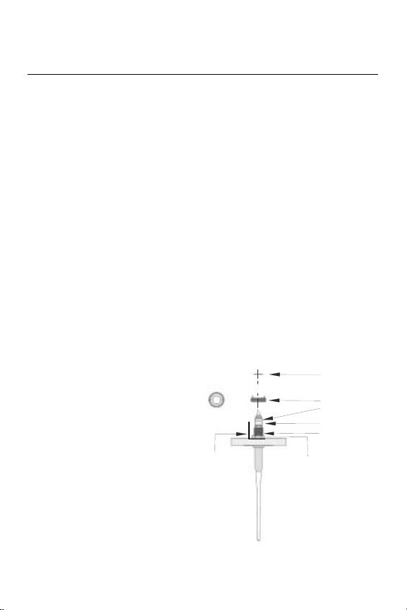
A. Mounting the Rod Antenna, Flanged Version
A1. Mount the flange on top of the rod antenna. Make sure the bottom
side of the flange is flat and all parts are clean and dry.
A2. Secure the flange with the locking nut. Make sure the nut fits
tightly to the flange.
A3. Mount the adapter on
top of the sleeve.
Top View of
Adapter
Locking Rin
Adapter
O-ring
Wave Guide
Sleeve
Antenna
Label
Figure 1. Mounting the adapter
Locking Nut
rod_mount_apdater
Page 5
Quick Installation Guide
00825-0100-4024, Rev AA
March 2004
Rosemount 5600 Series
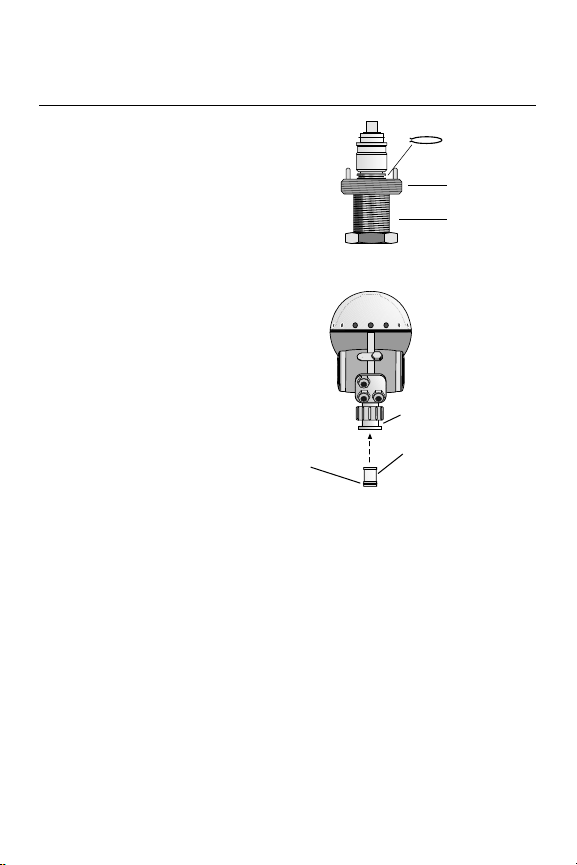
A4. Secure the adapter with
the locking ring.
A5. Carefully fit the flange
and the rod antenna on
the tank nozzle with an
appropriate gasket in
between. Tighten with
screws and nuts.
Figure 2. Securing the adapter
A6. Insert the wave guide
into the upper wave
guide. Make sure the
o-ring at the lower end
of the wave guide tube
is in place.
A7. Place the protection
sleeve on the flange.
Mount the transmitter
head and tighten the
nut. Check that the pins
O-ring
Figure 3. Inserting wave guide tube
Upper Wave Guide
Wave Guide Tube
on the adapter enter
the corresponding grooves on the upper wave guide.
A8. Proceed with Step 2: Connect Wiring and Power Up.
Locking Ring
Adapter
Sleeve
Adapter_LockRing.eps
Waveguide_tube.eps
Page 6
Quick Installation Guide
00825-0100-4024, Rev AA
March 2004
Rosemount 5600 Series
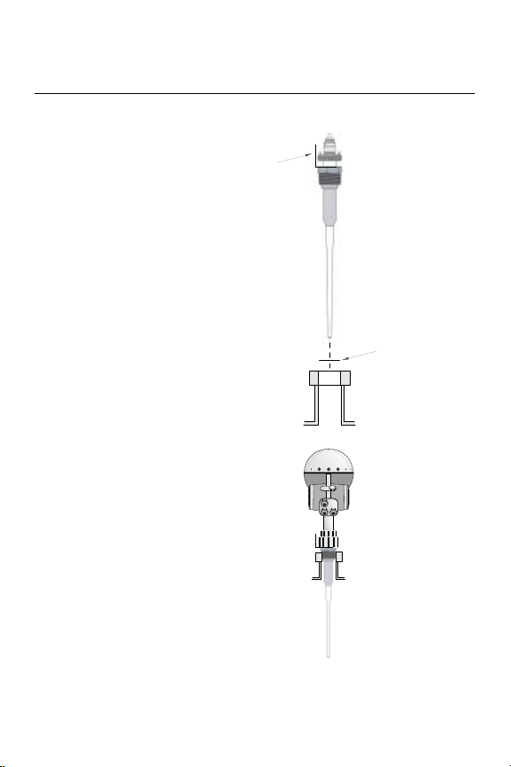
B. Mounting the Rod Antenna, Threaded Version
B1. Carefully fit the rod
antenna into the
threaded nozzle and
screw it in place.
NOTE
For adapters with NPT
threads, pressure-tight
joints may require a sealant.
B2. Insert the wave guide
tube into the upper
wave guide. Make sure
the o-ring at the lower
end of the wave guide
tube is in place. See
Figure 3. Inserting
wave guide tube
B3. Place the protection
sleeve on the flange.
Mount the transmitter
head and tighten the
nut. Check that the
guide pins on the
adapter enter the
corresponding grooves
on the upper wave
guide.
B4. Proceed with Step 2:
Connect Wiring and
Power Up.
Antenna
Label
Gasket for BSP
(G) Threads
Figure 4. Mounting the rod antenna
TH40Head_Nozzle_BSP.eps
Figure 5. Completed mechanical
installation
Rod_Mount_BSP.eps
Page 7
Quick Installation Guide
00825-0100-4024, Rev AA
March 2004
Rosemount 5600 Series
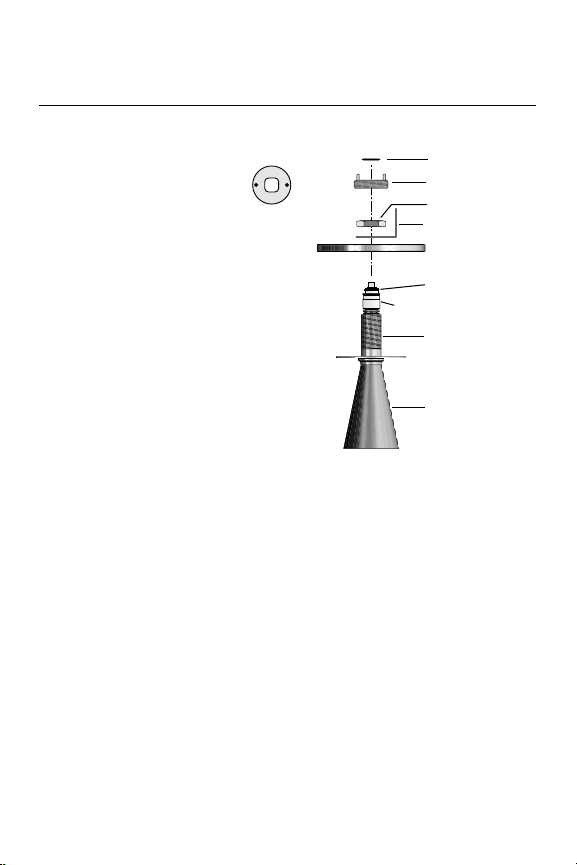
C. Mounting the Cone Antenna
C1. Mount the flange on top
of the cone antenna.
Make sure that the
bottom side of the
flange is flat and all
Top View
of Adapter
parts are clean and dry.
C2. Secure the flange with
the locking nut. Make
sure that the nut fits
tightly to the flange.
C3. Mount the adapter on
top of the sleeve.
C4. Secure the adapter with
the locking ring. See
Figure 2. Securing the
adapter
Figure 6. Mounting the Adapter
C5. Carefully fit the flange
and the cone antenna on the tank nozzle.
C6. Tighten with screws and nuts.
C7. Insert the wave guide tube into the upper wave guide. Make sure
the o-ring at the lower end of the wave guide tube is in place. See
Figure 3. Inserting wave guide tube
Locking Ring
Adapter
Locking Nut
Antenna Label
Flange
O-ring
Tank Seal
Sleeve
Antenna
Flange_Adapter_Mount.eps
Page 8
Quick Installation Guide
00825-0100-4024, Rev AA
March 2004
Rosemount 5600 Series
C8. Place the protection
sleeve on the flange.
Mount the transmitter
head and tighten the
nut. Check that the
guide pins on the
adapter enter the
corresponding grooves
on the upper wave
guide.
C9. Proceed with Step 2:
Connect Wiring and
Power Up.
Figure 7. Mounting the transmitter head
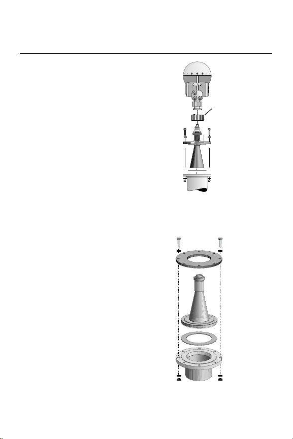
D. Mounting the Process Seal Antenna
D1. Place a gasket on top
of the socket and
mount the antenna.
Use gasket supplied
with the process seal
antenna.
D2. Put the loose flange on
top of the antenna.
D3. Mount the antenna by
tightening the flange to
the tank nozzle.
NOTE
Tighten the flange screws
carefully to the
recommended torque in
Table 1. Tighten opposite
screws in pair.
Figure 8. Mounting the process seal
antenna
Protection Sleeve
Head_Tank_Mount.eps
Process_Seal_Antenna_Mount.eps
Page 9

Quick Installation Guide
00825-0100-4024, Rev AA
March 2004
Table 1. Recommended Torque (Nm) PTFE Seal
DIN Flange PN16 PN40
DN100 11 15
DN150 15 -
ANSI Flange 150 Psi 300 Psi
4 in. 11 15
6 in. 15 10
D4. Insert the wave guide
tube into the upper
wave guide.
D5. Mount the transmitter
head onto the adapter.
D6. Tighten the nut and
make sure that the
transmitter head fits
tightly to the antenna.
D7. Proceed with Step 2:
Connect Wiring and
Power Up.
Rosemount 5600 Series
Nut
Wave Guide Tube
Process_Seal_TH_Mount.eps
Figure 9. Insert wave guide tube and
mount transmitter head
Page 10

Quick Installation Guide
00825-0100-4024, Rev AA
March 2004
Rosemount 5600 Series
E. Mounting the Cone Antenna in a Still-pipe/Bridle
E1. Mount the antenna and the transmitter head in the same way as a
standard cone antenna. See C. Mounting the Cone Antenna.
E2. Make sure that the
inclination of the
transmitter is less than
1°.
Distance from
end of cone to
top of inlet pipe
must be >0 mm
E3. In order to minimize the
influence of disturbing
echoes from inlet and
outlet pipes you may
need to rotate the
transmitter head 90°.
E4. Proceed with Step 2:
Connect Wiring and
Power Up.
max 1°
20,07_Inclination_01.eps
Figure 10. Inclination of transmitter
90˚
Cover Lock
90˚
Figure 11. Rotate transmitter head
F. Mounting the Extended Cone Antenna
F1. Mount the antenna and transmitter head in the same way as a
transmitter with a standard cone antenna. See C. Mounting the
Cone Antenna.
F2. Proceed with Step 2: Connect Wiring and Power Up.
Page 11

Quick Installation Guide
00825-0100-4024, Rev AA
March 2004
Rosemount 5600 Series
G. Mounting the Cone Antenna with Flushing
Connections
G1. The flange is a part of
the antenna assembly
and welded to the cone
antenna. Carefully fit
the antenna assembly
and appropriate gasket
on the tank nozzle.
G2. Insert the wave guide
tube into the upper
wave guide. Make sure
the o-ring at the lower
end of the wave guide
tube is in place. See
Figure 3. Inserting
wave guide tube
.
Figure 12. Mount the flushing cone
antenna on the nozzle
G3. Mount the transmitter
head and tighten the
nut. Check that the
guide pins on the
adapter enter the
corresponding grooves
on the upper wave
guide.
G4. Connect you tubing to
the antenna for
cleaning, purging, or
cooling purposes. Use
a minimum 0.4 in. (10
Figure 13. Mount the transmitter head
mm) tube or pipe.
Typical media to use are nitrogen, air, water, or steam.
G5. Proceed with Step 2: Connect Wiring and Power Up.
Antenna
Assembly
Gasket
Nut
Upper Wave Guide
Protection Sleeve
Guide Pins
Flushing_Antenna_Head.eps
Flushing_Cone_Antenna.eps
Page 12

Quick Installation Guide
00825-0100-4024, Rev AA
March 2004
Rosemount 5600 Series
STEP 2: CONNECT WIRING AND POWER UP
Use information on transmitter label for identification of enabled
options. After identification, use the relevant connection information on
the following pages.
For identification of installed options, see
label on the transmitter head. Find the
5601 xxxxZZxxx where ZZ is the primary
output identification, see table.
5A Non-IS HART/4-20 mA, passive
5B IS HART/4-20 mA, passive
5C Non-IS HART/4-20 mA, active
5D IS HART/4-20 mA, active
7A Foundation Fieldbus, non-IS
7B Foundation Fieldbus, IS
Figure 14. Example of the Rosemount 5600
transmitter head label
Ultra wide 24-240 V DC or AC 0-60 Hz
Figure 15. Power Supply
1
N/L1/+
L/L2/-
Junction Box X1 EEx e
2
3
4
X1
Page 13

Quick Installation Guide
00825-0100-4024, Rev AA
March 2004
Rosemount 5600 Series
Primary
Out Non-IS
Junction Box X1 EEx e
HART®
Interface
1
2
3
4
X1
78
9
456
123
Optional Junction
Box X2 EEx e
Figure 16. Schematic illustration of the
Rosemount 5600 transmitter connection
Junction Box X2 EEx i
X2
7
6
5
4
3
2
1
X2
4
3
2
1
Level
78
456
123
Secondary
Output
1 and 2 Not used
Secondary
6.767
m
Primary
Output IS
9
Output
5600-config_example2, 3, 4_ed3, TH40head_ed3_2
Page 14

Quick Installation Guide
00825-0100-4024, Rev AA
March 2004
Connecting HART devices
Rosemount 5600 Series
Junction Box
EEx e
+
1
-
2
3
4
X1
24-240 V
DC/AC 0-60 Hz
10 W
15 VA
Option 5A Non-IS HART/4-20 mA, passive
+
4-20 mA
External
loop supply
-
Input impedance
~250 Ohm
HART
interface
Figure 17. Typical HART passive output non-IS (primary)
Option 5B IS HART/4-20 mA, passive
1
2
3
4
Junction Box X1
EEx e
24-240 V
DC/AC 0-60 Hz
10 W
15 VA
1
2
3
4
5
6
7
Junction Box X2
EEx i
4-20 mA
+
-
Zener Barrier
Safe areaHazardous Area
External
loop supply
+
-
HART
interface
Figure 18. Typical HART passive output IS (primary)
Service PC
RadarMaster/TankMaster
Input impedance
~250 Ohm
Service PC
RadarMaster/TankMaster
Opt5A.eps
Opt5B.eps
Page 15

Quick Installation Guide
00825-0100-4024, Rev AA
March 2004
Option 5C Non-IS HART/4-20 mA, active
Junction Box
EEx e
Rosemount 5600 Series
Voltage
compliance 7-40 V
+
1
-
2
3
4
X1
24-240 V
DC/AC 0-60 Hz
10 W
15 VA
4-20 mA
Figure 19. Typical HART active output non-IS
Option 5D IS HART/4-20 mA, active
Voltage
compliance 7-40 V
4-20 mA
+
-
Zener Barrier
Safe areaHazardous Area
Junction Box X1
EEx e
24-240 V
DC/AC 0-60 Hz
10 W
15 VA
1
2
3
4
1
2
3
4
5
6
7
Junction Box X2
EEx i
Figure 20. Typical HART active output IS
+
-
Input impedance
~250 Ohm
HART
interface
+
-
HART
interface
Service PC
RadarMaster/TankMaster
Input impedance
~250 Ohm
Service PC
RadarMaster/TankMaster
Opt5C.eps
Opt5D.eps
Page 16

Quick Installation Guide
00825-0100-4024, Rev AA
March 2004
Rosemount 5600 Series
FOUNDATION Fieldbus Non-Intrinsically Safe Wiring
1. Connect fieldbus
wires to terminal 1
and 2 on the X1 side.
These terminals are
marked BUS
terminals. The BUS
terminals are polarity
insensitive.
2. Connect the power
wires to terminal 3
and 4 on the X1 side.
These wires are
separate from the
fieldbus wires.
Junction Box
X1
EEx e
Figure 21. Transmitter Terminal Block
(Non-IS Wiring)
Option 7A FOUNDATION Fieldbus,
non-IS
1
2
3
4
X1
NOTE: Configuration is done
via a FOUNDATION Fieldbus
host.
24-240 V
Safe areaHazardous Area
DC/AC 0-60 Hz
10 W
Opt7A.eps
15 VA
FOUNDATION Fieldbus
I/O
FOUNDATION Fieldbus Intrinsically Safe Wiring
1. Connect fieldbus
wires to terminals 1
and 2 on the X2 side.
These terminals are
marked BUS
terminals. The BUS
terminals are polarity
insensitive.
2. Connect the power
wires to terminal 3
and 4 on the X1 side.
These wires are
separate from the
fieldbus wires.
NOTE
Do not ground out the live signal wiring to the housing when working
on a segment. Grounding the communication wires may result in
temporary loss of communication with all devices on the segment.
Junction Box
X2
EEx i
Option 7B FOUNDATION Fieldbus,
IS
1
2
3
4
5
6
7
X2
NOTE: Configuration is done
via a FOUNDATION Fieldbus
host.
Safe areaHazardous Area
Opt7B.eps
FOUNDATION Fieldbus
Figure 22. Transmitter Terminal Block
(IS Wiring)
I/O
Page 17

Quick Installation Guide
00825-0100-4024, Rev AA
March 2004
Connecting the Rosemount 2210 Display Unit
Connect the Display Unit to the X2 terminal in the Intrinsically Safe
Junction Box by the following four wires:
• Grounding wire to the ground terminal
• Signal wires to terminal 6 and 7
• Supply voltage to terminal 5
Rosemount 5600 Series
12345678
12345678
X11
1
2
3
4
X12
1234
with
temperature
output
IS Ground
DP DB
DP DA
DP
X2
+
Transmitter Head
Intrinsically Safe
Junction Box X2 EEx i
7
6
5
4
3
2
1
X12:4
X12:3
X12:2
X12:1
1234
1234
X11
X12
without
temperature
output
Figure 23. Connection of junction box with and without temperature
outputs
1. For power supply connect a wire between terminal block X2,
position 5 and terminal block X12, position 1.
2. For communication connect a wire between terminal block X2,
position 6 and terminal block X12, position 2, and a wire between
terminal block X2 position 7 and terminal block X12 position 3.
Finally for grounding connect a wire from the IS Ground screw in the
X2 terminal compartment to terminal block X12 position 4.
NOTE
For detailed information on connecting temperature sensors, see
Reference Manual 00809-0100-4024.
5600-rdu40_x12_th_x2.eps
Page 18

Quick Installation Guide
00825-0100-4024, Rev AA
March 2004
Rosemount 5600 Series
STEP 3: CONFIGURE THE TRANSMITTER
Configure your Rosemount 5600 transmitter using one of the following
available configuration tools.
PC Configuration Software Radar Master
The program on the CD will automatically start and suggest an
installation of the Radar Master software. You will need to restart your
PC prior to running the Radar Master program.
Configure the Transmitter using the Wizard
The guided setup contains seven steps and guides you through the
basic setup procedure.
Hand-held Communicator
For more information on the 375 Field Communicator see document
00809-0100-4276 and for the 275 HART Communicator see document
00275-8026-0002.
2210 Display Unit
Use the four softkeys to navigate through the different menus and to
select various functions for service and configuration. To install the
Rosemount 5600 select setup from the Main Menu and choose your
setup option. For further information see document number
00809-0100-4024.
AMS
The program on the CD will automatically start and suggest an
installation using AMS. You will need to restart your PC prior to running
the AMS program.
Page 19

Quick Installation Guide
00825-0100-4024, Rev AA
March 2004
Rosemount 5600 Series
PRODUCT CERTIFICATIONS
Approved Manufacturing Locations
Saab Marine Electronics AB – Gothenburg, Sweden
European Union Directive Information
The EC declaration of conformity for all applicable European directives
for this product can be found on the Rosemount website at
www.rosemount.com. A hard copy may be obtained by contacting our
local sales representative.
ATEX Directive (94/9/EC)
Rosemount Inc. complies with the ATEX Directive.
Ordinary Location Certification for Factory Mutual
As standard, the transmitter has been examined and tested to
determine that the design meets basic electrical, mechanical, and fire
protection requirements by FM, a nationally recognized testing
laboratory (NRTL) as accredited by the Federal Occupational Safety
and Health Administration (OSHA).
Page 20

Quick Installation Guide
00825-0100-4024, Rev AA
March 2004
Rosemount 5600 Series
Hazardous Locations Certifications
ATEX Approvals
5600 Series Level Transmitter
E1 Certificate Number: Sira 03ATEX 1294X
ATEX Category Marking II 1/2 G
With Intrinsically Safe Outputs (only)
ATEX Marking: EX II (2) (1) 1/2 G
Safety Coding: EEx de [ib] [ia] IIC T6 (T
With Non-IS Primary Output and IS Display Output
ATEX Marking: EX II (1) 1/2 G
Safety Coding: EEx de [ia] IIC T6 (T
With Non-IS Primary and/or Non-IS Secondary Outputs
ATEX Marking: EX II 1/2 G
Safety Coding: EEx de IIC T6 (T
amb
Max supply voltage: 55 Vdc
Passive analog output 4-20mA,
Label identification = HART passive.
Voltage compliance 7-30V:
< 30 V
U
i
< 200 mA
I
i
Pi < 1.3 W
C
= 0 µF
i
= 0 mH
L
i
-40°C, +70°C)
amb
-40°C, +70°C)
amb
-40°C, +70°C)
Active analog output 4-20mA,
Label identification = HART active.
Max load 300Ω:
U
< 23.1 V
o
< 125.7 mA
I
o
P
< 0.726 W
o
<0.14 µF
C
ext
< 2.2 mH
L
ext
Page 21

Quick Installation Guide
00825-0100-4024, Rev AA
March 2004
Rosemount 5600 Series
FOUNDATION Fieldbus,
Label identification = F
< 30 V
U
i
I
< 300 mA
i
OUNDATION fieldbus.
Pi < 1.3 W
= 0 µF
C
i
L
= 0 mH
i
SPECIAL CONDITIONS FOR SAFE USE (X)
As alloys may be used as the enclosure (or other parts) material and
be at the accessible surface of this equipment, in the event of rare
incidents, ignition sources due to impact and friction sparks could
occur. This shall be considered when the equipment is being installed
in locations that specifically require group II, category 1G equipment.
Under certain extreme circumstances, the non-metallic parts of the
equipment may be capable of generating an ignition-capable level of
electrostatic charge. Therefore, when used for applications that
specifically require group II, category 1 equipment, the equipment
shall not be installed in a location where the external conditions are
conductive to the build-up of electrostatic charge on such surfaces.
Additionally, the equipment non-metallic parts shall only be cleaned
with a damp cloth.
INSTRUCTIONS SPECIFIC TO HAZARDOUS AREA
INSTALLATION
The equipment may be used with flammable gases and vapors with
apparatus Group IIC.
The Transmitter Head is certified for use in ambient temperatures in
the range -40°C to 70°C and should not be used outside this range.
The equipment is designed to be mounted across the boundary
between a cat 1 and cat 2 area. There are various cat 1 area within the
range from -40°C to 400°C, -1 to 55 bar that can be considered. It is
the responsibility of the user to select the appropriate antenna
Page 22

Quick Installation Guide
00825-0100-4024, Rev AA
March 2004
including tank seal to match the tank process conditions.
The product must be installed by suitably trained personnel and
carried out in accordance with all appropriate international, national,
and local standard codes of practice and site regulations for
intrinsically safe apparatus and in accordance with the instructions
contained with in this manual.
Repair of this equipment shall be carried out by the manufacturer or in
accordance with the applicable code of practice.
All externally connected intrinsically safe apparatus must comply with
the specified IS entity parameters.
The Flameproof/Exploisionproof enclosure may not be opened while
energized.
The certificate has special conditions for safe use associated with it,
noted by the X on the end of the certificate no., which must be
observed when the equipment is installed.
If the equipment is likely to come into contract with aggressive
substances, then it is the responsibility of the user to take suitable
precautions that prevent it from being adversely affected, thus
ensuring that the type of protection is not compromised.
Rosemount 5600 Series
Aggressive substances - e.g. solvents that may affect polymeric
materials
Suitable precautions - e.g. regular checks as part of routine
inspections or establishing from the material’s data sheet that it is
resistant to specific chemicals.
Page 23

Quick Installation Guide
00825-0100-4024, Rev AA
March 2004
2210 Display Unit
E1 Certificate Number: Sira 00ATEX 2062
ATEX Category Marking II 1/2 G
Without Temperature Inputs
ATEX Marking: EX II 1/2 G
Safety Coding: EEx ib IIC T4 (T
With Temperature Inputs
ATEX Marking: EX II 1/2 G
Safety Coding: EEx ib [ia] IIC T4, (T
Factory Mutual (FM)
5600 Series Level Transmitter
E5 Certificate Number: 4D5A9.AX
With Intrinsically safe outputs
(all versions except those listed below)
Explosion proof with IS outputs for HAZLOC
Class I, Division 1, Group A, B, C and D
Max operating temperature +70°C
Use conductors rated at least 85°C
Shall be installed in accordance with System control drawing
9150074-994.
With Non-IS Secondary Outputs (codes 1 and 3)
Explosion proof
Class I, Division 1, Group A, B, C and D
Max operating temperature +70°C
Use conductors rated at least 85°C
Rosemount 5600 Series
-40°C, +70°C)
amb
-40°C, +70°C)
amb
Page 24

Quick Installation Guide
00825-0100-4024, Rev AA
March 2004
2210 Display Unit
E5 Certificate: 4D5A9.AX
All Versions
Intrinsic Safe for HAZLOC
Class I, Division 1, Group A, B, C and D T4
Max operating temperature +70°C
Shall be installed in accordance with System control drawing
9150074-997.
Canadian Standards Association (CSA)
5600 Series Level Transmitter
E6 Certificate Number: 2003.153280-1346169
With Non-IS Primary and/or Secondary Outputs
Explosion proof Ex de IIC T6
Shall be installed in accordance with System control drawing
9150074-937.
Factory seal, conduit seal not required.
With IS Display Outputs, IS Primary and/or Secondary
Outputs
Explosion proof Ex de [ib/ia] IIC T6
Shall be installed in accordance with System control drawing
9150074-939.
Factory seal, conduit seal not required.
2210 Display Unit
E6 Certificate Number: 2003.153280-1346165
Without Temperature Inputs
Intrinsically safe EEx ib IIC T4, (T
With Temperature Inputs
Intrinsically safe EEx ib [ia] IIC T4, (T
Shall be installed in accordance with System control drawing
9150074-944.
Rosemount 5600 Series
-40°C, +70°C)
amb
-40°C, +70°C)
amb
Page 25

Quick Installation Guide
00825-0100-4024, Rev AA
March 2004
Table 2. Symbols used on 5600 Series Level Transmitter and
2210 Display Unit
Rosemount 5600 Series
The CE marking symbolizes
the conformity of the product
with the applicable Community
requirements.
The Ex Certificate is a
statement of an independent
Certification Body declaring
that this product meets the
requirement of the applicable
European Intrinsic Safety
directives.
The FM symbol indicates that
the marked equipment is
certified by FM - Factory
Mutual Research Corporation
according to FMRC standards
and are applicable for
installation in hazardous
locations.
The device uses
non-harmonized radio
frequencies.
Protective Earth
Ground
Power Supply
External cabling must be
approved for use in min. 75°C.
Page 26

Quick Installation Guide
00825-0100-4024, Rev AA
March 2004
Rosemount 5600 Series
 Loading...