

Page 1

Quick Start Guide
00825-0800-4408, Rev AA
February 2020
Rosemount™ 5408 Level Transmitter
with Modbus® Protocol
Page 2

Quick Start Guide February 2020
Contents
About this guide...........................................................................................................................3
Confirm approval type..................................................................................................................5
Components of the parabolic antenna......................................................................................... 6
Mount the transmitter..................................................................................................................7
Adjust the inclination of the antenna..........................................................................................11
Plug and seal the air purge entry.................................................................................................14
Adjust display orientation (optional).......................................................................................... 15
Prepare the electrical connections..............................................................................................16
Connect wiring and power up.....................................................................................................19
Performance specifications........................................................................................................ 23
Functional specifications............................................................................................................ 25
Physical specifications................................................................................................................ 27
2 Rosemount 5408 Level Transmitter
Page 3

February 2020 Quick Start Guide
1 About this guide
This Quick Start Guide provides basic guidelines for the Rosemount 5408
Level Transmitter with Modbus® Protocol.
WARNING
Failure to follow safe installation and servicing guidelines could result in
death or serious injury.
• Ensure the transmitter is installed by qualified personnel and in
accordance with applicable code of practice.
• Use the equipment only as specified in this Quick Start Guide. Failure to
do so may impair the protection provided by the equipment.
• For installations in hazardous locations, the transmitter must be installed
according to the Rosemount 5408 Product Certifications document and
System Control Drawing (D7000005-811).
• Repair, e.g. substitution of components, etc. may jeopardize safety and
is under no circumstances allowed.
Explosions could result in death or serious injury.
• Verify that the operating atmosphere of the transmitter is consistent
with the appropriate hazardous locations certifications.
• Before connecting a handheld communicator in an explosive
atmosphere, ensure the instruments are installed in accordance with
intrinsically safe or non-incendive field wiring practices.
• In Explosion-proof/Flameproof installations, do not remove the
transmitter covers when power is applied to the unit.
• Both transmitter covers must be fully engaged to meet Explosion-proof/
Flameproof requirements.
Electrical shock could cause death or serious injury.
• In Explosion-proof/Flameproof installations, avoid contact with the leads
and terminals. High voltage that may be present on leads can cause
electrical shock.
• Ensure the mains power to the transmitter is off and the lines to any
other external power source are disconnected or not powered while
wiring the transmitter.
Quick Start Guide 3
Page 4

Quick Start Guide February 2020
WARNING
Process leaks could result in death or serious injury.
• Ensure that the transmitter is handled carefully. If the process seal is
damaged, gas might escape from the tank.
WARNING
Physical access
Unauthorized personnel may potentially cause significant damage to and/or
misconfiguration of end users’ equipment. This could be intentional or
unintentional and needs to be protected against.
Physical security is an important part of any security program and
fundamental to protecting your system. Restrict physical access by
unauthorized personnel to protect end users’ assets. This is true for all
systems used within the facility.
CAUTION
Hot surfaces
The flange and process seal may be hot at high process temperatures. Allow
to cool before servicing.
4 Rosemount 5408 Level Transmitter
Page 5

February 2020 Quick Start Guide
2 Confirm approval type
For hazardous locations transmitters labeled with multiple approval types:
Procedure
Permanently mark the checkbox of the selected approval type(s).
Figure 2-1: Label with Multiple Approval Types
Quick Start Guide 5
Page 6

2x
[
(
[
*
[
'
[
&
[
%
[
$
[
)
Quick Start Guide February 2020
3 Components of the parabolic antenna
3.1 Components of the threaded version
Figure 3-1: Components
A. Antenna
B. Purge plug kit (blind plug and bonded seal)
C. Threaded sleeve
D. M20 adapter
E. Lock nut BSPP (G) 3½-in.
F. Antenna adapter with ball joint
G. O-ring
6 Rosemount 5408 Level Transmitter
Page 7

B
A
February 2020 Quick Start Guide
4 Mount the transmitter
4.1 Mount the threaded version
Procedure
1. Remove the lock nut.
2. Mount the O-ring.
3. Mount the antenna adapter on the mounting flange plate. Ensure the
antenna adapter fits tightly to the mounting flange plate.
A. Ø 3.98 ± 0.02 in. (Ø 101 ± 0.6 mm) or G 3½-in.
B. Max. 0.59 in. (15 mm)
Quick Start Guide 7
Page 8

27 mm
Torque 180 in-lb (20 N-m)
Quick Start Guide February 2020
4. Remove the M20 adapter and visually inspect the O-rings for damage
and dirt.
5. Carefully insert the antenna.
6. Secure the antenna.
8 Rosemount 5408 Level Transmitter
Page 9

H2 mm
Torque 5 in-lb (0.5 N-m)
February 2020 Quick Start Guide
7. Tighten the set screw.
8. Position the antenna assembly onto the mounting frame.
Example
Deck/platform mounted
9. Tighten the bolts and nuts.
It is recommended that insulating bushes are fitted to the mounting
bolts.
Quick Start Guide 9
Page 10

Quick Start Guide February 2020
Postrequisites
1. Adjust the inclination of the antenna (see Adjust the inclination of
the antenna).
2. Plug and seal the air purge entry (see Plug and seal the air purge
entry).
10 Rosemount 5408 Level Transmitter
Page 11

H6 mm
February 2020 Quick Start Guide
5 Adjust the inclination of the antenna
Prerequisites
WARNING
Contents may be under pressure.
• Do not loosen the M8 screws while in operation. Attempting to do so
may release pressurized gases, resulting in serious injury or death.
Procedure
1. Loosen the M8 screws until the antenna can rotate smoothly.
2. Rotate the antenna so the air purge connection is directed toward
the host platform/structure.
Quick Start Guide 11
Page 12

H6 mm
Torque 65 in-lb (7 N-m)
Quick Start Guide February 2020
3. Place the supplied circular level on top of the antenna assembly.
4. Adjust the inclination of the antenna.
5. Gradually tighten the M8 screws.
12 Rosemount 5408 Level Transmitter
Page 13

Torque 355 in-lb (40 N-m)
60 mm
36 mm
February 2020 Quick Start Guide
6. Remove the circular level.
7. Mount the transmitter head.
Align the marking on the sensor module with the air purge
connection.
Quick Start Guide 13
Page 14

17 mm
Torque 180 in-lb (20 N-m)
Quick Start Guide February 2020
6 Plug and seal the air purge entry
Procedure
Plug and seal the entry with the supplied blind plug and bonded seal.
14 Rosemount 5408 Level Transmitter
Page 15

Torque 30 in-lb (3 N-m)
H3/32 in.
February 2020 Quick Start Guide
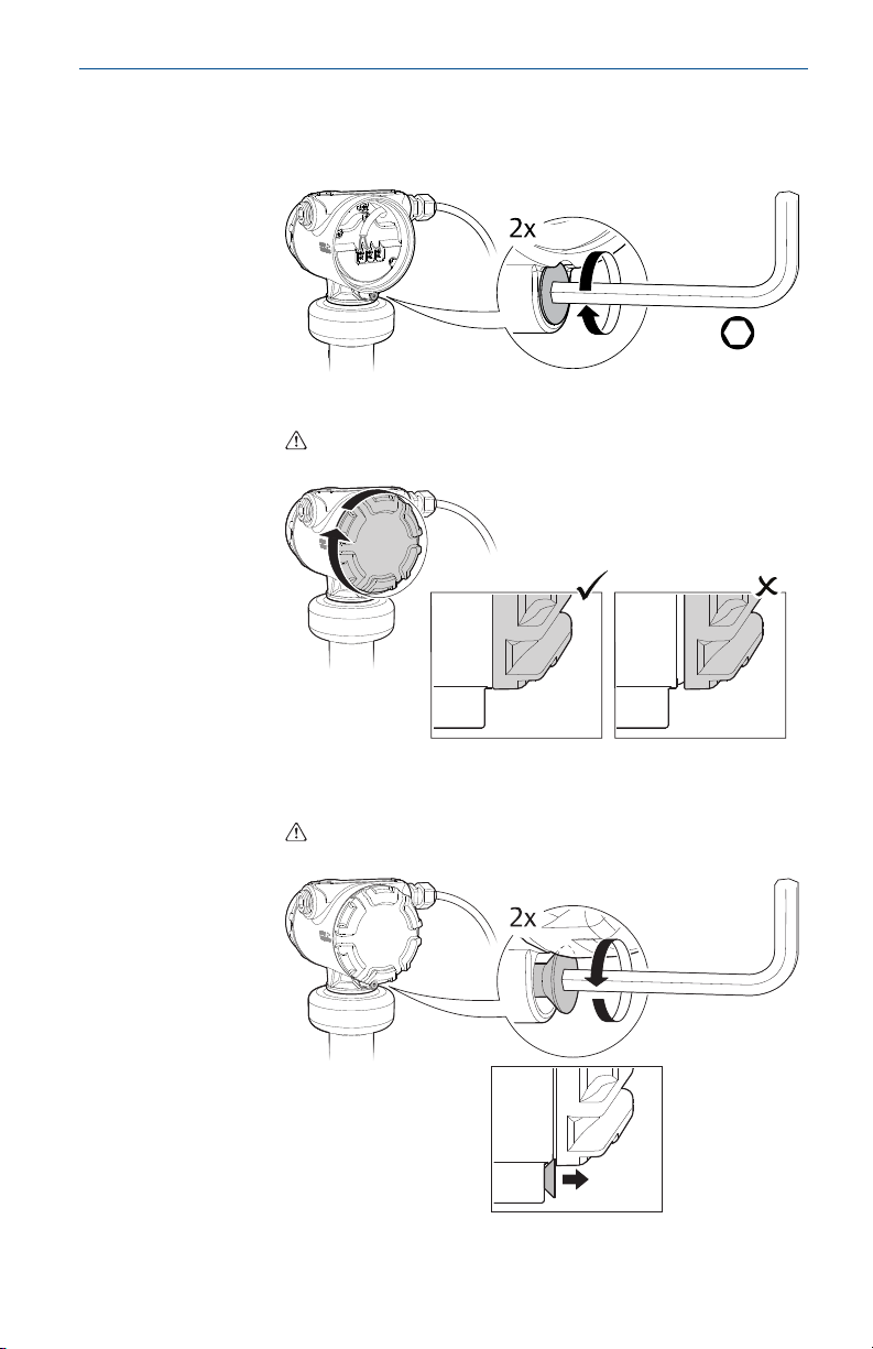
7 Adjust display orientation (optional)
To improve field access to wiring or to better view the optional LCD display:
Prerequisites
Note
In high vibration applications, the transmitter housing must be fully
engaged into the sensor module to meet the vibration test specifications.
This is achieved by rotating the transmitter housing clockwise to thread
limit.
Procedure
1. Loosen the set screw until the transmitter housing can rotate
smoothly.
2. First, rotate the housing clockwise to the desired location. If the
desired location cannot be achieved due to thread limit, rotate the
housing counterclockwise to the desired location (up to 360° from
thread limit).
3. Re-tighten the set screw.
Figure 7-1: Rotate the Transmitter Housing
Quick Start Guide 15
Page 16

$
%
Quick Start Guide February 2020
8 Prepare the electrical connections
8.1 Cable selection
RS-485 bus
Power
supply
Use wire rated at least 5 °C above maximum ambient temperature.
Use shielded twisted pair wiring with a characteristic
impedance of 120 Ω (typically 24 AWG).
Use 24-14 AWG wire. Twisted pairs and shielded wiring are
recommended for environments with high EMI
(electromagnetic interference).
8.2 Cable gland/conduit
For explosion-proof/flameproof installations, only use cable glands or
conduit entry devices certified explosion-proof or flameproof.
8.3 Grounding
Make sure grounding is done according to national and local electrical
codes. Failure to do so may impair the protection provided by the
equipment.
Transmitter housing
The most effective grounding method is direct connection to earth ground
with minimal impedance. There are two grounding screw connections
provided (see Figure 8-1).
Figure 8-1: Ground Screws
A. Internal ground screw
B. External ground screw
Cable shield grounding
Make sure the instrument cable shield is:
• Trimmed close and insulated from touching the transmitter housing.
• Connected to a good earth ground at the power supply end.
16 Rosemount 5408 Level Transmitter
Page 17

C
C
B
February 2020 Quick Start Guide
Figure 8-2: Cable Shield
A. Insulate shield and drain wire
B. Minimize distance
C. Connect drain wire to a good earth ground
Note
Do not ground the shield and its drain wire at the transmitter. If the cable
shield touches the transmitter housing, it can create ground loops and
interfere with communications.
Common signal reference ground for RS-485
Best practice is to connect a third reference wire to the "COM" terminal
(common signal reference ground).
If a common reference wire is not used, then the "COM" terminal should be
connected to the “–“ power terminal. The common mode difference
between the host RS-485 and the negative power supply must be between
-7 V and +12 V.
8.4
Quick Start Guide 17
Power supply
The transmitter operates on 9-36 Vdc at the transmitter terminals.
Page 18

H
I
J
G
F
A
B
D
120Ω
-
+
E C
D
MA
MB
COM
-
+
Quick Start Guide February 2020
8.5 Wiring diagram
Figure 8-3: Modbus® RS-485 Communication
A. "A" line
B. "B" line
C. Modbus RS-485 host
D. Common signal reference ground
E. Power supply
F. Modbus RS-485 B connection (RX/TX+)
G. Modbus RS-485 A connection (RX/TX-)
H. Positive power input terminal
(1) The designation of the connectors do not follow the EIA-485 standard, which states
I. Negative power input terminal
J. Built-in 120 Ω termination resistor (connect jumper if last device on the
bus)
(1)
(1)
that RX/TX- should be referred to as 'A' and RX/TX+ as 'B'.
18 Rosemount 5408 Level Transmitter
Page 19

February 2020 Quick Start Guide
9 Connect wiring and power up
Procedure
1. Verify the power supply is disconnected.
2. Remove the cover.
3. Remove the plastic plugs.
4. Pull the cable through the cable gland/conduit.
(2)
Identification of thread size and type:
(2) Unless marked, the conduit/cable entries in the transmitter housing use a ½–14 NPT
thread form.
Quick Start Guide 19
Page 20

Torque 7 in-lb (0.8 N-m)
Quick Start Guide February 2020
5. Connect the cable wires (see Wiring diagram).
6. Ensure proper grounding (see Grounding).
7. Tighten the cable gland.
Apply PTFE tape or other sealant to the threads.
Note
Make sure to arrange the wiring with a drip loop.
8. Seal any unused ports with the enclosed metal plug.
Apply PTFE tape or other sealant to the threads.
20 Rosemount 5408 Level Transmitter
Page 21
H2.5 mm
February 2020 Quick Start Guide
9. Attach and tighten the cover.
a) Verify the cover jam screw is completely threaded into the
housing.
b) Attach and tighten the cover.
Make sure the cover is fully engaged. There should be no
gap between the cover and the housing.
c) Turn the jam screw counterclockwise until it contacts the
cover.
Required for explosion-proof/flameproof installations
only.
Quick Start Guide 21
Page 22

Quick Start Guide February 2020
d) Turn the jam screw an additional ½ turn counterclockwise to
secure the cover.
10. Connect the power supply.
22 Rosemount 5408 Level Transmitter
Page 23

February 2020 Quick Start Guide
10 Performance specifications
10.1 General
10.1.1 Reference conditions
• Measurement target: Stationary metal plate, no disturbing objects
• Temperature: 59 to 77 °F (15 to 25 °C)
• Ambient pressure: 14 to 15 psi (960 to1060 mbar)
• Relative humidity: 25-75%
• Damping: Default value, 0 s
10.1.2 Instrument accuracy (under reference conditions)
Range < 130 ft. (40 m)
Range > 130 ft. (40 m)
10.1.3 Measuring range
10 to 262 ft. (3 to 80 m)
10.1.4 Repeatability
±0.04 in. (±1 mm)
±0.12 in. (±3 mm)
±0.25 in. (±6 mm)
(3)
(3)
10.1.5 Ambient temperature effect
±0.04 in. (±1 mm)/10 K
(4)
10.1.6 Sensor update rate
Measuring rate
10 Hz
Burst rate
5 Hz (or configurable 2 to 10 Hz)
10.1.7 Beam width
4.5°
(3)
Refers to inaccuracy according to IEC 60770-1 when excluding installation
dependent offset. See the IEC 60770-1 standard for a definition of radar specific
performance parameters and if applicable corresponding test procedures.
(4)
Ambient temperature effect specification valid over temperature range -40 °F to 176
°F (-40 °C to 80 °C).
Quick Start Guide 23
Page 24

Quick Start Guide February 2020
10.2 Environment
10.2.1 Vibration resistance
• 2 g at 10-180 Hz according to IEC 61298-3, level “field with general
application”
• IACS UR E10 test 7
For compliance with these standards, the transmitter housing must be fully
engaged into the sensor module. This is achieved by rotating the transmitter
housing clockwise to thread limit.
10.2.2 Electromagnetic compatibility (EMC)
• EMC Directive (2014/30/EU): EN 61326-1
• EN 61326-2-3
• NAMUR recommendations NE21
Tests are performed with the recommended electrical wiring using a third
wire interconnecting the COM terminals of the RS-485 network, termination
at each end, and good protective earth.
10.2.3 Built-in lightning protection
EN 61326, IEC 61000-4-5, level 6kV
(5)
10.2.4 Radio approvals
• Radio Equipment Directive (2014/53/EU): ETSI EN 302 372, ETSI EN 302
729 and EN 62479
• Part 15 of the FCC Rules
• Industry Canada RSS 211
(5) In challenging applications where the dynamic of the transmitter sensitivity is
utilized by multiple factors such as small aperture antenna, very low product
dielectric constant and/or turbulent surface, the margin for additional influence due
to extreme EMC may be limited.
24 Rosemount 5408 Level Transmitter
Page 25

February 2020 Quick Start Guide
11 Functional specifications
11.1 General
11.1.1 Field of application
Measurement of waves, sea level and air gap in offshore, maritime and
coastal environments.
11.1.2 Measurement principle
Frequency Modulated Continuous Wave (FMCW)
11.1.3 Frequency range
24.05 to 26.5 GHz
11.1.4 Maximum output power
-5 dBm (0.32 mW)
11.1.5 Power consumption
Max. 1 W, average < 0.4 W
11.1.6 Humidity
0 - 100% relative humidity, non-condensing
11.1.7 Turn-on time
(6)
< 10 s
11.2
Quick Start Guide 25
Temperature limits
Verify that the operating atmosphere of the transmitter housing is
consistent with the appropriate hazardous locations certifications, see the
Product Certifications document.
Table 11-1: Ambient Temperature Limits
Description Operating limit Storage limit
Without LCD
display
With LCD
(1)
display
(1) LCD display may not be readable and LCD display updates will be slower at
temperatures below -4 °F (-20 °C).
(6)
Time from when power is applied to the transmitter until performance is within
specifications.
-40 °F to 176 °F (-40 °C to 80 °C)
-58 °F to 176 °F (-50 °C to 80 °C)
-40 °F to 176 °F (-40 °C to 80 °C)
Page 26

104 (40)
176 (80)
482
(250)
-76
(-60)
248
(120)
-40 (-40)
A
B
Quick Start Guide February 2020
The ambient temperature limits may be further restricted by the process
temperature as described by Figure 11-1.
Figure 11-1: Ambient Temperature vs. Process Temperature
A. Ambient temperature °F (°C)
B. Process temperature °F (°C)
Aside from ambient temperature variations, heat from the process may be
transferred to the transmitter housing. Being exposed to a high process
temperature without extra cooling for an extended period of time may
cause the electronics temperature to exceed the allowed limit and thereby
affect the transmitter's performance and reliability. The latter are potential
risks whenever a transmitter has shut down due to high electronics
temperature. The transmitter will warn about the electronics temperature
being out of limits.
26 Rosemount 5408 Level Transmitter
Page 27

February 2020 Quick Start Guide
12 Physical specifications
12.1 Housing and enclosure
12.1.1 Electrical connections
Two cable/conduit entries (½-14 NPT or M20 x 1.5)
Optional adapters: M12 4-pin male eurofast connector or A size Mini 4-pin
male minifast connector
12.1.2 Materials
• Electronics housing: Stainless Steel Grade CF-8M (ASTM A743)
• Sensor module: 316L SST
12.1.3 Weight
• Stainless steel housing: 10.0 lb (4.5 kg)
• Parabolic antenna assembly: 8.8 lb (4.0 kg)
12.1.4 Ingress protection
IP 66/67/68
(9)
and NEMA® 4X
12.2 Material exposed to tank atmosphere
(7)
(8)
Parabolic antenna
• 316/316L SST (EN 1.4404)
• PTFE fluoropolymer
• FVMQ fluorosilicone (O-ring)
(7) Fully functional transmitter with sensor module, housing, terminal block, LCD
display, and covers.
(8) Weight does not include mounting flange plate.
(9)
The transmitter meets IP 68 at 9.8 ft. (3 m) for 30 minutes.
Quick Start Guide 27
Page 28

*00825-0800-4408*
00825-0800-4408, Rev. AA
Quick Start Guide
February 2020
Global Headquarters
Emerson Automation Solutions
6021 Innovation Blvd.
Shakopee, MN 55379, USA
+1 800 999 9307 or +1 952 906 8888
+1 952 949 7001
RFQ.RMD-RCC@Emerson.com
Manufactured by
Rosemount Tank Radar AB
Layoutvägen 1
S-435 33 Mölnlycke
Sweden
+46 31 337 00 00
+46 31 25 30 22
Linkedin.com/company/Emerson-
Automation-Solutions
Twitter.com/Rosemount_News
Facebook.com/Rosemount
Youtube.com/user/
RosemountMeasurement
North America Regional Office
Emerson Automation Solutions
8200 Market Blvd.
Chanhassen, MN 55317, USA
+1 800 999 9307 or +1 952 906 8888
+1 952 949 7001
RMT-NA.RCCRFQ@Emerson.com
©
2020 Emerson. All rights reserved.
Emerson Terms and Conditions of Sale are
available upon request. The Emerson logo is a
trademark and service mark of Emerson Electric
Co. Rosemount is a mark of one of the Emerson
family of companies. All other marks are the
property of their respective owners.
 Loading...