

Page 1
Reference Manual
00809-0100-4032, Rev AA
November 2005
Rosemount 5400 Series
Two-wire Radar Level Transmitter with FOUNDATION™ Fieldbus
www.rosemount.com
Page 2

Page 3

Reference Manual
00809-0100-4032, Rev AA
November 2005
Rosemount 5400 Series
Rosemount 5400 Series
NOTICE
Read this manual before working with the product. For personal and system safety, and for
optimum product performance, make sure you thoroughly understand the contents before
installing, using, or maintaining this product.
Within the United States, Rosemount Inc. has two toll-free assistance numbers.
Customer Central: 1-800-999-9307(7:00 a.m. to 7:00 p.m. CST)
Technical support, quoting, and order-related questions.
North American Response Center:
Equipment service needs.
1-800-654-7768 (24 hours a day – Includes Canada)
For equipment service or support needs outside the United States, contact your local
Rosemount representative.
NOTICE
There are no health hazards from the Rosemount 5400 Series transmitter. The microwave
power density in the tank is only a small fraction of the allowed power density according to
international standards.
The products described in this document are NOT designed for nuclear-qualified
applications.
Using non-nuclear qualified products in applications that require nuclear-qualified hardware
or products may cause inaccurate readings.
For information on Rosemount nuclear-qualified products, contact your local Rosemount
Sales Representative.
This product is designed to meet FCC and R&TTE requirements.
This device complies with part 15 of the FCC rules. Operation is subject to the following two
conditions: (1) This device may not cause harmful interference, and (2) this device must
accept any interference received, including interference that may cause undesired
operation.
Rosemount 5400 Series Radar Transmitter may be protected by one or more U.S. Patents pending and foreign
patents pending.
Rosemount and the Rosemount logotype are registered trademarks of Rosemount Inc.
HART is a registered trademark of the HART Communication Foundation.
Teflon, VITON, and Kalrez are registered trademarks of DuPont Performance Elastomers.
AMS Suite is a trademark of Emerson Process Management.
F
OUNDATION is a trademark of the Fieldbus Foundation.
Cover Photo: 5400_08
www.rosemount.com
Page 4

Page 5

Reference Manual
00809-0100-4032, Rev AA
November 2005
Rosemount 5400 Series
Table of Contents
SECTION 1
Introduction
SECTION 2
Transmitter Overview
SECTION 3
Installation
Safety Messages . . . . . . . . . . . . . . . . . . . . . . . . . . . . . . . . . . . . . . . . . 1-1
Manual Overview . . . . . . . . . . . . . . . . . . . . . . . . . . . . . . . . . . . . . . . . . 1-2
Service Support . . . . . . . . . . . . . . . . . . . . . . . . . . . . . . . . . . . . . . . . . . 1-3
Theory of Operation. . . . . . . . . . . . . . . . . . . . . . . . . . . . . . . . . . . . . . . 2-1
Components of the transmitter . . . . . . . . . . . . . . . . . . . . . . . . . . . . . . 2-2
System Architecture. . . . . . . . . . . . . . . . . . . . . . . . . . . . . . . . . . . . . . . 2-3
Process Characteristics . . . . . . . . . . . . . . . . . . . . . . . . . . . . . . . . . . . . 2-4
Dielectric constant . . . . . . . . . . . . . . . . . . . . . . . . . . . . . . . . . . . . . 2-4
Foam . . . . . . . . . . . . . . . . . . . . . . . . . . . . . . . . . . . . . . . . . . . . . . . 2-4
Turbulence . . . . . . . . . . . . . . . . . . . . . . . . . . . . . . . . . . . . . . . . . . . 2-4
Temperature/Pressure/
Density and Vapor . . . . . . . . . . . . . . . . . . . . . . . . . . . . . . . . . . . . . 2-4
Condensation . . . . . . . . . . . . . . . . . . . . . . . . . . . . . . . . . . . . . . . . . 2-4
Tank Characteristics. . . . . . . . . . . . . . . . . . . . . . . . . . . . . . . . . . . . 2-4
Antenna Selection Guide/Measuring Range . . . . . . . . . . . . . . . . . . . . 2-5
Safety Messages . . . . . . . . . . . . . . . . . . . . . . . . . . . . . . . . . . . . . . . . . 3-1
Installation Procedure . . . . . . . . . . . . . . . . . . . . . . . . . . . . . . . . . . . . . 3-2
Mounting Considerations . . . . . . . . . . . . . . . . . . . . . . . . . . . . . . . . . . . 3-3
Socket Recommendation . . . . . . . . . . . . . . . . . . . . . . . . . . . . . . . . 3-3
Free Space . . . . . . . . . . . . . . . . . . . . . . . . . . . . . . . . . . . . . . . . . . . 3-4
Recommended Mounting Position . . . . . . . . . . . . . . . . . . . . . . . . . 3-5
Beam Width . . . . . . . . . . . . . . . . . . . . . . . . . . . . . . . . . . . . . . . . . . 3-6
Vessel Characteristics . . . . . . . . . . . . . . . . . . . . . . . . . . . . . . . . . . 3-8
Disturbing objects . . . . . . . . . . . . . . . . . . . . . . . . . . . . . . . . . . . . . . 3-8
Mechanical Installation . . . . . . . . . . . . . . . . . . . . . . . . . . . . . . . . . . . . 3-9
Mounting in Pipes. . . . . . . . . . . . . . . . . . . . . . . . . . . . . . . . . . . . . 3-11
Recommendations for pipe installations . . . . . . . . . . . . . . . . . 3-11
Mounting in Bypass Pipes . . . . . . . . . . . . . . . . . . . . . . . . . . . . . . 3-12
Electrical Installation . . . . . . . . . . . . . . . . . . . . . . . . . . . . . . . . . . . . . 3-13
Cable/conduit entries . . . . . . . . . . . . . . . . . . . . . . . . . . . . . . . . . . 3-13
Grounding. . . . . . . . . . . . . . . . . . . . . . . . . . . . . . . . . . . . . . . . . . . 3-13
Cable Selection . . . . . . . . . . . . . . . . . . . . . . . . . . . . . . . . . . . . . . 3-13
Hazardous Areas . . . . . . . . . . . . . . . . . . . . . . . . . . . . . . . . . . . . . 3-13
External Circuit Breaker . . . . . . . . . . . . . . . . . . . . . . . . . . . . . . . . 3-14
Power Requirements . . . . . . . . . . . . . . . . . . . . . . . . . . . . . . . . . . 3-14
Connecting the Transmitter . . . . . . . . . . . . . . . . . . . . . . . . . . . . . 3-15
Grounding . . . . . . . . . . . . . . . . . . . . . . . . . . . . . . . . . . . . . . . . 3-16
Shield Wire Ground . . . . . . . . . . . . . . . . . . . . . . . . . . . . . . . . . 3-16
Connecting Fieldbus Devices . . . . . . . . . . . . . . . . . . . . . . . . . 3-16
Non-Intrinsically Safe Power Supply . . . . . . . . . . . . . . . . . . . . . . 3-17
Intrinsically Safe Power Supply . . . . . . . . . . . . . . . . . . . . . . . . . . 3-18
www.rosemount.com
Page 6

Rosemount 5400 Series
Reference Manual
00809-0100-4032, Rev AA
November 2005
SECTION 4
Configuration/Start-Up
Safety Messages . . . . . . . . . . . . . . . . . . . . . . . . . . . . . . . . . . . . . . . . . 4-1
Overview . . . . . . . . . . . . . . . . . . . . . . . . . . . . . . . . . . . . . . . . . . . . . . . 4-2
Assigning Device Tag and Node Address . . . . . . . . . . . . . . . . . . . 4-3
Foundation Fieldbus Block Operation . . . . . . . . . . . . . . . . . . . . . . 4-3
Level Transducer Block. . . . . . . . . . . . . . . . . . . . . . . . . . . . . . . 4-3
Register Transducer Block . . . . . . . . . . . . . . . . . . . . . . . . . . . . 4-3
Advanced ConfigurationTransducer Block . . . . . . . . . . . . . . . . 4-3
Resource Block . . . . . . . . . . . . . . . . . . . . . . . . . . . . . . . . . . . . . 4-3
Analog Input Block . . . . . . . . . . . . . . . . . . . . . . . . . . . . . . . . . . 4-4
Function Blocks . . . . . . . . . . . . . . . . . . . . . . . . . . . . . . . . . . . . . 4-4
Basic Configuration . . . . . . . . . . . . . . . . . . . . . . . . . . . . . . . . . . . . 4-5
Echo Tuning . . . . . . . . . . . . . . . . . . . . . . . . . . . . . . . . . . . . . . . . . . 4-5
Advanced Configuration . . . . . . . . . . . . . . . . . . . . . . . . . . . . . . . . . 4-5
Configuration Tools . . . . . . . . . . . . . . . . . . . . . . . . . . . . . . . . . . . . 4-5
Basic Configuration . . . . . . . . . . . . . . . . . . . . . . . . . . . . . . . . . . . . . . . 4-6
Measurement Units . . . . . . . . . . . . . . . . . . . . . . . . . . . . . . . . . . . . 4-6
Tank Geometry. . . . . . . . . . . . . . . . . . . . . . . . . . . . . . . . . . . . . . . . 4-6
Tank Height . . . . . . . . . . . . . . . . . . . . . . . . . . . . . . . . . . . . . . . . 4-6
Tank Type and Tank Bottom Type . . . . . . . . . . . . . . . . . . . . . . 4-7
Pipe Diameter . . . . . . . . . . . . . . . . . . . . . . . . . . . . . . . . . . . . . . 4-8
Dead Zone. . . . . . . . . . . . . . . . . . . . . . . . . . . . . . . . . . . . . . . . . 4-8
Process Conditions. . . . . . . . . . . . . . . . . . . . . . . . . . . . . . . . . . . . . 4-8
Rapid Level Changes . . . . . . . . . . . . . . . . . . . . . . . . . . . . . . . . 4-8
Turbulent Surface . . . . . . . . . . . . . . . . . . . . . . . . . . . . . . . . . . . 4-8
Foam . . . . . . . . . . . . . . . . . . . . . . . . . . . . . . . . . . . . . . . . . . . . . 4-8
Solid Products . . . . . . . . . . . . . . . . . . . . . . . . . . . . . . . . . . . . . . 4-8
Product Dielectric Range. . . . . . . . . . . . . . . . . . . . . . . . . . . . . . 4-8
Volume . . . . . . . . . . . . . . . . . . . . . . . . . . . . . . . . . . . . . . . . . . . . . . 4-9
Strapping Table . . . . . . . . . . . . . . . . . . . . . . . . . . . . . . . . . . . . . 4-9
Echo Tuning. . . . . . . . . . . . . . . . . . . . . . . . . . . . . . . . . . . . . . . . . . . . 4-10
Amplitude Threshold Curve . . . . . . . . . . . . . . . . . . . . . . . . . . . . . 4-10
Registration of False Echoes . . . . . . . . . . . . . . . . . . . . . . . . . . . . 4-11
Configuration Using DeltaV . . . . . . . . . . . . . . . . . . . . . . . . . . . . . . . . 4-13
Advanced Configuration . . . . . . . . . . . . . . . . . . . . . . . . . . . . . . . . 4-17
Amplitude Threshold Curve. . . . . . . . . . . . . . . . . . . . . . . . . . . 4-17
False Echo Registration . . . . . . . . . . . . . . . . . . . . . . . . . . . . . 4-17
Configuration Using Rosemount Radar Master. . . . . . . . . . . . . . . . . 4-18
System Requirements . . . . . . . . . . . . . . . . . . . . . . . . . . . . . . . . . 4-18
Hardware. . . . . . . . . . . . . . . . . . . . . . . . . . . . . . . . . . . . . . . . . 4-18
Software . . . . . . . . . . . . . . . . . . . . . . . . . . . . . . . . . . . . . . . . . 4-18
Help In RRM . . . . . . . . . . . . . . . . . . . . . . . . . . . . . . . . . . . . . . . . . 4-18
Installing the RRM Software for Foundation Fieldbus . . . . . . . . . 4-19
Getting Started . . . . . . . . . . . . . . . . . . . . . . . . . . . . . . . . . . . . . . . 4-19
Specifying Measurement Units. . . . . . . . . . . . . . . . . . . . . . . . . . . 4-20
Guided Setup . . . . . . . . . . . . . . . . . . . . . . . . . . . . . . . . . . . . . . . . 4-21
Using the Setup Functions . . . . . . . . . . . . . . . . . . . . . . . . . . . . . . 4-26
Configure the AI Block . . . . . . . . . . . . . . . . . . . . . . . . . . . . . . . . . . . . 4-27
CHANNEL . . . . . . . . . . . . . . . . . . . . . . . . . . . . . . . . . . . . . . . . 4-27
L_TYPE . . . . . . . . . . . . . . . . . . . . . . . . . . . . . . . . . . . . . . . . . . 4-27
XD_SCALE and OUT_SCALE . . . . . . . . . . . . . . . . . . . . . . . . 4-28
Engineering Units . . . . . . . . . . . . . . . . . . . . . . . . . . . . . . . . . . 4-29
Application Examples . . . . . . . . . . . . . . . . . . . . . . . . . . . . . . . . . . . . 4-30
TOC-2
Page 7

Reference Manual
00809-0100-4032, Rev AA
November 2005
Rosemount 5400 Series
Radar Level Transmitter, Level Value . . . . . . . . . . . . . . . . . . . . . 4-30
Situation . . . . . . . . . . . . . . . . . . . . . . . . . . . . . . . . . . . . . . . . . 4-30
Solution . . . . . . . . . . . . . . . . . . . . . . . . . . . . . . . . . . . . . . . . . . 4-30
Radar Level Gauge, Level value in percent (%). . . . . . . . . . . . . . 4-31
Situation . . . . . . . . . . . . . . . . . . . . . . . . . . . . . . . . . . . . . . . . . 4-31
Solution . . . . . . . . . . . . . . . . . . . . . . . . . . . . . . . . . . . . . . . . . . 4-31
SECTION 5
Operation
SECTION 6
Service and
Troubleshooting
Safety Messages . . . . . . . . . . . . . . . . . . . . . . . . . . . . . . . . . . . . . . . . . 5-1
Viewing Measurement Data. . . . . . . . . . . . . . . . . . . . . . . . . . . . . . . . . 5-2
Using the Display Panel . . . . . . . . . . . . . . . . . . . . . . . . . . . . . . . . . 5-2
Specifying Display Panel Variables . . . . . . . . . . . . . . . . . . . . . . . . 5-3
Using a Field Communicator . . . . . . . . . . . . . . . . . . . . . . . . . . . 5-3
Using Rosemount Radar Master (RRM) . . . . . . . . . . . . . . . . . . 5-3
Using DeltaV . . . . . . . . . . . . . . . . . . . . . . . . . . . . . . . . . . . . . . . 5-4
Viewing Measurement Data in RRM . . . . . . . . . . . . . . . . . . . . . . . 5-5
Safety Messages . . . . . . . . . . . . . . . . . . . . . . . . . . . . . . . . . . . . . . . . . 6-1
Service. . . . . . . . . . . . . . . . . . . . . . . . . . . . . . . . . . . . . . . . . . . . . . . . . 6-2
Viewing Input and Holding Registers . . . . . . . . . . . . . . . . . . . . . . . 6-2
Radar Master. . . . . . . . . . . . . . . . . . . . . . . . . . . . . . . . . . . . . . . 6-2
DeltaV . . . . . . . . . . . . . . . . . . . . . . . . . . . . . . . . . . . . . . . . . . . . 6-3
Logging Measurement Data . . . . . . . . . . . . . . . . . . . . . . . . . . . . . . 6-4
Backing Up the Transmitter Configuration . . . . . . . . . . . . . . . . . . . 6-5
Diagnostics . . . . . . . . . . . . . . . . . . . . . . . . . . . . . . . . . . . . . . . . . . . 6-6
Rosemount Radar Master . . . . . . . . . . . . . . . . . . . . . . . . . . . . . 6-6
DeltaV . . . . . . . . . . . . . . . . . . . . . . . . . . . . . . . . . . . . . . . . . . . . 6-7
Using the Spectrum Plot in RRM . . . . . . . . . . . . . . . . . . . . . . . . . . 6-8
Surface Search . . . . . . . . . . . . . . . . . . . . . . . . . . . . . . . . . . . . . 6-9
Peak Info . . . . . . . . . . . . . . . . . . . . . . . . . . . . . . . . . . . . . . . . . . 6-9
Record Tank Spectra . . . . . . . . . . . . . . . . . . . . . . . . . . . . . . . . 6-9
Play . . . . . . . . . . . . . . . . . . . . . . . . . . . . . . . . . . . . . . . . . . . . . . 6-9
Configuration Mode Tab . . . . . . . . . . . . . . . . . . . . . . . . . . . . . . 6-9
File Mode Tab . . . . . . . . . . . . . . . . . . . . . . . . . . . . . . . . . . . . . . 6-9
Reset to Factory Settings . . . . . . . . . . . . . . . . . . . . . . . . . . . . . . . 6-10
Rosemount Radar Master . . . . . . . . . . . . . . . . . . . . . . . . . . . . 6-10
DeltaV . . . . . . . . . . . . . . . . . . . . . . . . . . . . . . . . . . . . . . . . . . . 6-10
Surface Search. . . . . . . . . . . . . . . . . . . . . . . . . . . . . . . . . . . . . . . 6-11
DeltaV . . . . . . . . . . . . . . . . . . . . . . . . . . . . . . . . . . . . . . . . . . . 6-11
Using the Simulation Mode. . . . . . . . . . . . . . . . . . . . . . . . . . . . . . 6-12
DeltaV . . . . . . . . . . . . . . . . . . . . . . . . . . . . . . . . . . . . . . . . . . . 6-12
Enter Service Mode in RRM . . . . . . . . . . . . . . . . . . . . . . . . . . . . . 6-12
Write Protecting a Transmitter . . . . . . . . . . . . . . . . . . . . . . . . . . . 6-13
DeltaV . . . . . . . . . . . . . . . . . . . . . . . . . . . . . . . . . . . . . . . . . . . 6-13
Troubleshooting. . . . . . . . . . . . . . . . . . . . . . . . . . . . . . . . . . . . . . . . . 6-14
Troubleshooting . . . . . . . . . . . . . . . . . . . . . . . . . . . . . . . . . . . . . . 6-14
Resource Block . . . . . . . . . . . . . . . . . . . . . . . . . . . . . . . . . . . . . . 6-15
Block Errors. . . . . . . . . . . . . . . . . . . . . . . . . . . . . . . . . . . . . . . 6-15
Transducer Block . . . . . . . . . . . . . . . . . . . . . . . . . . . . . . . . . . . . . 6-16
Analog Input (AI) Function Block . . . . . . . . . . . . . . . . . . . . . . . . . 6-16
Device Status . . . . . . . . . . . . . . . . . . . . . . . . . . . . . . . . . . . . . . . . 6-18
Errors . . . . . . . . . . . . . . . . . . . . . . . . . . . . . . . . . . . . . . . . . . . . . . 6-19
Warnings . . . . . . . . . . . . . . . . . . . . . . . . . . . . . . . . . . . . . . . . . . . 6-20
TOC-3
Page 8

Rosemount 5400 Series
Measurement Status . . . . . . . . . . . . . . . . . . . . . . . . . . . . . . . . . . 6-21
Volume Calculation Status . . . . . . . . . . . . . . . . . . . . . . . . . . . . . . 6-22
Application Errors . . . . . . . . . . . . . . . . . . . . . . . . . . . . . . . . . . . . . 6-23
Reference Manual
00809-0100-4032, Rev AA
November 2005
APPENDIX A
Reference Data
APPENDIX B
Product Certifications
APPENDIX C
Advanced Configuration
Specifications. . . . . . . . . . . . . . . . . . . . . . . . . . . . . . . . . . . . . . . . . . . . A-1
Process Temperature and Pressure Rating . . . . . . . . . . . . . . . . . .A-4
Working Pressure . . . . . . . . . . . . . . . . . . . . . . . . . . . . . . . . . . . A-4
Temperature restrictions due to O-ring selection . . . . . . . . . . .A-4
Pressure restrictions due to flange selection. . . . . . . . . . . . . . . A-4
Dimensional Drawings . . . . . . . . . . . . . . . . . . . . . . . . . . . . . . . . . . . . . A-5
Ordering Information . . . . . . . . . . . . . . . . . . . . . . . . . . . . . . . . . . . . . . A-7
Safety messages . . . . . . . . . . . . . . . . . . . . . . . . . . . . . . . . . . . . . . . . .B-1
EU Conformity . . . . . . . . . . . . . . . . . . . . . . . . . . . . . . . . . . . . . . . . . . . B-2
European ATEX Directive Information. . . . . . . . . . . . . . . . . . . . . . . . . B-3
Intrinsic Safety . . . . . . . . . . . . . . . . . . . . . . . . . . . . . . . . . . . . . . . . B-3
Special Conditions for Safe Use (X):. . . . . . . . . . . . . . . . . . . . . B-3
Special Conditions for Safe Use (X):. . . . . . . . . . . . . . . . . . . . . B-4
Flameproof . . . . . . . . . . . . . . . . . . . . . . . . . . . . . . . . . . . . . . . . . . . B-5
Special Conditions for Safe Use (X):. . . . . . . . . . . . . . . . . . . . . B-5
Hazardous Locations Certifications . . . . . . . . . . . . . . . . . . . . . . . . . . . B-6
Factory Mutual (FM) Approvals . . . . . . . . . . . . . . . . . . . . . . . . . . . B-6
Canadian Standards Association (CSA) Approval . . . . . . . . . . . . . B-8
Approval Drawings. . . . . . . . . . . . . . . . . . . . . . . . . . . . . . . . . . . . . . . B-10
Tank Geometry . . . . . . . . . . . . . . . . . . . . . . . . . . . . . . . . . . . . . . . . . .C-1
Distance Offset (G). . . . . . . . . . . . . . . . . . . . . . . . . . . . . . . . . . . . .C-2
Minimum Level Offset (C). . . . . . . . . . . . . . . . . . . . . . . . . . . . . . . .C-2
Hold Off Distance . . . . . . . . . . . . . . . . . . . . . . . . . . . . . . . . . . . . . . C-2
Calibration Distance . . . . . . . . . . . . . . . . . . . . . . . . . . . . . . . . . . . .C-2
Advanced Transmitter Settings . . . . . . . . . . . . . . . . . . . . . . . . . . . . . .C-3
Antenna Type . . . . . . . . . . . . . . . . . . . . . . . . . . . . . . . . . . . . . . . . .C-3
Tank Connection Length . . . . . . . . . . . . . . . . . . . . . . . . . . . . . . . .C-3
Empty Tank Handling . . . . . . . . . . . . . . . . . . . . . . . . . . . . . . . . . . .C-3
Empty Tank Detection Area . . . . . . . . . . . . . . . . . . . . . . . . . . .C-3
Bottom Echo Visible . . . . . . . . . . . . . . . . . . . . . . . . . . . . . . . . .C-3
Tank Bottom Projection . . . . . . . . . . . . . . . . . . . . . . . . . . . . . . .C-3
Extra Echo. . . . . . . . . . . . . . . . . . . . . . . . . . . . . . . . . . . . . . . . .C-4
Level Alarm is not set when Tank is Empty. . . . . . . . . . . . . . . .C-4
Full Tank Handling . . . . . . . . . . . . . . . . . . . . . . . . . . . . . . . . . . . . .C-4
Full Tank Detection Area. . . . . . . . . . . . . . . . . . . . . . . . . . . . . . C-4
Level above Hold Off Distance Possible . . . . . . . . . . . . . . . . . .C-4
Level Alarm is Not Set when Tank is Full . . . . . . . . . . . . . . . . .C-4
Double Bounce. . . . . . . . . . . . . . . . . . . . . . . . . . . . . . . . . . . . . . . .C-4
Surface Echo Tracking . . . . . . . . . . . . . . . . . . . . . . . . . . . . . . . . . .C-5
Slow Search . . . . . . . . . . . . . . . . . . . . . . . . . . . . . . . . . . . . . . .C-5
Slow Search Speed. . . . . . . . . . . . . . . . . . . . . . . . . . . . . . . . . . C-5
Double Surface . . . . . . . . . . . . . . . . . . . . . . . . . . . . . . . . . . . . .C-5
Upper Product Dielectric Constant . . . . . . . . . . . . . . . . . . . . . .C-5
Select Lower Surface . . . . . . . . . . . . . . . . . . . . . . . . . . . . . . . .C-5
Echo Timeout . . . . . . . . . . . . . . . . . . . . . . . . . . . . . . . . . . . . . .C-5
Close Distance Window . . . . . . . . . . . . . . . . . . . . . . . . . . . . . .C-5
TOC-4
Page 9

Reference Manual
00809-0100-4032, Rev AA
November 2005
Rosemount 5400 Series
Filter Settings . . . . . . . . . . . . . . . . . . . . . . . . . . . . . . . . . . . . . . . . .C-6
Damping Value . . . . . . . . . . . . . . . . . . . . . . . . . . . . . . . . . . . . .C-6
Activate Jump Filter. . . . . . . . . . . . . . . . . . . . . . . . . . . . . . . . . .C-6
Advanced Functions in RRM . . . . . . . . . . . . . . . . . . . . . . . . . . . . . . . .C-7
Empty Tank Handling . . . . . . . . . . . . . . . . . . . . . . . . . . . . . . . . . . .C-7
Bottom Echo Visible . . . . . . . . . . . . . . . . . . . . . . . . . . . . . . . . .C-7
Empty Tank Detection Area . . . . . . . . . . . . . . . . . . . . . . . . . . .C-8
Extra Echo Function . . . . . . . . . . . . . . . . . . . . . . . . . . . . . . . . .C-9
Full Tank Handling . . . . . . . . . . . . . . . . . . . . . . . . . . . . . . . . . . . .C-10
Double Bounce. . . . . . . . . . . . . . . . . . . . . . . . . . . . . . . . . . . . . . .C-11
APPENDIX D
Level Transducer Block
APPENDIX E
Register Transducer
Block
APPENDIX F
Advanced Configuration
Transducer Block
APPENDIX G
Resource Transducer
Block
Overview . . . . . . . . . . . . . . . . . . . . . . . . . . . . . . . . . . . . . . . . . . . . . . .D-1
Definition. . . . . . . . . . . . . . . . . . . . . . . . . . . . . . . . . . . . . . . . . . . . .D-1
Channel Definitions . . . . . . . . . . . . . . . . . . . . . . . . . . . . . . . . . . . .D-2
Parameters and Descriptions . . . . . . . . . . . . . . . . . . . . . . . . . . . . . . .D-2
Supported Units. . . . . . . . . . . . . . . . . . . . . . . . . . . . . . . . . . . . . . . . . .D-7
Unit Codes . . . . . . . . . . . . . . . . . . . . . . . . . . . . . . . . . . . . . . . . . . .D-7
Diagnostics Device Errors . . . . . . . . . . . . . . . . . . . . . . . . . . . . . . . . . .D-8
Overview . . . . . . . . . . . . . . . . . . . . . . . . . . . . . . . . . . . . . . . . . . . . . . . E-1
Register Access Transducer Block Parameters. . . . . . . . . . . . . . . E-1
Overview . . . . . . . . . . . . . . . . . . . . . . . . . . . . . . . . . . . . . . . . . . . . . . . F-1
Advanced Configuration Transducer Block Parameters. . . . . . . . . F-1
Overview . . . . . . . . . . . . . . . . . . . . . . . . . . . . . . . . . . . . . . . . . . . . . . .G-1
Definition . . . . . . . . . . . . . . . . . . . . . . . . . . . . . . . . . . . . . . . . . .G-1
Parameters and Descriptions . . . . . . . . . . . . . . . . . . . . . . . . . . . . . . .G-1
PlantWeb
Alarm Priority . . . . . . . . . . . . . . . . . . . . . . . . . . . . . . . . . . . . . . . . .G-7
Process Alarms . . . . . . . . . . . . . . . . . . . . . . . . . . . . . . . . . . . . . . .G-7
Recommended Actions for PlantWeb Alerts . . . . . . . . . . . . . . . . .G-8
™
Alerts. . . . . . . . . . . . . . . . . . . . . . . . . . . . . . . . . . . . . .G-5
FAILED_ALARMS . . . . . . . . . . . . . . . . . . . . . . . . . . . . . . . . . . .G-5
MAINT_ALARMS . . . . . . . . . . . . . . . . . . . . . . . . . . . . . . . . . . .G-5
Advisory Alarms . . . . . . . . . . . . . . . . . . . . . . . . . . . . . . . . . . . .G-6
RECOMMENDED_ACTION . . . . . . . . . . . . . . . . . . . . . . . . . . .G-8
APPENDIX H
Analog-Input Block
Simulation . . . . . . . . . . . . . . . . . . . . . . . . . . . . . . . . . . . . . . . . . . . . . .H-3
Damping . . . . . . . . . . . . . . . . . . . . . . . . . . . . . . . . . . . . . . . . . . . . . . . H-4
Signal Conversion . . . . . . . . . . . . . . . . . . . . . . . . . . . . . . . . . . . . . . . .H-5
Direct . . . . . . . . . . . . . . . . . . . . . . . . . . . . . . . . . . . . . . . . . . . . .H-5
Indirect. . . . . . . . . . . . . . . . . . . . . . . . . . . . . . . . . . . . . . . . . . . .H-5
Indirect Square Root . . . . . . . . . . . . . . . . . . . . . . . . . . . . . . . . .H-5
Block Errors . . . . . . . . . . . . . . . . . . . . . . . . . . . . . . . . . . . . . . . . . . . . .H-6
Modes . . . . . . . . . . . . . . . . . . . . . . . . . . . . . . . . . . . . . . . . . . . . . . . . .H-6
Alarm Detection . . . . . . . . . . . . . . . . . . . . . . . . . . . . . . . . . . . . . . . . . .H-7
Status Handling . . . . . . . . . . . . . . . . . . . . . . . . . . . . . . . . . . . . . . .H-8
Advanced Features . . . . . . . . . . . . . . . . . . . . . . . . . . . . . . . . . . . . . . .H-8
TOC-5
Page 10

Rosemount 5400 Series
Configure the AI Block . . . . . . . . . . . . . . . . . . . . . . . . . . . . . . . . . . . . .H-9
Reference Manual
00809-0100-4032, Rev AA
November 2005
CHANNEL . . . . . . . . . . . . . . . . . . . . . . . . . . . . . . . . . . . . . . . . .H-9
L_TYPE . . . . . . . . . . . . . . . . . . . . . . . . . . . . . . . . . . . . . . . . . . .H-9
XD_SCALE and OUT_SCALE . . . . . . . . . . . . . . . . . . . . . . . .H-10
TOC-6
Page 11

Reference Manual
00809-0100-4032, Rev AA
November 2005
Rosemount 5400 Series
Section 1 Introduction
Safety Messages . . . . . . . . . . . . . . . . . . . . . . . . . . . . . . . . . page 1-1
Manual Overview . . . . . . . . . . . . . . . . . . . . . . . . . . . . . . . . page 1-2
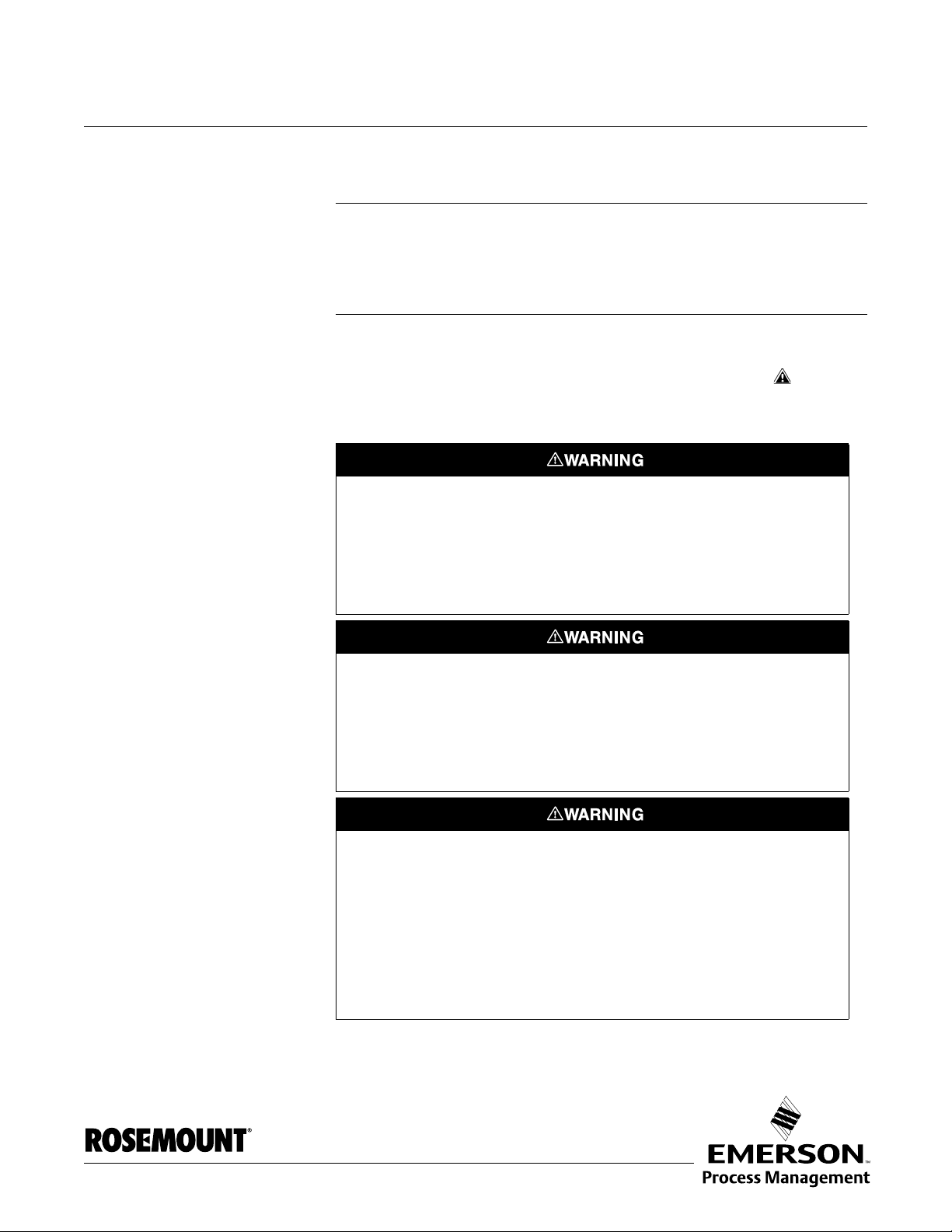
SAFETY MESSAGES Procedures and instructions in this manual may require special precautions to
ensure the safety of the personnel performing the operations. Information that
raises potential safety issues is indicated by a warning symbol ( ). Refer to
the safety messages listed at the beginning of each section before performing
an operation preceded by this symbol.
Failure to follow these installation guidelines could result in death or serious
injury.
• Make sure only qualified personnel perform the installation.
• Use the equipment only as specified in this manual. Failure to do so may
impair the protection provided by the equipment.
Explosions could result in death or serious injury.
• Verify that the operating environment of the transmitter is consistent with the
appropriate hazardous locations certifications.
• Before powering a F
make sure the instruments in the loop are installed in accordance with
intrinsically safe or non-incendive field wiring practices.
Electrical shock could cause death or serious injury.
• Use extreme caution when making contact with the leads and terminals.
OUNDATION fieldbus segment in an explosive atmosphere,
www.rosemount.com
Any substitution of non-recognized parts may jeopardize safety. Repair, e.g. substitution
of components etc., may also jeopardize safety and is under no circumstances allowed.
Page 12

Reference Manual
00809-0100-4032, Rev AA
Rosemount 5400 Series
November 2005
MANUAL OVERVIEW This manual provides installation, configuration and maintenance information
for the Rosemount 5400 Series Radar Transmitter.
Section 2: Transmitter Overview
• Theory of Operation
• Descripton of the transmitter
• Process and vessel characteristics
Section 3: Installation
• Mounting considerations
• Mechanical installation
• Electrical installation
Section 4: Configuration/Start-Up
• Configuration instructions
• Configuration using DeltaV
• Configuration using the RRM software
Section 5: Operation
• Viewing measurement data with a Display panel
• Viewing measurement data with Rosemount Radar Master
Section 6: Service and Troubleshooting
• Service Functions
• Error and Warning Codes
• Communication Errors
• Troubleshooting
Appendix A: Reference Data
• Specifications
• Dimensional Drawings
• Ordering Information
Appendix B: Product Certifications
• Examples of labels
• European ATEX Directive information
• FM approvals
• CSA approvals
•Drawings
1-2
Appendix C: Advanced Configuration
• Advanced Tank Geometry
• Advanced Transmitter Configuration
Appendix D: Level Transducer Block
Describes the operation and parameters of the Level transducer block.
Appendix E: Register Transducer Block
Describes the operation and parameters of the Register transducer block.
Page 13

Reference Manual
00809-0100-4032, Rev AA
November 2005
Appendix F: Advanced Configuration Transducer Block
Describes the operation and parameters of the Advanced Configuration
transducer block.
Appendix G: Resource Transducer Block
Describes the operation and parameters of the Resource transducer
block.
Appendix H: Analog-Input Transducer Block
Describes the operation and parameters of the Analog Input transducer
block.
Rosemount 5400 Series
SERVICE SUPPORT To expedite the return process outside of the United States, contact the
nearest Rosemount representative.
Within the United States, call the Rosemount National Response Center using
the 1-800-654-RSMT (7768) toll-free number. This center, available 24 hours
a day, will assist you with any needed information or materials.
The center will ask for product model and serial numbers, and will provide a
Return Material Authorization (RMA) number. The center will also ask for the
process material to which the product was last exposed.
Rosemount National Response Center representatives will explain the
additional information and procedures necessary to return goods exposed to
hazardous substance can avoid injury if they are informed of and understand
the hazard. If the product being returned was exposed to a hazardous
substance as defined by Occupational Safety and Health Administration
(OSHA), a copy of the required Material Safety Data Sheet (MSDS) for each
hazardous substance identified must be included with the returned goods.
1-3
Page 14

Rosemount 5400 Series
Reference Manual
00809-0100-4032, Rev AA
November 2005
1-4
Page 15
Reference Manual
00809-0100-4032, Rev AA
November 2005
Rosemount 5400 Series
Section 2 Transmitter Overview
Theory of Operation . . . . . . . . . . . . . . . . . . . . . . . . . . . . . . page 2-1
Components of the transmitter . . . . . . . . . . . . . . . . . . . . . page 2-2
System Architecture . . . . . . . . . . . . . . . . . . . . . . . . . . . . . . page 2-3
Antenna Selection Guide/Measuring Range . . . . . . . . . . page 2-5
Process Characteristics . . . . . . . . . . . . . . . . . . . . . . . . . . . page 2-4
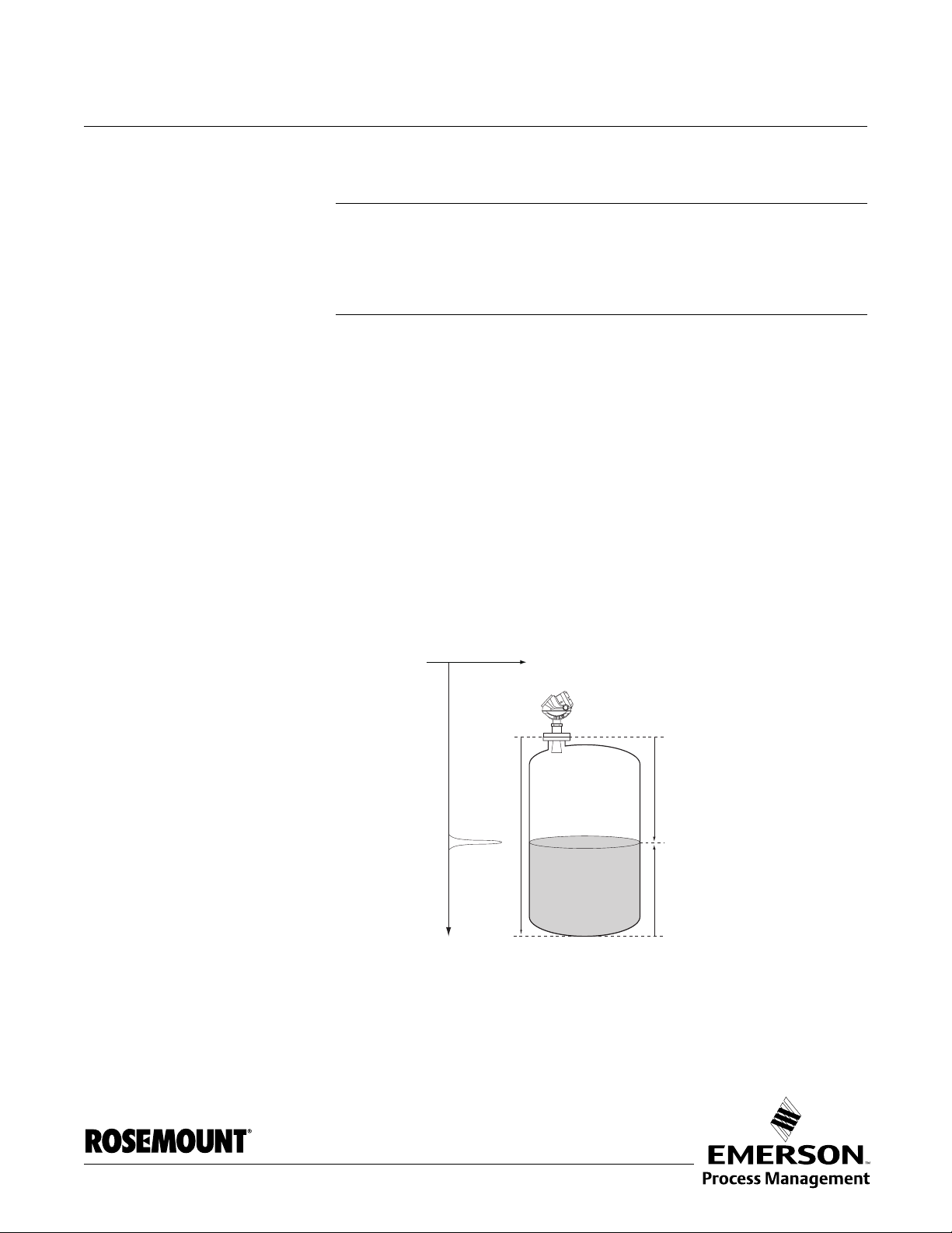
THEORY OF OPERATION The Rosemount 5400 Series Radar Transmitter is a smart, two-wire
continuous level transmitter. A 5400 transmitter is installed at the tank top and
emits short microwave pulses towards the product surface in the tank. When
a pulse reaches the surface of the material it is measuring, part of the energy
is reflected back to the antenna for subsequent processing by the transmitter
electronics. The time difference between the transmitted and reflected pulse
is detected by a micro-processor and is converted into a distance from which
the level is calculated.
The product level is related to the tank height and the measured distance by
the following expression:
Figure 2-1. Measurement
principle for the 5400 Series.
Level=Tank Height - Distance.
Signal amplitude
Tank Height
Radar pulse
Time
Distance
Level
TDR_PRINCIPLES(2).EPS
www.rosemount.com
Page 16
Rosemount 5400 Series
Reference Manual
00809-0100-4032, Rev AA
November 2005
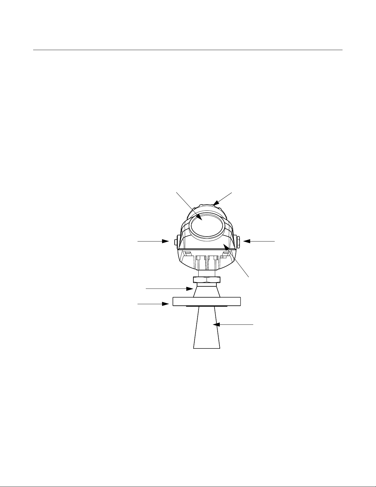
COMPONENTS OF THE TRANSMITTER
Figure 2-2. Transmitter
components.
Cable Entry:
½" NPT.
Optional adapters: M20
The Rosemount 5400 Series Radar Transmitter has a die-cast aluminum
housing which contains advanced electronics for signal processing.
The radar electronics produces the electromagnetic pulse that is emitted
through the antenna. There are different antenna types and sizes available for
various applications.
The transmitter head has separate compartments for electronics and
terminals. The head can be removed without opening the tank. The head has
two entries for conduit/cable connections.
The tank connection consists of a Tank Seal and a flange
(ANSI, EN (DIN) or JIS).
Display Panel Terminal side
Cable Entry:
½" NPT.
Optional adapters: M20
Transmitter Head with
Tank Seal
Flange
TRANSMITTER_COMPONENTS.EPS
Radar Electronics
Antenna
2-2
Page 17
Reference Manual
00809-0100-4032, Rev AA
November 2005
Rosemount 5400 Series
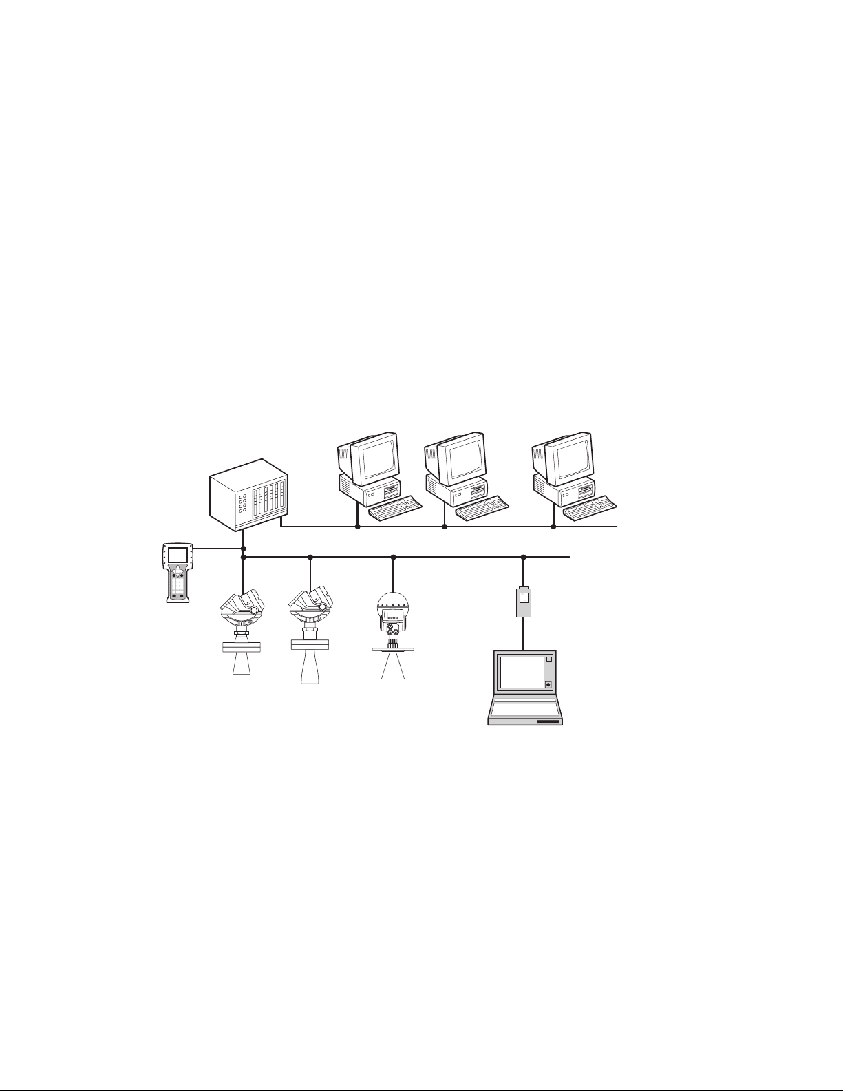
SYSTEM ARCHITECTURE
Figure 2-3. System Integration.
F
OUNDATION™
fieldbus
The 5400 Series Radar Level Transmitter is a powerful radar level transmitter
suitable for non-contact level measurements in process tanks and other types
of tanks. It is designed for easy installation and maintenance free operation.
The Rosemount 5400 Series Radar Transmitter is loop-powered which
means it uses the same two wires for both power supply and F
fieldbus signal. For HART
®
based systems the output is a 4-20 mA analog
OUNDATION
TM
signal superimposed with a digital HART signal.
The Rosemount 5400 Series Radar Transmitter can easily be configured by
using a PC and the Rosemount Radar Master (RRM) software package or via
a 375 Field Communicator. RRM offers configuration and service capabilities
and functions for presentation of measurement data. The transmitter is also
compatible with the AMS
™
Suite software which can be used for
configuration.
Host / DCS system (e.g. DeltaV) Maintenance
H2 - High Speed Field Bus
375 Field
Communicator
Note:
Intrinsically safe
installations may allow
fewer devices per I.S.
barrier due to current
limitations.
Rosemount
5401
Rosemount
5402
Rosemount
5601
Fieldbus Modem
H1 - Low Speed Field Bus
6234 ft (1900 m) max
(depending upon cable
characteristics)
Configuration with
RadarMaster (hooked up on
Fieldbus segment)
FF.EPS
2-3
Page 18

Rosemount 5400 Series
PROCESS CHARACTERISTICS
Reference Manual
00809-0100-4032, Rev AA
November 2005
Dielectric constant
The reflectivity of the product is a key parameter for measurement
performance. A high dielectric constant of the media gives better reflection
and thus enables a longer measuring range.
Foam How well the Rosemount 5400 Series Radar Transmitter measures in foamy
applications depends upon the properties of the foam; light and airy or dense
and heavy, high or low dielectrics, etc. If the foam is conductive and creamy
the transmitter will probably measure the surface of the foam. If the foam is
less conductive the microwaves will probably penetrate the foam and
measure the liquid surface.
Turbulence A calm surface gives better reflection than a turbulent surface. For turbulent
applications, the maximum range of the radar transmitters is reduced. The
range is dependent upon the frequency, the antenna size, the dielectric of the
material and the degree of turbulence. Consult Table 2-1 on page 2-5 and
Table 2-2 on page 2-5 for the expected maximum range with the variables
listed.
Temperature/Pressure/ Density and Vapor
Temperature and pressure generally have no impact on measurements.
Measurements are also insensensitive to product density and vapor.
Condensation For applications where heavy condensation may occur the low frequency
version Rosemount 5401 is recommended.
Tank Characteristics The conditions inside the tank have a significant impact on measurement
performance. For more information see Vessel Characteristics on page 3-8.
2-4
Page 19
Reference Manual
00809-0100-4032, Rev AA
November 2005
Rosemount 5400 Series
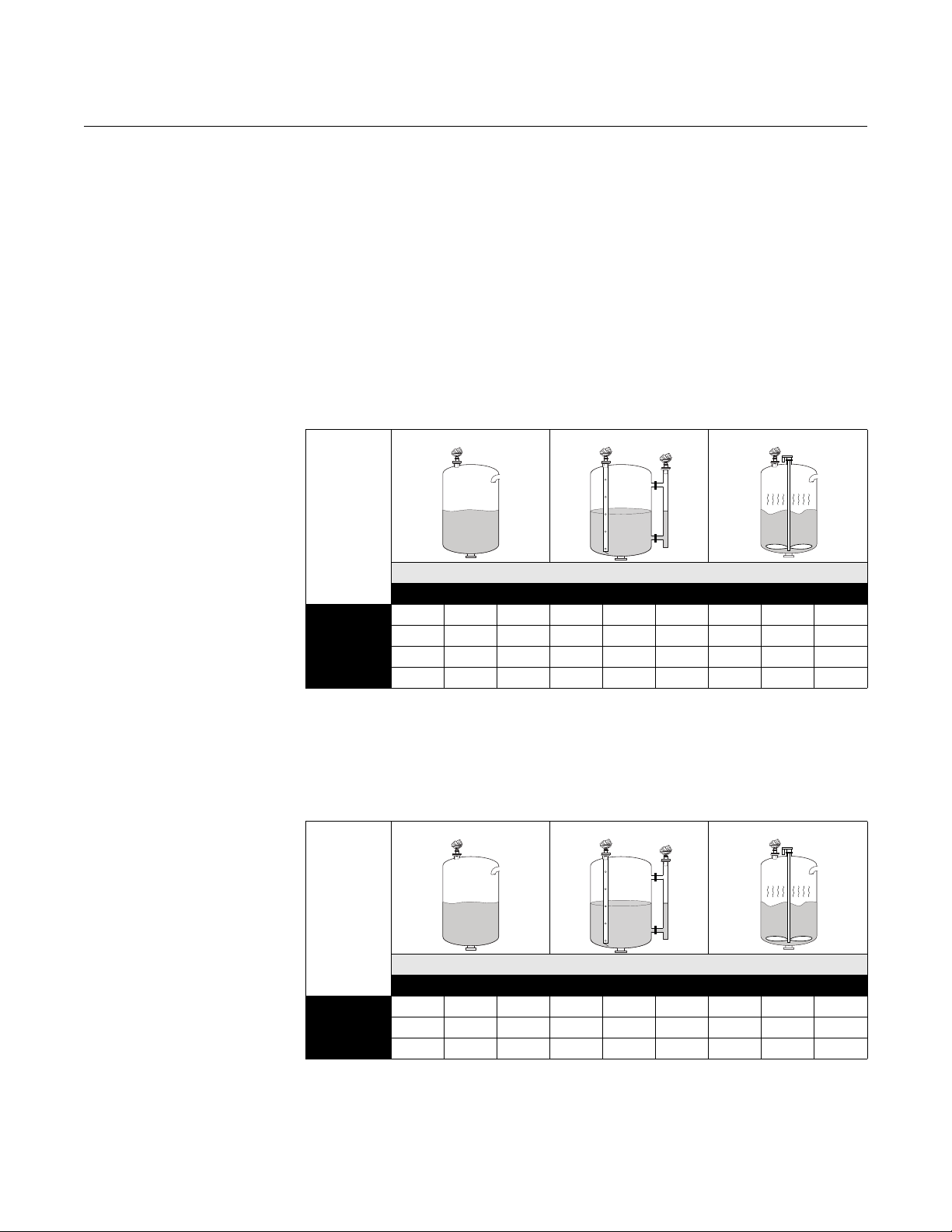
ANTENNA SELECTION GUIDE/MEASURING RANGE
Table 2-1. Measuring range for
the Rosemount 5401 model.
The measuring range primarily depends on the antenna type and size, the
dielectric constant (ε
) of the liquid and process conditions. For optimum
r
performance, make sure not to exceed the maximum measuring range values
below.
A. Oil, gasoline and other hydrocarbons, petrochemicals (ε
=1.9-4.0).
r
B. Alcohols, concentrated acids, organic solvents, oil/water mixtures and
acetone (ε
=4.0-10.0).
r
C. Conductive liquids, e.g. water based solutions, dilute acids and alkalis
(ε
>10.0).
r
Low
Frequency
Antennas
Units: feet (m)
Dielectric Constant
A B C A B C A B C
(1)
Cone, 3 in
Cone, 4 in/Rod
Cone, 6 in
Cone, 8 in
(1) Pipe installations only. NA=Not Applicable.
NA NA NA 66 (20) 66 (20) 66 (20) NA NA NA
20 (6) 33 (10) 43 (13) 66 (20) 66 (20) 66 (20) 9.9 (3) 16 (5) 23 (7)
33 (10) 49 (15) 66 (20) 66 (20) 66 (20) 66 (20) 16 (5) 23 (7) 30 (9)
49 (15) 66 (20) 98 (30) 66 (20) 66 (20) 98 (30) 23 (7) 30 (9) 36 (11)
Table 2-2. Measuring range for
the Rosemount 5402 model.
High
Frequency
Antennas
Units: feet (m)
Cone, 2 in
Cone, 3 in
Cone, 4 in
Dielectric Constant
A B C A B C A B C
16 (5) 33 (10) 49 (15) 66 (20) 66 (20) 66 (20) 6.6 (2) 9.8 (3) 13 (4)
33 (10) 49 (15) 66 (20) 66 (20) 66 (20) 66 (20) 9.8 (3) 13 (4) 20 (6)
49 (15) 66 (20) 98 (30) 66 (20) 66 (20) 98 (30) 13 (4) 20 (6) 26 (8)
2-5
Page 20

Rosemount 5400 Series
Reference Manual
00809-0100-4032, Rev AA
November 2005
2-6
Page 21
Reference Manual
00809-0100-4032, Rev AA
November 2005
Rosemount 5400 Series
Section 3 Installation
Safety Messages . . . . . . . . . . . . . . . . . . . . . . . . . . . . . . . . . page 3-1
Installation Procedure . . . . . . . . . . . . . . . . . . . . . . . . . . . . page 3-2
Mounting Considerations . . . . . . . . . . . . . . . . . . . . . . . . . page 3-3
Mechanical Installation . . . . . . . . . . . . . . . . . . . . . . . . . . . page 3-9
Electrical Installation . . . . . . . . . . . . . . . . . . . . . . . . . . . . . page 3-13
SAFETY MESSAGES Procedures and instructions in this section may require special precautions to
ensure the safety of the personnel performing the operations. Information that
raises potential safety issues is indicated by a warning symbol ( ). Please
refer to the following safety messages before performing an operation
preceded by this symbol.
Explosions could result in death or serious injury:
Verify that the operating environment of the transmitter is consistent with the appropriate
hazardous locations certifications.
Before powering a F
sure the instruments in the loop are installed in accordance with intrinsically safe or
non-incendive field wiring practices.
Do not remove the gauge cover in explosive atmospheres when the circuit is alive.
OUNDATION fieldbus segment in an explosive atmosphere, make
Failure to follow safe installation and servicing guidelines could result in death or
serious injury:
Make sure only qualified personnel perform the installation.
Use the equipment only as specified in this manual. Failure to do so may impair the
protection provided by the equipment.
Do not perform any service other than those contained in this manual unless you are
qualified.
High voltage that may be present on leads could cause electrical shock:
Avoid contact with leads and terminals.
Make sure the main power to the 5400 transmitter is off and the lines to any other
external power source are disconnected or not powered while wiring the gauge.
To prevent ignition of flammable or combustible atmospheres, disconnect power before
servicing.
Antennas with non-conducting surfaces (e.g. Rod antenna and All PTFE antenna) may
generate an ignition-capable level of electrostatic charge under extreme conditions.
Therefore, when the antenna is used in a potentially explosive atmoshpere, appropriate
measures must be taken to prevent electrostatic discharge.
www.rosemount.com
Page 22
Rosemount 5400 Series
Reference Manual
00809-0100-4032, Rev AA
November 2005
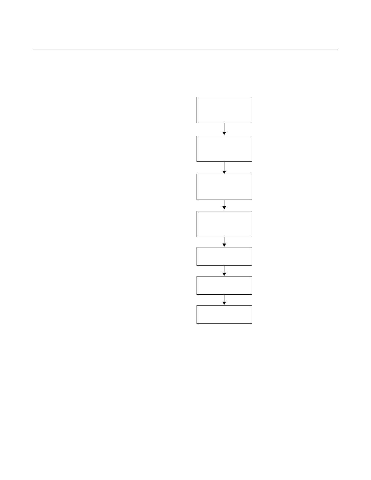
INSTALLATION PROCEDURE
Follow these steps for proper installation:
Review Installation
Considerations
(see page 3-3)
Mount the transmitter
(see page 3-9)
Wire the transmitter
(see page 3-13)
Make sure covers
and cable/conduit
connections are
tight.
Power Up the
transmitter
Configure the
transmitter
(see page 4-1)
Verify measurements
3-2
Page 23
Reference Manual
00809-0100-4032, Rev AA
November 2005
Rosemount 5400 Series
MOUNTING CONSIDERATIONS
Before you install the Rosemount 5400 Series, be sure to consider specific
mounting requirements, vessel characteristics and process characteristics.
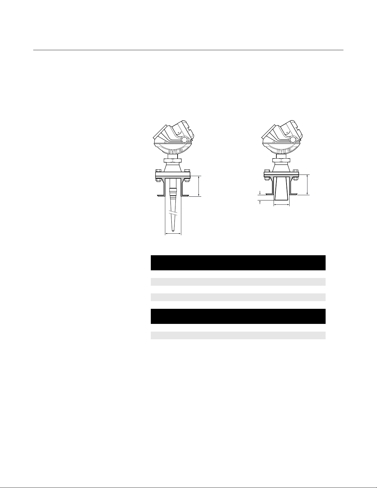
Socket Recommendation The Rosemount 5400 Series is mounted on a nozzle by using appropriate
flanges. For best performance it is recommended that the socket meets the
following recommendations:
Figure 3-1. Mounting of the 5400
Series transmitter.
L
>0.4 inch/
10 mm
Minimum Diameter
Minimum Diameter
L
SOCKETREQ ROD.EPS/SOCKETREQ.EPS
Table 3-1. Requirements on
socket height and width.
5401 Antenna L
Cone 4 in. 5.5 (140) 3.8 (97)
Cone 6 in. 6.9 (175) 5.7 (145)
Cone 8 in. 10.2 (260) 7.6 (193)
Rod (short) 4.0 (100) 1.5 (38)
Rod (long) 10 (250) 1.5 (38)
5402 Antenna L
Cone 2 in. 5.5 (140) 2.2 (55)
Cone 3 in. 5.5 (140) 2.8 (72)
Cone 4 in. 8.5 (215) 3.8 (97)
inch (mm)
max
inch (mm)
max
Min. Diameter
inch (mm)
Min. Diameter
inch (mm)
The transmitter should be installed as follows:
• The antenna must be aligned vertically.
• Choose as large antenna diameter as possible. A larger receiving area
concentrates the radar beam and ensures maximum antenna gain.
Increased antenna gain means greater margin for weak surface
echoes. A larger antenna also results in a smaller beam angle and
thereby, less interference from any internal obstructions.
• For best measurement performance, the antenna should extend below
the nozzle by 0.4 inches (10 mm) or more.
• For the 5402 model 3-in. and 4-in. antennas can be used in nozzles
with an unobstructed length of up to 39 in. (1 m). The 2-in. antenna
may be used in nozzles where the total length is less than 12 in.
(0.3) m.
3-3
Page 24
Reference Manual
00809-0100-4032, Rev AA
Rosemount 5400 Series
November 2005
Free Space For easy access to the transmitter make sure that it is mounted with sufficient
service space.
Mounting close to a tank wall, nozzle or obstruction may have a negative
influence on measurement perfomance. For maximum measurement
performance the transmitter should be mounted according to the following
recommendations:
Figure 3-2. Free space
recommendations.
Rod Antenna Cone Antenna
A
B
D
Service space Distance inch (mm)
A 20 (500)
B 24 (600)
C. Inclination Maximum angle
Cone antenna 3°
D. Minimum distance to tank wall Distance inch (mm)
Cone antenna 5401 20 (500)
Cone antenna 5402 10 (250)
Rod antenna 5401 20 (500)
C
D
FREESPACE_ROD.EPS/FREESPACE.EPS
3-4
Page 25
Reference Manual
00809-0100-4032, Rev AA
November 2005
Rosemount 5400 Series
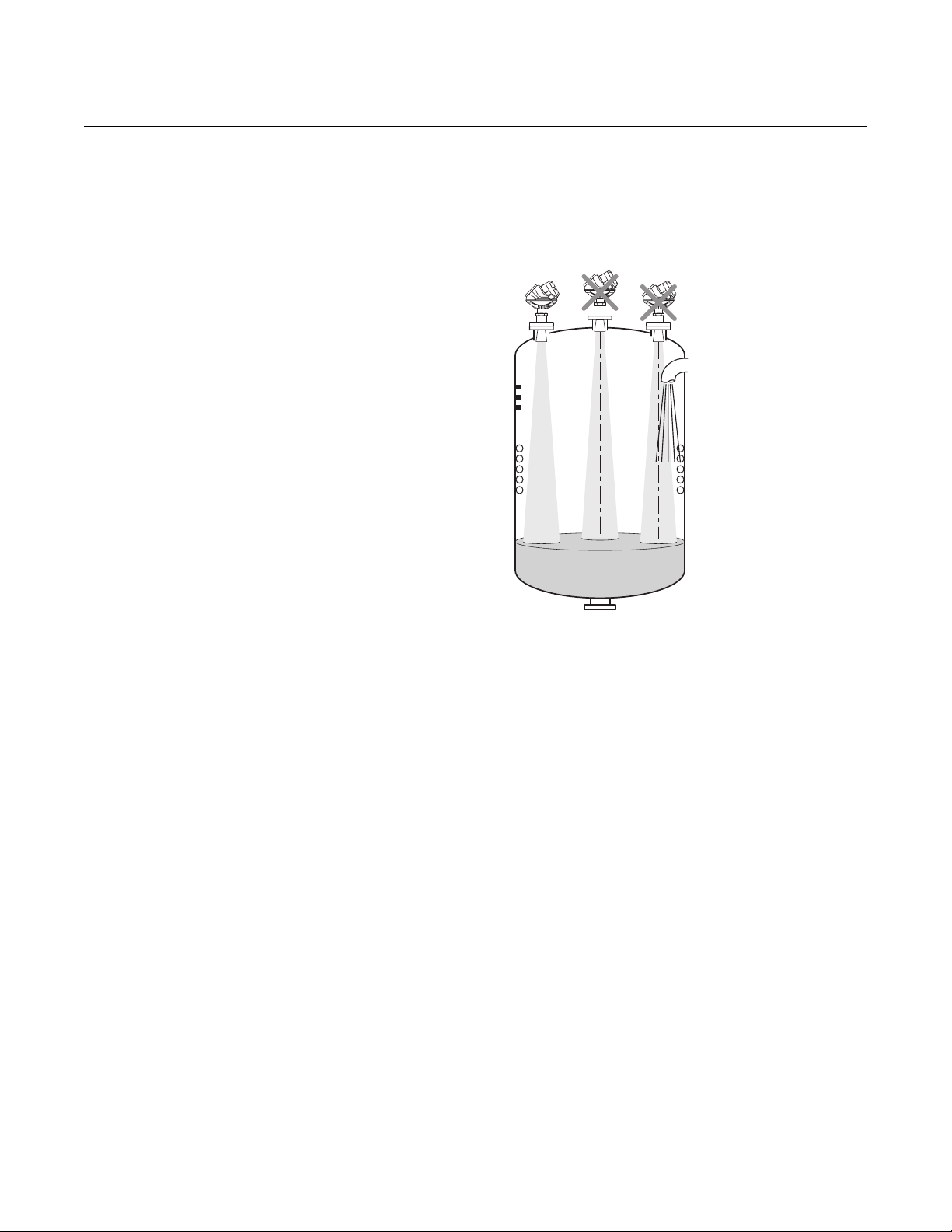
Recommended Mounting Position
Figure 3-3. It is important to
consider the proper mounting
position.
When finding an appropriate mounting position for the transmitter the
conditions of the tank must be carefully considered. The transmitter should be
mounted so that the influence of disturbing objects is kept to a minimum.
MOUNTING_RESTRICTIONS.EPS
• Disturbing objects and filling inlets creating turbulence should be kept
at a distance, outside the signal beam (see Figure 3-4 for beam width
information).
• Avoid installing the transmitter at the center of the tank roof.
• A bridle / still-pipe can be used to avoid interference from disturbing
objects, turbulence or foam.
3-5
Page 26
Reference Manual
00809-0100-4032, Rev AA
Rosemount 5400 Series
November 2005
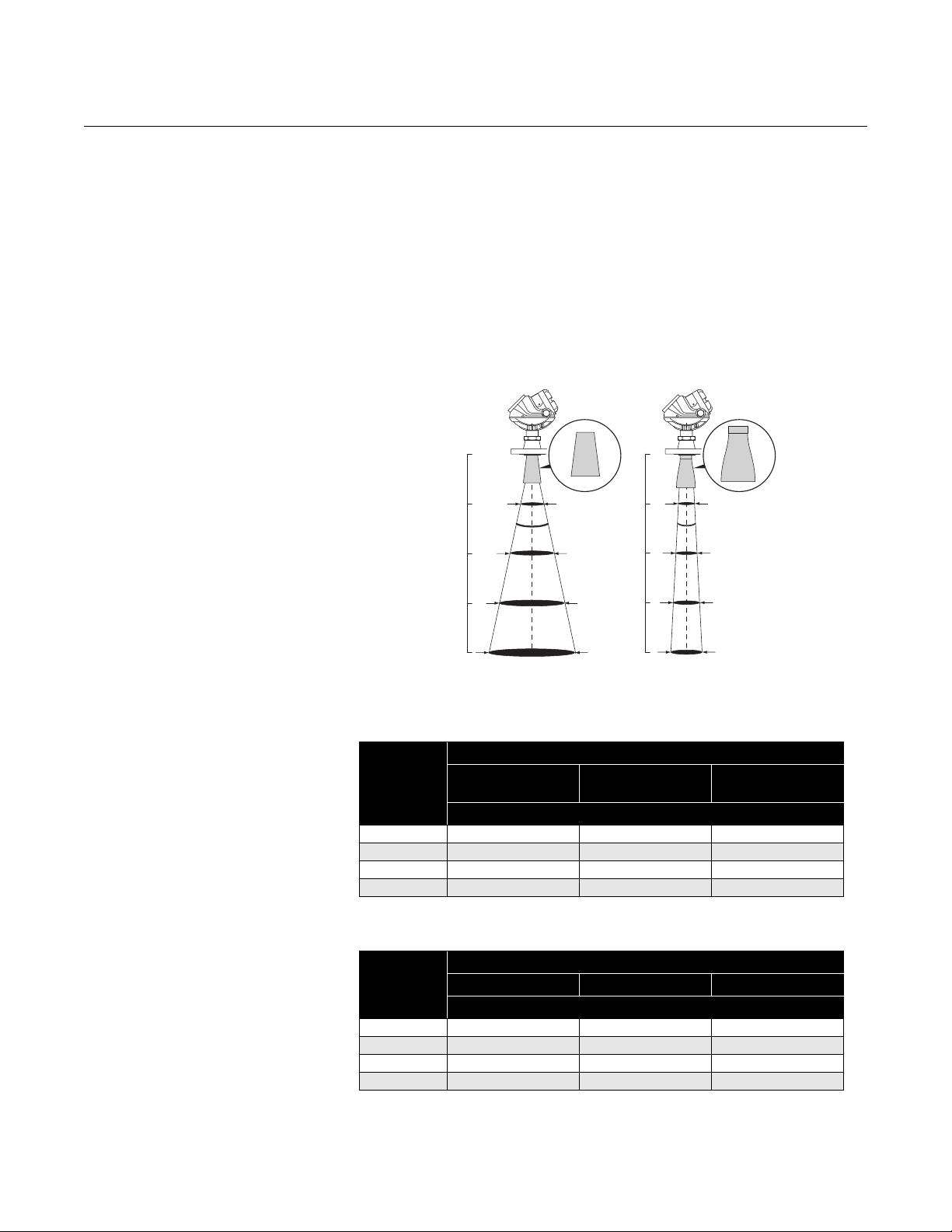
Beam Width The following recommendations should be considered when mounting the
transmitter:
• The transmitter should be mounted with as few internal structures as
possible within the beam angle.
• The flat tank wall can be located within the antenna beam angle as long
as there is a minimum distance from the transmitter to the tank wall
(see Figure 3-2 for preferred installation).
Figure 3-4. Beam width at
various distances from the
flange.
5401
(low frequency)
5402
(high frequency)
Table 3-2. Beamwidth for the
Rosemount 5401 model.
Table 3-3. Beamwidth for the
Rosemount 5402 model.
Distance
Antenna
Distance
16 ft (5 m) 11.5 (3.5) 6.6 (2.0) 4.9 (1.5)
33 ft (10 m) 23.0 (7.0) 13.1 (4.0) 9.8 (3.0)
49 ft (15 m) 32.8 (10) 19.7 (6.0) 14.8 (4.5)
66 ft (20 m) 42.7 (13) 26.2 (8.0) 19.7 (6.0)
Distance
16 ft (5 m) 4.9 (1.5) 3.3 (1.0) 3.3 (1.0)
33 ft (10 m) 9.8 (3.0) 6.6 (2.0) 4.9 (1.5)
49 ft (15 m) 14.8 (4.5) 9.8 (3.0) 8.2 (2.5)
66 ft (20 m) 19.7 (6.0) 13.1 (4.0) 9.8 (3.0)
4 in. (DN 100) Cone
/Rod
2 in. (DN 50) Cone 3 in. (DN 80) Cone 4 in. (DN 100) Cone
6 in. (DN 150) Cone 8 in. (DN 200) Cone
Beam Diameter, ft (m)
Antenna
Beam Diameter, ft (m)
BEAM_DIAMETER_2.EPS
3-6
Page 27
Reference Manual
00809-0100-4032, Rev AA
November 2005
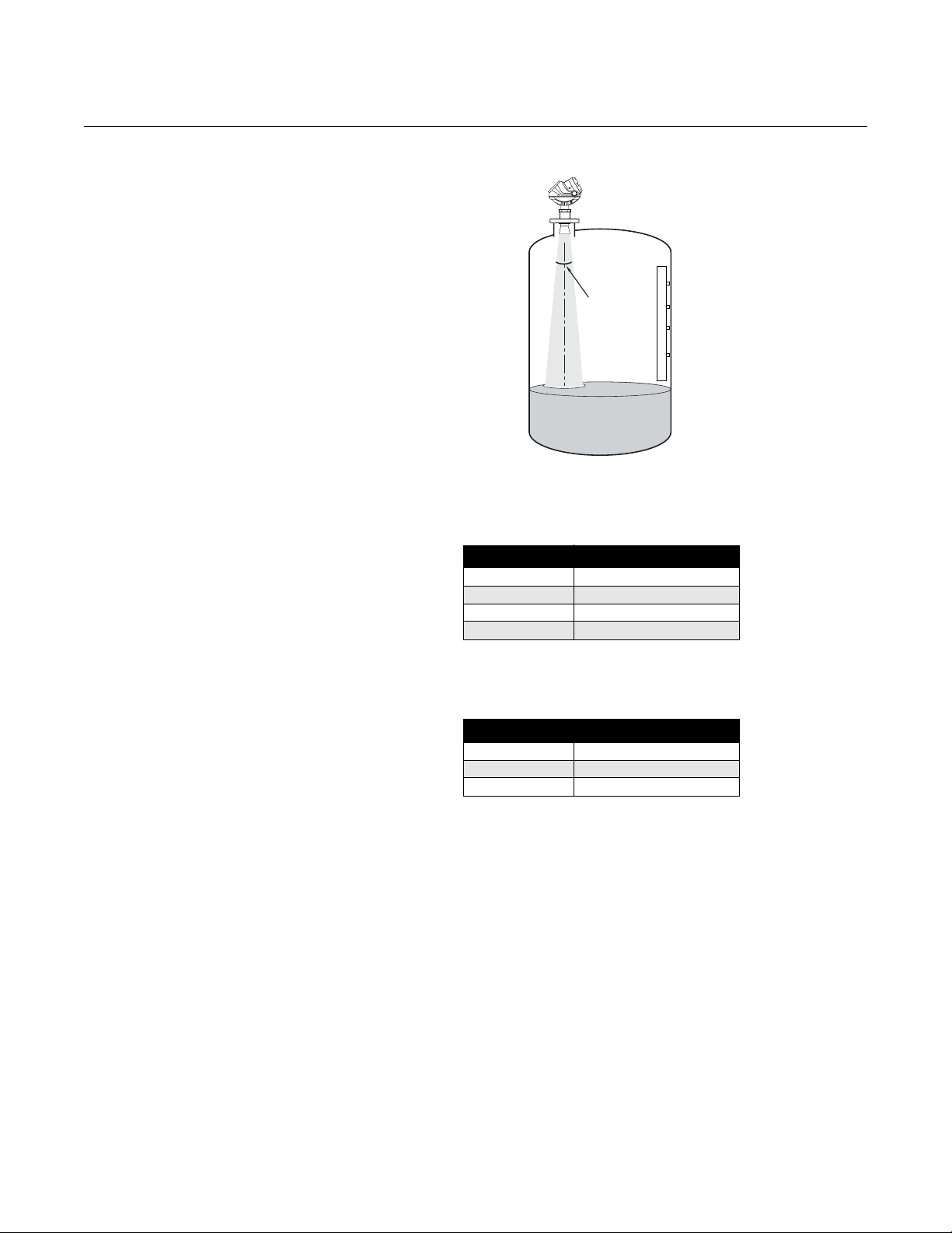
Figure 3-5. Beam angle.
Rosemount 5400 Series
Beam Angle
BEAMWIDTH2.EPSS
Table 3-4. Beam Angle for the
Rosemount 5401 model.
Table 3-5. Beam Angle for the
Rosemount 5402 model.
Antenna Half Power Beam Width
3 in. Cone (Still Pipe)
4 in. Cone / Rod 37°
6 in. Cone 23°
8 in. Cone 17°
Antenna Half Power Beam Width
2 in. Cone 19°
3 in. Cone 14°
4 in. Cone 9°
3-7
Page 28

Reference Manual
00809-0100-4032, Rev AA
Rosemount 5400 Series
November 2005
Vessel Characteristics Heating coils, agitators and other objects in the tank may lead to disturbing
echoes and noise in the measurement signal. Vertical structures cause
minimal effect since the radar signal is scattered rather than directed back to
the antenna.
The shape of the tank bottom affects the measurement signal when the
product surface is close to the tank bottom. The Rosemount 5400 Series has
built-in functions which optimize measurement performance for various
bottom shapes (see Tank Type and Tank Bottom Type on page 4-7).
Disturbing objects The Rosemount 5400 Series transmitter should be mounted so that objects
such as heating coils, ladders etc. are not within the radar signal path. These
objects may cause false echoes resulting in reduced measurement
performance. However, the transmitter has built-in functions designed to
reduce the influence of disturbing objects in case such objects can not be
totally avoided.
The Rosemount 5402 with its more narrow radar beam is particularly suitable
in installations that have tall or narrow nozzles or nozzles close to the tank
wall. It may also be used to avoid disturbing objects in the tank.
3-8
Page 29
Reference Manual
00809-0100-4032, Rev AA
November 2005
Rosemount 5400 Series
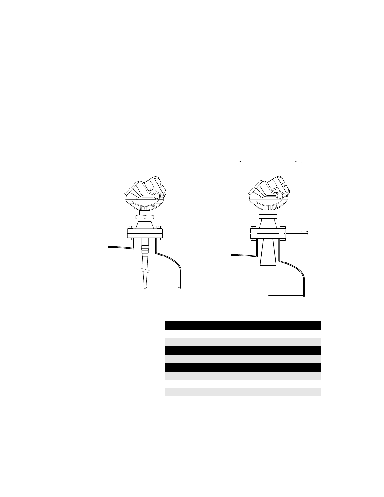
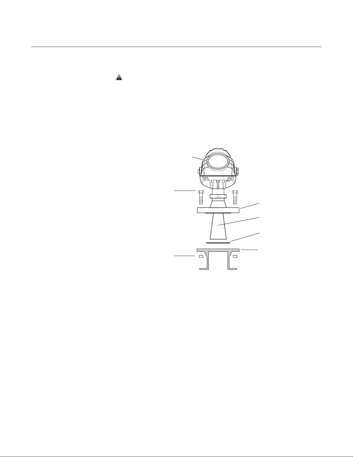
MECHANICAL INSTALLATION
Figure 3-6. Mounting the 5400
with cone antenna.
Mount the transmitter on a nozzle on top of the tank. Make sure only qualified
personnel perform the installation.
The transmitter housing must not be opened. If a software update or other
service action is required that involves opening the housing, it must be done
by a suitably trained service technician. Maintenance work that involves
opening the housing must not be done when the transmitter is mounted on the
tank.
If the transmitter housing must be removed for service, make sure that the
®
Te fl o n
sealing is carefully protected against dust and water.
Transmitter housing
Bolt
Flange
Cone antenna
Gasket
Tan k f lange
Nut
1. Place a gasket with thickness and of material suitable to the process on
top of the tank flange.
2. Lower the transmitter with antenna and flange into the tank nozzle.
3. Tighten the bolts and nuts with sufficient torque regarding flange and
gasket choice. See also Process Temperature and Pressure Rating on
page A-4.
MOUNT_TH_FLANGE.EPS
3-9
Page 30
Rosemount 5400 Series
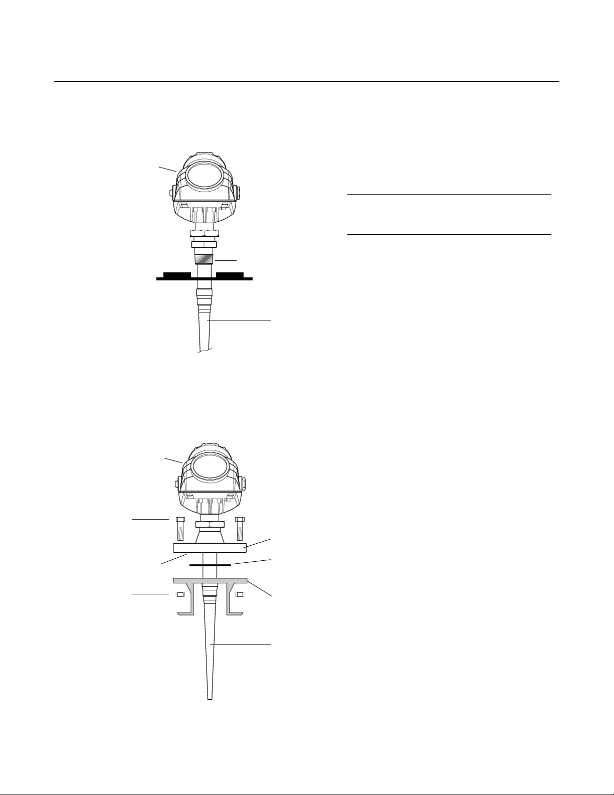
Figure 3-7. Mounting the 5400
transmitter with rod antenna and
threaded tank connection.
Transmitter housing
Reference Manual
00809-0100-4032, Rev AA
November 2005
1. Lower the transmitter and antenna into
the tank.
2. Screw the transmitter into the process
connection.
NOTE!
Tank connections with NPT threads require a
sealant for pressure-tight joints.
Sealant on threadsSealant on threads
Antenna
MOUNT_TH_ROD_THREADED.EPS
Figure 3-8. Mounting the 5400
transmitter with rod antenna and
flange connection.
Transmitter housing
Optional PFA plate
Bolt
Nut
Flange
Gasket (not for
the All PFA
version)
Tank flan ge
1. Place a gasket with thickness and of
material suitable to the process on top of
the tank flange.
Note: For the All PFA version (tank
sealing model code=PD) no gasket is
used.
2. Lower the transmitter with antenna and
flange into the tank nozzle.
3. Tighten the bolts and nuts with sufficient
torque regarding flange and gasket
choice. See also Process Temperature
and Pressure Rating on page A-4.
3-10
MOUNT_ROD_FLANGE.EPS
Rod antenna
Page 31

Reference Manual
00809-0100-4032, Rev AA
November 2005
Rosemount 5400 Series
Mounting in Pipes Still Pipe mounting is recommended for tanks where surface conditions are
extremely turbulent. All cone antenna sizes for the 5400 Series transmitter
can be used for Still Pipe installations. The 2 and 3 inch antennas for 5401 are
designed for use in Still Pipes and Bypass Pipes only.
When the transmitter is mounted in a Still Pipe the inclination should be
within 1° of vertical. The gap between the antenna and the Still Pipe may be
up to 0.2 inch (5 mm).
Figure 3-9. Mount the
transmitter vertically.
max. 0.2 inch
(5 mm)
Figure 3-10. Recommended
hole size for pipe installations.
max. 1 °
STILLPIPE_REQS.EPS / STILLPIPE_TANK_V2.EPS
Recommendations for pipe installations
• The pipe must be smooth on the inside.
• Not suitable for adhesive products.
• Make sure that at least one hole is above the product surface.
• The hole diameter Ø should not exceed 10% of the pipe diameter D.
• Holes should be drilled on one side.
min. 6 inch (150 mm)
max. Ø: D/10.
STILLPIPE_HOLEREQ.EPS
D
3-11
Page 32

Rosemount 5400 Series
Reference Manual
00809-0100-4032, Rev AA
November 2005
Mounting in Bypass Pipes
Figure 3-11. Bridle mounting is
recommended for tanks with
extremely turbulent surface
conditions.
In tanks with turbulent conditions it is recommended to mount the transmitter
on a bridle pipe.
BRIDLE_V2.EPS
max. 1 °
Minimum 12 in. (300 mm)
In pipes with inlet pipe diameter Ø<2 inch (51 mm) the gap D between pipe
and antenna should be less than 0.2 inch (5 mm).
Figure 3-12. Recommended
specifications for bridles with
pipe inlets.
If the inlet pipe diameter Ø>2 inch (51 mm) the gap D between pipe and
antenna should be less than 0.04 inch (1 mm).
The distance A between the antenna and the nearest inlet pipe should be at
least 2 inches (50 mm).
Ø (in./mm) D (in./mm)
<2/51 <0.2/5
>2/51 <0.04/1
A > 2 in./50 mm
D
Ø
BRIDLE_REQUIREMENTS.EPS
3-12
Page 33

Reference Manual
00809-0100-4032, Rev AA
November 2005
Rosemount 5400 Series
ELECTRICAL INSTALLATION
Cable/conduit entries The electronics housing has two entries with ½ - 14 NPT threads. Optional
M20×1.5 adapters are also available. The connections are made in
accordance with national, local and plant electrical codes.
Make sure that unused ports are properly sealed to prevent moisture or other
contamination from entering the terminal compartment of the electronics
housing. Install wiring with a drip loop. The bottom of the loop must be lower
than the cable/conduit entry.
NOTE!
Use the enclosed metal plug to seal any unused port.
Grounding The housing should always be grounded in accordance with national and
local electrical codes. Failure to do so may impair the protection provided by
the equipment. The most effective grounding method is direct connection to
earth ground with minimal impedance. There are two grounding screw
connections provided. One is inside the Terminal compartment of the housing
and the other is located on one of the cooling fins below the housing. The
internal ground screw is identified by a ground symbol: .
NOTE!
Grounding the transmitter via threaded conduit connection may not provide
sufficient ground.
NOTE!
After installation and commissioning make sure that no ground currents exist
due to high ground potential differences in the installation.
Cable Selection For best installation practices use a fieldbus type A cable. All power to the
transmitter is supplied over the signal wiring. For the Rosemount 5400 Series
signal wiring should be shielded, twisted pair for best results in electrically
noisy environments. Do not use unshielded signal wiring in open trays with
power wiring or near heavy electrical equipment. The cables must be suitable
for the supply voltage and approved for use in hazardous areas, where
applicable. For instance, in the U.S., explosionproof conduits must be used in
the vicinity of the vessel. For the ATEX flameproof approval version of the
Rosemount 5400 Series, suitable conduits with sealing device or flameproof
(EEx d) cable glands must be used depending on local requirements.
Use 18 AWG to 12 AWG wiring in order to minimize the voltage drop to the
transmitter.
Do not remove the transmitter cover in explosive atmospheres when the
circuit is alive.
Hazardous Areas When the Rosemount 5400 Series transmitter is installed in hazardous area,
national and local regulations and specifications in applicable certificates
must be observed.
3-13
Page 34

Reference Manual
00809-0100-4032, Rev AA
Rosemount 5400 Series
November 2005
External Circuit Breaker For complicance with Low Voltage Directive 73/23/EEG an external circuit
breaker should be installed.
Power Requirements Terminals in the transmitter housing provide connections for signal wiring.
The 5400 transmitter is powered over F
fielbus power supplies.
The transmitter operates with the following power supplies:
Approval Type Power Supply (V dc)
IS 9 - 30
Explosion Proof/Flame Proof 16 - 32
None 9 - 32
OUNDATION fieldbus with standard
3-14
Page 35

Reference Manual
00809-0100-4032, Rev AA
November 2005
Rosemount 5400 Series
Connecting the Transmitter
Figure 3-13. Terminal
compartment and external
ground screw.
The Rosemount 5400 Series with Foundation Fieldbus accepts power
supplies ranging from 9 V dc to 32 V dc.
To connect the transmitter:
1. Make sure that the power supply is switched off.
2. Remove the terminal block cover.
3. Pull the cable through the cable gland/conduit. Install wiring with a drip
loop. The bottom of the loop must be lower than the cable/conduit entry.
4. Connect wires according to Figure 3-15 for non-intrinsically safe power
supplies and according to Figure 3-16 for Intrinsically safe power
supplies.
5. Use the enclosed metal plug to seal any unused port.
6. Mount the cover and tighten the cable gland. Make sure that the cover is
fully engaged to meet explosion-proof requirements.
Note that adapters are required if M20 glands are used.
7. Tighten the Locking Screw (ATEX Flameproof version).
8. Switch on the power supply.
NOTE!
Use Teflon® tape or other sealant at the NPT threads in the Cable Entries.
3
5
11
4
2
GROUNDINGSCREW.EPS/JUNCTION_BOX.EPS
Cable entries.
Internal Ground screw.
Terminals for signal and power supply.
Locking screw.
External Ground screw
3-15
Page 36

Rosemount 5400 Series
Grounding
Signal wiring of the fieldbus segment can not be grounded. Grounding out
one of the signal wires will shut down the entire fieldbus segment.
Shield Wire Ground
To protect the fieldbus segment from noise, grounding techniques for shield
wire usually require a single grounding point for shield wire to avoid creating a
ground loop. The ground point is typically at the power supply.
Connecting Fieldbus Devices
Figure 3-14. Rosemount 5400
Radar Transmitter field wiring
Integrated Power
Conditioner
and Filter
Power
Supply
Reference Manual
00809-0100-4032, Rev AA
November 2005
6234 ft (1900 m) max
(depending upon cable
characteristics)
Ter minator s
fieldbus
Segment
(Trunk)
(The power supply,
filter, first
terminator, and
configuration tool
are typically located
in the control room.)
*Intrinsically safe installations
may allow fewer devices per I.S.
barrier due to current
limitations.
Configuration
(Spur)
OUNDATION
F
fieldbus
Too l
fieldbus
devices on
segment
Configuration with Rosemount RadarMaster
(in a fieldbus system hooked up on Fieldbus
segment).
(Spur)
Signal
Wiring
FF_FIELD_WIRING_5400_V2.EPS
3-16
Page 37

Reference Manual
00809-0100-4032, Rev AA
November 2005
Rosemount 5400 Series
Non-Intrinsically Safe Power Supply
Figure 3-15. Wiring for
non-intrinsically safe power
supply.
5400 Series Radar Transmitter
With non-intrinsically safe power supply in Non-hazardous installations or
Explosion-proof/Flameproof installations, wire the transmitter as shown in
Figure 3-15.
NOTE!
Make sure that the power supply is off when connecting the transmitter.
Power
supply
Umax=250 V
Fieldbus Modem
PC
375 Field Communicator
NOTE!
For Explosion Proof/Flame Proof installations make sure that the transmitter
is grounded to the I.S. ground terminal inside the terminal compartment in
accordance with national and local electrical codes.
WIRING_NON_IS_FF.EPS
3-17
Page 38

Rosemount 5400 Series
Reference Manual
00809-0100-4032, Rev AA
November 2005
Intrinsically Safe Power Supply
Figure 3-16. Wiring diagram for
intrinsically safe power supply.
5400 Series Radar Transmitter
When your power supply is intrinsically safe, wire the transmitter as shown in
Figure 3-16.
NOTE!
Make sure that the instruments in the loop are installed in accordance with
intrinsically safe field wiring practices.
Approved IS Barrier
Power
supply
Fieldbus Modem
PC
375 Field Communicator
WIRING_IS_FF.EPS
For information on I.S. parameters see Section B: Product Certifications.
3-18
Page 39

Reference Manual
00809-0100-4032, Rev AA
November 2005
Rosemount 5400 Series
Section 4 Configuration/Start-Up
Safety Messages . . . . . . . . . . . . . . . . . . . . . . . . . . . . . . . . . page 4-1
Overview . . . . . . . . . . . . . . . . . . . . . . . . . . . . . . . . . . . . . . . page 4-2
Basic Configuration . . . . . . . . . . . . . . . . . . . . . . . . . . . . . . page 4-6
Echo Tuning . . . . . . . . . . . . . . . . . . . . . . . . . . . . . . . . . . . . page 4-10
Configuration Using DeltaV . . . . . . . . . . . . . . . . . . . . . . . . page 4-13
Configuration Using Rosemount Radar Master . . . . . . . . page 4-18
SAFETY MESSAGES Procedures and instructions in this section may require special precautions to
ensure the safety of the personnel performing the operations. Information that
raises potential safety issues is indicated by a warning symbol ( ). Refer to
the safety messages listed at the beginning of each section before performing
an operation preceded by this symbol.
Explosions could result in death or serious injury:
Verify that the operating environment of the gauge is consistent with the appropriate
hazardous locations certifications.
Before powering a F
sure the instruments in the loop are installed in accordance with intrinsically safe or
non-incendive field wiring practices.
Do not remove the gauge cover in explosive atmospheres when the circuit
is alive.
All connection head covers must be fully engaged to meet explosion-proof
requirements.
Failure to follow safe installation and servicing guidelines could result in death or
serious injury:
Make sure only qualified personnel perform the installation.
Use the equipment only as specified in this manual. Failure to do so may impair the
protection provided by the equipment.
Do not perform any service other than those contained in this manual unless you are
qualified.
OUNDATION fieldbus segment in an explosive atmosphere, make
www.rosemount.com
Page 40

Reference Manual
00809-0100-4032, Rev AA
Rosemount 5400 Series
November 2005
OVERVIEW Configuration of a Rosemount 5400 transmitter is normally a simple and
straight-forward task. If the transmitter is pre-configured at the factory
according to the ordering specifications in the Configuration Data Sheet, no
further Basic Configuration is required unless tank conditions have changed.
The 5400 Series supports a set of advanced configuration options as well,
which can be used to handle special tank conditions and applications.
Figure 4-1 illustrates how the signals are channeled through the gauge.
Figure 4-1. Function Block
Diagram for the Rosemount
5400 Series Radar Level
Transmitters with F
fieldbus.
OUNDATION
FOUNDATION
Fieldbus
Compliant
Communications
Stack
Level
Transducer
Block
Register
Transducer
Block
Advanced
Configuration
Block
Resource Block
physical device
information
FF_FUNCTIONBLOCKS_5400.EPS
It is highly recommended that you limit the number of periodic writes to all static or non-volatile
parameters such as HI_HI_LIM, LOW_CUT, SP, TRACK_IN_D, OUT, IO_OPTS, BIAS,
STATUS_OPTS, SP_HI_LIM, and so on. Static parameter writes increment the static revision
counter, ST_REV, and are written to the device's non-volatile memory. Fieldbus devices have a
non-volatile memory write limit. If a static or non-volatile parameter is configured to be written
periodically, the device can stop its normal operation after it reaches its limit or fail to accept new
values.
Each F
OUNDATION fieldbus configuration tool or host device has a different
way of displaying and performing configurations. Some will use Device
Descriptions (DD) and DD Methods to make configuration and displaying of
data consistent across host platforms. Since there is no requirement that a
configuration tool or host support these features, this section will describe
how to reconfigure the device manually. Appendix H: Operation with Delta V
shows the Delta V implementation of these common functions.
This section covers basic operation, software functionality, and basic
configuration procedures for the Rosemount 5400 Series Level Transmitter
with F
OUNDATION fieldbus (Device Revision 1). For detailed information about
F
OUNDATION fieldbus technology and function blocks used in the Rosemount
5400 Series, refer to the F
OUNDATION fieldbus Block manual (Ref. no.
00809-0100-4783).
4-2
Page 41

Reference Manual
00809-0100-4032, Rev AA
November 2005
Rosemount 5400 Series
Assigning Device Tag and Node Address
FOUNDATION Fieldbus Block Operation
A Saab Rosemount 5400 Series transmitter is shipped with a blank tag and a
temporary address (unless specifically ordered with both) to allow a host to
automatically assign an address and a tag. If the tag or address need to be
changed, use the features of the configuration tool. The tool basically does
the following:
1. Changes the address to a temporary address (248-251).
2. Changes the tag to new value.
3. Changes the address to a new address.
When the transmitter is at a temporary address, only the tag and address can
be changed or written to. The resource, transducer, and function blocks are all
disabled.
Function blocks within the fieldbus device perform the various functions
required for process control. Function blocks perform process control
functions, such as analog input (AI) functions, as well as
proportional-integralderivative (PID) functions. The standard function blocks
provide a common structure for defining function block inputs, outputs, control
parameters, events, alarms, and modes, and combining them into a process
that can be implemented within a single device or over the fieldbus network.
This simplifies the identification of characteristics that are common to function
blocks.
In addition to function blocks, fieldbus devices contain two other block types
to support the function blocks. These are the Resource block and the
Transducer block.
Resource blocks contain the hardware specific characteristics associated with
a device; they have no input or output parameters. The algorithm within a
resource block monitors and controls the general operation of the physical
device hardware. There is only one resource block defined for a device.
Transducer blocks connect function blocks to local input/output functions.
They read sensor hardware and write to effector (actuator) hardware.
Level Transducer Block
The Level Transducer block contains transmitter information including
diagnostics and the ability to configure, set to factory defaults and restarting
the transmitter.
Register Transducer Block
The Register Transducer Block allows a service engineer to access all
database registers in the device.
Advanced ConfigurationTransducer Block
The Advanced Configuration Transducer Block contains functions such as
amplitude threshold settings for filtering of disturbing echoes and noise,
simulation of measurement values and strapping table for volume
measurements.
Resource Block
The Resource block contains diagnostic, hardware, electronics, and mode
handling information. There are no linkable inputs or outputs to the Resource
Block.
4-3
Page 42

Rosemount 5400 Series
Analog Input Block
Figure 4-2. Analog-Input Block
Reference Manual
00809-0100-4032, Rev AA
November 2005
OUT_D
AI
OUT=The block output value and status
OUT_D=Discrete output that signals a selected
alarm condition
OUT
The Analog Input (AI) function block processes field device measurements
and makes them available to other function blocks. The output value from the
AI block is in engineering units and contains a status indicating the quality of
the measurement. The measuring device may have several measurements or
derived values available in different channels. Use the channel number to
define the variable that the AI block processes and passes on to linked
blocks. For further information refer to Appendix E: Analog-Input Block.
For more information on the different function blocks refer to Appendix D:
Level Transducer Block, Appendix E: Register Transducer Block, Appendix F:
Advanced Configuration Transducer Block, Appendix G: Resource
Transducer Block and Appendix H: Analog-Input Block.
Function Blocks
The following function blocks are available for the Rosemount 5400 Series:
• Proportional/Integral/Derivative (PID)
• Input Selector (ISEL)
• Signal Characterizer (SGCR)
• Arithmetic (ARTH)
• Output Splitter (OS)
FF_AIBLOCK
4-4
For detailed information about F
OUNDATION fieldbus technology and function
blocks used in the Rosemount 5400 Series, refer to the F
Block manual (Ref. no. 00809-0100-4783).
OUNDATION fieldbus
Page 43

Reference Manual
00809-0100-4032, Rev AA
November 2005
Rosemount 5400 Series
Basic Configuration The Basic Configuration includes parameters for a standard configuration
which is sufficient in most cases. The Basic Configuration comprises the
following items:
• Measurement Units
• Tank Configuration
- Tank Geometry
- Environment
- Volume
Echo Tuning Echo Tuning is used to handle special situations when there are objects in the
tank which cause disturbing echoes that are stronger than the surface echo.
The following tools are available to handle such situations:
• Amplitude Threshold Curve (ATC)
• False Echo registration
Advanced Configuration For some applications further configuration is needed in addition to the Basic
Configuration. This may be due to the properties of the product or the shape
of the tank. Disturbing objects and turbulent conditions in the tank may also
require that advanced measures are taken. See Appendix C: Advanced
Configuration for more information.
Configuration Tools There are several tools available for basic configuration of a 5400 transmitter:
• Rosemount Radar Master (RRM). Note that RRM is required for
advanced configuration features.
See Configuration Using Rosemount Radar Master on page 4-18 for
information on how to use RRM for configuration of the 5400 Series.
• Rosemount 375 Field Communicator.
•DeltaV.
RRM is a user-friendly, Windows based software package including waveform
plots, off-line/on-line configuration Wizard, logging, and extensive on-line
help.
4-5
Page 44

Reference Manual
00809-0100-4032, Rev AA
Rosemount 5400 Series
November 2005
BASIC CONFIGURATION This chapter describes the basic parameters that need to be configured for a
Rosemount 5400 transmitter. If the transmitter is pre-configured at factory
according to the ordering specifications in the Configuration Data Sheet, no
further basic configuration is needed unless conditions have changed since
the ordering date.
At the end of this section different configuration tools are described.
Measurement Units Measurement units can be specified for presentation of Level, Level Rate,
Volume and Temperature values.
Tank Geometry Tank Height
The Tank Height is the distance between the Upper Reference Point at the
underside of the transmitter flange or the threaded adapter, and the Lower
Reference Point close to or at the bottom of the tank (see Figure 4-4 for
further information on Upper Reference Points for various tank connections).
The transmitter measures the distance to the product surface and subtracts
this value from the Tank Height to determine the product level.
Figure 4-3. Tank Geometry
Product Level
Upper Reference Point
Dead Zone
Tank Height (R)
Lower Reference Point
(Level=0)
TANKGEOMETRY_STANDARD.EPS
4-6
Page 45

Reference Manual
00809-0100-4032, Rev AA
November 2005
Figure 4-4. Upper Reference
Point
Upper
Reference Point
Rosemount 5400 Series
Adapter Flange
Cone antenna
Figure 4-5. The transmitter can
be optimized for different tank
types and bottom shapes.
Rod antenna with
threaded tank
connection
Rod antenna
with flange
Tank Type and Tank Bottom Type
The 5400 transmitter is optimized according to the Tank Type and Tank
Bottom Type configuration by automatically setting some parameters to
pre-defined default values.
Select Tank Bottom Type Flat Inclined if the bottom inclination is between 10
and 30 degrees. If the inclination is less than 10 degrees but there are
disturbing objects on the tank floor (like heating coils) within the radar beam,
this selection should also be used. If inclination is greater than 30 degrees
use Tank Bottom Type Cone.
Table 4-1. Tank Type and Tank Bottom Type
Tan k Ty p e Tank Bottom Type
Vertical Cylinder Flat, Dome, Cone, Flat inclined
Horizontal Cylinder Not used
Spherical Not used
Cubical Flat, Dome, Cone, Flat inclined
5400_UPPERREFERENCE.EPS
Flat Dome ConeFlat inclined Spherical
TANKTYPE.EPS
4-7
Page 46

Reference Manual
00809-0100-4032, Rev AA
Rosemount 5400 Series
Pipe Diameter
When the transmitter is mounted in a still pipe the inner diameter of the pipe
must be specified. The Pipe Diameter is used to compensate for the lower
microwave propagation speed inside the pipe. An incorrect value will give a
scale factor error. If locally supplied still-pipes are used, make sure the inner
diameter is noted before the pipe is installed.
Dead Zone
The measurement accuracy is reduced within the Dead Zone region close to
the antenna. See Specifications on page A-1 for more information.
November 2005
Process Conditions Describe the conditions in your tank according to the Tank Environment
parameters for Process Conditions listed below. For best performance,
choose only if applicable and not more than two options.
Rapid Level Changes
Optimize the transmitter for measurement conditions where the level changes
quickly due to filling and emptying of the tank. As standard a 5400 transmitter
is able to track level changes of up to 1.5 inch/s (40 mm/s). When the Rapid
Level Changes check box is marked, the transmitter can track level changes
of up to 8 inch/s (200 mm/s).
Turbulent Surface
This parameter should be used if the tank shows a turbulent surface. The
reason for the turbulence might be splash loading, agitators, mixers, or boiling
product. Normally the waves in a tank are quite small and cause local rapid
level changes. By setting this parameter the performance of the transmitter
will be improved when there are small and quickly changing amplitudes and
levels.
Foam
Setting this parameter optimizes the gauge for conditions with weak and
varying surface echo amplitudes such as foam. When the foam is light and
airy the actual product level is measured. For heavy and dense foam the
transmitter measures the level of the upper surface of the foam.
Solid Products
Setting this parameter optimizes the transmitter for solid products, for
example concrete or grains, which are not transparent for radar signals. For
instance, this parameter can be used when the application is a silo with
product build-up.
Product Dielectric Range
The Dielectric Constant is related to the reflectivity of the product. By setting
this parameter measurement performance can be optimized. However, the
transmitter will still be able to perform well even if the actual Dielectric
Constant differs from the configured value.
4-8
Page 47

Reference Manual
00809-0100-4032, Rev AA
November 2005
Rosemount 5400 Series
Volume To configure the Rosemount 5400 transmitter for volume calculations you
have to choose the desired calculation method.
Volume calculation is performed by using a strapping table or a predefined
tank shape. You can choose one of the following standard tank shapes:
Sphere, Horizontal Cylinder, Vertical Cylinder, Horizontal Bullet or Vertical
Bullet.
The following parameters must be entered for a standard tank shape:
• Tank diameter.
• Tank height (not for spherical tanks).
• Volume Offset: use this parameter if you do not want zero volume and
zero level to match (for example if you want to include volume below
the zero level).
Strapping Table
The Strapping Table option should be used when the tank shape deviates
significantly from an ideal sphere or cylinder, or when high volume accuracy is
required.
The Strapping Table divides the tank into segments. Level values and
corresponding volumes are entered starting at the bottom of the tank. These
figures can typically be obtained from tank drawings or from a certificate
provided by the tank manufacturer. A maximum of 20 strapping points can be
entered. For each level value the corresponding total volume up to the
specified level is entered.
The volume value is interpolated if the product surface is between two level
values in the table.
4-9
Page 48

Reference Manual
00809-0100-4032, Rev AA
Rosemount 5400 Series
November 2005
ECHO TUNING When the Basic Configuration is performed the transmitter may need to be
tuned to handle disturbing objects in the tank. There are different methods
available for disturbance echo handling with the Rosemount 5400 Series
Transmitter:
• Amplitude Threshold Curve (ATC)
• False Echo registration
The Guided Setup in the configuration program Rosemount Radar Master
includes a Measure and Learn function which automatically registers false
echoes and creates an ATC (see Guided Setup on page 4-21).
Amplitude Threshold Curve
Figure 4-6. Setting up an Amplitude Threshold Curve.
Amplitude, mV
Amplitude Threshold Curve
Setting up an Amplitude Threshold Curve makes tracking of the product
surface more robust. Weak disturbing echoes, i.e. echoes with an amplitude
that is smaller than the amplitude of the product surface echo, can be filtered
out by creating an amplitude threshold.
Measurement signal
Distance, m
SPECTRUM_ATC.EPS
4-10
The Amplitude Threshold Curve function is available in the Rosemount Radar
Master (RRM) program.
Page 49

Reference Manual
00809-0100-4032, Rev AA
November 2005
Rosemount 5400 Series
Registration of False Echoes
Figure 4-7. The Rosemount
5400 can handle disturbing
radar echoes.
The False Echo function is used to improve the performance of the gauge
when the surface is close to a horizontal surface of a stationary object in the
tank. The object causes an echo when it is above the surface. When the
echoes from the surface and the object are close to each other, they might
interfere and cause a decrease in performance.
Disturbing
objects
False echo
Surface echo
FALSE_ECHOES.EPS
The False Echo function allows you to register disturbing echoes caused by
objects in the tank. When the surface is passing by a disturbing object, the
gauge can measure with higher reliability, when the position of the object is
registered. This makes it possible to detect a product surface close to a
disturbance echo even if the surface echo is weaker than the disturbing echo.
See the following recommendations before you register new interfering
echoes:
• Make sure that a correct amplitude threshold curve is set before you
register any disturbance echoes (see Amplitude Threshold Curve on
page 4-10).
• Compare the list of interfering echoes with the tank drawing or by visual
inspection of the tank. Note if there are objects like beams, heating
coils, agitators etc. which correspond to the found echoes. Only
register echoes above the Amplitude Threshold Curve which can be
clearly identified as objects in the tank, keeping the number of
registered echoes to a minimum.
• Make sure the level is stable before you register a disturbance echo. A
fluctuating level may indicate a temporary disturbance which is not due
to an interfering object.
• Do not register False Echoes located below the product surface. It is
recommended that registration is done when the tank is empty.
4-11
Page 50

Rosemount 5400 Series
Figure 4-8. Disturbing echoes
can be filtered out by registration
as False Echoes.
Registered False Echo
Amplitude, mV
Reference Manual
00809-0100-4032, Rev AA
November 2005
Distance, m
FALSEECHO_REGISTRATION.EPS
The False Echo Registration function is available in the Rosemount Radar
Master (RRM) program.
4-12
Page 51

Reference Manual
00809-0100-4032, Rev AA
November 2005
Rosemount 5400 Series
CONFIGURATION USING DELTAV
The following description shows how to configure a 5400 Series transmitter
using DeltaV. The corresponding F
shown. The Rosemount 5400 Series supports DD Methods for DeltaV in order
to facilitate transmitter configuration. The following description shows how to
use DeltaV with the AMS application to configure the Rosemount 5400
Series.
1. Select DeltaV>Engineering>DeltaV Explorer from the Start menu.
2. Navigate through the file structure to find the 5400 transmitter.
OUNDATION Fieldbus commands are also
3. The Fieldbus Device Properties window lets you enter Device Tag and
Description. This information is not required for the operation of the
transmitter and can be left out if desired.
General information such as device type (5400), manufacturer, device
ID are presented. The Rosemount 5400 Series device ID consists of the
following components:
Manufacturer ID-Model-Serial Number.
Example: 001151-5400 Radar SEN-0x81365801.
Check that the information complies with the ordering information
4. Select the desired transmitter in the DeltaV Explorer and choose the
Configure option.
5. Select the TRANSDUCER1100 block and choose the Geometry tab.
FIELDBUSDEVICE_PROPERTIES.TIF
4-13
Page 52

Rosemount 5400 Series
6. Choose the Tank Type which corresponds to the actual tank. If none of
Reference Manual
00809-0100-4032, Rev AA
November 2005
TB1100GEOMETRY.TIF
the available options matches the actual tank choose Unknown.
F
OUNDATION
TM
fieldbus parameter:
TRANSDUCER 1100>GEOM_TANK_TYPE.
7. Tank Bottom Type is important for the measurement performance
close to the tank bottom.
F
OUNDATION
TM
fieldbus parameter:
TRANSDUCER 1100>GEOM_TANK_BOTTOM_TYPE.
8. Tank Height is the distance from the Upper Reference Point to the tank
bottom (see Tank Geometry on page 4-6). Make sure that this number is
as accurate as possible.
F
OUNDATION
TM
fieldbus parameter:
TRANSDUCER 1100>GEOM_TANK_HEIGHT.
9. If the transmitter is mounted in a Still Pipe or Bridle, select the Enable
Still Pipe Measurement check box and enter the Pipe Diameter.
F
OUNDATION
TM
fieldbus parameter:
TRANSDUCER 1100>SIGN_PROC_CONFIG/Pipe Measurement
Enable,
TRANSDUCER 1100>ANTENNA_PIPE_DIAM.
See Tank Geometry on page 4-6 for more information.
4-14
Page 53

Reference Manual
00809-0100-4032, Rev AA
November 2005
Rosemount 5400 Series
10. Select the Environment tab.
11. In the Process Conditions box select the check boxes that correspond
to the conditions in your tank. You should select as few options as
possible and not more than two. See Process Conditions on page 4-8
for more information.
F
OUNDATION
TRANSDUCER 1100>ENV_ENVIRONMENT.
TM
fieldbus parameter:
TB1100ENVIRONMENT.TIF
Choose the Product Dielectric Constant that corresponds to the
current product. If you are uncertain about the correct range value for
this parameter, or if the contents in the tank is changing on a regular
basis, choose Unknown.
F
OUNDATION
TM
fieldbus parameter:
TRANSDUCER 1100>ENV_DIELECTR_CONST.
4-15
Page 54

Rosemount 5400 Series
12. To configure volume calculation, select the TRANSDUCER1300 block
Reference Manual
00809-0100-4032, Rev AA
November 2005
and choose the Volume tab.
TB1300VOLUME.TIF
13. Choose a pre-defined calculation method based on a tank shape that
corresponds to the actual tank. Choose None if volume calculation is
not desired.
Use Volume Offset if you do not want zero volume and zero level to
match (for example if you want to include the product volume below the
zero level).
The Strapping Table option is used if the actual tank does not match any
of the available options for pre-defined tanks or if a higher calculation
accuracy is desired.
Calculation Method:
F
OUNDATION
TM
fieldbus parameter:
TRANSDUCER 1300>VOL_VOLUME_CALC_METHOD.
Diameter:
F
OUNDATION
TM
fieldbus parameter:
TRANSDUCER 1300>VOL_IDEAL_DIAMETER.
Tank Length:
F
OUNDATION
TM
fieldbus parameter:
TRANSDUCER 1300>VOL_IDEAL_LENGTH.
Volume Offset:
F
OUNDATION
TM
fieldbus parameter:
TRANSDUCER 1300>VOL_VOLUME_OFFSET.
4-16
See Volume on page 4-9 for more information.
Page 55

Reference Manual
00809-0100-4032, Rev AA
November 2005
Advanced Configuration Amplitude Threshold Curve
1. In the DeltaV Explorer select the desired transmitter icon, click the right
mouse button on the Transducer 1300 block icon.
TRANSDUCER1300
Rosemount 5400 Series
Create ATC
(corresponds to the
Measure and Learn
function in Rosemount
Radar Master)
2. Choose the Create ATC option. See Amplitude Threshold Curve on
page 4-10 for more information.
False Echo Registration
1. In the DeltaV Explorer select the desired transmitter icon, click the right
mouse button and choose the Configure option.
2. Select the Echoes tab.
3. Choose echoes (Register check box) which can be identified as
disturbing objects in the tank. Leave the other echoes unselected.
The Remove check box can be used to remove registered False Echoes.
This may be useful if, for example, a disturbing object was removed from
the tank.
4. Click the OK button to register the selected echoes. See Registration of
False Echoes on page 4-11 for more information.
DELTA_V / TR1300_MENU.TIF
DELTA_V / TB1300_ECHOES.TIF
4-17
Page 56

Rosemount 5400 Series
Reference Manual
00809-0100-4032, Rev AA
November 2005
CONFIGURATION USING ROSEMOUNT RADAR MASTER
The Rosemount Radar Master (RRM) is a user-friendly software tool that
allows you to configure the Rosemount 5400 transmitter. You can choose
either of the following two methods to configure a Rosemount 5400
transmitter with RRM:
• Guided Setup if you are unfamiliar with the 5400 transmitter (see
page 4-21).
• Use the Setup function if you are already familiar with the configuration
process or if you just want to change the current settings (see
page 4-26).
System Requirements Hardware
Processor (minimum/recommended): Pentium 200 MHz/1 GHz
Memory (minimum/recommended): 64/128 MB RAM
Graphical Card (minimum/recommended):
screen resolution 800 x 600/1024 x 768.
Hard drive space: 100 MB
Foundation Fieldbus Interface: National Instruments PCMCIA-FBUS
National Instruments AT-FBUS or National Instruments PCI-FBUS
Software
Operating Systems supported:
(1)
(1)
,
Windows 98 - service pack 3 and above
Windows NT 4 - service pack 6 and above
Windows 2000 - service pack 3 and above
Windows XP
National Instruments Communication Manager version 3.0 or later
(the NI-FBUS Configurator is not required).
Help In RRM Help is accessed by selecting the Contents option from the Help menu. Help
is also available via a Help button in most windows.
4-18
(1) The PCMCIA-FBUS FOUNDATION Fieldbus Interface Card from National Instruments with
appropriate cables for connection to existing F
from Rosemount Inc. Part number: 03095-5108-0001.
OUNDATION Fieldbus segment is available
Page 57

Reference Manual
00809-0100-4032, Rev AA
November 2005
Installing the RRM Software for Foundation Fieldbus
Rosemount 5400 Series
To install the Rosemount Radar Master:
1. Install the National Instruments Communication Manager software. See
National Instruments manual (Getting started with your PCMCIA-FBUS
and the NI-FBUS™ software) for more information.
2. Insert the RRM installation CD into your CD-ROM drive.
3. If the installation program is not automatically started, choose Run from
the Windows Start bar.
RRM/START_BAR_RUN.TIF
4. Type D:\RRM\Setup.exe where D is the CD-ROM drive.
5. Follow the instructions on the screen.
Getting Started 1. Before starting RRM make sure that appropriate settings are made with
the National Instruments Interface Configuration Utility:
If only Rosemount Radar Master is connected to the bus:
Device address=Fixed.
Device Type=Link Master Device.
Usage=NI-FBUS.
If other host systems are connected to the bus:
Device address=Visitor.
Device Type=Basic Device.
Usage=NI-FBUS.
NIINTERFACECONFIGUTILPROPERTIES.TIF
4-19
Page 58

Rosemount 5400 Series
2. Start Rosemount Radar Master (RRM): from the Start menu click
Programs>Saab Rosemount>Rosemount Radar Master or click the
RRM icon in the MS Windows workspace.
3. If the National Instruments Communication Manager server is not
running, click Yes when RRM displays a request for starting the server.
4. In the Search Device window choose communication protocol
Foundation Fieldbus.
5. Click OK. Now RRM searches for the transmitter. After a while RRM
shows the transmitters found on the bus:
Reference Manual
00809-0100-4032, Rev AA
November 2005
Specifying Measurement Units
SEARCHDEVICE.TIF
6. Select the desired transmitter and click OK to connect.
In the RRM Status Bar verify that RRM communicates with the
transmitter:
RRM communicates
with the transmitter
No communication
with the transmitter
RRM/STATUSBAR.TIF/STATUSBAR_OFFLINE.TIF
Measurement units for data presentation in RRM can be specified when the
RRM program is installed. Units can also be changed as follows:
1. From the View menu, choose the Application Preferences option.
2. Select the Measurement Units tab.
3. Choose the desired units for Length, Level Rate, Volume and
Temperature.
4-20
Page 59

Reference Manual
00809-0100-4032, Rev AA
November 2005
Rosemount 5400 Series
Guided Setup The following description shows how to use the RRM Guided Setup. The
corresponding F
OUNDATION
TM
fieldbus parameters for the 375 Field
Communicator are also shown. The Guided Setup is specially useful if you
are un-familiar with the 5400 transmitter.
Run Wizard
1. Start the RRM program. RRM automatically
presents a list of available transmitters. Select
the desired transmitter. Now the transmitter is
connected and the Guided Setup window
appears automatically.
Make sure that the transmitter is in Out of
Service mode before starting the
configuration wizard.
2. In the Guided Setup window , click the Run
Wizard... button and follow the instructions.
Now you will be guided through a short
transmitter installation procedure.
Note! The Guided Setup is an extended
WIZARD_ICON.TIF/RRM/WIZARD_ST1.TIF
installation guide that includes more than just
the configuration Wizard. It can be disabled by
deselecting the Open Guided Setup dialog
after connect check box in the Application
Settings window (menu option
View>Application Preferences).
RRM/WIZARD_ST2_FF.TIF
3. The first window in the configuration wizard
presents general information such as device
type (5400), device model, antenna type,
serial number and communication protocol.
Check that the information complies with the
ordering information.
4. This window lets you enter a Tag. A maximum
of 32 characters can be entered.
RRM/WIZARD_GENERAL_FF.TIF
4-21
Page 60

Rosemount 5400 Series
WIZARD
ENVIRONMENT
TIF
WIZARD_TANKGEOMETRY.TIF/WIZARD_TANKGEOMETRY_PIPE.TIF
Enter inner
diameter of
the pipe
Reference Manual
00809-0100-4032, Rev AA
November 2005
5. Choose the Tank Type which corresponds to
the actual tank. If none of the available
options matches the actual tank choose
Unknown.
F
OUNDATION
TRANSDUCER 1100>GEOM_TANK_TYPE.
Tank Bottom Type is important for the
measurement performance close to the tank
bottom.
F
OUNDATION
TRANSDUCER 1100>
GEOM_TANK_BOTTOM_TYPE.
Tank Height is the distance from the Upper
Reference Point to the tank bottom (see Tank
Geometry on page 4-6). Make sure that this
number is as accurate as possible.
F
OUNDATION
TRANSDUCER 1100>
GEOM_TANK_HEIGHT.
Select the Enable Still Pipe/Bridle
Measurement check box and enter the Pipe
Inner Diameter if the transmitter is mounted
in a Still Pipe or Bridle.
F
OUNDATION
TRANSDUCER 1100>
SIGNAL_PROC_CONFIG (Enable),
ANTENNA_PIPE_DIAM.
See Tank Geometry on page 4-6 for more
information.
TM
fieldbus parameter:
TM
fieldbus parameter:
TM
fieldbus parameter:
TM
fieldbus parameter:
4-22
6. In the Process Conditions box select the
check boxes that correspond to the conditions
in your tank. You should select as few options
as possible and not more than two. See
.
Process Conditions on page 4-8 for more
information.
F
OUNDATION
TM
fieldbus parameter:
TRANSDUCER 1100>ENV_ENVIRONMENT.
_
Choose the Product Dielectric Range that
corresponds to the current product. If you are
uncertain about the correct range value for
this parameter, or if the contents in the tank is
changing on a regular basis, choose
Unknown.
F
OUNDATION
TM
fieldbus parameter:
TRANSDUCER 1100>
ENV_DIELECTR_CONST.
Page 61

Reference Manual
00809-0100-4032, Rev AA
November 2005
Rosemount 5400 Series
7. If volume calculation is desired choose a
pre-defined calculation method that is based
on a tank shape that corresponds to the
actual tank. Choose None if volume
calculation is not desired.
The Strapping Table option is used if the
actual tank does not match any of the
available options for pre-defined tanks or if
higher calculation accuracy is desired.
F
WIZARD_VOLUME.TIFWIZARD_FINISH.TIFGUIDED_STEP2.TIF
OUNDATION
TRANSDUCER 1300>
VOL_VOLUME_CALC_METHOD/
VOL_IDEAL_DIAMETER/
VOL_IDEAL_LENGTH/
VOL_VOLUME_OFFSET.
See Volume on page 4-9 for more
information.
8. This is the last window in the Configuration
Wizard concluding the basic configuration.
The current configuration can be changed at
any time by using the Setup windows
(General, Tank, Output etc.). The Setup
windows contain further options not available
in the configuration wizard.
Click the Finish button and continue with the
next step in the Guided Setup.
TM
fieldbus parameters:
9. Step 2 in the Guided Setup allows you to
automatically configure an Amplitude
Threshold Curve and to register false echoes
by running the Measure and Learn function.
See Echo Tuning on page 4-10 for more
information on amplitude thresholds and false
echoes.
Click button 2 to start the Measure and Learn
function.
(If there is no need for Echo Tuning, or if you
want to do this at a later stage, go on to step 3
in the Guided Setup).
4-23
Page 62

Rosemount 5400 Series
MEASLEARN
TIF
GUIDED
MEASLEARN
2
TIF
GUIDED
MEASLEARN
3
TIF
Reference Manual
00809-0100-4032, Rev AA
November 2005
.
10. Click the Yes button if you want to run the
Measure and Learn function. If you click No
you can run this function at a later stage by
using the Spectrum Analyzer in RRM.
_
Make sure that there is no filling or emptying
going on when the Measure and Learn
function is used.
11. The Measure and Learn function
automatically creates an Amplitude Threshold
.
_
Curve (ATC) and suggests False Echo Areas,
see also Echo Tuning on page 4-10.
(By clicking the Advanced button you can
choose one of the options or both by selecting
the corresponding check box).
_
Verify the Tank Precondition settings. Check
that the Distance to Surface value is correct (if
not it may be due to a disturbing object in the
tank). Choose Empty Tank if the tank is empty.
12. The automatically created Amplitude
Threshold Curve (ATC) and False Echo Areas
are shown in the Spectrum Plot. False Echo
Areas are presented as shaded areas, and
.
_
represent tank levels where RRM has found
interfering echoes to be blocked out. False
Echo Areas can be moved or removed before
storing to the transmitter database. Make sure
_
that each False Echo Area can be identified
as an object in the tank that gives rise to a
disturbing echo. See Echo Tuning on
page 4-10 for more information.
Click the Store button to save the ATC and the
registered disturbance echoes.
13. Restart the transmitter to make sure that all
configuration changes are properly activated.
It may take up to 60 seconds after the restart
button is pressed until measurement values
are updated.
GUIDED_STEP3.TIF
4-24
Page 63

Reference Manual
00809-0100-4032, Rev AA
November 2005
GUIDED_STEP4.TIFGUIDED_STEP5.TIF
Rosemount 5400 Series
14. Step four lets you view measurement values
in order to verify that the transmitter works
correctly. If measured values seem incorrect,
configuration settings may need to be
adjusted.
15. When configuration is finished it is
recommended that the configuration is saved
to a backup file.
This information is useful:
- for installing a similar device since the file
can be directly uploaded to a new device,
- to restore the configuration if for any reason
configuration data is lost or accidentally
modified making the device inoperable.
When the backup is completed the
Configuration Report window appears
automatically.
4-25
Page 64

Rosemount 5400 Series
Reference Manual
00809-0100-4032, Rev AA
November 2005
Using the Setup Functions
Figure 4-9. Setup functions in
RRM.
Wizard
General
Tank Geometry,
Environment,
Vol ume
Echo Tuning
WORKSPACESETUP.TIF
Advanced
Use the Setup function if you are already familiar with the configuration
process for the 5400 transmitter or if you just want to change the current
settings:
1. Start the RRM software.
2. In the RRM workspace choose the
appropriate icon for configuration of
transmitter parameters:
• Wizard: the Wizard is a tool that
guides you through the basic
configuration procedure of a 5400
transmitter.
• General: configuration of general
settings such as measurement
units and communication
parameters. This window also lets
you configure which LCD variables
to be displayed.
• Tank: configuration of Tank
Geometry, Tank Environment and
Volume.
• Echo Tuning: disturbance echo
handling.
• Advanced: advanced
configuration.
4-26
Page 65

Reference Manual
00809-0100-4032, Rev AA
November 2005
Rosemount 5400 Series
CONFIGURE THE AI BLOCK
A minimum of four parameters are required to configure the AI Block. The
parameters are described below with example configurations shown at the
end of this section.
CHANNEL
Select the channel that corresponds to the desired sensor measurement. The
Rosemount 5400 measures Level (channel 1), Distance (channel 2), Level
Rate (channel 3), Signal Strength (channel 4), Volume (channel 5), and
Internal Temperature (channel 6).
AI Block TB Channel Value Process Variable
Level 1 CHANNEL_RADAR_LEVEL
Ullage 2 CHANNEL_RADAR_ULLAGE
Level Rate 3 CHANNEL_RADAR_LEVELRATE
Signal Strength 4 CHANNEL_RADAR_SIGNAL_STRENGTH
Volume 5 CHANNEL_RADAR_VOLUME
Internal Temperature 6 CHANNEL_RADAR_INTERNAL_TEMPERATURE
L_TYPE
The L_TYPE parameter defines the relationship of the transmitter
measurement (Level, Distance, Level Rate, Signal Strength, Volume, and
Average Temperature) to the desired output of the AI Block. The relationship
can be direct or indirect root.
Direct
Select direct when the desired output will be the same as the transmitter
measurement (Level, Distance, Level Rate, Signal Strength, Volume, and
Average Temperature).
Indirect
Select indirect when the desired output is a calculated measurement
based on the transmitter measurement (Level, Distance, Level Rate,
Signal Strength, Volume, and Average Temperature). The relationship
between the transmitter measurement and the calculated measurement
will be linear.
Indirect Square Root
Select indirect square root when the desired output is an inferred
measurement based on the transmitter measurement and the relationship
between the sensor measurement and the inferred measurement is
square root (e.g. level).
4-27
Page 66

Rosemount 5400 Series
XD_SCALE and OUT_SCALE
The XD_SCALE and OUT_SCALE each include three parameters: 0%,
100%, and, engineering units. Set these based on the L_TYPE:
L_TYPE is Direct
When the desired output is the measured variable, set the XD_SCALE to
represent the operating range of the process. Set OUT_SCALE to match
XD_SCALE.
L_TYPE is Indirect
When an inferred measurement is made based on the sensor
measurement, set the XD_SCALE to represent the operating range that
the sensor will see in the process. Determine the inferred measurement
values that correspond to the XD_SCALE 0 and 100% points and set
these for the OUT_SCALE.
L_TYPE is Indirect Square Root
When an inferred measurement is made based on the transmitter
measurement and the relationship between the inferred measurement and
sensor measurement is square root, set the XD_SCALE to represent the
operating range that the sensor will see in the process. Determine the
inferred measurement values that correspond to the XD_SCALE 0 and
100% points and set these for the OUT_SCALE.
Reference Manual
00809-0100-4032, Rev AA
November 2005
4-28
Page 67

Reference Manual
00809-0100-4032, Rev AA
November 2005
Table 4-2. Length
Table 4-3. Level Rate
Rosemount 5400 Series
Engineering Units
NOTE
To avoid configuration errors, only select Engineering Units for XD_SCALE
and OUT_SCALE that are supported by the device.
The supported units are:
Display Description
mmeter
cm centimeter
mm millimeter
ft feet
in inch
Display Description
m/s meter per second
m/h meter per hour
ft/s feet per second
in/m inch per minute
Table 4-4. Temperature
Table 4-5. Signal Strength
Table 4-6. Volume
Display Description
°C Degree Celsius
°F Degree Fahrenheit
Display Description
mV millivolt
Display Description
3
m
L Liter
3
in
3
ft
3
Yd
Gallon US gallon
ImpGall Imperial gallon
Bbl Barrel
Cubic meter
Cubic inch
Cubic feet
Cubic yard
4-29
Page 68

Rosemount 5400 Series
APPLICATION EXAMPLES
Reference Manual
00809-0100-4032, Rev AA
November 2005
Radar Level Transmitter, Level Value
Figure 4-10. Situation Diagram
Situation
A level gauge is measuring the level in a 33ft (10m) high tank.
100%
33 ft
(10m)
0%
FF_CONFIGURATIONEXAMPLES_5400.EPS
Solution
Table 4-7. Analog Input
Function Block Configuration for
a Typical Level Gauge
Figure 4-11. Analog Input
Function Block Diagram for a
typical Level Transmitter
Table 4-7 lists the appropriate configuration settings, and Figure 4-11
illustrates the correct function block configuration.
Parameter Configured Values
L_TYPE Direct
XD_SCALE Not Used
OUT_SCALE Not Used
CHANNEL CH1: Level
Level Measurement
AI Function Block
OUT_D
OUT
To Anothe r
Function Block
4-30
Page 69

Reference Manual
00809-0100-4032, Rev AA
November 2005
Rosemount 5400 Series
Radar Level Gauge, Level value in percent (%)
Figure 4-12. Situation Diagram
Situation
The level of a tank is to be measured using the Radar Level gauge mounted
on a nozzle on the top of the tank. The maximum level in the tank is 46ft
(14m). The level value shall be displayed in percentage of the full span (see
Figure 4-12).
100%
46 ft
(14 m)
0%
FF_CONFIGURATIONEXAMPLES_5400.EPS
Table 4-8. Analog Input
Function Block Configuration for
a Level Gauge where level
output is scaled between
0-100%
Figure 4-13. Function Block
Diagram for a Level Gauge
where level output is scaled
between 0-100%
Solution
Table 4-8 lists the appropriate configuration settings, and Figure 4-13
illustrates the correct function block configuration.
Parameter Configured Values
L_TYPE Indirect
XD_SCALE 0 to 14 m
OUT_SCALE 0 to 100%
CHANNEL CH1: Level
LevelMeasurement
AI
Function
Block
OUT_D
OUT
0 to 100%
4-31
Page 70

Rosemount 5400 Series
Reference Manual
00809-0100-4032, Rev AA
November 2005
4-32
Page 71

Reference Manual
00809-0100-4032, Rev AA
November 2005
Rosemount 5400 Series
Section 5 Operation
Safety Messages . . . . . . . . . . . . . . . . . . . . . . . . . . . . . . . . . page 5-1
Viewing Measurement Data . . . . . . . . . . . . . . . . . . . . . . . . page 5-2
SAFETY MESSAGES Procedures and instructions in this manual may require special precautions to
ensure the safety of the personnel performing the operations. Information that
raises potential safety issues is indicated by a warning symbol ( ). Refer to
the safety messages listed at the beginning of each section before performing
an operation preceded by this symbol.
Failure to follow these installation guidelines could result in death or serious
injury.
• Make sure only qualified personnel perform the installation.
• Use the equipment only as specified in this manual. Failure to do so may
impair the protection provided by the equipment.
Explosions could result in death or serious injury.
• Verify that the operating environment of the transmitter is consistent with the
appropriate hazardous locations certifications.
• Before powering a F
make sure the instruments in the loop are installed in accordance with
intrinsically safe or non-incendive field wiring practices.
Electrical shock could cause death or serious injury.
• Use extreme caution when making contact with the leads and terminals.
OUNDATION fieldbus segment in an explosive atmosphere,
www.rosemount.com
Any substitution of non-recognized parts may jeopardize safety. Repair, e.g. substitution
of components etc., may also jeopardize safety and is under no circumstances allowed.
Page 72

Reference Manual
00809-0100-4032, Rev AA
Rosemount 5400 Series
November 2005
VIEWING MEASUREMENT DATA
Using the Display Panel The 5400 transmitter uses an optional Display Panel for presentation of
measurement data. When the transmitter is switched on the Display Panel
presents information such as transmitter model, measurement frequency,
software version, communication type (HART, FF), serial number, HART
identification tag, setting of write protection switch and Analog Output
settings.
When the transmitter is up and running the Display Panel presents Level,
Signal Amplitude, Volume and other measurement data depending on the
Display Panel configuration (see Specifying Display Panel Variables on
page 5-3).
The display has two rows, the upper row shows the measured value and the
second row shows the parameter name and measurement unit. The display
toggles between the different variables every 2 seconds. Variables to be
presented are configurable by using a 375 Field Communicator, DeltaV or the
Rosemount Radar Master software.
Figure 5-1. The 5400 Display
Panel.
Measured value
Measured
parameter
Measurement unit.
Blinking symbol
indicates that system
is running normally
LCD.EPS
NOTE!
A malfunctioning display panel may only be replaced by service personnel at
Rosemount Service Department. A display must not be replaced when the
transmitter is in operation.
5-2
Page 73

Reference Manual
00809-0100-4032, Rev AA
November 2005
Rosemount 5400 Series
Specifying Display Panel Variables
It is possible to specify the variables to be presented on the display panel
(LCD).
Using a Field Communicator
For the 375 Field Communicator the LCD settings are available with
F
OUNDATION
TM
fieldbus parameters:
TRANSDUCER 1100>LCD_PARAMETERS.
Using Rosemount Radar Master (RRM)
The LCD tab in the General window lets you specify which variables to view
on the Display Panel screen:
1. Choose the General option from the Setup menu, or
click the General icon in the Device Configuration window
Device Config
General
Figure 5-2. RRM lets you specify
variables for the 5400 Display
Panel
WORKSPACESETUP_GENERAL.TIF.TIF
2. Select the LCD tab.
RRM/RRM_GENERAL_LCD_TOGGLE.TIF
3. Select the variables you want to appear on the Display Panel. The LCD
will alternate between the selected items.
Note! AOut Current and Percent of Range are not available for
Foundation Fieldbus.
4. Click the Store button to save the LCD settings in the transmitter
database.
5-3
Page 74

Rosemount 5400 Series
Using DeltaV
1. Click the right mouse button on the transmitter icon and choose the
Properties option.
2. Select Transducer 1100 block.
3. Select the LCD tab.
Figure 5-3. The Transducer
1100 block lets you specify
variables for the 5400 Display
Panel.
Reference Manual
00809-0100-4032, Rev AA
November 2005
DELTA_V/TB1100LCD.TIF
4. Choose the variables you want to appear on the Display Panel and the
corresponding measurement units. You can use the same measurement
unit as selected in the Values tab by setting the LCD Unit to Auto. The
LCD will alternate between the selected display parameters.
5. Click the OK button to save the LCD settings in the transmitter database.
5-4
Page 75

Reference Manual
00809-0100-4032, Rev AA
November 2005
Rosemount 5400 Series
Viewing Measurement Data in RRM
Figure 5-4. Presentation of
measurement data in RRM
To view measurement data such as Level, Signal Strength etc. in Rosemount
Radar Master choose the Tools>Device Display option and select the Level
tab:
RRM/DEVICEDISPLAY_LEVEL.TIF
5-5
Page 76

Rosemount 5400 Series
Reference Manual
00809-0100-4032, Rev AA
November 2005
5-6
Page 77

Reference Manual
00809-0100-4032, Rev AA
November 2005
Rosemount 5400 Series
Section 6 Service and Troubleshooting
Safety Messages . . . . . . . . . . . . . . . . . . . . . . . . . . . . . . . . . page 6-1
Service . . . . . . . . . . . . . . . . . . . . . . . . . . . . . . . . . . . . . . . . . page 6-2
Troubleshooting . . . . . . . . . . . . . . . . . . . . . . . . . . . . . . . . . page 6-14
SAFETY MESSAGES Procedures and instructions in this manual may require special precautions to
ensure the safety of the personnel performing the operations. Information that
raises potential safety issues is indicated by a warning symbol ( ). Refer to
the saftey messages listed at the beginning of each section before performing
an operation preceded by this symbol.
Failure to follow these installation guidelines could result in death or serious
injury.
• Make sure only qualified personnel perform the installation.
• Use the equipment only as specified in this manual. Failure to do so may
impair the protection provided by the equipment.
Explosions could result in death or serious injury.
• Verify that the operating environment of the transmitter is consistent with the
appropriate hazardous locations certifications.
• Before powering a F
make sure the instruments in the loop are installed in accordance with
intrinsically safe or non-incendive field wiring practices.
• Any substitution of non-recognized parts may jeopardize safety. Repair, e.g.
substitution of components etc., may also jeopardize safety and is under no
circumstances allowed.
• Substitution of components may impair Intrinsic Safety.
Electrical shock could cause death or serious injury.
• Use extreme caution when making contact with the leads and terminals.
• To prevent ignition of flammable or combustible atmospheres, disconnect
power before servicing.
High voltage that may be present on leads could cause electrical shock:
• Avoid contact with leads and terminals.
• Make sure the main power to the 5400 transmitter is off and the lines to any
other external power source are disconnected or not powered while wiring the
gauge.
OUNDATION fieldbus segment in an explosive atmosphere,
www.rosemount.com
Page 78

Reference Manual
00809-0100-4032, Rev AA
Rosemount 5400 Series
November 2005
SERVICE The functions mentioned in this section are all available in the Rosemount
Radar Master (RRM) configuration program.
Viewing Input and Holding Registers
Figure 6-1. Holding and Input
Registers can be viewed in
RRM.
Radar Master
Measured data is continuously stored in the Input Registers. By viewing the
contents of the Input Registers you can check that the transmitter works
properly.
The Holding Registers store various transmitter parameters such as
configuration data used to control the measurement performance.
By using the RRM program most Holding Registers can be edited by simply
typing a new value in the appropriate Value input field. Some Holding
Registers can be edited in a separate window. In this case you can change
individual data bits.
In order to be able to view the Input/Holding registers in RRM, the Service
Mode must be activated:
1. Choose the Enter Service Mode option from the Service menu.
2. Type the password (default password is “admin”). Now the View Input
and View Holding Registers options are available.
3. Choose the View Input/Holding Registers option from the Service menu.
4. Click the Read button. To change a Holding register value just type a
new value in the corresponding Value field. The new value is not stored
until the Store button is clicked.
6-2
VIEWHOLDREG.TIF
Page 79

Reference Manual
00809-0100-4032, Rev AA
November 2005
Figure 6-2. Holding and Input
Registers in DeltaV.
Rosemount 5400 Series
DeltaV
Measurement data is stored in Input Registers and configuration data is
stored in Holding Registers. Both type of registers can be viewed in DeltaV:
1. Click the right mouse button on the transmitter icon and choose the
Properties option.
2. Select the Transducer 1200 block.
3. Select the Input Registers/Holding Registers tab. Red buttons indicate
valid data as Float Value or Integer Value depending on the parameter
type.
The contents of a Holding Register can be changed by typing a new
value in the corresponding field if the transmitter mode is set to Out of
Service. Changing Holding Register data will affect the performance of
the transmitter and should only be done by qualified service personnel.
6-3
TRANSD1200_HOLDINGREG.TIF/TRANSD1200_INPUTREG.TIF
Page 80

Rosemount 5400 Series
Reference Manual
00809-0100-4032, Rev AA
November 2005
Logging Measurement Data
Figure 6-3. The Log Registers
function can be used to verify
that the transmitter works
properly.
By using the Log Device Registers function in the RRM software you can log
Input and Holding registers over time. It is possible to choose from different
pre-defined sets of registers. This function is useful for verifying that the
transmitter works properly.
To log device registers choose the Tools>Log Device Registers option to open
the Log Registers window:
Browse
Select Register
Click here to select
registers to be logged
Start Log
LOGREGISTERS.TIF/LOGREGISTERSSELECTREGISTERS.TIF
To start logging do the following:
1. Click the Browse button, select a directory to store the log file and type a
log file title.
2. Click the Select Register button and choose the desired range of
registers to be logged.
3. Enter the update rate. An update rate of 10 seconds means that the plot
will be updated every 10 seconds.
4. Click the Start Log button.
6-4
Page 81

Reference Manual
00809-0100-4032, Rev AA
November 2005
Rosemount 5400 Series
Backing Up the Transmitter Configuration
Figure 6-4. It is recommended
that the transmitter configuration
is stored in a backup file.
Use this RRM option to make a backup copy of the configuration parameters
in the transmitter database. The backup file can be used to restore the
transmitter configuration. It can also be used for configuration of a transmitter
in a similar application. Parameters in the saved file can be uploaded directly
to the new device.
The backup function is available from the Device menu in RRM.
1. Choose the Backup Config to File option from the Device menu.
RRM/BACKUP.TIF
2. Browse to the desired directory.
3. Type a name of the backup file and click the Save button.
Now the transmitter configuration is stored. The backup file can be used
at a later stage to restore a configuration which has been accidently
changed. The backup file can also be used to quickly configure
transmitters which are installed on similar tanks.To upload a backup
configuration choose the Upload Config to Device option from the
Device menu.
The backup file can be viewed as a text file in a word processing
program:
Figure 6-5. The configuration
backup file can be viewed in a
word processor.
RRM/BACKUP_VIEW.TIF
6-5
Page 82

Rosemount 5400 Series
Diagnostics Rosemount Radar Master
By using the RRM software the following information about the device can be
retrieved:
• device status, see “Device Status” on page 6-18.
• device errors, see “Errors” on page 6-19.
• device warnings, see “Warnings” on page 6-20.
• measurement status, see “Measurement Status” on page 6-21.
• volume status, see “Volume Calculation Status” on page 6-22.
To open the Diagnostics window in RRM choose the Diagnostics option from
the Tools menu.
Figure 6-6. The Diagnostics
window in Rosemount Radar
Master.
Reference Manual
00809-0100-4032, Rev AA
November 2005
6-6
RRM/DIAGNOSTICS.TIF, DIAGNOSTICS_WARNING.TIF
Page 83

Reference Manual
00809-0100-4032, Rev AA
November 2005
Figure 6-7. Status windows in
DeltaV.
Rosemount 5400 Series
DeltaV
1. In the DeltaV Explorer select the desired transmitter icon and click the
right mouse button on the Transducer 1100 block icon.
TRANSDUCER1100
Status
DELTA_V / TR1100_MENU.TIF
2. Choose the Status option.
3. Select the Device Status tab for information on measurement status.
Select the Errors/Warnings tab for information on errors and warnings.
TR1100_DEVICESTATUS.TIF/STATUSERROR.TIF
6-7
Page 84

Rosemount 5400 Series
Reference Manual
00809-0100-4032, Rev AA
November 2005
Using the Spectrum Plot in RRM
Figure 6-8. The Spectrum Plot
function is a useful tool for signal
analysis.
The Spectrum Plot in Rosemount Radar Master (RRM) lets you view the
measurement signal amplitude in the tank and includes the Echo Tuning
functionality (see “Echo Tuning” on page 4-10 for more information on false
echo handling).
WORKSPACE_TOOLS1.TIF
Each radar echo is displayed as a peak in the signal plot. This is a useful tool
for obtaining a view of the tank conditions. The Spectrum Analyzer also lets
you register disturbing echoes and create an Amplitude Threshold Curve (see
Section 4: Echo Tuning for further information). When clicking the Spectrum
Plot icon the Spectrum Analyzer window appears with the View/Record tab
selected.
Figure 6-9. A spectrum plot in
View mode.
RRM/SPECTRUM_VIEW_ADVANCED.TIF
6-8
Surface search
Peak info
Record tank spectra
Play continuously updates the spectrum
Page 85

Reference Manual
00809-0100-4032, Rev AA
November 2005
Rosemount 5400 Series
Surface Search
This function can be used to trigger the transmitter to search for the product
surface.
Peak Info
This function lists all echoes in the tank.
Record Tank Spectra
This function allows you to record tank spectra over time. This can be a useful
function if, for example, you like to study the tank signal when filling or
emptying the tank.
Play
When the Play button is clicked the tank spectrum is continuously updated
without being stored.
Configuration Mode Tab
This tab lets you use the Echo Tuning functions as described in section “Echo
Tuning” on page 4-10. Figure 6-10 illustrates the type information that can be
shown in the Spectrum Analyzer window in this mode.
Figure 6-10. The Spectrum Plot
presents all visible echoes in the
tank.
SPEC TRUM.EPS
False echo area
False echo area
Product surface
Disturbing object
Amplitude
Threshold Curve
To create an Amplitude Threshold Curve (ATC) and to register false echoes
click the Learn button in the Spectrum Analyzer/Configuration Mode window.
File Mode Tab
In the File Mode you can open saved snapshots/movies from file and present
in the spectrum plot. If it is a movie you can play the movie and the spectrum
plot is updated at the desired update rate.
6-9
Page 86

Rosemount 5400 Series
Reset to Factory Settings Rosemount Radar Master
Resets all or a specific part of the holding registers to factory settings. It is
recommended that a backup of the configuration is made before the factory
reset is done. Then the old transmitter configuration can be loaded if
necessary. To use this function in RRM choose Tools>Factory Settings.
Figure 6-11. The Reset to
Factory Settings window in
RRM.
Reference Manual
00809-0100-4032, Rev AA
November 2005
RESETFACTORYSETTINGS.TIF
DeltaV
1. In the DeltaV Explorer select the desired transmitter icon, click the right
mouse button on the Transducer 1100 block icon.
TRANSDUCER1100
2. Choose the Factory Settings option.
Factory Settings
DELTA_V / TR1100_MENU.TIF
6-10
Page 87

Reference Manual
00809-0100-4032, Rev AA
November 2005
Rosemount 5400 Series
Surface Search The Surface Search command triggers a search for the product surface. Use
this function if, for example, the measured level is stuck on a disturbing object
in the tank (see “Using the Spectrum Plot in RRM” on page 6-8).
DeltaV
1. In the DeltaV Explorer select the desired transmitter icon, click the right
mouse button on the Transducer 1300 block icon.
TRANSDUCER1300
Surface Search
2. Choose the Surface Search option.
DELTA_V / TR1300_MENU.TIF
6-11
Page 88

Rosemount 5400 Series
Reference Manual
00809-0100-4032, Rev AA
November 2005
Using the Simulation Mode
Figure 6-12. The Simulation
Mode window in RRM.
This function can be used to simulate measurements and alarms.
To open the Simulation Mode window in RRM choose Tools>Simulation
Mode:
SIMULATIONMODE.TIF
DeltaV
1. In the DeltaV Explorer select the desired transmitter icon, click the right
mouse button on the Transducer 1300 block icon.
Enter Service Mode in RRM
TRANSDUCER1300
Simulation Mode
DELTA_V / TR1300_MENU.TIF
2. Choose the Simulation Mode option.
In Rosemount Radar Master (RRM) some useful service functions are
available for the 5400 Series transmitter. By setting RRM into the Service
Mode all the Service menu options in RRM are enabled. The default
password for enabling the Service Mode is “admin”. The password can be
changed by selecting the Change Password option from the Service menu.
6-12
Page 89

Reference Manual
00809-0100-4032, Rev AA
November 2005
Rosemount 5400 Series
Write Protecting a Transmitter
A 5400 Series transmitter can be protected from unintentional configuration
changes by a password protected function. In Rosemount Radar Master this
function is available in the Tools menu:
Tools>Lock/Unlock Configuration Area.
If a 5400 Series transmitter is ordered with write protection enabled the
default password is 12345. It is recommended that this password is not
changed in order to facilitate service and maintenance of the transmitter.
DeltaV
Write protection is available in DeltaV as well:
1. In the DeltaV Explorer select the desired transmitter icon, click the right
mouse button on the Transducer 1100 block icon.
TRANSDUCER1100
Unlock/Lock
2. Choose the Unlock/Lock Device option.
DELTA_V / TR1100_MENU.TIF
6-13
Page 90

Reference Manual
00809-0100-4032, Rev AA
Rosemount 5400 Series
November 2005
TROUBLESHOOTING
Troubleshooting If there is a malfunction despite the absence of diagnostic messages, see
Table 6-1 for information on possible causes.
NOTE!
If the transmitter housing must be removed for service, make sure that the
Te fl o n® seal is carefully protected against dust and water.
Table 6-1. Troubleshooting
chart
Symptom Possible cause Action
No level reading
Incorrect level reading.
Integral display does not work.
FOUNDATION fieldbus Card to Transmitter
Communication Fault
Level Measurement Failure
Temperature Measurement Failure
Volume Measurement Failure
No surface echo
Tank Signal Clip Warning Restart transmitter
Empty Tank/ Full Tank Information of tank status
• Power disconnected
• Data communication cables
disconnected
• Configuration error.
• Disturbing objects in the tank.
• See “Application Errors” on page 6-23.
• Check the power supply.
• Check the cables for serial data
communication.
• Check the Tank Height parameter;
RRM>Setup>Tank.
• Check status information and
diagnostics information, see
“Diagnostics” on page 6-6.
• Check that the transmitter has not
locked on an interfering object, see
“Using the Spectrum Plot in RRM” on
page 6-8.
• Check the display configuration;
RRM>Setup>General.
• Diagnostics.
• Contact Rosemount Service
Department
• Verify Device Mode setting, should be
F
OUNDATION fieldbus
(Parameter: ENV_DEVICE_MODE)
• Restart method from Resource Block
• Reboot gauge (Cycle Power)
• Check Power Supply
• Check the gauge configuration
(Transducer Block)
• Check that the mechanical installation
is correct
• Check temperature electrical
installation
• Check configuration (Transducer Block)
• Restart the transmitter
• Restart gauge
• Check gauge configuration using PC
Based configuration tool
• Check signal strength
• Restart transmitter
(1)
6-14
Page 91

Reference Manual
00809-0100-4032, Rev AA
November 2005
Configuration Reg Password Enabled Information, Ready Write Data
DB Error/ Microwave Unit Error/
Configuration Error/ Other Error
SW Error/ Display Error/ Analog Out Error
(1) A malfunctioning display panel may only be replaced by service personnel at Rosemount Service Department. A display must not be replaced
when the transmitter is in operation.
Symptom Possible cause Action
Rosemount 5400 Series
• Restart transmitter
• Download Application Software
• Set database to default; load default
Database
• Call Service Center
• Restart transmitter
• Call Service Center
Resource Block This section describes error conditions found in the Resource block. Read
Table 6-2 through Table 6-4 to determine the appropriate corrective action.
Block Errors
Table 6-2 lists conditions reported in the BLOCK_ERR parameter.
Table 6-2. Resource Block
BLOCK_ERR messages
Table 6-3. Resource Block
SUMMARY_STATUS messages
Table 6-4. Resource Block
DETAILED_STATUS with
recommended action messages
Condition Name and Description
Other
Simulate Active: This indicates that the simulation switch is in place.
This is not an indication that the I/O blocks are using simulated data
Device Fault State Set
Device Needs Maintenance Soon
Memory Failure: A memory failure has occurred in FLASH, RAM, or EEPROM memory
Lost Static Data: Static data that is stored in non-volatile memory has been lost
Lost NV Data: Non-volatile data that is stored in non-volatile memory has been lost
Device Needs Maintenance Now
Out of Service: The actual mode is out of service
Condition Name
Uninitialized
No repair needed
Repairable
Call Service Center
Condition Name Recommended Action
LOI Transducer block error 1. Restart processor
2. Check display connection
3. Call service center
Sensor Transducer block error 1. Restart processor
2. Check Rosemount 5400 cable
3. Call service center
Mfg. Block integrity error 1. Restart processor
2. Call service center
Non-Volatile memory integrity error 1. Restart processor
2.Call service center
ROM integrity error 1. Restart processor
2. Call service center
6-15
Page 92

Reference Manual
00809-0100-4032, Rev AA
Rosemount 5400 Series
November 2005
Transducer Block This section describes error conditions found in the Sensor Transducer Block.
Table 6-5. Transducer Block
BLOCK_ERR messages
Table 6-6. Transducer Block
XD_ERR messages
Condition Name and Description
Other
Out of Service: The actual mode is out of service
Condition Name and Description
Electronics Failure: An electrical component failed
I/O Failure: An I/O failure occurred
Data Integrity Error: Data stored in the device is no longer valid due to a non-volatile memory
checksum failure, a data verify after write failure, etc.
Algorithm Error: The algorithm used in the transducer block produced an error due to
overflow, data reasonableness failure, etc.
Analog Input (AI) Function Block
Table 6-7. AI BLOCK_ERR
Conditions
This section describes error conditions that are supported by the AI Block.
Read Table 6-8 to determine the appropriate corrective action.
.
Condition
Number
0 Other
1 Block Configuration Error: the selected channel carries a measurement that
3 Simulate Active: Simulation is enabled and the block is using a simulated
7 Input Failure/Process Variable has Bad Status: The hardware is bad, or a
14 Power Up
15 Out of Service: The actual mode is out of service
Condition Name and Description
is incompatible with the engineering units selected in XD_SCALE, the L_TYPE
parameter is not configured, or CHANNEL = zero
value in its execution
bad status is being simulated
6-16
Page 93

Reference Manual
00809-0100-4032, Rev AA
November 2005
Table 6-8. Troubleshooting the
AI block
Symptom Possible Causes Recommended Actions
BLOCK_ERR reads OUT OF
SERVICE (OOS)
BLOCK_ERR reads
CONFIGURATION ERROR
Bad or no level readings
(Read the AI “BLOCK_ERR” parameter)
BLOCK_ERR reads POWERUP Download Schedule into block. Refer to host for downloading
BLOCK_ERR reads BAD INPUT 1. Sensor Transducer Block Out Of Service (OOS)
No BLOCK_ERR but readings
are not correct. If using Indirect
mode, scaling could be wrong
Rosemount 5400 Series
1. AI Block target mode target mode set to OOS.
2. Resource Block OUT OF SERVICE.
1. Check CHANNEL parameter (see “CHANNEL” on
page 4-27).
2. Check L_TYPE parameter (see “L_TYPE” on page 4-27)
3. Check XD_SCALE engineering units. (see “XD_SCALE
and OUT_SCALE” on page 4-28
procedure.
2. Resource Block Out of Service (OOS)
1. Check XD_SCALE parameter.
2. Check OUT_SCALE parameter.
(see “XD_SCALE and OUT_SCALE” on page 4-28)
OUT parameter status reads
UNCERTAIN and substatus reads
EngUnitRangViolation
Mode will not leave OOS Target mode not set Set target mode to something other than OOS.
Process and/or block alarms will not work Features FEATURES_SEL does not have Alerts enabled. Enable the
Value of output does not make sense Linearization Type L_TYPE must be set to Direct, Indirect, or Indirect Square
Cannot set HI_LIMIT, HI_HI_LIMIT,
LO_LIMIT, or LO_LO_LIMIT Values
Out_ScaleEU_0 and EU_100
settings are incorrect.
Configuration error BLOCK_ERR will show the configuration error bit set. The
Resource block The actual mode of the Resource block is OOS. See
Schedule Block is not scheduled and therefore cannot execute to go to
Notification LIM_NOTIFY is not high enough. Set equal to MAX_NOTIFY.
Status Options STATUS_OPTS has Propagate Fault Forward bit set. This
Scaling Scaling parameters are set incorrectly:
Scaling Limit values are outside the OUT_SCALE.EU0 and
See “XD_SCALE and OUT_SCALE” on page 4-28.
following are parameters that must be set before the block is
allowed out of OOS:
CHANNEL must be set to a valid value and cannot be left at
initial value of 0.
XD_SCALE.UNITS_INDX must match the units in the
transducer block channel value.
L_TYPE must be set to Direct, Indirect, or Indirect Square
Root and cannot be left at initial value of 0.
Resource Block Diagnostics for corrective action.
Target Mode. Schedule the block to execute.
Alerts bit.
should be cleared to cause an alarm to occur.
Root and cannot be left at initial value of 0.
XD_SCALE.EU0 and EU100 should match that of the
transducer block channel value.
OUT_SCALE.EU0 and EU100 are not set properly.
OUT_SCALE.EU100 values. Change OUT_SCALE or set
values within range.
6-17
Page 94

Reference Manual
00809-0100-4032, Rev AA
Rosemount 5400 Series
November 2005
Device Status Device Status messages that may appear in the Rosemount Radar Master
(RRM) program are shown in Table 6-9:
Table 6-9. Device status.
Message Description Action
Device Warning A device warning is active. See Warning Messages for details.
Device Error A device error is active. See Error Messages for details.
Simulation Mode The simulation mode is active. Turn off the simulation mode.
Advanced Simulation Mode The advanced simulation mode is
active.
Invalid Measurement The level measurement is invalid. Check Error Messages, Warning
Software Write Protected The configuration registers are write
protected.
Hardware Write Protected The Write Protection switch is
enabled.
Factory settings used The factory default configuration is
used.
Antenna Contamination The antenna is extremely
contaminated resulting in degradation
of measurement signal strength.
To turn off the Advanced Simulation
mode set Holding Register 3600=0
(see “Viewing Input and Holding
Registers” on page 6-2).
Messages and Measurement Status
for details.
Use the Lock/Unlock function to turn
off the write protection (see “Write
Protecting a Transmitter” on
page 6-13).
Set the Write Protection switch to Off.
Contact Rosemount service
department for information.
The transmitter calibration is lost.
Contact Rosemount Service
Department.
Clean the antenna.
6-18
Page 95

Reference Manual
00809-0100-4032, Rev AA
November 2005
Rosemount 5400 Series
Errors Error messages that may be displayed in the Rosemount Radar Master
(RRM) program, are shown in Table 6-10. Errors normally result in Analog
Output alarm.
Errors are indicated in RRM in the Diagnostics window.
Table 6-10. Error messages.
Message Description Action
RAM error An error in the gauge data memory
(RAM) has been detected during the
startup tests. Note: this automatically
resets the gauge.
FPROM error An error in the gauge program
memory (FPROM) has been detected
during the startup tests. Note: this
automatically resets the gauge.
Hreg error An error in the transmitter
configuration memory (EEPROM) has
been detected. The error is either a
checksum error that can be solved by
loading the default database or a
hardware error.
NOTE: the default values are used
until the problem is solved.
MWM error An error in the microwave module. Contact Rosemount service
LCD error En error in the LCD. Contact Rosemount service
Internal temperature error An error in the internal temperature
measurement.
Other hardware error An unspecified hardware error has
been detected.
Measurement error A serious measurement error has
been detected.
Configuration error At least one configuration parameter
is outside allowed range.
NOTE: the default values are used
until the problem is solved.
Software error An error has been detected in the
transmitter software.
Contact Rosemount service
department.
Contact Rosemount service
department.
Load default database and restart the
transmitter. Contact Rosemount
service department if the problem
persists.
department.
department.
Contact Rosemount service
department.
Contact Rosemount service
department.
Contact Rosemount service
department.
• Load the default database and
restart the transmitter (see “Reset
to Factory Settings” on page 6-10).
• Configure the transmitter or upload
a backup configuration file (see
“Backing Up the Transmitter
Configuration” on page 6-5).
• Contact Rosemount service
department if the problem persists.
Contact Rosemount service
department.
6-19
Page 96

Reference Manual
00809-0100-4032, Rev AA
Rosemount 5400 Series
November 2005
Warnings Table 6-11 is a list of diagnostic messages that may be displayed in the
Rosemount Radar Master (RRM) program. Warnings are less serious than
errors.
Warnings are indicated in RRM in the Diagnostics window.
Table 6-11. Warning messages.
Message Description Action
RAM warning
FPROM warning
Hreg warning
MWM warning
LCD warning
Modem warning
Analog out warning
Internal temperature warning
Other hardware warning
Measurement warning
Config warning
SW warning
See Diagnostics (RRM: Tools>Diagnostics) for further information on a
warning message.
See also “Diagnostics” on page 6-6.
6-20
Page 97

Reference Manual
00809-0100-4032, Rev AA
November 2005
Rosemount 5400 Series
Measurement Status Measurement Status messages that may appear in the Rosemount Radar
Master (RRM) program are shown in Table 6-12.
Table 6-12. Measurement
status.
Message Description Action
Full tank The level measurement is in Full Tank
Empty tank The level measurement is in Empty Tank
Antenna Contamination The antenna is so contaminated that the
Reference pulse invalid An error in the reference pulse in the last
Sweep linearization warning The sweep is not correctly linearized. Check Warning messages. If MWM
Tank signal clip warning The last Tank Signal was clipped. Check Warning Messages. If MWM
No surface echo The Surface Echo Pulse can not be
Predicted level The presented level is predicted. The
Sampling failed The sampling of the last tanksignal failed. Check Warning Messages.
Invalid volume value The given volume value is invalid. Check Volume Status for details.
Simulation Mode The simulation mode is active. The
Advanced Simulation Mode The advanced simulation mode is active.
Tracking Extra Echo The transmitter is in the empty tank state
Bottom Projection The bottom projection function is active. See “Tank Bottom Projection” on
Using pipe measurement Pipe Measurement is active. No action needed.
Surface close to registered
false echo.
Sudden level jump detected. This may result from various
state. The transmitter waits for the surface
echo to be detected at the top of the tank.
state. The transmitter waits for the surface
echo to be detected at the bottom of the
tank,
level measurement might be affected.
sampled tank signal.
detected.
surface echo could not be detected.
presented measurement values are
simulated.
The given measurements are simulated.
tracking an extra echo.
Close to a registered false echo
measurement accuracy may be slightly
reduced.
measurement problems.
The transmitter leaves the Full Tank state
when the product surface gets below the
Full Tank Detection Area, see “Full Tank
Handling” on page C-4 and “Full Tank
Handling” on page C-10,
The transmitter leaves the Empty Tank
state when the product surface gets
above the Empty Tank Detection Area,
see “Empty Tank Handling” on page C-3
and “Empty Tank Handling” on page C-7,
Clean the antenna.
Check Warning messages. If MWM
(MicroWave Module) Warning is active
this might indicate a transmitter error.
Contact Rosemount service department.
(MicroWave Module) Warning is active
this might indicate a transmitter error.
Contact Rosemount service department.
(MicroWave Module) Warning is active
this might indicate a transmitter error.
Contact Rosemount service department.
Check if the configuration can be
changed so that the surface echo can be
tracked in this current region.
See No surface echo above.
No action needed.
To turn off the Advanced Simulation mode
set Holding Register 3600=0 (see
“Viewing Input and Holding Registers” on
page 6-2).
See “Extra Echo” on page C-4 and
page C-9.
page C-3.
By using the Register False Echo function
the transmitter can track the product
surface in the vicinity of disturbing objects
(see “Echo Tuning” on page 4-10).
Check the tank to find out what causes
problem tracking the surface.
6-21
Page 98

Rosemount 5400 Series
Reference Manual
00809-0100-4032, Rev AA
November 2005
Volume Calculation Status
Table 6-13. Volume status.
Level is below lowest strapping
point.
Level is above highest strapping
point.
Level out of range. The measured level is outside the
Strap table length not valid. The configured strap table length is
Strap table not valid. The strapping table is not correctly
Level not valid. The measured level is not valid. No
Volume configuration missing. No volume calculation method is
Volume not valid. The calculated volume is not valid. Check the other volume status
Volume Calculation Status messages that may appear in the Rosemount
Radar Master (RRM) program are shown in Table 6-13.
Message Description Action
The measured level is below the
lowest point in the given strapping
table.
The measured level is above the
highest point in the given strapping
table.
given tank shape.
too small or to large.
configured.
volume value can be calculated.
chosen.
For a correct volume calculation in
this region change the strapping
table.
For a correct volume calculation in
this region change the strapping
table.
Check if the correct tank type is
chosen and check the configured
Tank Height.
Change the strapping table size to a
valid number of strapping points. A
maximum number of 20 strapping
points can be entered.
Check that both level and volume
values in the strapping table are
increasing with strapping table index.
Check Measurement Status, Warning
and Error Messages.
Do a volume configuration.
messages for the reason.
6-22
Page 99

Reference Manual
00809-0100-4032, Rev AA
November 2005
Application Errors
Rosemount 5400 Series
APPLICATION_ERROR_1.EPS
APPLICATION_ERROR_2.EPSAPPLICATION_ERROR_RANGEVALUE.EPSAPPLICATION_ERROR_RANGEVALUE.EPS
Alarm
When product surface is close to
the tank bottom the transmitter
enters alarm mode.
Incorrect level. Action:
Incorrect level. May be caused by wrong Range Value
May be caused by reduction of projected
surface area close to sloping tank bottom.
Action:
• Increase parameter Empty Tank
Detection Area if measurement in this
region is not crucial, see “Empty Tank
Detection Area” on page C-3 and C-8.
• Make sure that the Bottom Echo
Visible parameter is not set, see
“Bottom Echo Visible” on page C-3
and C-7.
• Check the Tank Height configuration.
• If there are rapid level changes check
the Damping Value, see “Damping
Value” on page C-6.
settings.
Action:
• Check that the Upper Range Value
matches the 100 % level in the tank.
Incorrect level when using a
pipe.
May be caused by wrong configuration of
Pipe Inner Diameter.
Action:
• Check that the actual Pipe Inner
Diameter matches the configured
Inner Diameter.
6-23
Page 100

Rosemount 5400 Series
APPLICATION_ERROR_3.EPSAPPLICATION_ERROR_EMPTY.EPSAPPLICATION_ERROR_EMPTYTANK.EPSAPPLICATION_ERROR_JUMPLOW.EPS
Reference Manual
00809-0100-4032, Rev AA
November 2005
Measured value gets stuck. May be caused by disturbing object in the
tank.
Action:
• Remove disturbing object in the tank.
• Move the transmitter to another
position or turn the transmitter 90°.
• Use the Echo Tuning function in RRM
to register the false echo that causes
the transmitter to lock on the wrong
level, see “Echo Tuning” on
page 4-10.
• Put an inclined metal plate on top of
the disturbing object.
Measured value drops to zero
level.
Measured value drops to zero
level.
(You can verify Empty Tank state
by opening the Tank Display
window in RRM).
May be caused by strong echoes from the
tank bottom when product is slightly
transparent.
Action:
• Check Tank Height.
• Make sure that the Bottom Echo
Visible parameter is enabled, see
“Bottom Echo Visible” on page C-3
and C-7.
• Try using the Tank Bottom Projection
function if the following conditions are
fulfilled:
- The product is transparent.
- The tank bottom echo is visible.
- The Bottom Echo Visible parameter
is enabled.
If the transmitter loses track of the surface
within the Empty Tank Detection Area the
tank is considered empty. See section
“Empty Tank Detection Area” on page C-3
and C-8.
Action:
If possible try another mounting position.
6-24
Measured level jumps to a lower
value.
May be caused by:
• Two products layered in the tank.
Action:
• Enable the Double Surface function,
see “Surface Echo Tracking” on
page C-5.
RRM: Setup>Advanced.
 Loading...