

Page 1
Rosemount™ 499ACL-03
Monochloramine Sensor
Quick Start Guide
00825-0300-3499, Rev AB
November 2019
Page 2
Quick Start Guide November 2019
Safety information
CAUTION
Sensor/process application compatibility
The wetted sensor materials may not be compatible with process composition and operating
conditions.
Application compatibility is entirely the operator's responsibility.
CAUTION
Equipment damage
Do not exceed pressure and temperature specifications
Pressure: 65 psig (549 kPa abs) max.
Temperature: 32 to 122 °F (0 to 50 °C)
WARNING
Physical access
Unauthorized personnel may potentially cause significant damage to and/or misconfiguration of end
users’ equipment. This could be intentional or unintentional and needs to be protected against.
Physical security is an important part of any security program and fundamental to protecting your
system. Restrict physical access by unauthorized personnel to protect end users’ assets. This is true for
all systems used within the facility.
Contents
First steps.....................................................................................................................................3
Install........................................................................................................................................... 5
Wire............................................................................................................................................. 7
Calibrate.................................................................................................................................... 12
Maintenance.............................................................................................................................. 14
Accessories................................................................................................................................ 16
2 Emerson.com/Rosemount
Page 3
November 2019 Quick Start Guide
1 First steps
1.1 Unpack and inspect
Procedure
1. Inspect the shipping container. If it is damaged, contact the shipper
immediately for instructions.
2. If there is no apparent damage, unpack the container. Be sure all
items shown on the packing list are present. If items are missing,
notify Emerson immediately.
1.2 Product description
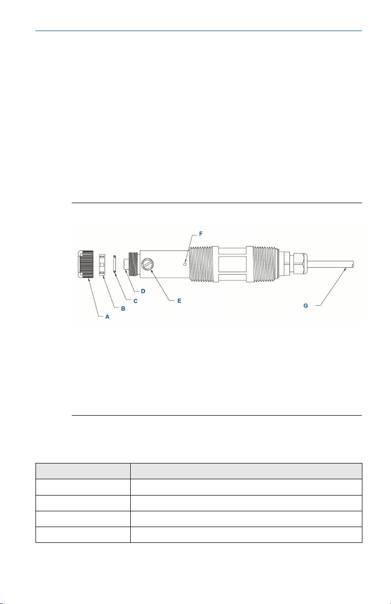
Figure 1-1: Rosemount 499ACL-03 Sensor Parts
A. Membrane retainer
B. Membrane assembly
C. O-ring
D. Cathode
E. Electrolyte fill plug (wrap with pipe tape)
F. Pressure equalizing port
G. Sensor cable (integral cable shown)
1.3
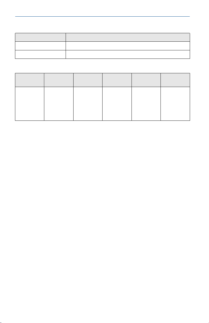
Table 1-1: Sensor Specifications
Physical characteristics Specifications
Pressure Sensor must drain to open atmosphere. No back pressure.
Temperature (operating) 32 to 122 °F (0 to 50 °C)
Process connection 1-in. male national pipe thread (MNPT)
Wetted parts Noryl®, Viton®, silicone, wood, and Zitex® (PTFE)
Quick Start Guide 3
Specifications
Page 4
Quick Start Guide November 2019
Table 1-1: Sensor Specifications (continued)
Physical characteristics Specifications
Cathode Gold mesh
Linearity 2% (typical)
Table 1-2: Other Specifications
Type PN Wetted
Low flow cell
with bubble
sweeping
(1)
nozzle
(1) Flow cell must drain to open atmosphere. Do not install the sensor in a pressurized line.
Temperature and pressure specifications for the low flow cell exceed the temperature and
pressure specifications for the sensor.
24091-01 Polycarbon-
materials
ate/
polyester,
316 stainless
steel, and
silicone
Process
connection
Compression
fitting for
¼-in. O.D.
tubing
Maximum
temperature
158 °F (70 °C) 90 psig
Maximum
pressure
(722 kPa abs)
4 Emerson.com/Rosemount
Page 5
November 2019 Quick Start Guide
2 Install
Install sensor in the low flow cell (PN 24091-01) only. Keep the flow as
constant as possible between 1 and 4 gph (3.8 to 15 L/hr). The flow cell must
drain to open atmosphere.
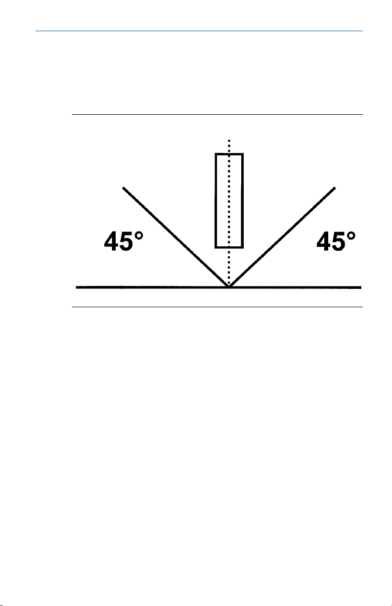
Figure 2-1: Sensor Orientation
Install sensor within 45 degrees of vertical.
Quick Start Guide 5
Page 6
Quick Start Guide November 2019
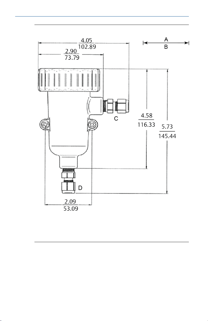
Figure 2-2: Low Flow Cell (PN 24091-00)
A. Inches
B. Millimeters
C. Outlet
D. Inlet
6 Emerson.com/Rosemount
Page 7

November 2019 Quick Start Guide
3 Wire
NOTICE
For additional wiring information on this product, including sensor
combinations not shown here, please refer to the Liquid Transmitter Wiring
Diagrams.
Figure 3-1: Rosemount 499ACL-03 Sensor Wiring to Rosemount 1056
and 56 Transmitters
Table 3-1: Rosemount 499ACL-03 Sensor Wiring to Rosemount 1056 and 56
Transmitters
Terminal
number
1 A White Resistance temperature
2 B White/red RTD sense
3 C Red RTD in
4 D Clear RTD shield
5 N/A N/A +5 V out
6 N/A N/A -4.5 V out
7 D Clear Anode shield
8 E Gray Anode
9 D Clear Cathode shield
Quick Start Guide 7
Letter Wire color Description
device (RTD) return
Page 8

Quick Start Guide November 2019
Table 3-1: Rosemount 499ACL-03 Sensor Wiring to Rosemount 1056 and 56
Transmitters (continued)
Terminal
number
10 F Orange Cathode
Letter Wire color Description
Figure 3-2: Rosemount 499ACL-03 Sensor Wiring to Rosemount 5081
Transmitter
Table 3-2: Rosemount 499ACL-03 Sensor Wiring to Rosemount 5081 Transmitter
Terminal
number
1 N/A N/A N/A
2 N/A N/A +0.8 V
3 A White RTD return
8 Emerson.com/Rosemount
Letter Wire color Description
Page 9

November 2019 Quick Start Guide
Table 3-2: Rosemount 499ACL-03 Sensor Wiring to Rosemount 5081 Transmitter
(continued)
Terminal
number
4 B White/red RTD sense
5 C Red RTD in
6 N/A N/A Reference guard
7 N/A N/A Reference in
8 D Clear Solution ground
9 N/A N/A pH guard
10 N/A N/A pH in
11 N/A N/A -5 V
12 N/A N/A +5 V
13 E Gray Anode
14 F Orange Cathode
15 N/A N/A HART®/FOUNDATION™ Fieldbus
16 N/A N/A HART/FOUNDATION Fieldbus (+)
Letter Wire color Description
(-)
Quick Start Guide 9
Page 10

Quick Start Guide November 2019
Figure 3-3: Rosemount 499ACL-03 Sensor Wiring to Rosemount 1066
Transmitter
Note
Connect clear shield wires to solution ground terminal on TB 2. Use wire nut
and pigtail if necessary.
Table 3-3: Rosemount 499ACL-03 Wiring to Rosemount 1066
Transmitter
Letter Color Terminal description
A Orange Cathode
B Gray Anode
C White Return
D White/red Sense
E Red RTD in
10 Emerson.com/Rosemount
Page 11

November 2019 Quick Start Guide
Figure 3-4: Rosemount 499ACL-03-01-54-VP Sensor Pin-out Diagram
(Top View of Connector End of Sensor)
Table 3-4: Pin-out Diagram
Terminal number Description
1 Cathode
2 N/A
3 RTD sense
4 Anode
5 RTD return
6 RTD in
When making a connection through a junction box (PN 23550-00), wire
point-to-point.
NOTICE
Use a wire nut and pigtail (included) when connecting several wires to the
same terminal.
Quick Start Guide 11
Page 12

Quick Start Guide November 2019
4 Calibrate
4.1 Zero point calibration
Even in the absence of monochloramine, the sensor generates a small signal
called the zero current. Failing to correct for the zero current can introduce a
bias, particularly if the monochloramine concentration is small (<0.4 ppm).
Zero the sensor when it is first placed in service and every time the fill
solution is changed.
To zero the sensor:
Procedure
1. Pour a cup of deionized or bottled water.
2. Place the sensor in the water.
3. Wait until the sensor current has reached a stable low value (at least
two hours).
4. Follow the transmitter prompts for zeroing the sensor.
Note
Refer to the manual for the transmitter you are using (Rosemount
56, 1056, or 1066).
The zero current should be between -10 and +15 nA. For more information,
refer to the transmitter manual.
4.2
12 Emerson.com/Rosemount
Full scale calibration
Because stable dilute monochloramine standards are not available, the
sensor must be calibrated against the results of a laboratory test run on a
grab sample of the process liquid.
Procedure
1. Place the sensor in the flow cell.
2. Start the sample and reagent flow.
3. Adjust the sample flow to between 1 and 4 gph.
4. Adjust the concentration so that it is near the upper end of the
operating range.
5. Wait for the readings to stabilize.
6. Follow the transmitter prompts to complete the calibration.
Note
Refer to the manual for the transmitter you are using (Rosemount
56, 1056, or 1066).
Page 13

November 2019 Quick Start Guide
Be sure taking the sample does not alter flow to the sensor.
7. After calibration, go to the Diagnostics menu and check the
sensitivity.
The sensitivity should be between 250 and 450 nA/ppm. For more
information, refer to the transmitter manual.
Quick Start Guide 13
Page 14

Quick Start Guide November 2019
5 Maintenance
WARNING
Pressurized spray injury
Before removing the sensor, be absolutely certain that the process pressure
is reduced to 0 psig and the process temperature is lowered to a safe level!
5.1 Cleaning the membrane
Keep the membrane clean and free from dirt and algae. Periodically inspect
the membrane. If it appears fouled, clean the membrane with water sprayed
from a wash bottle.
CAUTION
EQUIPMENT DAMAGE
Do not wipe the membrane with a tissue. Do not touch the membrane.
Doing so may damage the cathode, making the sensor unusable.
5.2 Replacing the electrolyte solution and membrane
WARNING
Corrosive substance
Fill solution is corrosive.
Avoid contact with skin and eyes.
Consult Material Safety Data Sheet (MSDS) for safety information.
Procedure
1. Unscrew the membrane retainer.
2. Remove the membrane assembly and O-ring.
See Figure 1-1.
3. Hold the sensor over a container with the cathode pointing down.
4. Remove the fill plug.
5. Allow the electrolyte solution to drain out.
6. Remove the old pipe tape from the plug.
7. Wrap the plug with one or two turns of pipe tape..
8. Prepare a new membrane.
14 Emerson.com/Rosemount
Page 15

November 2019 Quick Start Guide
a) Hold the membrane assembly with the cup formed by the
membrane and membrane holder pointing up.
b) Fill the cup with electrolyte solution.
9. Hold the sensor at about a 45 degree angle with the cathode end
pointing up.
10. Add electrolyte solution through the fill hole until the liquid
overflows.
11. Tap the sensor near the threads to release trapped air bubbles.
12. Add more electrolyte solution if necessary.
13. Place the fill plug in the electrolyte port and begin screwing it in.
14. After several threads have engaged, rotate the sensor so that the
cathode is pointing up and continue tightening the fill plug.
Do not overtighten.
15. Place a new O-ring in the groove around the cathode post.
16. Cover the cathode with electrolyte solution; then place the
membrane assembly over the cathode.
17. Screw the membrane retainer in place.
18. Hold the sensor with the cathode end pointing down.
19. Give the sensor several sharp shakes to dislodge air bubbles trapped
behind the cathode.
The sensor may require several hours operating at the polarizing
voltage to equilibrate after the electolyte solution has been replaced.
Quick Start Guide 15
Page 16

Quick Start Guide November 2019
6 Accessories
Part # Description
23750-00 Electrolyte fill plug with wooden osmotic pressure relief
9550094 O-ring, Viton 2-014
33521-00 Membrane retainer
23501-09 Monochloramine membrane assembly: includes one
23502-09 Monochloramine membrane kit: includes three
9210372 Monochloramine sensor fill solution, 4 oz (120 mL)
port
membrane assembly and one O-ring
membrane assemblies and three O-rings
16 Emerson.com/Rosemount
Page 17

November 2019 Quick Start Guide
Quick Start Guide 17
Page 18

Quick Start Guide November 2019
18 Emerson.com/Rosemount
Page 19

November 2019 Quick Start Guide
Quick Start Guide 19
Page 20

GLOBAL HEADQUARTERS
6021 Innovation Blvd.
Shakopee, MN 55379
+1 866 347 3427
+1 952 949 7001
liquid.csc@emerson.com
*00825-0300-3499*
Quick Start Guide
00825-0300-3499, Rev. AB
November 2019
NORTH AMERICA
Emerson Automation Solutions
8200 Market Blvd
Chanhassen, MN 55317
Toll Free +1 800 999 9307
F +1 952 949 7001
liquid.csc@emerson.com
MIDDLE EAST AND AFRICA
Emerson Automation Solutions
Emerson FZE
Jebel Ali Free Zone
Dubai, United Arab Emirates, P.O. Box
17033
+971 4 811 8100
+971 4 886 5465
liquid.csc@emerson.com
Linkedin.com/company/Emerson-
Automation-Solutions
twitter.com/rosemount_news
Facebook.com/Rosemount
youtube.com/RosemountMeasurement
EUROPE
Emerson Automation Solutions
Neuhofstrasse 19a PO Box 1046
CH-6340 Baar
Switzerland
+41 (0) 41 768 6111
+41 (0) 41 768 6300
liquid.csc@emerson.com
ASIA-PACIFIC
Emerson Automation Solutions
1 Pandan Crescent
Singapore 128461
Republic of Singapore
+65 6 777 8211
+65 6 777 0947
liquid.csc@emerson.com
©
2019 Emerson. All rights reserved.
The Emerson logo is a trademark and service
mark of Emerson Electric Co. Rosemount is a
mark of one of the Emerson family of companies.
All other marks are the property of their
respective owners.
 Loading...