

Page 1

Rosemount™ 499ACL-01
Free Chlorine Sensor
Quick Start Guide
00825-0100-3499, Rev AB
September 2019
Page 2

Quick Start Guide September 2019
Safety information
CAUTION
Sensor/process application compatibility
The wetted sensor materials may not be compatible with process composition and operating
conditions.
Application compatibility is entirely the operator's responsibility.
CAUTION
Equipment damage
Do not exceed pressure and temperature specifications
Pressure: 65 psig (549 kPa abs) max.
Temperature: 32 to 122 °F (0 to 50 °C)
WARNING
Physical access
Unauthorized personnel may potentially cause significant damage to and/or misconfiguration of end
users’ equipment. This could be intentional or unintentional and needs to be protected against.
Physical security is an important part of any security program and fundamental to protecting your
system. Restrict physical access by unauthorized personnel to protect end users’ assets. This is true for
all systems used within the facility.
Notice
ROSEMOUNT (“SELLER”) SHALL NOT BE LIABLE FOR TECHNICAL OR EDITORIAL ERRORS IN THIS
MANUAL OR OMISSIONS FROM THIS MANUAL. SELLER MAKES NO WARRANTIES, EXPRESSED OR
IMPLIED, INCLUDING THE IMPLIED WARRANTIES OF MERCHANTABILITY AND FITNESS FOR A
PARTICULAR PURPOSE, WITH RESPECT TO THIS MANUAL AND, IN NO EVENT, SHALL SELLER BE LIABLE
FOR ANY SPECIAL OR CONSEQUENTIAL DAMAGES INCLUDING, BUT NOT LIMITED TO, LOSS OF
PRODUCTION, LOSS OF PROFITS, ETC.
PRODUCT NAMES USED HEREIN ARE FOR MANUFACTURER OR SUPPLIER IDENTIFICATION ONLY AND
MAY BE TRADEMARKS/REGISTERED TRADEMARKS OF THESE COMPANIES.
THE CONTENTS OF THIS PUBLICATION ARE PRESENTED FOR INFORMATIONAL PURPOSES ONLY, AND
WHILE EVERY EFFORT HAS BEEN MADE TO ENSURE THEIR ACCURACY, THEY ARE NOT TO BE
CONSTRUED AS WARRANTIES OR GUARANTEES, EXPRESSED OR IMPLIED, REGARDING THE PRODUCTS
OR SERVICES DESCRIBED HEREIN OR THEIR USE OR APPLICABILITY. WE RESERVE THE RIGHT TO
MODIFY OR IMPROVE THE DESIGNS OR SPECIFICATIONS OF SUCH PRODUCTS AT ANY TIME.
SELLER DOES NOT ASSUME RESPONSIBILITY FOR THE SELECTION, USE, OR MAINTENANCE OF ANY
PRODUCT. RESPONSIBILITY FOR PROPER SELECTION, USE, AND MAINTENANCE OF ANY SELLER
PRODUCT REMAINS SOLELY WITH THE PURCHASER AND END-USER.
Warranty
1.
LIMITED WARRANTY: Subject to the limitations contained in Section 2 herein and except as
otherwise expressly provided herein, Rosemount (“Seller”) warrants that the firmware will
execute the programming instructions provided by Seller and that the Goods manufactured
or Services provided by Seller will be free from defects in materials or workmanship under
normal use and care until the expiration of the applicable warranty period. Goods are
warranted for twelve (12) months from the date of initial installation or eighteen (18) months
from the date of shipment by Seller, whichever period expires first. Consumables and
2 Emerson.com/Rosemount
Page 3

September 2019 Quick Start Guide
Services are warranted for a period of 90 days from the date of shipment or completion of the
Services. Products purchased by Seller from a third party for resale to Buyer (“Resale
Products”) shall carry only the warranty extended by the original manufacturer. Buyer agrees
that Seller has no liability for Resale Products beyond making a reasonable commercial effort
to arrange for procurement and shipping of the Resale Products. If Buyer discovers any
warranty defects and notifies Seller thereof in writing during the applicable warranty period,
Seller shall, at its option, promptly correct any errors that are found by Seller in the firmware
or Services, or repair or replace F.O.B. point of manufacture that portion of the Goods or
firmware found by Seller to be defective, or refund the purchase price of the defective
portion of the Goods/Services. All replacements or repairs necessitated by inadequate
maintenance, normal wear and usage, unsuitable power sources, unsuitable environmental
conditions, accident, misuse, improper installation, modification, repair, storage or handling,
or any other cause not the fault of Seller are not covered by this limited warranty, and shall be
at Buyer's expense. Seller shall not be obligated to pay any costs or charges incurred by Buyer
or any other party except as may be agreed upon in writing in advance by an authorized Seller
representative. All costs of dismantling, reinstallation and freight, and the time and expenses
of Seller's personnel for site travel and diagnosis under this warranty clause shall be borne by
Buyer unless accepted in writing by Seller. Goods repaired and parts replaced during the
warranty period shall be in warranty for the remainder of the original warranty period or
ninety (90) days, whichever is longer. This limited warranty is the only warranty made by
Seller and can be amended only in a writing signed by an authorized representative of Seller.
Except as otherwise expressly provided in the Agreement, THERE ARE NO REPRESENTATIONS
OR WARRANTIES OF ANY KIND, EXPRESSED OR IMPLIED, AS TO MERCHANTABILITY, FITNESS
FOR PARTICULAR PURPOSE, OR ANY OTHER MATTER WITH RESPECT TO ANY OF THE GOODS
OR SERVICES. It is understood that corrosion or erosion of materials is not covered by our
guarantee.
2.
LIMITATION OF REMEDY AND LIABILITY: SELLER SHALL NOT BE LIABLE FOR DAMAGES CAUSED
BY DELAY IN PERFORMANCE. THE SOLE AND EXCLUSIVE REMEDY FOR BREACH OF
WARRANTY HEREUNDER SHALL BE LIMITED TO REPAIR, CORRECTION, REPLACEMENT, OR
REFUND OF PURCHASE PRICE UNDER THE LIMITED WARRANTY CLAUSE IN SECTION 1
HEREIN. IN NO EVENT, REGARDLESS OF THE FORM OF THE CLAIM OR CAUSE OF ACTION
(WHETHER BASED IN CONTRACT, INFRINGEMENT, NEGLIGENCE, STRICT LIABILITY, OTHER
TORT, OR OTHERWISE), SHALL SELLER'S LIABILITY TO BUYER AND/OR ITS CUSTOMERS
EXCEED THE PRICE TO BUYER OF THE SPECIFIC GOODS MANUFACTURED OR SERVICES
PROVIDED BY SELLER GIVING RISE TO THE CLAIM OR CAUSE OF ACTION. BUYER AGREES
THAT IN NO EVENT SHALL SELLER'S LIABILITY TO BUYER AND/OR ITS CUSTOMERS EXTEND TO
INCLUDE INCIDENTAL, CONSEQUENTIAL OR PUNITIVE DAMAGES. THE TERM
“CONSEQUENTIAL DAMAGES” SHALL INCLUDE, BUT NOT BE LIMITED TO, LOSS OF
ANTICIPATED PROFITS, LOSS OF USE, LOSS OF REVENUE, AND COST OF CAPITAL.
Contents
First steps.....................................................................................................................................5
Install........................................................................................................................................... 8
Wire........................................................................................................................................... 12
Calibrate.................................................................................................................................... 17
Maintenance.............................................................................................................................. 19
Accessories................................................................................................................................ 22
Quick Start Guide 3
Page 4

Quick Start Guide September 2019
4 Emerson.com/Rosemount
Page 5

September 2019 Quick Start Guide
1 First steps
1.1 Unpack and inspect
Procedure
1. Inspect the shipping container. If it is damaged, contact the shipper
immediately for instructions.
2. If there is no apparent damage, unpack the container. Be sure all
items shown on the packing list are present. If items are missing,
notify Emerson immediately.
1.2 Product description
Figure 1-1: Rosemount 499ACL-01 Sensor Parts
A. Membrane retainer
B. Membrane assembly
C. O-ring
D. Cathode
E. Electrolyte fill plug (wrap with pipe tape)
F. Pressure equalizing port
G. Sensor cable (integral cable shown)
1.3
Table 1-1: Sensor Specifications
Physical characteristics Specifications
Range 0 to 10 ppm (mg/L) as Cl2. For higher ranges, consult the factory.
Pressure 0 to 65 psig (101 to 549 kPa abs)
Temperature (operating) 32 to 122 °F (0 to 50 °C)
Process connection 1-in. male national pipe thread (MNPT)
Quick Start Guide 5
Specifications
Page 6

Quick Start Guide September 2019
Table 1-1: Sensor Specifications (continued)
Physical characteristics Specifications
Wetted parts Noryl®, Viton®, platinum, polyethersulfone, polyester, wood, and
Accuracy Accuracy depends on the accuracy of the chemical test used to
pH range 6.0 to 9.5. For samples having pH between 9.5 and 10.0, consult
pH correction Use continuous pH correction (requires an auxiliary pH sensor) if
Linearity 2% (typical)
Sample conductivity > 50 µS/cm
Interferences Peroxides, permanganate, and chloramines
Response time 22 sec to 95% of final reading at 77 °F (25 °C)
Electrolyte volume 0.8 oz. (25 mL), approximately
Electrolyte life 3 months (approximately); for best results, replace electrolyte
Cable length See Ordering information table in the Product Data Sheet for cable
Sample flow Flow through: 2 to 5 gpm (3.8 to 19 L/min)
silicone
calibrate the sensor.
the factory. Samples with ranges below 6.0 require no pH
correction.
sample pH varies more than 0.2 pH (peak to peak). If pH variability
is less or seasonal, the pH sensor is generally not required.
monthly.
length options.
Open channel: 1 ft./sec (0.3 m/sec)
Low flow cell (PN 24091-00): 8 to 15 gph (30 to 57 L/hr)
Low flow cell (PN 24091-01): 2 to 5 gph (7.6 to 19 L/hr)
Weight/shipping weight 1 lb./3 lb. (0.5 kg/1.5 kg)
Table 1-2: Other Specifications
Type PN Wetted
materials
1½-in. tee 23567-00 CPVC and
Buna N
2-in. tee 915240-03 PVC and BunaN¾-in. NFPT 120 °F (49 °C) 60 psig (515
915240-04 1-in. NFPT
915240-05 1½-in. NFPT
6 Emerson.com/Rosemount
Process
connection
1½-in. socket 122 °F (50 °C) 65 psig (549
Maximum
temperature
Maximum
pressure
kPa abs)
kPa abs)
Page 7

September 2019 Quick Start Guide
Table 1-2: Other Specifications (continued)
Type PN Wetted
materials
Low flow
(1)
cell
24091-00 and
24091-01
Polycarbonate/
polyester,
316 stainless
Process
connection
Compression
fitting for
¼-in. O.D.
tubing
Maximum
temperature
Maximum
pressure
158 °F (70 °C) 90 psig
(722 kPa abs)
steel, and
silicone
(1) Temperature and pressure specifications for the low flow cell exceed the temperature and
pressure specifications for the sensor.
Quick Start Guide 7
Page 8

Quick Start Guide September 2019
2 Install
Install the sensor in a flowing sample. Keep the sample flow as constant as
possible at a value within the following limits:
Sample flow unit Flow limits
Flow through 1 to 5 gpm (3.8 to 19 L/min)
Open channel 1 ft/sec (0.3 m/sec)
Low flow cell (PN 24091-00) 8 to 15 gph (20 to 47 L/hr)
Low flow cell (PN 24091-01) 2 to 3 gph (120 to 190 mL/min)
Figure 2-1: Sensor Orientation
Install sensor within 45 degrees of vertical.
8 Emerson.com/Rosemount
Page 9

September 2019 Quick Start Guide
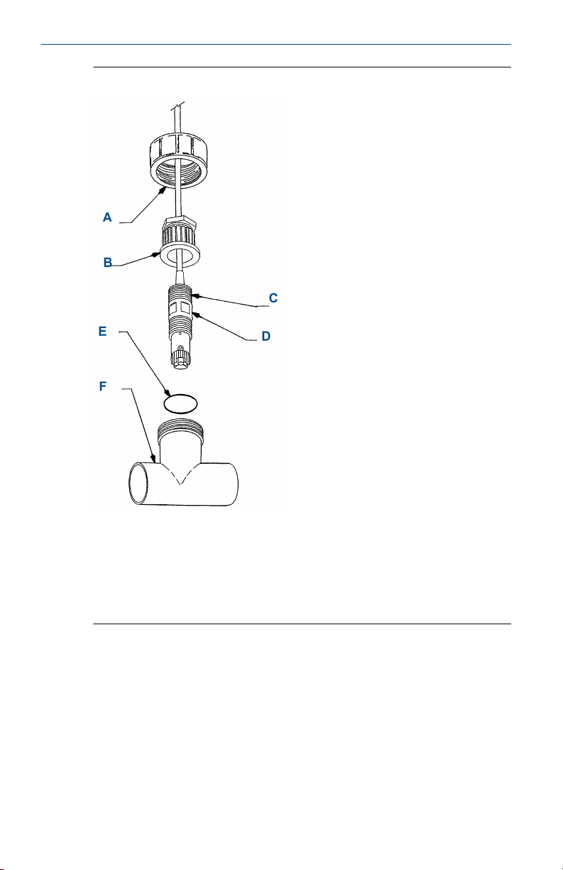
Figure 2-2: Flow Through 1½-in. Tee
A. Union coupler
B. 1-in. national pipe thread (NPT), two places
C. Sensor body: Rosemount 499A
D. 1-in. NPT flow cell adapter
E. O-ring 2-222
F. 1½-in. sched 80 CPVC tee body
Quick Start Guide 9
Page 10
Quick Start Guide September 2019
Figure 2-3: Flow Through 2-in. Tee
A. Union coupler
B. Adapter
C. 1-in. NPT (two places)
D. Sensor body: Rosemount 499A
E. O-ring 2-222
F. 2-in. sched 80 PVC tee body
10 Emerson.com/Rosemount
Page 11

September 2019 Quick Start Guide
Figure 2-4: Low Flow Cell (PN 24091-00)
A. Inches
B. Millimeters
C. Outlet
D. Inlet
Quick Start Guide 11
Page 12
Quick Start Guide September 2019
3 Wire
NOTICE
For additional wiring information on this product, including sensor
combinations not shown here, please refer to the Liquid Transmitter Wiring
Diagrams.
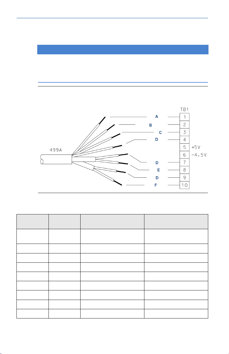
Figure 3-1: Rosemount 499ACL-01 Sensor Wiring to Rosemount 1056
and 56 Transmitters
Table 3-1: Rosemount 499ACL-01 Sensor Wiring to Rosemount 1056 and 56
Transmitters
Terminal
number
1 A White Resistance temperature
2 B White/red RTD sense
3 C Red RTD in
4 D Clear RTD shield
5 N/A N/A +5 V out
6 N/A N/A -4.5 V out
7 D Clear Anode shield
8 E Gray Anode
9 D Clear Cathode shield
12 Emerson.com/Rosemount
Letter Wire color Description
device (RTD) return
Page 13
September 2019 Quick Start Guide
Table 3-1: Rosemount 499ACL-01 Sensor Wiring to Rosemount 1056 and 56
Transmitters (continued)
Terminal
number
10 F Orange Cathode
Letter Wire color Description
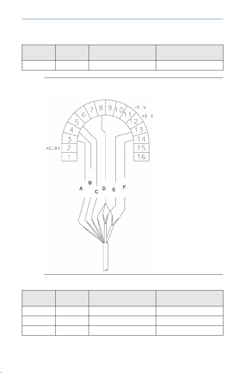
Figure 3-2: Rosemount 499ACL-01 Sensor Wiring to Rosemount 5081
Transmitter
Table 3-2: Rosemount 499ACL-01 Sensor Wiring to Rosemount 5081 Transmitter
Terminal
number
1 N/A N/A N/A
2 N/A N/A +0.8 V
3 A White RTD return
Quick Start Guide 13
Letter Wire color Description
Page 14

Quick Start Guide September 2019
Table 3-2: Rosemount 499ACL-01 Sensor Wiring to Rosemount 5081 Transmitter
(continued)
Terminal
number
4 B White/red RTD sense
5 C Red RTD in
6 N/A N/A Reference guard
7 N/A N/A Reference in
8 D Clear Solution ground
9 N/A N/A pH guard
10 N/A N/A pH in
11 N/A N/A -5 V
12 N/A N/A +5 V
13 E Gray Anode
14 F Orange Cathode
15 N/A N/A HART®/FOUNDATION™ Fieldbus
16 N/A N/A HART/FOUNDATION Fieldbus (+)
Letter Wire color Description
(-)
14 Emerson.com/Rosemount
Page 15

September 2019 Quick Start Guide
Figure 3-3: Rosemount 499ACL-01 Sensor Wiring to Rosemount 1066
Transmitter
Note
Connect clear shield wires to solution ground terminal on TB 2. Use wire nut
and pigtail if necessary.
A. Orange
B. Cathode
C. Anode
D. Gray
E. White
F. White/red
G. Red
H. Return
I. Sense
J. RTD in
Quick Start Guide 15
Page 16
Quick Start Guide September 2019
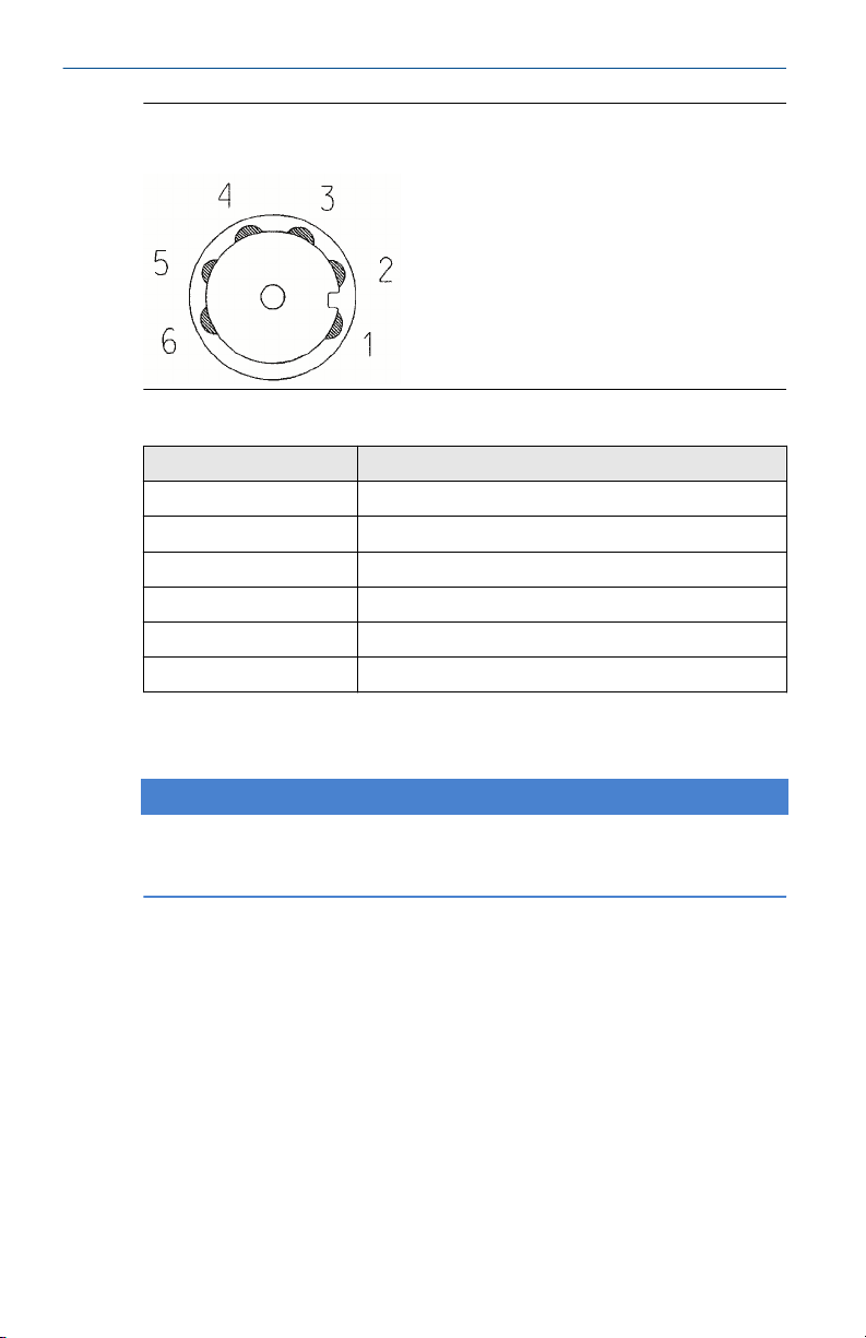
Figure 3-4: Rosemount 499ACL-01-01-54-VP Sensor Pin-out Diagram
(Top View of Connector End of Sensor)
Table 3-3: Pin-out Diagram
Terminal number Description
1 Cathode
2 N/A
3 RTD sense
4 Anode
5 RTD return
6 RTD in
When making a connection through a junction box (PN 23550-00), wire
point-to-point.
NOTICE
Use a wire nut and pigtail (included) when connecting several wires to the
same terminal.
16 Emerson.com/Rosemount
Page 17

September 2019 Quick Start Guide
4 Calibrate
4.1 Zero point calibration
Even in the absence of free chlorine, the sensor generates a small signal
called the zero current. Failing to correct for the zero current can introduce a
bias, particularly if the chlorine concentration is small (<0.4 ppm). Zero the
sensor when it is first placed in service and every time the fill solution is
changed.
To zero the sensor:
Procedure
1. Pour a cup of deionized or bottled water.
2. Add a few pinches of table salt to the water to increase the
conductivity.
3. Place the sensor in the water.
4. Wait until the sensor current has reached a stable low value (at least
two hours).
5. Follow the transmitter prompts for zeroing the sensor.
Note
Refer to the manual for the transmitter you are using (Rosemount
56, 1056, 5081, or 1066).
The zero current should be between -10 and +10 nA. For more information,
refer to the transmitter manual.
4.2
Quick Start Guide 17
Full scale calibration
Because stable dilute chlorine standards are not available, the sensor must
be calibrated against the results of a laboratory test run on a grab sample of
the process liquid.
Be sure taking the sample does not alter flow to the sensor and test the
sample immediately after taking it.
Procedure
1. Place the sensor in the flow cell.
2. Start the sample and reagent flow.
3. Adjust the sample flow to within the range given in the table in
Install.
4. Adjust the concentration so that it is near the upper end of the
operating range.
5. Wait for the readings to stabilize.
Page 18

Quick Start Guide September 2019
6. Follow the transmitter prompts to complete the calibration.
Note
Refer to the manual for the transmitter you are using (Rosemount
56, 1056, 5081, or 1066).
7. After calibration, go to the Diagnostics menu and check the
sensitivity.
The sensitivity should be between 300 and 700 nA/ppm. For more
information, refer to the transmitter manual.
18 Emerson.com/Rosemount
Page 19

September 2019 Quick Start Guide
5 Maintenance
Periodic maintenance and cleaning are required for best performance of the
sensor. Generally, the membrane and fill solution should be replaced every
one to three months. If the sensor is being used in water having conductivity
less than about 100 µS/cm, it might be necessary to replace the fill solution
(but not the membrane) more often. Sensors installed in harsh or dirty
environments require more frequent maintenance. The optimum
maintenance frequency is best determined by experience.
WARNING
Pressurized spray injury
Before removing the sensor, be absolutely certain that the process pressure
is reduced to 0 psig and the process temperature is lowered to a safe level!
5.1 Cleaning the membrane
Keep the membrane clean and free from dirt and algae. Clean the
membrane with water sprayed from a wash bottle. Do not use tissues to
clean the membrane.
5.2 Replacing the electrolyte solution and membrane
WARNING
Harmful substance
Fill solution may cause irritation. May be harmful if swallowed.
Read and follow the instructions.
Procedure
1. Unscrew the membrane retainer.
2. Remove the membrane assembly and O-ring.
See Figure 1-1.
3. Hold the sensor over a container with the cathode pointing down.
4. Remove the fill plug.
5. Allow the electrolyte solution to drain out.
6. Inspect the cathode.
a) If it is tarnished, clean it using a cotton-tipped swab dipped in
baking soda or alumina.
Quick Start Guide 19
Page 20

Quick Start Guide September 2019
Use type A dry powder alumina intended for metallographic
polishing of medium and soft metals.
b) Rinse thoroughly with water.
7. Remove the old pipe tape from the plug.
8. Wrap the plug with one or two turns of pipe tape..
9. Prepare a new membrane.
a) Hold the membrane assembly with the cup formed by the
membrane and membrane holder pointing up.
b) Fill the cup with electrolyte solution.
c) Wait for the wooden ring to soak up the solution.
This usually takes several minutes.
10. Hold the sensor at about a 45 degree angle with the cathode end
pointing up.
11. Add electrolyte solution through the fill hole until the liquid
overflows.
12. Tap the sensor near the threads to release trapped air bubbles.
13. Add more electrolyte solution if necessary.
14. Place the fill plug in the electrolyte port and begin screwing it in.
15. After several threads have engaged, rotate the sensor so that the
cathode is pointing up and continue tightening the fill plug.
Do not overtighten.
16. Place a new O-ring in the groove around the cathode post.
17. Cover the holes at the base of the cathode stem with several drops of
electrolyte solution.
18. Insert a small blunt probe, like a toothpick with the end cut off,
through the pressure equalizing port.
See Figure 1-1.
CAUTION
Equipment damage
A sharp probe may puncture the bladder and destroy the sensor.
Do not use a sharp probe.
19. Gently press the probe against the bladder several times to force
liquid through the holes at the base of the cathode stem. Keep
20 Emerson.com/Rosemount
Page 21

September 2019 Quick Start Guide
pressing the bladder until no air bubbles can be seen leaving the
holes.
Be sure the holes remain covered with electrolyte solution.
20. Place a drop of electrolyte solution on the cathode; then place the
membrane assembly over the cathode.
21. Screw the membrane retainer in place.
The sensor may require several hours operating at the polarizing
voltage to equilibrate after the electrolyte solution has been
replenished.
Quick Start Guide 21
Page 22

Quick Start Guide September 2019
6 Accessories
Part # Description
33523-00 Electrolyte fill plug
9550094 O-ring, Viton 2-014
33521-00 Membrane retainer
23501-08 Free chlorine membrane assembly: includes one
23502-08 Free chlorine membrane kit: includes three membrane
9210356 #4 free chlorine sensor fill solution, 4 oz (120 mL)
membrane assembly and one O-ring
assemblies and three O-rings
22 Emerson.com/Rosemount
Page 23

September 2019 Quick Start Guide
Quick Start Guide 23
Page 24

*00825-0100-3499*
00825-0100-3499, Rev. AB
Quick Start Guide
September 2019
GLOBAL HEADQUARTERS
Emerson Automation Solutions
6021 Innovation Blvd
Shakopee, MN 55379, USA
+1 800 999 9307 or +1 952 906 8888
F +1 952 949 7001
liquid.csc@emerson.com
EUROPE
Emerson Automation Solutions
Neuhofstrasse 19a P.O. Box 1046
CH-6340 Baar
Switzerland
T + 41 (0) 41 768 6111
F + 41 (0) 41 768 6300
liquid.csc@emerson.com
Linkedin.com/company/Emerson-
Automation-Solutions
twitter.com/rosemount_news
Facebook.com/Rosemount
youtube.com/RosemountMeasurement
NORTH AMERICA
Emerson Automation Solutions
8200 Market Blvd
Chanhassen, MN 55317
Toll Free +1 800 999 9307
F +1 952 949 7001
liquid.csc@emerson.com
MIDDLE EAST AND AFRICA
Emerson Automation Solutions
Emerson FZE
Jebel Ali Free Zone
Dubai, United Arab Emirates, P.O. Box
17033
T +971 4 811 8100
F +971 4 886 5465
liquid.csc@emerson.com
©
2019 Emerson. All rights reserved.
The Emerson logo is a trademark and service
mark of Emerson Electric Co. Rosemount is a
mark of one of the Emerson family of companies.
All other marks are the property of their
respective owners.
 Loading...