

Page 1

Reference Manual
00809-0100-4191, Rev BA
August 2001
Model 470 Transient Protector
www.rosemount.com
Page 2

Page 3

Reference Manual
00809-0100-4191, Rev BA
August 2001
Model 470
Model 470 Transient Protector
NOTICE
Read this manual before working with the product. For personal and system safety, and for
optimum product perf ormance, make sure you thoroughly understand the contents bef ore
installing, using, or maintaining this product.
Within the United States, Rosemount Inc. has two toll-free assist ance numbers:
Customer Central
Technical support, quoting, and order-related questions.
1-800-999-9307 (7:00 am to 7:00 pm CST)
North American Response Center
Equipment servic e needs.
1-800-654-7768 (24 hours—includes Canada)
Outside of the Un ited States, contact your local Rosemount representative.
The products described in this document are NOT designed for nuclear-qualified
applications . Using non-nuclear qualified products in applications that require
nuclear-qualif i ed hardware or products may cause inaccurate readings.
For information on Rosemount nuclear-qualified products, contact your local Ro se mount
Sales Representative.
www.rosemount.com
Page 4

Page 5

Reference Manual
00809-0100-4191, Rev BA
8/16/01
Model 470
Table of Contents
SECTION 1 Introduction
SECTION 2 Installation
SECTION 3 Operation
SECTION 4 Hardware and Software Maintenance and Troubleshooting
APPENDIX A Reference Data
Overview of Manual. . . . . . . . . . . . . . . . . . . . . . . . . . . . . . . . . . . . . . . 1-1
Installation Procedure . . . . . . . . . . . . . . . . . . . . . . . . . . . . . . . . . . . . . 2-2
Cathodic Protection. . . . . . . . . . . . . . . . . . . . . . . . . . . . . . . . . . . . . . . 2-3
Operation. . . . . . . . . . . . . . . . . . . . . . . . . . . . . . . . . . . . . . . . . . . . . . . 3-1
Return of Material . . . . . . . . . . . . . . . . . . . . . . . . . . . . . . . . . . . . . . . . 4-1
470D and 470C Transient Protector . . . . . . . . . . . . . . . . . . . . . . . . . .A-1
470L and 470J Transient Protector . . . . . . . . . . . . . . . . . . . . . . . . . . .A-2
Hazardous Locations Certifications . . . . . . . . . . . . . . . . . . . . . . . . . . .A-2
Dimensional Drawing. . . . . . . . . . . . . . . . . . . . . . . . . . . . . . . . . . . . . .A-3
Ordering Information . . . . . . . . . . . . . . . . . . . . . . . . . . . . . . . . . . . . .A-3
www.rosemount.com
Page 6

Model 470
Reference Manual
00809-0100-4191, Rev BA
8/16/01
TOC-2
Page 7

Reference Manual
00809-0100-4191, Rev BA
August 2001
Section 1 Introduction
Model 470
OVERVIEW OF MANUAL The Rosemount
transients induced by light ning, welding, heavy el ectrical equipment , or switch
gears. The Model 470 continues to protect transmitters even after repeated
strikes of up to 5,000 amps. In laboratory simulated lightning tests, t he Mod el
470 withstood 2,000 amps or 10,000 volts without damage to either the
transient protector or the transmitter.
Models 470D and 470C are designed to protect two-wi re trans mitter s that are
capable of withstanding 120 volts from lead to case, and can also be used to
protect the receiver or RTU. Models 470L and 470J are designed to protect
low power or other three-wire transmitters.
The weatherproof, st ainless steel-cased protector functions under sever e
environmental condit ions including high temperature and humidity.
®
Model 470 Transient Protector prevents s damage from
www.rosemount.com
Page 8

Page 9

Reference Manual
00809-0100-4191, Rev BA
August 2001
Section 2 Installation
Installation Procedure . . . . . . . . . . . . . . . . . . . . . . . . . . . . page 2-2
Cathodic Protection . . . . . . . . . . . . . . . . . . . . . . . . . . . . . .page 2-3
The circuitry of the Model 470 T ransient Pr otector is potted in a
steep pipe nipple. The protector can be installed in a 100% humidity, -40 to
212°F (-40 to 100°C) environment. A bypass wire and two clamps are
provided to electrically bond the case of the protector to the case of the
instrument being protect ed.
Figure 2-1 and 2-2 show the wiring diagram of a typical installation consisting
of a two-wire transmitter, a power supply, a receiver, and two transient
protectors. Figure 2-3 and 2-4 show the wiring diagram for a typical
installation with a three-wire transmitter.
The following installation considerations should be deliberated before
proceeding:
• The bypass wire ensures a low resistance path between the protector
case and the transmitter case.
• The transmitter case is to be well-grounded to provide a
low-impedance path to gr ound (unless cathodic protection is used).
• To provide protection for receiving equipment, install an additional
protector at a point where field wiring enters the building. The amount
of protection provided by a protector located at this point is critically
dependent upon the adequacy of the ground connection.
• If the power supply (45 V dc maximum) is capable of delivering more
than 0.5 amps short circu it current, use a limiting resistor (47 ohms
minimum,
conduction by the protector after a transient occurs.
1
/2 watt, carbon composition) to prevent continuous
Model 470
1
/2 in. stainl ess
www.rosemount.com
Page 10

Model 470
Reference Manual
00809-0100-4191, Rev BA
August 2001
INSTALLATION PROCEDURE
Step 1:
Locate the end of the protector marke d “transmitter lead s,” and scr ew this end
of the protector into the conduit connection of the transmitter housing. Attach
the lead wires as shown in Figure 2-1, 2-2, 2-3, and 2-4.
Step 2:
At the “field leads” end of the pro tector, connect the lead wires as shown in
Figure 2-1, 2-2, 2-3, and 2-4.
Step 3:
Locate a point on the transmitter housi ng to connect the bypass wire.
Thoroughly clean all dirt , gr ease, paint, or other coatings from the surface of
the protector and from the point of connection on the transmitter housing.
Using stainless steel clamps, attach the bypass wire firmly. Keep the bypass
wire as short and straight as possi ble. This lead must be connected even in
installations that use a separate case connection lead (green lead). The
bypass wire is clad with nickel and sealed at both ends for corrosion
protection, theref ore do not cut excess wire. Avoid connections to aluminum,
as galvanic corrosion may result.
Step 4:
Important: The protector case as well as all equipment attached to the
protector must be electrically grounded and bonded in strict accordance with
articles 250 and 280 of the National Electrical Code
(ANSI C2-1977) and the Lightning Protecti on Code (NFPA 78-1968; ANSI
C5.1-1969) and Section 9 of the National Electric Safety Code (ANSI
C2-1984).
Step 5:
When a transient prot ector is used t o pr otect r eceivi ng equipment locat ed in a
control room, bond the protector to a well-established earth ground.
Step 6:
In a typical two-wire transmitter installation, the loop resistance added by the
Model 470C or 470D (20 ohms per loop) should have no effect on operation.
In a three-wire system, however, the volt age signal measured by the receiver
is affected by the volt age drop across the common (brown) lead. the
resistance add ed by the Model 470L or 470J (1 ohm maximum per l ead) may
have a measurable effect on measured out put. In this instance, the
transmitter should be recali brated with the protector connected.
2-2
Page 11

Reference Manual
00809-0100-4191, Rev BA
August 2001
Model 470
CATHODIC PROTECTION
If cathodic protection is used, the transmit ter case and protector case are
deliberately kept negative with respect to earth ground. Direct grounding of
the case or associated piping per t he electrical codes would defeat cathodic
protection. In this case , the electrical transient current should be diverted to
ground across the cathodic protection power supply with a suitable lightning
arrestor. The green case grounding lead on Models 470C or 470J can not be
connected without defeating cathodic protection.
Figure 2-1. Installati on Schematic for Two-wire Tr ansmitter and Control Room Equipment
Using Two Model 470D Transient Protectors
Field
Leads
(+) Red
(–) Black
Case
Model
470D
Bypass Wire
Case
dc
Power
Supply
+
–
Earth
Ground
Control Room Wall
47 Ohms
Signal
Loop
Ground
(optional)
Receiver
Protected
Case
Earth
Ground
Yellow
Black
Case
Model
470D
Red
Black
Earth
Ground
Figure 2-2. Installati on Schematic for Two-wire Tr ansmitter and Control Room Equipment
Using Two Model 470C Transient Protectors
Field
Leads
(+) Red
(–) Black
(+) Green
Case
Model
470C
Bypass Wire
Case
dc
Power
Supply
+
–
Earth
Ground
Control Room Wall
47 Ohms
Signal
Loop
Ground
(optional)
Receiver
Protected
Case
Yellow
Black
Green
Earth
Ground
Case
Model
470C
Red
Black
Green
Earth
Ground
Protected
Transmitter Case
Two-wire
Yellow
Black
Transmitter Case
Yellow
Black
Green
+
Earth
Ground
Protected
Two-wire
+
–
Earth
Ground
–
470-0237A
470-0238A
2-3
Page 12
Model 470
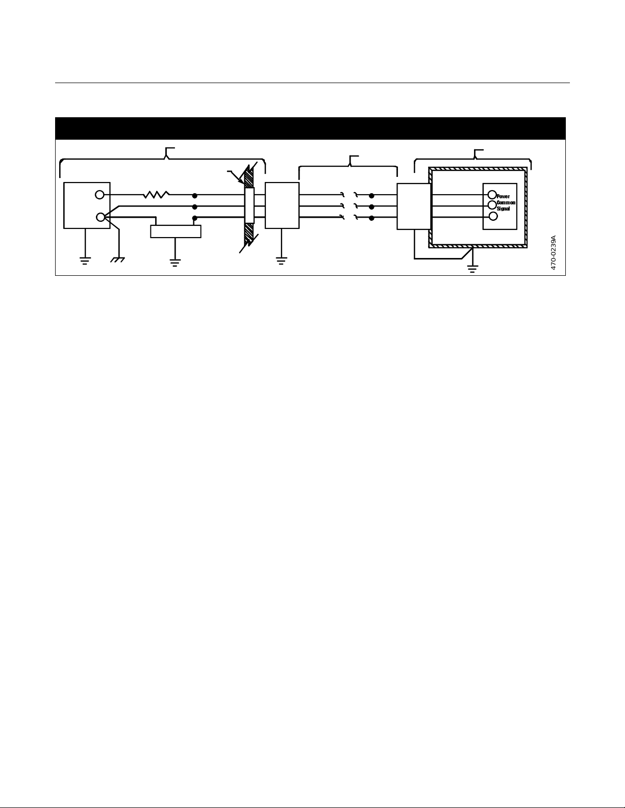
Figure 2-3. Installation Schematic for Three-wire Transmitter and Control Room Equipment
Using Two Model 470L Transient Protectors
Field
Leads
Case
(+) Red
(–) Black
(+) Brown Brown
Model
470L
Bypass Wire
Case
dc
Power
Supply
+
–
Earth
Ground
Control Room Wall
47 Ohms
Signal
Loop
Ground
(optional)
Receiver
Protected
Case
Earth
Ground
Yellow
Black
Brown
Case
Model
470L
Red
Black
Brown
Earth
Ground
Reference Manual
00809-0100-4191, Rev BA
August 2001
Protected
Transmitte r C a se
Yellow
Black
Three-wire
+
3RZHU
&RPPRQ
–
6LJQDO
+
Earth
Ground
470-0239A
2-4
Page 13

Reference Manual
00809-0100-4191, Rev BA
August 2001
Section 3 Operation
The Model 470 Transient Protector is designed to prot ect two- and three-wire
current transmitters or similar dc equipment from damage due to high energy
transients induced into field wiring by nearby lightning strikes or by trans ients
in adjacent wiring. It can be used to protect any current or voltage signal
equipment, subject to the follo wing requirements:
• The dc voltage between leadwires and from either leadwires and from
either leadwire to ground should not exc eed 45 V dc nominal (48 V dc
maximum).
• The protected equipment can withstand 120 volts peak with respect to
ground.
This protector is intended to protect only the instrument being bypassed, and is not a safety
device. To prevent damage or injur y t o other equip ment or to pers on nel in event of a nearb y
lightning st ri ke, the equipment to which the protector is bypassed must be w el l -grounded in
accordance with the National Electrical Code (ANSI C2-1977), the Lightning Protection
Code (NFPA 78-1968; ANSI C5.1-1 969 ), and S ectio n 9 of the N ati onal El ectr ic Saf et y Code
(ANSI C2-1984).
Model 470
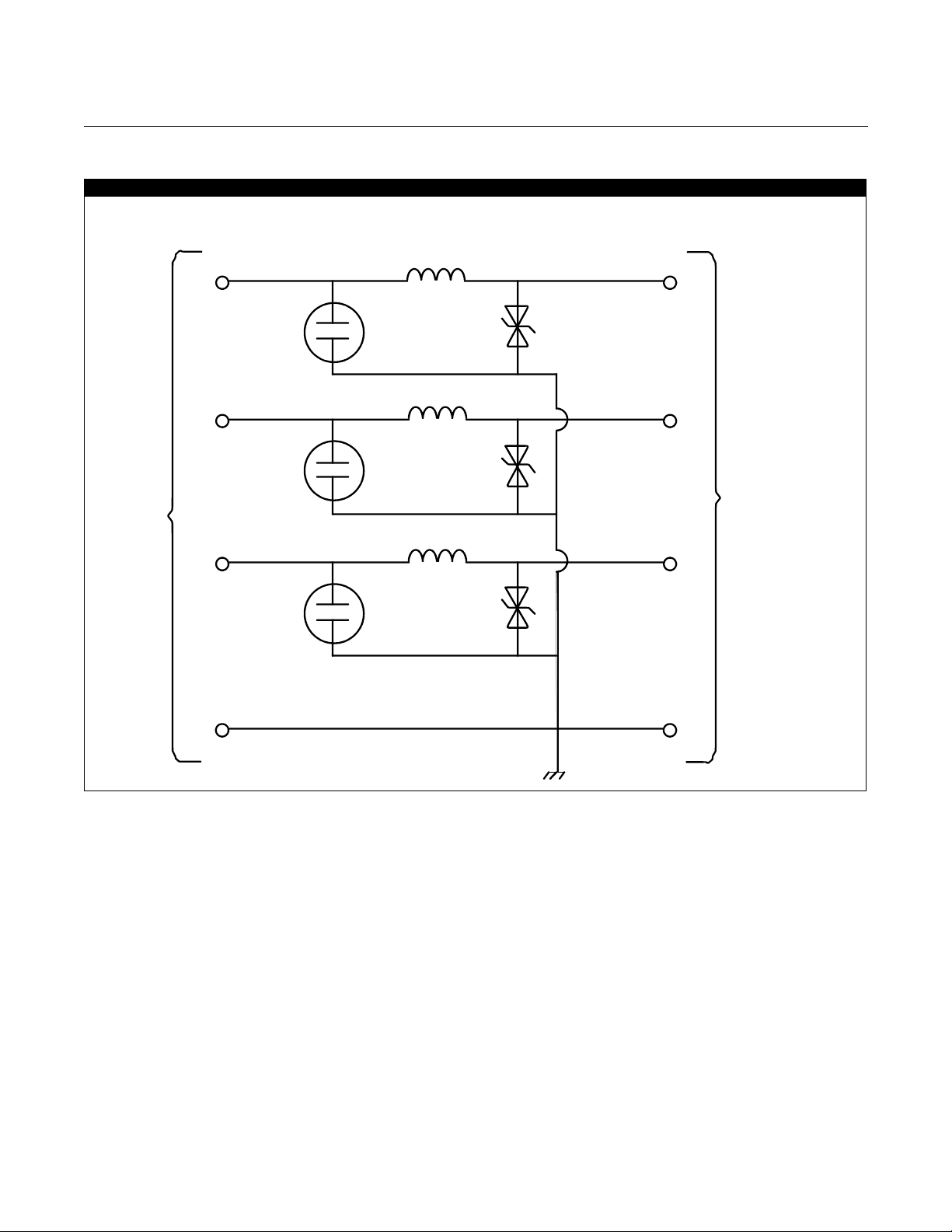
The protector circuits are shown in Figure3-1.
OPERATION The Rosemount Model 470 Transient Protector consists of separate circuits—
one for each lead wire (excluding the green ground wire ) epoxy-seal ed insid e
1
a
/2–14 NPT stainless steel pipe nipple for direct mounting to a transmitter.
Each signal lead uses an identical protector circuit consisting of a gas-filled
spark gap, an inductor, and a fast-response bipolar zener diode.
A high-voltage transient appearin g on any f ield si gnal wir e is condu cted to the
case through the gas-filled spark gap. This device conducts large currents,
but has a slow reaction time. The fast-r isi ng portion of the transient is
conducted to the case through the zen er diode, which has a fast reaction
time. The inductor limits the diode current during the time required for the
spark gap to conduct.
The bypass w ire connected between the protector case and instrument case
ensures that both remain at the same potent ial, thus preventing dielectric
breakdown inside the protected device.
Once the spark gap has begun to conduct, it will continue to do so unless the
instrument power supply limits current to 0.5 amps or less. A 47-ohm
quenching resist or can be added t o preven t c onducti on after the t ransie nt has
discharged.
The green lead used in the Model 470C or 470J is connected directly to the
protector case, and is used only in those instan ces where a separate
instrument case ground is des ir ed. It cannot be used to replace the bypass
wire, and cannot be used in cathodically protected installations.
www.rosemount.com
Page 14
Model 470
Figure 3-1. Schematic Diagram
Red
Reference Manual
00809-0100-4191, Rev BA
August 2001
Inductor
Yellow
Field leads
Black
Brown (470L or 470J only)
Green (470C or 470J only)
Black
Brown (470L or 470J only)
Green (470C or 470J on ly)
Protector Case
To end device
transmitter
470-0242A
3-2
Page 15

Reference Manual
00809-0100-4191, Rev BA
August 2001
Section 4 Hardware and Software
Maintenance and
Troubleshooting
The transient protector is non- repairable. Maintenance is limited to a periodic
inspection of the condition of t he grounding and bypass wiring.
An ohmmeter which will not provide more than 45 volts across the measuring
terminals is required to deter mine if a protector is operational. Disconnect all
leadwires and measure the following resistance:
1. Red to Yellow - 10 ohms or less
2. Black to Black - 10 ohms or less
3. Brown to Brown - 10 ohms or less
4. Green to Green - 1 ohms or less
5. Any signal leadwire to case - greater tha n 1 megohm
6. Green lead to case - 1 ohm or less
Model 470
Failure to obtain these readings is justification to replace the protector.
RETURN OF MATERIAL To expedite the return process, call the Rosemount North American
Response Center at 800-654-RSMT (7768) toll-free number.
This center, available 24 hours a day, will assist you with any needed
information or materials.
The center will ask for product model and serial numbers, and will provide a
Return Material Authoriz ati on (RMA) number. The center will also ask for the
name of the process material to which the product was last exposed.
CAUTION
People who handle products exposed to a hazardous substance can avoid
injury if they are infor m ed and understand the hazard. If the product being
returned was expos ed t o a haz ardou s s ubsta nce as de fined by OSHA, a copy
of the required Material Safety Dat a Sheet (MSDS) for each hazardous
substance identified must be included with the returned goods.
The Rosemount North American Response Center will detail the additional
information and procedu res necessar y to re turn goods expos ed to hazardous
substances.
www.rosemount.com
Page 16

Page 17

Reference Manual
00809-0100-4191, Rev BA
August 2001
Appendix A Reference Data
470D and 470C Transient Protector . . . . . . . . . . . . . . . . .page A-1
470L and 470J Tr ansient Protector . . . . . . . . . . . . . . . . . .page A-2
Hazardous Locations Certificat ions . . . . . . . . . . . . . . . . .page A-2
Dimensiona l Drawing . . . . . . . . . . . . . . . . . . . . . . . . . . . . .page A-3
Ordering Information . . . . . . . . . . . . . . . . . . . . . . . . . . . . . page A-3
Temperature Limits
–40 to 212 °F (–40 to 100 °C)
Humidity Limits
0 to 100% relative humidity
Model 470
470D AND 470C TRANSIENT PROTECTOR
Maximum Clamping V oltage
Any lead to case
dc
68 V
100 kV/microsecond surge
70 V peak
1,000 kV/microsecond surge
120 V peak
Tr ansient Surge Current
Up to 5,000 amps for 20 microseconds—repeated strikes
Transmitter Output Compatibility
4–20 mA
Transmitter Power Supply
45 V dc maximum
Loop Resistance Added by Protector
20 ohms maximum
(1)
(1)
(1)
www.rosemount.com
(1) Tested under reference operating conditions.
Page 18

Model 470
Reference Manual
00809-0100-4191, Rev BA
August 2001
470L AND 470J TRANSIENT PROTECTOR
HAZARDOUS LOCATIONS CERTIFICATIONS
Transmitter Output Compatibility
4–20 mA (regular power)
0.8 to 3.2 V (low power)
1.0 to 5.0 V (low power)
Transmitter Power Supply
45 V dc maximum, 5 V dc minimum
Loop Resistance Added
by Protector
(1)
1 ohm per lead maximum
Canadian Standards Association (CSA) Approvals
E6 Explosion proof for Class I, Division 1, Groups C and D; Dust-Ignition
Proof Class II, Division 1, Group s E, F, and G; Dust-Igni tion Proof Class
III, Division 1 hazardous locat ions;
Suitable for Class I Division 2 Groups A, B, C, and D. CSA Enclosure
Type 4. Factory Sealed.
I6 Intrinsic Safety for Class I, Division 1, Groups A, B, C, and D. Intrinsic
safety approval only when used with the barrier parameter in Table A-1.
CSA Enclosure 4.
Centro Elettrotecnico Speriment ale Italiano (CESI/CENELEC)
Certification
C8 Flameproof Approval:
EEx d IIC T6
Intrinsic Safety Approval:
EEx ia IIC T6
= 45 V
U
max
Ceq = 1 nF
= 1 mH
L
eq
A-2
Table A-1. CSA Entity Approvals
Barrier Manufacturer/Model
Any CSA approved zener barrier
≤ 30 V, ≥ 330 ⍀ or
≤ 28 V, ≥ 300 ⍀ or
≤ 22 V, ≥ 180 ⍀
Foxboro Converters
2AI-I2V-CGB, 2AI-I3V-CGB
2AS-I3I-CGB, 2AS-I2I-CGB
3AD-I3IA-CS-E / CGB-A
3A2-I2D-CS-E / CGB-A
3A2-I3D-CS-E / CGB-A
3A4-I2DA- C S- E / CGB-A
3F4-I2DA1-CS-E / CGB-A
(1) Tested under reference operating conditions.
CSA Approved for C lass 1, Division 1,
Groups
A B C D
••••
NA • • •
Page 19

Reference Manual
00809-0100-4191, Rev BA
August 2001
DIMENSIONAL DRAWING
Dimensional Drawing
31/2-Inch (Models 470D and 470C) or
5-Inch (Models 470L and 470J) Nipple,
1
/2–14 NPT Stainless Steel
Model 470
Field Leads
16 Gauge Leads
Transmitter Leads
18-Inch
Minimum
Lead Wires
470-0241A
ORDERING
INFORMATION
Model Product Description Nipple Length
470D Transient Protector 3½-inch
470C Transient Protector (CSA Approved Unit) 3½-inch
470L Transient Protector – Low Power 5-inch
470J Transient Protector – Low Power (CSA Approved Unit) 5-inch
Code Loop Resistance Maximum Supply Voltage
1 20 Ohms (Models 470D, 470C) 45 V
1 1 Ohm per Lead, Max. (Models 470L, 470J) 45 V
Code Options
NA No Approval Requi red
E6 Canadian Standards Associati on (C SA) Explosion-Proof Approval (Models 470C, 470J only)
I6 Canadian Standards Association (CSA) Intrinsic Safety Approval (Models 470C, 470J only)
C8 Centro Elett rot ecnic o Speri me ntal e It al ian o (CESI /CEN ELEC ) Flamep roof and Intrins ic Saf et y Cert ifi catio ns (Mode ls 470D , 470L on ly)
Typical Model Number: 470D 1 NA
A-3
Page 20

Page 21

Page 22

Reference Manual
00809-0100-4191, Rev BA
August 2001
Model 470
Rosemount and the Rosemount logotype are registe red trademarks of Rosemount Inc.
PlantWeb is a mark of one of the Emerson Process Management companies.
All other marks are the property of their respective owners.
Cover Photo: 470-470-002ab.tif
Emerson Process Management
Rosemount Inc.
8200 Market Boul evard
Chanhassen, MN 553 17 U SA
T 1-800-999-9307
F (952) 949-7001
www.rosemount.com
¢00809-0100-419 1y¤
© 8/16/01 Rosemount I nc . All rights reserved.
 Loading...