

Page 1
Product Data Sheet
October 2017
00813-0100-4022, Rev LA
Rosemount™ 4600 Oil & Gas Panel Pressure
Transmitter
A compact, lightweight, all-welded stainless steel design
Up to 40:1 rangeability for increased flexibility and reduced inventories
3-year stability guarantee reduces maintenance costs
Leading edge capacitance sensor with integral temperature measurement for improved
total performance
4–20 mA HART
®
Smart capabilities and 0.25% of calibrated span reference accuracy
Page 2
Rosemount 4600
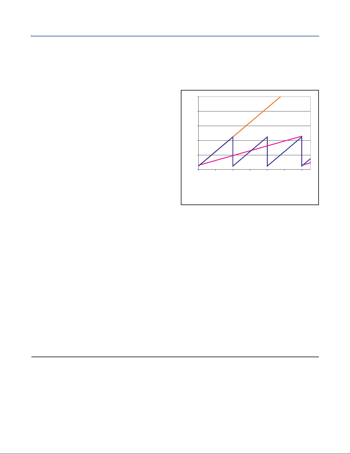
Operating Conditions:
Calibration Span: 3,000 psi
Ambient Temperature Change: ±50 °F (±28 °C)
Required Measurement Performance: 1.1% of Span
CALIBRATION FREQUENCY
1.75%
1.50%
1.25%
1.00%
0.75%
0
6
12
18
24
30
36
0.50%
Percent of Span Error
Months in Service
R
o
se
m
o
u
n
t
4
6
0
0
C
o
m
p
e
t
i
t
i
v
e
U
n
i
t
C
o
m
p
e
t
i
t
i
v
e
U
n
i
t
w
i
t
h
o
u
t
C
a
l
i
b
ra
t
i
o
n
October 2017
Legendary Rosemount Performance, Customized for your Panel Applications
The Rosemount 4600 Oil & Gas Panel Pressure Transmitter is a
compact, reliable transmitter designed to meet your
panel-mount monitoring needs. The transmitter continues the
™
Emerson
tradition of delivering superior performance, industry
leading reliability, and exceptional value.
A compact, lightweight, all-welded stainless
steel design
You asked for it and we’ve delivered — the stability, performance
and reliability of Rosemount products are now available in a
compact transmitter for your space and weight constrained
panel applications. The entire transmitter weighs less than
2.1 lb. (0.95 kg) and the all-welded, hermetic enclosure
maximizes reliability by minimizing environmental effects, such
as salt spray and humidity, on the electronics and sensor.
Up to 40:1 rangeability for increased flexibility
and reduced inventories
Emerson understands that oil and gas well pressures are
sometimes unpredictable, and that’s why we’ve incorporated
40:1 rangeability into the Rosemount 4600. Not only does 40:1
rangeability allow you incredible flexibility, it also lowers your
transmitter inventories by allowing you to measure pressure
ranges from 20 psi to 20,000 psi with only four transmitter
ranges.
3-year stability guarantee reduces maintenance
costs
Most competitive devices can drift out of specification after just
a few months and require recalibration, which consumes both
your time and money. The Rosemount 4600 carries a 3-year “Set
and Forget” stability guarantee to reduce the frequency of
calibration and lower maintenance costs.
Leading edge capacitance sensor with integral
temperature measurement for improved total
performance
Integral temperature measurement means the Rosemount 4600
provides superior temperature compensation and therefore, a
more precise pressure measurement over the entire operating
temperature range.
Contents
Legendary Rosemount Performance, Customized for
your Panel Applications . . . . . . . . . . . . . . . . . . . . . . . . . . . . 2
Ordering Information . . . . . . . . . . . . . . . . . . . . . . . . . . . . . 3
2
4-20 mA HART Smart capabilities and 0.25% of
calibrated span reference accuracy
The HART protocol enables quick and easy reranging, calibration
and troubleshooting for nearly effortless field adjustments. As
always, reference accuracy is specified as a percent of calibrated
span, not as a percent of full scale, so you’re guaranteed 0.25%
reference accuracy whether you’re measuring 20,000 psi or
20 psi.
Specifications . . . . . . . . . . . . . . . . . . . . . . . . . . . . . . . . . . . . 5
Product Certifications . . . . . . . . . . . . . . . . . . . . . . . . . . . . .8
Dimensional Drawings . . . . . . . . . . . . . . . . . . . . . . . . . . . .11
Emerson.com/Rosemount
Page 3
October 2017
Rosemount 4600
Ordering Information
Specification and selection of product materials, options, or components must be made by the purchaser of the equipment. See
page 7 for more information on Material Selection.
Table 1. Rosemount 4600 Oil & Gas Pressure Transmitter Ordering Information
The starred offerings (★) represent the most common options and should be selected for best delivery. The non-starred offerings are subject
to additional delivery lead time.
Model Transmitter type
4600 Oil and gas panel pressure transmitter
Measurement type
GSealed gauge
A Absolute
Pressure range
2 0-20 to 0-150 psi
4 0-125 to 0-5000 psi
5 0-330 to 0-10,000 psi
6 0-660 to 0-20,000 psi (available only with H11)
Isolating diaphragm/process connection materials
(1)
2 316L SST
3 Alloy C-276
Process connection style
E09
E11
H11
(2)
(3)
(4)
1
/4-18 NPT female
1
/2-14 NPT female
Coned and threaded, compatible with autoclave type F-250-C
Output
A 4-20 mA with digital signal based on HART protocol
Electrical connection
5A
1
/2-14 NPT male with 72-in. Flying Lead
★
★
★
★
★
★
★
★
★
★
★
★
★
Options (include with selected model number)
Extended product warranty
WR3 3-year limited warranty
WR5 5-year limited warranty
Software configuration
C1 Custom software configuration (CDS required with order)
Alarm limits
C6 Custom alarm and saturation signal levels, high alarm
C7 Custom alarm and saturation signal levels, low alarm
Hardware adjustments
D1 Zero and span adjustments
Emerson.com/Rosemount
★
★
★
★
★
★
3
Page 4

Rosemount 4600
October 2017
Table 1. Rosemount 4600 Oil & Gas Pressure Transmitter Ordering Information
The starred offerings (★) represent the most common options and should be selected for best delivery. The non-starred offerings are subject
to additional delivery lead time.
External ground screw assembly
D4 External ground screw assembly
Product certifications
E1 ATE X Fl ameproof
I1 ATEX Intrinsic Safety
N1 ATEX Type n
K1 ATEX Flameproof, Intrinsic Safety, Type n (combination of E1, I1, and N1)
ND ATEX Dust Ignition-Proof
E2 INMETRO Flameproof
E5 FM Approval Explosionproof
I5 FM Approval Intrinsic Safety, Non-incendive
K5 FM Approval Explosionproof, Intrinsic Safety, Non-incendive (combination of E5 and I5)
E6 CSA Explosionproof, Division 2
I6 CSA Intrinsic Safety
K6 CSA Explosionproof, Intrinsic Safety, Division 2 (combination of E6 and I6)
E7 IECEx Flameproof, Dust Ignition-proof
EM Technical Regulations Customs Union (EAC) Flameproof
IM Technical Regulations Customs Union (EAC) Intrinsic Safety
KM Technical Regulation Customs Union (EAC) Flameproof and Intrinsic Safety
KA ATEX/CSA Flameproof and Intrinsic Safety (combination of E1, I1, E6, and I6)
KB FM Approval and CSA Explosionproof and Intrinsic Safety (combination of E5, E6, I5, and I6)
KC FM Approval and ATEX Explosionproof and Intrinsic Safety (combination of E5, E1, I5, and I1)
★
★
★
★
★
★
★
★
★
★
★
★
★
★
★
★
★
★
★
★
Calibration certifications
Q4 Calibration Data Certificate consistent with ISO 104742.1 or EN 10204 2.1
Material traceability certification
Q8 Material Traceability Certification per EN 10204 3.1B
Transient protection
T1 Tr ans ient p rotec tion
Quality certification for safety
QS Prior-use certificate of FMEDA data
Typical model number: 4600 G 4 2 E11 A 5A WR5 D1 K5
1. Materials of Construction comply with recommendations per NACE® MR0175/ISO 15156 for sour oilfield production environments. Environmental limits apply to
certain materials. Consult latest standard for details. Selected materials also conform to NACE MR0103 for sour refining environments.
2. Not available with Pressure Range 6.
3. Not available with Pressure Range 5 or 6.
4. Only available with Pressure Range 5 or 6.
★
★
★
★
4
Emerson.com/Rosemount
Page 5

October 2017
Specifications
Rosemount 4600
Performance specifications
For zero-based spans, reference conditions, silicone oil fill, SST
materials,
values set to equal range points. Does not include any error due
to the effects of sealed gauge.
Conformance to specification (±3 Sigma)
Technology leadership, advanced manufacturing techniques
and statistical process control ensure specification conformance
to at least ±3 sigma.
Reference accuracy
Includes the effects of terminal based linearity, hysteresis, and
repeatability.
Range 2: ±0.25% of calibrated span from 1:1 to 7.5:1 rangedown
Range 4: ±0.25% of calibrated span from 1:1 to 40:1 rangedown
Range 5: ±0.25% of calibrated span from 1:1 to 30:1 rangedown
Range 6: ±0.25% of calibrated span from 1:1 to 30:1 rangedown
Long term stability
0.5% of span for three years under normal operating conditions
1
/2-in.–14 NPT process connections, digital trim
Vibration effect
Less than ±0.1% of URL when tested per the requirements of
IEC 60770.84 pipeline (general and extreme vibration level)
(10-60 Hz 0.21mm peak to peak displacement/60-2000 Hz 3g).
Electromagnetic Compatibility (EMC)
Meets all relevant requirements of EN 61326
Transient protection (Option T1)
Meets IEEE C62.41, Category B
6 kV crest (0.5 μs - 100 kHz)
3 kA crest (8 ⫻ 20 microseconds)
6 kV crest (1.2 ⫻ 50 microseconds)
Meets IEEE C37.90.1, Surge Withstand Capability
SWC 2.5 kV crest, 1.25 MHz wave form
General Specifications:
Response Time: < 1 nanosecond
Peak Surge Current: 5000 amps to housing
Peak Transient Voltage: 100 V dc
Loop Impedance: < 25 ohms
Applicable Standards: IEC61000-4-4, IEC61000-4-5
Range and sensor limits
Transmitter range limits
Range Lower (LRL)
2 0 psi (0 bar) 150 psi (10, 3 bar) 20 psi (1,4 bar)
4 0 psi (0 bar) 5,000 psi (344, 7 bar) 125 psi (8,6 bar)
5 0 psi (0 bar) 10,000 psi (689, 5 bar) 330 psi (22,8 bar)
6 0 psi (0 bar) 20,000 psi (1379 bar) 660 psi (45,5 bar)
1. 220 °F (104 °C) limit in vacuum service; 130 °F (54 °C) for pressures below 0.5 psia.
(1)
Note
Calibrations at 68 °F (20 °C) per ASME Z210.1 (ANSI).
Upper (URL) Minimum span
Emerson.com/Rosemount
5
Page 6

Rosemount 4600
1355
11.25
1000
500
0
20
30
42.4
Voltage (V dc)
Load (Ohms)
Communication requires a minimum loop
resistance of 250 ohms.
Operating
Regio n
Max. Loop Resistance = 43.5 (Power Supply Voltage – 11.25)
October 2017
Functional specifications
Dynamic performance
500 milliseconds (response time + dead time)
Ambient temperature effect per 100 °F (56 °C)
±0.03% URL + 1.0% span from 1:1 to maximum rangedown
Service
Liquid, gas, and vapor applications
4–20 mA (output code A)
Zero and span adjustment
Zero and span values can be set anywhere within the range.
Span must be greater than or equal to the minimum span.
Output
Digital process variable superimposed on 4–20 mA signal,
available to any host that conforms to the HART protocol.
Power supply
External power supply required. Standard transmitter
(4–20 mA) operates on 11.25 to 42.4 V dc with no load.
Load limitations
Maximum loop resistance is determined by the voltage level
of the external power supply, as described by:
Temperature limits
Ambient
–40 to 185 °F (–40 to 85 °C)
Storage
–50 to 230 °F (–46 to 110 °C)
Process temperature limits
(1)(2)
–40 to 250 °F (–40 to 121 °C)
Turn-o n time
Performance within specifications less than 2.5 seconds after
power is applied to the transmitter
Damping
Analog output response to a step input change is user-selectable
from 0.3 to 60 seconds for one time constant. This software
damping is in addition to sensor module response time.
Failure mode alarm
HART 4–20mA (output code A)
If self-diagnostics detect a gross transmitter failure, the analog
signal will be driven offscale to alert the user. Rosemount
standard and custom alarm levels are available.
High or low alarm signal is software-selectable.
Alarm configuration
Overpressure limits
Transmitters withstand the following pressure without damage:
Range 2: 1,500 psi (103.4 bar)
Range 4: 7,500 psi (517.1 bar)
Range 5: 15,000 psi (1034 bar)
Range 6: 24,000 psi (1655 bar)
Burst pressure limits
Range 2: 11,000 psi (758.4 bar)
Range 4: 11,000 psi (758.4 bar)
Range 5: 26,000 psi (1793 bar)
Range 6: 31,000 psi (2137 bar)
6
Rosemount
High Alarm: ≥ 21.75 mA
Low Alarm: ≤ 3.75 mA
Custom level
(3)
High Alarm: 20.2 - 23.0 mA
Low Alarm: 3.6 - 3.8 mA
1. Process temperature above 185 °F (85 °C) require de-rating ambient limits
by a 1.5:1 ratio.
2. Process temperature cannot exceed 220 °F (104 °C) in vacuum service.
3. Low alarm must be 0.1 mA less than low saturation and high alarm must
be 0.1 mA greater than high saturation.
Emerson.com/Rosemount
Page 7

October 2017
Rosemount 4600
Physical specifications
Material selection
Emerson provides a variety of Rosemount product with various
product options and configurations including materials of
construction that can be expected to perform well in a wide
range of applications. The Rosemount product information
presented is intended as a guide for the purchaser to make an
appropriate selection for the application. It is the purchaser’s
sole responsibility to make a careful analysis of all process
parameters (such as all chemical components, temperature,
pressure, flow rate, abrasives, contaminants, etc.), when
specifying product, materials, options and components for the
particular application. Emerson is not in a position to evaluate or
guarantee the compatibility of the process fluid or other process
parameters with the product, options, configuration or
materials of construction selected.
Electrical connections
1
/2–14 NPT Male, 72-in. flying leads (polyvinyl chloride insulated
#18 AWG copper wire)
Conduit seal
Integral conduit seal meets the requirements of NEC® 2002
section 501.5 (A), 501.5 (B) and 505.16 (B)(1). No additional
conduit seal required.
Process sealing
Reliable dual process seal design meets the requirements NEC
2002 section 501.5 (F)(3), 505.16 (E)(3) and API 14F/14FZ
6.8.2.2. No additional process sealing is required.
Process-wetted parts
Process isolating diaphragms
316L SST
Alloy C-276
(1)
Non-wetted parts
Electronics housing
316L SST
NEMA 4X
IP 68, IP 66
Sensor module fill fluid
Silicone
Shipping weights for Rosemount 4600
Range 2 and 4: 1.34 lb. (0.61 kg.)
Range 5 and 6: 2.03 lb. (0.92 kg.)
Process connections
1
/2–14 NPT female (Available on Ranges 2 and 4 only)
1
/4–18 NPT female (Not available on Range 6)
Autoclave type F-250-C (Pressure relieved
thread: 1/4 OD high pressure tube 60° cone:
available Range 5 and 6 transmitters only.
9
/16–18 gland
Emerson.com/Rosemount
1. Materials of Construction comply with recommendations per NACE
MR0175/ISO 15156 for sour oilfield production environments. Environmental limits apply to certain materials. Consult latest standard for details.
Selected materials also conform to NACE MR0103 for sour refining environments.
7
Page 8

Rosemount 4600
Product Certifications
Rev 1.5
October 2017
European Directive Information
A copy of the EU Declaration of Conformity can be found at the
end of the Quick Start Guide. The most recent revision of the EU
Declaration of Conformity can be found at
Emerson.com/Rosemount.
Ordinary Location Certification
As standard, the transmitter has been examined and tested to
determine that the design meets the basic electrical,
mechanical, and fire protection requirements by a nationally
recognized test laboratory (NRTL) as accredited by the Federal
Occupational Safety and Health Administration (OSHA).
North America
E5 US Explosionproof (XP) and Dust-Ignitionproof (DIP)
Certificate: 3012302
Standards: FM Class 3600 - 2011; FM Class 3615 - 2006;
FM Class 3810 - 2005; NEMA 250 - 1991;
ANSI/ISA-S12.0.01 - 1998;
ANSI/ISA-S12.22.01 - 1998;
ANSI/ISA-60079-0 - 2009
Markings: Explosionproof for Class I, Division 1, Groups B,
C, and D; Flameproof for Class 1, Zone 1 AEx d
IIC T5 (–40 °C to 85 °C); Dust-ignition proof for
Class II and Class III, Division 1, Groups E, F, and
G; Temperature Code
T5 (T
Conduit seal not required.
I5 US Intrinsic Safety (IS), Nonincendive (NI)
Certificate: 3012302
Standards: FM Class 3600 - 2011; Class 3610 - 2010;
Class 3611 - 2004; NEMA 250 - 1991;
ANSI/ISA-S12.0.01 - 1998;
ANSI/ISA-S12.22.01 - 1998;
ANSI/ISA-60079-0 - 2009;
ANSI/ISA-60079-11 - 2009
Markings: Intrinsically Safe for use in Class I, Division 1,
Groups A, B, C, and D; Temperature Code T4
(–50 °C to 70 °C); Intrinsically Safe for use in
Class I, Zone 0 AEx ia IIC T4 (–50 °C to 70 °C) in
accordance with control drawing 04620-5007;
Nonincendive for Class I, Division 2, Groups A,
B, C, and D when connected in accordance
with Rosemount drawing 04620-5007;
Enclosure Type 4X
= –40 °C to 85 °C); Enclosure Type 4X;
amb
E6 Canada Explosionproof and Division 2
Certificate: 1384913
Standards: CSA Std C22.2 No. 25-1966;
CSA Std C22.2 No. 30-M1986;
CAN/CSA-C22.2 No. 94-M91;
CSA Std C22.2 No. 142-M1987;
CAN/CSA-C22.2 No. 157-92;
CSA Std C22.2 No. 213-M1987;
CAN/CSA-E79- 0-95; CAN/CSA- E79-1-95;
CAN/CSA- E79-11-95;
ANSI/ISA No. 12.27.01-2011
Markings: Explosionproof for Class I, Division 1, Groups B,
C, and D; Dust-Ignitionproof for Class II and
Class III, Division 1, Groups E, F, and G;
Temperature Code T5 (–50 °C to 40 °C);
Explosion-proof for Class 1, Zone 1 Ex d IIC T5
(–20 °C to 40 °C); Suitable for Class I, Division
2, Groups A, B, C, and D when installed per
Rosemount drawing 04620-5005; Enclosure
Type 4X; Conduit seal not required.
I6 Canada Intrinsic Safety
Certificate: 1384913
Standards: CSA Std C22.2 No. 25-1966; CSA Std
C22.2 No. 30-M1986;
CAN/CSA-C22.2 No. 94-M91;
CSA Std C22.2 No. 142-M1987;
CAN/CSA-C22.2 No. 157-92;
CSA Std C22.2 No. 213-M1987;
CAN/CSA-E79- 0-95; CAN/CSA- E79-1-95;
CAN/CSA- E79-11-95;
ANSI/ISA No. 12.27.01-2011
Markings: Intrinsically Safe for use in Class I, Division 1,
Groups A, B, C, and D; Temperature Code T3C
(–50 °C to 70 °C); Intrinsically Safe for use in
Class I, Zone 0 Ex ia IIC T4 (–50 °C to 70 °C)
when connected in accordance with
Rosemount drawing 04620-50075; Enclosure
Type 4X; For entity parameters see control
drawing 04620-5005
Europe
E1 ATEX Flameproof
Certificate: KEMA02ATEX2231X
Standards: EN60079-0:2012+A11:2013;
EN60079-1:2014; EN60079-26:2015
Markings: III 1/2 G Ex db IIC T6…T4 Ga/Gb
T4/T5(–60 °C ≤ T
T6 (–60 °C ≤ T
≤ +80 °C),
a
≤ +70 °C)
a
8
Emerson.com/Rosemount
Page 9

October 2017
Rosemount 4600
Special Conditions for Safe Use (X):
1. The device contains a thin wall diaphragm less than 1 mm
thick that forms a boundary between Category 1 (process
connection) and Category 2 (all other parts of the
equipment). The model code and data sheet are to be
consulted for details of the diaphragm material. During
installation, maintenance, and use the environmental
conditions to which the diaphragm will be subjected shall
be taken into account. The manufacturer's instructions for
installation and maintenance shall be followed in detail to
assure safety during its expected lifetime.
2. Flameproof joints are not intended for repair.
I1 ATEX Intrinsic Safety
Certificate: Baseefa03ATEX0114X
Standards: EN60079-0:2012+A11:2013,
EN60079-11:2012
Markings: II 1 G Ex ia IIC T4 Ga (–40 °C ≤ T
≤ +70 °C)
a
Input parameters HART
Voltage Ui 30 V
Current Ii 200 mA
Power P
Capacitance C
Inductance L
i
i
i
Special Condition for Safe Use (X):
1. The equipment with the Transient Protection (T1) option
is not capable of withstanding the 500 V insulation test
required by Clause 6.3.13 of EN60079-11:2012. This must
be taken into account when installing the equipment.
N1 ATEX Type n
Certificate: Baseefa03ATEX0115X
Standards: EN60079-0:2012+A11:2013,
EN60079-15:2010
Markings: II 3G Ex nA IIC T5 Gc (–40 °C ≤ T
Ui = 42.4V
Special Condition for Safe Use (X):
1. The equipment with the Transient Protection (T1) option is
not capable of withstanding the 500 V insulation test
required by Clause 6.5.1 of EN60079-15:2010. This must
be taken into account when installing the equipment.
ND ATE X Du st
Certificate: KEMA02ATEX2231X
Standards: EN60079-0:2012+A11:2013,
EN 60079-31:2014
Markings: II 2 D Ex tb IIIC T135 °C
Db (–60 °C ≤ T
1.0 W
35 nF
390 μH
≤ +80 °C)
a
≤ +70 °C)
a
Special Conditions for Safe Use (X):
1. The device contains a thin wall diaphragm less than 1 mm
thick that forms a boundary between Category 1 (process
connection) and Category 2 (all other parts of the
equipment). The model code and data sheet are to be
consulted for details of the diaphragm material. During
installation, maintenance, and use the environmental
conditions to which the diaphragm will be subjected shall
be taken into account. The manufacturer's instructions for
installation and maintenance shall be followed in detail to
assure safety during its expected lifetime.
2. Flameproof joints are not intended for repair.
International
E7 IECEx Flameproof and Dust
Certificate: IECEx DEK 13.0017X
Standards: IEC 60079-0:2011; IEC 60079-1:2014; IEC
60079-26:2014; IEC 60079-31:2013
Markings:Ex db IIC T6…T4 Ga/Gb
T4/T5(–60 °C ≤ T
≤ +80 °C),
a
T6 (–60 °C ≤ Ta ≤ +70 °C)
Ex tb IIIC T135 °C Db (–60 °C ≤ T
≤ +80 °C)
a
Special Conditions for Safe Use (X):
1. The device contains a thin wall diaphragm less than 1 mm
thick that forms a boundary between Category 1 (process
connection) and Category 2 (all other parts of the
equipment). The model code and data sheet are to be
consulted for details of the diaphragm material. During
installation, maintenance, and use the environmental
conditions to which the diaphragm will be subjected shall
be taken into account. The manufacturer's instructions for
installation and maintenance shall be followed in detail to
assure safety during its expected lifetime.
2. Flameproof joints are not intended for repair.
Brazil
E2 INMETRO Flameproof
Certificate: UL-BR 15.0509X
Standards: ABNT NBR IEC 60079-0, ABNT NBR IEC
60079-1, ABNT NBR IEC 60079-26
Markings: Ex d IIC Ga/Gb, T6(–60 °C ≤ T
T5/T4(–60 °C ≤ T
≤ +80 °C)
a
Special Condition for Safe Use (X):
1. This device contains a thin wall diaphragm. Installation,
maintenance and use shall take into account the
environmental conditions to which the diaphragm will be
subjected. The manufacturer's instructions for installation
and maintenance shall be followed in detail in order to
assure safety during its expected lifetime.
≤ +70 °C),
a
Emerson.com/Rosemount
9
Page 10

Rosemount 4600
Technical Regulations Customs Union (EAC)
EM EAC Flameproof
Certificate: RU C-US.GB05.B.00401
Markings: Ga/Gb Ex d IIC T6…T4 X,
T6(–60 °C ≤ T
T4/T5(–60 °C ≤ Ta ≤ +80 °C)
Special Condition for Safe Use (X):
1. See certificate for special conditions.
IM EAC Intrinsically Safe
Certificate: RU C-US.GB05.B.00401
Markings: 0Ex ia IIC T4 Ga X (–40 °C ≤ T
Special Condition for Safe Use (X):
1. See certificate for special conditions.
Combinations
K1 Combination of E1, I1, and N1
K5 Combination of E5 and I5
K6 Combination of E6 and I6
KA Combination of E1, I1, E6, and I6
KB Combination of E5, I5, I6, and E6
KC Combination of E5, E1, I5, and I1
KM Combination of EM and IM
≤ +70 °C),
a
≤ +70 °C)
a
October 2017
10
Emerson.com/Rosemount
Page 11

October 2017
A
B
D
E
7.1
(180.3)
1.125 Hex
(28.6)
1.5
(38.1)
Dimensional Drawings
Figure 1. Rosemount 4600 Oil & Gas Panel Pressure Transmitter
Range 2 and 4 Range 2 and 4 with T1 ordering option
A
B
Rosemount 4600
6.6
(167.6)
1.125 Hex
(28.6)
1.5
(38.1)
A. Ground
B. Electrical connection
Dimensions are in inches (millimeters).
1
/2–14 NPT
C
D
C. Optional ground screw (ordering option D4)
E. Optional ground screw (standard with T1 option)
Emerson.com/Rosemount
11
Page 12

Rosemount 4600
A
B
C
D
6.7
(169.5)
1.125 Hex
(28.6)
1.87
(47.6)
A
B
7.17
(182.1)
E
D
1.125 Hex
(28.6)
1.87
(47.6)
Figure 2. Rosemount 4600 Oil & Gas Panel Pressure Transmitter
Range 5 and 6 Range 5 and 6 with T1 ordering option
October 2017
A. Ground
B. Electrical connection
Dimensions are in inches (millimeters).
1
/2–14 NPT
C. Optional ground screw (ordering option D4)
D. Process connection
12
Emerson.com/Rosemount
Page 13

October 2017
Rosemount 4600
Emerson.com/Rosemount
13
Page 14

Rosemount 4600
00813-0100-4022, Rev LA
Global Headquarters
Emerson Automation Solutions
6021 Innovation Blvd.
Shakopee, MN 55379, USA
+1 800 999 9307 or +1 952 906 8888
+1 952 949 7001
RFQ.RMD-RCC@Emerson.com
North America Regional Office
Emerson Automation Solutions
8200 Market Blvd.
Chanhassen, MN 55317, USA
+1 800 999 9307 or +1 952 906 8888
+1 952 949 7001
RMT-NA.RCCRFQ@Emerson.com
Latin America Regional Office
Emerson Automation Solutions
1300 Concord Terrace, Suite 400
Sunrise, FL 33323, USA
+1 954 846 5030
+1 954 846 5121
RFQ.RMD-RCC@Emerson.com
Product Data Sheet
October 2017
Europe Regional Office
Emerson Automation Solutions Europe GmbH
Neuhofstrasse 19a P.O. Box 1046
CH 6340 Baar
Switzerland
+41 (0) 41 768 6111
+41 (0) 41 768 6300
RFQ.RMD-RCC@Emerson.com
Asia Pacific Regional Office
Emerson Automation Solutions Asia Pacific Pte Ltd
1 Pandan Crescent
Singapore 128461
+65 6777 8211
+65 6777 0947
Enquiries@AP.Emerson.com
Middle East and Africa Regional Office
Emerson Automation Solutions
Emerson FZE P.O. Box 17033
Jebel Ali Free Zone - South 2
Dubai, United Arab Emirates
+971 4 8118100
+971 4 8865465
RFQ.RMTMEA@Emerson.com
Linkedin.com/company/Emerson-Automation-Solutions
Twitter.com/Rosemount_News
Facebook.com/Rosemount
Youtube.com/user/RosemountMeasurement
Google.com/+RosemountMeasurement
Standard Terms and Conditions of Sale can be found on the Ter ms a nd
Conditions of Sale page.
The Emerson logo is a trademark and service mark of Emerson Electric
Co.
Rosemount and Rosemount logotype are trademarks of Emerson.
HART is a registered trademark of FieldComm group.
National Electrical Code is a registered trademark of National Fire
Protection Association, Inc.
NACE is a registered trademark of NACE International.
All other marks are the property of their respective owners.
© 2017 Emerson. All rights reserved.
 Loading...