

Page 1

Reference Manual
00809-0100-4088, Rev DB
April 2018
Rosemount™ 4088 MultiVariable™ Transmitter
Page 2

Reference Manual
00809-0100-4088, Rev DB
Section Title
April 2018
ii
Page 3

Reference Manual
00809-0100-4088, Rev DB
Contents
1Section 1: Introduction
2Section 2: Configuration
Contents
April 2018
1.1 Using this manual . . . . . . . . . . . . . . . . . . . . . . . . . . . . . . . . . . . . . . . . . . . . . . . . . . . . . . . . . . . . . . . . . 1
1.1.1 Models covered. . . . . . . . . . . . . . . . . . . . . . . . . . . . . . . . . . . . . . . . . . . . . . . . . . . . . . . . . . . . . . 1
1.2 Product recycling/disposal. . . . . . . . . . . . . . . . . . . . . . . . . . . . . . . . . . . . . . . . . . . . . . . . . . . . . . . . . . 1
2.1 Safety messages. . . . . . . . . . . . . . . . . . . . . . . . . . . . . . . . . . . . . . . . . . . . . . . . . . . . . . . . . . . . . . . . . . . 3
2.2 Software installation and initial setup . . . . . . . . . . . . . . . . . . . . . . . . . . . . . . . . . . . . . . . . . . . . . . . . 4
2.2.1 System requirements . . . . . . . . . . . . . . . . . . . . . . . . . . . . . . . . . . . . . . . . . . . . . . . . . . . . . . . . 4
2.2.2 RTIS part numbers . . . . . . . . . . . . . . . . . . . . . . . . . . . . . . . . . . . . . . . . . . . . . . . . . . . . . . . . . . . 4
2.2.3 Installing the RTIS . . . . . . . . . . . . . . . . . . . . . . . . . . . . . . . . . . . . . . . . . . . . . . . . . . . . . . . . . . . . 4
2.2.4 Getting started with RTIS . . . . . . . . . . . . . . . . . . . . . . . . . . . . . . . . . . . . . . . . . . . . . . . . . . . . . 5
2.2.5 Connecting to a personal computer . . . . . . . . . . . . . . . . . . . . . . . . . . . . . . . . . . . . . . . . . . . . 7
2.3 Launching the configuration process. . . . . . . . . . . . . . . . . . . . . . . . . . . . . . . . . . . . . . . . . . . . . . . . . 8
2.4 Basic device configuration . . . . . . . . . . . . . . . . . . . . . . . . . . . . . . . . . . . . . . . . . . . . . . . . . . . . . . . . . 10
2.4.1 Units of measure and damping . . . . . . . . . . . . . . . . . . . . . . . . . . . . . . . . . . . . . . . . . . . . . . . 10
2.4.2 Network . . . . . . . . . . . . . . . . . . . . . . . . . . . . . . . . . . . . . . . . . . . . . . . . . . . . . . . . . . . . . . . . . . . 11
2.5 Detailed device configuration . . . . . . . . . . . . . . . . . . . . . . . . . . . . . . . . . . . . . . . . . . . . . . . . . . . . . . 12
2.5.1 Display . . . . . . . . . . . . . . . . . . . . . . . . . . . . . . . . . . . . . . . . . . . . . . . . . . . . . . . . . . . . . . . . . . . . 12
2.5.2 Device information . . . . . . . . . . . . . . . . . . . . . . . . . . . . . . . . . . . . . . . . . . . . . . . . . . . . . . . . . 14
2.5.3 Overview variables . . . . . . . . . . . . . . . . . . . . . . . . . . . . . . . . . . . . . . . . . . . . . . . . . . . . . . . . . . 14
2.5.4 Alert setup . . . . . . . . . . . . . . . . . . . . . . . . . . . . . . . . . . . . . . . . . . . . . . . . . . . . . . . . . . . . . . . . . 15
2.6 Variable configuration . . . . . . . . . . . . . . . . . . . . . . . . . . . . . . . . . . . . . . . . . . . . . . . . . . . . . . . . . . . . 16
2.6.1 Differential pressure . . . . . . . . . . . . . . . . . . . . . . . . . . . . . . . . . . . . . . . . . . . . . . . . . . . . . . . . 16
2.6.2 Static pressure. . . . . . . . . . . . . . . . . . . . . . . . . . . . . . . . . . . . . . . . . . . . . . . . . . . . . . . . . . . . . . 16
2.6.3 Process temperature . . . . . . . . . . . . . . . . . . . . . . . . . . . . . . . . . . . . . . . . . . . . . . . . . . . . . . . . 17
2.6.4 Module temperature . . . . . . . . . . . . . . . . . . . . . . . . . . . . . . . . . . . . . . . . . . . . . . . . . . . . . . . . 19
2.7 Menu trees and Field Communicator. . . . . . . . . . . . . . . . . . . . . . . . . . . . . . . . . . . . . . . . . . . . . . . . 20
2.7.1 Rosemount 4088A menu tree . . . . . . . . . . . . . . . . . . . . . . . . . . . . . . . . . . . . . . . . . . . . . . . . 21
2.7.2 Rosemount 4088B menu tree . . . . . . . . . . . . . . . . . . . . . . . . . . . . . . . . . . . . . . . . . . . . . . . . 27
2.7.3 Field Communicator . . . . . . . . . . . . . . . . . . . . . . . . . . . . . . . . . . . . . . . . . . . . . . . . . . . . . . . . 33
2.8 Rosemount 4088A configuration with legacy tool . . . . . . . . . . . . . . . . . . . . . . . . . . . . . . . . . . . . 34
Contents
iii
Page 4

Contents
April 2018
Reference Manual
00809-0100-4088, Rev DB
3Section 3: Installation
3.1 Overview . . . . . . . . . . . . . . . . . . . . . . . . . . . . . . . . . . . . . . . . . . . . . . . . . . . . . . . . . . . . . . . . . . . . . . . . 35
3.2 Safety messages. . . . . . . . . . . . . . . . . . . . . . . . . . . . . . . . . . . . . . . . . . . . . . . . . . . . . . . . . . . . . . . . . . 35
3.3 Considerations . . . . . . . . . . . . . . . . . . . . . . . . . . . . . . . . . . . . . . . . . . . . . . . . . . . . . . . . . . . . . . . . . . . 36
3.3.1 General . . . . . . . . . . . . . . . . . . . . . . . . . . . . . . . . . . . . . . . . . . . . . . . . . . . . . . . . . . . . . . . . . . . . 36
3.3.2 Mechanical . . . . . . . . . . . . . . . . . . . . . . . . . . . . . . . . . . . . . . . . . . . . . . . . . . . . . . . . . . . . . . . . 37
3.3.3 Environmental . . . . . . . . . . . . . . . . . . . . . . . . . . . . . . . . . . . . . . . . . . . . . . . . . . . . . . . . . . . . . 37
3.4 Steps required for quick installation. . . . . . . . . . . . . . . . . . . . . . . . . . . . . . . . . . . . . . . . . . . . . . . . . 37
3.4.1 Mount the transmitter. . . . . . . . . . . . . . . . . . . . . . . . . . . . . . . . . . . . . . . . . . . . . . . . . . . . . . . 38
3.4.2 Consider housing rotation . . . . . . . . . . . . . . . . . . . . . . . . . . . . . . . . . . . . . . . . . . . . . . . . . . . 42
3.4.3 Set the switches . . . . . . . . . . . . . . . . . . . . . . . . . . . . . . . . . . . . . . . . . . . . . . . . . . . . . . . . . . . . 43
3.4.4 Wiring and power up . . . . . . . . . . . . . . . . . . . . . . . . . . . . . . . . . . . . . . . . . . . . . . . . . . . . . . . . 44
3.4.5 Verify device configuration. . . . . . . . . . . . . . . . . . . . . . . . . . . . . . . . . . . . . . . . . . . . . . . . . . . 48
3.4.6 Trim the transmitter . . . . . . . . . . . . . . . . . . . . . . . . . . . . . . . . . . . . . . . . . . . . . . . . . . . . . . . . 48
3.5 Rosemount 305, 306, and 304 Manifolds . . . . . . . . . . . . . . . . . . . . . . . . . . . . . . . . . . . . . . . . . . . . 49
3.5.1 Rosemount 305 Integral Manifold installation procedure . . . . . . . . . . . . . . . . . . . . . . . . 49
3.5.2 Rosemount 306 In-line Manifold installation procedure. . . . . . . . . . . . . . . . . . . . . . . . . . 50
3.5.3 Rosemount 304 Conventional Manifold installation procedure . . . . . . . . . . . . . . . . . . . 50
3.5.4 Rosemount 305 and 304 Manifold styles. . . . . . . . . . . . . . . . . . . . . . . . . . . . . . . . . . . . . . . 51
3.5.5 Manifold operation. . . . . . . . . . . . . . . . . . . . . . . . . . . . . . . . . . . . . . . . . . . . . . . . . . . . . . . . . . 52
4Section 4: Communication
4.1 Rosemount 4088A Modbus communications . . . . . . . . . . . . . . . . . . . . . . . . . . . . . . . . . . . . . . . . 57
4.1.1 Modbus communication overview . . . . . . . . . . . . . . . . . . . . . . . . . . . . . . . . . . . . . . . . . . . 57
4.1.2 Modbus data types. . . . . . . . . . . . . . . . . . . . . . . . . . . . . . . . . . . . . . . . . . . . . . . . . . . . . . . . . 58
4.1.3 Modbus function codes. . . . . . . . . . . . . . . . . . . . . . . . . . . . . . . . . . . . . . . . . . . . . . . . . . . . . 59
4.1.4 Registers for process variables. . . . . . . . . . . . . . . . . . . . . . . . . . . . . . . . . . . . . . . . . . . . . . . 59
4.1.5 Process variable integer scaling . . . . . . . . . . . . . . . . . . . . . . . . . . . . . . . . . . . . . . . . . . . . . . 60
4.1.6 Floating point formats. . . . . . . . . . . . . . . . . . . . . . . . . . . . . . . . . . . . . . . . . . . . . . . . . . . . . . 61
4.1.7 Communications . . . . . . . . . . . . . . . . . . . . . . . . . . . . . . . . . . . . . . . . . . . . . . . . . . . . . . . . . . 62
4.1.8 Implementing calibration . . . . . . . . . . . . . . . . . . . . . . . . . . . . . . . . . . . . . . . . . . . . . . . . . . . 62
4.1.9 Diagnostics . . . . . . . . . . . . . . . . . . . . . . . . . . . . . . . . . . . . . . . . . . . . . . . . . . . . . . . . . . . . . . . 63
4.1.10 Transmitter register maps . . . . . . . . . . . . . . . . . . . . . . . . . . . . . . . . . . . . . . . . . . . . . . . . . . 65
4.2 Rosemount 4088B ROC communications. . . . . . . . . . . . . . . . . . . . . . . . . . . . . . . . . . . . . . . . . . . . 77
4.3 Rosemount 4088B BSAP communications . . . . . . . . . . . . . . . . . . . . . . . . . . . . . . . . . . . . . . . . . . . 78
4.3.1 Rosemount 4088B BSAP communications signals. . . . . . . . . . . . . . . . . . . . . . . . . . . . . . . 78
iv
Contents
Page 5

Reference Manual
00809-0100-4088, Rev DB
5Section 5: Operation and Maintenance
6Section 6: Troubleshooting
Contents
April 2018
5.1 Calibration. . . . . . . . . . . . . . . . . . . . . . . . . . . . . . . . . . . . . . . . . . . . . . . . . . . . . . . . . . . . . . . . . . . . . . 105
5.1.1 Sensor trim overview . . . . . . . . . . . . . . . . . . . . . . . . . . . . . . . . . . . . . . . . . . . . . . . . . . . . . . .105
5.1.2 Differential pressure sensor calibration . . . . . . . . . . . . . . . . . . . . . . . . . . . . . . . . . . . . . . . 106
5.1.3 Static pressure sensor calibration . . . . . . . . . . . . . . . . . . . . . . . . . . . . . . . . . . . . . . . . . . . . 109
5.1.4 Process temperature sensor calibration. . . . . . . . . . . . . . . . . . . . . . . . . . . . . . . . . . . . . . . 109
5.1.5 Offset . . . . . . . . . . . . . . . . . . . . . . . . . . . . . . . . . . . . . . . . . . . . . . . . . . . . . . . . . . . . . . . . . . . . 110
5.1.6 Verification . . . . . . . . . . . . . . . . . . . . . . . . . . . . . . . . . . . . . . . . . . . . . . . . . . . . . . . . . . . . . . .111
5.1.7 Legacy calibration. . . . . . . . . . . . . . . . . . . . . . . . . . . . . . . . . . . . . . . . . . . . . . . . . . . . . . . . . . 111
5.2 Simulate device variables . . . . . . . . . . . . . . . . . . . . . . . . . . . . . . . . . . . . . . . . . . . . . . . . . . . . . . . . . 112
6.1 Overview . . . . . . . . . . . . . . . . . . . . . . . . . . . . . . . . . . . . . . . . . . . . . . . . . . . . . . . . . . . . . . . . . . . . . . . 113
6.2 Safety messages. . . . . . . . . . . . . . . . . . . . . . . . . . . . . . . . . . . . . . . . . . . . . . . . . . . . . . . . . . . . . . . . . 113
6.3 Communications troubleshooting . . . . . . . . . . . . . . . . . . . . . . . . . . . . . . . . . . . . . . . . . . . . . . . . . 114
6.4 Alarms and conditions . . . . . . . . . . . . . . . . . . . . . . . . . . . . . . . . . . . . . . . . . . . . . . . . . . . . . . . . . . . 115
6.5 Field upgrades and replacements. . . . . . . . . . . . . . . . . . . . . . . . . . . . . . . . . . . . . . . . . . . . . . . . . . 117
6.5.1 Disassembly considerations . . . . . . . . . . . . . . . . . . . . . . . . . . . . . . . . . . . . . . . . . . . . . . . . . 117
6.5.2 Housing assembly including electronics board. . . . . . . . . . . . . . . . . . . . . . . . . . . . . . . . . 117
6.5.3 Terminal block . . . . . . . . . . . . . . . . . . . . . . . . . . . . . . . . . . . . . . . . . . . . . . . . . . . . . . . . . . . . 119
6.5.4 LCD display . . . . . . . . . . . . . . . . . . . . . . . . . . . . . . . . . . . . . . . . . . . . . . . . . . . . . . . . . . . . . . . 120
6.5.5 Flange and drain vent . . . . . . . . . . . . . . . . . . . . . . . . . . . . . . . . . . . . . . . . . . . . . . . . . . . . . .120
6.6 Service support. . . . . . . . . . . . . . . . . . . . . . . . . . . . . . . . . . . . . . . . . . . . . . . . . . . . . . . . . . . . . . . . . . 122
AAppendix A: Reference Data
A.1 Product Certifications and Installation Drawings. . . . . . . . . . . . . . . . . . . . . . . . . . . . . . . . . . . . . 123
A.2 Ordering Information, Specifications, and Dimensional Drawings . . . . . . . . . . . . . . . . . . . . . 123
A.3 Spare parts list . . . . . . . . . . . . . . . . . . . . . . . . . . . . . . . . . . . . . . . . . . . . . . . . . . . . . . . . . . . . . . . . . . 123
Contents
v
Page 6

Contents
April 2018
Reference Manual
00809-0100-4088, Rev DB
vi
Contents
Page 7

Reference Manual
NOTICE
00809-0100-4088, Rev DB
Rosemount™ 4088 MultiVariable™
Transmitter
Read this manual before working with the product. For personal and system safety, and for optimum
product performance, make sure the contents are fully understood before installing, using, or
maintaining this product.
For technical assistance, contacts are listed below:
Customer Central
Technical support, quoting, and order-related questions
United States - 1-800-999-9307 (7:00 am to 7:00 pm CST)
Asia Pacific- 65 777 8211
Europe/Middle East/Africa - 49 (8153) 9390
North American Response Center
Equipment service needs
1-800-654-7768 (24 hours—includes Canada)
Outside of these areas, contact your local Emerson
™
representative.
Title Page
April 2018
To view current Rosemount 4088 Product Certifications and EC Declarations of Conformity, follow these
steps:
1. Go to Emerson.com/Rosemount/4088
2. Scroll as needed to the green menu bar and click Documents & Drawings.
3. Click Certificates & Approvals.
The manual and this guide are also available electronically on Emerson.com/Rosemount
.
.
Title Page
vii
Page 8

Title Page
April 2018
Reference Manual
00809-0100-4088, Rev DB
Failure to follow these installation guidelines could result in death or serious injury.
Make sure only qualified personnel perform the installation.
Explosions could result in death or serious injury.
Do not remove the transmitter cover in explosive atmospheres when the circuit is live.
Before connecting a communicator in an explosive atmosphere, make sure the instruments in the
loop are installed in accordance with intrinsically safe or non-incendive field wiring practices.
Both transmitter covers must be fully engaged to meet explosion-proof requirements.
Verify the operating atmosphere of the transmitter is consistent with the appropriate hazardous
locations certifications.
Electrical shock could cause death or serious injury.
If the sensor is installed in a high-voltage environment and a fault or installation error occurs, high
voltage may be present on the transmitter leads and terminals.
Use extreme caution when making contact with the leads and terminals.
Process leaks could result in death or serious injury.
Install and tighten all four flange bolts before applying pressure.
Do not attempt to loosen or remove flange bolts while the transmitter is in service.
Replacement equipment or spare parts not approved by Emerson for use as spare parts could reduce
the pressure retaining capabilities of the transmitter and may render the instrument dangerous.
Use only bolts supplied or sold by Emerson as spare parts.
Improper assembly of manifolds to traditional flange can damage sensor module.
For safe assembly of manifold to traditional flange, bolts must break back plane of flange web (i.e., bolt
hole) but must not contact module housing.
Sensor module and electronics housing must have equivalent approval labeling in order to
maintain hazardous location approvals.
When upgrading, verify sensor module and electronics housing certifications are equivalent.
Differences in temperature class ratings may exist, in which case the complete assembly takes the
lowest of the individual component temperature classes (for example, a T4/T5 rated electronics housing
assembled to a T4 rated sensor module is a T4 rated transmitter.)
viii
The products described in this document are NOT designed for nuclear-qualified applications. Using
non-nuclear qualified products in applications that require nuclear-qualified hardware or products may
cause inaccurate readings.
For information on Rosemount nuclear-qualified products, contact your local Emerson Sales
Representative.
Individuals who handle products exposed to a hazardous substance can avoid injury if they are informed
of and understand the hazard. If the product being returned was exposed to a hazardous substance as
defined by OSHA, a copy of the required Material Safety Data Sheet (MSDS) for each hazardous
substance identified must be included with the returned goods.
Title Page
Page 9

Reference Manual
00809-0100-4088, Rev DB
Section 1 Introduction
1.1 Using this manual
The sections in this manual provide information on installing, operating, and maintaining the
Rosemount
Section 2: Configuration contains mechanical and electrical installation instructions.
Section 3: Installation provides details about the communication protocols supported by the
transmitter.
Section 4: Communication contains information on software functions, configuration parameters,
and online variables.
Section 5: Operation and Maintenance provides techniques for calibrating the transmitter.
Section 6: Troubleshooting contains troubleshooting techniques for the most common operating
problems.
Appendix A: Reference Data provides links to product certifications, installation drawings, ordering
information, specifications, and dimensional drawings.
™
4088 MultiVariable™ Transmitter. The sections are organized as follows:
Introduction
April 2018
1.1.1 Models covered
The following Rosemount 4088 Transmitters are covered in this manual.
Table 1-1. Rosemount 4088 Coplanar
Measurement type Description
1 Differential pressure, static pressure, temperature
2 Differential pressure and static pressure
3 Differential pressure and temperature
4 Differential pressure
5 Static pressure and temperature
7 Static pressure
Table 1-2. Rosemount 4088 In-line Transmitter
Measurement type Description
6 Static pressure and temperature
8 Static pressure
™
Transmitter
1.2 Product recycling/disposal
Introduction
Recycling of equipment and packaging should be taken into consideration and disposed of in accordance
with local and national legislation/regulations.
1
Page 10

Introduction
April 2018
Reference Manual
00809-0100-4088, Rev DB
2
Introduction
Page 11

Reference Manual
00809-0100-4088, Rev DB
Section 2 Configuration
Safety messages . . . . . . . . . . . . . . . . . . . . . . . . . . . . . . . . . . . . . . . . . . . . . . . . . . . . . . . . . . . . . . . . . . . . . . page 3
Software installation and initial setup . . . . . . . . . . . . . . . . . . . . . . . . . . . . . . . . . . . . . . . . . . . . . . . . . . . page 4
Launching the configuration process . . . . . . . . . . . . . . . . . . . . . . . . . . . . . . . . . . . . . . . . . . . . . . . . . . . . page 8
Basic device configuration . . . . . . . . . . . . . . . . . . . . . . . . . . . . . . . . . . . . . . . . . . . . . . . . . . . . . . . . . . . . . page 10
Detailed device configuration . . . . . . . . . . . . . . . . . . . . . . . . . . . . . . . . . . . . . . . . . . . . . . . . . . . . . . . . . . page 12
Variable configuration . . . . . . . . . . . . . . . . . . . . . . . . . . . . . . . . . . . . . . . . . . . . . . . . . . . . . . . . . . . . . . . . . page 16
Menu trees and Field Communicator . . . . . . . . . . . . . . . . . . . . . . . . . . . . . . . . . . . . . . . . . . . . . . . . . . . . page 20
Rosemount 4088A configuration with legacy tool . . . . . . . . . . . . . . . . . . . . . . . . . . . . . . . . . . . . . . . . page 34
Configuration
April 2018
The Rosemount
configuration and maintenance functions for the Rosemount 4088 MultiVariable
Instructions for performing configuration functions are given for the RTIS. Field Communicator Fast Key
sequences are labeled “Field Communicator” for each software function below the appropriate
headings.
Note
Coplanar transmitter configurations measuring gage pressure with optional process temperature
(measurement type 5 and 7) will report the pressure as differential pressure. This will be reflected on the
LCD display nameplate, digital interfaces, and other user interfaces.
™
Transmitter Interface Software (RTIS) is a PC-based application that performs
2.1 Safety messages
Instructions and procedures in this section may require special precautions to ensure the safety of the
personnel performing the operations. Refer to the following safety messages before performing an
operation.
Failure to follow these installation guidelines could result in death or serious injury.
Make sure only qualified personnel perform the installation.
Explosions could result in death or serious injury.
Do not remove the transmitter cover in explosive atmospheres when the circuit is live.
Verify the operating atmosphere of the transmitter is consistent with the appropriate hazardous
locations certifications.
Both transmitter covers must be fully engaged to meet explosion-proof requirements.
Electrical shock could cause death or serious injury.
If the sensor is installed in a high-voltage environment and a fault or installation error occurs, high
voltage may be present on the transmitter leads and terminals.
Use extreme caution when making contact with the leads and terminals.
™
Transmitter.
Config uration
3
Page 12

Configuration
April 2018
2.2 Software installation and initial setup
2.2.1 System requirements
The following are the minimum system requirements to install the RTIS:
Microsoft
Recommended hardware driver for USB modem option
MACTek
2.2.2 RTIS part numbers
The Rosemount 4088 MultiVariable Transmitter is not shipped with RTIS; the RTIS can be ordered
separately using the part numbers below.
RTIS CD only: 04088-9000-0001
RTIS CD with HART
2.2.3 Installing the RTIS
®
Windows™ 7 Operating System (32- bit or 64-bit)
®
VIATOR® Modem Driver (included)
®
USB modem and cables: 04088-9000-0002
Reference Manual
00809-0100-4088, Rev DB
Multiple DTMs™ are available on the RTIS, however the following FDT® frame and DTMs are required for
this installation:
RTIS
Rosemount HART Comm DTM (Communications driver)
Rosemount 4088 Device DTM (Rosemount 4088 User interface Configuration application)
1. Right click the setup.exe file and select Run as administrator.
4
Configuration
Page 13

Reference Manual
00809-0100-4088, Rev DB
2. Follow the installation wizard. Select all desired DTMs (the first three are required).
Configuration
April 2018
Note
The MACTek modem install will also be automatically selected to run. If the MACTek VIATOR Utility is
already installed, this install will allow you to repair or update.
For each additional DTM selected, you will be prompted for individual installation options. Once
installation has started, the next prompt would be for any optionally-selected HART Device DTMs.
3. Run a complete installation for the HART Modem driver and each additional selected DTM.
This completes the installation.
2.2.4 Getting started with RTIS
1. Ensure the modem is connected.
2. Launch RTIS from the desktop or All Programs menu option.
Config uration
5
Page 14
Configuration
April 2018
Reference Manual
00809-0100-4088, Rev DB
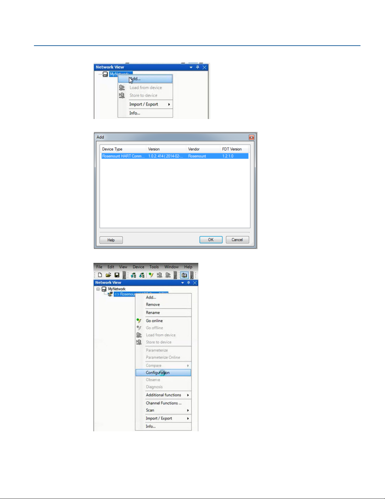
3. Right click My Network, and then select Add....
4. Select Rosemount HART CommDTM for Device Type and select OK.
5. Under MyNetwork, right click Rosemount HART CommDTM, then select Configuration.
6. Select the correct COM Port.
7. Select the Access Mode dropdown and set to Emulated.
6
Configuration
Page 15

Reference Manual
A
B
C
D
OR
00809-0100-4088, Rev DB
8. Select Self Test to check the connection.
Configuration
April 2018
9. Select OK.
2.2.5 Connecting to a personal computer
Figure 2-1 shows how to connect a device to either a computer with the RTIS or a handheld
communicator.
Figure 2-1. Connecting a Personal Computer to a Transmitter
A. RTIS
B. HART modem
C. Field Communicator
D. User-provided power supply
Config uration
7
Page 16

Configuration
April 2018
1. Wire the device as detailed in Section 3: Installation.
2. Connect the MACTek HART modem to the correct USB communications port on the PC as set up in
“Getting started with RTIS” on page 5.
3. Remove the cover of the transmitter above the side marked “FIELD TERMINALS.”
4. Connect the mini-grabber connectors to the “LOCAL (HART)” terminals.
Explosions can cause death or serious injury.
Do not remove the instrument cover in explosive atmospheres when the circuit is live.
2.3 Launching the configuration process
This section outlines how to configure the transmitter using the RTIS.
1. Right click Rosemount HART CommDTM, select Scan, then select Create Network.
Reference Manual
00809-0100-4088, Rev DB
8
Configuration
Page 17

Reference Manual
00809-0100-4088, Rev DB
The DTM setup is complete.
2. Right click on the transmitter, then select Go Online. Your device is now online.
Configuration
April 2018
3. Right click on the transmitter again, select Parameterize Online, then select Configure/Setup.
Config uration
9
Page 18

Configuration
April 2018
2.4 Basic device configuration
The Guided Setup section provides procedures to commission the transmitter. The Basic Setup button
can be used to perform all of the required transmitter configuration. See Table 2-2 on page 33 for the
complete list of Field Communicator for basic setup.
Figure 2-2. Guided Setup Tab
Reference Manual
00809-0100-4088, Rev DB
All screens in this section are shown for measurement type 1 (differential pressure, static pressure
[absolute], and process temperature) with LCD display. Field Communicator are given for a transmitter
with Measurement type 1. Field Communicator and screens for other multivariable types and
measurement types may vary.
Note
All screens in this section are shown using the RTIS. Edited information is not sent to the transmitter until
the Send button is selected.
2.4.1 Units of measure and damping
Fast Keys
The damping command changes the response time of the transmitter; higher values can smooth
variations in output readings caused by rapid input changes. Determine the appropriate damping setting
based on the necessary response time, signal stability, and other requirements. The damping command
utilizes floating point configuration allowing the user to input any damping value between 0 and 60
seconds.
The units and damping for each process variable may be edited by selecting Manual Setup in the menu
tree and then the appropriate tab as detailed below:
Under the Differential Pressure tab, the Units and Damping for the Differential Pressure may be edited.
Under the Static Pressure tab, the Units and Damping for the Static Pressure may be edited.
Units: 2, 1, 1, 2
Damping: 2, 1, 1, 3
10
Configuration
Page 19

Reference Manual
00809-0100-4088, Rev DB
Note
Both absolute and gage pressure are available as variables. The type of transmitter ordered will
determine which variable is measured and which is calculated based on the user defined atmospheric
pressure. For more information on configuring the atmospheric pressure, see “Static pressure” on
page 16. Since only one of the static pressures is actually being measured, there is a single damping
setting for both variables which may be edited under the Static Pressure tab.
Under the Process Temperature tab, the Units and Damping for the Process Temperature may be edited.
Under the Module Temperature tab, the Units for the Module Temperature may be set. The sensor
module temperature measurement is taken within the module, near the differential pressure and/or
static pressure sensors and can be used to control heat tracing or diagnose device overheating.
2.4.2 Network
Configuration
April 2018
Fast Keys
2, 2, 6, 1
Device address
In the Network tab, the Device Address field can be used to set the device's address under the Modbus®
Configuration heading.
Figure 2-3. Network Tab
Config uration
Baud rates
The baud rate is user selectable under the Modbus Configuration heading.
For default and available baud rates, see “Baud rate (software configurable)” on page 57.
Turn around delay
The Turnaround Delay Time (ms) field can be used to configure the device’s turnaround delay time. For
more information, reference “Communications” on page 62.
11
Page 20

Configuration
April 2018
2.5 Detailed device configuration
2.5.1 Display
Reference Manual
00809-0100-4088, Rev DB
Fast Keys
The LCD display features a four-line display. The first line of five characters displays the output
description, the second line of seven digits displays the actual value, and the third line of six characters
displays engineering units. The fourth line displays “Error” when there is a problem detected within the
transmitter. The LCD display can also display diagnostic messages. These diagnostic messages are listed
in “Alarms and conditions” on page 115.
The Display tab allows the user to configure which variables will be shown on the LCD display. Click the
check box next to each variable to select a variable for display. The transmitter will scroll through the
selected variables, showing each for three seconds as a default setting.
Figure 2-4. Display Tab
2, 2, 5
12
The Display tab includes three types of display options (information that appears on the LCD display)
including Device Variables, User-Defined Parameters, or User-Defined Variables.
Device variables
The device variables include Differential Pressure, Absolute Temperature, Gage Pressure, Process
Temperature, Module Temperature, Device Address or Baud Rate. These display variables can be selected
or deselected on the left column of the Display Options heading.
User-defined parameters
The User-Defined Parameters fields are for pieces of information the device can store for reference. The
device will not modify or update these parameters but they can be written by the user or a host system to
be displayed on the LCD display and include Beta Ratio, Pipe Schedule, or Orifice Bore. If the device loses
power at any point during operation, these values are stored in memory and will not be lost.
Configuration
Page 21

Reference Manual
00809-0100-4088, Rev DB
To configure User-Defined Parameters, select Configure User-Defined Parameters.
A screen will appear as shown below:
Each parameter can be given a label, value and unit to be stored inside the device.
Configuration
April 2018
User-defined variables
Note
Only the value of the user-defined variables should be written on a periodic basis. Regular writes to the
other parameters may cause the device memory to fail.
The User-Defined Variable fields are for pieces of information that the device can store for a live reference
of the application status or production levels, via Modbus. The device itself will not modify or update
these variables; rather this is intended to be a live value sent to the device from a host, such as a flow
computer or Remote Terminal Unit (RTU). This information can then be displayed on the device's LCD
display and include variables such as Last 24-Hours of Gas Volume or Instantaneous Flow Rate.
To configure User-Defined Variables, select Configure User-Defined Variables. A screen will appear as
shown below:
Config uration
13
Page 22

Configuration
April 2018
Similar to the User-Defined Parameters screen, you can input a label and unit for each variable, however
the value will be written by the flow computer or host. The user must program the flow computer or host
separately to write the value to the device. If the device loses power at any point during operation, the
value will be lost, but the Label and Units will not be lost.
Note
If the transmitter is ordered without an LCD display, the User-Defined Parameters and User-Defined
Variables are still available but are configured through the User-Defined Data tab in Manual Setup rather
than accessing them through the Display tab.
LCD display scroll time
The LCD display scroll time controls the amount of time each variable is displayed on the LCD display.
2.5.2 Device information
Reference Manual
00809-0100-4088, Rev DB
Fast Keys
The Device Information tab displays the device identification information on one screen including tags,
model numbers and assembly information.
Figure 2-5. Device Information Tab
2, 2, 7
2.5.3 Overview variables
Fast Keys
The Overview Variables tab allows the user to set which variables are displayed on the RTIS Overview
screen.
14
2, 2, 8
Configuration
Page 23

Reference Manual
00809-0100-4088, Rev DB
Figure 2-6. Overview Variables Tab
2.5.4 Alert setup
Configuration
April 2018
Fast Keys
The Alert Configuration tab is found under the Alert Setup menu of the device’s configuration menu. From
this tab, the user can configure upper and lower alert levels for each of the measured variables. This
includes the Differential Pressure, Static Pressure (Absolute or Gage), Module Temperature, or Process
Tem p er at ur e.
Figure 2-7. Alert Configuration Tab
2, 3
Config uration
15
Page 24

Configuration
April 2018
2.6 Variable configuration
2.6.1 Differential pressure
Reference Manual
00809-0100-4088, Rev DB
Fast Keys
Note
For Differential pressure sensor calibration , see page 106.
Figure 2-8. Differential Pressure Tab
2, 2, 1
1. Under the Setup heading, edit the Units, Damping, and Low DP Cutoff as needed.
2. Under the Reading heading, view the Differential Pressure and status.
3. Under the Sensor Limits heading, view the Upper, Lower, and Minimum Span.
2.6.2 Static pressure
Fast Keys
Note
For Static pressure sensor calibration , see page 109.
16
2, 2, 2
Configuration
Page 25

Reference Manual
00809-0100-4088, Rev DB
Figure 2-9. Static Pressure Tab
Configuration
April 2018
1. Under the Sensor Type heading, view whether the sensor is an Absolute Pressure Sensor or a Gage
Pressure Sensor.
2. Under the Setup heading for Static Pressure, edit the Units, Damping, and User-Defined Atmospheric
Pressure as needed.
3. Under the Absolute Pressure Setup and Gage Pressure Setup heading, view the Pressure, Status, Upper,
Lower, and Minimum Span for both Absolute and Gage Pressure respectively.
2.6.3 Process temperature
Fast Keys
Note
For Process temperature sensor calibration , see page 109.
2, 2, 3
Config uration
17
Page 26

Configuration
April 2018
Reference Manual
00809-0100-4088, Rev DB
Figure 2-10. Process Temperature Tab
1. Under the Setup heading for Process Temperature, edit the Units, Damping, and Sensor Type as
needed.
Note
The Rosemount 4088 accepts either a 3-wire or 4-wire RTD sensor, which can be selected under Sensor
Type. Ensure the type of sensor being used is selected or an RTD Sensor Type Mismatch will occur. For
more information about wiring the RTD, see “Install optional process temperature input (Pt 100 RTD
Sensor)” on page 47.
2. Under the Reading heading, view the Process Temperature and status.
3. Select the Tem per at ur e Mode under the Mode Setup heading. See Ta bl e 2 -1 for mode types and
descriptions.
Table 2-1. Temperature Modes
Temperature mode Description
Normal
Backup
Fixed
The transmitter will only use the actual measured Process Temperature value. If the
temperature sensor fails, the transmitter process temperature will be NAN (not a
number).
The transmitter will use the actual measured Process Temperature value. If the
temperature sensor fails, the transmitter will use the value shown in the Fixed/Backup
Tem pera ture field.
The transmitter will always use the temperature value shown in the Fixed/Backup
Tem pera ture field.
18
The Rosemount 4088 accepts Callendar-Van Dusen constants from a calibrated RTD schedule and
generates a special custom curve to match that specific sensor resistance vs. temperature performance.
Configuration
Page 27

Reference Manual
00809-0100-4088, Rev DB
Matching the specific sensor curve with the transmitter configuration enhances the temperature
measurement accuracy.
4. Under the Sensor Matching heading, view the Callendar-Van Dusen constants R0, A, B, and C. If the
Callendar-Van Dusen constants are known for the user’s specific Pt 100 RTD sensor, the constants R0,
A, B, and C may be edited by selecting the Callendar-Van Dusen Setup button and following the
on-screen prompts.
The user may also view the α, β, and d coefficients by selecting the View Alpha, Beta, Delta button. The
constants R0, α, β, and d may be edited by selecting the Callendar-Van Dusen Setup button and
following the on-screen prompts. To reset the transmitter to the IEC 751 Defaults, select the Reset to IEC
751 Defaults button.
5. Under the Process Temperature Sensor Limits heading, view and edit the Upper and Lower Sensor
Limits. Process Temperature Sensor Limits allow for early detection of RTD failures or abnormal
process conditions.
2.6.4 Module temperature
Configuration
April 2018
Fast Keys
The sensor module temperature variable is the measured temperature of the sensors and electronics
within the sensor module assembly. The module temperature value can be used to control heat tracing
or diagnose device overheating.
Figure 2-11. Module Temperature Tab
2, 2, 4
Config uration
1. Under the Setup heading, edit the Units as needed.
2. Under the Reading heading, view the Module Temperature and status.
3. After the Sensor Limits heading, view the Upper and Lower Module Temperature Limits.
19
Page 28

Configuration
April 2018
2.7 Menu trees and Field Communicator
Based on the configuration ordered, some measurements (i.e. static pressure, process temperature) may
not be available. Available measurements are determined by the Multivariable Type and Measurement
Type codes ordered. See ordering information in the Product Data Sheet for more information.
The menu trees and Field Communicator in this section are shown for the following model code:
Measurement type 1 (differential pressure, static pressure [absolute], process temperature) with LCD
display
The menu trees and Field Communicator for other model codes will vary.
Reference Manual
00809-0100-4088, Rev DB
20
Configuration
Page 29

Reference Manual
00809-0100-4088, Rev DB
2.7.1 Rosemount 4088A menu tree
Figure 2-12. Overview
Configuration
April 2018
Config uration
21
Page 30

Configuration
April 2018
Figure 2-13. Configure – Guided Setup
Reference Manual
00809-0100-4088, Rev DB
22
Configuration
Page 31

Reference Manual
00809-0100-4088, Rev DB
Figure 2-14. Configure – Manual Setup
Configuration
April 2018
Config uration
23
Page 32

Configuration
April 2018
Figure 2-15. Configure – Manual Setup (Continued)
Reference Manual
00809-0100-4088, Rev DB
24
Configuration
Page 33

Reference Manual
00809-0100-4088, Rev DB
Figure 2-16. Service Tools
Configuration
April 2018
Config uration
25
Page 34

Configuration
April 2018
Figure 2-17. Service Tools (continued)
Reference Manual
00809-0100-4088, Rev DB
26
Configuration
Page 35

Reference Manual
00809-0100-4088, Rev DB
2.7.2 Rosemount 4088B menu tree
Figure 2-18. Overview
Configuration
April 2018
Config uration
27
Page 36

Configuration
April 2018
Figure 2-19. Configure – Guided Setup
Reference Manual
00809-0100-4088, Rev DB
28
Configuration
Page 37

Reference Manual
00809-0100-4088, Rev DB
Figure 2-20. Configure – Manual Setup
Configuration
April 2018
Config uration
29
Page 38

Configuration
April 2018
Figure 2-21. Configure – Manual Setup (Continued)
Reference Manual
00809-0100-4088, Rev DB
30
Configuration
Page 39

Reference Manual
00809-0100-4088, Rev DB
Figure 2-22. Service Tools
Configuration
April 2018
Config uration
31
Page 40

Configuration
April 2018
Figure 2-23. Service Tools (Continued)
Reference Manual
00809-0100-4088, Rev DB
32
Configuration
Page 41

Reference Manual
00809-0100-4088, Rev DB
2.7.3 Field Communicator
A check () indicates the basic configuration parameters. At a minimum, these parameters should be
verified as part of the configuration and startup procedure.
Table 2-2. Field Communication Fast Keys
Category Function Sequence
Device Available Measurements 1, 9, 4
Device Display 2, 2, 5
Device Sensor Module Temperature 2, 2, 4
Device Sensor Module Temperature Units 2, 2, 4, 3
Device Sensor Module Temperature Upper Alert Limit 2, 2, 4, 4
Device Sensor Module Temperature Lower Alert Limit 2, 2, 4, 5
Device Device Address 2, 2, 6, 1, 1
Device Device Status 1, 1
Device Baud Rate 2, 2, 6, 1, 2
Device Turnaround Delay 2, 2, 6, 1, 3
Device Ta g 2, 2, 7, 1, 1
Configuration
April 2018
Device Long Tag 2, 2, 7, 1, 2
Device Transmitter S/N 2, 2, 7, 1, 7
Device Security Switch 1, 9, 5, 1
DP Sensor DP 2, 2, 1
DP Sensor Calibration 3, 4, 1, 8
DP Sensor DP Units 2, 2, 1, 3
DP Sensor DP Damping 2, 2, 1, 4
DP Sensor Veri fic atio n 3, 4, 1, 9
DP Sensor Upper Alert Limit 2, 2, 1, 6
DP Sensor Lower Alert Limit 2, 2, 1, 7
PT Sensor Sensor Matching 2, 2, 3, 8
PT Sensor PT 2, 2, 3
PT Sensor Calibration 3, 4, 3, 8
PT Sensor PT Units 2, 2, 3, 3
PT Sensor PT Damping 2, 2, 3, 4
PT Sensor Sensor Type 2, 2, 3, 5
PT Sensor Veri fic atio n 3, 4, 3, 9
PT Sensor Upper Alert Limit 2, 2, 3, 6, 1
Config uration
PT Sensor Lower Alert Limit 2, 2, 3, 6, 2
PT Sensor Temp Mode Setup 2, 2, 3, 7
33
Page 42

Configuration
D
C
B
A
D
E
F
G
April 2018
Reference Manual
00809-0100-4088, Rev DB
Table 2-2. Field Communication Fast Keys
Category Function Sequence
SP Sensor AP 2, 2, 2, 7
SP Sensor SP Units 2, 2, 2, 3
SP Sensor GP 2, 2, 2, 6
SP Sensor SP Damping 2, 2, 2, 4
SP Sensor Calibration 3, 4, 2, 8
SP Sensor Veri fic atio n 3, 4, 2, 9
SP Sensor Upper Alert Limit 2, 2, 2, 6, 3
SP Sensor Lower Alert Limit 2, 2, 2, 6, 4
2.8 Rosemount 4088A configuration with legacy tool
The Rosemount 4088A may be configured with the Rosemount 3095FB Configuration Software. When
using this legacy tool, only functionality that was available with the Rosemount 3095FB can be accessed.
The device must be removed from the Modbus network prior to communicating over the RS-485 bus.
Figure 2-24. Transmitter Configuration via RS-485 Network Port
A. RS- 485 (A)
B. RS-485 (B)
C. RS-485 bus, twisted pair required
D. Bus Termination: AC termination on Rosemount 4088 (see “Set the switches” on page 43) or 120 Ω resistor
E. User-provided power supply
F. Rosemount 3095FB configuration software
G. RS 232/RS 485 converter
34
Configuration
Page 43

Reference Manual
00809-0100-4088, Rev DB
Section 3 Installation
Overview . . . . . . . . . . . . . . . . . . . . . . . . . . . . . . . . . . . . . . . . . . . . . . . . . . . . . . . . . . . . . . . . . . . . . . . . . . . . page 35
Safety messages . . . . . . . . . . . . . . . . . . . . . . . . . . . . . . . . . . . . . . . . . . . . . . . . . . . . . . . . . . . . . . . . . . . . . . page 35
Considerations . . . . . . . . . . . . . . . . . . . . . . . . . . . . . . . . . . . . . . . . . . . . . . . . . . . . . . . . . . . . . . . . . . . . . . . page 36
Steps required for quick installation . . . . . . . . . . . . . . . . . . . . . . . . . . . . . . . . . . . . . . . . . . . . . . . . . . . . . page 37
Rosemount 305, 306, and 304 Manifolds . . . . . . . . . . . . . . . . . . . . . . . . . . . . . . . . . . . . . . . . . . . . . . . . page 49
3.1 Overview
Installation
April 2018
The information in this section covers installation considerations for the Rosemount™ 4088
MultiVariable
describe basic installation, wiring, and startup procedures. Dimensional drawings for each transmitter
variation and mounting configuration are included in Appendix A: Reference Data.
™
Transmitter. The Rosemount 4088 Quick Start Guide is shipped with every transmitter to
3.2 Safety messages
Procedures and instructions in this section may require special precautions to ensure the safety of the
personnel performing the operation. Information that raises potential safety issues is indicated with a
warning symbol ( ). Refer to the following safety messages before performing an operation preceded
by this symbol.
Installation
35
Page 44

Installation
April 2018
Reference Manual
00809-0100-4088, Rev DB
Explosions can result in death or serious injury.
Do not remove the transmitter covers in explosive environments when the circuit is live.
Fully engage both transmitter covers to meet explosion-proof requirements.
Before connecting a communicator in an explosive atmosphere, make sure the instruments in the
loop are installed in accordance with intrinsically safe or non-incendive field wiring practices.
Verify the operating atmosphere of the transmitter is consistent with the appropriate hazardous
locations certifications.
Electrical shock can result in death or serious injury.
Avoid contact with the leads and terminals.
Process leaks could result in death or serious injury.
Install and tighten all four flange bolts before applying pressure.
Do not attempt to loosen or remove flange bolts while the transmitter is in service.
Replacement equipment or spare parts not approved by Emerson
reduce the pressure retaining capabilities of the transmitter and may render the instrument
dangerous.
Use only bolts supplied or sold by Emerson as spare parts.
Improper assembly of manifolds to traditional flange can damage sensor module.
For safe assembly of manifold to traditional flange, bolts must break back plane of flange web (i.e., bolt
hole) but must not contact module housing.
Sensor module and electronics housing must have equivalent approval labeling in order to
maintain hazardous location approvals.
When upgrading, verify sensor module and electronics housing certifications are equivalent.
Differences in temperature class ratings may exist, in which case the complete assembly takes the
lowest of the individual component temperature classes (for example, a T4/T5 rated electronics
housing assembled to a T4 rated sensor module is a T4 rated transmitter).
™
for use as spare parts could
3.3 Considerations
3.3.1 General
Measurement performance depends upon proper installation of the transmitter and impulse piping.
Mount the transmitter close to the process and use minimum piping to achieve best performance. Also,
consider the need for easy access, personnel safety, practical field calibration, and a suitable transmitter
environment. Install the transmitter to minimize vibration, shock, and temperature fluctuation.
Important
Install the enclosed pipe plug (found in the box) in the unused conduit opening. For straight threads, a
minimum of six threads must be engaged. For tapered threads, install the plug wrench-tight.
For material compatibility considerations, see the Material Selection Tech n ical Note.
36
Installation
Page 45

Reference Manual
00809-0100-4088, Rev DB
3.3.2 Mechanical
Steam service
For steam service or for applications with process temperatures greater than the limits of the
transmitter, do not blow down impulse piping through the transmitter. Flush lines with the blocking
valves closed and refill lines with water before resuming measurement.
Side mounting
When the transmitter is mounted on its side, position the coplanar flange to ensure proper venting or
draining. Mount the flange as shown in Figure 3-5 on page 41, keeping drain/vent connections on the
bottom for gas service and on the top for liquid service.
3.3.3 Environmental
Best practice is to mount the transmitter in an environment that has minimal ambient temperature
change. The transmitter electronics temperature operating limits are –40 to 185 °F (–40 to 85 °C).
Appendix A: Reference Data lists the sensing element operating limits. Mount the transmitter so it is not
susceptible to vibration and mechanical shock and does not have external contact with corrosive
materials.
Installation
April 2018
3.4 Steps required for quick installation
Start >
Mount the transmitter
Consider housing rotation
Set the switches
Wiring and power up
Verify device configuration
Trim the transmitter
> Finish
Installation
37
Page 46

Installation
Flow
April 2018
3.4.1 Mount the transmitter
Liquid flow applications
1. Place taps to the side of the line.
2. Mount beside or below the taps.
3. Mount the transmitter so that the drain/vent
valves are oriented upward.
Gas flow applications
1. Place taps in the top or side of the line.
2. Mount beside or above the taps.
Reference Manual
00809-0100-4088, Rev DB
Flow
Steam flow applications
1. Place taps to the side of the line.
2. Mount beside or below the taps.
3. Fill impulse lines with water.
Flow
Flow
38
Installation
Page 47

Reference Manual
00809-0100-4088, Rev DB
Figure 3-1. Mounting Bracket – Coplanar Flange
Figure 3-2. Mounting Brackets – Traditional Flange
Installation
April 2018
Panel mount Pipe mount
Panel mount Pipe mount
Installation
Figure 3-3. Mounting Brackets – In-line
Panel mount Pipe mount
39
Page 48

Installation
April 2018
Reference Manual
00809-0100-4088, Rev DB
Bolting considerations
If the transmitter installation requires assembly of a process flange, manifold, or flange adapters, follow
these assembly guidelines to ensure a tight seal for optimal performance characteristics of the
transmitter. Only use bolts supplied with the transmitter or sold by Emerson as spare parts. Figure 3-4
illustrates common transmitter assemblies with the bolt length required for proper transmitter
assembly.
Figure 3-4. Common Transmitter Assemblies
A
4 × 1.75-in.
(44 mm)
B
C
4 × 1.75-in.
(44 mm)
D
4 × 2.25-in.
(57 mm)
4 × 1.50-in.
(38 mm)
4 × 1.75-in.
(44 mm)
4 × 2.88-in.
(73 mm)
A. Transmitter with coplanar flange
B. Transmitter with coplanar flange and optional flange adapters
C. Transmitter with traditional flange and optional flange adapters
D. Transmitter with coplanar flange and optional manifold and flange adapters
Note
For all other manifolds, contact Customer Central technical support.
Bolts are typically carbon steel or stainless steel. Confirm the material by viewing the markings on the
head of the bolt and referencing Table 3-1 on page 41. If bolt material is not shown in Tab l e 3- 1 , contact
the local Emerson representative for more information.
Use the following bolt installation procedure:
1. Carbon steel bolts do not require lubrication and the stainless steel bolts are coated with a lubricant
to ease installation. However, no additional lubricant should be applied when installing either type of
bolt.
2. Finger-tighten the bolts.
3. Torque the bolts to the initial torque value using a crossing pattern. See Ta b le 3 - 1 for initial torque
value.
4. Torque the bolts to the final torque value using the same crossing pattern.
See Ta bl e 3 -1 for final torque value.
40
5. Verify the flange bolts are protruding through the sensor module before applying pressure (see
Figure 3-5 on page 41).
Installation
Page 49

Reference Manual
A
B
A
B
C
D
00809-0100-4088, Rev DB
Table 3-1. Torque Values for the Flange and Flange Adapter Bolts
Bolt material Head markings Initial torque Final torque
Installation
April 2018
B8M
B7M
316
Carbon Steel (CS) 300 in-lb 650 in-lb
316
Stainless Steel (SST) 150 in-lb 300 in-lb
316
STM
R
316
SW
316
Figure 3-5. Proper Bolt Installation
A. Bolt
B. Sensor module
O-rings with flange adapters
Failure to install proper flange adapter O-rings may cause process leaks, which can result in death or
serious injury. Only use the O-ring that is designed for its specific flange adapter.
A. Flange adapter
B. O-ring
C. PTFE-based profile (square)
D. Elastomer profile (round)
Whenever the flange or adapters are removed, visually inspect the O-rings. Replace them if there are
any signs of damage, such as nicks or cuts. If the O-rings are replaced, re-torque the flange bolts and
alignment screws after installation to compensate for seating of the O-rings.
In-line gage transmitter orientation
The low side pressure port (atmospheric reference) on the in-line gage transmitter is located under the
sensor module neck label. (See Figure 3-6 on page 42)
Keep the vent path free of any obstruction, including but not limited to paint, dust, and lubrication by
mounting the transmitter so that any contaminants can drain away.
Installation
41
Page 50

Installation
A
A
B
April 2018
Figure 3-6. In-line Gage Transmitter
A. Low side pressure port (under neck label)
3.4.2 Consider housing rotation
To improve field access to wiring or to better view the optional LCD display:
Reference Manual
00809-0100-4088, Rev DB
1. Loosen the housing rotation set screw.
2. Turn the housing up to 180° left or right of its original (as shipped) position.
3. Re-tighten the housing rotation set screw.
Figure 3-7. Transmitter Housing Set Screw
A. LCD display
B. Housing rotation set screw (
3
/32-in.)
Note
Do not rotate the housing more than 180° without first performing a disassembly procedure (refer to
Section 6: Troubleshooting for more information). Over-rotation may sever the electrical connection
between the sensor module and the electronics.
Rotate the LCD display
Transmitters ordered with the LCD display will be shipped with the display installed.
In addition to housing rotation, the optional LCD display can be rotated in 90° increments by squeezing
the two tabs, pulling out, rotating and snapping back into place.
If LCD display pins are inadvertently removed from the electronics board, carefully re-insert the pins
before snapping the LCD display back into place.
Use the following procedure and Figure 3-8 on page 43 to install the LCD display:
42
Installation
Page 51

Reference Manual
AB
00809-0100-4088, Rev DB
1. If the transmitter is installed in a loop, then secure the loop and disconnect power.
2. Remove the transmitter cover on the electronics board side (opposite the field terminals side). Do not
remove instrument covers in explosive environments when circuit is live.
3. Engage the four-pin connector into the electronics board and snap LCD display into place.
4. In order to meet explosion-proof requirements, reinstall the housing cover and tighten so the cover is
fully seated with metal to metal contact between the housing and cover. After the cover is seated
properly, replace the flathead screw located on the bottom of the housing cover.
Figure 3-8. Optional LCD Display
A. Electronics board
B. LCD display
C. Display cover
Installation
April 2018
A
B
C
3.4.3 Set the switches
The transmitter’s default configuration for the AC Termination is in the off position. The transmitter’s
electronics board default configuration for the Security switch is in the off position.
1. If the transmitter is installed, secure the bus and remove power.
2. Remove the transmitter cover opposite the field terminal side. Do not remove the instrument covers
in explosive environments when the circuit is live.
3. Slide the Security and AC Termination switches into the preferred position by using a small
screwdriver.
Note
The Security switch will need to be in the off position in order to make any configuration changes.
4. In order to meet explosion-proof requirements, reinstall the housing cover and tighten so the cover is
fully seated with metal to metal contact between the housing and cover. After the cover is seated
properly, replace the flathead screw located on the bottom of the housing cover.
Figure 3-9. Transmitter Switch Configuration
A. Security
B. AC termination
Installation
43
Page 52

Installation
April 2018
3.4.4 Wiring and power up
Use the following steps to wire the transmitter:
1. Remove the cover on the field terminals side of the housing.
2. Set up based on optional process temperature input.
a. If the optional process temperature input is being utilized, follow the procedure “Install optional
process temperature input (Pt 100 RTD Sensor)” on page 47.
b. If there will not be an optional process temperature input, plug and seal the unused conduit
connection.
Note
When the enclosed threaded plug is utilized in the conduit opening, it must be installed with a minimum
engagement of five threads in order to comply with explosion-proof requirements. For straight threads,
a minimum of six threads must be engaged. For tapered threads, install the plug wrench-tight.
3. Connect the Rosemount 4088A to the RS-485 bus as shown in Figure 3-10 (for Rosemount 4088B
wiring and power up instructions, reference the ROC and FloBoss Manuals outlined in “Rosemount
4088B ROC communications” on page 77 or the ControlWave Manual outlined in “Rosemount 4088B
BSAP communications”).
a. Connect the A lead to the “A” terminal.
b. Connect the B lead to the “B” terminal.
Reference Manual
00809-0100-4088, Rev DB
4. Connect the positive lead from the power source to the “PWR +” terminal, and the negative lead to
the “PWR –” terminal (for power requirements, reference the Product Data Sheet).
Note
The Rosemount 4088A uses RS-485 Modbus
baud rate is 9600.
Note
Twisted pair wiring is required for RS-485 bus wiring. Wiring runs under 1000 ft (305 m) should be AWG
22 or larger. Wiring runs from 1000 to 4000 ft. (305 to 1219 m) should be AWG 20 or larger. Wiring
should not exceed AWG 16.
5. Reinstall the housing cover and tighten so the cover is fully seated with metal to metal contact
between the housing and cover in order to meet explosion-proof requirements.
Note
Installation of the transient protection terminal block does not provide transient protection unless the
transmitter housing is properly grounded.
®
with eight data bits, one stop bit and no parity. The default
44
Installation
Page 53

Reference Manual
D
D
B
A
C
E
00809-0100-4088, Rev DB
Transmitter wiring
Figure 3-10. Transmitter Wiring for RS-485 Bus
Installation
April 2018
A. RS- 485 (A)
B. RS-485 (B)
C. RS-485 bus, twisted pair required
D. Bus Termination: AC Termination on Rosemount 4088
(see “Set the switches” on page 43) or 120 Ω resistor
E. User-provided power supply
To co nfigure tr ansmitter via H A RT® port, reference Figure 2-1 on page 7 for the wiring diagram.
To configure using RS-485 network port, reference Figure 2-24 on page 34 for the wiring diagram.
Grounding
Signal wire grounding
Do not run signal wiring in conduit or open trays with power wiring, or near heavy electrical equipment.
If shielded wiring is used, ground the shield of the signal wiring at any one point on the signal loop.
Device must be properly grounded or earthed according to local electric codes.
Transmitter case
Always ground the transmitter case in accordance with national and local electrical codes. The most
effective transmitter case grounding method is a direct connection to earth ground with minimal
impedance (< 1 Ω). Methods for grounding the transmitter case include:
Internal ground connection
The internal ground connection screw is inside the terminal side of the electronics housing. The screw is
identified by a ground symbol ( ).
Figure 3-11. Internal Ground Connection
A
Installation
A. Ground lug
45
Page 54

Installation
April 2018
Reference Manual
00809-0100-4088, Rev DB
External ground connection
The external ground connection is on the outside of the sensor module housing. The connection is
identified by a ground symbol ( ). An external ground assembly is included with the option codes
shown in Table 3-2 on page 46 or is available as a spare part (03151-9060-0001).
Figure 3-12. External Ground Connection
B
A
A. External ground lug
B. External ground assembly (03151-9060-0001)
Table 3-2. External Ground Screw Approval Option Codes
Option code Description
E1 AT EX Flamep roo f
I1 ATEX Intrinsic Safety
N1 ATE X Type n
ND ATE X Dus t
K1 ATEX Flameproof, Intrinsic Safety, Type n, Dust (combination of E1, I1, N1, and ND)
E7 IECEx Flameproof, Dust Ignition-proof
N7 IECEx Type n
K7 IECEx Flameproof, Dust Ignition-proof, Intrinsic Safety, and Type n (combination of E7, I7, and N7)
KA ATEX and CSA Explosion-proof, Intrinsically Safe, Division 2 (combination of E1, E6, I1, and I6)
KC FM and ATEX Explosion-proof, Intrinsically Safe, Division 2 (combination of E5, E1, I5, and I1)
T1 Transient terminal block
D4 External ground screw assembly
Surges/transients
The transmitter will withstand electrical transients of the energy level usually encountered in static
discharges or induced switching transients. However, high-energy transients, such as those induced in
wiring from nearby lightning strikes, can damage the transmitter.
Optional transient protection terminal block
The transient protection terminal block can be ordered as an installed option (option code T1 in the
transmitter model number) or as a spare part to retrofit existing Rosemount 4088 MultiVariable
Transmitters in the field. For a complete listing of spare part numbers for transient protection terminal
blocks, refer to “Spare parts list” on page 123. A lightning bolt symbol on a terminal block identifies it as
having transient protection.
46
Installation
Page 55

Reference Manual
00809-0100-4088, Rev DB
Note
Grounding the transmitter case using the threaded conduit connection may not provide a sufficient
ground. The transient protection terminal block (option code T1) will not provide transient protection
unless the transmitter case is properly grounded. See “Grounding” on page 45 to ground the transmitter
case. Do not run transient protection ground wire with signal wiring; the ground wire may carry
excessive current if a lightning strike occurs.
Optional extended cover
The Rosemount 4088 can also be ordered with an aluminum or SST extended cover. The extended cover
option is beneficial in applications where more space is needed to wire the transmitter. The extended
cover can be ordered as an installed option (option code HX under housing cover extension) or as a spare
part to retrofit existing Rosemount 4088 MultiVariable Transmitters in the field. For a complete list of the
spare part numbers for covers, refer to “Spare parts list” on page 123.
Install optional process temperature input
(Pt 100 RTD Sensor)
Note
To meet ATEX/IECEx Flameproof certification, only ATEX/IECEx Flameproof cables (temperature input
code C30, C32, C33, or C34) may be used.
Installation
April 2018
1. Mount the Pt 100 RTD Sensor in the appropriate location.
Note
Use shielded 4- or 3-wire cable for the process temperature connection.
2. Connect the RTD cable to the transmitter by inserting the cable wires through the unused housing
conduit and connect to the screws on the transmitter terminal block. An appropriate cable gland
should be used to seal the conduit opening around the cable.
Note
If power is already connected to the Rosemount 4088, power should be removed prior to connecting the
RTD wires. This will allow the Rosemount 4088 to detect the RTD type at startup. Once the RTD is
installed, reconnect power.
Installation
47
Page 56

Installation
April 2018
3. Connect the RTD cable shield wire to the ground lug in the housing.
Figure 3-13. Transmitter RTD Wiring Connection
3-wire 4-wire
A
A
Reference Manual
00809-0100-4088, Rev DB
Red
B
A. Ground lug
B. Pt 100 RTD sensor
C. Connection head
White
C
B
Red
Note
Verify the installed PT sensor type (3-wire or 4-wire) matches the device setting.
3.4.5 Verify device configuration
For Rosemount 4088A, use Rosemount Transmitter Interface Software with the Rosemount 4088 DTM
or a HART Field Communicator with the Rosemount 4088 Device Descriptor to communicate with and
verify configuration of the transmitter.
For Rosemount 4088B, use ROCLINK
and verify configuration of the transmitter.
™
, TechView, or HART Field Communicator to communicate with
White
C
Note
A list of parameters to verify during commissioning is listed in “Field Communicator” on page 33.
3.4.6 Trim the transmitter
Transmitters are shipped fully calibrated per request or by the factory default.
Zero trim
A zero trim is a single-point adjustment used for compensating mounting position and line pressure
effects on static and differential pressure sensors. When performing a zero trim, ensure that the
equalizing valve is open and all wet legs are filled to the correct level.
If zero offset is less than 5 percent of USL, follow the user interface software instructions below to
perform a zero trim on a Field Communicator or see the “Zero trim” on page 105 for PC configuration.
Performing a zero trim using the Field Communicator
1. Block, equalize, and vent the transmitter and connect the Field Communicator (for more information
on connecting the Field Communicator, see Figure 2-1 on page 7).
2. If the device is equipped with a static pressure sensor, trim the sensor by inputting the following Fast
48
Installation
Page 57

Reference Manual
00809-0100-4088, Rev DB
Key sequence at the transmitter menu:
Installation
April 2018
Field Communicator
3. Follow the appropriate static pressure trim procedure.
Zero trim for gage pressure sensors
or
Lower sensor trim for absolute pressure sensors
Note
It is possible to degrade the performance of the transmitter if the full sensor trim is done improperly or
with inaccurate calibration equipment. Use a pressure input source that is at least three times more
accurate than the transmitter and allow the pressure input to stabilize for ten seconds before entering
any values.
4. Zero the differential pressure sensor by inputting the following Fast Key sequence at the transmitter
menu:
Field Communicator
5. Follow the zero DP trim procedure.
3, 4, 2, 8
3, 4, 1, 8, 5
3.5 Rosemount 305, 306, and 304 Manifolds
The Rosemount 305 Integral Manifold mounts directly to the transmitter and is available in two styles:
traditional and coplanar. The traditional Rosemount 305 can be mounted to most primary elements in
the market today using mounting adapters.
The Rosemount 306 Integral Manifold is used with in-line transmitters to provide block-and-bleed valve
capabilities of up to 10000 psi (690 bar).
The Rosemount 304 conventional manifold combines a traditional flange and manifold that can be
mounted to most primary elements.
3.5.1 Rosemount 305 Integral Manifold installation procedure
To install a Rosemount 305 to a Rosemount 4088:
1. Inspect the PTFE sensor module O-rings. If the O-rings are undamaged, reusing them is
recommended. If the O-rings are damaged (if they have nicks or cuts, for example), replace them with
new O-rings.
Important
If replacing the O-rings, be careful not to scratch or deface the O-ring grooves or the surface of the
isolating diaphragm when removing the damaged O-rings.
2. Install the integral manifold on the sensor module. Finger tighten the bolts, then tighten the bolts
incrementally in a cross pattern (see Figure 3-14) to final torque value. See Table 6-4 on page 122 for
complete bolt installation information and for torque values. When fully tightened, the bolts should
extend through the top of the module housing plane of the flange web (i.e. bolt hole) but must not
contact the module housing.
Installation
49
Page 58

Installation
April 2018
3. If the PTFE sensor module O-rings have been replaced, the flange bolts should be re-tightened after
installation to compensate for cold flow of the O-rings.
4. If applicable, install flange adapters on the process end of the manifold using the 1.75-in. flange bolts
supplied with the transmitter.
Note
Always perform a zero trim on the transmitter/manifold assembly after installation to eliminate
mounting effects. See “Zero trim” on page 48.
Reference Manual
00809-0100-4088, Rev DB
3.5.2 Rosemount 306 In-line Manifold installation procedure
The Rosemount 306 is for use only with a Rosemount 4088 In-line Transmitter.
Assemble the Rosemount 306 to the Rosemount 4088 with a thread sealant.
1. Place transmitter into holding fixture.
2. Apply appropriate thread paste or tape to threaded instrument end of the manifold.
3. Count total threads on the manifold before starting assembly.
4. Start turning the manifold by hand into the process connection on the transmitter.
Note
If using thread tape, be sure the thread tape does not strip when the manifold assembly is started.
5. Wrench tighten manifold into process connection.
Note
Minimum torque value is 425 in-lb.
6. Count how many threads are still showing.
Note
Minimum engagement is three revolutions.
7. Subtract the number of threads showing (after tightening) from the total threads to calculate the
revolutions engaged. Further tighten until a minimum of three rotations is achieved.
8. For block and bleed manifold, verify the bleed screw is installed and tightened. For 2-valve manifold,
verify the vent plug is installed and tightened.
9. Leak-check assembly to maximum pressure range of transmitter.
3.5.3 Rosemount 304 Conventional Manifold installation procedure
To install a Rosemount 304 to a Rosemount 4088:
1. Align the conventional manifold with the transmitter flange. Use the four manifold bolts for
alignment.
50
2. Finger tighten the bolts, then tighten the bolts incrementally in a cross pattern (see Figure 3-14) to
final torque value. See Table 6-4 on page 122 for complete bolt installation information and for
torque values. When fully tightened, the bolts should extend through the top of the module housing
plane of the flange web (i.e. bolt hole) but must not contact the module housing.
3. If applicable, install flange adapters on the process end of the manifold using the 1.75-in. flange bolts
supplied with the transmitter.
Installation
Page 59

Reference Manual
00809-0100-4088, Rev DB
Figure 3-14. Bolt Tightening Pattern
3.5.4 Rosemount 305 and 304 Manifold styles
The Rosemount 305 Integral Manifold is available in two styles: coplanar and traditional. The traditional
Rosemount 305 can be mounted to most primary elements with mounting adapters.
Figure 3-15. Rosemount 305 Manifold Styles
Integral coplanar Integral traditional
Installation
April 2018
The Rosemount 304 comes in two basic styles: traditional (flange + flange and flange + pipe) and wafer.
The Rosemount 304 traditional manifold comes in 2-, 3-, and 5-valve configurations. The Rosemount
304 wafer manifold comes in 3- and 5-valve configurations.
Figure 3-16. Rosemount 304 Manifold Styles
Traditiona l Wafer
Installation
51
Page 60

Installation
HL
Drain/Vent
valve
Isolate
(open)
Drain/Vent
valve
Isolate
(closed)
Process
Equalize
(closed)
April 2018
3.5.5 Manifold operation
Improper installation or operation of manifolds may result in process leaks, which may cause death or
serious injury.
Always perform a zero trim on the transmitter/manifold assembly after installation to eliminate any shift
due to mounting effects. See Section 5: Operation and Maintenance, “Sensor trim overview” on
page 105.
Coplanar transmitters
3-valve and 5-valve manifolds
Performing zero trim at static line pressure
In normal operation the two isolate (block) valves
between the process ports and transmitter will be open
and the equalize valve will be closed.
Drain/Vent
valve
Isolate
(open)
Reference Manual
00809-0100-4088, Rev DB
HL
Drain/Vent
Equalize
(closed)
valve
Isolate
(open)
1. To zero trim the transmitter, close the isolate valve on
the low side (downstream) side of the transmitter.
2. Open the equalize valve to equalize the pressure on
both sides of the transmitter. The manifold is now in
the proper configuration for performing a zero trim
on the transmitter.
3. After performing a zero trim on the transmitter, close
the equalize valve.
Drain/Vent
valve
Isolate
(open)
Drain/Vent
valve
Isolate
(open)
Process
HL
Drain/Vent
Equalize
(open)
Process
HL
Equalize
(closed)
valve
Isolate
(closed)
Drain/Vent
valve
Isolate
(closed)
52
Process
Installation
Page 61

Reference Manual
HL
(Plugged)
Isolate
(open)
Isolate
(open)
(Plugged)
Equalize
(closed)
Equalize
(closed)
Process ProcessDrain vent
(closed)
HL
(Plugged)
Isolate
(open)
Isolate
(closed)
(Plugged)
Process ProcessDrain vent
(closed)
Equalize
(closed)
Equalize
(closed)
(Plugged)
Isolate
(open)
Equalize
(open)
Equalize
(closed)
Process ProcessDrain vent
(closed)
Isolate
(closed)
(Plugged)
HL
00809-0100-4088, Rev DB
Installation
April 2018
4. Finally, to return the transmitter to service, open the
low side isolate valve.
5-valve natural gas manifold
Performing zero trim at static line pressure
5-valve natural gas configurations shown:
In normal operation, the two isolate (block) valves
between the process ports and transmitter will be open,
and the equalize valves will be closed. Vent valves may be
opened or closed.
Drain/Vent
valve
Isolate
(open)
HL
Drain/Vent
Equalize
valve
(closed)
Isolate
(open)
Process
1. To zero trim the transmitter, first close the isolate valve
2. Open the equalize valve on the high pressure
Installation
on the low pressure (downstream) side of the
transmitter and the vent valve.
(upstream) side of the transmitter.
53
Page 62

Installation
(Plugged)
Isolate
(open)
Equalize
(open)
Equalize
(closed)
Process ProcessDrain vent
(closed)
Isolate
(closed)
(Plugged)
HL
HL
(Plugged)
Isolate
(open)
Isolate
(closed)
(Plugged)
Process ProcessDrain vent
(closed)
Equalize
(closed)
Equalize
(closed)
HL
(Plugged)
Isolate
(open)
Isolate
(open)
(Plugged)
Equalize
(closed)
Equalize
(closed)
Process ProcessDrain vent
(closed)
April 2018
Reference Manual
00809-0100-4088, Rev DB
3. Open the equalize valve on the low pressure
(downstream) side of the transmitter. The manifold is
now in the proper configuration for performing a zero
trim on the transmitter.
4. After performing a zero trim on the transmitter, close
the equalize valve on the low pressure (downstream)
side of the transmitter.
(Plugged)
(open)
HL
Equalize
(open)
Isolate
Process ProcessDrain vent
Equalize
(open)
(closed)
(Plugged)
Isolate
(closed)
5. Close the equalize valve on the high pressure
(upstream) side.
6. Finally, to return the transmitter to service, open the
low side isolate valve and vent valve. The vent valve can
remain open or closed during operation.
54
Installation
Page 63

Reference Manual
Transmitter
Isolate
Vent
(closed)
Process
(open)
Transmitter
Isolate
Vent
(closed)
Process
(closed)
Transmitter
Isolate
Vent
(open)
Process
(closed)
Transmitter
Isolate
Vent
(closed)
Process
(closed)
00809-0100-4088, Rev DB
In-line transmitters
2-valve and block and bleed style manifolds
Isolating the transmitter
In normal operation the isolate (block) valve between the process
port and transmitter will be open and the test/vent valve will be
closed. On a block and bleed style manifold, a single block valve
provides transmitter isolation and a bleed screw provides drain/vent
capabilities.
1. To isolate the transmitter, close the isolate valve.
Installation
April 2018
2. To bring the transmitter to atmospheric pressure, open the vent
valve or bleed screw.
Note
1
A
/4-in. male NPT pipe plug may be installed in the test/vent port
and will need to be removed with a wrench in order to vent the
manifold properly.
Always use caution when venting directly to atmosphere.
3. After venting to atmosphere, perform any required calibration
and then close the test/vent valve or replace the bleed screw.
Installation
55
Page 64

Installation
A
D
C
B
E
F
G
April 2018
Reference Manual
00809-0100-4088, Rev DB
4. Open the Isolate (block) valve to return the transmitter to service.
Transmitter
Vent
(closed)
Isolate
Process
(open)
Adjusting valve packing
Over time, the packing material inside a Rosemount manifold may require adjustment in order to
continue to provide proper pressure retention. Not all manifolds have this adjustment capability. The
manifold model number will indicate what type of stem seal or packing material has been used.
The following steps are provided as a procedure to adjust valve packing:
1. Remove all pressure from device.
2. Loosen manifold valve jam nut.
3. Tighten manifold valve packing adjuster nut
4. Tighten manifold valve jam nut.
1
/4 turn.
5. Re-apply pressure and check for leaks.
6. Above steps can be repeated, if necessary.
If the above procedure does not result in proper pressure retention, the complete manifold should be
replaced.
Figure 3-17. Adjusting Valve Packing
A. Bonnet
B. Ball seat
C. Packing
D. Stem
E. Packing adjuster
F. Jam n ut
G. Packing follower
56
Installation
Page 65

Reference Manual
00809-0100-4088, Rev DB
Section 4 Communication
Rosemount 4088A Modbus communications . . . . . . . . . . . . . . . . . . . . . . . . . . . . . . . . . . . . . . . . . . . . page 57
Rosemount 4088B ROC communications . . . . . . . . . . . . . . . . . . . . . . . . . . . . . . . . . . . . . . . . . . . . . . . .page 77
Rosemount 4088B BSAP communications . . . . . . . . . . . . . . . . . . . . . . . . . . . . . . . . . . . . . . . . . . . . . . .page 78
4.1 Rosemount 4088A Modbus communications
This section contains the Modbus® interface and register map used in the Rosemount™ 4088A
Transmitter. Use this section to locate the Modbus register for the process variables and status bits that
will be retrieved from the Rosemount 4088A. The purpose of including this register map is to provide the
information required to implement this register map within a host in order to achieve an effective
exchange of data with the Rosemount 4088A. It is expected that anyone creating such an interface has a
thorough understanding of the Modbus protocol. Reference the “Modicon Modbus Protocol Reference
Guide PI-MBUS-300 Rev. J” published by Modicon, Inc., Industrial Automation Systems for further
information.
Communication
April 2018
Note
Coplanar transmitter configurations measuring gage pressure with optional process temperature
(measurement type 5 and 7) will report the pressure as differential pressure. This will be reflected on the
LCD display nameplate, digital interfaces, and other user interfaces.
4.1.1 Modbus communication overview
The Rosemount 4088A is a Modbus-compatible measurement device. The Rosemount 4088A supports
standard Modbus RTU transmission mode.
Physical layer requirements
RS-485
2-wire
Half-duplex
Data format (not configurable)
Data bits: 8
Stop bits: 1
Parity: None
Bit order: least significant byte (LSB)
Baud rate (software configurable)
Default baud rate: 9600
Available baud rates: 1200, 2400, 4800, 9600, 19200
Communication
Make sure the RS-485 network is only terminated twice on the entire bus. Best practice would suggest
this be done once on each end. Termination at multiple points on the bus will hamper communication.
57
Page 66

Communication
Device Address Function Code
Data Bytes
Error Check
April 2018
Reference Manual
00809-0100-4088, Rev DB
To help with this, the electronics board features an “AC Termination” switch that allows AC termination
to be either enabled or disabled. See “Set the switches” on page 43 for more information.
The format for both query and response frames is as follows:
For communication to a specific Rosemount 4088A, the address field contains the slave’s polling
address. In a broadcast frame, the address field contains a 0. Only Modbus function codes that write to a
register or coil are valid in a broadcast message. Address 0 is reserved for broadcast messages and
therefore is not a valid Modbus slave address.
All Rosemount 4088A Transmitters will respond to messages sent to Address 240. For this reason,
Address 240 is considered a universal address. This address is useful when there is only a single device on
a segment and its unique polling address is unknown. Using Address 240, the device can be queried to
find the device address in Holding Register 0016. Since every device on a segment will respond to
commands given to Address 240, it should never be used when there is more than a single device on a
segment.
The function field contains a function code, which indicates the read, write or diagnostic command to be
performed as part of a query. When the Rosemount 4088A responds to a query, the function field will
either verify the device’s response or provide an exception that explains any errors encountered while
processing the command. Tab l e 4- 1 provides an overview of these response codes. When a transmitter
receives a query, it will not respond until the command has been completed. No subsequent commands
will be processed until the first command is finished.
Table 4-1. Exception Response Codes
Exception
response
01 Illegal function
02
03 Illegal data value
04
06
Description Explanation
Illegal data
address
Slave device
failure
Slave device is
busy
The data field contains information that is specific to each individual function.
The error check field contains a 16-bit CRC checksum that is used to verify the integrity of the message
frame.
4.1.2 Modbus data types
The transmitter’s mapped addresses store and use data types supported by many
Modus-compatible PLC’s and host controllers. Table 4-2 on page 59 lists those data types according to
their mapped addresses and corresponding function codes.
All registers in this document are referenced to one. The registers in Modbus messages are referenced to
zero. This means the number of the mapped address register (i.e. 0005) is one higher than the actual
number (i.e. 0004) that is sent in the Modbus frame message. Depending on whether the Modbus host is
The received message function is not an allowable action for the
transmitter.
The address referenced in the data field is not an allowable address for the
memory location.
The value referenced in the data field is not allowed in the addressed
memory location.
An unrecoverable error occurred while the slave was attempting to perform
the requested action.
The slave is engaged in processing a long duration command. The host
should retransmit the message later when the slave is free.
58
Communication
Page 67

Reference Manual
00809-0100-4088, Rev DB
referenced to a 1 or 0, it may be required to add or subtract a 1 from the register to be accessed (ex. 0400
instead of 0401) for successful data acquisition between the host and transmitter.
Floating point values are stored as single precision IEEE 754 floating point numbers. These floating point
numbers are stored as either two 16-bit registers or as one 32-bit register.
Table 4-2. Data Types According to Function Code and Mapped Address
Communication
April 2018
Register
start
397
7399
1. Floating point numbers can only be written with function code 06 if the register is a 32-bit register.
Register
end
1 102 1 01, 02, 05 Coil Single on/off bit per Boolean coil state
652
7526
1 362 16
Register
size (bits)
16
32
Func tion
03, 04, 06
16, 69, 70
4.1.3 Modbus function codes
The Rosemount 4088 supports the following function codes, which include read, write and diagnostic
commands.
Table 4-3. Modbus Function Codes
Function
code
01 Read Read coil status Read ON/OFF status of one coil or consecutive coils
02 Read Read input status
03 Read Read holding registers Read values of one or more holding registers
Command
type
Description Explanation
codes
03, 04
06, 16
Register
type
(1)
Floating point
register
Holding
registers
Read ON/OFF status of one discrete input or consecutive
discrete inputs
Description
IEEE 754 floating point number (accessed in
either two 16-bit or one 32-bit register).
One 16-bit unsigned integer per register
(shares the same register range with the
holding registers and ASCII registers).
04 Read Read input registers Read values of one or more input registers
05 Write Force single coil Set coil to a specified ON or OFF state
06 Write Preset single register Write a value to holding register
08 Diagnostic Loopback diagnostics
16 Write Preset multiple registers Write values to consecutive holding registers
69 Read
70 Write
Read multiple floating
point registers
Load multiple floating
point registers
Once the transmitter has been configured, the configuration data can be protected by moving the
Transmitter Security switch to the ON position. This switch is located on the left side of the Electronics
Board and is labeled “Security”. If the Transmitter Security switch is ON and the host tries to write to a
register location, the Modbus exception Illegal Data Address (02) will be returned. Any exceptions to this
are noted in the Modbus register maps. See “Set the switches” on page 43 for more information.
4.1.4 Registers for process variables
A complete register map, including coils, holding, floating point and diagnostics are found later in this
section. The register map for the process variables has been designed such that all dynamic process
Communication
Send a diagnostic test message to the transmitter to
evaluate communications processing
Read values of one or more 32-bit floating point registers
Write values to consecutive 32-bit floating point registers
59
Page 68

Communication
April 2018
Reference Manual
00809-0100-4088, Rev DB
information can be obtained with a single read. The registers that provide this capability are shown in
Ta bl e 4 -4 . In the event of a sensor malfunction, the transmitter will return “NAN” (not a number) for the
numeric value.
Table 4-4. Modbus Registers for Process Variables
Register number (16-bit) Register number (32-bit) Description
0397-0398 Byte 0 7399 Byte 0 Sensor module temperature variable status
0397-0398 Byte 1 7399 Byte 1 Differential pressure variable status
0397-0398 Byte 2 7399 Byte 2 Static pressure variable status
0397-0398 Byte 3 7399 Byte 3 Process temperature variable status
0399-0400 7400 Sensor module temperature
0401-0402 7401 Differential pressure
0403-0404 7402 Static pressure
0405-0406 7403 Process temperature
0407-0410 7404-7405 Transmitter status information
4.1.5 Process variable integer scaling
The process variables can also be read as 16-bit scaled integers, as shown in Tab l e 4- 5 . Integer scaling can
result in significant loss of precision for the process variables and should only be done if the application
can support this degradation. If scaled integers are disabled, all scaled integers will be set to 65535.
Table 4-5. Register Locations for Process Variables Presented as Scaled Integers
Process variable 16-bit register
Differential pressure 0116
Static pressure 0117
Process temperature 0118
There are two separate ways to configure the Scaled Integers. In the “Entered Endpoint” method, the
(x1, y1) and (x2, y2) endpoints for the scaling line are defined as shown in Figure 4-1. The unit codes for
the x-values for the endpoints should be the same as the current process variable unit code. If the
process variable unit codes after the scaled integers are set, the x-values will be automatically updated to
reflect the new unit code.
60
Communication
Page 69

Reference Manual
00809-0100-4088, Rev DB
Figure 4-1. Integer Scaling
65,534
PV
scaled
output
output
input
(x , y )
11
0
LRV URV
Process variable floating point input
(x , y )
22
Communication
April 2018
In the “Entered Scale Factor and Offset” method, a scale factor and an offset describing the relationship
between the measured variable and the PV
the scaled integers compared to the change of the measured process variable. The offset should be
determined through use of the equation shown below:
PV
= (scale factor x input) + (32,768 - offset)
scaled
The scale factor and offset must be configured for the correct unit codes. If the unit codes are changed,
the scale factor and offset must be recalculated.
If the measured value derives an integer higher than the maximum integer or lower than zero, the
maximum integer plus one will be returned. Also, if any of the defined error conditions occur, the
affected scaled integers will be set to the maximum integer plus one. The maximum integer value can be
any value from 1 to 65,534. The default maximum integer value is 65,534.
4.1.6 Floating point formats
The Rosemount 4088A has the capability to rearrange the transmission byte order of the floating point
registers. The floating point registers will still be in IEEE 754 format, only the transmission byte order will
change. The configuration of the byte transmission order is held in holding register 0132. Changing the
configuration of the Rosemount4088A with regard to the byte transmission order affects both the
reading and writing of floating point registers. It will not affect the byte transmission order of the integer
data.
The floating point format byte order is shown in Table 4-6 on page 62.
output are specified. The scale factor is the change of
scaled
Communication
61
Page 70

Communication
April 2018
Table 4-6. Floating Point Format
IEEE 754 Floating Point SEEE EEEE EMMM MMMM MMMM MMMM MMMM MMMM
Format 0 1 2 3 4
Format 1 3 4 1 2
Format 2 4 3 2 1
Format 3 2 1 4 3
Note
“S” is the sign of the floating point number, “E” is the exponent, and “M” is the mantissa.
4.1.7 Communications
The Rosemount 4088A Transmitter can be configured with a turnaround delay time (holding register
0131), which defines how long the transmitter will wait to respond after receiving a query from the host.
If the Turnaround Delay Time is set to zero, the device will respond as fast as it can. The default
Turnaround Delay Time is 50 milliseconds.
Reference Manual
00809-0100-4088, Rev DB
Byte order
Byte A Byte B Byte C Byte D
The registers shown in Ta b l e 4 -7 provide statistics that may be used to gather diagnostic information
about the communications between the device and the host. The communications statistics will reset
when the Rosemount 4088A loses power or if a Master Reset is performed. The registers will be reset to
zero when the value in the registers exceeds the maximum value for an unsigned 16-bit number.
Table 4-7. Communication Statistics
Address Register type Attribute Description
0145 Holding Read Only Network Port Framing Error
0147 Holding Read Only Network Port Overrun Error
0148 Holding Read Only Network Port CRC Error
0150 Holding Read Only Network Port Good Message Count
4.1.8 Implementing calibration
Each process variable in the Rosemount 4088A (differential pressure [DP], static pressure [SP] and
process temperature [PT]) can be calibrated through a trim process, either a zero trim or a two-point
trim. The lower trim value acts the same as a zero trim. The upper trim serves to adjust the span (or
slope) of the device. The trim values should be written to the appropriate Floating Point Registers in
Ta bl e 4 - 1 2 . A Modbus coil (0003) has been provided as a way of flagging the transmitter is in a calibration
state. The host has complete control of the calibration flag. The coil is intended for informational use and
does not affect the internal operation of the device. The status of this coil can be read by coil 0050 which
is a part of transmitter status.
62
For accurate calibration, the user should be prompted to wait for the process variable to stabilize before
attempting to trim the transmitter. The host should never write the lower (zero) and upper (span) trims
at the same time; the device will reject this type of request. For best results, a Lower Trim should be
completed before attempting the Upper Trim.
Communication
Page 71

Reference Manual
00809-0100-4088, Rev DB
4.1.9 Diagnostics
The Rosemount 4088A features a number of diagnostic status bits that give information about the status
of the transmitter. A complete listing of these diagnostic status bits are shown in Ta bl e 4 - 8 . The status
bits can be read as coils, holding registers, or floating point registers. In a polling environment, the host
should retrieve the Process Variables and Status Registers in a single query. The Rosemount 4088A will
automatically perform a continuous self-test, such that there is no requirement for a host to perform any
independent procedures. For information on alarms and conditions, see “Alarms and conditions” on
page 115.
Activating the master reset coil performs a reset of the Rosemount 4088A. This is similar to shutting off
the power and then reapplying power. The master reset takes approximately five seconds to complete.
For more information, see Table 4-10 on page 66.
Table 4-8. Transmitter Status and Diagnostic Registers
32-bit
floating
7404 0407 0119
register
16-bit
address
Communication
April 2018
Bit
position
Holding
register
address
15 50 Calibration flag
14 51 Critical alarm set
13 52 Warning alarm set
12 53 Differential pressure out of limit (High)
11 54 Reserved
10 55 Differential pressure above upper alert limit
9 56 Differential pressure below lower alert limit
8 57 Reserved
7 58 Differential pressure out of limit (Low)
6 59 Static pressure out of limit (High)
5 60 Reserved
4 61 Static pressure above upper alert limit
3 62 Static pressure below lower alert limit
2 63 Reserved
1 64 Static pressure out of limit (Low)
0 65 Reserved
register
floating
Coil Description
Communication
63
Page 72

Communication
April 2018
Table 4-8. Transmitter Status and Diagnostic Registers
Bit
position
32-bit
floating
7404 0408 0120
7405 0409 0121
7405 0410 0122 15-0 N/A Reserved
address
register
16-bit
floating
register
address
register
Holding
15 66 Reserved
14 67 Reserved
13 68 Process temperature out of limit (High)
12 69 Process temperature above upper alert limit
11 70 Process temperature below lower alert limit
10 71 Process temperature out of limit (Low)
9 72 Reserved
8 73 Process temperature sensor failure
7 74 Sensor module temperature out of limit (High)
6 75 Sensor module temperature out of limit (Low)
5 76 Sensor module temperature above upper alert limit
4 77 Sensor module temperature below lower alert limit
3 78 RTD sensor type mismatch
2 79 LCD communication update failure
1 80 Sensor module failure
0 81 Reserved
15 82 Sensor module communication error
14 83 Power failure
13 84 Reserved
12 85 Reserved
11 86 Sensor module incompatibility
10 87 Reserved
9 88 Reserved
8 89 Differential pressure simulation enabled
7 90 Static pressure simulation enabled
6 91 Reserved
5 92 Electronic circuit board error
4 93 Reserved
3 94 Process temperature simulation enabled
2 95 Reserved
1 96 Transmitter security switch enabled
0 97 Sensor module temperature simulation enabled
Coil Description
Reference Manual
00809-0100-4088, Rev DB
64
Communication
Page 73

Reference Manual
00809-0100-4088, Rev DB
In addition, each dynamic variable has one byte of status accessible via a holding or floating point
register. These dynamic variables include differential pressure, static pressure, process temperature and
sensor module temperature. Each variable status reading consists of two parts: measurement quality
and limit status. These variable statuses are found in the register map for holding and floating point
registers.
Possible responses for measurement quality status
Good – Displays during normal device operation.
Poor Accuracy – Indicates the accuracy of the variable measurement has been compromised.
Example: The sensor module temperature sensor failed and is no longer compensating the differential
pressure measurement.
Manual/Fixed – Indicates the variable reading has been set to a fixed, user-specified value and may not
represent the actual process. This status is set if a variable reading is being simulated or if the Process
Tem perature is set t o use a fixed va l u e.
Bad – Indicates the variable has failed. Example: The differential pressure sensor has failed.
Possible responses for measurement limit status
Communication
April 2018
Not Limited – Displays during normal device operation.
High Limited – Indicates the current variable reading has gone above the transmitter’s maximum
possible reading and is no longer representative of the actual measurement.
Low Limited – Indicates that current variable reading has gone below the transmitter’s minimum
possible reading and is no longer representative of the actual measurement.
Constant – Indicates the variable reading is set to a fixed value. Example: The variable has been left in
fixed simulation mode.
4.1.10 Transmitter register maps
This section contains three register maps for the Rosemount 4088A. These maps include one for “Coils”,
one for “Holding Parameters” and one for “Floating Point Parameters” (see “Modbus data types” on
page 58 for additional information). The maps are formatted according to Ta b l e 4 -9 . For a spreadsheet of
this register map, contact your local Emerson
Emerson.com/Rosemount
Table 4-9. Format for Modbus Register Maps
Column name Description
Register
number
Register name
Access type
.
Indicates register number to be used to read specific parameter.
Floating point registers can be read in 16-bit format and 32-bit format. Different sets of
register numbers are defined for both formats.
Name of parameter; each parameter will have unique meaningful name to understand
usage of the parameter.
Indicates access options when parameter is used from Modbus; valid options are:
1. RO - Parameter is read only.
2. RW - Parameter can be written when the transmitter Security switch is in the OFF position.
Some parameters can be written regardless of the Security switch position. These
parameters are noted in the register map.
™
representative or visit
Communication
Description Gives the valid options for the parameter or the parameter’s engineering unit.
65
Page 74

Communication
April 2018
Table 4-10. Coil Registers
Reference Manual
00809-0100-4088, Rev DB
Register
number
0002 Master reset RW
0003 Calibration in progress RW
0004 Process temperature present RW
0031
0032
0033
0034
0050–0097 Transmitter status RO
0098
Register name
Restore differential pressure
factory calibration
Restore static pressure factory
calibration
Restore process temperature
factory calibration
Reset callendar-van dusen to IEC
751 defaults
Enable differential pressure
simulation
Access
type
RW
RW
RW
RW
RW
Description
OFF = No action
ON = Perform reset
Coil can be written regardless of the transmitter Security switch state
The host is responsible for setting this flag;
the device does not change the value.
OFF = Calibration not in progress
ON = Calibration in progress
OFF = Disabled (Fixed RTD mode)
ON = Enabled (Normal/Backup mode)
OFF = No action
ON = Reset differential pressure trims to factory default
OFF = No action
ON = Reset static pressure trims to factory default
OFF = No action
ON = Reset process temperature trims to factory default
OFF = No action
ON = Reset Callendar-Van Dusen to IEC 751 defaults
See Table 4-8 on page 63
OFF = Status bit cleared
ON = Status bit set
OFF = Simulation disabled
ON = Simulation enabled
0099 Enable static pressure simulation RW
0100
0101
0102 Transmitter security switch status RO
Enable process temperature
simulation
Enable sensor module
temperature simulation
RW
RW
OFF = Simulation disabled
ON = Simulation enabled
OFF = Simulation disabled
ON = Simulation enabled
OFF = Simulation disabled
ON = Simulation enabled
OFF = Disabled
ON = Enabled
Table 4-11. Holding Registers
Register
number
0001 Transmitter manufacturer RO 38 = Rosemount
0002 Legacy type code RO N/A
0003 Software revision RO N/A
0005–0006 Sensor module serial number RO N/A
0007–0008 Electronics board serial number RO N/A
0009 Hardware revision RO N/A
0010 Modbus revision RO N/A
Register name
Access
type
Description
66
Communication
Page 75

Reference Manual
00809-0100-4088, Rev DB
Table 4-11. Holding Registers
Communication
April 2018
Register
number
0011 Static pressure sensor type RO
0012 Sensor module configuration RO
0013 Sensor module type RO
0014 Device configuration RO
0015 Device model RO
Register name
Access
type
Description
0 = Gage pressure sensor
1 = Absolute pressure sensor
0 = Standard coplanar (C)
1 = Standard threaded (T)
2 = Level coplanar (L)
3 = Reference class coplanar (P)
4 = High temperature conventional (H)
252 = Unknown
0 = Differential pressure (DP)
1 = Gage pressure (GP)
2 = Absolute pressure (AP)
6 = DP with AP high side static pressure
7 = DP with GP high side static pressure
253 = Custom
Bit 0 = DP sensor installed
Bit 1 = AP pressure installed
Bit 2 = GP pressure installed
Bit 3 = PT sensor installed
Bit 4 = LCD display installed
Bit 5 = 4088 mode B
Bit 6 = N/A
Bit 7 = N/A
0x2668
1st byte is manufacture id (RMT = 26 Hex)
2nd byte is device type (68 Hex)
0016 Device address RW Valid addresses are 1-239
0 = 0
1 = 1
2 = 2
0017 Differential pressure sensor range RO
0018 Static pressure sensor range RO
0019 Temperature sensor range code RO 3 = -200 to 850 °C
0020 Isolating diaphragm material RO
3 = 3
4 = 4
5 = 5
10 = A (extended range)
253 = Special
0 = 0
1 = 1
2 = 2
3 = 3
4 = 4
5 = 5
6 = 6
7 = 7
253 = Special
2 = 316L Stainless Steel
3 = Alloy C-276
4 = Alloy 400
5 = Tantalum
15 = Gold-plated Alloy 400
34 = Gold-plated 316L SST
35 = Gold-plated Alloy C-276
253 = Special
Communication
67
Page 76

Communication
April 2018
Table 4-11. Holding Registers
Reference Manual
00809-0100-4088, Rev DB
Register
number
Register name
Access
type
0021 Sensor module fill fluid RO
0022 Process connection material RW
0023 Process connection style RW
Description
1 = Silicone
2 = Inert
7 = Neobee
252 = Unknown
253 = Special
0 = Carbon Steel
2 = 316 Stainless Steel
3 = Cast C-276
4 = Alloy 400
30 = Alloy C-276
252 = Unknown
253 = Special
12 = Conventional (traditional)
13 = Coplanar
14 = Remote seal
15 = Level; 3-in., 150 lb
16 = Level; 4-in., 150 lb
17 = Level; 3-in., 300lb
18 = Level; 4-in., 300 lb
19 = Level; DN 80, PN 40
20 = Level; DN 100, PN 40
21 = Level; DN 100, PN 10/16
22 = Level; 2-in., 150 lb
23 = Level; 2-in., 300 lb
24 = Level; DN 50, PN 6
25 = Level; DN 50, PN 40
44 =
45 = DIN16288G
46 =
240 = Auto clave F-250-C
241 = Tri Clamp
242 = Fractional line fit
243 = 1/8-in., NPTF
244 = VCR
245 = PMC
246 = Traditional RC
247 = Traditional RC 1/2
252 = Unknown
253 = Special
®
M-20
1
/2-in., NPTF
1
/4-in., NPTF
1
/2 A male
1
/4
0024 Drain/vent valve material RW
0025 O-Ring material RW
68
0 = Carbon Steel
2 = 316 Stainless Steel
3 = Cast C-276
4 = Alloy 400
30 = Alloy C-276
251 = None
252 = Unknown
253 = Special
10 = PTFE
11 = Viton
®
12 = Buna-N
13 = Ethyl propionate
36 = PTFE glass
37 = PTFE graphite
251 = None
252 = Unknown
253 = Special
Communication
Page 77

Reference Manual
00809-0100-4088, Rev DB
Table 4-11. Holding Registers
Communication
April 2018
Register
number
0026 Remote seal type RW
0027 Remote seal fill fluid RW
0028
Register name
Remote seal isolating diaphragm
material
Access
type
RW
Description
2 = CTW
3 = EFW
4 = PFW
5 = RFW
6 = RTW
7 = SCW
8 = SSW
9 = High temperature
10 = FFW
11 = UCW
12 = TSW
13 = NWSP
14 = SSAP
15 = SSHP
16 = TFS
251 = None
252 = Unknown
253 = Special
2 = Silicone oil
3 = SYLTHERM
4 = Inert
5 = Glycerin H2O
6 = Propylene glycol/H
7 = Neobee M-20
8 = SYLTHERM XLT
9 = Dioctyl phthalate
10 = Dow Corning
11 = Therminol 66
12 = D.C. Silicone 210H
13 = Distilled water
14 = D.C. Silicone 200
15 = D.C. Silicone 705
251 = None
252 = Unknown
253 = Special
2 = 316 Stainless Steel
3 = Alloy C-276
4 = Alloy 400
5 = Tantalum
9 = Co-Cr-Ni
34 = PTFE-coated 316L SST
240 = Nickel 201
251 = None
252 = Unknown
253 = Special
™
800
O
2
®
D.C. Silicone® 704
1 = One seal
2 = Two seals
0029 Number of remote seals RW
0030–0031 Date RW DDMMYY
0032–0035 Ta g RW
Communication
250 = Not used
251 = None
252 = Unknown
253 = Special
This field can hold numbers, symbols, upper-case letters (8
characters)
69
Page 78

Communication
April 2018
Table 4-11. Holding Registers
Reference Manual
00809-0100-4088, Rev DB
Register
number
0036–0043 Description RW
0044–0059 Message RW
0060 Differential pressure units RW 1 = inH2O @ 60 °F
0061 Static pressure units RW
0062 Process temperature units RW
0063 Sensor module temperature units RW
0064
0065 Differential pressure variable Status RO
0066 Static pressure variable status RO
0067 Process temperature variable status RO
0084 Configuration change counter RO N/A
Register name
Sensor module temperature variable
status
Access
type
RO
Description
This field can hold numbers, symbols, upper-case letters (16
characters)
This field can hold numbers, symbols, upper-case letters (32
characters)
2 = Pa
3 = kPa
4 = MPa
5 = psi
6 = inH
7 = bar
8 = mbar
9 = g/cm
10 = kg/cm
11 = inHg
12 = ftH
13 = torr
14 = atm
15 = mmH
16 = mmHg
238 = inH2O @ 4 °C
239 = mmH
20 = °C
21 = °F
20 = °C
21 = °F
Status format: Measurement quality - Limit status
0x00 = Bad - Not limited
0x10 = Bad - Low limited
0x20 = Bad - High limited
0x30 = Bad - Constant
0x40 = Poor accuracy - Not limited
0x50 = Poor accuracy - Low limited
0x60 = Poor accuracy - High limited
0x70 = Poor accuracy - Constant
0x80 = Manual/Fixed - Not limited
0x90 = Manual/Fixed - Low limited
0xA0 = Manual/Fixed - High limited
0xB0 = Manual/Fixed - Constant
0xC0 = Good - Not limited
0xD0 = Good - Low limited
0xE0 = Good - High limited
0xF0 = Good - Constant
O @ 68 °F
2
2
2
O
2
O
2
O @ 4 °C
2
0116 Differential pressure scaled integer RO N/A
0117 Static pressure scaled integer RO N/A
0118 Process temperature scaled integer RO N/A
0119–0121 Transmitter status RO See Tab le 4 -8.
0125 Maximum scale value RW N/A
0126 LCD display scroll time RW Value given in seconds
70
Communication
Page 79

Reference Manual
00809-0100-4088, Rev DB
Table 4-11. Holding Registers
Communication
April 2018
Register
number
0127–0128 Display options RW
0131 Turnaround delay time (ms) RW N/A
0132 Floating byte transmission order RW
0133 Baud rate RW
Register name
Access
type
Description
Bit 0 = Differential pressure
Bit 1 = Absolute pressure
Bit 2 = Process temperature
Bit 3 = Baud rate
Bit 4 = Gage pressure
Bit 5 = Sensor module temperature
Bit 7 = Device address
Bit 8 = Parameter 1
Bit 9 = Parameter 2
Bit 10 = Parameter 3
Bit 11 = Parameter 4
Bit 12 = Parameter 5
Bit 13 = Parameter 6
Bit 16 = Variable 1
Bit 17 = Variable 2
Bit 18 = Variable 3
0 = FORMAT 0
1 = FORMAT 1
2 = FORMAT 2
3 = FORMAT 3
1 = 1200
2 = 2400
3 = 4800
4 = 9600
5 = 19200
0134 Temperature mode RW
0135 Temperature sensor type RW
0145 Modbus port framing error count RO N/A
0147 Modbus port overrun error count RO N/A
0148 Modbus port CRC error count RO N/A
0150 Modbus port good message count RO N/A
0188
0189
0190
0191
0192
0193
0198 Differential pressure scale factor RW N/A
Differential pressure minimum scaled
integer value
Differential pressure minimum scaled
integer value
Static pressure minimum scaled
integer value
Static pressure maximum scaled
integer value
Process temperature minimum scaled
integer value
Process temperature maximum scaled
integer value
RW N/A
RW N/A
RW N/A
RW N/A
RW N/A
RW N/A
0 = Fixed
1 = Normal
2 = Backup
0 = 4-wire RTD sensor
1 = 3-wire RTD sensor
Communication
71
Page 80

Communication
April 2018
Table 4-11. Holding Registers
Reference Manual
00809-0100-4088, Rev DB
Register
number
0199 Differential pressure scale offset RW N/A
0200 Static pressure scale factor RW N/A
0201 Static pressure scale offset RW N/A
0202 Process temperature scale factor RW N/A
0203 Process temperature scale offset RW N/A
0204 Integer scaling method RW
0207–0211 User-Defined Parameter 1 label RW ISO-Latin-1 (10 characters)
0212–0214 User-Defined parameter 1 units RW ISO-Latin-1 (5 characters, the last byte is truncated)
0215–0219 User-Defined parameter 2 label RW ISO-Latin-1 (10 characters)
0220–0222 User-Defined parameter 2 units RW ISO-Latin-1 (5 characters, the last byte is truncated)
0223–0227 User-Defined parameter 3 label RW ISO-Latin-1 (10 characters)
0228–0230 User-Defined parameter 3 units RW ISO-Latin-1 (5 characters, the last byte is truncated)
0231–0235 User-Defined parameter 4 label RW ISO-Latin-1 (10 characters)
0236 Reserved N/A N/A
0237–0239 User-Defined parameter 4 units RW ISO-Latin-1 (5 characters, the last byte is truncated)
0240 Reserved N/A N/A
0241–0245 User-Defined parameter 5 label RW ISO-Latin-1 (10 characters)
Register name
Access
type
Description
0 = Disabled
1 = Entered endpoints
2 = Entered scale factor and offset
0246–0248 User-Defined parameter 5 units RW ISO-Latin-1 (5 characters, the last byte is truncated)
0249–0253 User-Defined parameter 6 label RW ISO-Latin-1 (10 characters)
0254–0256 User-Defined parameter 6 units RW ISO-Latin-1 (5 characters, the last byte is truncated)
0257–0261 User-Defined variable 1 label RW ISO-Latin-1 (10 characters)
0262–0264 User-Defined variable 1 units RW ISO-Latin-1 (5 characters, the last byte is truncated)
0265–0269 User-Defined variable 2 label RW ISO-Latin-1 (10 characters)
0270–0272 User-Defined variable 2 units RW ISO-Latin-1 (5 characters, the last byte is truncated)
0273–0277 User-Defined variable 3 label RW ISO-Latin-1 (10 characters)
0278–0280 User-Defined variable 3 units RW ISO-Latin-1 (5 characters, the last byte is truncated)
0281–0296 Long tag RW ISO-Latin-1 (32 characters)
0297–0312 Model number 1 RW
0313–0328 Model number 2 RW
0329–0344 Model number 3 RW
This field can hold numbers, symbols, and upper-case letters
(32 characters)
This field can hold numbers, symbols, and upper-case letters
(32 characters)
This field can hold numbers, symbols, and upper-case letters
(32 characters)
72
Communication
Page 81

Reference Manual
00809-0100-4088, Rev DB
Table 4-11. Holding Registers
Communication
April 2018
Register
number
0345–0360 Model number 4 RW
0361–0362 Transmitter serial number RW N/A
Register name
Access
type
Description
This field can hold numbers, symbols, and upper-case letters
(32 characters)
Table 4-12. Floating Point Registers
Register
number
(16-bit)
0397–0398
Byte 0
0397–0398
Byte 1
0397–0398
Byte 2
0397–0398
Byte 3
0399–0400 7400 Sensor module temperature RO Sensor module temperature units
0401–0402 7401 Differential pressure RO Differential pressure units
Register
number
(32-bit)
7399
Byte 0
7399
Byte 1
7399
Byte 2
7399
Byte 3
Access
Register name
Sensor module temperature variable
status
Differential pressure variable status RO
Static pressure variable status RO
Process temperature variable status RO
type
RO
Units
Each byte is independent and can take on values of:
Status format: Measurement quality - Limit status
0x00 = Bad - Not limited
0x10 = Bad - Low limited
0x20 = Bad - High limited
0x30 = Bad - Constant
0x40 = Poor accuracy - Not limited
0x50 = Poor accuracy - Low limited
0x60 = Poor accuracy - High limited
0x70 = Poor accuracy - Constant
0x80 = Manual/Fixed - Not limited
0x90 = Manual/Fixed - Low limited
0xA0 = Manual/Fixed - High limited
0xB0 = Manual/Fixed - Constant
0xC0 = Good - Not limited
0xD0 = Good - Low limited
0xE0 = Good - High limited
0xF0 = Good - Constant
0403–0404 7402 Static pressure RO Static pressure units
0405–0406 7403 Process temperature RO Process temperature units
0407–0410 7404–7405 Transmitter status RO Table 4-8 on page 63
0413–0414 7407
0415–0416 7408
0417–0418 7409 Differential pressure upper alert limit RW Differential pressure units
0419–0420 7410 Differential pressure lower alert limit RW Differential pressure units
0421–0422 7411
0423–0424 7412
0425–0426 7413 Static pressure upper alert limit RW Static pressure units
0427–0428 7414 Static pressure lower alert limit RW Static pressure units
0429–0430 7415
Communication
Differential pressure upper sensor
limit
Differential pressure lower sensor
limit
Static pressure upper sensor limit (for
installed sensor)
Static pressure lower sensor limit (for
installed sensor)
Process temperature upper sensor
limit
RO Differential pressure units
RO Differential pressure units
RO Static pressure units
RO Static pressure units
RW Process temperature units
73
Page 82

Communication
April 2018
Table 4-12. Floating Point Registers
Reference Manual
00809-0100-4088, Rev DB
Register
number
(16-bit)
0431–0432 7416
0433–0434 7417 Process temperature upper alert limit RW Process temperature units
0435–0436 7418 Process temperature lower alert limit RW Process temperature units
0437-0438 7419 Differential pressure lower trim RW Differential pressure units
0439–0440 7420 Differential pressure upper trim RW Differential pressure units
0441–0442 7421 Differential pressure damping RW Seconds
0443–0444 7422 Static pressure lower trim RW Static pressure units
0445–0446 7423 Static pressure upper trim RW Static pressure units
0447–0448 7424 Static pressure damping RW Seconds
0449–0450 7425 Process temperature lower trim RW Process temperature units
0451–0452 7426 Process temperature upper trim RW Process temperature units
0453–0454 7427 Process temperature damping RW Seconds
0455–0456 7428 Backup/fixed process temperature RW Process temperature units
0457–0458 7429 Sensor module temperature RO Sensor module temperature units
0469–0470 7435
0471–0472 7436
0473–0474 7437
0475–0476 7438
0477–0478 7439
0479–0480 7440
0481–0482 7441
0483–0484 7442
0485–0486 7443
0487–0488 7444
0489–0490 7445
0491–0492 7446
Register
number
(32-bit)
Register name
Process temperature lower sensor
limit
Integer scaling: differential pressure
minimum process variable
Integer scaling: Differential pressure
maximum process variable
Integer scaling: Static pressure
minimum process variable
Integer scaling: Static pressure
maximum process variable
Integer scaling: Process temperature
minimum process variable
Integer scaling: Process temperature
maximum process variable
Process temperature Callendar-Van
Dusen “A”
Process temperature Callendar-Van
Dusen “B”
Process temperature Callendar-Van
Dusen “C”
Process temperature Callendar-Van
Dusen “R0”
Sensor module temperature upper
sensor limit
Sensor module temperature lower
sensor limit
Access
type
RW Process temperature units
RW Differential pressure units
RW Differential pressure units
RW Static pressure units
RW Static pressure units
RW Process temperature units
RW Process temperature units
RW N/A
RW N/A
RW N/A
RW Ohms
Units
RO Sensor module temperature units
RO Sensor module temperature units
74
Communication
Page 83

Reference Manual
00809-0100-4088, Rev DB
Table 4-12. Floating Point Registers
Communication
April 2018
Register
number
(16-bit)
0493–0494 7447
0495–0496 7448
0497–0498 7449
0499–0500 7450
0501–0502 7451 Absolute pressure RO Static pressure units
0503–0504 7452 Gage pressure RO Static pressure units
0505–0506 7453 User-defined atmospheric pressure RW Static pressure units
0507–0508 7454 Differential pressure low dp cutoff RW Differential pressure units
0509–0510 7455 User-defined parameter 1 value RW User-defined
0511–0512 7456 User-defined parameter 2 value RW User-defined
0513–0514 7457 User-defined parameter 3 value RW User-defined
0515–0516 7458 User-defined parameter 4 value RW User-defined
0517–0518 7459 User-defined parameter 5 value RW User-defined
Register
number
(32-bit)
Register name
Sensor module temperature lower
alert limit
Sensor module temperature upper
alert limit
Static pressure lower sensor limit
(offset by atmospheric pressure)
Static Pressure upper sensor limit
(offset by atmospheric pressure)
Access
type
RW Sensor module temperature units
RW Sensor module temperature units
Units
RO Static pressure units
RO Static pressure units
0519–0520 7460 User-defined parameter 6 value RW User-defined
0521–0522 7461 User-defined variable 1 value RW
0523–0524 7462 User-defined variable 2 value RW
0525–0526 7463 User-defined variable 3 value RW
0527–0528 7464 Differential pressure device reading 1 RO Differential pressure units
0529–0530 7465
0531–0532 7466 Differential pressure device reading 2 RO Differential pressure units
0533–0534 7467
0535–0536 7468 Differential pressure device reading 3 RO Differential pressure units
0537–0538 7469
0539–0540 7470 Differential pressure device reading 4 RO Differential pressure units
0541–0542 7471
Differential pressure verification
reference point 1
Differential pressure verification
reference
point 2
Differential pressure verification
reference
point 3
Differential pressure verification
reference
point 4
RW Differential pressure units
RW Differential pressure units
RW Differential pressure units
RW Differential pressure units
Register can be written to regardless of the state of the
transmitter Security switch.
Register can be written to regardless of the state of the
transmitter Security switch.
Register can be written to regardless of the state of the
transmitter Security switch.
0543–0544 7472 Differential pressure device reading 5 RO Differential pressure units
Communication
75
Page 84

Communication
April 2018
Table 4-12. Floating Point Registers
Reference Manual
00809-0100-4088, Rev DB
Register
number
(16-bit)
0545–0546 7473
0547–0548 7474 Differential pressure device reading 6 RO Differential pressure units
0549–0550 7475
0551–0552 7476 Static pressure device reading 1 RO Static pressure units
0553–0554 7477
0555–0556 7478 Static pressure device reading 2 RO Static pressure units
0557–0558 7479
0559–0560 7480 Static pressure device reading 3 RO Static pressure units
0561–0562 7481
0563–0564 7482 Static pressure device reading 4 RO Static pressure units
0565–0566 7483
Register
number
(32-bit)
Register name
Differential pressure verification
reference
point 5
Differential pressure verification
reference
point 6
Static pressure verification reference
point 1
Static pressure verification reference
point 2
Static pressure verification reference
point 3
Static pressure verification reference
point 4
Access
type
RW Differential pressure units
RW Differential pressure units
RW Static pressure units
RW Static pressure units
RW Static pressure units
RW Static pressure units
Units
0567–0568 7484 Static pressure device reading 5 RO Static pressure units
0569–0570 7485
0571–0572 7486 Static pressure device reading 6 RO Static pressure units
0573–0574 7487
0575–0576 7488 Process temperature device reading 1 RO Process temperature units
0577–0578 7489
0579–0580 7490 Process temperature device reading 2 RO Process temperature units
0581–0582 7491
0583–0584 7492 Process temperature device reading 3 RO Process temperature units
0585–0586 7493
0587–0588 7494 Process temperature device reading 4 RO Process temperature units
0589–0590 7495
0591–0592 7496 Process temperature device reading 5 RO Process temperature units
0593–0594 7497
Static pressure verification reference
point 5
Static pressure verification reference
point 6
Process temperature verification
reference point 1
Process temperature verification
reference point 2
Process temperature verification
reference point 3
Process temperature verification
reference point 4
Process temperature verification
reference point 5
RW Static pressure units
RW Static pressure units
RW Process temperature units
RW Process temperature units
RW Process temperature units
RW Process temperature units
RW Process temperature units
76
Communication
Page 85

Reference Manual
00809-0100-4088, Rev DB
Table 4-12. Floating Point Registers
Communication
April 2018
Register
number
(16-bit)
0595–0596 7498 Process temperature device reading 6 RO Process temperature units
0597–0598 7499
0599–0600 7500 Differential pressure offset RW Differential pressure units
0601–0602 7501 Differential pressure minimum span RO Differential pressure units
0613–0614 7507 Process temperature offset RW Process temperature units
0615–0616 7508 Process temperature minimum span RO Process temperature units
0627–0628 7514 Static pressure offset RW Static pressure units
0629–0630 7515 Static pressure minimum span RO Static pressure units
0641–0642 7521 Simulate differential pressure RW Differential pressure units
0643–0644 7522 Simulate static pressure RW Static pressure units
0645–0646 7523 Simulate process temperature RW Process temperature units
0647–0648 7524 Simulate sensor module temperature RW Sensor module temperature units
0651–0652 7526
Register
number
(32-bit)
Register name
Process temperature verification
reference point 6
Sensor module temperature
minimum span
Access
type
RW Process temperature units
Units
RO Sensor module temperature units
4.2 Rosemount 4088B ROC communications
The Rosemount 4088B is designed to provide a seamless transition from the legacy MVS205 sensor. It
has been designed to be used with the ROCLINK
launched through OpenEnterprise Field Tools) to configure and (if necessary) calibrate the Rosemount
4088B.
For further information on the FloBoss
FloBoss 107 Flow Manager Instruction Manual (part D301232X012)
ROCLINK
800 Configuration Software User Manual (for FloBoss 107) (part D301249X012)
™
107, refer to:
For further information on the ROC800-Series devices, refer to:
ROC800-Series Remote Operations Controller Instruction Manual (part D301217X012)
DL8000 Preset Controller Instruction Manual (part D301244X012)
ROCLINK 800 Configuration Software User Manual (for ROC800-Series)
(part D301250X012)
ROCLINK 800 Configuration Software User Manual (for DL8000) (part D301259X012)
ROCLINK 800 Configuration Software User Manual (for ROC800L) (part D301246X012)
For further information on communication protocols, refer to:
For the FloBoss 107: ROC Protocol Specifications Manual (part D301053X012)
For the ROC800-Series: ROC Plus Protocol Specifications Manual (part D301180X012)
For the DL8000: Preset Protocol Specifications Manual (part D301254X012)
For the ROC800L: ROC800L Protocol Specifications Manual (part D301659X012)
™
800 configuration software (either by itself or
Communication
77
Page 86

Communication
April 2018
4.3 Rosemount 4088B BSAP communications
Depending on system setup, the ControlWave™ application may need to be modified to work with the
Rosemount 4088B Transmitter.
Note
This section assumes familiarity with ControlWave Designer and the user knows how to edit
ControlWave Designer projects and download a ControlWave project into the ControlWave. If unfamiliar
with these topics, see Getting Started with ControlWave Designer part D301416X012, the online help in
ControlWave Designer, and the ControlWave Designer Programmer’s Handbook part D301426X012.
For information on TechView, see the TechView User’s Guide part D301430X012. For information on
OpenEnterprise Field Tools, see the OE Field Tools Quick Start Guide part D301703X412.
When using TechView by itself (or launched through OpenEnterprise Field Tools) to communicate with
one or more Rosemount 4088B transmitters that are connected to the RS-485 port of a ControlWave
device, modify the ControlWave application to handle the direct communication with the transmitter(s)
if any of the following are true:
ControlWave is used as a data concentrator which collects data from the transmitter(s) which can then
be polled from a higher level controller or host computer
Data from the transmitter(s) in the program logic is running in the ControlWave
The connection between the PC/laptop running TechView/Field Tools uses Ethernet instead of a serial
connection
Reference Manual
00809-0100-4088, Rev DB
In all of these cases, TechView communicates locally with the ControlWave device and the application
running in the ControlWave device handles the direct connection to the Rosemount 4088B transmitter(s). The application must use the CLIENT function block to collect the appropriate list(s) from the
Rosemount 4088B. For details on configuring the CLIENT function block, see the online help in
ControlWave Designer.
If connecting serially to the ControlWave device without using data from the transmitters in the
ControlWave application or using the ControlWave device as a data concentrator, remote access can be
used to communicate through the ControlWave Micro port directly to the transmitter(s). This does not
require application modification. Once communications are established with TechView, call up web
pages or launch DataView to access particular lists.
4.3.1 Rosemount 4088B BSAP communications signals
Ta bl e 4 - 1 4 shows each of the lists that reside in the Rosemount 4088B. To use data from these lists in the
ControlWave project, the CLIENT function block needs to be configured to retrieve the lists. The LIST
number to retrieve must be specified on the iiServerID parameter of the CLIENT function block.
Note
Some variables in the lists are identified for “3808 legacy support.” These variables are not functional
and exist only for 3808 list compatibility.
Important
To collect dynamic process information (pressure, temperature) at a rate of up to once per second, only
collect List 1 or List 101. Collect other lists only when specifically needed, otherwise data update rates for
calculations may be slower.
78
Communication
Page 87

Reference Manual
00809-0100-4088, Rev DB
Table 4-13. Control Bits Definitions
Control bit Description
Software write protection bit, signals with the LK bit are write protected when
LK
MI Manual Inhibit - when set, this bit prevents the user from writing to the BSAP signal.
N/A Designates control bit that is not applicable.
Table 4-14. Rosemount 4088B BSAP Signal Information
MANUAL.LOCK.CFG is set to 1 and write enabled when set to 0. MANUAL.LOCK.CFG is writeable,
via BSAP, over the local port only. This parameter has no impact on any other protocol.
Communication
April 2018
Access
List Index BSAP signal Name
1 1 PRESSURE.VAL.INP Pressure RO MI Value given in pressure units
1 2 STATIC.VAL.INP Static Pressure RO MI Value given in static pressure units
1 3 TEMP.VAL.INP
1 4 ESTTEMP.VAL.LIVE
1 5 ERRFLAGS
2 1 PRESSURE.UNITS. Pressure Units RW LK 0 = psi
2 2 STATIC.UNITS.
2 3 TEMP.UNITS.
2 4 TEMP.UNITS.
2 5 TAGNAME. Ta g RW LK
Process
Tem pe ra tu re
Sensor Module
Tem pe ra tu re
Tra n sm it te r
Status
Static Pressure
Units
Process
Tem pe ra tu re
Units
Process
Tem pe ra tu re
Units
type
RO MI Value given in process temperature units
RO MI Value given in sensor module temperature units
RO None
RW LK
RW LK
RW LK
Control
bits
Description
Possible values are:
0.5 = No errors
0.53125 = Power failure
0.50390625 = Process temperature out of limit or
process temperature sensor failure
0.53515625 = Power failure and process temperature
out of limit or
process temperature sensor failure
1 = kPa
2 = MPa
3 = mmH
4 = inH
5 = mmHg
6 = inHg
7 = mbar
8 = bar
9 = g/cm
10 = kg/cm
11 = ftH2O
12 = inH
13 = Pa
14 = torr
15 = atm
16 = inH2O @ 4 °C
17 = mmH
0 = °C
1 = °F
0 = °C
1 = °F
This field can hold numbers, symbols, and uppercase
letters (8 characters).
O
2
O @ 60°F
2
2
2
O @ 68 °F
2
O @ 4 °C
2
Communication
79
Page 88

Communication
April 2018
Table 4-14. Rosemount 4088B BSAP Signal Information
Reference Manual
00809-0100-4088, Rev DB
Access
List Index BSAP signal Name
2 6 REV3508. N/A N/A MI 3808 legacy support
3 1 PRESSURE.SPAN.CAL
4 1 STATIC.SPAN.CAL
5 1 EXECUTE.CALIB.
5 2 MODBUS.CALIB.
6 1 PRESSURE.TARGET.
6 2 STATIC.TARGET.
7 1 TEMP.OFFSET.CFG N/A N/A LK 3808 legacy support
8 1 A.USER.CAL
8 2 B.USER.CAL
Pressure Upper
Tri m
Static Pressure
Upper Trim
Calibration
command
Calibration in
progress
Pressure upper
trim point
Static pressure
upper trim point
Process
temperature
Callendar-Van
Dusen “A”
Process
temperature
Callendar-Van
Dusen “B”
type
RW None
RW None
RW LK
RW LK
RW LK Value given in pressure units
RW LK Value given in static pressure units
RW LK N/A
RW LK N/A
Control
bits
Description
User-entered pressure during 2-point span trim in
pressure units
User-entered pressure during 2-point SP span trim in
static pressure units
0 = No operation
1 = Dp zero
2 = Dp span. Input is PRESSURE.SPAN.CAL
3 = Sp zero
4 = Sp span. Input is STATIC.SPAN.CAL
5 = RTD zero (expects 100 ohm resistor on RTD)
6 = RTD span (expects 300 ohm resistor on RTD)
The host is responsible for setting this flag; the device
does not change the value.
OFF = Calibration not in progress
ON = Calibration in progress
8 3 R0.USER.CAL
9 1 TEMP.SPAN.CAL
80
Process
temperature
Callendar-Van
Dusen “R0”
Process
temperature
Upper Trim Point
RW LK N/A
RW LK Value given in process temperature units
Communication
Page 89

Reference Manual
00809-0100-4088, Rev DB
Table 4-14. Rosemount 4088B BSAP Signal Information
Communication
April 2018
Access
List Index BSAP signal Name
10 1 PRESSURE.UNITS. Pressure units RW LK 0 = psi
10 2 STATIC.UNITS.
10 3 TEMP.UNITS.
10 4 OUTPUT.SOURCE. N/A N/A None 3808 legacy support
10 5 OUTPUT.VAL.EXT N/A N/A None 3808 legacy support
10 6 OUTPUT.VAL.LRV N/A N/A None 3808 legacy support
10 7 OUTPUT.VAL.URV N/A N/A None 3808 legacy support
10 8 BSAP.ADDR.CFG
10 9 BSAP.GROUP.CFG
10 10 MODBUS.ADDR.CFG Device address RW LK Valid addresses are 1–239
Static pressure
units
Process
temperature
units
BSAP Local
address
EBSAP Group
number
type
RW LK
RW LK
RW LK
RW LK
Control
bits
Description
1 = kPa
2 = MPa
3 = mmH
4 = inH
5 = mmHg @ 0 °C
6 = inHg @ 0 °C
7 = mbar
8 = bar
9 = g/cm
10 = kg/cm
11 = ftH2O @ 68 °F
12 = inH
13 = Pa
14 = torr
15 = atm
16 = inH2O @ 4 °C
17 = mmH
0 = °C
1 = °F
BSAP local address of the transmitter
(1–126)
EBSAP group number (0–127) - leave at 0 unless using
EBSAP
O @ 68 °F
2
O @ 60 °F
2
2
2
O @ 68 °F
2
O @ 4 °C
2
10 11 MODBUS.MODE.CFG N/A N/A MI 3808 legacy support
485 port baud rate:
1200
10 12 BAUDRATE.CFG. Baud rate RW LK
10 13 RTS.DELAY.CFG
10 14 TEMP.VAL.DAMP
10 15 A.USER.CAL
Communication
Turnaround
delay time (ms)
Process
temperature
damping
Process
temperature
Callendar-Van
Dusen “A”
RW None N/A
RW None Value given in seconds
RW LK N/A
2400
4800
9600
19200
81
Page 90

Communication
Fail to mode TEMP.MODE TEMP.FAIL
FIXED value 0 0
Backup value when
RTD fails 1 1
Normal RTD
operation 1 2
April 2018
Table 4-14. Rosemount 4088B BSAP Signal Information
Reference Manual
00809-0100-4088, Rev DB
Access
List Index BSAP signal Name
Process
10 16 B.USER.CAL
10 17 R0.USER.CAL
10 18 RTD.ZERO.CAL N/A N/A LK 3808 legacy support
10 19 PRESSURE.VAL.DAMP
10 20 STATIC.VAL.DAMP
10 21 PRESSURE.VAL.LRV
10 22 PRESSURE.VAL.URV
10 23 TEMP.VAL.LRV
10 24 TEMP.VAL.URV
10 25 STATIC.VAL.LRV
10 26 STATIC.VAL.URV
10 27 OUTPUT.FAIL. N/A N/A None 3808 legacy support
temperature
Callendar-Van
Dusen “B”
Process
temperature
Callendar-Van
Dusen “R0”
Pressure
damping
Static pressure
damping
Pressure lower
alert limit
Pressure upper
alert limit
Process
temperature
lower alert limit
Process
temperature
upper alert limit
Static pressure
lower alert limit
Static pressure
upper alert limit
type
RW LK N/A
RW LK N/A
RW None Value given in seconds
RW None Value given in seconds
RW LK Value given in pressure units
RW LK Value given in pressure units
RW LK Value given in process temperature units
RW LK Value given in process temperature units
RW LK Value given in static pressure units
RW LK Value given in static pressure units
Control
bits
Description
When TEMP.FAIL is written, the following values will be
automatically loaded into TEMP.MODE:
10 28 TEMP.FAIL.
10 29 TEMP.FAIL.CFG
10 30 BSAP.ANYADR.CFG
10 31 TEMP.OFFSET.CFG N/A N/A LK 3808 legacy support
82
Tem pe ra tu re
mode
Backup/Fixed
process
temperature
Local port
response
selectivity
RW LK
RW LK Value given in process temperature units
RW None
0 = Respond only for this transmitter’s address
1 = Respond to any address
Communication
Page 91

Reference Manual
Fail to mode TEMP.MODE TEMP.FAIL
FIXED value 0 0
Backup value when
RTD fails 1 1
00809-0100-4088, Rev DB
Table 4-14. Rosemount 4088B BSAP Signal Information
Communication
April 2018
Access
List Index BSAP signal Name
10 32 MANUAL.LOCK.CFG
10 33 CU.SEL.CFG N/A N/A LK 3808 legacy support
10 34 CU.LRV.CFG N/A N/A LK 3808 legacy support
10 35 CU.URV.CFG N/A N/A LK 3808 legacy support
10 36 STATIC.LRLADJ.CFG N/A N/A None 3808 legacy support
10 37 STATIC.MODE. Static mode RW None
10 38 TEMP.MODE.
BSAP write
protection
Process
temperature
present
type
RW None
RW LK
Control
bits
Description
BSAP write protection
0 = Write enabled
1 = Write protected
When set to 1, BSAP signals, with the LK in the signal
control bits, are write-protected over the network port
only. When set to 0, these signals are write-enabled.
MANUAL.LOCK.CFG is writable, via BSAP, over the local
port only.
If enabled, then AP displays on LCD display.
0 = Disabled
1 = Enabled
OFF = Disabled (Fixed RTD mode)
ON = Enabled (Normal/Backup mode)
When TEMP.MODE is written, the following value will
be automatically loaded into TEMP.FAIL:
10 39 OUTPUT.ACTION. N/A N/A None 3808 legacy support
10 40 OUTPUT.MODE. N/A N/A None 3808 legacy support
10 41 PW. N/A RW MI+LK Password for write access to the transmitter via BSAP
10 42 TAGNAME.. Ta g RW LK
10 43 SENSOR.TYPE.CODE
11 1
11 2 STATIC.RESTR.DEF
11 3 TEMP.RESTR.DEF
80 1 PROGREV.. N/A N/A MI 3808 legacy support
80 2 PRESSURE.SPAN.CAL
PRESSURE.RESTR.DE
F
Sensor module
type
Restore pressure
factory
calibration
Restore static
pressure factory
calibration
Restore process
temperature
factory
calibration
Pressure upper
trim
RO MI
RW LK
RW LK
RW LK
RW None
This field can hold numbers, symbols, and uppercase
letters (8 characters)
2 = Absolute (AP)
6 = DP with AP high side static pressure
7 = DP with GP high side static pressure
12 = Gage pressure (GP)
32 = Differential pressure (DP)
253 = Custom
OFF = No action
ON = Reset pressure trims to factory default
OFF = No action
ON = Reset static pressure trims to factory default
OFF = No action
ON = Reset process temperature trims to factory
default
User-entered pressure during 2-point span trim in
pressure units
Communication
83
Page 92

Communication
April 2018
Table 4-14. Rosemount 4088B BSAP Signal Information
Reference Manual
00809-0100-4088, Rev DB
List Index BSAP signal Name
80 3 STATIC.SPAN.CAL
80 4 PRESSURE.VAL.LRV
80 5 PRESSURE.VAL.URV
80 6 TEMP.VAL.LRV
80 7 TEMP.VAL.URV
80 8 PRESSURE.VAL.LRL
80 9 PRESSURE.VAL.URL
80 10 STATIC.VAL.LRL
80 11 STATIC.VAL.URL
Static pressure
upper trim
Pressure lower
alert limit
Pressure upper
alert limit
Process
temperature
lower alert limit
Process
temperature
upper alert limit
Pressure lower
sensor limit
Pressure upper
sensor limit
Static pressure
lower sensor
limit (for
installed sensor)
Static pressure
upper sensor
limit (for
installed sensor)
Access
type
RW None
RW LK Value given in pressure units
RW LK Value given in pressure units
RW LK Value given in process temperature units
RW LK Value given in process temperature units
RO MI Value given in pressure units
RO MI Value given in pressure units
RO MI Value given in static pressure units
RO MI Value given in static pressure units
Control
bits
Description
User-entered pressure during 2-point SP span trim in
static pressure units
80 12 STATIC.VAL.LRV
80 13 STATIC.VAL.URV
80 14 PRESSURE.TARGET.
80 15 STATIC.TARGET.
80 16 SENSOR.BLOCK.NUM
80 17 BOARD.SERIAL.NUM
101 1 PRESSURE.VAL.INP Pressure RO MI Value given in pressure units
101 2 STATIC.VAL.INP Static pressure RO MI Value given in static pressure units
101 3 TEMP.VAL.INP
101 4 ESTTEMP.VAL.LIVE
Static pressure
lower alert Limit
Static pressure
upper alert limit
Pressure upper
trim point
Static pressure
upper trim point
Sensor module
serial number
Electronics board
serial number
Process
temperature
Sensor module
temperature
RW LK Value given in static pressure units
RW LK Value given in static pressure units
RW LK Value given in pressure units
RW LK Value given in static pressure units
RO MI Sensor module serial number
RO MI Electronics board serial number
RO MI Value given in process temperature units
RO MI Value given in sensor module temperature units
84
Communication
Page 93

Reference Manual
Fail to mode TEMP.MODE TEMP.FAIL
FIXED value 0 0
Backup value when
RTD fails 1 1
Normal RTD
operation 1 2
00809-0100-4088, Rev DB
Table 4-14. Rosemount 4088B BSAP Signal Information
Communication
April 2018
Access
List Index BSAP signal Name
101 5 ERRFLAGS..
101 6
101 7 PRESSURE.VAL.LIVE N/A N/A MI 3808 legacy support
101 8 STATIC.VAL.LIVE N/A N/A MI 3808 legacy support
101 9 TEMP.FAIL.
101 10 STATUS.OPTNS.
101 11 DP.STATUS.
101 12 SP.STATUS.
101 13 PT.STATUS.
101 14 ST.STATUS.
CONFIG.CHANGE.C NTRConfiguration
Tra n sm it te r
status
change counter
Tem pe ra tu re
mode
Device
configuration
Differential
pressure variable
status
Static pressure
variable status
Process
temperature
variable status
Sensor module
temperature
variable status
type
RO None
RO None Count of configuration/calibration changes received
RW LK
RO MI
RO MI
RO MI
RO MI
RO MI
Control
bits
Description
Possible values are:
0.5 = No errors
0.53125 = Power failure
0.50390625 = Process temperature out of limit or
process temperature sensor failure
0.53515625 = Power failure and process temperature
out of limit or
process temperature sensor failure
When TEMP.FAIL is written, the following values will be
automatically loaded into TEMP.MODE:
Sum of one or more of the following values:
1 = DP sensor installed
2 = AP pressure installed
4 = GP pressure installed
8 = PT sensor installed
16 = LCD display present
32 = 4088 mode B
64 = N/A
128 = N/A
For example, 33 = DP sensor installed (1) plus 4088
Mode B (32)
Status Format: Measurement Quality - Limit Status
0 = Bad - Not limited
16 = Bad - Low limited
32 = Bad - High limited
48 = Bad - Constant
64 = Poor Accuracy - Not limited
80 = Poor Accuracy - Low limited
96 = Poor Accuracy - High limited
112 = Poor Accuracy - Constant
128 = Manual/Fixed - Not limited
144 = Manual/Fixed - Low limited
160 = Manual/Fixed - High limited
176 = Manual/Fixed - Constant
192 = Good - Not limited
208 = Good - Low limited
224 = Good - High limited
240 = Good - Constant
Communication
85
Page 94

Communication
April 2018
Table 4-14. Rosemount 4088B BSAP Signal Information
Reference Manual
00809-0100-4088, Rev DB
Access
List Index BSAP signal Name
102 1 PRESSURE.UNITS. Pressure units RW LK 0 = psi
102 2 STATIC.UNITS.
102 3 TEMP.UNITS.
102 4 TEMP.UNITS.
Static pressure
units
Process
temperature
units
Process
temperature
units
type
RW LK
RW LK
RW LK
Control
bits
Description
1 = kPa
2 = MPa
3 = mmH
4 = inH
5 = mmHg @ 0 °C
6 = inHg @ 0 °C
7 = mbar
8 = bar
9 = g/cm
10 = kg/cm
11 = ftH2O @ 68 °F
12 = inH
13 = Pa
14 = torr
15 = atm
16 = inH2O @ 4 °C
17 = mmH
0 = °C
1 = °F
0 = °C
1 = °F
O @ 68 °F
2
O @ 60 °F
2
2
2
O @ 68 °F
2
O @ 4 °C
2
102 5 TA GN AM E. . Ta g RW LK
102 6 REV3508.. N/A N/A MI 3808 legacy support
102 7 DESCRIP.USER.CFG Description RW LK
102 8 MESSAGE.USER.CFG Message RW LK
102 9 HART.LONG.TAG Long tag RW LK ISO-Latin-1 (32 characters)
102 10 XMT.TYPE.CFG Device model RO MI
Transmitter
102 11 HW.WRITE.PROT
102 12 ST.UNITS.
103 1 PRESSURE.SPAN.CAL
104 1 STATIC.SPAN.CAL
security switch
status
Sensor module
temperature
units
Pressure upper
trim
Static pressure
upper trim
RO MI
RW LK
RW None
RW None
This field can hold numbers, symbols, and uppercase
letters (8 characters)
This field can hold numbers, symbols, and uppercase
letters (16 characters)
This field can hold numbers, symbols, and uppercase
letters (32 characters)
9832 = 0x2668 hex
1st byte is manufacture id (RMT = 26 hex)
2nd byte is device type (68 hex)
OFF = Disabled
ON = Enabled
0 = °C
1 = °F
User-entered pressure during 2-point span trim in
pressure units
User-entered pressure during 2-point SP span trim in
static pressure units
86
Communication
Page 95

Reference Manual
00809-0100-4088, Rev DB
Table 4-14. Rosemount 4088B BSAP Signal Information
Communication
April 2018
Access
List Index BSAP signal Name
105 1 EXECUTE.CALIB.
105 2 MODBUS.CALIB.
106 1 PRESSURE.TARGET.
106 2 STATIC.TARGET.
107 1 TEMP.OFFSET.CFG N/A N/A LK 3808 legacy support
108 1 A.USER.CAL
108 2 B.USER.CAL
108 3 R0.USER.CAL
Calibration
command
Calibration in
progress
Pressure upper
trim point
Static pressure
upper trim point
Process
temperature
Callendar-Van
Dusen “A”
Process
temperature
Callendar-Van
Dusen “B”
Process
temperature
Callendar-Van
Dusen “R0”
type
RW LK
RW LK
RW LK Value given in pressure units
RW LK Value given in static pressure units
RW LK N/A
RW LK N/A
RW LK N/A
Control
bits
Description
0 = No Operation
1 = Dp zero
2 = Dp span. Input is PRESSURE.SPAN.CAL
3 = Sp zero
4 = Sp span. Input is STATIC.SPAN.CAL
5 = RTD zero (expects 100 ohm resistor on RTD)
6 = RTD span (expects 300 ohm resistor on RTD)
The host is responsible for setting this flag; the device
does not change the value.
OFF = Calibration not in progress
ON = Calibration in progress
108 4 C.USER.CAL
109 1 TEMP.SPAN.CAL
109 2 USER.SPAN.CAL
Communication
Process
temperature
Callendar-Van
Dusen “C”
Process
temperature
Upper Trim Point
Legacy
calibration
process
temperature
upper trim point
RW LK N/A
RW LK Value given in process temperature units
RO LK Value given in process temperature units
87
Page 96

Communication
April 2018
Table 4-14. Rosemount 4088B BSAP Signal Information
Reference Manual
00809-0100-4088, Rev DB
Access
List Index BSAP signal Name
110 1 PRESSURE.UNITS. Pressure units RW LK 0 = psi
110 2 STATIC.UNITS.
110 3 TEMP.UNITS.
110 4 OUTPUT.SOURCE. N/A N/A None 3808 legacy support
110 5 OUTPUT.VAL.EXT N/A N/A None 3808 legacy support
110 6 OUTPUT.VAL.URV N/A N/A None 3808 legacy support
110 7 OUTPUT.VAL.URV N/A N/A None 3808 legacy support
110 8 BSAP.ADDR.CFG
110 9 BSAP.GROUP.CFG
110 10 MODBUS.ADDR.CFG Device address RW LK Valid addresses are 1–239
110 11 MODBUS.MODE.CFG N/A N/A MI (3808 legacy support)
Static pressure
units
Process
temperature
units
BSAP local
address
EBSAP group
number
type
RW LK
RW LK
RW LK BSAP local address of the Rosemount 4088B (1–126)
RW LK
Control
bits
Description
1 = kPa
2 = MPa
3 = mmH
4 = inH
5 = mmHg @ 0 °C
6 = inHg @ 0 °C
7 = mbar
8 = bar
9 = g/cm
10 = kg/cm
11 = ftH2O @ 68 °F
12 = inH
13 = Pa
14 = torr
15 = atm
16 = inH2O @ 4 °C
17 = mmH
0 = °C
1 = °F
EBSAP group number (0–127). Leave at 0 unless using
EBSAP
O @ 68 °F
2
O @ 60 °F
2
2
2
O @ 68 °F
2
O @ 4 °C
2
110 12 BAUDRATE.CFG. Baud rate RW LK
110 13 RTS.DELAY.CFG
110 14 TEMP.VAL.DAMP
110 15 A.USER.CAL
88
Turnaround
delay time (ms)
Process
temperature
damping
Process
temperature
Callendar-Van
Dusen “A”
RW None N/A
RW None Value given in seconds
RW LK N/A
485 port baud rate:
1200
2400
4800
9600
19200
Communication
Page 97

Reference Manual
Fail to mode TEMP.MODE TEMP.FAIL
FIXED value 0 0
Backup value when
RTD fails 1 1
Normal RTD
operation 1 2
00809-0100-4088, Rev DB
Table 4-14. Rosemount 4088B BSAP Signal Information
Communication
April 2018
Access
List Index BSAP signal Name
Process
110 16 B.USER.CAL
110 17 R0.USER.CAL
110 18 RTD.ZERO.CAL N/A N/A LK 3808 legacy support
110 19 PRESSURE.VAL.DAMP
110 20 STATIC.VAL.DAMP
110 21 PRESSURE.VAL.LRV
110 22 PRESSURE.VAL.URV
110 23 TEMP.VAL.LRV
110 24 TEMP.VAL.URV
110 25 STATIC.VAL.LRV
110 26 STATIC.VAL.URV
110 27 OUTPUT.FAIL. N/A N/A None 3808 legacy support
temperature
Callendar-Van
Dusen “B”
Process
temperature
Callendar-Van
Dusen “R0”
Pressure
damping
Static pressure
damping
Pressure lower
alert limit
Pressure upper
alert limit
Process
temperature
lower alert limit
Process
temperature
upper alert limit
Static pressure
lower alert limit
Static pressure
upper alert limit
type
RW LK N/A
RW LK N/A
RW None Value given in seconds
RW None Value given in seconds
RW LK Value given in pressure units
RW LK Value given in pressure units
RW LK Value given in process temperature units
RW LK Value given in process temperature units
RW LK Value given in static pressure units
RW LK Value given in static pressure units
Control
bits
Description
When TEMP.FAIL is written, the following values will be
automatically loaded into TEMP.MODE:
110 28 TEMP.FAIL.
110 29 TEMP.FAIL.CFG
110 30 BSAP.ANYADR.CFG
110 31 TEMP.OFFSET.CFG N/A N/A LK 3808 legacy support
Communication
Tem pe ra tu re
mode
Backup/Fixed
process
temperature
Local port
response
selectivity
RW LK
RW LK Value given in process temperature units
RW None
0 = Respond only for this transmitter’s address
1 = Respond to any address
89
Page 98

Communication
Fail to mode TEMP.MODE TEMP.FAIL
FIXED value 0 0
Backup value when
RTD fails 1 1
April 2018
Table 4-14. Rosemount 4088B BSAP Signal Information
Reference Manual
00809-0100-4088, Rev DB
Access
List Index BSAP signal Name
110 32 MANUAL.LOCK.CFG
110 33 CU.SEL.CFG N/A N/A LK 3808 legacy support
110 34 CU.LRV.CFG N/A N/A LK 3808 legacy support
110 35 CU.URV.CFG N/A N/A LK 3808 legacy support
110 36 STATIC.LRLADJ.CFG N/A N/A None 3808 legacy support
110 37 STATIC.MODE. Static mode RW None
110 38 TEMP.MODE.
BSAP Write
protection
Process
temperature
present
type
RW None
RW LK
Control
bits
Description
BSAP write protection
0 = Write enabled
1 = Write protected
When set to 1, BSAP signals with a lock bit are
write-protected over the network port only. When set
to 0, these signals are write-enabled.
MANUAL.LOCK.CFG is writable, via BSAP, over the local
port only. Only the signals with LK in the Control Bits
column can be locked.
If enabled, then AP displays on LCD display.
0 = Disabled
1 = Enabled
OFF = Disabled (Fixed RTD mode)
ON = Enabled (Normal/Backup mode)
When TEMP.MODE is written, the following value will
be automatically loaded into TEMP.FAIL:
110 39 OUTPUT.ACTION. N/A N/A None 3808 legacy support
110 40 OUTPUT.MODE. N/A N/A None 3808 legacy support
110 41 PW.. N/A RW MI+LK
110 42 TAG NA M E. . Ta g RW LK
110 43 SENSOR.TYPE.CODE
110 44 C.USER.CAL
110 45 RTD.MIN.SPAN
110 46 TEMP.ZERO.CAL
Sensor module
type
Process
temperature
Callendar-Van
Dusen “C”
Process
temperature
minimum span
Process
temperature
lower trim point
RO MI
RW LK N/A
RO MI Value given in process temperature units
RW LK Value given in process temperature units
The password for write access to the transmitter via
BSAP
This field can hold numbers, symbols, and uppercase
letters (8 characters)
2 = Absolute pressure (AP)
6 = DP with AP high side static pressure
7 = DP with GP high side static pressure
12 = Gage pressure (GP)
32 = Differential pressure (DP)
253 = Custom
90
Communication
Page 99

Reference Manual
00809-0100-4088, Rev DB
Table 4-14. Rosemount 4088B BSAP Signal Information
Communication
April 2018
Access
List Index BSAP signal Name
Differential
110 47 DP.CUTOFF.LOW
110 48 ATMOS.PRESS.
110 49 ST.URV.
110 50 ST.LRV.
110 51 ST.UNITS.
110 52 TXMITTER.FAIL. N/A N/A None 3808 legacy support
110 53 USER.ZERO.CAL
110 54 ST.MIN.SPAN
110 55
111 1
CONFIG.CHANGE.
CNTR
PRESSURE.RESTR.
DEF
pressure low dp
cutoff
User-Defined
atmospheric
pressure
Sensor module
temperature
lower alert limit
Sensor module
temperature
upper alert limit
Sensor module
temperature
units
Legacy
calibration
process
temperature
lower trim point
Sensor module
temperature
minimum span
Configuration
change counter
Restore pressure
factory
calibration
type
RW LK Value given in differential pressure units
RW LK Value given in static pressure units
RW LK Value given in sensor module temperature units
RW LK Value given in sensor module temperature units
RW LK
RO LK Value given in process temperature units
RO MI Value given in sensor module temperature units
RO None Count of configuration/calibration changes received
RW LK
Control
bits
Description
0 = °C
1 = °F
OFF = No action
ON = Reset pressure trims and calibrations to factory
default
111 2 STATIC.RESTR.DEF
111 3 TEMP.RESTR.DEF
111 4 RESTR.CVD.COEF
112 1 BSAP.ADDR.CFG
112 2 BSAP.GROUP.CFG
112 3 BSAP.ANYADR.CFG
Communication
Restore static
pressure factory
calibration
Restore process
temperature
factory
calibration
Reset
Callendar-Van
Dusen to IEC 751
defaults
BSAP Local
address
EBSAP Group
number
Local port
response
selectivity
RW LK
RW LK
RW LK
RW LK
RW LK
RW None
OFF = No action
ON = Reset static pressure trims and calibrations to
factory default
OFF = No action
ON = Reset process temperature trims and calibrations
to factory default
OFF = No action
ON = Reset Callendar-Van Dusen to IEC 751 Defaults
BSAP local address of the transmitter
(1–126)
EBSAP group number (0–127). Leave at 0 unless using
EBSAP
0 = Respond only for this transmitter’s address
1 = Respond to any address
91
Page 100

Communication
April 2018
Table 4-14. Rosemount 4088B BSAP Signal Information
Reference Manual
00809-0100-4088, Rev DB
Access
List Index BSAP signal Name
112 4 MODBUS.ADDR.CFG Device address RW LK Valid addresses are 1–239
112 5 RTS.MODE. N/A N/A None 3808 legacy support
112 6 RTS.DELAY.CFG
112 7 BAUDRATE.CFG. Baud rate RW LK
115 2 SET.CAL.TYPE Calibration type RW LK
115 3 SET.CAL.VAL
117 1 SP_AP.USER.VAL
117 2 SP_GP.USER.VAL Gage pressure RO MI Value given in static pressure units
117 3 STATIC.VAL.LIVE N/A N/A MI 3808 legacy support
Turnaround
delay time (ms)
Calibration set
value
Absolute
pressure
type
RW None N/A
RW LK N/A
RO MI Value given in static pressure units
Control
bits
Description
485 port baud rate:
1200
2400
4800
9600
19200
0 - None
1 - Set lower trim
2 - Set upper trim
6 - Sensor setup
7 - Sensor restore
117 4 SP.STATUS.
119 1 ISOLAT.XMIT.CFG
119 2 FLUID.XMIT.CFG
Static pressure
variable status
Isolating
diaphragm
material
Sensor module
fill fluid
RO MI
RO LK
RO LK
Status format: Measurement quality - Limit status
0 = Bad - Not limited
16 = Bad - Low limited
32 = Bad - High limited
48 = Bad - Constant
64 = Poor accuracy - Not limited
80 = Poor accuracy - Low limited
96 = Poor accuracy - High limited
112 = Poor accuracy - Constant
128 = Manual/Fixed - Not limited
144 = Manual/Fixed - Low limited
160 = Manual/Fixed - High limited
176 = Manual/Fixed - Constant
192 = Good - Not limited
208 = Good - Low limited
224 = Good - High limited
240 = Good - Constant
2 = 316L Stainless Steel
3 = Alloy C-276
4 = Alloy 400
5 = Tantalum
15 = Gold-plated Alloy 400
34 = Gold-plated 316L SST
35 = Gold plated Alloy C-276
253 = Special
1 = Silicone
2 = Inert
7 = Neobee
252 = Unknown
253 = Special
92
Communication
 Loading...