

Page 1

Quick Start Guide
00825-0100-4088, Rev CA
April 2019
Rosemount™4088A MultiVariable
Transmitter
with Modbus® Output Protocol
™
Page 2

Quick Start Guide April 2019
Safety messages
NOTICE
This guide provides basic guidelines for the Rosemount 4088 MultiVariable Transmitter. It does not
provide instructions for diagnostics, maintenance, service, or troubleshooting. Reference the 4088
MultiVariable Transmitter Reference Manual for more instruction. All documents are available
electronically at Emerson.com/Rosemount.
Procedures and instructions in this section may require special precautions to ensure the safety of the
personnel performing the operation. Information that raises potential safety issues is indicated with a
warning symbol ( ). Refer to the following safety messages before performing an operation
preceded by this symbol.
WARNING
Explosions could result in death or serious injury.
Installation of this transmitter in an explosive environment must be in accordance with the
appropriate local, national, and international standards, codes, and practices. Review the
approvals section of the 4088 MultiVariable Transmitter Reference Manual for any restrictions
associated with a safe installation.
• Before connecting a Field Communicator in an explosive atmosphere, ensure the instruments
in the loop are installed in accordance with intrinsically safe or non-incendive field wiring
practices.
•
In an Explosion-proof/Flameproof installation, do not remove the transmitter covers when
power is applied to the unit.
Process leaks may cause harm or result in death.
Install and tighten process connectors before applying pressure.
Electrical shock can result in death or serious injury.
Avoid contact with the leads and terminals. High voltage that may be present on leads can cause
electrical shock.
Conduit/cable entries
• Unless marked, the conduit/cable entries in the transmitter housing use a 1/2–14 NPT thread
form. Entries marked “M20” are M20 x 1.5 thread form. On devices with multiple conduit
entries, all entries will have the same thread form. Only use plugs, adapters, glands, or
conduit with a compatible thread form when closing these entries.
• When installing in a hazardous location, use only appropriately listed or Ex certified plugs,
adapters, or glands in cable/conduit entries.
Contents
Steps required for quick installation............... 3
Mount the transmitter................................... 4
Consider housing rotation............................11
Set the switches........................................... 13
2 Rosemount 4088A MultiVariable Transmitter Quick Start Guide
Wiring and power up ...................................14
Verify device configuration.......................... 21
Trim the transmitter.................................... 25
Product certifications...................................27
Page 3

April 2019 Quick Start Guide
1 Steps required for quick installation
• Start >
• Mount the transmitter: Mount the Transmitter
• Consider housing rotation: Consider Housing Rotation
• Set the switches: Set the Switches
• Wiring and power up : Wiring and Power Up
• Verify device configuration: Verify Device Configuration
• Trim the transmitter: Trim the Transmitter
• > Finish
Quick Start Guide 3
Page 4

A
A
Quick Start Guide April 2019
2 Mount the transmitter
2.1 Liquid flow applications
Procedure
1. Place taps to the side of the line.
2. Mount beside or below the taps.
3. Mount the transmitter so that the drain/vent valves are oriented
upward.
A. Direction of flow
2.2 Gas flow applications
Procedure
1. Place taps in the top or side of the line.
2. Mount beside or above the taps.
A. Direction of flow
4 Rosemount 4088A MultiVariable Transmitter Quick Start Guide
Page 5

A
April 2019 Quick Start Guide
2.3 Steam flow applications
Procedure
1. Place taps to the side of the line.
2. Mount beside or below the taps.
3. Fill impulse lines with water.
A. Direction of flow
2.4 Mounting brackets
Figure 2-1: Mounting Bracket – Coplanar Flange
Panel mount
Quick Start Guide 5
Pipe mount
Page 6

Quick Start Guide April 2019
Figure 2-2: Mounting Brackets – Traditional Flange
Panel mount Pipe mount
Figure 2-3: Mounting Brackets – In-line
Panel mount Pipe mount
2.5 Bolting considerations
If the transmitter installation requires assembly of a process flange,
manifold, or flange adapters, follow these assembly guidelines to ensure a
tight seal for optimal performance characteristics of the transmitter. Only
use bolts supplied with the transmitter or sold by Emerson™ as spare parts.
Figure 2-4 illustrates common transmitter assemblies with the bolt length
required for proper transmitter assembly.
6 Rosemount 4088A MultiVariable Transmitter Quick Start Guide
Page 7

A
4 × 1.75-in.
(44 mm)
D
4 × 1.75-in.
(44 mm)
4 × 2.25-in.
(57 mm)
C
4 × 1.75-in.
(44 mm)
4
× 1.50-in.
(38 mm)
B
4 × 2.88-in.
(73 mm)
April 2019 Quick Start Guide
Figure 2-4: Common Transmitter Assemblies
A. Transmitter with coplanar flange
B. Transmitter with coplanar flange and optional flange adapters
C. Transmitter with traditional flange and optional flange adapters
D. Transmitter with coplanar flange and optional Rosemount Conventional
Manifold and flange adapters
Note
For all other manifolds, contact Customer Central technical support.
Bolts are typically carbon steel or stainless steel. Confirm the material by
viewing the markings on the head of the bolt and referencing Table 2-1 . If
bolt material is not shown in Table 2-1, contact the local Emerson
representative for more information.
Use the following bolt installation procedure:
Procedure
1. Carbon steel bolts do not require lubrication and the stainless steel
bolts are coated with a lubricant to ease installation. However, no
additional lubricant should be applied when installing either type of
bolt.
2. Finger-tighten the bolts.
3. Torque the bolts to the initial torque value using a crossing pattern.
See Table 2-1 for initial torque value.
4. Torque the bolts to the final torque value using the same crossing
pattern. See Table 2-1 for final torque value.
Quick Start Guide 7
Page 8

B7M
316
316
316
SW
316
STM
316
R
B8M
A
B
Quick Start Guide April 2019
5. Verify the flange bolts are protruding through the sensor module
before applying pressure (see Figure 2-5).
Example
Table 2-1: Torque Values for the Flange and Flange Adapter Bolts
Bolt material Head markings Initial torque Final torque
Carbon Steel
300 in-lb 650 in-lb
(CS)
Stainless Steel
150 in-lb 300 in-lb
(SST)
Figure 2-5: Proper Bolt Installation
A. Bolt
B. Sensor module
8 Rosemount 4088A MultiVariable Transmitter Quick Start Guide
Page 9

A
B
C
D
April 2019 Quick Start Guide
2.6 O-rings with flange adapters
WARNING
Failure to install proper flange adapter O-rings may cause process leaks,
which can result in death or serious injury. Only use the O-ring that is
designed for its specific flange adapter.
A. Flange adapter
B. O-ring
C. PTFE-based profile (square)
D. Elastomer profile (round)
Whenever the flange or adapters are removed, visually inspect the O-rings.
Replace them if there are any signs of damage, such as nicks or cuts. If the Orings are replaced, re-torque the flange bolts and alignment screws after
installation to compensate for seating of the O-rings.
2.7 Environmental seal for housing
Thread sealing (PTFE) tape or paste on male threads of conduit is required to
provide a water/dust tight conduit seal and meets requirements of NEMA
Type 4X, IP66, and IP68. Consult factory if other Ingress Protection ratings
are required. For M20 threads, install conduit plugs to full thread
engagement or until mechanical resistance is met.
2.8
Quick Start Guide 9
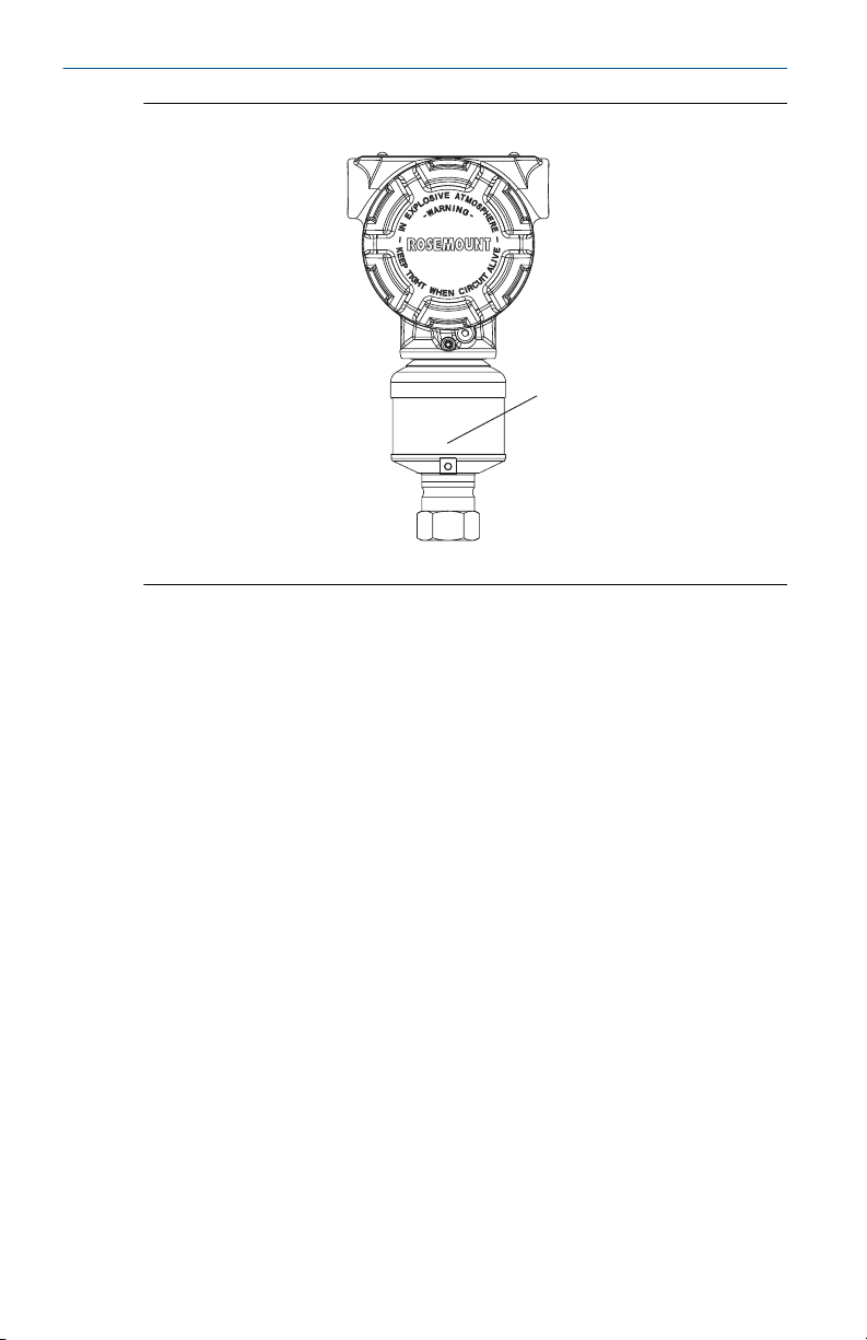
In-line gage transmitter orientation
The low side pressure port (atmospheric reference) on the in-line gage
transmitter is located under the sensor module neck label. (See Figure 2-6)
Keep the vent path free of any obstruction, including but not limited to
paint, dust, and lubrication by mounting the transmitter so that any
contaminants can drain away.
®
Page 10
A
Quick Start Guide April 2019
Figure 2-6: In-line Gage Transmitter
A. Low side pressure port (under neck label)
10 Rosemount 4088A MultiVariable Transmitter Quick Start Guide
Page 11

April 2019 Quick Start Guide
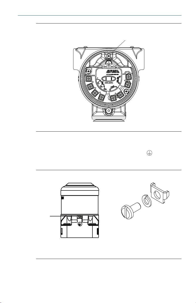
3 Consider housing rotation
To improve field access to wiring or to better view the optional LCD display:
Procedure
1. Loosen the housing rotation set screw.
2. Turn the housing up to 180° left or right of its original (as shipped)
position.
3. Re-tighten the housing rotation set screw.
Figure 3-1: Transmitter Housing Set Screw
A. LCD display
B. Housing rotation set screw (3/32-in.)
CAUTION
Do not rotate the housing more than 180° without first performing a
disassembly procedure. Over-rotation may sever the electrical
connection between the sensor module and the electronics.
3.1
Quick Start Guide 11
Rotate the LCD display
Transmitters ordered with the LCD display will be shipped with the display
installed.
In addition to housing rotation, the optional LCD display can be rotated in
90° increments by squeezing the two tabs, pulling out, rotating and
snapping back into place.
If LCD display pins are inadvertently removed from the electronics board,
carefully re-insert the pins before snapping the LCD display back into place.
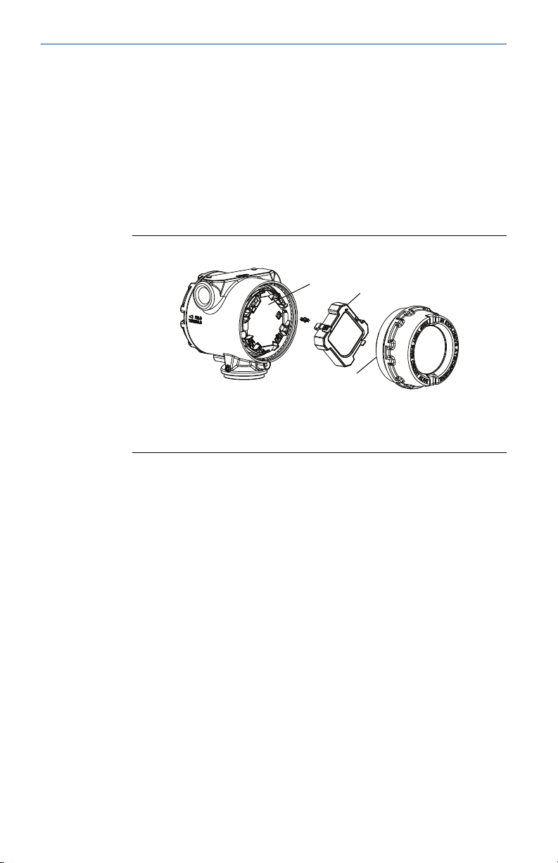
Use the following procedure and Figure 3-2 to install the LCD display:
Procedure
1. If the transmitter is installed in a loop, then secure the loop and
disconnect power.
Page 12
B
C
A
Quick Start Guide April 2019
2. Required: Remove the transmitter cover on the electronics board
side (opposite the field terminals side). Do not remove instrument
covers in explosive environments when circuit is live.
3. Engage the four-pin connector into the electronics board and snap
LCD display into place.
4. Required: In order to meet explosion-proof requirements, reinstall
the housing cover and tighten so the cover is fully seated with metal
to metal contact between the housing and cover. After the cover is
seated properly, replace the flathead screw located on the bottom of
the housing cover.
Figure 3-2: Optional LCD Display
A. Electronics board
B. LCD display
C. Display cover
12 Rosemount 4088A MultiVariable Transmitter Quick Start Guide
Page 13
A B
April 2019 Quick Start Guide
4 Set the switches
Procedure
1. If the transmitter is installed, secure the bus and remove power.
2. Required: Remove the transmitter cover opposite the field terminal
side. Do not remove the instrument covers in explosive
environments when the circuit is live.
3. Slide the Security and switches into the preferred position by using a
small screwdriver.
Note
The Security switch will need to be in the off position in order to make
any configuration changes.
4. Required: In order to meet explosion-proof requirements, reinstall
the housing cover and tighten so the cover is fully seated with metal
to metal contact between the housing and cover. After the cover is
seated properly, replace the flathead screw located on the bottom of
the housing cover.
Figure 4-1: Transmitter Switch Configuration
A. Security
B. AC Termination
Quick Start Guide 13
Page 14

Quick Start Guide April 2019
5 Wiring and power up
Use the following steps to wire the transmitter:
Procedure
1. Remove the cover on the field terminals side of the housing.
2. Set up based on optional process temperature input.
a) If the optional process temperature input is being utilized,
follow the procedure Install optional process temperature
input (Pt 100 RTD Sensor).
b) If there will not be an optional process temperature input,
plug and seal the unused conduit connection.
NOTICE
When the enclosed threaded plug is utilized in the conduit
opening, it must be installed with a minimum engagement of
five threads in order to comply with explosion-proof
requirements. For straight threads, a minimum of six threads
must be engaged. For tapered threads, install the plug
wrench-tight.
3. Connect the Rosemount 4088A to the RS-485 bus as shown in Figure
6-2.
a) Connect the A lead to the “A” terminal.
b) Connect the B lead to the “B” terminal.
4. Connect the positive lead from the power source to the “PWR +”
terminal, and the negative lead to the “PWR –” terminal (for power
requirements, reference ).
Note
The Rosemount 4088A uses RS-485 Modbus® with eight data bits,
one stop bit and no parity. The default baud rate is 9600.
Note
Twisted pair wiring is required for RS-485 bus wiring. Wiring runs
under 1000 ft (305 m) should be AWG 22 or larger. Wiring runs from
1000 to 4000 ft. (305 to 1219 m) should be AWG 20 or larger. Wiring
should not exceed AWG 16.
5. Ensure full contact with terminal block screw and washer. When
using a direct wiring method, wrap wire clockwise to ensure it is in
place when tightening the terminal block screw.
14 Rosemount 4088A MultiVariable Transmitter Quick Start Guide
Page 15
D
D
B
A
C
E
April 2019 Quick Start Guide
Note
The use of a pin or a ferrule wire terminal is not recommended as the
connection may be more susceptible to loosening over time or under
vibration.
6. Reinstall the housing cover and tighten so the cover is fully seated
with metal to metal contact between the housing and cover in order
to meet explosion-proof requirements.
Note
Installation of the transient protection terminal block does not
provide transient protection unless the transmitter housing is
properly grounded.
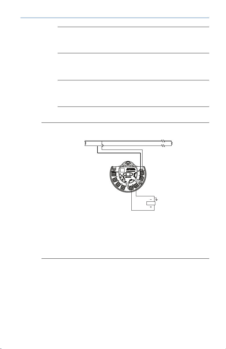
Example
Figure 5-1: Transmitter Wiring for RS-485 Bus
A. RS- 485 (A)
B. RS-485 (B)
C. RS-485 bus, twisted pair required
D. Bus Termination: AC Termination on Rosemount 4088 (see Set the
switches) or 120 Ω resistor
E. User-Provided Power Supply
5.1
Quick Start Guide 15
Grounding
Signal wire grounding
Do not run signal wiring in conduit or open trays with power wiring, or near
heavy electrical equipment. If shielded wiring is used, ground the shield of
the signal wiring at any one point on the signal loop. Device must be
properly grounded or earthed according to local electric codes.
Page 16

DP
A
D
F
B
C
E
Quick Start Guide April 2019
Figure 5-2: Signal Ground Wiring
A. Positive
B. Minimize distance
C. Trim shield and insulate
D. Insulate shield
E. Connect shield back to the power supply
F. Negative
Transmitter case
Always ground the transmitter case in accordance with national and local
electrical codes. The most effective transmitter case grounding method is a
direct connection to earth ground with minimal impedance (< 1 Ω ).
Methods for grounding the transmitter case include:
Internal ground connection
The internal ground connection screw is inside the terminal side of the
electronics housing. The screw is identified by a ground symbol ( ).
16 Rosemount 4088A MultiVariable Transmitter Quick Start Guide
Page 17
A
A
B
April 2019 Quick Start Guide
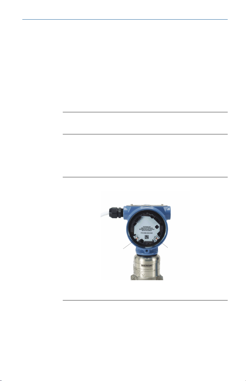
Figure 5-3: Internal Ground Connection
A. Ground lug
External ground connection
The external ground connection is on the outside of the sensor module
housing. The connection is identified by a ground symbol ( ). An external
ground assembly is included with the option codes shown in Table 5-1 or is
available as a spare part (03151-9060-0001).
Figure 5-4: External Ground Connection
A. External ground lug
B. External ground assembly (03151-9060-0001)
Quick Start Guide 17
Page 18

Quick Start Guide April 2019
Table 5-1: External Ground Screw Approval Option Codes
Option code Description
E1 ATEX Flameproof
I1 ATEX Intrinsic Safety
N1 ATEX Type n
ND ATEX Dust
K1 ATEX Flameproof, Intrinsic Safety, Type n, Dust (combination
E7 IECEx Flameproof, Dust Ignition-proof
N7 IECEx Type n
K7 IECEx Flameproof, Dust Ignition-proof, Intrinsic Safety, and
KA ATEX and CSA Explosion-proof, Intrinsically Safe, Division 2
KC FM and ATEX Explosion-proof, Intrinsically Safe, Division 2
T1 Transient terminal block
D4 External ground screw assembly
of E1, I1, N1, and ND)
Type n (combination of E7, I7, and N7)
(combination of E1, E6, I1, and I6)
(combination of E5, E1, I5, and I1)
Surges/transients
The transmitter will withstand electrical transients of the energy level usually
encountered in static discharges or induced switching transients. However,
high-energy transients, such as those induced in wiring from nearby
lightning strikes, can damage the transmitter.
Optional transient protection terminal block
The transient protection terminal block can be ordered as an installed option
(option code T1 in the transmitter model number) or as a spare part to
retrofit existing Rosemount 4088 MultiVariable Transmitters in the field. For
a complete listing of spare part numbers for transient protection terminal
blocks, refer to the Spare parts list section in the Rosemount 4088
MultiVariable Transmitter Reference Manual. A lightning bolt symbol on a
terminal block identifies it as having transient protection.
Note
Grounding the transmitter case using the threaded conduit connection may
not provide a sufficient ground. The transient protection terminal block
(option code T1) will not provide transient protection unless the transmitter
case is properly grounded. See Transmitter case to ground the transmitter
18 Rosemount 4088A MultiVariable Transmitter Quick Start Guide
Page 19

April 2019 Quick Start Guide
case. Do not run transient protection ground wire with signal wiring; the
ground wire may carry excessive current if a lightning strike occurs.
5.2 Install optional process temperature input (Pt 100 RTD Sensor)
Note
To meet ATEX/IECEx Flameproof certification, only ATEX/IECEx Flameproof
cables (temperature input code C30, C32, C33, or C34) may be used.
Procedure
1. Mount the Pt 100 RTD Sensor in the appropriate location.
Note
Use shielded 4- or 3-wire cable for the process temperature
connection.
2. Connect the RTD cable to the transmitter by inserting the cable wires
through the unused housing conduit and connect to the screws on
the transmitter terminal block. An appropriate cable gland should be
used to seal the conduit opening around the cable.
Note
If power is already connected to the Rosemount 4088, power should
be removed prior to connecting the RTD wires. This will allow the
Rosemount 4088 to detect the RTD type at startup. Once the RTD is
installed, reconnect power.
3. Connect the RTD cable shield wire to the ground lug in the housing.
Quick Start Guide 19
Page 20
A
Red
White
B
B
A
C
C
White
Red
Quick Start Guide April 2019
Figure 5-5: Transmitter RTD Wiring Connection
3-wire 4-wire
A. Ground Lug
B. Pt 100 RTD sensor
C. Connection head
20 Rosemount 4088A MultiVariable Transmitter Quick Start Guide
Page 21
A
B
C
D
OR
April 2019 Quick Start Guide
6 Verify device configuration
For Rosemount 4088A, use Rosemount Transmitter Interface Software with
the Rosemount 4088 DTM or a HART Field Communicator with the
Rosemount 4088 Device Descriptor to communicate with and verify
configuration of the transmitter.
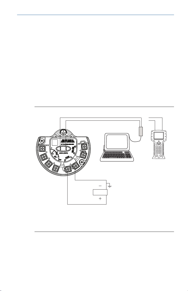
Figure 6-1 shows the wiring connections necessary to power a Rosemount
4088 MultiVariable Transmitter and enable communications with a PCbased software tool or handheld Field Communicator.
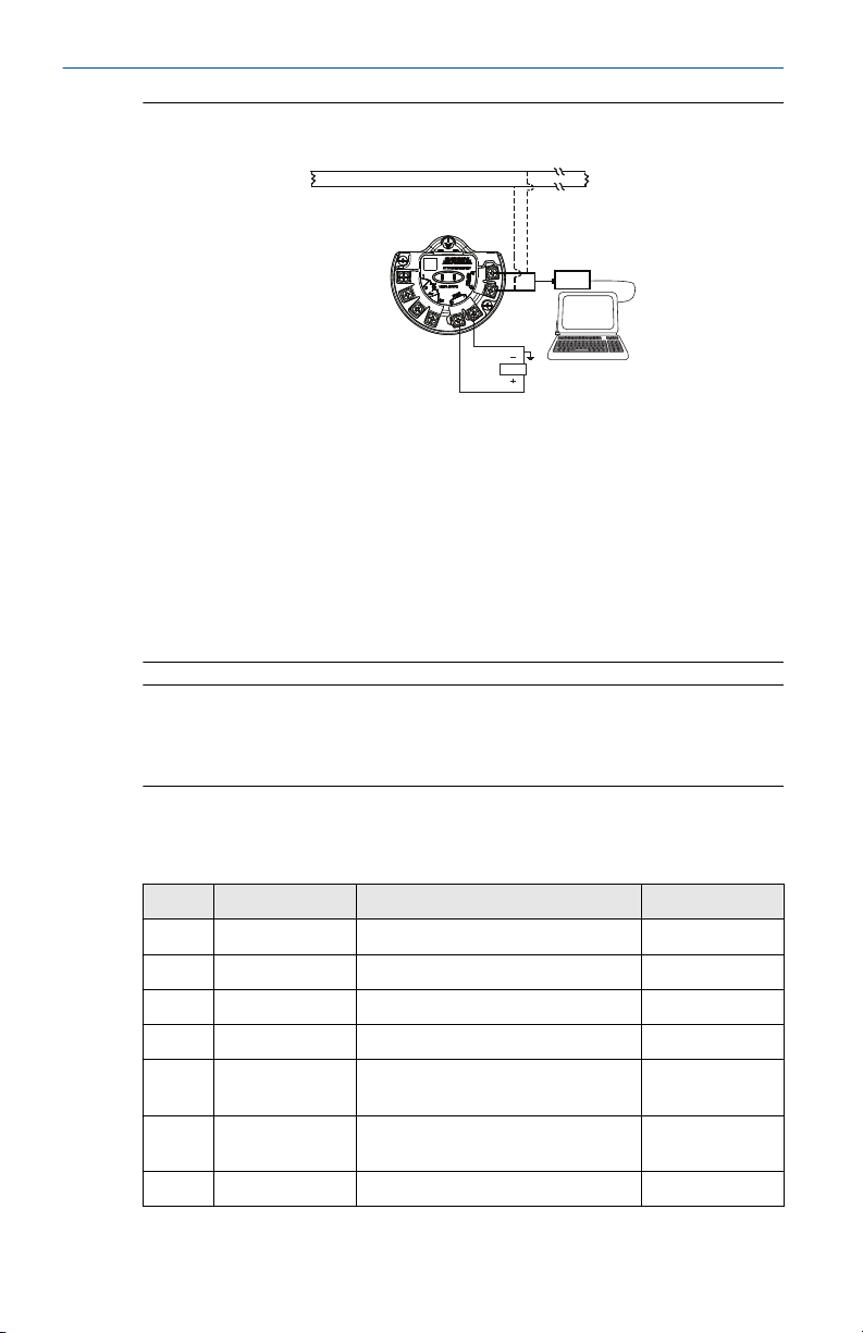
6.1 Transmitter wiring
It is not required to remove the Rosemount 4088 from the RS-485 network
when configuring over the local HART® port. The device should be taken out
of service or put in manual prior to performing any configuration changes.
Figure 6-1: Connecting a Personal Computer to a Transmitter
A. Rosemount transmitter interface software (RTIS)
B. HART modem
C. Field Communicator
D. User-provided power supply
The Rosemount 4088 may be configured with the Rosemount 3095FB
Configuration Software. When using this legacy tool, only functionality that
was available with the Rosemount 3095FB can be accessed. The device must
be removed from the Modbus network prior to communicating over the
RS-485 bus.
Quick Start Guide 21
Page 22
D
C
B
A
D
E
F
G
Quick Start Guide April 2019
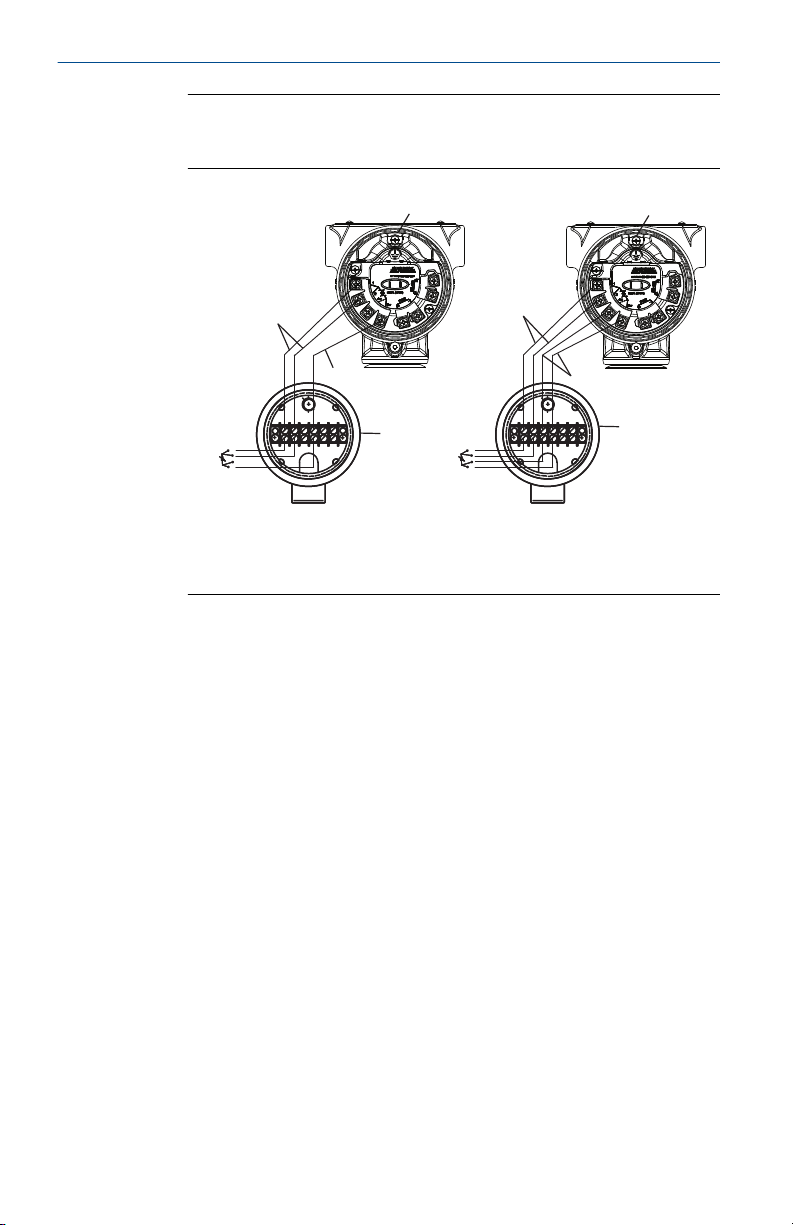
Figure 6-2: Transmitter Configuration via RS-485 Network Port
A. RS- 485 (A)
B. RS-485 (B)
C. RS-485 bus, twisted pair required
D. Bus Termination: AC termination on Rosemount 4088 (see Set the
switches) or 120 Ω resistor
E. User-Provided Power Supply
F. Rosemount 3095FB configuration software
G. RS 232/RS 485 converter
Note
Device configuration procedures are given for RTIS in the Rosemount 4088
MultiVariable Transmitter Reference Manual. This manual also includes a
detailed Modbus register map.
Table 6-1: Field Communication Fast Keys
A check (✓) indicates the basic configuration parameters. At a minimum, these
parameters should be verified as part of the configuration and startup procedure.
Category Function Sequence
✓ Device Available Measurements 1, 9, 4
Device Display 2, 2, 5
Device Sensor Module Temperature 2, 2, 4
Device Sensor Module Temperature Units 2, 2, 4, 3
Device Sensor Module Temperature Upper
Device Sensor Module Temperature Lower
✓ Device Device Address 2, 2, 6, 1, 1
Alert Limit
Alert Limit
22 Rosemount 4088A MultiVariable Transmitter Quick Start Guide
2, 2, 4, 4
2, 2, 4, 5
Page 23

April 2019 Quick Start Guide
Table 6-1: Field Communication Fast Keys (continued)
Category Function Sequence
Device Device Status 1, 1
Device Baud Rate 2, 2, 6, 1, 2
Device Turnaround Delay 2, 2, 6, 1, 3
Device Tag 2, 2, 7, 1, 1
Device Long Tag 2, 2, 7, 1, 2
Device Transmitter S/N 2, 2, 7, 1, 7
Device Security Switch 1, 9, 5, 1
DP Sensor DP 2, 2, 1
DP Sensor Calibration 3, 4, 1, 8
✓ DP Sensor DP Units 2, 2, 1, 3
✓ DP Sensor DP Damping 2, 2, 1, 4
DP Sensor Verification 3, 4, 1, 9
DP Sensor Upper Alert Limit 2, 2, 1, 6
DP Sensor Lower Alert Limit 2, 2, 1, 7
PT Sensor Sensor Matching 2, 2, 3, 8
PT Sensor PT 2, 2, 3
PT Sensor Calibration 3, 4, 3, 8
✓ PT Sensor PT Units 2, 2, 3, 3
✓ PT Sensor PT Damping 2, 2, 3, 4
✓ PT Sensor Sensor Type 2, 2, 3, 5
PT Sensor Verification 3, 4, 3, 9
PT Sensor Upper Alert Limit 2, 2, 3, 6, 1
PT Sensor Lower Alert Limit 2, 2, 3, 6, 2
✓ PT Sensor Temp Mode Setup 2, 2, 3, 7
SP Sensor AP 2, 2, 2, 7
✓ SP Sensor SP Units 2, 2, 2, 3
SP Sensor GP 2, 2, 2, 6
✓ SP Sensor SP Damping 2, 2, 2, 4
SP Sensor Calibration 3, 4, 2, 8
SP Sensor Verification 3, 4, 2, 9
Quick Start Guide 23
Page 24

Quick Start Guide April 2019
Table 6-1: Field Communication Fast Keys (continued)
Category Function Sequence
SP Sensor Upper Alert Limit 2, 2, 2, 6, 3
SP Sensor Lower Alert Limit 2, 2, 2, 6, 4
24 Rosemount 4088A MultiVariable Transmitter Quick Start Guide
Page 25

April 2019 Quick Start Guide
7 Trim the transmitter
Transmitters are shipped fully calibrated per request or by the factory
default of full scale.
Use RTIS with the Rosemount 4088 DTM or a HART Field Communicator
with the Rosemount 4088 Device Descriptor to communicate with and
perform maintenance on the Rosemount 4088 MultiVariable Transmitter.
7.1 Zero trim
A zero trim is a single-point adjustment used for compensating mounting
position and line pressure effects on static and differential pressure sensors.
When performing a zero trim, ensure that the equalizing valve is open and
all wet legs are filled to the correct level.
If zero offset is less than 5 percent of USL, follow the user interface software
instructions below to perform a zero trim on a Field Communicator.
7.1.1 Performing a zero trim using the Field Communicator
Procedure
1. Block, equalize, and vent the transmitter and connect the Field
Communicator (for more information on connecting the Field
Communicator, see The Connect to a personal computer section in
the Rosemount 4088 MultiTransmitter Reference Manual).
2. If the device is equipped with a static pressure sensor, trim the sensor
by inputting the following Fast Key sequence at the transmitter
menu:
Field Communicator
3. Follow the appropriate static pressure trim procedure.
4.
• Zero trim for gage pressure sensors
• Lower sensor trim for absolute pressure sensors
Note
It is possible to degrade the performance of the transmitter if the full
sensor trim is done improperly or with inaccurate calibration
equipment. Use a pressure input source that is at least three times
more accurate than the transmitter and allow the pressure input to
stabilize for ten seconds before entering any values.
5. Zero the differential pressure sensor by inputting the following Fast
Key sequence at the transmitter menu:
Quick Start Guide 25
3, 4, 2, 8
Page 26

Quick Start Guide April 2019
Field Communicator 3, 4, 1, 8, 5
6. Follow the zero DP trim procedure.
26 Rosemount 4088A MultiVariable Transmitter Quick Start Guide
Page 27

April 2019 Quick Start Guide
8 Product certifications
Rev 1.6
WARNING
Explosions could result in death or serious injury.
Installation of this transmitter in an explosive environment must be in
accordance with the appropriate local, national, and international standards,
codes, and practices. Review this document for any restrictions associated
with a safe installation.
• Before connecting a Field Communicator in an explosive atmosphere,
ensure the instruments in the loop are installed in accordance with
intrinsically safe or non-incendive field wiring practices.
• In an Explosion-proof/Flameproof installation, do not remove the
transmitter covers when power is applied to the unit.
WARNING
Conduit/cable entries
• Unless marked, the conduit/cable entries in the transmitter housing use
a 1/2–14 NPT thread form. Entries marked “M20” are M20 x 1.5 thread
form. On devices with multiple conduit entries, all entries will have the
same thread form. Only use plugs, adapters, glands, or conduit with a
compatible thread form when closing these entries.
• When installing in a hazardous location, use only appropriately listed or
Ex certified plugs, adapters, or glands in cable/conduit entries.
8.1
8.2
Quick Start Guide 27
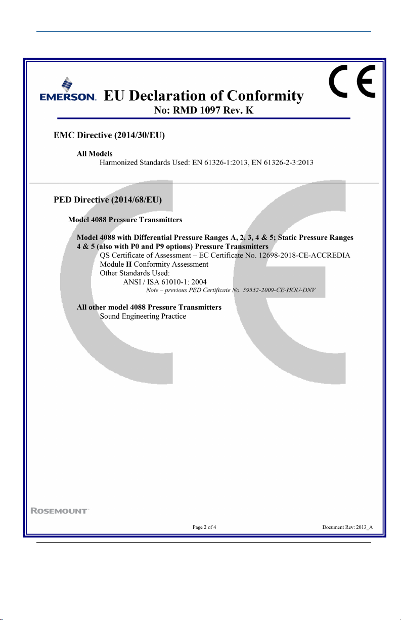
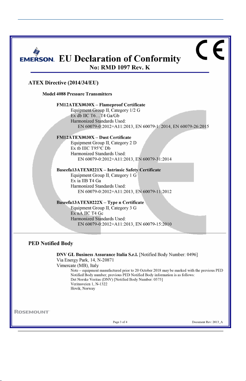
European Directive Information
A copy of the EU Declaration of Conformity can be found at the end of the
Quick Start Guide. The most recent revision of the EU Declaration of
Conformity can be found at Emerson.com/Rosemount .
Ordinary Location Certification
As standard, the transmitter has been examined and tested to determine
that the design meets the basic electrical, mechanical, and fire protection
requirements by a nationally recognized test laboratory (NRTL) as accredited
by the Federal Occupational Safety and Health Administration (OSHA).
Page 28

Quick Start Guide April 2019
8.3 Installing Equipment in North America
The US National Electrical Code® (NEC) and the Canadian Electrical Code
(CEC) permit the use of Division marked equipment in Zones and Zone
marked equipment in Divisions. The markings must be suitable for the area
classification, gas, and temperature class. This information is clearly defined
in the respective codes.
8.4 USA
E5 FM Explosionproof (XP), Dust-Ignitionproof(DIP)
Certificate
Standards
Markings
Special Conditions for Safe Use (X):
1. This device contains a thin wall diaphragm less than 1 mm thickness
2. Flameproof joints are not intended for repair.
3. Appropriate cable, glands, and plugs need to be suitable for a
FM17US0146X
FM Class 3600 - 2011, FM 3610 - 2005, FM Class 3615 - 2005,
FM Class 3616 2011, FM 3810 - 2005, ANSI/NEMA 250 - 1991,
ANSI/IEC 60529 - 2004, ANSI/ISA 60079-0:2013, ANSI/ISA
60079-1:2015, ANSI/ISA 60079-26:2017
XP Class I, Division 1, Groups B, C, D (Ta = –50 to 85 °C); DIP
Class II and Class III, Division 1, Groups E, F, G (Ta = –50 to 85
°C); Class I Zone 0/1 AEx db IIC T5 (Ta = –50 to 80 °C);
Enclosure Type 4X/IP66/IP68; Conduit seal not required for
division installations
that forms a boundary between Class 1, Zone 0 (process connection)
and Class 1, Zone 1 (all other parts of the equipment). The model
code and datasheet are to be consulted for details of the diaphragm
material. Installation, maintenance and use shall take into account
the environmental conditions to which the diaphragm will be
subjected. The manufacturer's instructions for installation and
maintenance shall be followed in detail to assure safety during its
expected lifetime.
temperature of 5 °C greater than the maximum specified
temperature for location where installed.
4. The applicable temperature class, ambient temperature range and
process temperature range of the equipment is T4 for –50 ≤ Ta ≤ 80
°C with T process = –50 to 120 °C.
5. Non-standard paint options (paint options other than Rosemount
Blue) may cause risk from electrostatic discharge. Avoid installation
that could cause electrostatic build-up on painted surfaces, and only
clean the painted surfaces with a damp cloth.
28 Rosemount 4088A MultiVariable Transmitter Quick Start Guide
Page 29

April 2019 Quick Start Guide
6. Display glass shall be positioned in such a way as to minimize the risk
of mechanical impact.
I5 FM Intrinsic Safety (IS) and Nonincendive (NI)
Certificate
Standards
Markings
Special Conditions for Safe Use (X):
1. The maximum permitted ambient temperature of the Rosemount
2. The enclosure may contain aluminum and is considered to present a
3. The Rosemount 4088 Transmitters fitted with transient protection
Note
Transmitters marked with NI CL 1, DIV 2 can be installed in Division 2
locations using general Division 2 wiring methods or Nonincendive Field
Wiring (NIFW). See Drawing 04088-1206.
FM17US0263X
FM Class 3600 - 2011, FM Class 3610 - 2010, FM Class 3611 2004, FM Class 3810 - 2005, ANSI/NEMA 250 - 1991, ANSI/ISA
60529 - 2004, ANSI/ISA 61010-1 - 2004
Intrinsic Safety Class I, Division 1, Groups C, D; Class II, Groups
E, F, G; Class III; Class I Zone 0 AEx ia IIB T4; Nonincendive Class
I, Division 2, Groups A, B, C, D; T4(–50 ≤ Ta ≤ 70 °C); when
connected per Rosemount drawing 04088-1206; Type 4X
4088 Pressure Transmitter is 70 °C. To avoid the effects of process
temperature and other thermal effects care shall be taken to ensure
the surrounding ambient and the ambient inside the transmitter
housing does not exceed 70 °C.
potential risk of ignition by impact or friction. Care must be taken
during installation and use to prevent impact or friction.
are not capable of withstanding the 500 V test. This must be taken
into account during installation.
8.5
Quick Start Guide 29
Canada
All CSA hazardous approved transmitters are dual seal certified per ANSI/ISA
12.27.01–2003.
E6 CSA Explosionproof, Dust-Ignitionproof, and Division 2
Certificate
Standards
2618446
CSA C22.2 No. 0-10, CSA C22.2 No. 25-1966, CSA C22.2 No.
30-M1986, CSA C22.2 No. 94-M91, CSA C22.2 No. 142M1987, CSA C22.2 No. 213-M1987, CSA C22.2 No.
60079-0:2011, CSA C22.2 No. 60079-11:2011, ANSI/ISA
12.27.01-2003
Page 30

Quick Start Guide April 2019
Markings
I6 CSA Intrinsically Safe
Certificate
Standards
Markings
8.6 Europe
E1 ATEX Flameproof
Certificate
Standards
Markings
Class I, Division 1, Groups B, C, D; Class II, Division 1, Groups E,
F, G; Class III; Class I, Division 2, Groups A, B, C, D; Temp Code
T5; seal not required; when installed per Rosemount Drawing
04088-1053; Type 4X
2618446
CSA C22.2 No. 0-10, CSA C22.2 No. 25-1966, CSA C22.2 No.
30-M1986, CSA C22.2 No. 94-M91, CSA C22.2 No. 142M1987, CSA C22.2 No. 157-92, CSA C22.2 No. 213-M1987,
CSA C22.2 No. 60079-0:2011, CSA C22.2 No. 60079-11:2011,
ANSI/ISA 12.27.01-2003
Class I, Division 1, Groups C, D, Temp Code T3C; Class I Zone 0
Ex ia IIB T4; when installed per Rosemount Drawing
04088-1207; Type 4X
FM12ATEX0030X
EN 60079-0:2012+A11:2013, EN 60079-1:2014, EN
60079-26:2015, EN 60529:1991+A1:2000
II 1/2 G Ex db IIC T6…T4 Ga/Gb, T4/T5(–50 ≤ Ta ≤ 80 °C), T6(–
50 ≤ Ta ≤ 65 °C)
Special Conditions for Safe Use (X):
1. This device contains a thin wall diaphragm less than 1 mm thickness
that forms a boundary between Category 1 (process connection) and
Category 2 (all other parts of the equipment). The model code and
datasheet are to be consulted for details of the diaphragm material.
Installation, maintenance and use shall take into account the
environmental conditions to which the diaphragm will be subjected.
The manufacturer's instructions for installation and maintenance
shall be followed in detail to assure safety during its expected
lifetime.
2. Flameproof joints are not intended for repair.
3. Appropriate cable, glands, and plugs need to be suitable for a
temperature of 5 °C greater than the maximum specified
temperature for location where installed.
4. The applicable temperature class, ambient temperature range and
process temperature range of the equipment is as follows:
30 Rosemount 4088A MultiVariable Transmitter Quick Start Guide
Page 31

April 2019 Quick Start Guide
• T4 for –50 ≤ Ta ≤ 80 °C with T process = –50 to 120 °C
• T5 for –50 ≤ Ta ≤ 80 °C with T process = –50 to 80 °C
• T6 for –50 ≤ Ta ≤ 65 °C with T process = –50 to 65 °C
5. Non-standard paint options (paint options other than Rosemount
Blue) may cause risk from Electrostatic discharge. Avoid installation
that could cause electrostatic build-up on painted surfaces, and only
clean the painted surfaces with a damp cloth.
6. Display glass shall be positioned in such a way as to minimize the risk
of mechanical impact.
I1 ATEX Flameproof
Certificate
Standards
Markings
Supply Modbus RTD
Voltage U
Current I
Power P
Capacitance C
Inductance L
i
i
i
Baseefa13ATEX0221X
EN 60079-0:2012, EN 60079-11:2012
Ex II 1 G Ex ia IIB T4 Ga (–60 ≤ Ta ≤ +70 °C)
22 V 9 V 15.51 V
147 mA 26 mA 20.89 mA
1 W 1 W 80.94 mW
0 0 0
i
i
0 0 0
Special Conditions for Safe Use (X):
1. The Rosemount 4088 MV Transmitters fitted with transient
protection are not capable of withstanding the 500 V test as defined
in Clause 6.3.13 of EN 60079-11:2012. This must be taken into
account during installation.
2. The Rosemount 4088 MV enclosure may be made of aluminum alloy
and given a protective polyurethane paint finish; however, care
should be taken to protect it from impact or abrasion if located in a
Zone 0 area.
ND ATEX Dust
Certificate
Standards
FM12ATEX0030X
EN 60079-0:2012+A11:2013, EN 60079-31:2014, EN
60529:1991+A1:2000
Markings
Quick Start Guide 31
Ex II 2 D Ex tb IIIC T95 °C, Ta= –20 to 85 °C Db
Page 32

Quick Start Guide April 2019
Special Conditions for Safe Use (X):
1. Cable entries must be used which maintain the ingress protection of
the enclosure to at least IP66/68.
2. Unused cable entries must be filled with suitable blanking plugs
which maintain the ingress protection of the enclosure to at least
IP66/68.
3. Cable entries and blanking plugs must be suitable for the ambient
range of the apparatus and capable of withstanding a 7J impact test.
4. Non-standard paint options (paint options other than Rosemount
Blue) may cause risk from Electrostatic discharge. Avoid installation
that could cause electrostatic build-up on painted surfaces, and only
clean the painted surfaces with a damp cloth.
5. Display glass shall be positioned in such a way as to minimize the risk
of mechanical impact.
N1 ATEX Type n
8.7
Certificate
Standards
Markings
Special Condition for Safe Use (X):
The Rosemount 4088 MV Transmitters fitted with transient protection are
not capable of withstanding the 500 V test as defined in Clause 6.5.1 of EN
60079-15:2010. This must be taken into account during installation.
B aseefa13ATEX0222X
EN 60079-0:2012, EN 60079-15: 2010
Ex II 3 G Ex nA IIC T5 Gc (–40 ≤ Ta ≤ 70 °C)
International
E7 IECEx Flameproof
Certificate
Standards
Markings
Special Conditions for Safe Use (X):
1. This device contains a thin wall diaphragm less than 1 mm thickness
IECEx FMG 13.0024X
IEC 60079-0:2011, IEC 60079-1: 2014, IEC 60079-26: 2014
Ex db IIC T6…T4 Ga/Gb, T4/T5(–50 ≤ Ta ≤ 80 °C), T6(–50 ≤ Ta ≤
65 °C)
that forms a boundary between EPL Ga (process connection) and EPL
Gb (all other parts of the equipment). The model code and datasheet
are to be consulted for details of the diaphragm material.
Installation, maintenance and use shall take into account the
environmental conditions to which the diaphragm will be subjected.
32 Rosemount 4088A MultiVariable Transmitter Quick Start Guide
Page 33

April 2019 Quick Start Guide
The manufacturer's instructions for installation and maintenance
shall be followed in detail to assure safety during its expected
lifetime.
2. Flameproof joints are not intended for repair.
3. Appropriate cable, glands, and plugs need to be suitable for a
temperature of 5 °C greater than the maximum specified
temperature for location where installed.
4. The applicable temperature class, ambient temperature range and
process temperature range of the equipment is as follows:
• T4 for –50 ≤ Ta ≤ 80 °C with T process = –50 to 120 °C
• T5 for –50 ≤ Ta ≤ 80 °C with T process = –50 to 80 °C
• T6 for –50 ≤ Ta ≤ 65 °C with T process = –50 to 65 °C
5. Non-standard paint options (paint options other than Rosemount
Blue) may cause risk from electrostatic discharge. Avoid installation
that could cause electrostatic build-up on painted surfaces, and only
clean the painted surfaces with a damp cloth.
6. Display glass shall be positioned in such a way as to minimize the risk
of mechanical impact.
I7 IECEx Intrinsic Safety
Certificate
Standards
Markings
Supply Modbus RTD
Voltage U
Current I
Power P
Capacitance C
Inductance L
i
i
i
IECEx BAS 13.0110X
IEC 60079-0:2011, IEC 60079-11:2011
Ex ia IIB T4 Ga (–60 ≤ Ta ≤ +70 °C)
22 V 9 V 15.51 V
147 mA 26 mA 20.89 mA
1 W 1 W 80.94 mW
0 0 0
i
i
0 0 0
Special Conditions for Safe Use (X):
1. The Rosemount 4088 MV Transmitters fitted with transient
protection are not capable of withstanding the 500V test as defined
in Clause 6.3.13 of IEC 60079-11:2012. This must be taken into
account during installation.
Quick Start Guide 33
Page 34

Quick Start Guide April 2019
2. The Rosemount 4088 MV enclosure may be made of aluminum alloy
and given a protective polyurethane paint finish; however, care
should be taken to protect it from impact or abrasion if located in a
Zone 0 area.
NK IECEx Dust
Certificate
Standards
Markings
Special Conditions for Safe Use (X):
1. Cable entries must be used which maintain the ingress protection of
the enclosure to at least IP66/68.
2. Unused cable entries must be filled with suitable blanking plugs
which maintain the ingress protection of the enclosure to at least
IP66/68.
3. Cable entries and blanking plugs must be suitable for the ambient
range of the apparatus and capable of withstanding a 7J impact test.
4. Non-standard paint options (paint options other than Rosemount
Blue) may cause risk from Electrostatic discharge. Avoid installation
that could cause electrostatic build-up on painted surfaces, and only
clean the painted surfaces with a damp cloth.
5. Display glass shall be positioned in such a way as to minimize the risk
of mechanical impact.
N7 IECEx Type n
Certificate
Standards
Markings
IECEx FMG 13.0024X
IEC 60079-0:2011, IEC 60079-31:2013
Ex tb IIIC T95 °C, Ta = –20 to 85 °C, Db
IECEx BAS 13.0111X
IEC 60079-0:2011, IEC 60079-15: 2010
Ex nA IIC T5 Gc (–40 ≤ Ta ≤ +70 °C)
Special Conditions for Safe Use (X):
1. The Rosemount 4088 MV Transmitters fitted with transient
protection are not capable of withstanding the 500 V test as defined
in Clause 6.5.1 of IEC 60079-15:2010. This must be taken into
account during installation.
8.8
34 Rosemount 4088A MultiVariable Transmitter Quick Start Guide
Brazil
E2 INMETRO Flameproof
Certificate
UL-BR 15.0531X
Page 35

April 2019 Quick Start Guide
Standards
ABNT NBR IEC60079-0:2013, ABNT NBR IEC60079-1:2016,
ABNT NBR IEC60079-26:2016
Markings
Ex db IIC T6…T4 Ga/Gb, T6(–50 ≤ Ta ≤ +65 °C), T5/T4(–50 ≤ T
≤ +80 °C)
Special Conditions for Safe Use (X):
1. This device contains a thin wall diaphragm. Installation, maintenance
and use shall take into account the environmental conditions to
which the diaphragm will be subjected. The manufacturer's
instructions for installation and maintenance shall be followed in
detail to assure safety during its expected lifetime.
2. Flameproof joints are not intended for repair.
3. Appropriate cable, glands, and plugs need to be suitable for a
temperature of 5 °C greater than the maximum specified
temperature for the location where it is installed.
4. Non-standard paint options (paint options other than Rosemount
Blue) may cause risk from electrostatic discharge. Avoid installation
that could cause electrostatic build-up on painted surfaces, and only
clean the painted surfaces with a damp cloth.
5. Display glass should be positioned in such a way as to minimize the
risk of mechanical impact.
6. The applicable temperature class, ambient temperature range and
process temperature range of the equipment is as follows:
• T4 for –50 ≤ Ta ≤ 80 °C with T process = –50 to 120 °C
• T5 for –50 ≤ Ta ≤ 80 °C with T process = –50 to 80 °C
• T6 for –50 ≤ Ta ≤ 65 °C with T process = –50 to 65 °C
a
I2 INMETRO Intrinsic Safety
Certificate
Standards
UL-BR 15.0720X
ABNT NBR IEC60079-0:2008 + Errata 1:2011, ABNT NBR
IEC60079-11:2009
Markings
Supply Modbus RTD
Voltage U
Current I
Power P
Quick Start Guide 35
Ex ia IIB T4 Ga, T4(–60 ≤ Ta ≤ +70 °C)
i
i
i
22 V 9 V 15.51 V
147 mA 26 mA 20.89 mA
1 W 1 W 80.94 mW
Page 36

Quick Start Guide April 2019
Supply Modbus RTD
Capacitance C
Inductance L
i
0 0 0
i
0 0 0
Special Conditions for Safe Use (X):
1. If the equipment is fitted with an optional 90V transient suppressor,
it is not capable of withstanding the 500 V insulation test required by
ABNT NBR IRC 60079-11. This must be taken into account when
installing the equipment.
2. The enclosure may be made of aluminum alloy and given a protective
polyurethane paint finish; however, care should be taken to protect it
from impact or abrasion in zones that require EPL Ga.
8.9 Technical Regulations Customs Union (EAC)
EM EAC Flameproof
8.10
Certificate
Markings
RU C-US.Mю62.B.02349
Ga/Gb Ex d IIC T6…T4 X, T5/T4(–50 ≤ Ta ≤ +80 °C), T6(–50 ≤ T
≤ +65 °C)
Special Conditions for Safe Use (X):
1. See certificate for special conditions.
IM EAC Intrinsically Safe
Certificate
Markings
RU C-US.Mю62.B.02349
0Ex ia IIB T4 Ga X, T4(–60 ≤ Ta ≤ +70 °C)
Special Conditions for Safe Use (X):
1. See certificate for special conditions.
Combinations
K1
K2
K5
K6
K7
KA
Combination of E1, I1, N1, and ND
Combination of E2 and I2
Combination of E5 and I5
Combination of E6 and I6
Combination of E7, I7, N7, and NK
Combination of E1, I1, E6, and I6
a
36 Rosemount 4088A MultiVariable Transmitter Quick Start Guide
Page 37

April 2019 Quick Start Guide
KB
KC
KD
KM
Combination of E5, I5, E6, and I6
Combination of E1, I1, E5, and I5
Combination of E1, I1, E5, I5, E6, and I6
Combination of EM and IM
Quick Start Guide 37
Page 38

Quick Start Guide April 2019
8.11 EU Declaration of Conformity
38 Rosemount 4088A MultiVariable Transmitter Quick Start Guide
Page 39
April 2019 Quick Start Guide
Quick Start Guide 39
Page 40
Quick Start Guide April 2019
40 Rosemount 4088A MultiVariable Transmitter Quick Start Guide
Page 41

April 2019 Quick Start Guide
Quick Start Guide 41
Page 42

Quick Start Guide April 2019
42 Rosemount 4088A MultiVariable Transmitter Quick Start Guide
Page 43

April 2019 Quick Start Guide
Quick Start Guide 43
Page 44

*00825-0100-4088*
00825-0100-4088, Rev. CA
Quick Start Guide
April 2019
Global Headquarters
Emerson Automation Solutions
6021 Innovation Blvd.
Shakopee, MN 55379, USA
+1 800 999 9307 or +1 952 906 8888
+1 952 949 7001
RFQ.RMD-RCC@Emerson.com
Latin America Regional Office
Emerson Automation Solutions
1300 Concord Terrace, Suite 400
Sunrise, FL 33323, USA
+1 954 846 5030
+1 954 846 5121
RFQ.RMD-RCC@Emerson.com
Asia Pacific Regional Office
Emerson Automation Solutions
1 Pandan Crescent
Singapore 128461
+65 6777 8211
+65 6777 0947
Enquiries@AP.Emerson.com
North America Regional Office
Emerson Automation Solutions
8200 Market Blvd.
Chanhassen, MN 55317, USA
+1 800 999 9307 or +1 952 906 8888
+1 952 949 7001
RMT-NA.RCCRF@Emerson.com
Europe Regional Office
Emerson Automation Solutions Europe
GmbH
Neuhofstrasse 19a P.O. Box 1046
CH 6340 Baar
Switzerland
+41 (0) 41 768 6111
+41 (0) 41 768 6300
RFQ.RMD-RCC@Emerson.com
Middle East and Africa Regional Office
Emerson Automation Solutions
Emerson FZE P.O. Box 17033
Jebel Ali Free Zone - South 2
Dubai, United Arab Emirates
+971 4 8118100
+971 4 8865465
RFQ.RMTMEA@Emerson.com
Linkedin.com/company/Emerson-
Automation-Solutions
Twitter.com/Rosemount_News
Facebook.com/Rosemount
Youtube.com/user/
RosemountMeasurement
Google.com/+RosemountMeasurement
©
2019 Emerson. All rights reserved.
Emerson Terms and Conditions of Sale are
available upon request. The Emerson logo is a
trademark and service mark of Emerson Electric
Co. Rosemount is mark of one of the Emerson
family of companies. All other marks are the
property of their respective owners.
 Loading...