

Page 1

Model 4081C
Remote Controlled FOUNDATION
™
Fieldbus
Two-Wire Conductivity Transmitter
Instruction Manual
PN 51-4081C/rev.C
June 2002
Page 2

ESSENTIAL INSTRUCTIONS
READ THIS PAGE BEFORE PROCEEDING!
Rosemount Analytical designs, manufactures, and tests its products to meet
many national and international standards. Because these instruments are
sophisticated technical products, you must properly install, use, and maintain
them to ensure they continue to operate within their normal specifications. The
following instructions must be adhered to and integrated into your safety
program when installing, using, and maintaining Rosemount Analytical
products. Failure to follow the proper instructions may cause any one of the
following situations to occur: Loss of life; personal injury; property damage;
damage to this instrument; and warranty invalidation.
• Read all instructions prior to installing, operating, and servicing the product.
If this Instruction Manual is not the correct manual, telephone 1-800-6547768 and the requested manual will be provided. Save this Instruction
Manual for future reference.
• If you do not understand any of the instructions, contact your Rosemount
representative for clarification.
• Follow all warnings, cautions, and instructions marked on and supplied with
the product.
• Inform and educate your personnel in the proper installation, operation, and
maintenance of the product.
• Install your equipment as specified in the Installation Instructions of the
appropriate Instruction Manual and per applicable local and national codes.
Connect all products to the proper electrical and pressure sources.
• To ensure proper performance, use qualified personnel to install, operate,
update, program, and maintain the product.
• When replacement parts are required, ensure that qualified people use
replacement parts specified by Rosemount. Unauthorized parts and
procedures can affect the product’s performance and place the safe
operation of your process at risk. Look alike substitutions may result in fire,
electrical hazards, or improper operation.
• Ensure that all equipment doors are closed and protective covers are in
place, except when maintenance is being performed by qualified persons, to
prevent electrical shock and personal injury.
Emerson Process Management
Rosemount Analytical Inc.
2400 Barranca Parkway
Irvine, CA 92606 USA
Tel: (949) 757-8500
Fax: (949) 474-7250
http://www.RAuniloc.com
© Rosemount Analytical Inc. 2001
Page 3

TABLE OF CONTENTS
Section Title Page
1.0 INSTALLATION................................................................................................................. 1-1
1.1 Overview .................................................................................................................. 1-1
1.2 Mechanical Installation............................................................................................. 1-2
1.3 Electrical Installation ................................................................................................ 1-4
2.0 OPERATION OVERVIEW ................................................................................................. 2-1
2.1 General .................................................................................................................... 2-1
2.2 Display ..................................................................................................................... 2-1
2.3 Infrared Remote Control (IRC)................................................................................. 2-2
2.4 Diagnostic Messages............................................................................................... 2-2
2.5 Menu Program Tree................................................................................................. 2-3
3.0 FACTORY PROGRAMMED SETTINGS ........................................................................... 3-1
4.0 TRANSMITTER PROGRAM SET-UP ............................................................................... 4-1
4.1 Program Menu ......................................................................................................... 4-1
4.2 Temperature Parameters ......................................................................................... 4-2
4.3 Display Units ............................................................................................................ 4-3
5.0 START-UP AND CALIBRATION....................................................................................... 5-1
5.1 Accessing The Calibrate Menu ................................................................................ 5-1
5.2 Calibrate Menu ........................................................................................................ 5-2
5.3 Calibrate Menu (Contacting) .................................................................................... 5-3
5.4 Branch Calibration Initial Start-Up............................................................................ 5-4
5.5 Calibrate Menu (Low Conductivity/Resistivity)......................................................... 5-5
5.6 On-line Calibration ................................................................................................... 5-6
6.0 DIAGNOSIS AND TROUBLESHOOTING ........................................................................ 6-1
6.1 Overview .................................................................................................................. 6-1
6.2 Fault Conditions ....................................................................................................... 6-3
6.3 Diagnostic Messages............................................................................................... 6-4
6.4 Quick Troubleshooting Guide................................................................................... 6-5
6.5 Systematic Troubleshooting..................................................................................... 6-6
6.6 RTD Resistance Values ........................................................................................... 6-7
7.0 MAINTENANCE ................................................................................................................ 7-1
7.1 Overview .................................................................................................................. 7-1
7.2 Preventative Maintenance ....................................................................................... 7-1
7.3 Corrective Maintenance ........................................................................................... 7-1
8.0 PRODUCT DATA............................................................................................................... 8-1
8.1 Features................................................................................................................... 8-1
8.2 Specifications........................................................................................................... 8-2
8.3 Transmitter Display .................................................................................................. 8-3
8.4 Infrared Remote Control Functions.......................................................................... 8-3
8.5 Ordering Information ................................................................................................ 8-4
9.0 OPERATION WITH REMOTE CONTROLLER ................................................................. 9-1
10.0 RETURN OF MATERIALS ................................................................................................ 10-1
i
MODELS 4081C TABLE OF CONTENTS
MODEL 4081C
MICROPROCESSOR ANALYZERS
Page 4

ii
LIST OF FIGURES
Figure No. Title Page
1-1 Exploded Drawing of Circuit Board Stack . . . . . . . . . . . . . . . . . . . . . . . . . . . . . . . . . 1-1
1-2 Dimensional Information - Model 4081C . . . . . . . . . . . . . . . . . . . . . . . . . . . . . . . . . . 1-2
1-3 Mounting Information - Model 4081C . . . . . . . . . . . . . . . . . . . . . . . . . . . . . . . . . . . . 1-3
1-4 Contacting Conductivity Sensor Wiring to Model 4081C Transmitter . . . . . . . . . . . . 1-6
1-5 Sensor Wiring with Pre-existing Conductivity Sensors . . . . . . . . . . . . . . . . . . . . . . . 1-7
1-6 Model 4081C Terminal Blocks . . . . . . . . . . . . . . . . . . . . . . . . . . . . . . . . . . . . . . . . . . 1-8
1-7 Typical Fieldbus Network Electrical Wiring Configuration . . . . . . . . . . . . . . . . . . . . . 1-8
1-8 FM Explosion Proof Installation . . . . . . . . . . . . . . . . . . . . . . . . . . . . . . . . . . . . . . . . . 1-9
1-9 CSA Intrinsically Safe Installation . . . . . . . . . . . . . . . . . . . . . . . . . . . . . . . . . . . . . . . 1-11
1-10 FMRC Intrinsically Safe Installation . . . . . . . . . . . . . . . . . . . . . . . . . . . . . . . . . . . . . 1-13
2-1 Process Display Screen . . . . . . . . . . . . . . . . . . . . . . . . . . . . . . . . . . . . . . . . . . . . . . 2-1
2-2 Program Mode Display Areas . . . . . . . . . . . . . . . . . . . . . . . . . . . . . . . . . . . . . . . . . . 2-1
2-3 Infrared Remote Control . . . . . . . . . . . . . . . . . . . . . . . . . . . . . . . . . . . . . . . . . . . . . . 2-2
2-4 Menu Tree . . . . . . . . . . . . . . . . . . . . . . . . . . . . . . . . . . . . . . . . . . . . . . . . . . . . . . . . . 2-3
4-1 Program Menu and Menu Segments . . . . . . . . . . . . . . . . . . . . . . . . . . . . . . . . . . . . 4-1
4-2 RTD Sensor Connections . . . . . . . . . . . . . . . . . . . . . . . . . . . . . . . . . . . . . . . . . . . . . 4-2
4-3 Security Code Prompt . . . . . . . . . . . . . . . . . . . . . . . . . . . . . . . . . . . . . . . . . . . . . . . . 4-4
5-1 Calibration Menu Segments . . . . . . . . . . . . . . . . . . . . . . . . . . . . . . . . . . . . . . . . . . . 5-1
6-1 Diagnose Menu Segments . . . . . . . . . . . . . . . . . . . . . . . . . . . . . . . . . . . . . . . . . . . . 6-1
6-2 Diagnose Values . . . . . . . . . . . . . . . . . . . . . . . . . . . . . . . . . . . . . . . . . . . . . . . . . . . . 6-2
6-3 Disabling Fault Annunciation . . . . . . . . . . . . . . . . . . . . . . . . . . . . . . . . . . . . . . . . . . . 6-3
6-4 Non-disabling Warning Annunciation . . . . . . . . . . . . . . . . . . . . . . . . . . . . . . . . . . . . 6-3
6-5 Troubleshooting Flow Chart . . . . . . . . . . . . . . . . . . . . . . . . . . . . . . . . . . . . . . . . . . . 6-6
7-1 Hold Annunciation . . . . . . . . . . . . . . . . . . . . . . . . . . . . . . . . . . . . . . . . . . . . . . . . . . . 7-1
7-2 Exploded View of Model 4081C Transmitter . . . . . . . . . . . . . . . . . . . . . . . . . . . . . . . 7-2
8-1 Transmitter Display . . . . . . . . . . . . . . . . . . . . . . . . . . . . . . . . . . . . . . . . . . . . . . . . . . 8-3
8-2 Infrared Remote Control . . . . . . . . . . . . . . . . . . . . . . . . . . . . . . . . . . . . . . . . . . . . . . 8-3
8-3 Functional Block Diagram for Model 4081C Transmitter with F
OUNDATION Fieldbus . 8-3
9-1 Functional Block Diagram for Model 4081C Transmitter with FOUNDATION Fieldbus . 9-1
LIST OF TABLES
Table No. Title Page
1-1 Measurement Range . . . . . . . . . . . . . . . . . . . . . . . . . . . . . . . . . . . . . . . . . . . . . . . . . 1-4
1-2 Transmitter Range Limits (Ultra Pure) . . . . . . . . . . . . . . . . . . . . . . . . . . . . . . . . . . . . 1-4
1-3 Transmitter Range Limits (Resistivity) . . . . . . . . . . . . . . . . . . . . . . . . . . . . . . . . . . . . 1-5
1-4 Transmitter Range Limits (Conductivity) . . . . . . . . . . . . . . . . . . . . . . . . . . . . . . . . . . 1-5
3-1 Program Variables with Factory Settings . . . . . . . . . . . . . . . . . . . . . . . . . . . . . . . . . 3-1
4-1 Transmitter Settings . . . . . . . . . . . . . . . . . . . . . . . . . . . . . . . . . . . . . . . . . . . . . . . . . 4-3
4-2 Program Menu Mnemonics . . . . . . . . . . . . . . . . . . . . . . . . . . . . . . . . . . . . . . . . . . . . 4-4
5-1 Calibrate Menu Mnemonics . . . . . . . . . . . . . . . . . . . . . . . . . . . . . . . . . . . . . . . . . . . 5-6
6-1 Diagnostics Variables Mnemonics . . . . . . . . . . . . . . . . . . . . . . . . . . . . . . . . . . . . . . 6-2
6-2 Diagnostic Fault Messages . . . . . . . . . . . . . . . . . . . . . . . . . . . . . . . . . . . . . . . . . . . . 6-4
6-3 Quick Troubleshooting Guide . . . . . . . . . . . . . . . . . . . . . . . . . . . . . . . . . . . . . . . . . . 6-5
6-4 RTD Resistance Values . . . . . . . . . . . . . . . . . . . . . . . . . . . . . . . . . . . . . . . . . . . . . . 6-7
6-5 Conductivity Determination . . . . . . . . . . . . . . . . . . . . . . . . . . . . . . . . . . . . . . . . . . . . 6-7
7-1 Replacement Parts for Model 4081C Transmitter . . . . . . . . . . . . . . . . . . . . . . . . . . . 7-2
LIST OF APPENDICES
Section Title Page
A Glossary . . . . . . . . . . . . . . . . . . . . . . . . . . . . . . . . . . . . . . . . . . . . . . . . . . . . . . . . . . A-1
B 4081C Resource and Transducer Block Parameters. . . . . . . . . . . . . . . . . . . . . . . . . B-1
MODELS 4081C TABLE OF CONTENTS
Page 5
MODELS 4081C SECTION 1.0
INSTALLATION
SECTION 1.0
INSTALLATION
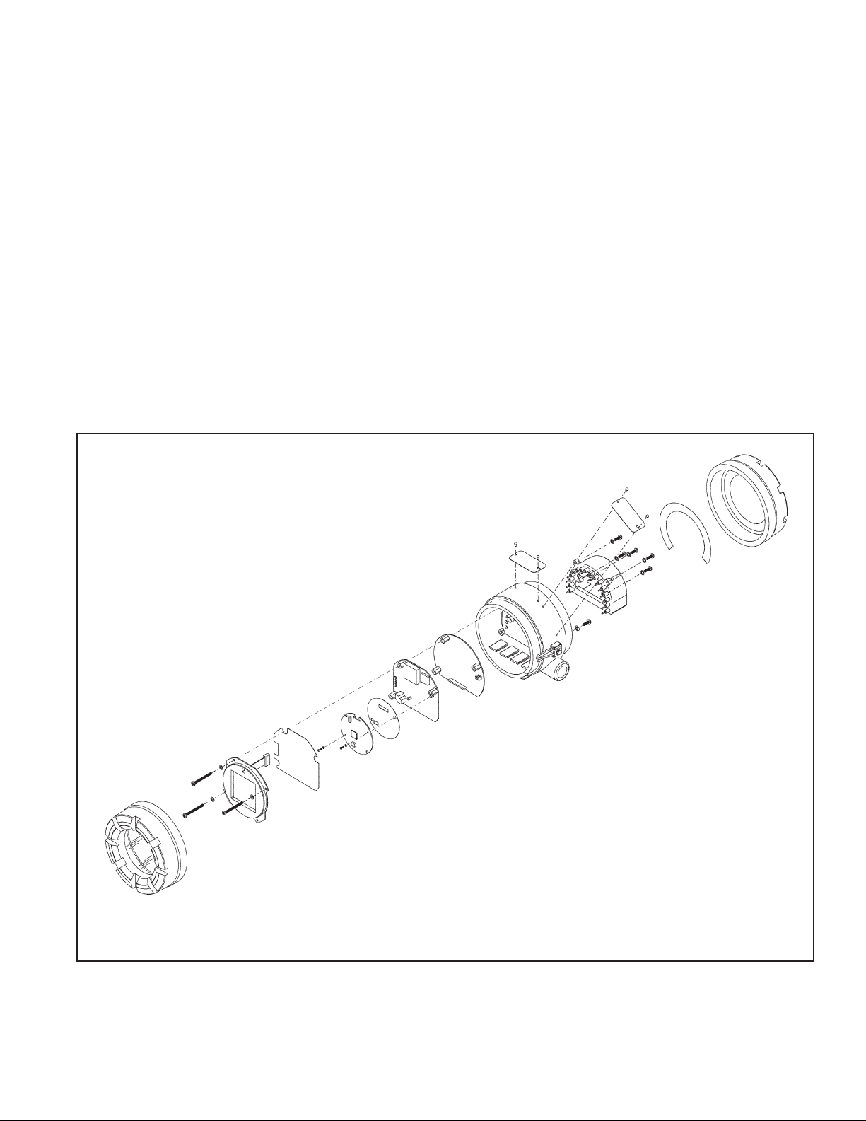
FIGURE 1-1. Model 4081C Transmitter - Exploded Drawing of Circuit Board Stack
1.1 OVERVIEW
This conductivity transmitter has been designed for
easy installation and shipment. The purpose of this
section is to provide information on the electrical configurations and the physical mountings available. Prior
to discarding the packing case:
If it is damaged, the transmitter may have also
sustained damage. Contact the carrier at once.
Remove all items shown on the packing list and
note any exceptions.
1-1
The Model 4081C conductivity transmitter is designed
to make accurate measurements while the sensor is
submersed in the process stream. Measurements can
also be tailored to high temperature and/or high pressure streams. The specific ranges covered are controlled by both hardware and software.
Page 6
1-2
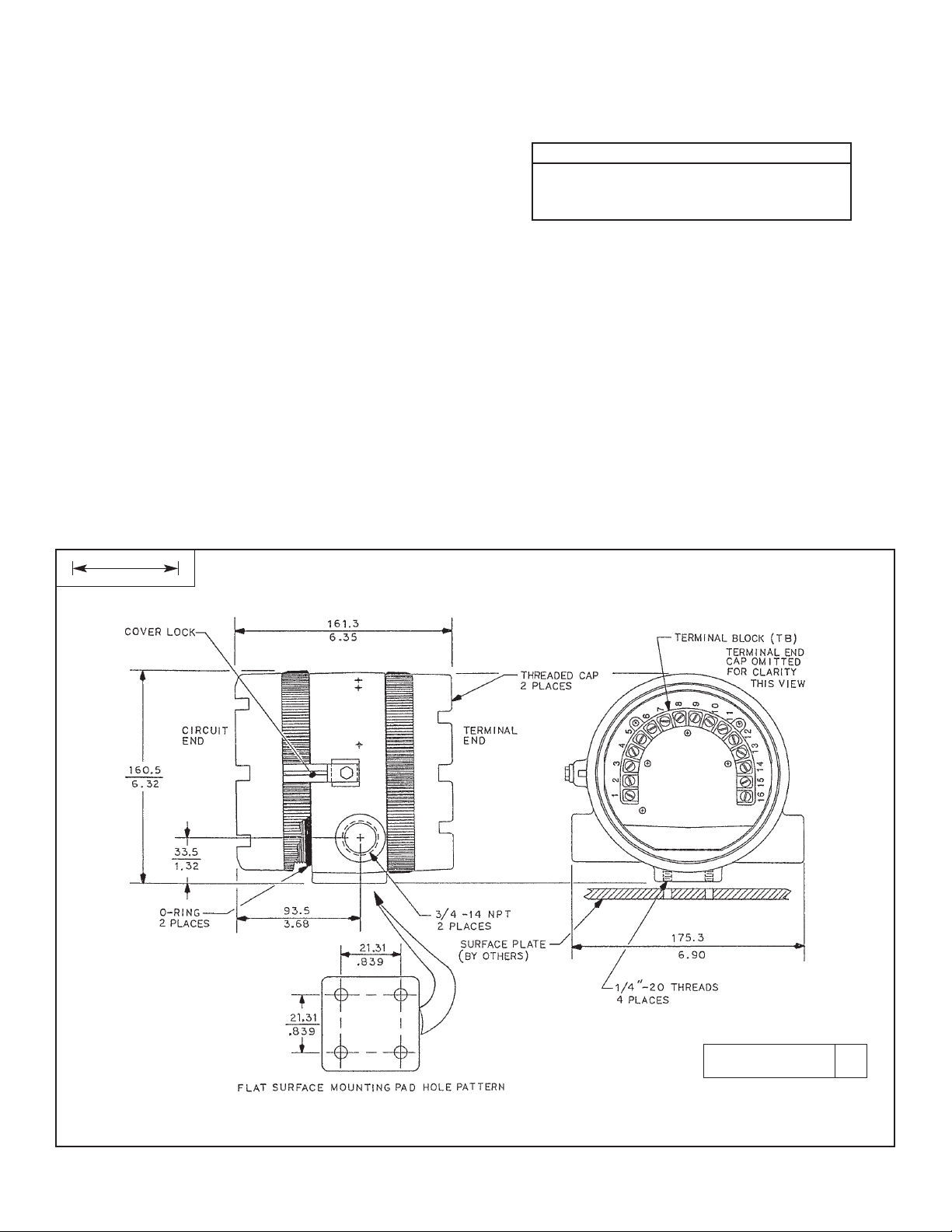
FIGURE 1-2. Dimensional Information – Model 4081C
DWG. NO. REV.
44081C01 A
MILLIMETER
INCH
MODELS 4081C SECTION 1.0
INSTALLATION
1.2 MECHANICAL INSTALLATION
The Model 4081C Transmitter is suitable for installation in
harsh environments.
• For best operation, locate in an area where temperature extremes, vibrations, electromagnetic, and radio
frequency interferences are minimized or absent.
The transmitter is equipped with two 3/4 in. FNPT conduit
openings, one on each side of the transmitter housing.
• Remove the terminal end cap.
• With the transmitter positioned with the wiring terminal
side of the enclosure opened (as seen in Figure 1-2),
use the left conduit opening to bring in the sensor
wiring, and the right side conduit opening for power
supply/current loop wiring.
• To prevent moisture from entering the transmitter
housing, use weathertight cable glands supplied by
others.
NOTE
Moisture accumulation in the transmitter
housing can affect transmitter performance
and may void its warranty.
• If conduit is used, connections on the transmitter housing should be plugged and sealed (with tape, pipe compound, or sealant) to prevent moisture accumulation in
the terminal side of the housing.
• The transmitter must be installed so that the conduit
openings are not on the top, because moisture can
accumulate in that position.
• The transmitter should be easily accessed by operating
and maintenance personnel.
1.2.1 Flat Surface Mounting. The transmitter may be
mounted on a flat surface (see Figure 1-2) using the threaded mounting holes on the bottom of the transmitter.
1.2.2 Pipe Mounting Bracket. An optional pipe mounting
bracket is available. See Figure 1-3 for mounting information.
Page 7

1-3
MODELS 4081C SECTION 1.0
INSTALLATION
FIGURE 1-3. Mounting Information - Model 4081C
DWG. NO. REV.
40408103 B
DWG. NO. REV.
40408104 F
MILLIMETER
INCH
Page 8

1-4
MODELS 4081C SECTION 1.0
INSTALLATION
1.3 ELECTRICAL INSTALLATION
1.3.1 Conductivity Sensors
All Rosemount Analytical Inc.’s contacting conductivity
sensors with Pt100 RTD or Pt1000 RTD are compatible
with the Model 4081C transmitter.
NOTE
Optimum EMI/RFI immunity may be achieved on
sensors whose interconnecting cable has an outer
braided shield by utilizing a cable gland fitting that
provides for continuity between the braided shield
and the transmitter enclosure. An equivalent conduit connector may also be used if the sensor
cable is to be enclosed in conduit.
1.3.2 Contacting Loops.
The Model 4081C conductivity transmitter is designed to
make accurate measurements while in contact with the
process stream. Measurements can also be tailored to high
temperature and/or high pressure streams. The following
table shows the measurement ranges and linearity available for each range and cell constant.
TABLE 1-1. Measurement Ranges (µs/cm)
TABLE 1-2. Transmitter Range Limits (Ultra Pure [PV_HIGH_LOW_RANGE = Low])
CELL CONSTANT 0.01 0.10 1.0
Low Range 0-20 0-200 0-2,000
(linearity: ± 1.0%)
High Range 0-200 0-2,000 0-20,000
(linearity: ± 5.0%)
Wire Terminal
Connection
(11) or (12)
*NOTE: Values shown are the 25°C conductivity with a tem-
perature slope of 2% per degree C. The maximum
range value will be higher for solutions with a lower
temperature slope, and lower for solutions with a
higher temperature slope.
NOTE: Connect grey (or black) wire of sensor to TB-11 for
high conductivity ranges or to TB-12 for low conductivity ranges.
MANUAL_AUTO_RANGE RANGE_VALUE CELL_CONSTANT (0% FS) (100% FS)
Manrng (1/cm) EU0% µS/cm EU100% µS/cm
Auto N/A 0.01 0 20
Auto N/A 0.1 0 200
Auto N/A 1.0 0 2,000
Manual 1 0.01 0 0.0975
Manual 1 0.1 0 0.975
Manual 1 1.0 0 9.75
Manual 2 0.01 0 0.64
Manual 2 0.1 0 6.4
Manual 2 1.0 0 64
Manual 3 0.01 0 4.05
Manual 3 0.1 0 40.5
Manual 3 1.0 0 405
Manual 4 0.01 0 20
Manual 4 0.1 0 200
Manual 4 1.0 0 2,000
Page 9
MODELS 4081C SECTION 1.0
INSTALLATION
1-5
TABLE 1-3. Transmitter Range Limits (Resistivity [PV_HIGH_LOW_RANGE = Low])
MANUAL_AUTO_RANGE RANGE_VALUE CELL_CONSTANT (0% FS) (100% FS)
Manrng (1/cm) EU0% (MΩ-cm) EU100% (MΩ-cm)
Auto N/A 0.01 0.05 50
Auto N/A 0.1 0.005 50
Auto N/A 1.0 0.0005 50
Manual 1 0.01 10.3 50
Manual 1 0.1 1.03 50
Manual 1 1.0 0.103 50
Manual 2 0.01 1.56 50
Manual 2 0.1 0.156 50
Manual 2 1.0 0.0156 50
Manual 3 0.01 0.247 50
Manual 3 0.1 0.0247 50
Manual 3 1.0 0.00247 50
Manual 4 0.01 0.05 50
Manual 4 0.1 0.005 50
Manual 4 1.0 0.0005 50
TABLE 1-4. Transmitter Range Limits (Linear Conductivity)
PV_HIGH_LOW_RANGE MANUAL_AUTO_RANGE RANGE_VALUE CELL_CONSTANT (0% FS) (100% FS)
Manrng
(1/cm) EU0% µS/cm EU100% µS/cm
Low Auto N/A 0.01 0 20
Low Auto N/A 0.1 0 200
Low Auto N/A 1.0 0 2,000
High Auto N/A 0.01 0 200
High Auto N/A 0.1 0 2,000
High Auto N/A 1.0 0 20,000
Low Manual 1 0.01 0 0.0975
Low Manual 1 0.1 0 0.975
Low Manual 1 1.0 0 9.75
Low Manual 2 0.01 0 0.64
Low Manual 2 0.1 0 6.40
Low Manual 2 1.0 0 64
Low Manual 3 0.01 0 4.05
Low Manual 3 0.1 0 40.5
Low Manual 3 1.0 0 405
Low Manual 4 0.01 0 20
Low Manual 4 0.1 0 200
Low Manual 4 1.0 0 2,000
High Manual 1 0.01 0 8
High Manual 1 0.1 0 80
High Manual 1 1.0 0 800
High Manual 2 0.01 0 52
High Manual 2 0.1 0 520
High Manual 2 1.0 0 5,200
High Manual 3 0.01 0 200
High Manual 3 0.1 0 2,000
High Manual 3 1.0 0 20,000
Page 10

1-6
MODELS 4081C SECTION 1.0
INSTALLATION
*
Note: Connect grey wire of sensor to TB-11 for high conductivity ranges or to TB-12 for low conductivity ranges. See
Table 1-2 for range selection.
FIGURE 1-4. Contacting Conductivity Sensor to Model 4081C Transmitter
Page 11

1-7
MODELS 4081C SECTION 1.0
INSTALLATION
FIGURE 1-5. Sensor Wiring with Pre-existing Conductivity Sensors
Page 12

1-8
MODELS 4081C SECTION 1.0
INSTALLATION
FIGURE 1-6. MODEL 4081C TERMINAL BLOCKS
MODEL 4081C
FIGURE 1-7. TYPICAL FIELDBUS NETWORK ELECTRICAL WIRING CONFIGURATION
Page 13

MODELS 4081C SECTION 1.0
INSTALLATION
LABEL, I.S. N.I. & EX CSA APPROVED FOR MODEL 4081C
1-9
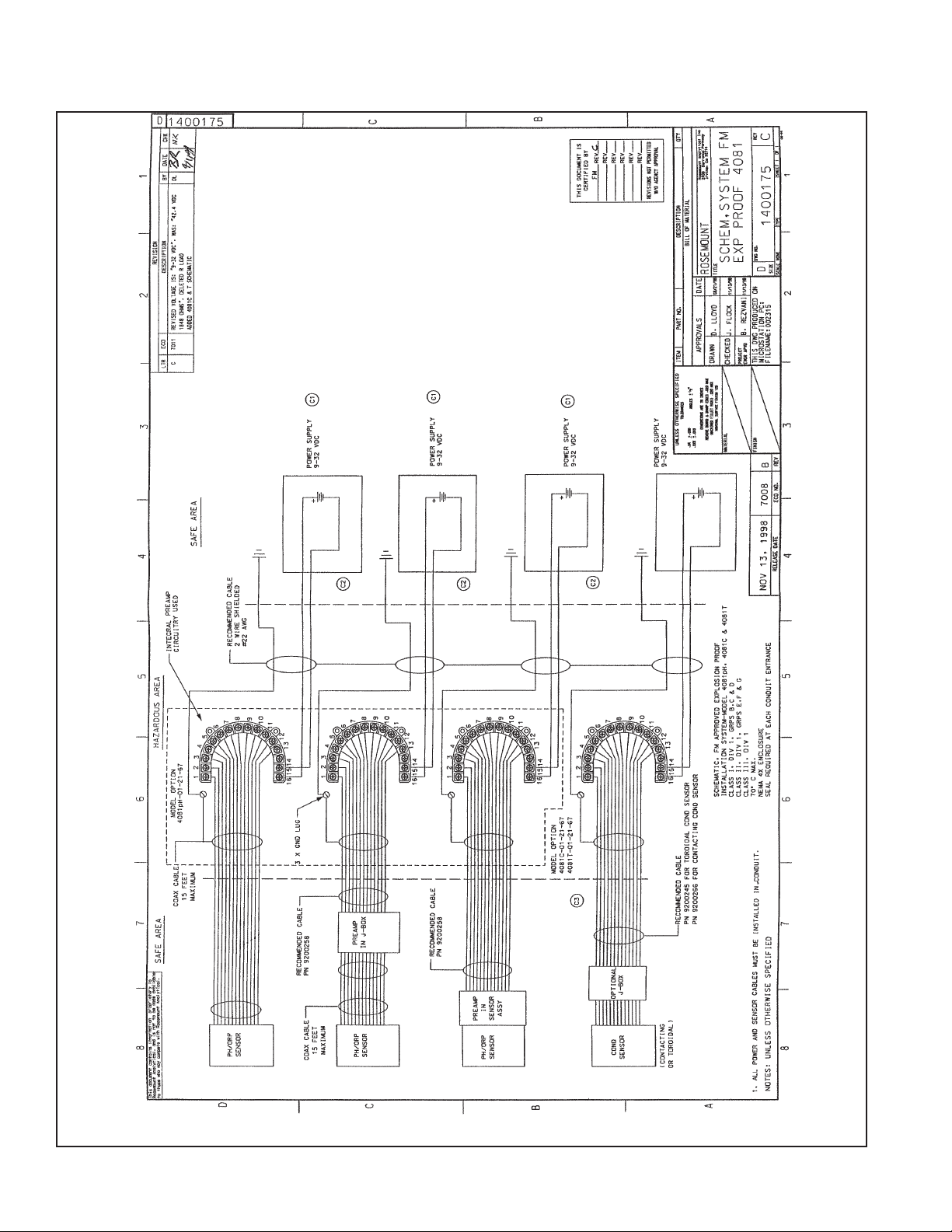
1.3.3 Hazardous Area Installation
In order to maintain the hazardous area rating for installed transmitter, the following drawings must be used:
Figure 1-8. Wiring for FM Explosion-Proof Installation for Model 4081C (Drawing Number 1400175)
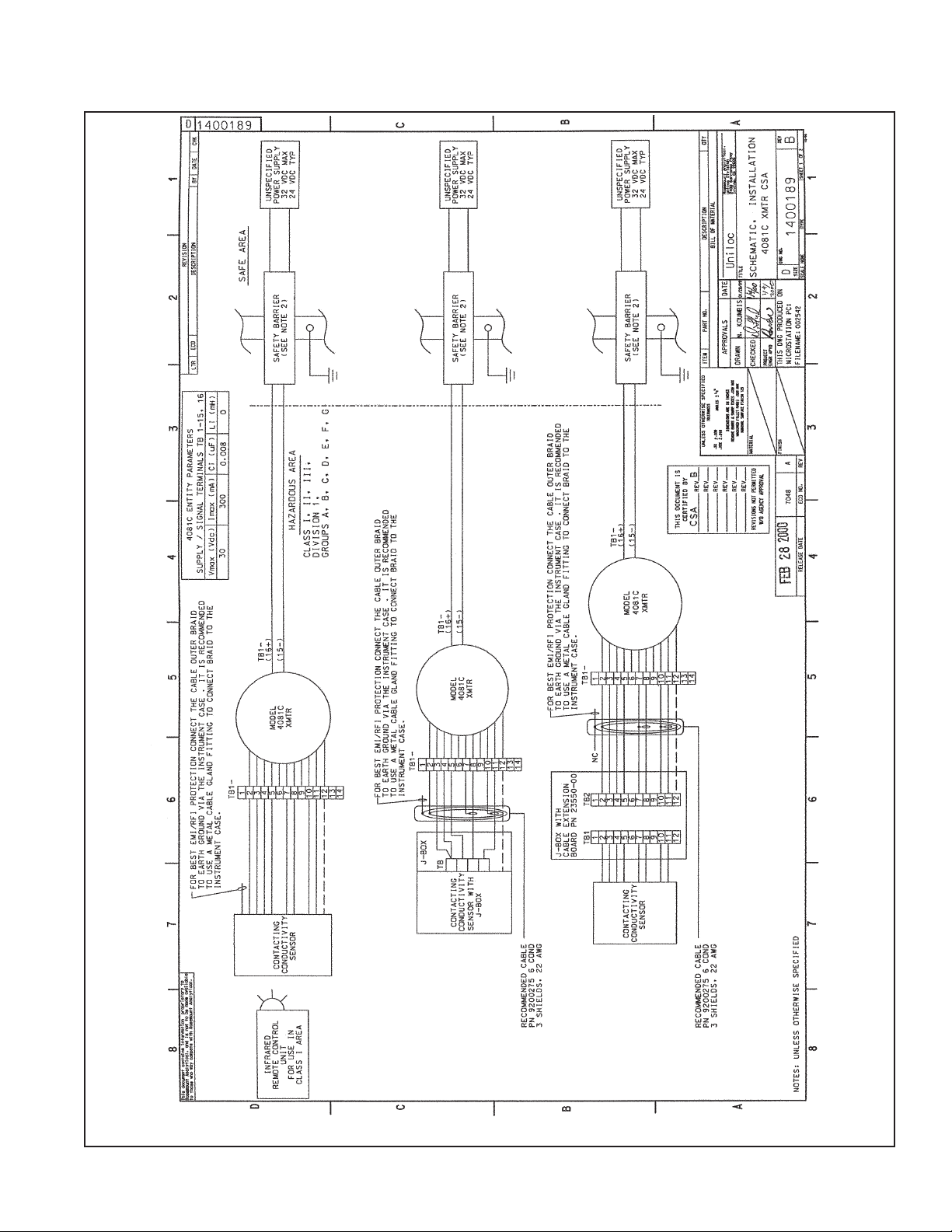
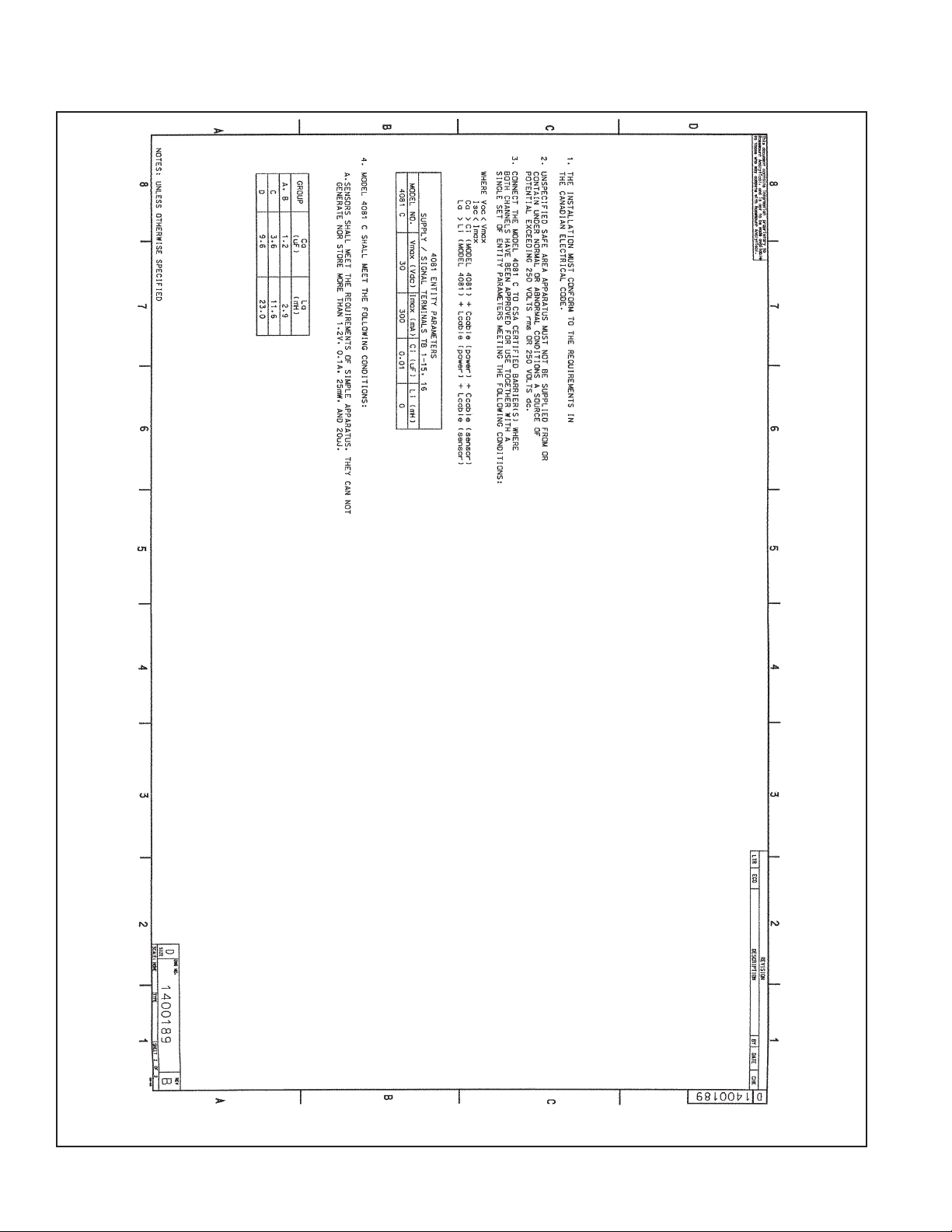
Figure 1-9. Wiring for CSA Intrinsic Safety for Model 4081C (Drawing Number 1400189). See also label below.
Figure 1-10. Wiring for FMRC Instrinsically Safe Installation for Model 4081C (Drawing Number 1400186).
Page 14
1-10
MODELS 4081C SECTION 1.0
INSTALLATION
FIGURE 1-8. EXPLOSION-PROOF INSTALLATION
Page 15
MODELS 4081C SECTION 1.0
INSTALLATION
FIGURE 1-9. CSA INTRINSICALLY SAFE INSTALLATION (1 of 2)
1-11
Page 16
1-12
MODELS 4081C SECTION 1.0
INSTALLATION
FIGURE 1-9. CSA INTRINSICALLY SAFE INSTALLATION (2 of 2)
Page 17

MODELS 4081C SECTION 1.0
INSTALLATION
FIGURE 1-10. FMRC INTRINSICALLY SAFE INSTALLATION (1 of 2)
1-13
Page 18

1-14
MODELS 4081C SECTION 1.0
INSTALLATION
FIGURE 1-10. FMRC INTRINSICALLY SAFE INSTALLATION (2 of 2)
Page 19

2-1
2.1 GENERAL
The Model 4081C transmitter operates in either the
Process or Program modes. The process mode screen
is illustrated in Figure 2-1 and the program mode screen
is illustrated in Figure 2-2.
2.2 DISPLAY
2.2.1 Process Mode (normal operating mode). When
operating in this mode:
• The primary process variable (the conductivity) is
continuously displayed (see 1 in Figure 2-1)
• Engineering units are determined by the process
display mode
• Temperature output is in °F or °C (see 2 in Figure 2-1)
2.2.2 Program Mode (programming or calibrating
mode — step-by-step instructions for programming
and calibrating the transmitter are given in Sections
4.0 and 5.0, respectively). When operating in this mode
the following information is provided on the instrument
display:
• Continuous display of the primary process variable
is still available.
• Menus are displayed below the process variable.
The active subset title is in bold print (see 1 in
Figure 2-2).
CALIBRATE PROGRAM DIAGNOSE
CALIbrAtE
EXIT NEXT ENTER
1000
mS/cm
F
A
U
L
T
H
O
L
D
5
4
1
3
MODELS 4081C SECTION 2.0
OPERATION OVERVIEW
SECTION 2.0
OPERATION OVERVIEW
2
FIGURE 2-1. Process Display Screen
11000000
mS/cm
25.0C
FIGURE 2-2. Program Mode Display Areas
• Security ID (see Section 4.3, step 10) and prompts
are displayed below the segments (see 2 and 3 in
Figure 2-2).
• FAULT is displayed (see 4 in Figure 2-2) when a
transmitter disabling condition occurs. When in the
fault mode, the fault indicator lights up and the
process variable flashes. The program mode must
be entered to see the descriptive fault message.
• HOLD (see 5 in Figure 2-2) becomes visible when-
ever the transmitter is placed in the hold, test, or
multidrop function. Hold is most often used when
servicing/cleaning the sensor.
2
1
Page 20

2-2
2.3 INFRARED REMOTE CONTROL (IRC)
The IRC is the most convenient way to calibrate, program, or access the diagnostics in the transmitter. It
operates the same as other remote controllers.
For best operation, the IRC should be within ten feet of
the transmitter and aimed directly at the infrared sensor
window (small square window at top of display) at an
angle of no more than fifteen degrees. The amount of
ambient light may also affect IRC communication.
2.3.1. The overall menu structure is shown in Figure 2-4.
The top level functions available to the IRC (CAL,
PROG, and DIAG) are shown on the display with the
active menu segment highlighted as described in
Section 2.2.
2.3.2. Menu Keys. The three primary menu structures
are Calibrate (CAL), Program (PROG), and Diagnose
(DIAG). They are shown horizontally on the screen and
have separate keys on the IRC (see 1, 2, and 3 in Figure
2-3). Pressing the labeled key will provide access to that
menu.
2.3.3. Program Command Keys. The three program
command keys are labeled ENTER, NEXT, and EXIT
(see 4, 5, and 6 in Figure 2-3). These keys are used as
follows:
ENTER: This advances down through the submenus to the prompts, will save the new value,
and activate NEXT.
NEXT: This advances the program to the next
sub-menu.
EXIT: This key is used to abort the current submenu operation and return to the previous
menu segment.
2.3.4. Editing Keys. These keys are used to edit input
variables (see Figure 2-3). The left/right arrows change
the location of the prompt and causes the integer to
flash. These also allow access to the measurement unit
and decimal place location. When a flashing mnemonic
appears on the display, the UP and DOWN arrow keys
scroll up or down through the list. When numbers are
shown, the UP and DOWN keys change the value of
the digit.
MODELS 4081C SECTION 2.0
OPERATION OVERVIEW
9
8
6
5
4
3
2
1
Editing
keys
FIGURE 2-3. Infrared Remote Control
2.3.5. Special Entry Keys. These keys provide system
level operations.
RESET: Aborts the current operation and
returns to the process display screen (see 8 in
Figure 2-3).
HOLD: Accesses prompt to toggle between
enable and disabling of this function (see 9 in
Figure 2-3).
2.4 DIAGNOSTIC MESSAGES
Whenever a warning or fault has been triggered, diagnostic messages are displayed to aid in problem solving. These messages flash alternately with the
temperature reading.
If more than one message has been generated, the
warning or fault messages will alternate with the regular
readings.
See Section 6.0 Diagnosis and Troubleshooting for
message meaning and possible causes.
Page 21

2-3
MODELS 4081C SECTION 2.0
OPERATION OVERVIEW
CALIBRATION
AdJ SLOPEtEMP SLOPE
AbS C
CELL 0
FActor
UEr 4081C
tSLOPE
Shouu FLt
1000
25.0C
Model 4081C
Process Display
Screen
mS/cm
CALIbrAtE
CELL COnSt SEnSOr 0
tEMP AdJ
tEMP
dISPLAY
PROGRAM
Process Display
FIGURE 2-4. Menu Tree
DIAGNOSTICS
2.5 MENU PROGRAM TREE
The software has been designed with the user in mind. It uses a simple three layer setup to calibrate and program (configure)
the instrument and display instrument diagnostic conditions (see Figure 2-4).
Page 22

2-4
Page 23

3-1
MODELS 4081C SECTION 3.0
FACTORY PROGRAMMED SETTINGS
SECTION 3.0
FACTORY PROGRAMMED SETTINGS
GENERAL
The Models 4081C transmitter is shipped with factory programmed settings.
This table is useful in several ways:
1. It gives an overview of variables that can be changed, the mnemonics, and the factory settings.
2. It identifies more detailed sections for each menu.
3. It shows the factory settings.
4. It provides space to input specific values.
VARIABLE NAME
MNEMONIC FACT
ORY SETTINGS CUSTOMER SETTINGS
Temperature (Section 4.2)
ttEEMMPP
Auto temperature compensation tAUtO on
Manual temperature tMAn 25.0° C (overridden by auto)
Temperature sensor type tC 100-3
Display (Section 4.3)
ddIISSPPLLAAYY
Measurement type
LLIInnEEAArr,nn SSAALLtt
, Linear
rrSSttvvttYY
, or
nn CCAAttiioonn
Range rAnGE Lo
Temperature (°C or °F) tEMP C
Code COdE 000
Calibrate (Section 5.0)
Calibration constant Cal 500 500
1.0
Cell constant CELL Const (sensor specific)
Sensor 0 Sensor O 0
Temperature setting Temp Adj 025.0
Temperature slope (if already known) adj slope 2.000
Diagnose (Section 6.1)
(Each segment displays the current value in the transmitter.)
Absolute conductivity Abs C 1000 µS
Cell constant cell 1.00
Temperature slope tslope 2.000
Software version
Show fault warnings Showj Flt (enter) none
Table 3-1. Program Variables with Factory Settings*
*Press ENTER after each command to get entry field.
NOTE: Software version is on the serial tag and should match what is in the diagnose segment.
Page 24

3-2
Page 25

4-1
4.1 PROGRAM MENU
The program menu allows configuration of the transmitter values for the display shown on the LCD.
Changes to the operating parameters are made through
the Program menu.
Press the Program menu key, while pointing the Infrared
Remote Control (IRC) at the transmitter to initiate communication. To avoid communicating with more than one
transmitter at a time, each one must have a unique 3
digit code. Entering the “Id” CODE (see Section 4.3,
step 9) of a transmitter will permit access to
programming menus of only that transmitter. For the
MODELS 4081C SECTION 4.0
TRANSMITTER PROGRAM SET-UP
SECTION 4.0
PROGRAM SET-UP
Calibrate Menu
Segments/Commands
Program Menu
Segments/Commands
DIAGNOSE MENU
Segments/Commands
CURRENT OPERATING MENU
FACtOr
EXIT NEXT ENTER
CELL
EXIT NEXT ENTER
AbSC
EXIT NEXT ENTER
FIGURE 4-1. Program Menu and Menu Segments
SEnSOr
EXIT NEXT ENTER
CALIbrAtE
EXIT NEXT ENTER
CELL COnSt
EXIT NEXT ENTER
tSLOPE EXIT
NEXT ENTER
UEr 4081t
EXIT NEXT ENTER
KEYPRESS COMMANDS
CalibrateProgram Diagnose
IIdd 000000
Exit Enter
Menu Segment/Prompt
Area
sequence to enter this code, press the PROG key and
go to the last (display) element of the sub-menu.
The sub-menus are shown in the message display area.
These define which prompts are shown (See Figure 2-2).
The prompts have fields that are used to edit the parameters of the menu currently active. Editing is accomplished by scrolling through a predetermined list of
responses. See Figure 4-1 for the sub-menus available
under the program menu.
See Table 4-1 for Program Menu sequence/ commands
and mnemonics.
dISPLAY
EXIT NEXT ENTER
tEMP
EXIT NEXT ENTER
AdJ SLOPE
EXIT NEXT ENTER
tE
M
P AdJ
EXIT NEXT ENTER
tEMP SLOPE
EXIT NEXT ENTER
ShoWjFLt
EXIT NEXT ENTER
Page 26

4-2
MODELS 4081C SECTION 4.0
TRANSMITTER PROGRAM SET-UP
4.2 TEMPERATURE PARAMETERS
1. Press the Program key (PROG) on the IRC, enter the security code if
necessary, and press NEXT.
While tEMP is displayed, press ENTER to get the first prompt of the
tEMP menu segment.
2. The tAUtO prompt is used to enable (ON) or disable (OFF) auto temperature compensation for all conductivity process measurements. If
On is selected, an equation is used to temperature compensate all
process measurements to 25 °C and will be the reported temperature
on the process display. The default value is On. Press ENTER.
3. The tMAn prompt is used to enter a temperature value that the com-
pensation equation will use (overrides auto). The actual process temperature, however, will be shown on the main screen. The temperature
display mode determines the units used. Absolute conductivity is measured using the default value of 025.0 °C. Use the IRC editing keys to
change the value only if some determination other than absolute conductivity is required. Press ENTER.
4. The tC prompt matches the instrument to the type of temperature sensor being used. Listed type available is 100-3 (3-wire Pt100 RTD). The
IRC editing keys scroll through the listing. The default value is 100-3.
Press ENTER.
NOTE
4-wire Pt100 is displayed but is not available in
toroidal sensors.
5. Press EXIT to return to normal operation or NEXT to go to the display
sub-menu.
tEMP
EXIT NEXT ENTER
Return
to Main
Screen
To display
menu segment.
R
T
D
3 Wire RTD - Connected to an instrument designed to accept three wire
input. Compensation is achieved for lead resistance (cable wire resistance
is affected by cable length and temperature change). This is the most commonly used configuration.
+
-
The following procedures are used to select between automatic temperature compensation, absolute conductivity, manual
temperature compensation, and RTD sensor type. To access the temperature parameters, do the following:
tAUt
O On
EXIT ENTER
t
C 1 00-3
EXIT ENTER
t
M
An 0 25.0
EXIT ENTER
Sense
FIGURE 4-2. RTD Sensor Connections
Page 27

4-3
MODELS 4081C SECTION 4.0
TRANSMITTER PROGRAM SET-UP
4.3 DISPLAY UNITS
The following procedures are used to select the display menus, calculation formulas, process variable and temperature
display units. The factory settings are shown with each variable. To access the display sub-menu, do the following:
t
EM P
EXIT NEXT ENTER
dISPLAY
EXIT NEXT ENTER
Manrng “1”
EXIT ENTER
tYP “LInEAr”
EXIT ENTER
Autorng
“On”
EXIT ENTER
COdE “000”
EXIT ENTER
t
EMP “C”
EXIT ENTER
rAngE “Lo”
EXIT ENTER
1. Press PROG key on remote control.
2. Enter ID Code number (if necessary). See step 7.
Press NEXT twice to scroll through the tEMP menu segment
to the dISPLAY menu segment.
3. When the dISPLAY menu is displayed, press ENTER to
access the first prompt in the display sequence.
4. The tYP prompt determines how conductivity is displayed:
“LInEAr” = linear conductivity; “n SALt” = neutral salt (ultrapure water); “rStvtY” = resistivity; and “CAtion” = cation conductivity. The IRC editing keys are used to scroll through the
list. Choose the desired type and press ENTER.
5. The rAnGE prompt is used to determine the measurement
range limit (High or Low). The IRC editing keys are used to
scroll between these. The default is LO. Press ENTER.
6. The Autorng (auto range) is a toggle (or increment between
On and Off) that enables or disables the auto range function.
Press the up or down arrow to select On or Off as desired.
The On setting turns on the auto range function and preempts Manrng. Press ENTER.
NOTE
The transmitter is shipped with range=Lo since
this is the most frequently used setting. Others
are shown in Table 4-1 below.
Return to
Menu
Screen
Continued on page 4-4.
TABLE 4-1. Transmitter Settings*
* Assumes 1.0 cell constant.
Software Settings
Process Stream Type Range
Contacting Conductivity in the range
20-2,000 µs/cm (default) LInEAr Low
Contacting Conductivity
in the range 2,000 to 20,000 µs/cm LInEAr High
Ultrapure water up to 20µs/cm n SALt Low
Ultrapure water Resistivity
to 50 MΩ-cm rStvtY Low
Page 28

4-4
MODELS 4081C SECTION 4.0
TRANSMITTER PROGRAM SET-UP
7. The Manrng (manual range) prompt asks for the fixed
range used by the process measurement. Autorng
must be Off to enable.
For the “Hi” range setting, use Table 1-4 for range limits in the conductivity mode (C).
For the “lo” range, use Table 1-4 for the linear conductivity mode, Table 1-2 for the neutral salt mode, or
Table 1-3 for the resistivity mode.
Select the desired range using the up and down arrow
keys. Press ENTER.
8. The tEMP prompt is used to determine which units will
be used with the temperature reading displays. Units
available are °C or °F. The IRC editing keys are used to
scroll between these. The default value is °C. Choose
the appropriate units and press ENTER.
9. The COdE prompt is used to identify the security “Id”
Code number of the unit (see Figure 4-3). The number
entered here determines the “Id” code number used to
unlock the security feature and allow access to the
menu programs and program segments. The limits are
between 000 and 999. New transmitters are shipped
with the code set to 000 which disables the feature,
(allows access to all menus). If no key is pressed for
two minutes the code will need to be entered again.
Use the IRC editing keys to set the desired security
code. Press ENTER.
NOTE
If this code has been changed or the number misplaced, entering 555 at the “Id” prompt and press-
ing ENTER will display the current code. Access
will not be granted, however, until you EXIT to the
process display, select program to enter (CALI-
BRATE, PROGRAM, or DIAGNOSE), press
ENTER again, and enter CODE # just displayed.
10. Press EXIT to return to normal operation.
FIGURE 4-3. Security Code prompt.
CALIBRATE PROGRAM DIAGNOSE
IIdd 00 00 00
EXIT NEXT ENTER
TABLE 4-2. Program Menu Mnemonics
HoLd
Transmitter on hold
FAULt
System disability fault condition
tE
M
P
Temperature menu header
tAUtO
Automatic temperature compensation
t
M
An
Manual temperature compensation
tC
Temperature sensor type
dISPLAY
Display menu header
tYP
Conductivity measurement type
rAnGE
LO/HI measurement range
Autorn
Autorange on or off toggle
Manrng
Manual ranges used for narrow, higher linearity
Associated with range
When range = Hi, Manrng = 1, 2, 3
When range = Lo, Manrng = 1, 2, 3, 4
(see Table 1-2)
tE
M
P
°C / °F toggle selection
COdE
Security code
Page 29

5-1
CURRENT OPERATING MENU
KEYPRESS COMMANDS
Menu Segment/Prompt
Area
MODELS 4081C SECTION 5.0
START-UP AND CALIBRATION
5.1 ACCESSING THE CALIBRATE MENU
The “Calibrate” menu allows the transmitter and sensor
loop to be calibrated to known temperature and conductivity values. This menu also accesses two-point temperature calibration operation to establish the temperature
slope.
Calibrating the Transmitter/Sensor loop may proceed
after proper power and sensor wiring.
Figure 5-1 illustrates the relationship between the
Calibrate Menu and its sub-menus. Each sub-menu
leads to a series of prompts that are used to edit transmitter parameters.
Calibration may be successfully accomplished if the factory settings identified in Table 3-1 of Section 3.0 are satisfactory or if the transmitter has been properly programmed per Section 4.0 to match the intended process
application requirements.
Calibrate Menu
Segments/Commands
Program Menu
Segments/Commands
DIAGNOSE MENU
Segments/Commands
fACtOr
EXIT NEXT ENTER
CELL
EXIT NEXT ENTER
AbSC 1000
EXIT NEXT ENTER
FIGURE 5-1. Calibration Menu Segments
SEnSOr O
EXIT NEXT ENTER
CALIbrAtE
EXIT NEXT ENTER
CELL COnSt
EXIT NEXT ENTER
tSLOPE
EXIT NEXT ENTER
UEr 4081C
EXIT NEXT ENTER
dISPLAY
EXIT NEXT ENTER
tEMP
EXIT NEXT ENTER
AdJ SLOPE
EXIT NEXT ENTER
tE
M
P AdJ
EXIT NEXT ENTER
tEMP SLOPE
EXIT NEXT ENTER
Sho
Wj
FLt
EXIT NEXT ENTER
Calibrate Program Diagnose
IIdd 000000
Exit Enter
SECTION 5.0
START-UP AND CALIBRATION
Page 30

MODELS 4081C SECTION 5.0
START-UP AND CALIBRATION
5.2 CALIBRATE MENU
There are three separate calibration procedures, depending on the measurement needs and the situation. These are general calibration, low conductivity calibration, and standardization.
CALIbrAtE
EXIT NEXT ENTER
CELL COnSt
EXIT NEXT ENTER
Return
to Main
Screen
tEMP Adj
menu segment
CAL 1000
EXIT ENTER
CELL 1 .000
EXIT NEXT ENTER
CALIbrAtE
EXIT NEXT ENTER
Return
to Main
Screen
CELL COnST
menu segment
CAL 1000
EXIT ENTER
CALIbrAtE
EXIT NEXT ENTER
CELL COnSt
EXIT NEXT ENTER
Return
to Main
Screen
SEnSOR0
menu segment
CELL 1 .000
EXIT NEXT ENTER
5.2.1. General Calibration. This calibration menu is used for all conductivity
applications. At the Cell Const prompt,
ENTER will access the step to allow
entry of the cell constant for the sensor
you are using. Temperature compensation is input further down in the menu
(see Section 5.3).
5.2.2. Low Conductivity. This calibration method is used to enter the calibration constant (if available) for the sensor
you are using (see Section 5.5). You
must be in the “L” or “r” display mode
(see Section 4.3).
5.2.3. Calibration Adjustments (Standardization). Once the transmitter is ini-
tially calibrated, it may be necessary to
fine tune it over time. This can be done
using either a standard solution (see
Section 5.4) or an on-line sample (see
Section 5.6). In either case pressing
ENTER at the calibrate prompt will
access the CAL prompt where the
adjustment can be made.
Section 5.2.2 Menu
Section 5.2.3 Menu
Section 5.2.1 Menu
5-2
Page 31

5-3
MODELS 4081C SECTION 5.0
START-UP AND CALIBRATION
SEnSOr 0
EXIT NEXT ENTER
CALIbrAtE
EXIT NEXT ENTER
CELL COnSt
EXIT NEXT ENTER
AdJ SLOPE
EXIT NEXT ENTER
tEMP AdJ
EXIT NEXT ENTER
tE
M
P SLOPE
EXIT NEXT ENTER
Return
to Main
Screen
SEnSOr 0
EXIT ENTER
CELL “1” 000
EXIT NEXT ENTER
tSLOPE 2000
EXIT ENTER
tEMP 0 250
EXIT ENTER
t1 2000
EXIT NEXT ENTER
t2 2000
EXIT NEXT ENTER
5.3 CALIBRATE MENU (Contacting)
For calibration using solutions of known conductivity, see
Section 5.4.
For low conductivity (L) and resistivity (r) measurements,
see Section 5.5.
Figure 5-1 illustrates the Calibrate Menu.
1. To access the “Calibrate” menu, press the Cal key on
the Infrared Remote Control. If security has been
enabled, the secondary process display will be
replaced with a prompt asking for the “Id”. Using the
IRC editing keys, enter the “Id”. If the correct “Id” is
entered, the CALibrAtE sub-menu will appear when
ENTER is pressed.
2. If the calibrate sub-menu does not appear when
ENTER is pressed, see Section 4.3 (step 8) for procedure to find correct code.
3. When the calibrate sub-menu has been accessed,
press the NEXT and then ENTER to access the
CELL menu segment with the flashing cell constant
prompt.
4. Using the arrow keys on the IRC, enter your sensor’s
cell constant.
5. Press ENTER to install the cell constant into the
transmitter memory and return to the CELL COnSt
sub-menu.
Page 32

MODELS 4081C SECTION 5.0
START-UP AND CALIBRATION
5-4
6. Press NEXT to enter the SEnSOr 0 menu and press
ENTER to access the SEnSOr 0 sub-menu. With the
sensor attached and in air, press ENTER again to zero
the sensor and return to the SEnSOr 0 sub-menu.
7. Press NEXT and then ENTER to access the tEMP
sub-menu with flashing prompt. With the sensor in any
solution of known temperature, allow the temperature
of the sensor to stabilize. Use the editing keys of the
IRC to change the displayed value as needed.
8. Press ENTER to standardize the temperature reading
and return to the tEMP AdJ sub-menu.
9. Press NEXT to enter the tEMP SLOPE menu.
The correct temperature slope must be entered into
the transmitter to ensure an acceptable process variable measurement under fluctuating process temperature conditions. This can either be done using a twopoint calibration (see Section 5.3.1) or by inputting the
slope if it is known.
10. If the temperature slope of the process is not known
but you wish to approximate it, refer to the following
guide and press ENTER to proceed on to tSLOPE
sub-menu with flashing prompt. Utilize the IRC editing
keys to generate the desired slope value. Press
ENTER then EXIT to return to the main screen.
Acids: 1.0 to 1.6% per °C
Bases: 1.8 to 2.2% per °C
Salts: 2.2 to 3.0% per °C
Water: 2.0% per °C
5.3.1 Two Point Temperature Calibration.
[Available in “C” type setting only]
1. Press ENTER to access the t1 temperature prompt.
• obtain a grab sample of the actual process to be
measured.
• immerse the sensor in the process solution. The
sensor body must be held away from the bottom and
the sides of the sample's container at a distance at
least equal to the diameter of the sensor, and the
sensor cable must not be allowed to contact the
solution. Shake the sensor to ensure that no air
bubbles are present.
• allow the sensor to acclimate to the temperature of
the process solution (10 min.). The process solution
temperature must be stable
. Record the conductivity at t1. Press ENTER to enter t1 conductivity and to
move to t2 prompt.
2. Using a hotplate with a stirrer, change the temperature of the process solution by at least 20°C. Allow
the sensor to acclimate to the new temperature (10
min.). The new reading must be stable.
NOTE
You can also allow a hot sample to cool
down for this step.
3. Using the editing keys of the IRC, adjust the t2 con-
ductivity to equal t1 conductivity. Press ENTER .
4. Press EXIT twice to return to the main screen.
5. Proceed to Section 5.4 for Bench Calibration.
5.4 BENCH CALIBRATION FOR INITIAL
START-UP
1. With the sensor in a standard solution of known conductivity value, allow the temperature of the sensor to
stabilize (10 min).
2. To access the CALIbrAtE menu, press the CAL but-
ton on the IRC.
3. Press ENTER to access the CAL segment with flashing prompt.
4. Use the IRC editing keys to indicate the conductivity
values of the standard solution on the screen.
5. Press ENTER then EXIT to enter the standard solution
value and exit again return to the main screen.
CALIbrAtE
EXIT NEXT ENTER
CAL 1000
EXIT ENTER
Return
to Menu
Screen
CELL COnSt
menu segment
Page 33

MODELS 4081C SECTION 5.0
START-UP AND CALIBRATION
5-5
5.5 CALIBRATE MENU
(Low Conductivity/Resistivity)
5.5.1 INITIAL SET-UP AND CALIBRATION
Follow these calibration instructions for initial set-up where
Type “L” low conductivity and Type “r” resistivity measurements are being made.
Low conductivity instruments are difficult to calibrate
using standard solutions. The interferences of carbon
dioxide in air and surface contamination in sample containers lead to substantial errors.
To prevent these errors, Rosemount low-conductivity
cells are pre-calibrated and are marked with a calibration
constant on their cables.
Once this calibration constant number is entered into the
instrument and a temperature calibration is performed,
then the loop is calibrated and ready to be placed on-line.
1. To access the Calibrate menu, press the Cal key on
the Infrared Remote Control. If security has been
enabled, the secondary process display will be
replaced with a prompt asking for the “Id”. Using the
IRC editing keys, enter the “Id”. If the correct “Id” is
entered, the calibrate menu will appear when ENTER
is pressed.
2. If calibrate menu does not appear when ENTER is
pressed, see Section 4.3 (step 8) for procedure to find
correct code.
3. When the calibrate menu has been accessed, press
the NEXT and then ENTER to access the CELL menu
with the flashing cell constant prompt.
4. Utilizing the edit keys on the IRC, generate the correct
cell constant of the sensor being used (for example,
.01, .10, 1.00, 10.0).
5. Press ENTER to install the cell constant and access
the CAL sub-menu with flashing calibration constant
prompt. Use the IRC edit keys to select the sensor's
calibration constant. This is a value between 0 and
999 found on the sensor cable.
6. Press ENTER to install the calibration constant and
return to the CELLCOnSt menu.
7. Continue with the SEnSOr 0 and tEMP AdJ sub-
menus from Section 5.3, steps 6 - 8. Note that the
tEMP SLOPE prompt will not appear in “L” or “r”
modes.
tE
M
P AdJ
EXIT NEXT ENTER
CALIbrAtE
EXIT NEXT ENTER
CELL COnSt
EXIT NEXT ENTER
Return
to Main
Screen
tE
M
P 025. 0
EXIT ENTER
CELL 1000
EXIT NEXT ENTER
CAL1000
EXIT ENTER
Page 34

MODELS 4081C SECTION 5.0
START-UP AND CALIBRATION
5-6
CALIbrAtE
EXIT NEXT ENTER
Return
to Main
Screen
CAL 1000
EXIT NEXT ENTER
to next
menu
segment
TABLE 5-1. CALIBRATE MENU MNEMONICS
CALIbrAtE Calibrate menu header
CAL Sensor calibration
tE
M
P SLOPE Sub-menu header
t1 First temperature conductivity value for slope calculation
t2 Second temperature conductivity value for slope calculation
Adj SLOPE Sub-menu header
tSLOPE Slope adjustment %/°C
CELL COnSt Sub-menu header
CELL Cell constant value
CAL Cell constant correction value (L/r)
SEnSOr Sub-menu header
SEnSOr 0 Sensor "0" (performed in air)
tE
M
P AdJ Sub-menu header
tE
M
P Temperature adjustment °C/°F
5.6 ON-LINE CALIBRATION
For maximum accuracy, calibrate the sensor in the
process. This should be done after the initial transmitter
calibration and periodically thereafter as required.
Refer to Section 5.4 for the procedure.
On-line calibration is well-suited for most conductivity
measurements except ultra pure conductivity and resistivity measurements. These special applications require specialized tools to perform an accurate on-line comparison. A
certified conductivity instrument with a certified flowthrough conductivity cell, like the Rosemount Portable
Validation Instrument, can be used for this purpose.
Type “C” only
Type “L” or “r”
Page 35

6-1
6.1 OVERVIEW
The Model 4081C transmitter automatically monitors for
fault conditions. The Diagnose Menu allows the current
variable settings to be reviewed and shows fault messages indicating problems detected. Figure 6-1 illustrates
the relationship between the Diagnose Menu and its
sub-menus. The factory-set diagnose values are illustrated in Figure 6-2. The mnemonics are defined in
Table 6-1.
6.1.1 TROUBLESHOOTING
Step 1 Look for a diagnostic fault message on the
display to help pinpoint the problem. Refer to
Table 6-2 for an explanation of the message and
a list of the possible problems that triggered it.
Step 2 Refer to the Quick Troubleshooting Guide, Table
6-3, for common loop problems and the
recommended actions to resolve them.
MODELS 4081C SECTION 6.0
DIAGNOSIS AND TROUBLESHOOTING
SECTION 6.0
DIAGNOSIS AND TROUBLESHOOTING
Step 3 Follow the step by step troubleshooting flow
chart, offered in Figure 6-6, to diagnose less
common or more complex problems.
6.1.2 DISPLAYING DIAGNOSTIC VALUES
The DIAG key on the IRC is used to access the
Diagnosis Menu. The menu flow is shown in Figure 6-2
and the mnemonics are defined in Table 6-1.
The ShoW FLT sub-menu can be entered to show the
last three faults/warnings. The most recent is displayed
first; NEXT scrolls through the remaining faults. Pressing
EXIT clears all fault/warnings and returns the SHoW FLT
segment. Disconnecting power removes all fault messages from memory. The nonE is displayed when no
faults/warnings have occurred.
CURRENT OPERATING MENU
KEYPRESS COMMANDS
Menu Segment/Prompt
Area
Calibrate Menu
Segments/Commands
Program Menu
Segments/Commands
DIAGNOSE MENU
Segments/Commands
fACtOr
EXIT NEXT ENTER
AbSC
EXIT NEXT ENTER
FIGURE 6-1. Diagnose Menu Segments
tSLOPE
EXIT NEXT ENTER
dISPLAY
EXIT NEXT ENTER
tE
M
P
EXIT NEXT ENTER
AdJ SLOPE
EXIT NEXT ENTER
tE
M
P SLOPE
EXIT NEXT ENTER
ShoWJFLt
EXIT NEXT ENTER
SEnSOr O
EXIT NEXT ENTER
CELL
EXIT NEXT ENTER
UEr 4081C
EXIT NEXT ENTER
CALIbrAtE
EXIT NEXT ENTER
CELL COnSt
EXIT NEXT ENTER
tEMP AdJ
EXIT NEXT ENTER
CalibrateProgram Diagnose
IIdd 000000
Exit Enter
Page 36

6-2
MODELS 4081C SECTION 6.0
DIAGNOSIS AND TROUBLESHOOTING
AbSC Absolute conductivity (µS/cm or mS/cm)
CELL Sensor cell constant (used in C mode)
CAL Calibration constant (used in “L” or “r” mode)
FActOr Calibration factor
nonE No fault messages in memory
Sho
WJ
FLt
Show fault messages
tSLOPE Temperature slope in %/ °C
UEr Software version
Calibrate Program Diagnose
Exit Enter
Return to
Main
Screen
TABLE 6-1. Diagnostic Variables Mnemonics
AbS C 1000
EXIT NEXT
CELLCOnST
EXIT NEXT
UEr 4081C
EXIT NEXT
ShoWjFLt
EXIT NEXT ENTER
nonE
EXIT NEXT
FActor 1.000
EXIT NEXT
tSLOPE 2.000
EXIT NEXT
CAL 500
EXIT NEXT
CELL 1.000
EXIT NEXT
µS
(L & r)
(C)
(C)
(L, r)
FIGURE 6-2. Diagnose Values
Page 37

6-3
MODELS 4081C SECTION 6.0
DIAGNOSIS AND TROUBLESHOOTING
6.2 FAULT CONDITIONS
Three classes of error conditions/problems can be
detected and are differentiated by the diagnostic program. System disabling problems are faults caused by
failures in the loop or significant variations in the
process. System non-disabling problems are warnings
and deal with inputted signals/values or Analog to
Digital conversion settings. The third class of detected
problems are error messages and occur when the calibration limits are exceeded.
6.2.1 DISABLING FAULTS
1. Both FAULT and HOLD annunciation fields will
become active (see Figure 6-3).
2. The process variable will flash at the rate of 1 second ON and 1 second OFF.
3. The appropriate fault message alternates with the
normal Temperature display (see Figure 6-3).
CALIBRATE PROGRAM DIAGNOSE
“ LInE FAIL”
EXIT NEXT ENTER
1000
µS/cm
F
A
U
L
T
H
O
L
D
FIGURE 6-3. Disabling Fault Annunciation
CALIBRATE PROGRAM DIAGNOSE
“ InPut WJArn”
EXIT NEXT ENTER
1000
µS/cm
FIGURE 6-4. Non-Disabling Warning Annunciation
6.2.2 NON-DISABLING WARNINGS
When a non-system disabling condition occurs, a
warning message is displayed. The Process variable
does not flash. The appropriate message alternates with
the Temperature display (see Figure 6-4).
If more than one fault exists, the display will sequence
through the diagnostic messages. This will continue until
the cause of the fault has been corrected.
F
A
U
L
T
H
O
L
D
Page 38

6-4
MODELS 4081C SECTION 6.0
DIAGNOSIS AND TROUBLESHOOTING
6.3 DIAGNOSTIC MESSAGES
The Model 4081C transmitter’s diagnostics constantly monitor the system for possible problems. If an operational problem is encountered, check the display for a fault or error message. These are displayed in the Temperature segment of
the display. Note the message and refer to Table 6-2 for a description of possible problems that may have triggered the
diagnostic message.
Message Description Action
Faults
tE
M
P LO Low temperature limit of 0.0° C is exceeded (too low). Check wiring or sensor/process temp.
Check RTD
tE
M
P HI High temperature limit of 100.0° C is exceeded (too high). Check wiring or sensor/process temp.
Check RTD
LInE FAIL The RTD sense line fault limits have been exceeded Check wiring or Check Program/Temp
for the sensor. menu setting to verify the 100-3
sensor type connected.
CPU FAIL The CPU has failed during RAM or EEPROM Recycle the power. If persistent contact
verification. the factory.
FACt FAIL The transmitter has not been accurately factory calibrated. Contact factory.
rO
M
FAIL The PROM failed the check-sum test. Contact factory.
CYCLE P
W
r A wrong value was detected during power-up. Recycle the power.
Sensor fail Conductivity too low or open Verify the solution type setting
Simulate sensor (Figure 6.5) to check
transmitter
Replace sensor
Warnings
InPut WArn The compensated conductivity limit of 9999 mS/cm is Verify the conductivity range setting.
exceeded.
AdC WArn An analog to digital conversion error has occurred. Recycle the power.
Errors
CAL Err A calibration error has occurred between the standard Press RESET and repeat.
and process.
tSLOPE Err The limit for t2 in a two point calibration has been Press RESET and repeat the
exceeded ( > 5%). calibrate/temp slope menu setting.
-0- Err Sensor Zero limit has been exceeded. Press RESET and repeat the cali-
brate/sensor menu setting.
WRITE Err An attempt to write on the EEPROM has failed. The jumper JP-1 on the CPU board
has been removed.
TABLE 6-2. Diagnostic Fault Messages.
Page 39

6-5
MODELS 4081C SECTION 6.0
DIAGNOSIS AND TROUBLESHOOTING
SYMPTOM ACTION
Wrong temperature reading. Perform a temperature standardization. Verify sensor's RTD.
Suspected temp. compensation problem. Resistance vs. temp.; see Table 6.4; temperature may be out of range of sensor.
Check wiring. Check jumpers and RTD configuration on display
Display segments missing. Display inoperable. Replace Display board. If fault continues, check CPU board.
Analyzer locks up; won't respond. Replace PCB stack.
Press Reset on IRC.
Check batteries in IRC.
Erratic displays. Check sensors in process.
Transmitter won't respond to IRC key presses. Verify and clean ribbon cable connection on CPU board.
Check batteries in IRC
Key press gives wrong selection. Replace IRC. Check ribbon cable connection on CPU board.
No display or indicators. Check power connections. Replace PCB stack.
”Excess Input” Check sensor wiring.
“Reverse Input” Perform sensor zero.
“Check sensor zero” Analyzer will not zero; place sensor in air and perform zero routine (see Section 5.2).
Table 6-3 identifies some of the more common symptoms and suggests actions to help resolve a problem. In general,
wiring is most commonly at fault.
6.4 QUICK TROUBLESHOOTING GUIDE
TABLE 6-3. Quick Troubleshooting Guide.
When it is apparent by grab sample analysis that the
transmitter is giving inaccurate readings, the following procedure should be followed.
A. A quick visual inspection of the installation may identify
the problem. Check to be sure that the transmitter is
mounted securely and that its internal parts are properly connected.
B. Recheck to ensure the power supply is connected to
the correct pins in the transmitter and that power is
being received.
C. Check the sensor to transmitter terminal wiring and that
all connections are tight. Most error messages are generated by incorrect wiring and will indicate if the RTD or
the toroid are connected incorrectly.
D. The sensor must be immersed into the process stream
to the top of the toroid.
E. Verify that the sensor is clean and the process is flow-
ing through and around the toroid.
6.4.1 FIELD TROUBLESHOOTING
Page 40

6-6
6.5 SYSTEMATIC TROUBLESHOOTING
Not all the problems encountered will be typical. If the
Quick Troubleshooting Guide will not resolve the error,
then try the step-by-step approach offered in this section.
Conductivity Measurement
Problem (in the process)
Remove the sensor from process
and place sensor in air. Zero transmitter.
Refer to Section 5.2 and 5.3.
OK?
Consult
Service Center
YES
NO
YES
YES
NO
NO
Does problem
still exist?
NOTE:
Before starting this procedure
make sure that all wiring is correct.
FIGURE 6-5. Troubleshooting Flow Chart
Step 1 Follow the applicable troubleshooting flow chart
below:
Step 2 Refer to the tests and instructions indicated by
the flow chart to diagnose the problem.
Place sensor in process and
standardize. Refer to Section 5.2.
OK?
Restart
Transmitter
Remove sensor from process and
test in known conductivity solution
OK?
Check wiring
for short and check
jumpers for correct
configuration
Check diagnostic
messages
Refer to Table 6-2
Check for ground
loops and/or
improper installation
YES
NO
MODELS 4081C SECTION 6.0
DIAGNOSIS AND TROUBLESHOOTING
Page 41

MODELS 4081C SECTION 6.0
DIAGNOSIS AND TROUBLESHOOTING
6.6 RTD RESISTANCE VALUES
Table 6-4 is a ready reference of RTD resistance values
at various temperatures. These are used for test and
evaluation of the sensor.
NOTE
Ohmic values are read across the RTD
element and are based on the manufacturer’s stated values (±1%). Allow
enough time for the RTD element in the
sensor to stabilize to the surrounding
temperature (10 min).
Table 6-4. RTD Resistance Values.
Table 6-5. Conductivity Determination.
FORMULA:
EXAMPLE:
cell constant value x 1,000,000
desired simulated conductivity in µs/cm
.01 x 1,000,000
10 µs/cm
Use the following formula to determine the appropriate resistance value to use to simulate a
conductivity value:
= resistance in ohms
= use 1,000 ohm resistance
6-7
Temperature Pt-100 Pt-1000
(°C) Resistance (ohms) Resistance (ohms)
0 100.00 1000
10 103.90 1039
20 107.79 1078
25 109.62 1096
30 111.67 1117
40 115.54 1155
50 119.40 1194
60 123.24 1232
70 127.07 1271
80 130.89 1309
90 134.70 1347
100 138.50 1385
Page 42

6-8
Page 43

7-1
MODELS 4081C SECTION 7.0
MAINTENANCE
SECTION 7.0
MAINTENANCE
7.1 OVERVIEW
Maintenance consists of "Preventative" and "Corrective"
measures.
7.2 PREVENTATIVE MAINTENANCE
7.2.1 Sensor Maintenance. Sensor maintenance
consists of periodic cleaning of the electrode. If the sensor is coated either mechanically or chemically, the sensor must be cleaned.
A weekly cleaning is a good starting maintenance
schedule. This schedule can then be fine tuned to the
site process.
7.2.2 Transmitter Maintenance. Transmitter maintenance consists of periodic calibration. A monthly calibration is a good starting maintenance schedule. This
schedule can then be fine tuned to the site process.
7.2.3 Initiating HOLD Function For Maintenance. To
place the transmitter into the Hold operational mode prior
to servicing the sensor, press the HOLD key on the IRC.
The message field will respond with a message concerning the present hold condition. Press the IRC editing key
to toggle to the On condition. Press ENTER to activate
HOLD output.
Hold Mode will maintain the operating parameters
regardless of process changes.
The section of the LCD reserved for hold annunciation
(Refer to Figure 7-1) will display HOLD when the transmitter is in the Hold Mode.
Always calibrate after cleaning or replacing the sensor.
To return transmitter to normal operation, press HOLD
on the IRC.
Press the IRC editing key to toggle to the OFF condition.
Press ENTER to disengage the HOLD output function.
1000
µS/cm
F
A
U
L
T
H
O
L
D
FIGURE 7-1. Hold Annunciation
Hold field Illuminated
CALIBRATE PROGRAM DIAGNOSE
22 550CC
EXIT NEXT ENTER
7.3 CORRECTIVE MAINTENANCE
Refer to Figure 7-2 for an exploded view of the 4081C
Transmitter.
Table 7-1 lists suggested spare parts along with part
numbers. Sales and service locations are located on
the back pages of this manual.
Page 44

7-2
FIGURE 7-2. Exploded View of Model 4081C Transmitter
MODELS 4081C SECTION 7.0
MAINTENANCE
}
1
2
6
13
13
9
7
5
8
12
TABLE 7-1. Replacement Parts for Model 4081C Transmitter
Location in Shipping
Figure 7-1 PN Description Weight
1 23811-01 PCB stack consisting of the CPU, communication, and analog boards; 1 lb/0.5 kg
display board is not included; CPU, communication, and analog boards
are factory-calibrated as a unit and cannot be ordered separately
2 23652-01 LCD display PCB 1 lb/0.5 kg
5 33337-02 Terminal block 1 lb/0.5 kg
6 23593-01 Enclosure cover, front with glass window 3 lb/1.5 kg
7 33360-00 Enclosure, center housing 4 lb/1.5 kg
8 33362-00 Enclosure cover, rear 3 lb/1.0 kg
9 6560135 Desiccant in bag, one each 1 lb/0.5 kg
9550187 O-ring (2-252), one, front and rear covers each require an O-ring 1 lb/0.5 kg
12 note Screw, 8-32 x 0.5 inch, for attaching terminal block to center housing *
13 note Screw, 8-32 x 1.75 inch, for attaching circuit board stack to center *
housing
14 33342-00 Cover lock 1 lb/0.5 kg
33343-00 Locking bracket nut 1 lb/0.5 kg
note Screw, 10-24 x 0.38 inch, for attaching cover lock and locking bracket *
nut to center housing
NOTE: For information only. Screws cannot be purchased from Rosemount Analytical.
* Weights are rounded up to the nearest whole pound or 0.5 kg.
Page 45

8-1
MODELS 4081C SECTION 8.0
PRODUCT DATA
SECTION 8.0
PRODUCT DATA
• REMOTE COMMUNICATION IS SIMPLE; use the hand-held infrared
remote controller, DeltaV
1
, or FOUNDATION2Fieldbus host.
• LARGE TWO LINE DISPLAY shows conductivity and temperature.
• SIMPLE, INTUITIVE menus make programming and calibrating easy.
• HIGH ACCURACY (within ±1% of actual conductivity and resistivity
measurement).
• ROBUST NEMA 4X and NEMA 7 ENCLOSURE protects the transmitter from harsh plant environments.
• INTRINSICALLY SAFE DESIGN allows the transmitter to be used in
hazardous environments (with appropriate safety barriers).
• NON-VOLATILE EEPROM MEMORY retains program settings and calibration data during
power failures.
8.1 FEATURES
REMOTE COMMUNICATIONS: Remote communica-
tions with the Model 4081C transmitter is easy. The
hand-held, push button infrared remote controller
works from as far away as six feet. The transmitter
also communicates via any F
OUNDATION fieldbus host,
such as the Fisher Rosemount DeltaV system.
DISPLAY: The 0.8-inch high LCD main display means
conductivity values are easy to read even at a distance. Temperature reading also appears in a 0.3
inch high display.
MENUS: Menu formats for calibration and programming are simple and intuitive. Prompts guide the user
through the basic procedures. Diagnostic and error
messages appear in plain language. There are no
annoying error codes to look up.
Remote Control and Digital Communication
Capability Make Interface Convenient, Regardless
of Transmitter Location: Direct user interface is
achieved via an infrared remote controller that provides access to a self-prompting menu for programming, calibration, standardization, and interrogation.
Digital communication capability through FOUNDATION
fieldbus or AMS (Asset Management Solutions) software stretches the user’s access from anywhere in
the factory to anywhere outside the factory.
1. DeltaV is a trademark of Fisher-Rosemount.
2.
FOUNDATION is a registered trademark of Fieldbus Foundation.
Page 46

MODELS 4081C SECTION 8.0
PRODUCT DATA
8-2
FUNCTIONAL SPECIFICATIONS
Calibration: Calibration is easily accomplished by
immersing the sensor in a known solution and entering its value or entering the cell calibration constant for
ultra pure applications.
Power Supply and Load Requirements: A power
supply voltage of 9 Vdc to 32 Vdc at 22 mA is
required; Intrinsically Safe installations may be limited
to a maximum of 2-3 transmitters per node, depending on the barrier used.
Automatic Temperature Compensation:
3-wire Pt 100 or Pt 1000 RTD
Conductivity: 0 to 200°C (32 to 392°F)
Resistivity: 0 to 100°C (32 to 212°F)
Low Conductivity: 0 to 100°C (32 to 212°F)
Local Readout: LCD display may be set in one of
three positions at 90° increments for optimum legibility independent of mounting. Main display is 4
digits, 20 mm (0.8 in.) tall. Message display is ten
digits 7 mm (0.3 in.) tall
Diagnostics: The internal diagnostics can detect:
Calibration Error Zero Error
Temperature Slope Error Low Temperature Error
High Temperature Error Sensor Failure
Line Failure CPU Failure
ROM Failure Input Warning
Once one of the above is diagnosed, the LCD will display a message describing the failure/default detected.
FOUNDATION Fieldbus:
3 AI Function Blocks: conductivity, temperature,
and absolute conductivity
Execution time: 75 milliseconds
PID Block (optional)
Execution time: 100 milliseconds
Ambient Temperature: – 20 to 65°C. (– 4 to 149°F)
Failure Mode Alarm: When a fault is detected, the
display will indicate a fault.
Configuration Security: Access to the transmitter
configuration and reconfiguration modes may be
restricted via user selected security codes.
Enclosure: NEMA 4X (IP65), weatherproof and corro-
sion resistant; NEMA 7, explosion-proof
CE: EMI/RFI Certification
EN50081-1
EN50082-2
Hazardous Area Classification:
Explosion Proof:
FM: Class I, Div. 1, Groups B, C & D
Class II, Div. 1, Groups E, F, & G
Class III, Div. 1
CSA: Class I, Div. 1, Groups C& D
Class I, Div. 2, Groups A, B, C & D
Class II, Div. 2, Groups E, F & G
Class III, Div. 1
Intrinsic Safety:
FM: Class I, II & III, Div. 1
T4 T AMB= 40°C; T3AT AMB= 70°C
CSA: Class I, Div. 1
T 3C T AMB=40°C; T3 T AMB=80°C
CENELEC: EEx ia IIC
T5 Tamb=40°C; T4 Tamb=60°C
Non-Incendive:
FM: Class I, Div. 2, Groups A, B, C & D
CSA: Class I, Div. 2, Groups A, B, C & D T5
(Tamb=40°C)
PHYSICAL SPECIFICATIONS - General
Housing: Epoxy-polyester painted over low-copper
aluminum. Neoprene O-rings on cover. 160.5 mm
x 175.3 mm x 161.3 mm (6.3 in. x 6.9 in. x 6.4 in.)
Diameter: 155.4 mm (6.1 in.)
Electrical Conduit Openings: 2 X 3/4 in. FNPT
Weight/Shipping Weight: 4.18 kg/4.27 kg (9.2/9.4 lb)
TRANSMITTER SPECIFICATIONS @ 25°C
Measured Range: 0 to 20,000 µS/cm
Accuracy: ± 0.5% of reading
Repeatability: ± 0.25% of reading
Stability: 0.25% of output range/month, non-cumula-
tive
Ambient Temperature Coefficient: ± 0.2% of FS/°C
Temperature Slope Adjustment: 0-5%/° C
LOOP SPECIFICATIONS (see table below)
Accuracy: ± 1.0% of reading ± 2 least significant digit
Linearity: ± 1.0% in low range, ± 5.0% in high range
CELL CONSTANT 0.01 0.10 1.0
Low Range 0-20 0-200 0-2,000
(linearity: ± 1.0%)
High Range 0-200 0-2,000 0-20,000
(linearity: ± 5.0%)
*NOTE: Values shown are for the 25°C conductivity with a temperature slope of 2% per degree C. The maximum range value will be
higher for solutions with a lower temperature slope, and lower for solutions with a higher temperature slope.
Measurement Range*
Page 47

MODELS 4081C SECTION 8.0
PRODUCT DATA
8-3
FIGURE 8-2. Infrared Remote Control
8.3 TRANSMITTER DISPLAY
The liquid crystal display (LCD) provides valuable user
information clearly identified as follows:
1. Continuous process display.
2. Process temperature displayed during process
operation mode.
3. Options within sub-menus become visible when in
each selected menu.
4. Selected menu becomes visible after the appropriate “Menu key” on the IRC is activated.
5. “Hold” is displayed when the analyzer is in hold,
test or fault mode. Pressing the “HOLD” key on
the IRC will place the transmitter in a hold mode.
6. “Fault” is displayed should a system disabling
fault occur.
8.4 INFRARED REMOTE CONTROL
FUNCTIONS
All operating functions of the Model 4081C are
accessed and activated through the hand-held Infrared
Remote Control (IRC).
1. MENU KEYS: Allow access to calibrate, program
and diagnose menus.
2. VARIABLE ENTRY KEYS: Allow the operator to
enter data, move between sub-menus and edit.
3. EDITING KEYS: Allow navigation through the
pre-programmed variables or editable digits.
These arrow keys scroll across digit fields when
entering numbers.
4. SPECIAL ENTRY KEYS:“Hold” key activation
drives the reading to a preprogrammed level.
“Reset” key activation aborts the current function
and exits to the on-line process display mode.
1.
4.
3.
2.
FIGURE 8-1. Transmitter Display
6
5
4
2
1
3
-00.00
F
A
U
L
T
H
O
L
D
µS
CALIBRATE PROGRAM DIAGNOSE
EXIT NEXT ENTER
088.000
FIGURE 8-3. Functional Block Diagram for the Model 4081C Transmitter with FOUNDATION Fieldbus
Page 48

MODELS 4081C SECTION 8.0
PRODUCT DATA
8-4
MODEL / PN DESCRIPTION
2002188 Junction Box, Two Wire Transmitter
2002577 Two Inch Pipe Mounting Kit
23572-00 Infrared Remote Controller
8.5 ORDERING INFORMATION
The Model 4081C two-wire microprocessor transmitter is housed in a NEMA 4X and NEMA 7 case.
Communication with the transmitter is through a hand-held infrared remote controller, DeltaV or F
OUNDATION
Fieldbus host. The Model 4081C transmitter measures contacting conductivity or resistivity as configured. A handheld infrared remote controller is available and can control one or a multitude of transmitters.
MODEL
4081C FOUNDATION FIELDBUS TWO-WIRE MICROPROCESSOR TRANSMITTER
Code REQUIRED SELECTION
01-20 LCD (Infrared Remote Control - included), 9.4 lb/4.3 kg
01-21 LCD (Infrared Remote Control - not included)
ACCESSORIES
RECOMMENDED SENSORS:
Model 140 Retractable Conductivity
Model 141 Insertion High Conductivity
Model 142 Insertion Low Conductivity
Model 150 Insertion/Submersion Conductivity
Model 400 Screw-In Low Conductivity
Model 401 Screw-In High Conductivity
Model 402 Retractable Conductivity
Model 403 Sanitary Conductivity
Model 404 Low Flow Conductivity
Resistivity
(Ω-cm)
Conductivity
(µS/cm)
.05kΩ
20,000µS
2,000µS
500µS
200µS
100µS
20µS
10µS
2µS
1µS
.2µS
.1µS
.05µS
.02µS
.5kΩ
2kΩ
5kΩ
10kΩ
50kΩ
100kΩ
500kΩ
1MΩ
5MΩ
10MΩ
20MΩ
50MΩ
Operating Ranges for Various Cells Constants (not to scale)
1.0 cm
-1
0.01 cm
-1
0.1 cm
-1
Code AGENCY APPROVALS (no selection required)
67 FM approved, Intrinsically Safe (when used with approved sensor and safety barrier) and Explosion Proof
69 CSA approved, Intrinsically Safe (when used with approved sensor and safety barrier) and Explosion Proof
73 CENELEC approved, Intrinsically Safe (safety barrier required)
4081C - 01 - 20 - 67 EXAMPLE
Page 49

9-1
MODELS 4081T SECTION 9.0
OPERATION WITH REMOTE CONTROLLER
SECTION 9.0
OPERATION WITH REMOTE CONTROLLER
OVERVIEW
This section covers basic transmitter operation and software functionality. For detailed descriptions of the function
blocks common to all Fieldbus devices, refer to Fisher-Rosemount Fieldbus FOUNDATION Function Blocks manual,
publication number 00809-4783.
Figure 9-1 illustrates how the conductivity signal is channeled through the transmitter to the control room and the
F
OUNDATION Fieldbus configuration device.
Software Functionality. The Model 4081C software is designed to permit remote testing and configuration of the
transmitter using the Fisher-Rosemount DeltaV Fieldbus Configuration Tool, or other
FOUNDATION fieldbus compli-
ant host.
Transducer Block. The transducer block contains the actual measurement data. It includes information about sensor type, engineering units, reranging, damping, temperature compensation, calibration, and diagnostics.
Resource Block. The resource Block contains physical device information, including available memory, manufacturer identification, type of device, and features.
F
OUNDATION Fieldbus Function Blocks. The Model 4081C includes three Analog Input (AI) function blocks and one
Input Selector (ISEL) function block as part of its standard offering.
Analog Input. The Analog Input (AI) block processes the measurement and makes it available to other function
blocks. It also allows filtering, alarming, and engineering unit change.
Characterizer (optional). The characterizer block changes the characteristic of the input signal. Common uses
of the characterizer block include converting temperature to density or humidity, and converting millivolts to temperature for an IR sensor.
FIGURE 9-1. Functional Block Diagram for the Model 4081C Transmitter with FOUNDATION Fieldbus
Page 50

9-2
Page 51

MODELS 4081C SECTION 10.0
RETURN OF MATERIALS
10-1
SECTION 10.0
RETURN OF MATERIALS
GENERAL.
To expedite the repair and return of instruments,
proper communication between the customer and the
factory is important. Before returning a product for
repair, call 1-949-757-8500 for a Return Materials
Authorization (RMA) number.
WARRANTY REPAIR.
The following is the procedure for returning instruments still under warranty:
1. Call Rosemount Analytical for authorization.
2. To verify warranty, supply the factory sales order
number or the original purchase order number.
In the case of individual parts or sub-assemblies, the serial number on the unit must be supplied.
3. Carefully package the materials and enclose
your “Letter of Transmittal” (see Warranty). If
possible, pack the materials in the same manner
as they were received.
4. Send the package prepaid to:
Rosemount Analytical Inc., Uniloc Division
Uniloc Division
2400 Barranca Parkway
Irvine, CA 92606
Attn: Factory Repair
RMA No. ____________
Mark the package: Returned for Repair
Model No. ____
NON-WARRANTY REPAIR.
The following is the procedure for returning for repair
instruments that are no longer under warranty:
1. Call Rosemount Analytical for authorization.
2. Supply the purchase order number, and make
sure to provide the name and telephone number
of the individual to be contacted should additional information be needed.
3. Do Steps 3 and 4 of Warranty Repair.
NOTE
Consult the factory for additional information regarding service or repair.
Page 52

10-2
Page 53

A-1
Display Timeout. The display returns to the Process display when the RESET key is pressed, or
if no key has been pressed for the timeout period. The normal timeout period
is 2 minutes. During buffer calibration, the timeout period is 20 minutes. When
in the Hold and Test Modes, the timeout feature is disabled.
Error Condition An error condition (“Std Err”, “SLOPE Err LO”, or “SLOPE Err HI”) occurred
during calibration due to a calculated value exceeding a calibration limit.
The appropriate error message is displayed in the Temperature display area.
Fault Condition A system disabling condition.
• The Fault and Hold display areas illuminate.
• The process variable flashes.
• An appropriate fault message appears in the Temperature display area.
• If not in the Test or Hold Modes, the output current goes to the nonZero fault value.
Menu segment A term used to define submenus, within the menu programs, that are
used to select the set of prompts required to set-up the transmitter
during configuration
Item/Value Item refers to a parameter contained in a list of parameters. (e.g., "On" and
"OFF").
Value refers to a parameter value that may be edited (e.g., CAL “1”000 µS/cm).
Main Menus Those menus available to calibrate, set up, and diagnose transmitter
operation using variables other than the factory default settings.
Process Display The Main display consists of:
• the Primary process variable (conductivity, % concentration or
resistivity) in large numerals (in the top half of the display), and
• the temperature measurements (shown in the lower portion of the display).
Prompt A message that appears in the temperature display area
requesting a response from the operator that is either a numerical
value, or an item from the list associated with the parameter being
edited.
Mnemonics Short descriptions that aid or help memory.
MODELS 4081C APPENDIX A
GLOSSARY
APPENDIX A
GLOSSARY
Page 54

A-2
RTD Resistive Temperature Device used to provide temperature signal to
instrument.
Special Entry keys Those keys on the IRC pressed to access the DIAGNOSE, HOLD and RESET
functions of the transmitter.
• The Diagnose function gives access to information about absolute
conductivity, sensor (cell constant value, calibration constant, and cell
factor), temperature slope, transmitter software version and fault
messages, to aid in interpretation of Fault and Warning conditions.
• The HOLD function is used to maintain the conductivity value to a
predetermined value while enabled.
• The RESET function aborts the current operation and returns to the
Process Display Screen.
Temperature Offset A value calculated by the instrument to make RTD measurement displayed
match site value. Calculated during the TEMPERATURE ADJUSTMENT function to match the RTD reading with a known site standard.
Warning Conditions. When a non-system disabling condition occurs, an appropriate message is dis-
played in the temperature display area.
Raw Conductivity Conductivity that is not factory or process calibrated, or compensated for tem-
perature.
Absolute Conductivity Conductivity that is factory calibrated, but not process calibrated or compen-
sated for temperature.
Conductivity Conductivity that is factory and process calibrated and compensated for tem-
perature.
Resistivity A value equal to the inverse of the conductivity.
MODELS 4081C APPENDIX A
GLOSSARY
GLOSSARY (Continued)
Page 55

MODELS 4081C APPENDIX B
4081C RESOURCE AND TRANSDUCER BLOCK PARAMETERS
APPENDIX B
4081C RESOURCE AND TRANSDUCER BLOCK PARAMETERS
B-1
Page 56

MODELS 4081C APPENDIX B
4081C RESOURCE AND TRANSDUCER BLOCK PARAMETERS
B-2
Page 57

MODELS 4081C APPENDIX B
4081C RESOURCE AND TRANSDUCER BLOCK PARAMETERS
B-3
Page 58

MODELS 4081C APPENDIX B
4081C RESOURCE AND TRANSDUCER BLOCK PARAMETERS
B-4
Page 59

MODELS 4081C APPENDIX B
4081C RESOURCE AND TRANSDUCER BLOCK PARAMETERS
B-5
Page 60

B-6
MODELS 4081C APPENDIX B
4081C RESOURCE AND TRANSDUCER BLOCK PARAMETERS
Page 61

WARRANTY
Goods and part(s) (excluding consumables) manufactured by Seller are warranted to be free from defects in workmanship and material under normal use and service for a period of twelve (12) months from the date of shipment by Seller.
Consumables, pH electrodes, membranes, liquid junctions, electrolyte, O-rings, etc. are warranted to be free from defects
in workmanship and material under normal use and service for a period of ninety (90) days from date of shipment by Seller.
Goods, part(s) and consumables proven by Seller to be defective in workmanship and / or material shall be replaced or
repaired, free of charge, F.O.B. Seller's factory provided that the goods, parts(s), or consumables are returned to Seller's
designated factory, transportation charges prepaid, within the twelve (12) month period of warranty in the case of goods
and part(s), and in the case of consumables, within the ninety (90) day period of warranty. This warranty shall be in effect
for replacement or repaired goods, part(s) and consumables for the remaining portion of the period of the twelve (12)
month warranty in the case of goods and part(s) and the remaining portion of the ninety (90) day warranty in the case of
consumables. A defect in goods, part(s) and consumables of the commercial unit shall not operate to condemn such commercial unit when such goods, parts(s) or consumables are capable of being renewed, repaired or replaced.
The Seller shall not be liable to the Buyer, or to any other person, for the loss or damage, directly or indirectly, arising
from the use of the equipment or goods, from breach of any warranty or from any other cause. All other warranties,
expressed or implied are hereby excluded.
IN CONSIDERATION OF THE STATED PURCHASE PRICE OF THE GOODS, SELLER GRANTS ONLY THE ABOVE
STATED EXPRESS WARRANTY. NO OTHER WARRANTIES ARE GRANTED INCLUDING, BUT NOT LIMITED TO,
EXPRESS AND IMPLIED WARRANTIES OF MERCHANTABILITY AND FITNESS FOR A PARTICULAR PURPOSE.
RETURN OF MATERIAL
Material returned for repair, whether in or out of warranty, should be shipped prepaid to:
Rosemount Analytical Inc.
Uniloc Division
2400 Barranca Parkway
Irvine, CA 92606
The shipping container should be marked:
Return for Repair
Model
_______________________________
The returned material should be accompanied by a letter of transmittal which should include the following information
(make a copy of the "Return of Materials Request" found on the last page of the Manual and provide the following thereon):
1. Location type of service, and length of time of service of the device.
2. Description of the faulty operation of the device and the circumstances of the failure.
3. Name and telephone number of the person to contact if there are questions about the returned material.
4. Statement as to whether warranty or non-warranty service is requested.
5. Complete shipping instructions for return of the material.
Adherence to these procedures will expedite handling of the returned material and will prevent unnecessary additional
charges for inspection and testing to determine the problem with the device.
If the material is returned for out-of-warranty repairs, a purchase order for repairs should be enclosed.
Page 62

Credit Cards for U.S. Purchases Only.
The right people,
the right answers,
right now.
ON-LINE ORDERING NOW AVAILABLE ON OUR WEB
SITE
http://www.RAuniloc.com
Emerson Process Management
Rosemount Analytical Inc.
2400 Barranca Parkway
Irvine, CA 92606 USA
Tel: (949) 757-8500
Fax: (949) 474-7250
http://www.RAuniloc.com
© Rosemount Analytical Inc. 2001
 Loading...