

4081FG 2-Wire In Situ O2 Analyzer (550° to 1600°C) with FOUNDATION Fieldbus Communications-Rev 1.2
Table of contents
 Loading...
Rosemount 4081FG 2-Wire In Situ O2 Analyzer (550° to 1600°C) with FOUNDATION Fieldbus Communications-Rev 1.2 Manuals & Guides
Page 1
Instruction Manual
IB-106-4081 Rev. 1.2
September, 2002
Model 4081FG
Two-Wire In Situ Oxygen Analyzer
(550° to 1600°C) with F
OUNDATION
Fieldbus Communications
http://www.processanalytic.com
Page 2

ESSENTIAL INSTRUCTIONS
READ THIS PAGE BEFORE PROCEEDING!
Rosemount Analytical designs, manufactures and tests its products to meet many national and
international standards. Because these instruments are sophisticated technical products, you
MUST properly install, use, and maintain them to ensure they continue to operate within their
normal specifications. The following instructions MUST be adhered to and integrated into your
safety program when installing, using, and maintaining Rosemount Analytical products. Failure to
follow the proper instructions may cause any one of the following situations to occur: Loss of life;
personal injury; property damage; damage to this instrument; and warranty invalidation.
• Read all instructions prior to installing, operating, and servicing the product.
• If you do not understand any of the instructions, contact your Rosemount Analytical repre-
sentative for clarification.
• Follow all warnings, cautions, and instructions marked on and supplied with the product.
• Inform and educate your personnel in the proper installation, operation, and mainte-
nance of the product.
• Install your equipment as specified in the Installation Instructions of the appropriate In-
struction Manual and per applicable local and national codes. Connect all products to the
proper electrical and pressure sources.
• To ensure proper performance, use qualified personnel to install, operate, update, program,
and maintain the product.
• When replacement parts are required, ensure that qualified people use replacement parts
specified by Rosemount. Unauthorized parts and procedures can affect the product’s performance, place the safe operation of your process at risk, and VOID YOUR WARRANTY.
Look-alike substitutions may result in fire, electrical hazards, or improper operation.
• Ensure that all equipment doors are closed and protective covers are in place, except
when maintenance is being performed by qualified persons, to prevent electrical shock
and personal injury.
The information contained in this document is subject to change without notice.
Emerson Process Management
Rosemount Analytical Inc.
Process Analytic Division
1201 N. Main St.
Orrville, OH 44667-0901
T (330) 682-9010
F (330) 684-4434
e-mail: gas.csc@EmersonProcess.com
http://www.processanalytic.com
Page 3

HIGHLIGHTS OF CHANGES
Effective April, 2001 Rev. 1.0
Page Summary
Throughout Changed all references of 38 in. (965 mm) probe to 34.625 in. (880 mm).
Page 11-2 Added drawing 1400175.
Effective December, 2001 Rev. 1.1
Page Summary
Page 1-3 Updated Product Matrix.
Effective September, 2002 Rev. 1.2
Page Summary
Page 1-8 Updated process temperature limits specification.
Page 4

Page 5

Model 4081FG
PREFACE........................................................................................................................ P-1
Definitions ........................................................................................................................P-1
Safety Instructions .......................................................................................................... P-2
1-0 DESCRIPTION AND SPECIFICATIONS........................................................................ 1-1
1-1 Component Checklist of Typical System (Package Contents) .................................. 1-1
1-2 System Overview............................................................................................................ 1-1
1-3 Specifications................................................................................................................... 1-8
2-0 INSTALLATION .............................................................................................................. 2-1
2-1 Pre-Installation................................................................................................................. 2-1
2-2 Mechanical Installation ................................................................................................... 2-1
2-3 Electrical Installation.....................................................................................................2-10
2-4 Pneumatic Installation .................................................................................................. 2-11
3-0 STARTUP........................................................................................................................ 3-1
3-1 General ............................................................................................................................ 3-1
3-2 Power Up........................................................................................................................ 3-1
3-3 Reestablishing Proper Calibration Check Gas Flow Rate......................................... 3-2
Instruction Manual
IB-106-4081 Rev. 1.2
September, 2002
TABLE OF CONTENTS
4-0 OPERATION ...................................................................................................................4-1
4-1 General ............................................................................................................................ 4-1
4-2 Program Menu ................................................................................................................4-4
4-3 Diagnostics Menu ........................................................................................................... 4-8
4-4 CALCHECK MENU ...................................................................................................... 4-12
4-5 SIMULATE SWITCH .................................................................................................... 4-15
4-6 SECURITY SWITCH .................................................................................................... 4-15
5-0 MAINTENANCE AND SERVICE .................................................................................. 5-1
5-1 MODEL 4081 ELECTRONICS REPLACEMENT ........................................................... 5-1
5-2 OXYGEN PROBE REPLACEMENT ............................................................................. 5-2
6-0 TROUBLESHOOTING .................................................................................................... 6-1
6-1 GENERAL........................................................................................................................ 6-1
6-2 PROBE LIFE.................................................................................................................... 6-1
6-3 FAULT INDICATIONS .................................................................................................... 6-2
6-4 IDENTIFYING AND CORRECTING FAULT INDICATIONS ....................................... 6-3
7-0 RETURN OF MATERIAL .............................................................................................. 7-1
8-0 REPLACEMENT PARTS ............................................................................................... 8-1
9-0 APPENDICES ................................................................................................................. 9-1
10-0 INDEX............................................................................................................................ 10-1
11-0 DRAWINGS AND SCHEMATICS............................................................................... 11-1
Rosemount Analytical Inc. A Division of Emerson Process Management i
Page 6

Instruction Manual
IB-106-4081 Rev. 1.2
September, 2002
Figure 1-1. Typical System Package ....................................................................................... 1-2
Figure 1-2. Two-Wire In Situ Oxygen Analyzer Fieldbus Connections .................................... 1-7
Figure 1-3. Typical System Installation .................................................................................... 1-7
Figure 2-1. Probe Installation Details ....................................................................................... 2-2
Figure 2-2. Optional Adapter Plate........................................................................................... 2-2
Figure 2-3. Optional Probe Mounting Flange ........................................................................... 2-3
Figure 2-4. Horizontal Probe Installation .................................................................................. 2-4
Figure 2-5. Adjusting Probe Insertion Depth ............................................................................ 2-5
Figure 2-6. Flat Surface Mounting Dimensional Information.................................................... 2-7
Figure 2-7. Pipe Mounting Dimensional Information................................................................ 2-8
Figure 2-8. Display Positioning Assembly................................................................................ 2-9
Figure 2-9. Oxygen Probe Terminal Block ............................................................................. 2-11
Figure 2-10. Model 4081 Transmitter Terminal Block.............................................................. 2-11
Figure 2-11. Oxygen Probe Gas Connections ......................................................................... 2-12
Figure 2-12. Air Set, Plant Air Connection ............................................................................... 2-12
Figure 3-1. Normal Operation Display...................................................................................... 3-1
Figure 3-2. Faulted Operation Display ..................................................................................... 3-1
Figure 3-3. Proper Calibration Check Gas Flow Rate.............................................................. 3-2
Figure 4-1. Normal Operation Display...................................................................................... 4-1
Figure 4-2. Model 4081 Transmitter Menu Tree ...................................................................... 4-2
Figure 4-3. Infrared Remote Control (IRC)............................................................................... 4-3
Figure 4-4. CODE..................................................................................................................... 4-4
Figure 4-5. DISPLAY CODE ................................................................................................... 4-5
Figure 4-6. CELL T HI ............................................................................................................ 4-5
Figure 4-7. RESET MAX CELL T.......................................................................................... 4-6
Figure 4-8. SET O
Figure 4-9. SET HI BOTTLE O
Figure 4-10. SET LO BOTTLE O
Figure 4-11. SET CODE............................................................................................................ 4-8
Figure 4-12. SHOW FAULT ...................................................................................................... 4-8
Figure 4-13. T/C mV................................................................................................................... 4-9
Figure 4-14. O
Figure 4-15. CELL IMPEDANCE............................................................................................. 4-10
Figure 4-16. PREVIOUS SLOPE ............................................................................................ 4-10
Figure 4-17. PREVIOUS CONSTANT .................................................................................... 4-11
Figure 4-18. MAX CELL T ...................................................................................................... 4-11
Figure 4-19. IN MANUAL? ...................................................................................................... 4-12
Figure 4-20. ACCEPT HIGH O
Figure 4-21. ACCEPT LOW O
Figure 4-22. PURGING ............................................................................................................ 4-14
Figure 4-23. SLOPE ................................................................................................................. 4-14
Figure 4-24. CONSTANT ......................................................................................................... 4-14
Figure 4-25. Simulate and Security Switch Positions .............................................................. 4-15
Figure 5-1. Two-Wire In Situ Oxygen Analyzer Exploded View............................................... 5-0
Figure 5-2. Oxygen Probe Terminal Block ............................................................................... 5-3
Figure 6-1. Slope vs. Impedance ............................................................................................. 6-1
Figure 6-2. Speed of Response ............................................................................................... 6-2
Figure 6-3. Faulted Operation Display ..................................................................................... 6-2
Figure 6-4. Model 4081 Transmitter Terminal Block ................................................................ 6-3
Figure 6-5. Fault 1, Open Thermocouple ................................................................................. 6-4
Model 4081FG
LIST OF ILLUSTRATIONS
FILTER TIME......................................................................................... 4-6
2
CELL mV ........................................................................................................ 4-9
2
............................................................................................ 4-7
2
........................................................................................... 4-7
2
............................................................................................. 4-13
2
.............................................................................................. 4-13
2
ii Rosemount Analytical Inc. A Division of Emerson Process Management
Page 7

Model 4081FG
LIST OF ILLUSTRATIONS (CONTINUED)
Figure 6-6. Fault 2, Reversed Thermocouple .......................................................................... 6-4
Figure 6-7. Fault 3, Shorted Thermocouple ............................................................................. 6-5
Figure 6-8. Fault 4, High Probe Temperature .......................................................................... 6-5
Figure 6-9. Fault 5, O
Figure 6-10. Fault 6, Cell Impedance Too High ......................................................................... 6-6
Figure 6-11. Fault 7, Reversed O
Table 1-1. Product Matrix........................................................................................................ 1-3
Table 1-2. Accessories............................................................................................................ 1-4
Table 1-3. Mounting Adapter................................................................................................... 1-4
Table 4-1. Model 4081 Transmitter Parameters ..................................................................... 4-8
Table 8-1. Replacement Parts List.......................................................................................... 8-1
Instruction Manual
IB-106-4081 Rev. 1.2
September, 2002
Cell Open............................................................................................. 6-6
2
Cell ...................................................................................... 6-7
2
LIST OF TABLES
Rosemount Analytical Inc. A Division of Emerson Process Management iii
Page 8

Instruction Manual
IB-106-4081 Rev. 1.2
September, 2002
Model 4081FG
iv Rosemount Analytical Inc. A Division of Emerson Process Management
Page 9

Model 4081FG
The purpose of this manual is to provide information concerning the components, functions, installation and maintenance of this particular NGA 2000 module.
Some sections may describe equipment not used in your configuration. The user should
become thoroughly familiar with the operation of this module before operating it. Read
this instruction manual completely.
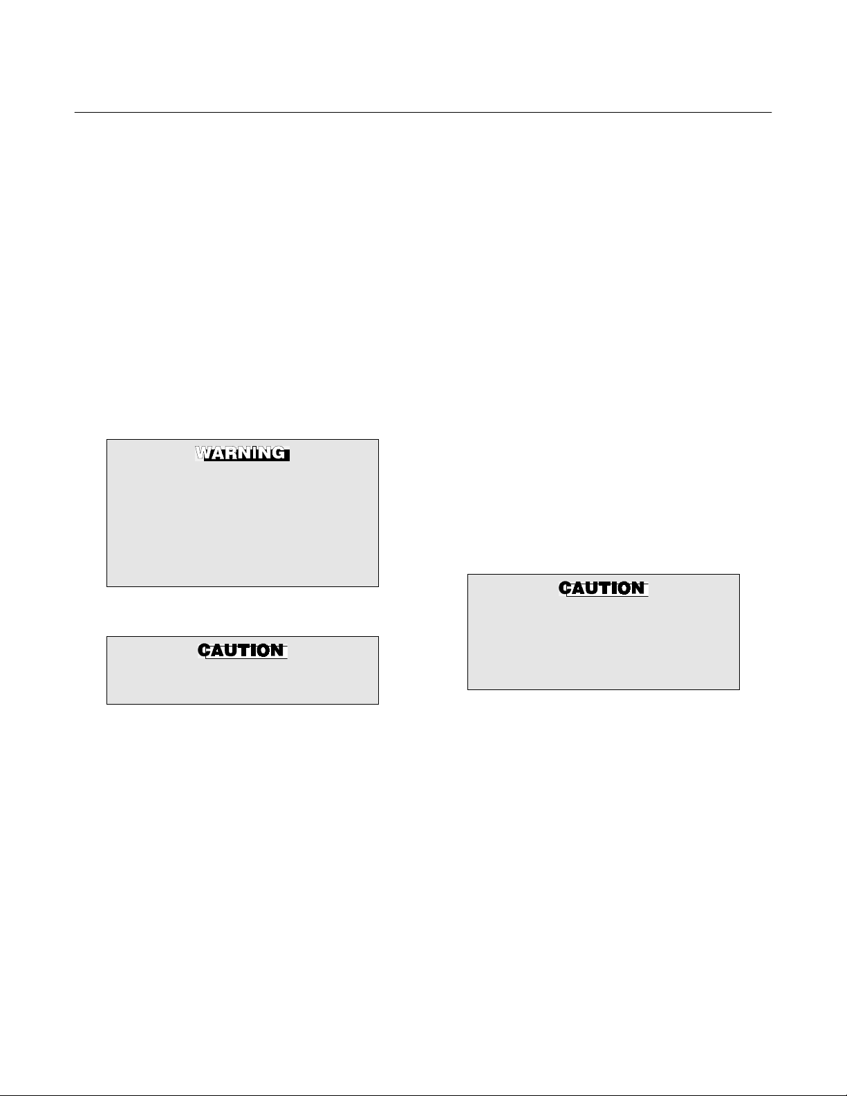
The following definitions apply to WARNINGS, CAUTIONS, and NOTES found throughout this
publication.
Instruction Manual
IB-106-4081 Rev. 1.2
September, 2002
PREFACE
DEFINITIONS
Highlights an operation or maintenance
procedure, practice, condition, statement, etc. If not strictly observed, could
result in injury, death, or long-term
health hazards of personnel.
Highlights an essential operating procedure,
condition, or statement.
: EARTH (GROUND) TERMINAL
: PROTECTIVE CONDUCTOR TERMINAL
: RISK OF ELECTRICAL SHOCK
: WARNING: REFER TO INSTRUCTION BULLETIN
NOTE TO USERS
Highlights an operation or maintenance
procedure, practice, condition, statement, etc. If not strictly observed, could
result in damage to or destruction of
equipment, or loss of effectiveness.
NOTE
The number in the lower right corner of each illustration in this publication is a manual illustration number. It is not a part number, and is not related to the illustration in any technical
manner.
Rosemount Analytical Inc. A Division of Emerson Process Management P-1
Page 10

Instruction Manual
IB-106-4081 Rev. 1.2
September, 2002
FOR THE WIRING AND INSTALLATION
The following safety instructions apply specifically to all EU member states. They should
be strictly adhered to in order to assure compliance with the Low Voltage Directive. NonEU states should also comply with the following unless superseded by local or National
Standards.
1. Adequate earth connections should be made to all earthing points, internal and external,
where provided.
2. After installation or troubleshooting, all safety covers and safety grounds must be replaced.
The integrity of all earth terminals must be maintained at all times.
3. Mains supply cords should comply with the requirements of IEC227 or IEC245.
Model 4081FG
IMPORTANT
SAFETY INSTRUCTIONS
OF THIS APPARATUS
4. All wiring shall be suitable for use in an ambient temperature of greater than 75°C.
5. All cable glands used should be of such internal dimensions as to provide adequate cable
anchorage.
6. To ensure safe operation of this equipment, connection to the mains supply should only be
made through a circuit breaker which will disconnect all circuits carrying conductors during a
fault situation. The circuit breaker may also include a mechanically operated isolating switch.
If not, then another means of disconnecting the equipment from the supply must be provided
and clearly marked as such. Circuit breakers or switches must comply with a recognized
standard such as IEC947. All wiring must conform with any local standards.
7. Where equipment or covers are marked with the symbol to the right, hazard-
ous voltages are likely to be present beneath. These covers should only be
removed when power is removed from the equipment — and then only by
trained service personnel.
8. Where equipment or covers are marked with the symbol to the right, there is a
danger from hot surfaces beneath. These covers should only be removed by
trained service personnel when power is removed from the equipment. Certain surfaces may remain hot to the touch.
9. Where equipment or covers are marked with the symbol to the right, refer to
the Operator Manual for instructions.
10. All graphical symbols used in this product are from one or more of the follow-
ing standards: EN61010-1, IEC417, and ISO3864.
P-2 Rosemount Analytical Inc. A Division of Emerson Process Management
Page 11

Model 4081FG
1
DESCRIPTION AND SPECIFICATIONS
Instruction Manual
IB-106-4081 Rev. 1.2
September, 2002
SECTION 1
1-1 COMPONENT CHECKLIST OF TYPICAL
SYSTEM (PACKAGE CONTENTS)
A typical Rosemount Two-Wire In Situ Oxygen
Analyzer should contain the items shown in
Figure 1-1. Record the part number, serial number, and order number for each component of
your system in the table located on the first
page of this manual. Also, use the product matrix in Table 1-1 to compare your order number
against your unit. The first part of the matrix defines the model. The last part defines the various options and features of the analyzer.
Ensure the features and options specified by
your order number are on or included with the
unit.
1-2 SYSTEM OVERVIEW
a. Scope
This Instruction Bulletin is designed to supply details needed to install, start up, operate, and maintain the Rosemount Two-Wire
In Situ Oxygen Analyzer. The analyzer consists of an oxygen probe and Model 4081
Transmitter. Integral signal conditioning
electronics outputs a digital F
fieldbus signal representing an O2 value. An
infrared remote control (IRC) allows access
to setup, calibration, and diagnostics. This
same information, plus additional details,
can be accessed via fieldbus digital
communications.
OUNDATION
OUNDATION
b. F
FOUNDATION fieldbus is an all digital, serial, two-way communication system that
inter-connects field equipment such as sensors, actuators, and controllers. Fieldbus is
a Local Area Network (LAN) for instruments
used in both process and manufacturing
automation with built-in capacity to distribute the control application across the network. The fieldbus environment is the base
level group of digital networks in the hierarchy of planet networks.
The fieldbus retains the desirable features
of the 4-20 mA analog system, including a
standardized physical interface to the wire,
bus powered devices on a single wire, and
intrinsic safety options, and enables additional capabilities, such as:
• Increased capabilities due to full digital
communications
• Reduced wiring and wire terminations
due to multiple devices on one set of
wires
• Increased selection of suppliers due to
inter-operability
• Reduced loading on control room
equipment with the distribution of some
control and input/output functions to field
devices
• Speed options for process control and
manufacturing applications
Fieldbus Technology
Rosemount Analytical Inc. A Division of Emerson Process Management Description and Specifications 1-1
Page 12
Instruction Manual
IB-106-4081 Rev. 1.2
September, 2002
Model 4081FG
1
7
6
2
3
5
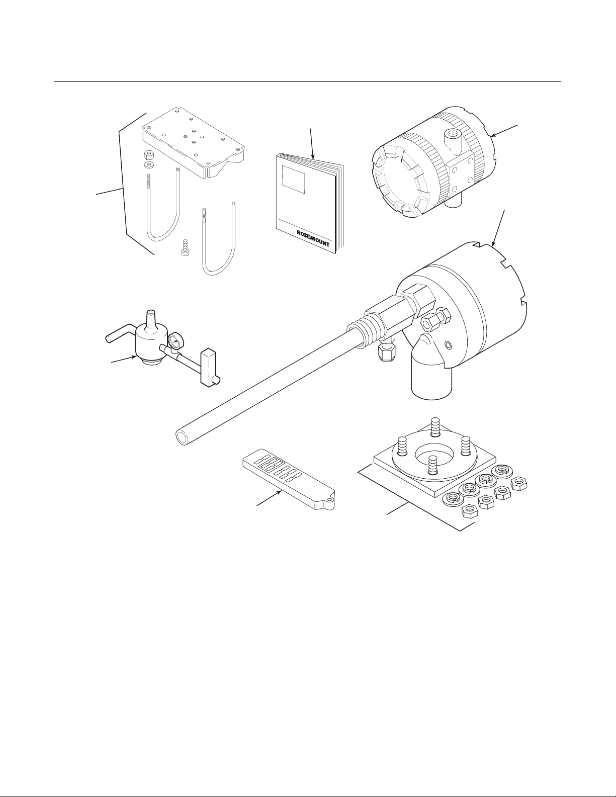
1. Instruction Bulletin
2. Model 4081 Transmitter
3. Oxygen Probe
4. Adapter Plate with Mounting Hardware
and Gasket (Optional)
5. Infrared Remote Control (IRC) (Optional)
6. Reference Air Set (Optional)
7. Pipe Mounting Kit (Optional)
4
29760001
Figure 1-1. Typical System Package
1-2 Description and Specifications Rosemount Analytical Inc. A Division of Emerson Process Management
Page 13
Instruction Manual
1
IB-106-4081 Rev. 1.2
Model 4081FG
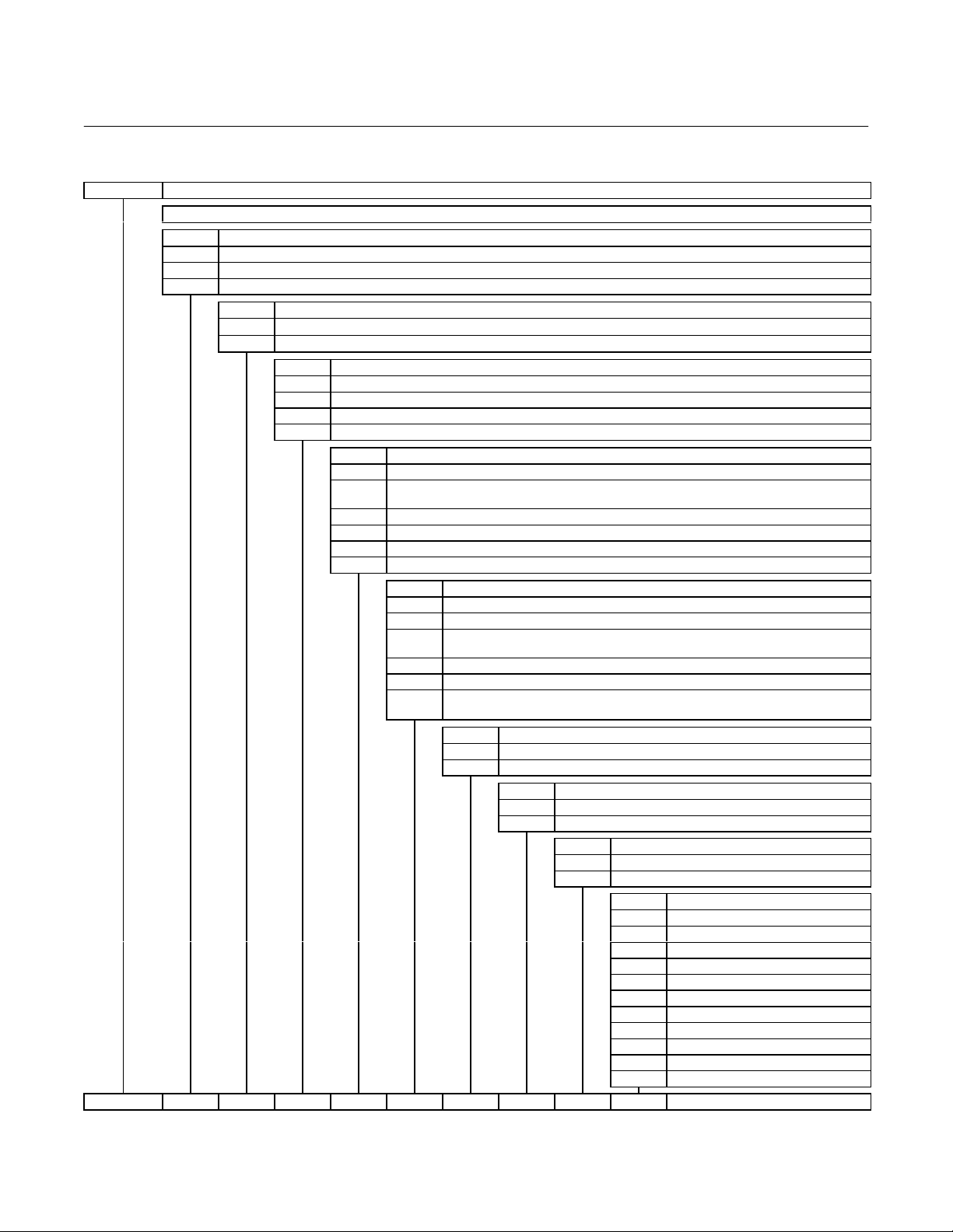
Table 1-1. Product Matrix
4081FG Model 4081FG In Situ Oxygen Analyzer with FOUNDATION Fieldbus Communications
Model 4081FG Oxygen Analyzer - Instruction Book
Code Sensing Probe Length
1 20 in. (508 mm) probe, 1/4 in. tube fittings
2 26 in. (660 mm) probe, 1/4 in. tube fittings
3 38 in. (965 mm) probe, 1/4 in. tube fittings
Code Probe Outer Tube Material - Maximum Operating Temperature
1 Alumina - 2912°F (1600°C) maximum - 1.25 NPT mounting
2 Inconel 600 - 1832°F (1000°C) maximum - 1.25 NPT mounting
Code Mounting Adapter - Stack Side
0 No adapter plate required uses 1.25 NPT (“0” must also be chosen under “Mounting Adapter” probe side)
1 New flanged installation - Square weld plate with studs (matches “Mounting Adapter” probe side)
2 Model 450 mounting (“4” must also be chosen under “Mounting Adapter” probe side)
3 Competitor's Mount (“5” must also be chosen under “Mounting Adapter” probe side)
Code Mounting Adapter - Probe Side
0 No adapter plate
1 ANSI 2 in. 150 lb flange to 1.25 NPT adapter
(6 in. dia. Flange, 4.75 in. BC with 4 x 0.75 in. dia. holes)
2 DIN to 1.25 NPT adapter (184 mm flange, 145 mm BC with 4 x 18 mm dia. holes)
3 JIS to 1.25 NPT adapter (155 mm flange, 130 mm BC with 4 x 13 mm dia. holes)
4 Model 450 to 1.25 NPT adapter
5 Competitor’s mounting flange
Code Electronics & Housing - Intrinsically Safe, NEMA 4X, IP65
1 4081 F
2 4081 F
3
4 4081 F
5 4081 F
6
4081FG2100111211 Example
OUNDATION
OUNDATION
OUNDATION
4081 F
Suite
OUNDATION
OUNDATION
4081 F
OUNDATION
Control Suite
Code Housing Mounting
0 Surface or wall mounting
1 1/2 to 2 in. pipe mounting
Fieldbus Electronics - CENELEC EEx ia IIC T5 with Control Suite
Fieldbus Electronics - CSA pending, with Control Suite
Fieldbus Electronics-FM Class I, Div. I, Groups B,C,D with Control
Fieldbus Electronics - CENELEC EEx ia IIC T5 without Control Suite
Fieldbus Electronics - CSA pending, without Control Suite
Fieldbus Electronics-FM Class I, Div. I, Groups B,C,D without
Code Communications
0 No remote control
1 Infrared Remote Control (IRC) (LCD display through cover)
Code Calibration Accessories
1 No hardware
2 Reference air flowmeters and pressure regulator
Code Armored Cable Length
00 No cable
11 20 ft (6 m)
12 40 ft (12 m)
13 60 ft (18 m)
14 80 ft (24 m)
15 100 ft (30 m)
16 150 ft (45 m)
17 200 ft (61 m)
18 300 ft (91 m)
19 400 ft (122 m)
20 500 ft (152 m)
September, 2002
Rosemount Analytical Inc. A Division of Emerson Process Management Description and Specifications 1-3
Page 14

Instruction Manual
IB-106-4081 Rev. 1.2
September, 2002
Table 1-2. Accessories
Part No. Description
1A99135H01 Armored cable, bulk, uncut, no connectors 100’ minimum.
1A99135H02 Unarmored cable, bulk, uncut, no connectors 100’ minimum.
Order as separate items.
Table 1-3. Mounting Adapter
Type Description
Plate with studs Bolt circle diameter, number and arrangement of studs, stud thread, stud height
above mounting plate.
Plate without studs Bolt circle diameter, number and arrangement of holes, thread, depth of stud
mounting plate with accessories.
Where possible specify SPS number; otherwise provide details of the existing mounting plate.
Model 4081FG
c. System Description
The Rosemount Two-Wire In Situ Oxygen
Analyzer is designed to measure the net
concentration of oxygen in an industrial process; i.e., the oxygen remaining after all fuels have been oxidized. The oxygen probe
is permanently positioned within an exhaust
duct or stack and performs its task without
the use of a sampling system. The Model
4081 Transmitter is mounted remotely and
conditions the oxygen probe outputs.
The equipment measures oxygen percentage by reading the voltage developed
across an electrochemical cell, which consists of a small yttria-stabilized, zirconia
disc. Both sides of the disc are coated with
porous metal electrodes. The millivolt output
voltage of the cell is given by the following
Nernst equation:
EMF = KT log
10(P1/P2
) + C
Where:
1. P
is the partial pressure of the oxygen
2
in the measured gas on one side of the
cell.
2. P
is the partial pressure of the oxygen
1
in the reference air on the opposite side
of the cell.
3. T is the absolute temperature.
4. C is the cell constant.
5. K is an arithmetic constant.
NOTE
For best results, use clean, dry, instrument air (20.95% oxygen) as the
reference air.
NOTE
The probe uses a Type B thermocouple to measure the cell temperature.
When the cell is at 550°C to 1600°C
(1022°F to 2912°F) and there are unequal
oxygen concentrations across the cell, oxygen ions will travel from the high oxygen
partial pressure side to the low oxygen partial pressure side of the cell. The resulting
logarithmic output voltage is approximately
50 mV per decade.
The output is proportional to the inverse
logarithm of the oxygen concentration.
Therefore, the output signal increases as
the oxygen concentration of the sample gas
decreases. This characteristic enables the
Rosemount Two-Wire In Situ Oxygen Analyzer to provide exceptional sensitivity and
accuracy at low oxygen concentrations.
1-4 Description and Specifications Rosemount Analytical Inc. A Division of Emerson Process Management
Page 15

Model 4081FG
1
Instruction Manual
IB-106-4081 Rev. 1.2
September, 2002
Oxygen analyzer equipment measures net
oxygen concentration in the presence of all
the products of combustion, including water
vapor. Therefore, it may be considered an
analysis on a “wet” basis. In comparison
with older methods, such as the portable
apparatus, which provides an analysis on a
“dry” gas basis, the “wet” analysis will, in
general, indicate a lower percentage of
oxygen. The difference will be proportional
to the water content of the sampled gas
stream.
d. System Configuration
The equipment discussed in this manual
consists of two major components: the oxygen probe and the Model 4081 Transmitter.
Oxygen probes are available in three length
options, providing in situ penetration appropriate to the size of the stack or duct. The
options on length are 20 in. (508 mm), 26
in. (660 mm), or 38 in. (965 mm).
The Model 4081 Transmitter is a two-wire
transmitter providing an output proportional
to the measured oxygen concentration. A
customer-supplied 24 VDC power source is
required to provide power to the electronics.
The transmitter accepts millivolt signals
generated by the probe and produces the
outputs to be used by other remotely connected devices. The output is a FOUNDATION fieldbus digital communication signal.
e. System Features
1. The cell output voltage and sensitivity
increase as the oxygen concentration
decreases.
2. High process temperatures eliminate
the need for external cell heating and
increase cell accuracy.
3. FOUNDATION fieldbus is standard.
4. Easy probe replacement due to the
lightweight, compact probe design.
5. Remote location of the Model 4081
Transmitter removes the electronics
from high temperature or corrosive
environments.
6. Power is supplied to the electronics
through the FOUNDATION fieldbus
digital signal line for intrinsic safety (IS)
purposes.
7. Infrared remote control (IRC) allows
inter-facing without exposing the
electronics.
8. An operator can operate and diagnostically troubleshoot the Two-Wire In
Situ Oxygen Analyzer in one of two
ways:
(a) Infrared Remote Control. The IRC
allows access to fault indication
menus on the Model 4081 Transmitter LCD display. Calibration can
be performed from the IRC keypad.
(b) FOUNDATION fieldbus Interface.
The transmitter’s output carries a
signal containing the oxygen level
encoded in digital format. This
digital output can also be used to
communicate with the oxygen
analyzer and access all of the oxygen analyzer status information.
9. Selected Distributed Control Systems The use of distributed control systems
requires input/output (I/O) hardware
and AMS Security codes are provided
(by infrared remote control) to prevent
unintended changes to analyzers adjacent to the one being accessed.
10. A calibration check procedure is provided to determine if the Rosemount
Two-Wire In Situ Oxygen Analyzer is
correctly measuring the net oxygen
concentration in the industrial process.
Rosemount Analytical Inc. A Division of Emerson Process Management Description and Specifications 1-5
Page 16

Instruction Manual
IB-106-4081 Rev. 1.2
September, 2002
Model 4081FG
f. Handling the Analyzer
The probe was specially packaged to prevent breakage due to handling. Do not remove the padding material from the probe
until immediately before installation.
It is important that printed circuit
boards and integrated circuits are
handled only when adequate antistatic
precautions have been taken to prevent possible equipment damage.
The oxygen probe is designed for industrial applications. Treat with care
to avoid physical damage. The probe
contains components made from ceramic, which are susceptible to shock
when mishandled. THE WARRANTY
DOES NOT COVER DAMAGE FROM
MISHANDLING.
temperatures, environmental considerations, convenience, and serviceability
Figure 1-2 shows the FOUNDATION Fieldbus communications interface. A typical
system installation is illustrated in Figure
1-3.
A source of instrument air is required at the
oxygen probe for reference air use. Since
the Two-Wire In Situ Oxygen Analyzer is
equipped with an in-place calibration feature, provisions should be made for connecting calibration check gas tanks to the
oxygen probe during calibration.
If the calibration check gas bottles are to be
permanently connected, a check valve is
required next to the calibration fittings on
the integral electronics.
This check valve is to prevent breathing of
calibration check gas line and subsequent
flue gas condensation and corrosion. The
check valve is in addition to the stop valve
in the calibration check gas kit.
g. System Considerations
Prior to installing your Rosemount Two-Wire
In Situ Oxygen Analyzer, make sure you
have all the components necessary to make
the system installation. Ensure all the components are properly integrated to make the
system functional.
After verifying that you have all the components, select mounting locations and determine how each component will be placed in
terms of available line voltage, ambient
NOTE
The electronics of the Model 4081
Transmitter is rated NEMA 4X (IP65)
and is capable of operating at temperatures up to 65°C (149°F).
NOTE
Retain the packaging in which the
Rosemount Two-Wire In Situ Oxygen
Analyzer arrived from the factory in
case any components are to be
shipped to another site. This packaging has been designed to protect the
product.
1-6 Description and Specifications Rosemount Analytical Inc. A Division of Emerson Process Management
Page 17

Model 4081FG
1
Instruction Manual
IB-106-4081 Rev. 1.2
September, 2002
TWO-WIRE IN SITU
OXYGEN ANALYZER
CALIBRATION CHECK
GAS LINE
Figure 1-2. Two-Wire In Situ Oxygen Analyzer Fieldbus Connections
GASES
STACK
REFERENCE
AIR LINE
OmV
2
SIGNAL
MODEL 4081
TRANSMITTER
TEMPERATURE
mV SIGNAL
DUCT
DIGITAL OUTPUT
FIELDBUS
(TWISTED PAIR)
INTRINSIC
SAFETY
BARRIER
(OPTIONAL)
FIELDBUS
COMPUTER TERMINAL
29760002
OXYGEN
PROBE
MODEL 4081
TRANSMITTER
OPTIONAL
ADAPTER
PLATE
FLOWMETER
FIELDBUS
DIGITAL SIGNAL
PRESSURE
REGULATOR
Figure 1-3. Typical System Installation
INSTRUMENT
AIR SUPPLY
(REFERENCE AIR)
29760003
Rosemount Analytical Inc. A Division of Emerson Process Management Description and Specifications 1-7
Page 18

Instruction Manual
IB-106-4081 Rev. 1.2
September, 2002
1-3 SPECIFICATIONS
Net O
Range ...................................................... 0 to 25% O2 Fully Field Selectable via the FOUNDATION
2
Fieldbus Interface
Lowest Limit................................................... 0.05% O
Highest Limit.................................................. 25.00% O
2
2
Accuracy.............................................................. ±1.5% of reading or 0.05% O2, whichever is greater
System Response to Calibration Check Gas...... Initial response in less than 3 seconds
T90 in less than 10 seconds
Probe
Lengths................................................................ 20 in. (508 mm)
26 in. (660 mm)
34.625 in. (880 mm)
Temperature Limits
Process Temperature Limits ......................... 550° to 1400°C (1022° to 2552°F)
Operation to 1600°C (2912°F) with reduced cell life.
Ambient ......................................................... -40° to 149°C (-40° to 300°F) Ambient
Mounting and Mounting Position......................... Vertical or Horizontal
Materials of Construction - Process Wetted Parts
Inner Probe ............................................. Zirconia
Outer Protection Tube............................. Alumina [1600°C (2912°F) limit]
Inconel 600 [1000°C (1832°F) limit]
Probe Junction Box................................. Cast aluminum
Speed of Installation/Withdrawal......................... 1 in. (25.4 mm) per minute
Hazardous Area Certification .............................. Intrinsically safe per EN50 014 (1977), clause 1.3
(pending)
Reference Air Requirement................................. 100 ml per minute (0.2 scfh) of clean, dry instrument air;
1/4 in. tube fittings
Calibration Check Gas Fittings............................ 1/4 in. tube fittings
Cabling ................................................................ Two twisted pairs, shielded
Electronics
Enclosure ............................................................ IP65 (NEMA 4X), weatherproof, and corrosion-resistant
Materials of Construction .................................... Low copper aluminum
Ambient Temperature Limits ............................... -20° to 65°C (-4° to 149°F)
Relative Humidity ................................................ 95% with covers sealed
Inputs (from O
Probe) ........................................ Two wires - O2 signal, Two wires - type B thermocouple
2
Output ................................................................ FOUNDATION Fieldbus digital signal
Fieldbus Logic Function Blocks
Two AI Blocks: Execution Rate .................... 75mS
PID Block: Execution Rate ........................... 150mS
Fieldbus Segment Power Consumption ............. 30mA max, 30VDC max
Hazardous Area Certification .............................. Cenelec EEx ia IIC T4 or T5(2) (pending)
NEC Class I Div.I Group B,C,D (pending)
Fisher-Rosemount has satisfied all obligations coming from the
European legislation to harmonize the product requirements in Europe.
Power Transient Protection ................................. IEC 801-4
Shipping Weight .................................................. 10 lbs (4.5 kg)
Infrared Remote Control
Power Requirements........................................... Three AAA batteries
Hazardous Area Certification .............................. Cenelec EEx ia IIC Class I, Div. I, Group A, B, C, D
(1)
Thermocouple and O2 probe cell are both unpowered, developing a millivolt emf, and are considered a “simple apparatus” by certifying agencies.
(2)
Dependent on ambient temperature limits.
Model 4081FG
(1)
1-8 Description and Specifications Rosemount Analytical Inc. A Division of Emerson Process Management
Page 19
Model 4081FG
2
Instruction Manual
IB-106-4081 Rev. 1.2
September, 2002
SECTION 2
INSTALLATION
2-1 PRE-INSTALLATION
a. Inspect
Carefully inspect the shipping container for
any evidence of damage. If the container is
damaged, notify the carrier immediately.
b. Packing List
Confirm all items shown on the packing list
are present. Notify Rosemount Analytical
immediately if items are missing.
Before installing this equipment, read
the “Safety instructions for the wiring
and installation of this apparatus” at
the front of this Instruction Bulletin.
Failure to follow the safety instructions could result in serious injury or
death.
2-2 MECHANICAL INSTALLATION
Avoid installation locations near
steam soot blowers.
the process gas temperature falls within
a range of 550° to 1600°C (1022° to
2912°F). Figure 2-1 provides mechanical installation references.
2. Check the flue or stack for holes and
air leakage. The presence of this condition will substantially affect the accuracy of the oxygen reading. Therefore,
either make the necessary repairs or
install the probe up-stream of any
leakage.
3. Ensure the area is clear of internal and
external obstructions that will interfere
with installation and maintenance access to the probe. Allow adequate
clearance for probe removal (Figure
2-1).
b. Installing Oxygen Probe
The probe was specially packaged to
prevent breakage due to handling. Do
not remove the padding material from
the probe until immediately before installation.
1. Ensure all components are available to
a. Locating Oxygen Probe
1. The location of the oxygen probe in the
stack or flue is important for maximum
accuracy in the oxygen analyzing process. The probe must be positioned so
the gas it measures is representative of
the process. Best results are normally
obtained if the probe is positioned near
the center of the duct (40-60% insertion).
Longer ducts may require several analyzers since the O
stratification. A point too near the wall of
the duct, or the inside radius of a bend,
may not provide a representative sample
because of the very low flow conditions.
The sensing point should be selected so
Rosemount Analytical Inc. A Division of Emerson Process Management Installation 2-1
can vary due to
2
Leave the probe inner protective cover
in place until installation. This is required to protect the ceramic cell during movement.
install the probe.
NOTE
2. If using an optional adapter plate
(Figure 2-2) or an optional mounting
flange (Figure 2-3), weld or bolt the
component onto the duct. The through
hole in the stack or duct wall and refractory material must be 2 in. (50.8
mm) diameter, minimum.
Page 20

Instruction Manual
IB-106-4081 Rev. 1.2
September, 2002
Model 4081FG
Figure 2-1. Probe Installation Details
A
B
C
NOTE: DIMENSIONS ARE
IN INCHES WITH
MILLIMETERS IN
PARENTHESES.
DIMENSION
“B” THREAD 0.625-11 M-16x2 M-12x1.75
“C” DIA. 4.75 (121) 5.71 (145) 5.12 (130)
METAL WALL
STACK OR DUCT
A
WELD OR BOLT ADAPTER
PLATE TO STACK OR DUCT.
JOINT MUST BE AIR TIGHT.
PLATE DIMENSIONS
ANSI
4512C34G01
“A” 6.00 (153) 7.5 (191) 6.50 (165)
2.50 (63.5)
MIN. DIA.
JOINT MUST
BE AIR TIGHT
DIN
4512C36G01
MASONRY WALL
STACK
3.00 SCHEDULE 40
PIPE SLEEVE
SUPPLIED BY CUSTOMER
JIS
4512C35G01
WELD PIPE TO
ADAPTER PLATE
3.50 (89)
O.D. REF
29750002
Figure 2-2. Optional Adapter Plate
2-2 Installation Rosemount Analytical Inc. A Division of Emerson Process Management
Page 21

Model 4081FG
2
Instruction Manual
IB-106-4081 Rev. 1.2
September, 2002
TAP 1.25 NPT
B
A
C
FLANGE DIMENSIONS
ANSI
DIMENSION
“A” DIA. 6.00 (153) 7.28 (185) 6.10 (155) 9.00 (229)
“B” DIA. 0.75 (20) 0.71 (18) 0.59 (15) 0.50 (13)
“C” DIA. 4.75 (121) 5.71 (145) 5.12 (130) 7.68 (195)
5R10158H01
DIN
5R10158H02
0.50 (12.7)
NOTE: DIMENSIONS ARE IN
INCHES WITH MILLIMETERS
IN PARENTHESES.
JIS
5R10158H03
MODEL 450
5R10158H04
29750003
Figure 2-3. Optional Probe Mounting Flange
3. If the optional adapter plates are not
used, a 2 in. NPT, schedule 40, pipe
nipple (Figure 2-4) should be welded to
the stack or duct wall.
When a 2 in. NPT to 1.25 NPT adapter
is threaded to the welded pipe nipple,
the adapter provides the pipe threads
needed for the probe’s process fitting.
Rosemount Analytical Inc. A Division of Emerson Process Management Installation 2-3
Page 22

Instruction Manual
IB-106-4081 Rev. 1.2
September, 2002
Model 4081FG
STACK OR DUCT
METAL WALL
WELD PIPE TO
METAL WALL
2.0 IN. (51 mm)
MIN. DIA.
REFRACTORY
SCHEDULE 40
STACK OR DUCT
METAL WALL
ADAPTER
2 IN. NPT
PIPE
1.25 NPT
CUSTOMER
SUPPLIED
ADAPTER
INSULATE IF EXPOSED
TO AMBIENT WEATHER
CONDITIONS
2 IN. NPT
SCHEDULE 40
PIPE
CALIBRATION
CHECK
GAS LINE
REFERENCE
AIR LINE
SYSTEM
CABLE
29750004
Figure 2-4. Horizontal Probe Installation
2-4 Installation Rosemount Analytical Inc. A Division of Emerson Process Management
Page 23

Model 4081FG
2
REFRACTORY
STACK OR
DUCT METAL
PROBE LENGTH
A
WAL L
1.5 + A
Instruction Manual
IB-106-4081 Rev. 1.2
September, 2002
DIMENSION A -- 1-5/8, 2-1/2, 3, OR
4 IN. 1.25 NPT SCHEDULE 40
PIPE NIPPLE
2 IN., 1.25 NPT
PIPE COUPLING
29750005
Figure 2-5. Adjusting Probe Insertion Depth
Rosemount Analytical Inc. A Division of Emerson Process Management Installation 2-5
Page 24

Instruction Manual
IB-106-4081 Rev. 1.2
September, 2002
Model 4081FG
4. Where high particulate or slag is in the
flue gas stream, it may be desirable to
inset the probe in the refractory as
shown in Figure 2-5. Use pipe couplings and nipples to adjust the probe
insertion depth.
5. Use rags or other material to seal
around the probe during insertion. This
prevents hot gases from escaping or
cold air from entering the stack or duct.
6. Initially insert the probe to a depth of 3
in. (76.2 mm) or ½ the depth of the
stack or duct refractory, whichever is
greater.
After initial insertion, do not insert the
probe at a rate exceeding 1 in. per minute (25.4 mm per minute) or damage
to the probe may result due to thermal
shock.
the probe. Ensure the electrical conduit
is routed below the level of the terminal
block housing. This drip loop minimizes
the possibility that moisture will accumulate in the housing.
9. If insulation was removed to access the
duct work for probe mounting, make
sure the insulation is replaced afterward. See Figure 2-4.
If the ducts will be washed down during outage, MAKE SURE to power
down the probes and remove them
from the wash area.
c. Locating Model 4081 Transmitter
1. Ensure the Model 4081 Transmitter is
easily accessible for maintenance and
service and for using the infrared remote control (if applicable).
7. After initial insertion, insert the probe at
a rate of 1 in. (25.4 mm) per minute
until the probe is fully inserted.
8. Install anti-seize compound on the pipe
threads and screw the probe into the
process flange or adapter.
NOTE
Use anti-seize compound on threads
to ease future removal of probe.
The electrical conduit port should be
facing down for a horizontal probe installation. See Figure 2-4. In vertical
probe installations, orient the probe so
the system cable drops vertically from
Do not allow the temperature of the
Model 4081 Transmitter to exceed
65°C (149°F) or damage to the unit
may result.
2. The ambient temperature of the transmitter housing must not exceed 65°C
(149°F). Locate the electronics in an
area where temperature extremes, vibration, and electromagnetic and radio
frequency interference are minimal.
3. Locate the Model 4081 Transmitter
within 150 ft (45.7 m) of the oxygen
probe due to wiring and signal
considerations.
2-6 Installation Rosemount Analytical Inc. A Division of Emerson Process Management
Page 25

Model 4081FG
2
Instruction Manual
IB-106-4081 Rev. 1.2
September, 2002
d. Installing Model 4081 Transmitter
1. Ensure all components are available to
install the Model 4081 Transmitter.
2. Choose a method or location to mount
the transmitter.
(a) Flat Surface Mounting. The trans-
mitter may be mounted on a flat
COVER
LOCK
CIRCUIT
END
6.32
(160.5)
6.35
(161.3)
TERMINAL
END
THREADED CAP
(2 PLACES)
surface using the threaded mounting holes located on the bottom of
the transmitter housing. Refer to
Figure 2-6 for installation references.
(b) Pipe Mounting. An optional pipe
mounting bracket is available for
this type of installation. Refer to
Figure 2-7 for installation
references.
TERMINAL BLOCK (TB)
TERMINAL END
CAP OMITTED
FOR CLARITY
(THIS VIEW)
1.32
(33.5)
O-RING
(2 PLACES)
NOTE: DIMENSIONS ARE IN INCHES
WITH MILLIMETERS IN
PARENTHESES.
3.68
(93.5)
Figure 2-6. Flat Surface Mounting Dimensional Information
3/4-14 NPT
(2 PLACES)
SURFACE
BY OTHERS
0.839
(21.31)
FLAT SURFACE MOUNTING
PAD HOLE PATTERN
1/4-20 THREADS
(4 PLACES)
0.839
(21.31)
26020003
Rosemount Analytical Inc. A Division of Emerson Process Management Installation 2-7
Page 26

Instruction Manual
IB-106-4081 Rev. 1.2
September, 2002
6.35
(161.3)
COVER LOCK
6.9
(175.3)
Model 4081FG
TERMINAL
BLOCK (TB)
CIRCUIT
6.32
(160.5)
1.00
(25.4)
0.375 (9.525) DIA.
(4 MOUNTING
HOLES)
1.405
(35.687)
2.81
(71.374)
END
1.32
(33.5)
C
L
3.87
(98.3)
3.25
(82.55)
7.5
(190.5)
6.5
(165.1)
C
L
TERMINAL
END
3/4 -14 NPT
2 PLACES
3/4-14 FNPT
(2 PLACES)
5/16-18 NUT
4.00
(101.6)
TERMINAL END CAP
OMITTED FOR CLARITY
IN THIS VIEW.
2 IN. PIPE/WALL
MOUNTING BRACKET
(OPTION)
U-BOLT
(2 PLACES)
%
1/4-20 THREADS
BRACKET HOLE PATTERN
FOR WALL MOUNTING
NOTE:
DIMENSIONS ARE IN INCHES WITH
MILLIMETERS IN PARENTHESES.
*SCREWS FURNISHED WITH
Figure 2-7. Pipe Mounting Dimensional Information
5/16 WASHER
U-BOLT
MOUNTING KIT ONLY. NOT
FURNISHED WITH
ANALYZER/TRANSMITTER.
BOTTOM VIEW
1/4-20 SCREW*
29760016
2-8 Installation Rosemount Analytical Inc. A Division of Emerson Process Management
Page 27

Model 4081FG
2
Instruction Manual
IB-106-4081 Rev. 1.2
September, 2002
3. For correct viewing orientation, the display may be changed 90 degrees, using the following procedure:
(a) Refer to Figure 2-8. Loosen the
cover lock screw until the cover
lock is disengaged from the
knurled surface on the threaded
circuit end cap.
(b) Remove the circuit end cap.
(c) Remove the three screws retaining
the display board in place.
(d) Lift and rotate the display board 90
degrees either way.
(e) Reposition the display board on
the standoffs. Install and tighten all
three screws.
(f) Install the circuit end cap and
tighten the cover lock screw to secure the cover lock in place.
CIRCUIT
END CAP
SCREW
COVER LOCK
SCREW
DISPLAY
BOARD
90
O
90
O
Figure 2-8. Display Positioning Assembly
HOUSING
29760004
Rosemount Analytical Inc. A Division of Emerson Process Management Installation 2-9
Page 28
Instruction Manual
IB-106-4081 Rev. 1.2
September, 2002
Model 4081FG
2-3 ELECTRICAL INSTALLATION
All wiring must conform to local and national
codes.
Disconnect and lock out power before
connecting the unit to the power
supply.
Install all protective equipment covers
and safety ground leads after installation. Failure to install covers and
ground leads could result in serious
injury or death.
To meet the Safety Requirements of
IEC 1010 (EC requirement), and ensure
safe operation of this equipment, connection to the main electrical power
supply must be made through a circuit
breaker (min 10 A) which will disconnect all current-carrying conductors
during a fault situation. This circuit
breaker should also include a mechanically operated isolating switch. If
not, then another external means of
disconnecting the supply from the
equipment should be located close by.
Circuit breakers or switches must
comply with a recognized standard
such as IEC 947.
a. General
The power supply and signal wiring should
be shielded. Also, make sure the signal
wiring is grounded at the Model 4081
Transmitter end only. Do not ground the
signal loop at more than one point. Twisted
pairs are recommended. Ground the transmitter housing to an earth ground to prevent
unwanted electromagnetic interference
(EMI) or radio frequency interference (RFI).
NOTE
For optimum EMI/RFI immunity, shield
the FOUNDATION fieldbus signal cable and enclose in an earth grounded
metal conduit.
Never run signal or sensor wiring in
the same conduit, or open tray, with
power cables. Keep signal or sensor
wiring at least 12 in. (0.3 m) away from
other electrical equipment and 6.5 ft (2
m) from heavy electrical equipment.
It is necessary to prevent moisture from
entering the Model 4081 Transmitter housing. The use of weather-tight cable glands is
required. If conduit is used, plug and seal
connections on the transmitter housing to
prevent moisture accumulation in the terminal side of the housing.
Moisture accumulation in the transmitter housing can affect its performance
and may void its warranty.
b. Oxygen Probe Signal Connections
1. Two signals represent the O
and the cell temperature. The probe
provides these values to the Model
4081 Transmitter for processing and
signal conditioning.
2. Wiring connections for the probe are
shown in Figure 2-9.
value
2
2-10 Installation Rosemount Analytical Inc. A Division of Emerson Process Management
Page 29

Model 4081FG
2
TERMINAL
BLOCK
CONDUIT
FACTORY-INSTALLED
JUMPER
TERMINAL
BLOCK (TB1)
PROBE
CABLE
SHIELD
GROUND
4
3
12
Instruction Manual
IB-106-4081 Rev. 1.2
September, 2002
CELL - (WH)
THERMOCOUPLE - (RD)
CELL + (BK)
7
6
5
THERMOCOUPLE + (GY)
EARTH
GROUND
11
12
TERMINALS
FIELDBUS
13
DIGITAL (-)
14
15
FIELDBUS
16
DIGITAL (+)
8
9
10
THERMOCOUPLE + (GY)
THERMOCOUPLE - (RD)
CELL - (WH)
CELL + (BK)
26020004
Figure 2-9. Oxygen Probe Terminal Block
c. Model 4081 Transmitter and F
OUNDATION
Fieldbus Signal Connections
1. Two signals representing the O
value
2
and the cell temperature are supplied
to the Model 4081 Transmitter from the
oxygen probe.
2. Wiring connections for the Model 4081
Transmitter are shown in Figure 2-10.
NOTE
The ground arrangement shown in
Figure 2-10 limits the amount of noise
introduced into the electronics.
3. Connect wire shields to terminal 1.
Connect earth ground as shown.
CELL AND
THERMOCOUPLE
CONDUITS
NOTE:
RUN CELL AND THERMOCOUPLE SIGNALS IN
SEPARATE CONDUIT FROM .FIELDBUS
Figure 2-10. Model 4081 Transmitter
Terminal Block
2-4 PNEUMATIC INSTALLATION
a. General
Reference air is required for O
and calibration check gas is required during
a calibration check. Refer to Figure 2-11 for
the gas connections on the oxygen probe.
b. Reference Air Package
After the oxygen probe is installed, connect
the reference air set. Install the reference
air set according to Figure 2-12.
c. Instrument Air (Reference Air)
Instrument air is required for reference. Use
10 psig (68.95 kPa gage) minimum,
FIELDBUS
DIGITAL
29760005
calculation,
2
Rosemount Analytical Inc. A Division of Emerson Process Management Installation 2-11
Page 30

Instruction Manual
IB-106-4081 Rev. 1.2
September, 2002
225 psig (1551.38 kPa gage) at 0.2 scfh
(100 ml/min.); less than 40 parts-per-million
total hydrocarbons. Regulator outlet pressure should be set at 5 psi (35 kPa).
d. Calibration Check Gas
Two calibration check gas concentrations
are used with the Two-Wire In Situ Oxygen
Analyzer: Low Gas - 0.4% O
- 8% O
Do not use 100% nitrogen. See Figure 2-11
for the probe connections. Set both calibration check gases at the same flow rate:
5 scfh (2.5 L/min).
, each with the balance in nitrogen.
2
and High Gas
2
Model 4081FG
1/4 TUBE FITTING
(REFERENCE AIR PORT)
1/4 TUBE FITTING
(CALIBRATION CHECK
Figure 2-11. Oxygen Probe Gas Connections
GAS PORT)
REFERENCE
AIR VENT
26020006
4.81 (122.17)
FLOW SET
POINT KNOB
0.125-27 NPT FEMALE
OUTLET CONNECTION
1
2
1.19
(30.22)
DRAIN VALVE
OUTLET
10.0
(254)
REF
3.12 (79.25) MAX
3
(SUPPLIED BY CUSTOMER)
1/4” TUBE
2.250 (57.15)
2.0
(50.80)
1.50
(38.10)
1 FLOWMETER 0.2-2.0 SCFH 771B635H08
2 2" PRESSURE GAGE 0-15 PSIG 275431-006
3 COMBINATION FILTER-REG. 0-30 PSIG 4505C21G01
TO PROBE
NOTE: DIMENSIONS ARE IN INCHES WITH
0.25-18 NPT FEMALE
INLET CONNECTION
2 MOUNTING HOLES
3.19 (81.03) LG
THROUGH BODY FOR
0.312 (7.92) DIA BOLTS
REF AIR SET
263C152G05
MILLIMETERS IN PARENTHESES.
8.50
(215.90)
MAX
INSTRUMENT
AIR SUPPLY
10-225 PSIG
MAX PRESSURE
SCHEMATIC HOOKUP FOR REFERENCE AIR SUPPLY ON OXYGEN PROBE.
26020034
Figure 2-12. Air Set, Plant Air Connection
2-12 Installation Rosemount Analytical Inc. A Division of Emerson Process Management
Page 31

Model 4081FG
3
Install all protective equipment covers
and safety ground leads before
equipment startup. Failure to install
covers and ground leads could result
in serious injury or death.
3-1 GENERAL
a. Verify Mechanical Installation
SECTION 3
STARTUP
Instruction Manual
IB-106-4081 Rev. 1.2
September, 2002
play should look similar to Figure 3-1. The
display will now track the O
and cell temperature.
concentration
2
O CONCENTRATION
2
Ensure the Oxygen Analyzer is installed
correctly. See paragraph 2-2 for mechanical
installation information.
b. Verify Terminal Block Wiring
Ensure the wiring of both the oxygen probe
terminal block and Model 4081 Transmitter
terminal block is correct. Refer to paragraph
2-3 for electrical installation and wiring
information.
3-2 POWER UP
a. General
The Two-Wire In Situ Oxygen Analyzer displays the current oxygen reading on the
LCD face of the Model 4081 Transmitter.
The O
concentration and cell temperature
2
are displayed as shown in Figure 3-1. This
and other in-formation may also be accessed using the FOUNDATION Fieldbus.
b. Startup Display
When the probe is first inserted into the
stack, some time is required until minimum
operating temperatures [550°C (1022°F)]
are reached. Some time is also required for
the electronics to reach an operating state.
Therefore, when the unit is first powered up,
a faulted operation display as shown in
Figure 3-2 may be displayed by the transmitter until the probe operating temperatures are reached and the electronics are
working properly (approximately 5 minutes).
c. Operating Display
CELL
TEMPERATURE
Figure 3-1. Normal Operation Display
%
29760006
%
29760007
After the probe has reached operating tem-
Figure 3-2. Faulted Operation Display
peratures, the Model 4081 Transmitter dis-
Rosemount Analytical Inc. A Division of Emerson Process Management Startup 3-1
Page 32

Instruction Manual
IB-106-4081 Rev. 1.2
September, 2002
Model 4081FG
3-3 REESTABLISHING PROPER CALIBRATION
CHECK GAS FLOW RATE
The calibration check gas flow must be enough
to ensure no combustion flue gases mix with the
calibration check gases and only clean, good
calibration check gas surrounds the cell without
expending excess gas (Figure 3-3). Monitor the
O
concentration using an IRC or F
2
OUNDATION
fieldbus. Set the calibration check gas flow rate
as follows:
NOTE
Only set the calibration check gas flow
rate at startup. It is not necessary to
perform this procedure for each calibration check.
FLUE GAS
PROTECTIVE
TUBE
CELL
a. Adjust the calibration check gas flow to 5
scfh (2.5 L/min) to ensure the cell is surrounded by calibration check gas. Due to
the cooling effect of the gas, the cell temperature will decrease slightly, causing the
O
concentration to drop. Once the elec-
2
tronics compensates for this effect, the O
concentration will stabilize.
b. Next, slowly reduce the calibration check
gas flow until the O
concentration changes,
2
which indicates that the calibration check
and flue gases are mixing. Increase the flow
rate until this effect is eliminated.
STACK OR DUCT
METAL WALL
2
CALIBRATION
GAS
Figure 3-3. Proper Calibration Check Gas Flow Rate
REFRACTORY
CHECK GAS LINE
CALIBRATION
REFERENCE
AIR LINE
26020062
3-2 Startup Rosemount Analytical Inc. A Division of Emerson Process Management
Page 33

Model 4081FG
4
Instruction Manual
IB-106-4081 Rev. 1.2
September, 2002
SECTION 4
OPERATION
4-1 GENERAL
a. Overview
This section explains the operator controls
and displays of the Two-Wire In Situ Oxygen Analyzer. The use of the Infrared Remote Control (IRC) and the Model 4081
Transmitter Liquid Crystal Display (LCD) are
described in detail.
CIRCUIT
END
b. Display
The Model 4081 Transmitter LCD displays
the O
concentration and cell temperature
2
during normal operation (see Figure 4-1).
The LCD will also display fault conditions
when they occur. To interact with the transmitter, use the IRC and navigate through a
series of menus displayed on the LCD.
TERMINAL
END
MODEL 4081 TRANSMITTER
ELECTRONICS HOUSING
%
Figure 4-1. Normal Operation Display
29760008
Rosemount Analytical Inc. A Division of Emerson Process Management Operation 4-1
Page 34

Instruction Manual
IB-106-4081 Rev. 1.2
September, 2002
ON STARTUP
RESET
OR ON
FROM ANY
SCREEN
PROCESS DISPLAY
NORMAL
OPERATION
EXIT
ON FROM
ANY SCREEN
EXIT
WITHOUT
EXPLICITY
STATED
Model 4081FG
1 - USER ENTERS DISPLAY
ANALYZER CODE
2 - USER ENTERS ANALYZER
ACCESS CODE
CAL
NEXT
PROG
2
CODE
1
DISPLAY
CODE
CELL T HI
RESET MAX
CELL T
SET O2 FILTER
TIME
SET HI BOTTLE
O2
SET LO BOTTLE
O2
555 ENTER
NEXT
NEXT
NEXT
NEXT
NEXT
PROCESS DISPLAY
FAULTED
OPERATION
EXIT
PROGRAM
MENU
DIAG
SHOW FAULT IN MANUAL?
T/C mV ACCEPT HIGH O2
O2 CELL mV ACCEPT LOW O2
CELL
IMPEDANCE
PREVIOUS
SLOPE
PREVIOUS
CONSTANT
MAX CELL T
ENTER
NEXT ENTER
NEXT NEXT
NEXT NEXT
NEXT
NEXT
EXIT
EXIT
DIAGNOSTICS
NEXT
NEXT
FAULT
(IF PRESENT)
FAULT
(IF PRESENT)
MENU
PURGING
NEXT
SLOPE
NEXT
CONSTANT
RESET OR EXIT
CALCHECK
MENU
SET CODE
NEXT
SW VER
NEXT
UNIT SER #
NEXT
SW BUILD
NUMBER
NEXT
SW BUILD DATE
29760009
Figure 4-2. Model 4081 Transmitter Menu Tree
4-2 Maintenance and Service Rosemount Analytical Inc. A Division of Emerson Process Management
Page 35

Model 4081FG
4
c. Menu Tree
The screens that can be displayed are
shown in the menu tree of Figure 4-2.
These screens are displayed on the LCD
and are accessed using the IRC keypad.
d. Navigation
The IRC in Figure 4-3 is used to interact
with the Model 4081 Transmitter and navigate through the screens on the LCD.
Instruction Manual
IB-106-4081 Rev. 1.2
September, 2002
RESET HOLD
ENTERCAL
1. Hold the IRC within 6 ft (1.8 m) of the
Model 4081 Transmitter and within 15
degrees from the centerline of the
transmitter LCD. The amount of ambient light may also affect IRC
performance.
NOTE
The LCD may react slowly to IRC
commands. Allow sufficient time between key presses to avoid undesired
or repeated commands from accumulating in the command queue.
2. Use the keys on the IRC to navigate
through the menu screens. Refer to
Figure 4-3. General usage is as
follows:
(a) RESET. Returns to the PROCESS
DISPLAY screen at the top of the
menu tree. Any non-entered number in the exited state will be ignored, and the previous data will
be used.
(b) HOLD. Not used.
(c) Left/Right Arrow. Moves left and
right among editable digits on the
display.
(d) Up/Down Arrow. Increases or de-
creases the value of the currently
selected digit on the display.
PROG
DIAG EXIT
REMOTE CONTROL
ROSEMOUNT
NEXT
MODEL 3081
FISHER-ROSEMOUNT
29760010
Figure 4-3. Infrared Remote Control (IRC)
(e) CAL. Accesses the CALCHECK
MENU branch of the menu tree.
Only works from the PROCESS
DISPLAY screen.
(f) PROG. Accesses the PROGRAM
MENU branch of the menu tree.
Only works from the PROCESS
DISPLAY screen.
(g) DIAG. Accesses the DIAGNOS-
TICS MENU branch of the menu
tree. Only works from the PROCESS DISPLAY screen.
Rosemount Analytical Inc. A Division of Emerson Process Management Operation 4-3
Page 36

Instruction Manual
IB-106-4081 Rev. 1.2
September, 2002
Model 4081FG
(h) ENTER. Initiates the editing proc-
ess and causes the most significant digit of the edited item to start
flashing. Also processes the entry
so the previous value updates to
the new value entered using the
arrow keys. Failure to press ENTER before exiting a screen will
cancel the input value and revert to
the previous value.
(i) NEXT. Accesses the next user
screen as shown in the menu tree.
Any non-entered number in the exited state will be ignored, and the
previous data will be used.
(j) EXIT. Exits from sub-branches of
the menu tree where an exit option
is explicitly shown. Otherwise, returns to the PROCESS DISPLAY
screen at the top of the menu tree.
Any non-entered number in the exited state will be ignored, and the
previous data will be used.
4-2 PROGRAM MENU
a. CODE
Refer to Figure 4-4. After pressing the
PROG key, this screen will display. Use this
screen to identify a specific analyzer in a
process to prevent accessing an adjacent
analyzer when using the IRC.
Press ENTER to begin editing. At this point,
you can either specify the analyzer by its
access code or view its code if it is unknown.
1. To gain further access to the screens
in the PROGRAM MENU branch, enter the correct three-digit analyzer access code using the arrow keys and
press ENTER. If security is disabled,
this screen does not appear and the
system displays the FAULT VAL
screen.
2. If the analyzer access code is unknown, enter 555 and press ENTER to
access the DISPLAY CODE screen. In
that screen, you will be able to view the
analyzer access code.
The PROGRAM MENU branch of the menu
tree allows you to program and edit some process parameters, faults, outputs, and security
codes. To access this branch of the menu tree,
press the PROG key on the IRC when in the
PROCESS DISPLAY screen (Normal or
Faulted). You must enter the analyzer code to
gain further access to the screens in this
branch. Each screen in this branch is accessed
sequentially using the NEXT key. Refer to
Figure 4-2 during the following menu and
screen descriptions.
NOTE
To edit a screen value, press ENTER
to access the data field. Use the left
and right arrow keys to move among
the digits in the data field. Note that
the editable position will be flashing.
To change the value of a digit, use the
up and down arrow keys to increase or
decrease the value. When finished editing, press ENTER to accept the
value. To go to the next screen in the
menu, press NEXT.
O CONCENTRATION
2
%
Figure 4-4. CODE
ANALYZER
ACCESS CODE
OR SECURITY
ACCESS CODE
26020009
4-4 Maintenance and Service Rosemount Analytical Inc. A Division of Emerson Process Management
Page 37

Model 4081FG
4
Instruction Manual
IB-106-4081 Rev. 1.2
September, 2002
b. DISPLAY CODE
Refer to Figure 4-5. This screen is accessible from the CODE screen by entering 555
and pressing ENTER. The DISPLAY CODE
screen identifies the analyzer access code
so you can return to the CODE screen and
enter the code as described in paragraph 42a. To return to the Process Display screen,
press EXIT.
O CONCENTRATION
2
%
c. CELL T HI
Refer to Figure 4-6. Use this screen to set
the value of the upper cell temperature fault
condition. This value is the maximum allowed cell temperature before a fault condition is indicated. Press ENTER to begin
editing. Use the arrow keys to select and
change the value. The value must be between 550° and 1600°C. Press ENTER to
accept the value. Pressing NEXT displays
the RESET MAX CELL T screen.
O CONCENTRATION
2
%
ACCESS CODE
Figure 4-5. DISPLAY CODE
ANALYZER
26020047
UPPER CELL
TEMPERATURE
FAULT VALUE
26020012
Figure 4-6. CELL T HI
Rosemount Analytical Inc. A Division of Emerson Process Management Operation 4-5
Page 38

Instruction Manual
IB-106-4081 Rev. 1.2
September, 2002
Model 4081FG
d. RESET MAX CELL T
Refer to Figure 4-7. The transmitter tracks
the maximum cell temperature obtained.
Use this screen to reset the maximum cell
temperature attained value to the current
cell temperature. Press ENTER to begin
editing. Use the arrow keys to select and
change the value (Y/N). Then, press ENTER to accept the value. Pressing NEXT
displays the SET O
FILTER TIME screen.
2
O CONCENTRATION
2
%
e. SET O
FILTER TIME
2
Refer to Figure 4-8. In some applications, it
is beneficial to dampen the raw O
2
coming from the cell. Use this screen to
enter the amount of time it will take the O
to reach 90% of the new reading. Press
ENTER to begin editing. Use the arrow keys
to select and change the screen value to
the O
filter value (in seconds). Enter a
2
value between 0 and 300 seconds and
press ENTER to accept the value. Press
NEXT to access the SET HI BOTTLE O
screen.
O CONCENTRATION
2
%
signal
2
2
Y/N (TO RESET
MAXIMUM CELL
TEMPERATURE)
Figure 4-7. RESET MAX CELL T
26020013
O FILTER
2
VALUE (IN SECONDS)
Figure 4-8. SET O2 FILTER TIME
26020048
4-6 Maintenance and Service Rosemount Analytical Inc. A Division of Emerson Process Management
Page 39

Model 4081FG
4
Instruction Manual
IB-106-4081 Rev. 1.2
September, 2002
f. SET HI BOTTLE O
2
Refer to Figure 4-9. Use this screen to
identify, within the electronics, the percentage of O
used as the high calibration check
2
gas. Press ENTER to begin editing. Use the
arrow keys to select and change the screen
value to the O
percentage of the high cali-
2
bration check gas. Press ENTER to accept
the value. Press NEXT to display the SET
LO BOTTLE O
screen.
2
O CONCENTRATION
2
%
g. SET LO BOTTLE O
2
Refer to Figure 4-10. Use this screen to
identify, within the electronics, the percentage of O
used as the low calibration check
2
gas. Press ENTER to begin editing. Use the
arrow keys to select and change the screen
value to the O
percentage of the low cali-
2
bration check gas. Press ENTER to accept
the value. Press NEXT to display the SET
CODE screen.
O CONCENTRATION
2
%
HIGH CALIBRATION
CHECK GAS O
PERCENTAGE
Figure 4-9. SET HI BOTTLE O
LOW CALIBRATION
2
26020049
2
Figure 4-10. SET LO BOTTLE O
CHECK GAS O
PERCENTAGE
26020050
2
2
Rosemount Analytical Inc. A Division of Emerson Process Management Operation 4-7
Page 40

Instruction Manual
IB-106-4081 Rev. 1.2
September, 2002
Figure 4-11. SET CODE
h. SET CODE
Refer to Figure 4-11. Use this screen to set
the security code for the Model 4081
Transmitter. Press ENTER to begin editing.
Use the arrow keys to select and change
the value. Select any value between 000
and 999, excluding 000 and 555. Code 000
indicates that no code is set. Code 555 accesses the DISPLAY CODE screen. Press
ENTER to accept the value. Pressing NEXT
returns to the CELL T HI screen at the beginning of the PROGRAM MENU.
i. Model 4081 Transmitter Parameters
O CONCENTRATION
2
%
26020016
Model 4081FG
4-3 DIAGNOSTICS MENU
The DIAGNOSTICS MENU branch of the menu
tree allows you to examine outputs, current
faults, and unit information. None of the items in
the DIAGNOSTICS MENU are editable. This
branch of the menu tree may be accessed by
pressing DIAG on the IRC when in the PROCESS DISPLAY screen (Normal or Faulted).
Each screen in this branch is accessed sequentially by pressing NEXT. Refer to Figure 4-2
during the following menu and screen descriptions.
a. SHOW FAULT
Refer to Figure 4-12. After pressing DIAG,
this screen displays. Pressing ENTER accesses a screen displaying the current fault
(if any). If more than one fault exists, and
you are in the fault screen, the display cycles through all existing faults. Information
on the fault screens can be found in Section
6, TROUBLESHOOTING. Press EXIT to
return from this fault sub-menu and press
NEXT to access the T/C mV screen.
%
Table 4-1 lists the range and default value
of operator-adjustable variables used by the
Model 4081 Transmitter. These variables
may all be changed from the PROGRAM
MENU screens.
Table 4-1. Model 4081 Transmitter Parameters
Parameter Range Default
Upper Range Limit 2.0-25.0% 10.0%
Upper Cell Temp. Fault
Value
Analyzer Access Code 000-999
650-1600°C 1600°C
000
(excluding
(no code)
26020017
Figure 4-12. SHOW FAULT
000 and 555)
4-8 Maintenance and Service Rosemount Analytical Inc. A Division of Emerson Process Management
Page 41

Model 4081FG
4
Instruction Manual
IB-106-4081 Rev. 1.2
September, 2002
b. T/C mV
Refer to Figure 4-13. Use this screen to examine the cell thermocouple mV output.
Three decimal places are displayed.
Pressing NEXT accesses the O
CELL mV
2
screen.
%
THERMOCOUPLE mV
26020018
c. O
CELL mV
2
Refer to Figure 4-14. Use this screen to examine the O
CELL mV output. Pressing
2
NEXT accesses the CELL IMPEDANCE
screen.
%
O CELL mV
2
Figure 4-14. O2 CELL mV
26020019
Figure 4-13. T/C mV
Rosemount Analytical Inc. A Division of Emerson Process Management Operation 4-9
Page 42

Instruction Manual
IB-106-4081 Rev. 1.2
September, 2002
Model 4081FG
IMPEDANCE STATUS
Figure 4-15. CELL IMPEDANCE
d. CELL IMPEDANCE
O CONCENTRATION
2
%
O CELL
2
26020020
temperature before checking cell impedance. If checked before the cell
reaches operating temperature [550°C
(1022°F)], this screen displays a fail
indication.
e. PREVIOUS SLOPE
Refer to Figure 4-16. Use this screen to examine the slope calculated from the most
recent calibration check. The slope is the
amount of cell voltage generated for a given
O
value. For each calibration check, record
2
the slope over the life of the probe. Tracking
the slope will indicate if the probe is degrading. Press NEXT to access the PREVIOUS CONSTANT screen.
O CONCENTRATION
2
%
Refer to Figure 4-15. Use this screen to examine the O
CELL IMPEDANCE status.
2
GOOD indicates the cell is operating normally. WARN indicates the cell has degraded but is still operational. HI indicates
that the cell has degraded but is still operational; however, failure will occur soon.
Pressing NEXT accesses the PREVIOUS
SLOPE screen.
NOTE
Temperature influences cell impedance. Wait until the cell is at operating
CALCHECK CELL
SLOPE VALUE
26020052
Figure 4-16. PREVIOUS SLOPE
4-10 Maintenance and Service Rosemount Analytical Inc. A Division of Emerson Process Management
Page 43

Model 4081FG
4
Instruction Manual
IB-106-4081 Rev. 1.2
September, 2002
f. PREVIOUS CONSTANT
Refer to Figure 4-17. Use this screen to examine the cell zero constant calculated from
the most recent calibration check. The constant represents the voltage generated by
the cell when no difference exists between
the amount of O
on the reference and pro-
2
cess sides of the cell. Press NEXT to access the MAX CELL T screen.
O CONCENTRATION
2
%
g. MAX CELL T
Refer to Figure 4-18. Use this screen to examine the maximum temperature attained
by the O
cell. This value can be reset un-
2
der the PROGRAM MENU. Pressing
NEXT accesses the SW VER screen.
%
CALCHECK CELL
CONSTANT VALUE
Figure 4-17. PREVIOUS CONSTANT
26020053
CELL
TEMPERATURE
MAXIMUM
26020021
Figure 4-18. MAX CELL T
Rosemount Analytical Inc. A Division of Emerson Process Management Operation 4-11
Page 44

Instruction Manual
IB-106-4081 Rev. 1.2
September, 2002
Model 4081FG
h. SW VER
Use this screen to see the software version
number for the Model 4081 Transmitter.
Pressing NEXT accesses the UNIT SER #
screen.
i. UNIT SER #
Use this screen to see the unit serial number for the Model 4081 Transmitter. Pressing NEXT accesses the SW BUILD
NUMBER screen.
j. SW BUILD NUMBER
Use this screen to see the software build
number for the Model 4081 Transmitter.
Pressing NEXT accesses the SW BUILD
DATE screen.
k. SW BUILD DATE
Use this screen to see the software build
date for the Model 4081 Transmitter.
Pressing NEXT returns to the beginning of
the DIAGNOSTICS MENU branch (the
SHOW FAULT screen).
a. IN MANUAL? Refer to Figure 4-19.
Failure to remove the analyzer from
automatic control loops prior to performing this procedure may result in a
dangerous operating condition.
If the O2 output value is used in any automatic process control loops, the loop must
be placed in manual before beginning a
calibration check.
Once the analyzer is removed from any
automatic control loops, press ENTER to
edit the screen. Use the arrow keys to select Y (yes) and press ENTER to process
the selection and to display the ACCEPT
HIGH O
screen.
2
O CONCENTRATION
2
%
4-4 CALCHECK MENU
The CALCHECK MENU branch of the menu
tree (Figure 4-2) allows you to perform a calibration check of the analyzer. Before performing
a calibration check, ensure the high calibration
check gas and low calibration check gas O
percentages are entered into the electronics via
the PROGRAM MENU. To set these values,
refer to paragraphs 4-2f and 4-2g.
Once these values are set, access the CALCHECK MENU branch by pressing CAL on the
IRC when in the PROCESS DISPLAY screen
(Normal or Faulted). Each screen in this branch
identifies a process step in the calibration check
procedure. The first screen in the sequence is
the IN MANUAL? screen.
2
Y/N (FOR USER
RESPONSE)
26020054
Figure 4-19. IN MANUAL?
4-12 Maintenance and Service Rosemount Analytical Inc. A Division of Emerson Process Management
Page 45

Model 4081FG
4
Instruction Manual
IB-106-4081 Rev. 1.2
September, 2002
O CONCENTRATION
2
%
%
HIGH CALIBRATION
CHECK GAS O VALUE
Figure 4-20. ACCEPT HIGH O
ACCEPT HIGH O
b.
2
2
Refer to Figure 4-20. After pressing ENTER
to begin the calibration check, the high calibration check gas starts to flow. After waiting approximately three minutes for the
displayed O
value to settle, press NEXT to
2
accept the high calibration check gas reading and apply the low calibration check gas.
The next screen to display is the ACCEPT
LOW O
screen.
2
2
26020055
O CONCENTRATION
2
%
%
LOW CALIBRATION
CHECK GAS O VALUE
Figure 4-21. ACCEPT LOW O
c. ACCEPT LOW O
2
2
Refer to Figure 4-21. Once the low calibration check gas is applied, wait approximately three minutes for the displayed O
value to settle. Once the value settles,
press NEXT to accept the reading and to
display the PURGING screen.
2
26020056
2
Rosemount Analytical Inc. A Division of Emerson Process Management Operation 4-13
Page 46

Instruction Manual
IB-106-4081 Rev. 1.2
September, 2002
Figure 4-22. PURGING
d. PURGING
The PURGING screen provides an opportunity for the O
cess gas concentration prior to exiting the
calibration procedure. Once the displayed
oxygen concentration has returned to the
process gas value, press the NEXT button
to display the SLOPE screen.
e. SLOPE
O CONCENTRATION
2
%
29760017
reading to return to the pro-
2
Model 4081FG
O CONCENTRATION
2
%
CALCHECK CELL
SLOPE VALUE
Figure 4-23. SLOPE
f. CONSTANT
Refer to Figure 4-24. Use this screen to
examine the cell zero constant calculated
from the current calibration check. The constant represents the voltage generated by
the cell when no difference exists between
the amount of O
cess sides of the cell. Note this value for
comparison against future calibration
checks. Press RESET or EXIT to return to
the PROCESS DISPLAY screen.
on the reference and pro-
2
26020057
Refer to Figure 4-23. Use this screen to examine the slope calculated from current
O CONCENTRATION
2
calibration check. The slope is the amount
of cell voltage generated for a given O
2
value. After each calibration check, record
the slope over the life of the probe. Tracking
the slope will indicate if the probe is de-
%
grading. Press NEXT to access the CONSTANT screen.
CALCHECK CELL
CONSTANT VALUE
26020058
Figure 4-24. CONSTANT
4-14 Maintenance and Service Rosemount Analytical Inc. A Division of Emerson Process Management
Page 47

Model 4081FG
4
4-5 SIMULATE SWITCH
Instruction Manual
IB-106-4081 Rev. 1.2
September, 2002
The Model 4081FG is equipped with a simulate
function. Located on the fieldbus board is a
switch that controls the simulate enable status
of the analyzer. Refer to Figure 4-25. To allow
the analyzer to be placed in simulation mode,
place the switch in the ON position.
This must be done while the instrument is powered on. The simulate function will not actuate
unless it sees the transition from OFF to ON.
To remove the device from the simulate mode,
place the switch in the OFF position, or cycle
power to the analyzer. Note that this switch
does not actually place the analyzer in the
simulate mode, it only allows the simulate mode
to be enabled via fieldbus.
4-6 SECURITY SWITCH
The Model 4081FG contains a security function
which prevents parameter from being changed
via fieldbus. Refer to Figure 4-25. To enable
the security feature, set the security switch located on the fieldbus board to ON, then enable
security in the resource block.
SIMULATE
SWITCH (3)
ON OFF
E4.000
40
K
123
ON
SECURITY
SWITCH (2)
ON OFF
Figure 4-25. Simulate and Security Switch
Positions
29760020
Rosemount Analytical Inc. A Division of Emerson Process Management Operation 4-15
Page 48

Instruction Manual
IB-106-4081 Rev. 1.2
September, 2002
Model 4081FG
1. Housing
2. O-ring
3. Lockwasher
4. Screw
5. Terminal End Cap
6. Terminal Block
7. Ground Screw
8. Washer
1
9. O-ring
10. PC Board Stack (CPU, Analog, and
FOUNDATION Fieldbus Boards)
11. Display Board
12. Screw
13. Circuit End Cap
14. Screw
15. Cover Lock
2
7
8
4
3
5
6
9
10
15
13
12
14
STANDOFF
11
RIBBON
CABLE
F
OUNDATION
FIELDBUS
BOARD
Figure 5-1. Two-Wire In Situ Oxygen Analyzer Exploded View
STANDOFF
ANALOG
BOARD
CPU BOARD
29760014
5-0 Maintenance and Service Rosemount Analytical Inc. A Division of Emerson Process Management
Page 49

Model 4081FG
5
MAINTENANCE AND SERVICE
Install all protective equipment covers
and safety ground leads after equipment repair or service. Failure to install covers and ground leads could
result in serious injury or death.
Disconnect and lock out power before
working on any electrical components.
Instruction Manual
IB-106-4081 Rev. 1.2
September, 2002
SECTION 5
6. Reposition display board (11) on the
standoffs. Rotate the display board 90
degrees either way as desired.
7. Install and tighten all three screws (12).
8. Install circuit end cap (13).
9. Tighten cover lock screw (14) until
cover lock (15) engages knurled surface of circuit end cap (13).
b. PC Board Stack Replacement
5-1 MODEL 4081 ELECTRONICS
REPLACEMENT
Before replacing any electronic components,
verify that the power to the Model 4081 Transmitter is removed. Refer to Table 8-1 for replacement part numbers.
a. Display Board Replacement
Use the following procedure to replace display board (11, Figure 5-1).
1. Loosen screw (14) until cover lock (15)
disengages from the knurled surface of
circuit end cap (13).
2. Remove circuit end cap (13).
3. Remove three screws (12) retaining
the electronics in place.
4. Lift display board (11) and disconnect
the ribbon cable connector between
the display board and the CPU board
of PC board stack (10).
5. Using a replacement display board,
connect the ribbon cable connector
between the display board and the
CPU board of PC board stack (10).
Ensure the cable connector is fully
seated.
PC board stack (10, Figure 5-1) is composed of the CPU board and the analog
board. Use the following procedure to replace these boards as a set.
1. Loosen cover lock screw (14) until
cover lock (15) disengages from the
knurled surface of circuit end cap (13).
2. Remove circuit end cap (13). Remove
three screws (12).
3. Lift display board (11) and disconnect
the ribbon cable connector between
the display board and the CPU board
of PC board stack (10).
4. Lift the CPU board from housing (1) by
the standoffs.
5. Remove two screws (4) and lockwashers (3). Lift terminal block (6) until the
analog board is unplugged from the
terminal board.
6. Reinstall terminal block (6), lockwashers (3), and screws (4).
7. Lift the analog board from housing (1)
by the standoffs.
Rosemount Analytical Inc. A Division of Emerson Process Management Maintenance and Service 5-1
Page 50

Instruction Manual
IB-106-4081 Rev. 1.2
September, 2002
Model 4081FG
8. Install replacement PC board stack
(10) into housing (1). Carefully seat the
analog board onto housing pins. Press
firmly on the CPU board standoffs to
ensure good contact.
9. Connect the ribbon cable connector
between display board (11) and the
CPU board of PC board stack (10).
Ensure the cable connector is fully
seated.
10. Reposition display board (11) on the
standoffs. Rotate the display board 90
degrees either way as desired.
11. Install and tighten all three screws (12)
and circuit end cap (13).
12. Tighten cover lock screw (14) until
cover lock (15) engages knurled surface of circuit end cap (13).
Use heat resistant gloves and clothing
when removing the probe. The probe
can be as hot as 1600°°°°C (2912°°°°F). This
can cause severe burns.
5-2 OXYGEN PROBE REPLACEMENT
The oxygen probe is designed with ceramic
materials to provide maximum life at elevated
temperatures and is not rebuildable. The condition of the sensing cell can be determined periodically by two methods:
• Note the cell impedance at the electronics.
When the impedance displays a warning indication (WARN), increase the frequency of
impedance readings. A cell with a sustained
high impedance indication (HI) indicates a
probe that is beyond its useful life.
• Conduct a calibration check. Follow the
prompts provided by the electronics through
the process of flowing two calibration check
gases of known values. Record the generated slope and constant values.
Probe replacement may be conducted online as
long as the process in which the probe is
mounted is operating at a negative, or slightly
positive, pressure. Refer to Section 6, TROUBLESHOOTING, for more information.
Do not install or remove probes from a
process where pressures are more
than a few inches of H2O positive
pressure. Hot gases may escape from
the stack and cause severe personal
injury.
Do not insert or withdraw a probe into
or out of a hot process faster than 1 in.
(25.4 mm) per minute or instrument
damage from thermal shock may occur.
Also, ash, slag, or other materials can
build up on the probe body in some
applications. If this buildup is causing
difficulty when withdrawing the probe,
DO NOT FORCE. Rotate the probe
back and forth to attempt to loosen the
material on the probe body. Or, wait
until the process cools down and access the buildup from inside the furnace.
5-2 Maintenance and Service Rosemount Analytical Inc. A Division of Emerson Process Management
Page 51

Model 4081FG
5
Refer to Table 8-1 for replacement probe part
numbers. Before replacing the probe, verify that
the reference air and calibration check gas lines
are turned off and disconnected from the probe.
a. Remove the end cap of the probe to expose
the terminal block.
b. Refer to Figure 5-2. Disconnect the four
wires (two oxygen signal wires and two
thermocouple wires) from the terminal
block.
c. Disconnect the reference air and the cali-
bration check gas lines.
d. Unscrew the probe from the stack and re-
move.
e. Using a replacement probe, refer to para-
graph 2-2c for mechanical installation instructions.
Instruction Manual
IB-106-4081 Rev. 1.2
September, 2002
TERMINAL
BLOCK
CONDUIT
f. Refer to paragraph 2-3b for electrical in-
stallation instructions.
g. Refer to paragraph 2-4 for reference air and
calibration check gas installation instructions.
THERMOCOUPLE + (GY)
THERMOCOUPLE - (RD)
CELL - (WH)
CELL + (BK)
26020004
Figure 5-2. Oxygen Probe Terminal Block
Rosemount Analytical Inc. A Division of Emerson Process Management Maintenance and Service 5-3
Page 52

Instruction Manual
IB-106-4081 Rev. 1.2
September, 2002
Model 4081FG
5-4 Maintenance and Service Rosemount Analytical Inc. A Division of Emerson Process Management
Page 53

Model 4081FG
6
Instruction Manual
IB-106-4081 Rev. 1.2
September, 2002
SECTION 6
TROUBLESHOOTING
Life of the probe is negatively impacted by:
Install all protective equipment covers
and safety ground leads after troubleshooting. Failure to install covers and
ground leads could result in serious
injury or death.
6-1 GENERAL
This troubleshooting section describes how to
identify and isolate faults that may develop in
the Two-Wire In Situ Oxygen Analyzer.
6-2 PROBE LIFE
The zirconium oxide technology for measuring
oxygen is very stable and should provide accurate service for several years.
50
40
• Continued operation at elevated tempera-
tures above 1300°C (2372°F).
• Operation in processes that contain high
levels of sulfur, SO
, or other acidic com-
2
pounds.
Operating conditions with simultaneously high
levels of SO
and low levels of O2 are particu-
2
larly damaging.
The health and accuracy of a given cell is
closely related to the resistance, or impedance,
of the cell. Figure 6-1 illustrates that the amount
of output from a cell for a given O
value (repre-
2
sented as slope) will remain very stable to the
point where cell impedance increases to approximately 100 ohms.
30
20
SLOPE (mV/Dec)
10
0
NORMAL
OPERATIONAL
CONDITIONS
48.0<S<51 mV/Dec
DETERIORATED PERFORMANCE,
SLOW RESPONSE,
HIGH MEASUREMENT ERROR
45.0<S<48 mV/Dec
IMPEDANCE,
DETERIORATED PERFORMANCE,
SLOW RESPONSE,
HIGH MEASUREMENT ERROR.
CONDUCT FREQUENT CALIBRATION CHECKS.
S<45 mV/Dec
Ω
26020059
Figure 6-1. Slope vs. Impedance
Rosemount Analytical Inc. A Division of Emerson Process Management Troubleshooting 6-1
Page 54

Instruction Manual
IB-106-4081 Rev. 1.2
September, 2002
Model 4081FG
500
400
90
SPEED OF RESPONSE (t ), sec
300
200
100
0
AIR TO 0.4% O
0.4% O TO AIR
2
Figure 6-2. Speed of Response
Frequently conduct calibration checks to look for
the following conditions:
• Continued degradation of cell slope.
• Sluggish response. (Note how long it takes
the cell to respond to the application of calibration check gases.) See Figure 6-2.
2
IMPEDANCE,
Ω
O
reading is present. When the error is cor-
2
26020060
rected, the screen will return to a normal operation display unless another error exists.
The slope will be valid only for the process temperature at which the calibration check gases
%
are flowed, so no adjustments to the electronics
are made as a result of a calibration check.
Note that cells exposed to temperatures above
1300°C (2372°F) may lose the ability to measure accurately and respond quickly when returned to the lowest end of the operating
temperature range [550°C (1022°F)].
6-3 FAULT INDICATIONS
The fault conditions for the Two-Wire In Situ
Oxygen Analyzer will be indicated by the faulted
29760012
operation display as shown in Figure 6-3. This
screen displays when a fault that invalidates the
6-2 Troubleshooting Rosemount Analytical Inc. A Division of Emerson Process Management
Figure 6-3. Faulted Operation Display
Page 55

Model 4081FG
6
Instruction Manual
IB-106-4081 Rev. 1.2
September, 2002
6-4 IDENTIFYING AND CORRECTING FAULT
INDICATIONS
A fault in the operation of the Two-Wire In Situ
Oxygen Analyzer is indicated by the faulted operation display. If no faults exist, the display will
indicate NONE. Information on the current fault
is found under the DIAGNOSTICS MENU as
detailed in Section 4, OPERATION.
The following paragraphs describe the faults,
possible causes, and corrective actions. Refer
to Figure 6-4 as needed for test points and wiring information.
NOTE
Allow adequate time for the oxygen
probe to reach its operating temperature [approximately 500°°°°C (932°°°°F)] before investigating a fault. The SHOW
FAULTS screen of the DIAGNOSTICS
menu will indicate a fault until the unit
reaches operating temperature.
NOTE
The probe uses a Type B thermocouple to measure the cell temperature. A
Type B thermocouple output table may
be useful for troubleshooting.
CELL - (WH)
THERMOCOUPLE
FACTORY-INSTALLED
JUMPER
TERMINAL
BLOCK (TB1)
PROBE
CABLE
SHIELD
GROUND
CELL AND
THERMOCOUPLE
4
3
12
CELL + (BK)
5
- (RD)
THERMOCOUPLE
+ (GY)
8
9
7
6
10
11
12
EARTH
GROUND
TERMINALS
FIELDBUS
13
DIGITAL (- )
14
15
FIELDBUS
16
DIGITAL (+)
FIELDBUS
DIGITAL
29760013
Figure 6-4. Model 4081 Transmitter Terminal Block
Rosemount Analytical Inc. A Division of Emerson Process Management Troubleshooting 6-3
Page 56

Instruction Manual
IB-106-4081 Rev. 1.2
September, 2002
Figure 6-5. Fault 1, Open Thermocouple
a. Fault 1, Open Thermocouple
The thermocouple connection is open. The
fault displays as shown in Figure 6-5.
1. Refer to Figure 6-4 and check the
thermocouple wiring connections at
terminals 8 and 10. Ensure the wires
are properly connected.
2. Remove power. Disconnect the thermocouple wires (gray and red) from
terminals 10 and 8. Measure the continuity across the gray and red thermocouple leads. The measurement
should read approximately 1-2 ohms.
Larger values indicate the thermocouple is open.
3. If the thermocouple is open, replace
the oxygen probe per paragraph 5-2.
Model 4081FG
%
%
26020025
Figure 6-6. Fault 2, Reversed Thermocouple
26020024
b. Fault 2, Reversed Thermocouple Active
The thermocouple connections are reversed. The fault displays as shown in
Figure 6-6.
1. Allow adequate time for the oxygen
probe to reach operating temperatures.
Probe temperatures below approximately 500°C (932°F) may result in this
fault.
2. Refer to Figure 6-4. Check the gray (to
terminal 10) and red (to terminal 8)
wires for the proper placement.
3. Using a multimeter, measure between
terminals 8(-) and 10(+). If the reading
is negative, the thermocouple wiring is
re-versed. Rewire as necessary.
4. If the wiring is correct and the probe is
at operating temperature, then the
transmitter electronics are bad. Replace the PC board stack assembly per
paragraph 5-1.
6-4 Troubleshooting Rosemount Analytical Inc. A Division of Emerson Process Management
Page 57

Model 4081FG
6
Instruction Manual
IB-106-4081 Rev. 1.2
September, 2002
%
26020026
Figure 6-7. Fault 3, Shorted Thermocouple
c. Fault 3, Shorted Thermocouple
The thermocouple connections are shorted.
The fault displays as shown in Figure 6-7.
1. Allow adequate time for the oxygen
probe to reach operating temperatures.
Probe temperatures below approximately 500°C (932°F) may result in this
fault.
%
26020027
Figure 6-8. Fault 4, High Probe Temperature
d. Fault 4, High Probe Temperature
The probe’s temperature has exceeded the
maximum cell temperature setpoint. The
fault displays as shown in Figure 6-8.
1. If the probe temperature exceeds the
maximum cell temperature setpoint,
the FOUNDATION fieldbus signal will
indicate a questionable O
level.
2
2. Refer to Figure 6-4. Using a multimeter, measure between terminals 8(-)
and 10(+).
2. Verify that the upper cell temperature
setpoint is configured as desired under
the PROGRAM MENU (see Section 4,
OPERATION).
3. If the multimeter reading, in voltage
mode, is between -0.5 and +0.5 mV,
the thermocouple is shorted.
4. If the thermocouple is shorted, replace
the oxygen probe per paragraph 5-2.
5. If the thermocouple is not shorted, then
replace the PC board stack assembly
per paragraph 5-1.
Rosemount Analytical Inc. A Division of Emerson Process Management Troubleshooting 6-5
Page 58

Instruction Manual
IB-106-4081 Rev. 1.2
September, 2002
Model 4081FG
Figure 6-9. Fault 5, O2 Cell Open
e. Fault 5, O
The O
Cell Open
2
cell connection is open. The fault
2
displays as shown in Figure 6-9.
1. Allow adequate time for the oxygen
probe to reach operating temperatures.
Probe temperatures below approximately 500°C (932°F) may result in this
fault.
2. Refer to Figure 6-4 and check the O
cell wiring connections at terminals 7
and 8. Ensure the wires are properly
connected.
NOTE
%
26020028
%
26020029
Figure 6-10. Fault 6, Cell Impedance Too High
f. Fault 6, Cell Impedance Too High
The O
cell impedance has exceeded 100
2
ohms. The fault displays as shown in Figure
6-10.
1. This fault is usually indicated in conjunction with Fault 5, Cell Open. Correcting Fault 5 should correct Fault 6.
2. If Fault 6 appears independently, the
2
cell has degraded beyond specification.
3. If the O
cell has become too old, re-
2
place the oxygen probe per paragraph
5-2.
Check the cell output voltage at the
probe terminals -- not at the electronics.
3. Apply low calibration check gas (0.4%
O
). Measure the cell output from the
2
O
cell wires at the probe terminal
2
block. The cell output should be 100
±20 mV. If no voltage can be measured, the cell is open.
4. If the O
cell is open, replace the oxy-
2
gen probe per paragraph 5-2.
6-6 Troubleshooting Rosemount Analytical Inc. A Division of Emerson Process Management
Page 59

Model 4081FG
6
Instruction Manual
IB-106-4081 Rev. 1.2
September, 2002
%
Figure 6-11. Fault 7, Reversed O2 Cell
26020030
g. Fault 7, Reversed O
The O
cell connections are reversed. The
2
Cell
2
fault displays as shown in Figure 6-11.
1. Refer to Figure 6-4. Check the black
(to terminal 7) and white (to terminal 8)
wires for the proper placement. Rewire
if necessary.
2. Apply the low calibration check gas
(0.4% O
).
2
3. Using a multimeter, measure between
terminals 7(+) and 8(-). If the cell output reading is negative, the O
wiring is reversed.
4. If the wiring is correct, check if the multimeter reading is the same as the
reading shown on the O
agnostics screen (see Section 4, OPERATION).
5. If the reading is different, the transmitter electronics are faulty. Replace the
PC board stack assembly per paragraph 5-1.
cell
2
CELL mV di-
2
Rosemount Analytical Inc. A Division of Emerson Process Management Troubleshooting 6-7
Page 60

Instruction Manual
IB-106-4081 Rev. 1.2
September, 2002
Model 4081FG
6-8 Troubleshooting Rosemount Analytical Inc. A Division of Emerson Process Management
Page 61

Model 4081FG
7
Instruction Manual
IB-106-4081 Rev. 1.2
September, 2002
SECTION 7
RETURN OF MATERIAL
7-1 If factory repair of defective equipment is re-
quired, proceed as follows:
a. Secure a return authorization number from
a Rosemount Analytical Sales Office or representative before returning the equipment.
Equipment must be returned with complete
identification in accordance with Rosemount
instructions or it will not be accepted.
In no event will Rosemount be responsible
for equipment returned without proper
authorization and identification.
b. Carefully pack defective unit in a sturdy box
with sufficient shock absorbing material to
ensure that no additional damage will occur
during shipping.
c. In a cover letter, describe completely:
1. The symptoms from which it was determined that the equipment is faulty.
2. The environment in which the equipment has been operating (housing,
weather, vibration, dust, etc.).
3. Site from which equipment was removed.
4. Whether warranty or nonwarranty
service is requested.
5. Complete shipping instructions for return of equipment.
6. Reference the return authorization
number.
d. Enclose a cover letter and purchase order
and ship the defective equipment according
to instructions provided in Rosemount Return Authorization, prepaid, to:
Rosemount Analytical Inc.
RMR Department
1201 N. Main Street
Orrville, Ohio 44667
If warranty service is requested, the defective unit will be carefully inspected and
tested at the factory. If failure was due to
conditions listed in the standard Rosemount
warranty, the defective unit will be repaired
or replaced at Rosemount’s option, and an
operating unit will be returned to the customer in accordance with shipping instructions furnished in the cover letter.
For equipment no longer under warranty,
the equipment will be repaired at the factory
and returned as directed by the purchase
order and shipping instructions.
Rosemount Analytical Inc. A Division of Emerson Process Management Return of Material 7-1
Page 62

Instruction Manual
IB-106-4081 Rev. 1.2
September, 2002
Model 4081FG
7-2 Return of Material Rosemount Analytical Inc. A Division of Emerson Process Management
Page 63

Instruction Manual
8
IB-106-4081 Rev. 1.2
Model 4081FG
September, 2002
SECTION 8
REPLACEMENT PARTS
Table 8-1. Replacement Parts List
Figure and
Index No. Part Number Description
1-1, 2 1A99372H01 Model 4081 Transmitter CENELEC
1-1, 2 1A99372H02 Model 4081 Transmitter CSA
1-1, 2 1A99372H03 Model 4081 Transmitter FM
1-1, 3 5R10092G01 20” Replacement Oxygen Probe, with Alumina Outer Protection Tube
1-1, 3 5R10092G02 26” Replacement Oxygen Probe, with Alumina Outer Protection Tube
1-1, 3 5R10092G03 38” Replacement Oxygen Probe, with Alumina Outer Protection Tube
1-1, 3 5R10092G09 20” Replacement Oxygen Probe, with Inconel 600 Outer Protection
Tube
1-1, 3 5R10092G010 26” Replacement Oxygen Probe, with Inconel 600 Outer Protection
Tube
1-1, 3 5R10092G011 34.625” Replacement Oxygen Probe, with Inconel 600 Outer Protec-
tion Tube
6-1, 10 23811-03 PC Board Stack Assembly (CPU and Analog Boards) - FOUNDATION
Fieldbus
6-1, 11 23652-01 Display Board
6-1, 6 23581-00 Terminal Block
6-1, 13 23593-01 Circuit End Cap (with Glass)
Rosemount Analytical Inc. A Division of Emerson Process Management Replacement Parts 8-1
Page 64

Instruction Manual
IB-106-4081 Rev. 1.2
September, 2002
Model 4081FG
8-2 Replacement Parts Rosemount Analytical Inc. A Division of Emerson Process Management
Page 65

Instruction Manual
9
IB-106-4081 Rev. 1.2
Model 4081FG
September, 2002
SECTION 9
APPENDICES
APPENDIX A. 4081FG TRANSDUCER BLOCK PARAMETER DESCRIPTION
APPENDIX B. ANALOG INPUT FUNCTION BLOCK
APPENDIX C. PID FUNCTION BLOCK
Rosemount Analytical Inc. A Division of Emerson Process Management Appendices 9-1
Page 66

Instruction Manual
IB-106-4081 Rev. 1.2
September, 2002
Model 4081FG
9-2 Appendices Rosemount Analytical Inc. A Division of Emerson Process Management
Page 67

Instruction Manual
A
IB-106-4081 Rev. 1.2
Model 4081FG
September, 2002
APPENDIX A
4081FG TRANSDUCER BLOCK PARAMETER DESCRIPTIONS
Parameter
Mnemonic Valid Range
ALERT_KEY See FF-891 section 5-3. 4
BLOCK_ALM See FF-891 section 5-3. 8
BLOCK_ERR See FF-891 section 5-3. 6
BUILD_DATE 0 N/A This is the date that the 4081FG software was
BUILD_NUMBER 0-65445 27 The build number of the 4081FG software. 42
CAL_CONSTANT ±20.0 mV This parameter represents the constant (offset)
CAL_MINIMUM_
SPAN
CAL_POINT_HI 0.0-25.0 %O
CAL_POINT_LO 0.0-25.0 %O
CAL_SLOPE 34.5-57.5 mV/Decade This parameter represents the slope value cal-
CAL_STATE See Table 1 0 Enumerated This parameter represents the present state the
CAL_STEP 0: No effect
1: Go to next
step
2: Abort proce dure
CAL_UNIT See FF-903
section
4.10 Units
Codes
COLLECTION_
DIRECTORY
DETAILED_STATUS See Table 4 0 Enumerated This is a bit-enumerated value used to commu-
MODE_BLK See FF-891 section 5-3. 5
Initial
Value Units Description
built.
value calculated in the calibration check procedure.
See FF-903 section 3-3. In the 4081FG, a calibration is used for checking the analyzer only.
The calculation of the Primary Value is not effected.
2
2
0 Enumerated This parameter is used to step the transmitter
1342
(%)
Enumerated See FF-903 section 3-3. In the 4081FG, a cali-
See FF-903 section 3-3. In the 4081FG, a calibration is used for checking the analyzer only.
The calculation of the Primary Value is not effected.
See FF-903 section 3-3. In the 4081FG, a calibration is used for checking the analyzer only.
The calculation of the Primary Value is not effected.
culated during a calibration check procedure.
calibration check cycle is in. Refer to table 1 for
the definition of states.
through a sensor calibration check. Setting this
parameter to 1 requests the transmitter to move
to the next cycle state of the calibration check
procedure. The transmitter will set this parameter value back to 0 when it has completed processing the step request. Setting this parameter
to a value of 2 will cause the present calibration
to be aborted.
bration is used for checking the analyzer only.
The calculation of the Primary Value is not effected.
See FF-891 section 5-3. 12
nicate the status of the 4081FG (This is similar
in nature to the command 48 status bits in
HART). See Table 5.
Index
Number
43
21
18
16
17
20
22
23
19
40
Rosemount Analytical Inc. A Division of Emerson Process Management Appendix A A-1
Page 68

Instruction Manual
IB-106-4081 Rev. 1.2
September, 2002
Model 4081FG
Parameter
Mnemonic Valid Range
PRIMARY_VALUE See FF-903 section 3-3. In the 4081FG, this is
PRIMARY_VALUE_
RANGE
PRIMARY_VALUE_
TYPE
SECONDARY_VALUE See FF-903 section 3-3. In the 4081FG, this is
SECONDARY_
VALUE_UNIT
SENSOR_CAL_DATE See FF-903 section 3-3. 30
SENSOR_CAL_LOC See FF-903 section 3-3. 29
SENSOR_CAL_
METHOD
SENSOR_CAL_WHO See FF-903 section 3-3. 31
SENSOR_FILTER_
VALUE
SENSOR_
IMPEDANCE
SENSOR_RANGE See FF-903 section 3-3. In the 4081FG, this is
SENSOR_RAW_
MV_VALUE
SENSOR_RAW_
TC_MV_VALUE
SENSOR_SN 0-4000000 0 See FF-903 section 3-3. 27
SENSOR_TEMP_
HIGH_ALARM
SENSOR_TEMP_
MAXIMUM
SENSOR_TEMP_
MAXIMUM_RESET
SENSOR_TYPE See FF-903
ST_REV See FF-891 section 5-3. 1
See section 4.1
in FF-903
See section 4.1
in FF-903
0-300 0 Sec This is the filter value of the sensor. Valid range
See Table Enumerated This is the status of the sensor impedance
±INF mV This is the raw signal from the O2 sensor. 33
±INF mV This is the raw signal from the O2 sensor ther-
0-1600 1600 °C This is the temperature of the sensor where the
-32k-32k °C The maximum temperature the sensor has been
0 = Do Not Reset
1 = Reset High
section 4.2
Transducer
Types
Initial
Value Units Description
the present %O
test gas being applied.
See FF-903 section 3-3. In the 4081FG, this
range is 0-40% and the number of displayable
units is 2.
65535
(other)
01001
(°C)
65535
(ZrO2)
Enumerated See FF-903 section 3-3 and 4-1. In the 4081FG,
Enumerated See FF-903 section 3-3 and 4.10. In the
0 Reset Maximum Cell Temp to current temp. 36
Enumerated See FF-903 section 3-3 and 4-3. 25
this parameter is fixed at a value of 1001(°C).
the temperature of the O
the calculated O
temperature along with the sensor raw mV
value.
4081FG, this parameter is fixed at a value of
1001 (°C).
See FF-903 sections 3-3 and 4-5. 28
is 0-300 sec.
based on the last impedance measurement.
the O
sensor 0-25%.
2
mocouple.
temperature too high alarm is set in detailed
status.
exposed to.
reading and should reflect any
2
sensor. The value of
2
value is dependent on this
2
Index
Number
14
15
13
38
39
32
24
26
34
37
35
A-2 Appendix A Rosemount Analytical Inc. A Division of Emerson Process Management
Page 69

Model 4081FG
A
Instruction Manual
IB-106-4081 Rev. 1.2
September, 2002
Parameter
Mnemonic Valid Range
STATS_ATTEMPTS 0-16777215 0 Total number of messages sent to the trans-
STATS_FAILURES 0-16777215 0 Total number of failed a/d board message at-
STATS_TIMEOUTS 0-16777215 0 Total number of timed out a/d board message
STRATEGY See FF-891 section 5-3. 3
TAG_DESC See FF-891 section 5-3. 2
TRANSDUCER_
DIRECTORY
TRANSDUCER_TYPE See FF-903 section 3-3. 10
UPDATE_EVT See FF-891 section 5-3. 7
VERSION N/A This is the version of the 4081FG software. 41
XD_ERROR See Table 5 and FF-903 section 3-3. 11
Initial
Value Units Description
ducer a/d board.
tempts.
attempts.
See FF-903 section 3-3. 9
Index
Number
44
45
46
Rosemount Analytical Inc. A Division of Emerson Process Management Appendix A A-3
Page 70

Instruction Manual
IB-106-4081 Rev. 1.2
September, 2002
Model 4081FG
A-4 Appendix A Rosemount Analytical Inc. A Division of Emerson Process Management
Page 71

Appendix
B
B Analog Input (AI)
Function Block
OUT_D
AI
OUT = The block output value and status
OUT_D = Discrete output that signals a selected
alarm condition
OUT
The Analog Input (AI) function block processes field device
measurements and makes them available to other function blocks. The
output value from the AI block is in engineering units and contains a
status indicating the quality of the measurement. The measuring
device may have several measurements or derived values available in
different channels. Use the channel number to define the variable that
the AI block processes.
The AI block supports alarming, signal scaling, signal filtering, signal
status calculation, mode control, and simulation. In Automatic mode,
the block’s output parameter (OUT) reflects the process variable (PV)
value and status. In Manual mode, OUT may be set manually. The
Manual mode is reflected on the output status. A discrete output
(OUT_D) is provided to indicate whether a selected alarm condition is
active. Alarm detection is based on the OUT value and user specified
alarm limits. Figure B-1 on page B-4 illustrates the internal
components of the AI function block, and Table B-1 lists the AI block
parameters and their units of measure, descriptions, and
index numbers.
fieldbus-fbus_31a
TABLE B-1. Definitions of Analog Input
Function Block System Parameters .
Parameter Index
Number
ACK_OPTION 23 None Used to set auto acknowledgment of alarms.
ALARM_HYS 24 Percent The amount the alarm value must return within the alarm limit before the associated active
ALARM_SEL 38 None Used to select the process alarm conditions that will cause the OUT_D parameter to be set.
ALARM_SUM 22 None The summary alarm is used for all process alarms in the block. The cause of the alert is
ALERT_KEY 04 None The identification number of the plant unit. This information may be used in the host for
Units Description
alarm condition clears.
entered in the subcode field. The first alert to become active will set the Active status in the
Status parameter. As soon as the Unreported status is cleared by the alert reporting task,
another block alert may be reported without clearing the Active status, if the subcode
has changed.
sorting alarms, etc.
B-1
Page 72

Model 4081FG Oxygen Analyzer with F
OUNDATION
fieldbus Communications
Parameter Index
Number
BLOCK_ALM 21 None The block alarm is used for all configuration, hardware, connection failure or system
BLOCK_ERR 06 None This parameter reflects the error status associated with the hardware or software
CHANNEL 15 None The CHANNEL value is used to select the measurement value. Refer to the appropriate
FIELD_VAL 19 Percent The value and status from the transducer block or from the simulated input when simulation
GRANT_DENY 12 None Options for controlling access of host computers and local control panels to operating,
HI_ALM 34 None The HI alarm data, which includes a value of the alarm, a timestamp of occurrence and the
HI_HI_ALM 33 None The HI HI alarm data, which includes a value of the alarm, a timestamp of occurrence and
HI_HI_LIM 26 EU of PV_SCALE The setting for the alarm limit used to detect the HI HI alarm condition.
HI_HI_PRI 25 None The priority of the HI HI alarm.
Units Description
problems in the block. The cause of the alert is entered in the subcode field. The first alert
to become active will set the Active status in the Status parameter. As soon as the
Unreported status is cleared by the alert reporting task, another block alert may be reported
without clearing the Active status, if the subcode has changed.
components associated with a block. It is a bit string, so that multiple errors may be shown.
device manual for information about the specific channels available in each device.
You must configure the CHANNEL parameter before you can configure the XD_SCALE
parameter.
is enabled.
tuning, and alarm parameters of the block. Not used by device.
state of the alarm.
the state of the alarm.
HI_LIM 28 EU of PV_SCALE The setting for the alarm limit used to detect the HI alarm condition.
HI_PRI 27 None The priority of the HI alarm.
IO_OPTS 13 None Allows the selection of input/output options used to alter the PV. Low cutoff enabled is the
L_TYPE 16 None Linearization type. Determines whether the field value is used directly (Direct), is converted
LO_ALM 35 None The LO alarm data, which includes a value of the alarm, a timestamp of occurrence and
LO_LIM 30 EU of PV_SCALE The setting for the alarm limit used to detect the LO alarm condition.
LO_LO_ALM 36 None The LO LO alarm data, which includes a value of the alarm, a timestamp of occurrence and
LO_LO_LIM 32 EU of PV_SCALE The setting for the alarm limit used to detect the LO LO alarm condition.
LO_LO_PRI 31 None The priority of the LO LO alarm.
LO_PRI 29 None The priority of the LO alarm.
LOW_CUT 17 % If percentage value of transducer input fails below this, PV = 0.
MODE_BLK 05 None The actual, target, permitted, and normal modes of the block.
only selectable option.
linearly (Indirect), or is converted with the square root (Indirect Square Root).
the state of the alarm.
the state of the alarm.
Target: The mode to “go to”
Actual: The mode the “block is currently in”
Permitted: Allowed modes that target may take on
Normal: Most common mode for target
OUT 08 EU of OUT_SCALE The block output value and status.
OUT_D 37 None Discrete output to indicate a selected alarm condition.
OUT_SCALE 11 None The high and low scale values, engineering units code, and number of digits to the right of
PV 07 EU of XD_SCALE The process variable used in block execution.
the decimal point associated with OUT.
B-2
Page 73

Model 4081FG Oxygen Analyzer with F
B
OUNDATION
fieldbus Communications
Parameter Index
Number
PV_FTIME 18 Seconds The time constant of the first-order PV filter. It is the time required for a 63% change in the
SIMULATE 09 None A group of data that contains the current transducer value and status, the simulated
STRATEGY 03 None The strategy field can be used to identify grouping of blocks. This data is not checked or
ST_REV 01 None The revision level of the static data associated with the function block. The revision value
TAG_DESC 02 None The user description of the intended application of the block.
UPDATE_EVT 20 None This alert is generated by any change to the static data.
VAR_INDEX 39 % of OUT Range The average absolute error between the PV and its previous mean value over that
VAR_SCAN 40 Seconds The time over which the VAR_INDEX is evaluated.
XD_SCALE 10 None The high and low scale values, engineering units code, and number of digits to the right of
Simulation
Units Description
IN value.
transducer value and status, and the enable/disable bit.
processed by the block.
will be incremented each time a static parameter value in the block is changed.
evaluation time defined by VAR_SCAN.
the decimal point associated with the channel input value.
The XD_SCALE units code must match the units code of the measurement channel in the
transducer block. If the units do not match, the block will not transition to MAN or AUTO
To support testing, you can either change the mode of the block to
manual and adjust the output value, or you can enable simulation
through the configuration tool and manually enter a value for the
measurement value and its status. In both cases, you must first set the
ENABLE jumper on the field device.
NOTE
All fieldbus instruments have a simulation jumper. As a safety measure,
the jumper has to be reset every time there is a power interruption. This
measure is to prevent devices that went through simulation in the
staging process from being installed with simulation enabled.
With simulation enabled, the actual measurement value has no impact
on the OUT value or the status.
B-3
Page 74

Model 4081FG Oxygen Analyzer with F
FIGURE B-1. Analog Input
Function Block Schematic.
OUNDATION
Analog
Measurement
Access
Analog
SIMULATE
NOTES:
OUT = block output value and status.
OUT_D = discrete output that signals a selected alarm condition.
fieldbus Communications
HI_HI_LIM
Meas.
CHANNEL
Convert
FIELD_VAL
OUT_SCALE
XD_SCALE
HI_LIM
LO_LO_LIM
LO_LIM
ALARM_HYS
LOW_CUT
L_TYPE
Cutoff
IO_OPTS
ALARM_TYPE
Alarm
Detection
Filter
PV_FTIME
STATUS_OPTS
PV
MODE
Status
Calc.
OUT_D
OUT
FIELDBUS-FBUS_02A
FIGURE B-2. Analog Input
Function Block Timing Diagram.
Filtering
OUT (mode in man)
OUT (mode in auto)
PV
63% of Change
FIELD_VAL
Time (seconds)
PV_FTIME
The filtering feature changes the response time of the device to smooth
variations in output readings caused by rapid changes in input. You can
adjust the filter time constant (in seconds) using the PV_FTIME
parameter. Set the filter time constant to zero to disable the
filter feature.
FIELDBUS-FBUS_03A
B-4
Page 75

B
Signal Conversion
Model 4081FG Oxygen Analyzer with F
OUNDATION
fieldbus Communications
You can set the signal conversion type with the Linearization Type
(L_TYPE) parameter. You can view the converted signal (in percent of
XD_SCALE) through the FIELD_VAL parameter.
FIELD_VAL
100 Channel Value EU*@0%–()×
=
--------------------------------------------------------------------------------------
EU*@100% EU*@0%–()
* XD_SCALE values
You can choose from direct, indirect, or indirect square root signal
conversion with the L_TYPE parameter.
Direct
Direct signal conversion allows the signal to pass through the accessed
channel input value (or the simulated value when simulation is enabled).
PV Channel Value=
Indirect
Indirect signal conversion converts the signal linearly to the accessed
channel input value (or the simulated value when simulation is
enabled) from its specified range (XD_SCALE) to the range and units of
the PV and OUT parameters (OUT_SCALE).
Block Errors
FIELD_VAL
PV
--------------------------------
100
EU**@100% EU**@0%–()EU**@0%+×=
** OUT_SCALE values
Indirect Square Root
Indirect Square Root signal conversion takes the square root of the
value computed with the indirect signal conversion and scales it to the
range and units of the PV and OUT parameters.
FIELD_VAL
PV
--------------------------------
100
EU**@100% EU**@0%–()EU**@0%+×=
** OUT_SCALE values
When the converted input value is below the limit specified by the
LOW_CUT parameter, and the Low Cutoff I/O option (IO_OPTS) is
enabled (True), a value of zero is used for the converted value (PV). This
option is useful to eliminate false readings when the differential
pressure measurement is close to zero, and it may also be useful with
zero-based measurement devices such as flowmeters.
NOTE
Low Cutoff
is the only I/O option supported by the AI block. You can set
the I/O option in Manual or Out of Service mode only.
Table B-2 lists conditions reported in the BLOCK_ERR parameter.
Conditions in italics are inactive for the AI block and are given here
only for your reference.
B-5
Page 76

Model 4081FG Oxygen Analyzer with F
TABLE B-2. BLOCK_ERR Conditions.
OUNDATION
Condition
Number
0 Other
1 Block Configuration Error: the selected channel carries a measurement that
2 Link Configuration Error
3 Simulate Active: Simulation is enabled and the block is using a sim ulated value
4 Local Override
5 Device Fault State Set
6 Device Needs Maintenance Soon
7 Input Failure/Process Variable has Bad Status: The hardware is bad, or a bad
8 Output Failure: The output is bad based primarily upon a bad input.
9 Memory Failure
10 Lost Static Data
11 Lost NV Data
12 Readback Check Failed
13 Device Needs Maintenance Now
14 Power Up
15 Out of Service: The actual mode is out of service.
fieldbus Communications
Condition Name and Description
is incompatible with the engineering units selected in XD_SCALE, the L_TYPE
parameter is not configured, or CHANNEL = zero.
in its execution.
status is being simulated.
Modes
Alarm Detection
The AI Function Block supports three modes of operation as defined by
the MODE_BLK parameter:
• Manual (Man) The block output (OUT) may be set manually
• Automatic (Auto) OUT reflects the analog input measurement
or the simulated value when simulation is enabled.
• Out of Service (O/S) The block is not processed. FIELD_VAL
and PV are not updated and the OUT status is set to Bad: Out of
Service. The BLOCK_ERR parameter shows Out of Service. In
this mode, you can make changes to all configurable parameters.
The target mode of a block may be restricted to one or more of the
supported modes.
A block alarm will be generated whenever the BLOCK_ERR has an
error bit set. The types of block error for the AI block are defined above.
Process Alarm detection is based on the OUT value. You can configure
the alarm limits of the following standard alarms:
• High (HI_LIM)
• High high (HI_HI_LIM)
• Low (LO_LIM)
• Low low (LO_LO_LIM)
B-6
Page 77

B
Model 4081FG Oxygen Analyzer with F
OUNDATION
fieldbus Communications
In order to avoid alarm chattering when the variable is oscillating
around the alarm limit, an alarm hysteresis in percent of the PV span
can be set using the ALARM_HYS parameter. The priority of each
alarm is set in the following parameters:
• HI_PRI
• HI_HI_PRI
• LO_PRI
• LO_LO_PRI
Alarms are grouped into five levels of priority:
Priority
Number
0 The priority of an alarm condition changes to ) after the condition that caused
1 An alarm condition with a priority of 1 is recognized by the system, but is not
2 An alarm condition with a priority of 2 is reported to the operator, but does not
3-7 Alarm conditions of priority 3 to 7 are advisory alarms of increasing priority.
8-15 Alarm conditions of priority 8 to 15 are critical alarms of increasing priority.
Priority Description
the alarm is corrected.
reported to the operator.
require operator attention (such as diagnostics and system alerts).
Status Handling
Normally, the status of the PV reflects the status of the measurement
value, the operating condition of the I/O card, and any active alarm
condition. In Auto mode, OUT reflects the value and status quality of
the PV. In Man mode, the OUT status constant limit is set to indicate
that the value is a constant and the OUT status is Good .
The Uncertain - EU range violation status is always set, and the PV
status is set high- or low-limited if the sensor limits for conversion are
exceeded.
In the STATUS_OPTS parameter, you can select from the following
options to control the status handling:
BAD if Limited – sets the OUT status quality to Bad when the value
is higher or lower than the sensor limits.
Uncertain if Limited – sets the OUT status quality to Uncertain
when the value is higher or lower than the sensor limits.
Uncertain if in Manual mode – The status of the Output is set to
Uncertain when the mode is set to Manual
NOTES
1. The instrument must be in Manual or Out of Service mode to set the
status option.
2. The AI block only supports the BAD if Limited option. Unsupported
options are not grayed out; they appear on the screen in the same
manner as supported options.
B-7
Page 78

Model 4081FG Oxygen Analyzer with F
Advanced Features
Application Information
The AI function block provided with Fisher -Rosemount fieldbus devices
provides added capability through the addition of the following parameters:
ALARM_TYPE – Allows one or more of the process alarm conditions
detected by the AI function block to be used in setting its OUT_D parameter.
OUT_D – Discrete output of the AI function block based on the
detection of process alarm condition(s). This parameter may be linked
to other function blocks that require a discrete input based on the
detected alarm condition.
VAR_SCAN – Time period in seconds over which the variability index
(VAR_INDEX) is computed.
VAR_INDEX – Process variability index measured as the integral of
average absolute error between PV and its mean value over the
previous evaluation period. This index is calculated as a percent of OUT
span and is updated at the end of the time period defined by
VAR_SCAN.
The configuration of the AI function block and its associated output
channels depends on the specific application. A typical configuration for
the AI block involves the following parameters:
OUNDATION
CHANNEL
L_TYPE
SCALING XD_SCALE provides the range and units of the
fieldbus Communications
If the device supports more than one measurement,
verify that the selected channel contains the
appropriate measurement or derived value.
Select Direct when the measurement is already in the
engineering units that you want for the block output.
Select Indirect when you want to convert the
measured variable into another, for example, pressure
into level or flow into energy.
Select Indirect Square Root when the block I/O
parameter value represents a flow measurement made
using differential pressure, and when square root
extraction is not performed by the transducer.
measurement and OUT_SCALE provides the range
and engineering units of the output.
B-8
Page 79

B
Application Example:
Temperature T ransmitter
TABLE B-3. Analog Input Function
Block Configuration for a Typical
T emper ature Transmitter.
FIGURE B-3. Analog Input Function
Block Diagram for a Typical
T emper ature Transmitter.
Model 4081FG Oxygen Analyzer with F
OUNDATION
fieldbus Communications
Situation
A temperature transmitter with a range of –200 to 450 ˚C.
Solution
Table B-3 lists the appropriate configuration settings, and Figure B-3
illustrates the correct function block configuration.
.
Parameter Configured Values
L_TYPE Direct
XD_SCALE Not Used
OUT_SCALE Not Used
Temperature
Measurement
OUT_D
AI Function Block
OUT
To Another
Function Block
FIELDBUS-FBUS_04A
B-9
Page 80

Model 4081FG Oxygen Analyzer with F
Application Example: Pressure
Transmitter used to Measure
Level in an Open Tank
Situation #1
The level of an open tank is to be measured using a pressure tap at the
bottom of the tank. The level measurement will be used to control the
level of liquid in the tank. The maximum level at the tank is 16 ft. The
liquid in the tank has a density that makes the level correspond to a
pressure of 7.0 psi at the pressure tap (see Figure B-4).
FIGURE B-4. Situation #1 Diagram.
OUNDATION
16 ft
fieldbus Communications
Full Tank
7.0 psi measured at
the transmitter
TABLE B-4. Analog Input Function
Block Configuration for a Pressure
T ransmitter used in Le vel Measurement
(situation #1).
FIGURE B-5. Function Block Diagram
for a Pressure Transmitter used in Level
Measurement.
Solution to Situation #1
Table B-4 lists the appropriate configuration settings, and Figure B-5
illustrates the correct function block configuration.
Parameter Configured Values
L_TYPE Indirect
XD_SCALE 0 to 7 psi
OUT_SCALE 0 to 16 ft
Analog
Measurement
AI
Function
Block
BKCAL_IN
Function
CAS_IN
PID
Block
OUT_D
OUT
OUT
CAS_IN
BKCAL_OUT
AO
Function
Block
B-10
Page 81

B
FIGURE B-6. Situation #2 Diagram.
Model 4081FG Oxygen Analyzer with F
OUNDATION
fieldbus Communications
Situation #2
The transmitter in situation #1 is installed below the tank in a position
where the liquid column in the impulse line, when the tank is empty, is
equivalent to 2.0 psi (see Figure B-6).
16 ft
Empty Tank
0 ft
2.0 psi measured at
the transmitter
TABLE B-5. Analog Input Function
Block Configuration for a Pressure
T ransmitter used in Le vel Measurement
(Situation #2).
Solution
Table B-5 lists the appropriate configuration settings.
Parameter Configured Values
L_TYPE Indirect
XD_SCALE 2 to 9 psi
OUT_SCALE 0 to 16 ft
B-11
Page 82

Model 4081FG Oxygen Analyzer with F
Application Example:
Differential Pressure Transmitter
to Measure Flow
Situation
The liquid flow in a line is to be measured using the differential
pressure across an orifice plate in the line, and the flow measurement
will be used in a flow control loop. Based on the orifice specification
sheet, the differential pressure transmitter was calibrated for 0 to 20
inH
configured to take the square root of the differential pressure.
Solution
Table B-6 lists the appropriate configuration settings, and Figure B-7
illustrates the correct function block configuration.
TABLE B-6. Analog Input Function
Block Configuration for a Differential
Pressure T r ansmitter .
FIGURE B-7. Function Block Diagram
for a Differential Pressure Transmitter
Used in a Flow Measurement.
OUNDATION
0 for a flow of 0 to 800 gal/min, and the transducer was not
2
fieldbus Communications
Parameter Configured Values
L_TYPE Indirect Square Root
XD_SCALE 0 to 20 in.
OUT_SCALE 0 to 800 gal/min.
Analog
Measurement
Function
Block
AI
OUT_D
OUT
BKCAL_IN BKCAL_OUT
PID
Function
Block
IN
AO
Function
Block
B-12
Page 83

B
Troubleshooting
TABLE B-7. Troubleshooting.
Model 4081FG Oxygen Analyzer with F
OUNDATION
fieldbus Communications
Refer to Table B-7 to troubleshoot any problems that you encounter.
Symptom
Mode will not leave
OOS
Process and/or
block alarms will not
work.
Value of output
does not make
sense
Cannot set
HI_LIMIT,
HI_HI_LIMIT,
LO_LIMIT, or
LO_LO_LIMIT
Values
Possible Causes Corrective Action
1.Target mode not set. 1. Set target mode to something other
than OOS.
2.Configuration error 2.BLOCK_ERR will show the
configuration error bit set. The following
are parameters that must be set before
the block is allowed out of OOS:
a. CHANNEL must be set to a valid
value and cannot be left at initial
value of 0.
b. XD_SCALE.UNITS_INDX must
match the units in the transducer
block channel value.
c. L_TYPE must be set to Direct,
Indirect, or Indirect Square Root and
cannot be left at initial value of 0.
3.Resource block 3.The actual mode of the Resource block
is OOS. See Resource Bloc k Diagnostics
for corrective action.
4.Schedule 4.Block is not scheduled and therefore
cannot execute to go to Target Mode.
Schedule the block to execute.
1.Features 1.FEATURES_SEL does not have Alerts
enabled. Enable the Alerts bit.
2.Notification 2.LIM_NOTIFY is not high enough. Set
equal to MAX_NOTIFY.
3.Status Options 3.STATUS_OPTS has Propagate Fault
Forward bit set. This should be cleared to
cause an alarm to occur.
1.Linearization T ype 1.L_TYPE must be set to Direct, Indirect,
or Indirect Square Root and cannot be left
at initial value of 0.
2.Scaling 2.Scaling parameters are set incorrectly:
a. XD_SCALE.EU0 and EU100 should
match that of the transducer block
channel value.
b. OUT_SCALE.EU0 and EU100 are
not set properly.
1.Scaling 1.Limit values are outside the
OUT_SCALE.EU0 and
OUT_SCALE.EU100 values. Change
OUT_SCALE or set values within range.
B-13
Page 84

Model 4081FG Oxygen Analyzer with F
OUNDATION
fieldbus Communications
B-14
Page 85

Appendix
C
C PID Function Block
BKCAL_IN
CAS_IN
FF_VAL
IN
TRK_IN_D
TRK_VAL
BKCAL_IN = The analog input value and status from another
block’s BKCAL_OUT output that is used for
backward output tracking for bumpless transfer
and to pass limit status.
CAS_IN = The remote setpoint value from another function
block.
FF_VAL = The feedforward control input value and status.
IN = The connection for the process variable from
another function block.
The PID function block combines all of the necessary logic to perform
proportional/integral/derivative (PID) control. The block supports mode
control, signal scaling and limiting, feedforward control, override
tracking, alarm limit detection, and signal status propagation.
The block supports two forms of the PID equation: Standard and Series .
You can choose the appropriate equation using the FORM parameter.
The Standard ISA PID equation is the default selection.
BKCAL_OUT
OUT
PID
fieldbus-fbus_34a
TRK_IN_D = Initiates the external tracking function.
TRK_VAL = The value after scaling applied to OUT in
Local Override mode.
BKCAL_OUT = The value and status required by the
BKCAL_IN input of another function block
to prevent reset windup and to provide
bumpless transfer to closed loop control.
OUT = The block output and status.
τ
Standard Out GAIN e 1
Series Out GAIN e× 1
Where
GAIN: proportional gain value
τ
: integral action time constant (RESET parameter) in seconds
r
s: laplace operator
τ
: derivative action time constant (RATE parameter)
d
α: fixed smoothing factor of 0.1 applied to RATE
F: feedforward control contribution from the feedforward input (FF_VAL parameter)
e: error between setpoint and process variable
×
×
1
++
----------------
τ
s 1+
r
1
------ -
+
τ
-------------------------- -
+
s
ατ
r
s
d
-------------------------- -
ατ
s1+×
d
s 1+
τ
d
s1+×
d
F
+×=
F
+=
C-1
Page 86

Model 4081FG Oxygen Analyzer with F
OUNDATION
fieldbus Communications
To further customize the block for use in your application, you can
configure filtering, feedforward inputs, tracking inputs, setpoint and
output limiting, PID equation structures, and block output action.
Table C-1 lists the PID block parameters and their descriptions , units of
measure, and index numbers, and Figure C-1 on page C-5 illustrates
the internal components of the PID function block.
TABLE C-1. PID Function Block System Parameters.
Parameter Index
Number
ACK_OPTION 46 None Used to set auto acknowledgment of alarms.
ALARM_HYS 47 Percent The amount the alarm value must return to within the alarm limit before the associated active
ALARM_SUM 45 None The summary alarm is used for all process alarms in the block. The cause of the alert is
ALERT_KEY 04 None The identification number of the plant unit. This information may be used in the host for
Units Description
alarm condition clears.
entered in the subcode field. The first alert to become active will set the Active status in the
Status parameter. As soon as the Unreported status is cleared by the alert reporting task,
another block alert may be reported without clearing the Active status, if the subcode has
changed.
sorting alarms, etc.
ALG_TYPE 74 None Selects filtering algorithm as Backward or Bilinear.
BAL_TIME 25 Seconds The specified time for the internal working value of bias to return to the operator set bias.
BIAS 66 EU of OUT_SCALE The bias value used to calculate output for a PD type controller.
BKCAL_HYS 30 Percent The amount the output value must change away from the its output limit before limit status
BKCAL_IN 27 EU of OUT_SCALE The analog input value and status from another block’s BKCAL_OUT output that is used for
BKCAL_OUT 31 EU of PV_SCALE The value and status required by the BKCAL_IN input of another block to prevent reset
BLOCK_ALM 44 None The block alarm is used for all configuration, hardware, connection failure, or system
BLOCK_ERR 06 None This parameter reflects the error status associated with the hardware or software
BYPASS 17 None Used to override the calculation of the block. When enabled, the SP is sent directly
CAS_IN 18 EU of PV_SCALE The remote setpoint value from another block.
Also used to specify the time constant at which the integral term will move to obtain balance
when the output is limited and the mode is AUTO, CAS, or RCAS.
is turned off.
backward output tracking for bumpless transfer and to pass limit status.
windup and to provide bumpless transfer of closed loop control.
problems in the block. The cause of the alert is entered in the subcode field. The first alert
to become active will set the active status in the status parameter. As soon as the
Unreported status is cleared by the alert reporting task, and other block alert may be
reported without clearing the Active status, if the subcode has changed.
components associated with a block. It is a bit string so that multiple errors may be shown.
to the output.
CONTROL_OPTS 13 None Allows you to specify control strategy options. The supported control options for the PID
DV_HI_ALM 64 None The DV HI alarm data, which includes a value of the alarm, a timestamp of occurrence, and
DV_HI_LIM 57 EU of PV_SCALE The setting for the alarm limit used to detect the deviation high alarm condition.
DV_HI_PRI 56 None The priority of the deviation high alarm.
block are Track enable, Track in Manual, SP-PV Track in Man, SP-PV Track in LO or IMAN,
Use PV for BKCAL OUT, and Direct Acting
the state of the alarm.
C-2
Page 87

C
Model 4081FG Oxygen Analyzer with F
Parameter Index
Number
DV_LO_ALM 65 None The DV LO alarm data, which includes a value of the alarm, a timestamp of occurrence, and
DV_LO_LIM 59 EU of PV_SCALE The setting for the alarm limit use to detect the deviation low alarm condition.
DV_LO_PRI 58 None The priority of the deviation low alarm.
ERROR 67 EU of PV_SCALE The error (SP-PV) used to determine the control action.
FF_ENABLE 70 None Enables the use of feedforward calculations
FF_GAIN 42 None The feedforward gain value. FF_VAL is multiplied by FF_GAIN before it is added to the
FF_SCALE 41 None The high and low scale values, engineering units code, and number of digits to the right of
FF_VAL 40 EU of FF_SCALE The feedforward control input value and status.
GAIN 23 None The proportional gain value. This value cannot = 0.
GRANT_DENY 12 None Options for controlling access of host computers and local control panels to operating,
Units Description
the state of the alarm.
calculated control output.
the decimal point associated with the feedforward value (FF_VAL).
tuning, and alarm parameters of the block. Not used by the device.
OUNDATION
fieldbus Communications
HI_ALM 61 None The HI alarm data, which includes a value of the alarm, a timestamp of occurrence, and the
HI_HI_ALM 60 None The HI HI alarm data, which includes a value of the alarm, a timestamp of occurrence, and
HI_HI-LIM 49 EU of PV_SCALE The setting for the alarm limit used to detect the HI HI alarm condition.
HI_HI_PRI 48 None The priority of the HI HI Alarm.
HI_LIM 51 EU of PV_SCALE The setting for the alarm limit used to detect the HI alarm condition.
HI_PRI 50 None The priority of the HI alarm.
IN 15 EU of PV_SCALE The connection for the PV input from another block.
LO_ALM 62 None The LO alarm data, which includes a value of the alarm, a timestamp of occurrence, and the
LO_LIM 53 EU of PV_SCALE The setting for the alarm limit used to detect the LO alarm condition.
LO_LO_ALM 63 None The LO LO alarm data, which includes a value of the alarm, a timestamp of occurrence, and
LO_LO_LIM 55 EU of PV_SCALE The setting for the alarm limit used to detect the LO LO alarm condition.
LO_LO_PRI 54 None The priority of the LO LO alarm.
LO_PRI 52 None The priority of the LO alarm.
state of the alarm.
the state of the alarm.
state of the alarm.
the state of the alarm.
MATH_FORM 73 None Selects equation form (series or standard).
MODE_BLK 05 None The actual, target, permitted, and normal modes of the block.
OUT 09 EU of OUT SCALE The block input value and status.
OUT_HI_LIM 28 EU of OUT_SCALE The maximum output value allowed.
Target: The mode to “go to”
Actual: The mode the “block is currently in”
Permitted: Allowed modes that target may take on
Normal: Most common mode for target
C-3
Page 88

Model 4081FG Oxygen Analyzer with F
Parameter Index
Number
OUT-LO_LIM 29 EU of OUT_SCALE The minimum output value allowed
OUT_SCALE 11 None The high and low scale values, engineering units code, and number of digits to the right of
PV 07 EU of PV_SCALE The process variable used in block execution.
PV_FTIME 16 Seconds The time constant of the first-order PV filter. It is the time required for a 63 percent change
PV_SCALE 10 None The high and low scale values, engineering units code, and number of digits to the right of
RATE 26 Seconds The derivative action time constant.
RCAS_IN 32 EU of PV_SCALE Target setpoint and status that is provided by a supervisory host. Used when mode is RCAS.
RCAS_OUT 35 EU of PV_SCALE Block setpoint and status after ramping, filtering, and limiting that is provided to a supervisory
RESET 24 Seconds per repeat The integral action time constant.
ROUT_IN 33 EU of OUT_SCALE Target output and status that is provided by a supervisory host. Used when mode is ROUT.
Units Description
OUNDATION
the decimal point associated with OUT.
in the IN value.
the decimal point associated with PV.
host for back calculation to allow action to be taken under limiting conditions or mode
change. Used when mode is RCAS.
fieldbus Communications
ROUT_OUT 36 EU of OUT_SCALE Block output that is provided to a supervisory host for a back calculation to allow action to
SHED_OPT 34 None Defines action to be taken on remote control device timeout.
SP 08 EU of PV_SCALE The target block setpoint value. It is the result of setpoint limiting and setpoint
SP_FTIME 69 Seconds The time constant of the first-order SP filter. It is the time required for a 63 percent change
SP_HI_LIM 21 EU of PV_SCALE The highest SP value allowed.
SP_LO_LIM 22 EU of PV_SCALE The lowest SP value allowed.
SP_RATE_DN 19 EU of PV_SCALE per
second
SP-RATE_UP 20 EU of PV_SCALE per
second
SP_WORK 68 EU of PV_SCALE The working setpoint of the block after limiting and filtering is applied.
STATUS_OPTS 14 None Allows you to select options for status handling and processing. The supported status option
STRATEGY 03 None The strategy field can be used to identify grouping of blocks. This data is not checked or
ST_REV 01 None The revision level of the static data associated with the function block. The revision value will
be taken under limiting conditions or mode change. Used when mode is RCAS.
rate of change limiting.
in the IN value.
Ramp rate for downward SP changes. When the ramp rate is set to zero, the SP
is used immediately.
Ramp rate for upward SP changes. When the ramp rate is set to zero,
the SP is used immediately.
for the PID block is Target to Manual if Bad IN.
processed by the block.
be incremented each time a static parameter value in the block is changed.
STRUCTURE.
CONFIG
TAG_DESC 02 None The user description of the intended application of the block.
TRK_IN_D 38 None Discrete input that initiates external tracking.
75 None Defines PID equation structure to apply controller action.
C-4
Page 89

C
Model 4081FG Oxygen Analyzer with F
Parameter Index
Number
TRK_SCALE 37 None The high and low scale values, engineering units code, and number of digits to the right of
TRK_VAL 39 EU of TRK SCALE The value (after scaling from TRK_SCALE to OUT_SCALE) applied to OUT in LO mode.
UBETA 72 Percent Used to set disturbance rejection vs. tracking response action for a 2.0 degree of
UGAMMA 71 Percent Used to set disturbance rejection vs. tracking response action for a 2.0 degree of
UPDATE_EVT 43 None This alert is generated by any changes to the static data.
Units Description
the decimal point associated with the external tracking value (TRK_VAL).
freedom PID.
freedom PID.
OUNDATION
fieldbus Communications
FIGURE C-1. PID Function Block
Schematic.
FF_GAIN
FF_SCALE
FF_VAL
BKCAL_IN
TRK_IN_D
CAS_IN
TRK_VAL
IN
RCAS_IN
Operator
Setpoint
MODE
RCAS_OUT
Setpoint
Limiting
and
Filtering
SP_HI_LIM
SP_LO_LIM
SP_RATE_DN
SP_RATE_UP
SP_FTIME
Scaling
and
Filtering
PV_SCALE
PV_FTIME
Convert
Feedforward
Calculation
Equation
Detection
HI_HI_LIM
HI_LIM
DV_HI_LIM
DV_LO_LIM
LO_LIM
LO_LO_LIM
PID
GAIN
RATE
RESET
Alarm
ROUT_IN
OUT_HI_LIM
OUT_LO_LIM
OUT_SCALE
Operator
Output
ROUT_OUT
Output
Limiting
BKCAL_OUT
OUT
TRK_SCALE
OUT_SCALE
fieldbus-fbus_13a
C-5
Page 90

Model 4081FG Oxygen Analyzer with F
Setpoint Selection
and Limiting
The setpoint of the PID block is determined by the mode. You can
configure the SP_HI_LIM and SP_LO_LIM parameters to limit the
setpoint. In Cascade or RemoteCascade mode, the setpoint is adjusted
by another function block or by a host computer, and the output is
computed based on the setpoint.
In Automatic mode, the setpoint is entered manually by the operator,
and the output is computed based on the setpoint. In Auto mode, you
can also adjust the setpoint limit and the setpoint rate of change using
the SP_RATE_UP and SP_RATE_DN parameters.
In Manual mode the output is entered manually by the operator, and is
independent of the setpoint. In RemoteOutput mode, the output is
entered by a host computer, and is independent of the setpoint.
Figure C-2 illustrates the method for setpoint selection.
FIGURE C-2. PID Function
Block Setpoint Selection.
OUNDATION
Operator
Setpoint
Auto
Man
Cas
fieldbus Communications
SP_HI_LIM
SP_LO_LIM
Setpoint
Limiting
SP_RATE_UP
SP_RATE_DN
Limiting
Rate
Auto
Man
Cas
fieldbus-fbus_01a
Filtering
Feedforward Calculation
Tracking
The filtering feature changes the response time of the device to smooth
variations in output readings caused by rapid changes in input. You can
configure the filtering feature with the FILTER_TYPE parameter, and
you can adjust the filter time constant (in seconds) using the
PV_FTIME or SP_FTIME parameters. Set the filter time constant to
zero to disable the filter feature.
The feedforward value (FF_VAL) is scaled (FF_SCALE) to a common
range for compatibility with the output scale (OUT_SCALE). A gain
value (FF_GAIN) is applied to achieve the total
feedforward contribution.
You enable the use of output tracking through the control options. You
can set control options in Manual or Out of Service mode only.
The Track Enable control option must be set to True for the track
function to operate. When the Track in Manual control option is set to
True , tracking can be activated and maintained only when the block is
in Manual mode. When Track in Manual is False , the operator can
override the tracking function when the block is in Manual mode.
Activating the track function causes the block’s actual mode to revert to
Local Override .
The TRK_VAL parameter specifies the value to be converted and
tracked into the output when the track function is operating. The
TRK_SCALE parameter specifies the range of TRK_VAL.
C-6
When the TRK_IN_D parameter is True and the Track Enable control
option is True , the TRK_VAL input is converted to the appropriate
value and output in units of OUT_SCALE.
Page 91

C
Output Selection
and Limiting
Bumpless T ransfer and
Setpoint T racking
Model 4081FG Oxygen Analyzer with F
Output selection is determined by the mode and the setpoint. In
Automatic , Cascade , or RemoteCascade mode, the output is computed
by the PID control equation. In Manual and RemoteOutput mode, the
output may be entered manually (see also Setpoint Selection
and Limiting on page C-6). You can limit the output by configuring the
OUT_HI_LIM and OUT_LO_LIM parameters.
You can configure the method for tracking the setpoint by configuring
the following control options (CONTROL_OPTS):
SP-PV Track in Man — Permits the SP to track the PV when the
target mode of the block is Man.
SP-PV Track in LO or IMan — Permits the SP to track the PV when
the actual mode of the block is Local Override (LO) or Initialization
Manual (IMan).
When one of these options is set, the SP value is set to the PV value
while in the specified mode.
You can select the value that a master controller uses for tracking by
configuring the Use PV for BKCAL_OUT control option. The
BKCAL_OUT value tracks the PV value. BKCAL_IN on a master
controller connected to BKCAL_OUT on the PID block in an open
cascade strategy forces its OUT to match BKCAL_IN , thus tracking the
PV from the slave PID block into its cascade input connection
(CAS_IN). If the Use PV for BKCAL_OUT option is not selected, the
working setpoint (SP_WRK) is used for BKCAL_OUT.
OUNDATION
fieldbus Communications
PID Equation Structures
You can set control options in Manual or Out of Service mode only.
When the mode is set to Auto , the SP will remain at the last value (it
will no longer follow the PV.
Configure the STRUCTURE parameter to select the PID equation
structure. You can select one of the following choices:
• PI Action on Error, D Action on PV
• PID Action on Error
• I Action on Error, PD Action on PV
Set RESET to zero to configure the PID block to perform integral only
control regardless of the STRUCTURE parameter selection. When
RESET equals zero, the equation reduces to an integrator equation
with a gain value applied to the error:
GAIN e s()×
-------------------------------
s
Where
GAIN: proportional gain value
e: error
s: laplace operator
Reverse and Direct Action
To configure the block output action, enable the Direct Acting control
option. This option defines the relationship between a change in PV and
the corresponding change in output. W ith Direct Acting enabled (True),
an increase in PV results in an increase in the output.
You can set control options in Manual or Out of Service mode only.
C-7
Page 92

Model 4081FG Oxygen Analyzer with F
NOTE
Track Enable , Track in Manual , SP-PV Track in Man , SP-PV Track in LO
or IMan , Use PV for BKCAL_OUT , and Direct Acting are the only
control options supported by the PID function block. Unsupported
options are not grayed out; they appear on the screen in the same
manner as supported options.
Reset Limiting
The PID function block provides a modified version of feedback reset
limiting that prevents windup when output or input limits are
encountered, and provides the proper behavior in selector applications.
Block Errors
Table C-2 lists conditions reported in the BLOCK_ERR parameter.
Conditions in italics are inactive for the PID block and are given here
only for your reference.
TABLE C-2. BLOCK_ERR Conditions
.
OUNDATION
Condition
Number
0 Other
1 Block Configuration Error: The BY_PASS parameter is not configured and is
2 Link Configuration Error
3 Simulate Active
4 Local Override : The actual mode is LO.
5 Device Fault State Set
6 Device Needs Maintenance Soon
7 Input Failure/Process V ariable has Bad Status: The parameter linked to IN is
8 Output Failure
9 Memory Failure
10 Lost Static Data
11 Lost NV Data
12 Readback Check Failed
13 Device Needs Maintenance Now
14 Power Up
15 Out of Service: The actual mode is out of service.
fieldbus Communications
Condition Name and Description
set to 0, the SP_HI_LIM is less than the SP_LO_LIM, or the OUT_HI_LIM is less
than the OUT_LO_LIM.
indicating a Bad status.
Modes
C-8
The PID function block supports the following modes:
Manual (Man)—The block output (OUT) may be set manually.
Automatic (Auto)—The SP may be set manually and the block
algorithm calculates OUT.
Cascade (Cas)—The SP is calculated in another block and is provided
to the PID block through the CAS_IN connection.
RemoteCascade (RCas)—The SP is provided by a host computer that
writes to the RCAS_IN parameter.
RemoteOutput (Rout)—The OUT is provided by a host computer that
writes to the ROUT_IN parameter.
Local Override (LO)—The track function is active. OUT is set by
TRK_VAL. The BLOCK_ERR parameter shows Local override.
Page 93

C
Alarm Detection
Model 4081FG Oxygen Analyzer with F
OUNDATION
fieldbus Communications
Initialization Manual (IMan)—The output path is not complete (for
example, the cascade-to-slave path might not be open). In IMan mode,
OUT tracks BKCAL_IN.
Out of Service (O/S)—The block is not processed. The OUT status is
set to Bad: Out of Service . The BLOCK_ERR parameter shows
Out of service.
You can configure the Man, Auto, Cas, and O/S modes as permitted
modes for operator entry.
A block alarm will be generated whenever the BLOCK_ERR has an
error bit set. The types of block error for the AI block are defined above.
Process alarm detection is based on the PV value. You can configure the
alarm limits of the following standard alarms:
• High (HI_LIM)
• High high (HI_HI_LIM)
• Low (LO_LIM)
• Low low (LO_LO_LIM)
Additional process alarm detection is based on the difference between
SP and PV values and can be configured via the following parameters:
• Deviation high (DV_HI_LIM)
• Deviation low (DV_LO_LIM)
In order to avoid alarm chattering when the variable is oscillating
around the alarm limit, an alarm hysteresis in percent of the PV span
can be set using the ALARM_HYS parameter. The priority of each
alarm is set in the following parameters:
• HI_PRI
• HI_HI_PRI
• LO_PRI
• LO_LO_PRI
• DV_HI_PRI
• DV_LO_PRI
Alarms are grouped into five levels of priority:
Priority
Number
0 The priority of an alarm condition changes to ) after the condition that caused
1 An alarm condition with a priority of 1 is recognized by the system, but is not
2 An alarm condition with a priority of 2 is reported to the operator, but does not
3-7 Alarm conditions of priority 3 to 7 are advisory alarms of increasing priority.
8-15 Alarm conditions of priority 8 to 15 are critical alarms of increasing priority.
Priority Description
the alarm is corrected.
reported to the operator.
require operator attention (such as diagnostics and system alerts).
C-9
Page 94

Model 4081FG Oxygen Analyzer with F
Status Handling
Application Information
Closed Loop Control
If the input status on the PID block is
reverts to
Bad IN
can set the status option in
NOTE
Target to Manual if Bad IN
PID function block. Unsupported options are not grayed out; they
appear on the screen in the same manner as supported options.
The PID function block is a powerful, flexible control algorithm that is
designed to work in a variety of control strategies. The PID block is
configured differently for different applications. The following examples
describe the use of the PID block for closed-loop control (basic PID loop),
feedforward control, cascade control with master and slave, and
complex cascade control with override.
To implement basic closed loop control, compute the error difference
between the process variable (PV) and setpoint (SP) values and
calculate a control output signal using a PID (Proportional Integral
Derivative) function block.
The proportional control function responds immediately and directly to
a change in the PV or SP. The proportional term
in the loop output based on the current magnitude of the error
multiplied by a gain value.
OUNDATION
fieldbus Communications
Bad
, the mode of the block
Manual
status option to direct the target mode to revert to manual. You
. In addition, you can select the
Manual
is the only status option supported by the
or
Out of Service
Target to Manual if
mode only.
GAIN
applies a change
The integral control function reduces the process error by moving the
output in the appropriate direction. The integral term
correction based on the magnitude and duration of the error. Set the
RESET parameter to zero for integral-only control. To reduce reset
action, configure the RESET parameter to be a large value.
The derivative term
change in error. Derivative control is typically used in temperature
control where large measurement lags exist.
The MODE parameter is a switch that indicates the target and actual
mode of operation. Mode selection has a large impact on the operation
of the PID block:
•
Manual
output signal directly.
•
Automatic
automatic correction of error using the
tuning values.
• Cascade and Remote Cascade modes use a setpoint from
another block in a cascaded configuration.
• Remote Out mode is similar to Manual mode except that the block
output is supplied by an external program rather than by
the operator.
• Initialization Manual is a non-target mode used with cascade
configurations while transitioning from manual operation to
automatic operation.
• Local Override is a non-target mode that instructs the block to
revert to Local Override when the tracking or fail-safe control
options are activated.
• Out of Service mode disables the block for maintenance.
mode allows the operator to set the value of the loop
RA TE
applies a correction based on the anticipated
mode allows the operator to select a setpoint for
GAIN, RESET, and RATE
RESET
applies a
C-10
Page 95

Model 4081FG Oxygen Analyzer with FOUNDATION fieldbus Communications
C
Abrupt changes in the quality of the input signal can result in
unexpected loop behavior. To prevent the output from changing
abruptly and upsetting the process, select the SP-PV Track in Man I/O
option. This option automatically sets the loop to Manual if a Bad input
status is detected. While in manual mode, the operator can manage
control manually until a Good input status is reestablished.
Application Example: Basic PID
Block for Steam Heater Control
FIGURE C-3. PID Function Block
Steam Heater Control Example.
Situation
A PID block is used with an AI block and an AO block to control the flow
steam used to heat a process fluid in a heat exchanger. Figure C-3
illustrates the process instrumentation diagram.
TCV
101
Steam Supply
TT
100
Steam Heater
Condensate
TC
101
TT
101
Solution
The PID loop uses TT101 as an input and provides a signal to the
analog output TCV101. The BKCAL_OUT of the AO block and the
BKCAL_IN of the PID block communicate the status and quality of
information being passed between the blocks. The status indication
shows that communications is functioning and the I/O is working
properly. Figure C-4 illustrates the correct function block configuration.
fieldbus-fbus_14a
FIGURE C-4. PID Function
Block Diagram for Steam Heater
Control Example.
Outlet
Temperature
Input
AI
Function
Block
TT101
OUT
BKCAL_IN
IN
PID
Function
Block
TC101
OUT
CAS_IN
AO
Function
Block
TCV101
BKCAL_OUT
OUT
fieldbus-fbus_15a
C-11
Page 96

Model 4081FG Oxygen Analyzer with FOUNDATION fieldbus Communications
Application Example:
Feedforward Control
FIGURE C-5. PID Function Block
Feedforward Control Example.
Situation
In the previous example, control problems can arise because of a time
delay caused by thermal inertia between the two flow streams (TT100
and TT101). Variations in the inlet temperature (TT100) take an
excessive amount of time to be sensed in the outlet (TT101). This delay
causes the product to be out of the desired temperature range.
Solution
Feedforward control is added to improve the response time of the basic
PID control. The temperature of the inlet process fluid (TT100) is input
to an AI function block and is connected to the FF_VAL connector on
the PID block. Feedforward control is then enabled (FF_ENABLE), the
feedforward value is scaled (FF_SCALE), and a gain (FF_GAIN) is
determined. Figure C-5 illustrates the process instrumentation
diagram, and Figure C-6 illustrates the correct function block
configuration.
TCV
101
Steam Supply
TT
100
FF
TC
101
TT
101
FIGURE C-6. Function Block Diagram
for Feedforward Control.
Outlet
Temperature
Input
AI
Function
Block
TT101
Inlet
Temperature
Input
Steam Heater
BKCAL_IN
OUT OUT
FF_VAL
IN
PID
Function
Block
TC101
Condensate
CAS_IN
AO
Function
Block
TCV101
fieldbus-fbus_16a
BKCAL_OUT
OUT
C-12
AI
Function
Block
TT100
OUT
fieldbus-fbus_17a
Page 97

Model 4081FG Oxygen Analyzer with FOUNDATION fieldbus Communications
C
Application Example: Cascade
Control with Master
and Slave Loops
FIGURE C-7. PID Function Block
Cascade Control Example.
Situation
A slave loop is added to a basic PID control configuration to measure
and control steam flow to the steam heater. Variations in the steam
pressure cause the temperature in the heat exchanger to change. The
temperature variation will later be sensed by TT101. The temperature
controller will modify the valve position to compensate for the steam
pressure change. The process is slow and causes variations in the
product temperature. Figure C-7 illustrates the process
instrumentation diagram.
Steam
Supply
FT
101
FC
101
TCV
101
TT
100
Steam Heater
TC
101
TT
101
Condensate
Solution
If the flow is controlled, steam pressure variations will be compensated
before they significantly affect the heat exchanger temperature. The
output from the master temperature loop is used as the setpoint for the
slave steam flow loop. The BKCAL_IN and BKCAL_OUT connections
on the PID blocks are used to prevent controller windup on the master
loop when the slave loop is in Manual or Automatic mode, or it has
reached an output constraint. Figure C-8 illustrates the correct
function block configuration.
fieldbus-fbus_18a
C-13
Page 98

Model 4081FG Oxygen Analyzer with FOUNDATION fieldbus Communications
FIGURE C-8. PID Function Block
Diagram for Cascade Control Example.
Outlet
Temperature
Input
BKCAL_IN
BKCAL_OUT
Steam
Flow
Input
AI
Function
Block
TT 101
AI
Function
Block
FT 101
OUT
OUT
IN
BKCAL_IN
CAS_IN
IN
PID
Function
Block
TC 101
PID
Function
Block
FC 101
OUT
OUT
BKCAL_OUT
IN
AO
Module
Block
TCV 101
C-14
Page 99

Model 4081FG Oxygen Analyzer with FOUNDATION fieldbus Communications
C
Application Example:
Cascade Control with Override
FIGURE C-9. Function Bloc k Diagr am
for Cascade Control
with Override.
You can use the PID function block with other function blocks for
complex control strategies. Figure C-9 illustrates the function block
diagram for cascade control with override.
When configured for cascade control with override, if one of the PID
function blocks connected to the selector inputs is deselected, that PID
block filters the integral value to the selected value (the value at its
BKCAL_IN). The selected PID block behaves normally and the
deselected controller never winds up. At steady state, the deselected
PID block offsets its OUT value from the selected value by the
proportional term. When the selected block becomes output-limited, it
prevents the integral term from winding further into the limited region.
When the cascade between the slave PID block and the Control Selector
block is open, the open cascade status is passed to the Control Selector
block and through to the PID blocks supplying input to it. The Control
Selector block and the upstream (master) PID blocks have an actual
mode of IMan.
If the instrument connected to the AI block fails, you can place the AI
block in Manual mode and set the output to some nominal value for use
in the Integrator function block. In this case, IN at the slave PID
block is constant and prevents the integral term from increasing
or decreasing.
BKCAL_IN
Slave Controller
BKCAL_OUT
Master Controller
PID
Function
Block
Master Controller
PID
Function
Block
CAS_IN
IN
OUT
Configured for High Selection
SEL_1
SEL_2
OUT
Control
Selector
Function
Block
PID
Function
Block
BKCAL_SEL_1
OUT
BKCAL_SEL_2
OUT
CAS_IN
IN_1
AO
Function
Block
PID
Function
Block
AI
Function
Block
OUT
fieldbus-fbus_20a
C-15
Page 100

Model 4081FG Oxygen Analyzer with FOUNDATION fieldbus Communications
Troubleshooting
TABLE C-3. Troubleshooting.
Refer to Table C-3 to troubleshoot any problems that you encounter.
Symptom Possible Causes Corrective Action
Mode will not leave
OOS
Mode will not leave
IMAN
Mode will not
change to AUTO
Mode will not
change to CAS
Mode sheds from
RCAS to AUTO
1.Target mode not set. 1. Set target mode to something other
than OOS.
2.Configuration error 2.BLOCK_ERR will show the
configuration error bit set. The following
are parameters that must be set before
the block is allowed out of OOS:
a. BYPASS must be off or on and
cannot be left at initial value of 0.
b. OUT_HI_LIM must be less than or
equal to OUT_LO_LIM.
c. SP_HI_LIM must be less than or
equal to SP_LO_LIM.
3.Resource block 3.The actual mode of the Resource block
is OOS. See Resource Bloc k Diagnostics
for corrective action.
4.Schedule 4.Block is not scheduled and therefore
cannot execute to go to Target Mode.
Schedule the block to execute.
1.Back Calculation 1.BKCAL_IN
a. The link is not configured (the status
would show “Not Connected”).
Configure the BKCAL_IN link to the
downstream block.
b. The downstream block is sending
back a Quality of “Bad” or a Status of
“Not Invited”. See the appropriate
downstream block diagnostics for
corrective action.
1.Target mode not set. 1. Set target mode to something other
than OOS.
2.Input 2.IN
a. The link is not configured (the status
would show “Not Connected”).
Configure the IN link to the block.
b. The upstream block is sending back
a Quality of “Bad” or a Status of “Not
Invited”. See the appropriate
upstream block diagnostics for
corrective action.
1.Target mode not set. 1. Set target mode to something other
than OOS.
2.Cascade input 2.CAS_IN
a. The link is not configured (the status
would show “Not Connected”).
Configure the CAS_IN link to
the block.
b. The upstream block is sending back
a Quality of “Bad” or a Status of “Not
Invited”. See the appropriate up
stream block diagnostics for
corrective action.
1.Remote Cascade Value 1.Host system is not writing RCAS_IN
with a quality and status of “good
cascade” within shed time (see 2 below).
2.Shed Timer 2.The mode shed timer, SHED_RCAS in
the resource block is set too low . Increase
the value.
C-16
Loading...