

Rosemount 3244MV MultiVariable Temperature Transmitter with FOUNDATION Fieldbus Manuals & Guides
Page 1

00809-0100-4769
Product Discontinued
Model 3244MV MultiVariable™
Temperature Transmitter with
FOUNDATION™ Fieldbus
(Device Revision 3)
English
Rev. BA
Page 2

Page 3

яюэьыъщшчцхыцф
Model 3244MV MultiV a riable
Temperature Transmitter
with F
(Device Revision 3)
OUNDATION
™
fieldbus
NOTICE
Read this manual before working with the product. For personal and system safety, and for
optimum product performance, make sure you thoroughly understand t he contents before
installing,using or maintaining the this product.
In the United States, Rosemount Inc. has two toll-free assistance numbers
Customer Central:
Technical Supp ort, quoting, and or de r-related quest ions
1–800–999–9307 (7:00 a.m. to 7:00 p.m. CST)
North American Resp onse Cen ter:
Equipment service needs.
1–800–654–7768 (24 hours a day–includesCanada)
Outside of the United States, contact your local Rosemount
®
Sales Representative.
Rosemount Inc.
8200 Market Boulevard
Chanhassen, MN 55317 USA
Tel 1-800-999-9307
Fax (952) 949-7001
© 2000 Rosemount Inc.
Fisher-Rosemount Limited
Heath Place
Bognor Regis
West Sussex PO22 9SH
England
Tel 44 (1243) 863 121
Fax 44 (1243) 867 5541
Fisher-Rosemount
Singapore Pte Ltd.
1 Pandan Crescent
Singapore 128461
Tel (65) 777-8211
Fax (65) 770-8007
Email: AP.RMT-Specialist@frco.com
00809-0100-4769
© Rosemount Inc. 2000.
http://www.rosemount.com
The productsdescribedin this document are NOT designedfor nuclear-qualifiedapplicants.
Using non-nuclear qualified products in application that require nuclear-qualified hardware or
products may cause inaccurate readings.
For information on Rosemount nuclear-qualified products, contact you local Rosemount
Sales Representative.
NOTE:
We are very interested in your comments and suggestions on how we can
improve this product manual for the Rosemount
MuliVariable Temperature Transmitter with F
®
Model 3244MV
OUNDATION fieldbus.
Please send your comments and suggestions to the following E-Mail address
EdenPrairie.RMD-3244MVFManual@frco.com
Rosemount Model 3244MV MultiVariable Temperature Transmitter with F
protected by one or more U.S. Patents Pending. Other foreign patents pending.
Rosemount, the Rosemount logotype and Hot Backup are registered trademarks of Rosemount Inc.
Tri-Loop,MultiVariable and Complete Point Solutions is a trademark of Rosemount Inc.
PlantWeb and the PlantWeb logotype are trademarks of Fisher-Rosemount
Minigrabber is a trademark of Pomona Electronics.
Inconel is a registered trademark of International Nickel Co.
OUNDATION
F
Teflon is a registered trademark of E.I. du Pont de Nemours & Co.
COVER PHOTO: 3244-32442901
T
N
I
E
D
R
P
IN
U.
A.
S.
is a trademark of the Fieldbus Foundation
Fisher-Rosemount satisfies
all obligations coming from
legislation to harmonize
product requirements
in the European Union.
OUNDATION
fieldbus may be
Page 4

Rosemount Model 3244MV MultiVariable Temperature Transmitter with FOUNDATION fieldbus
-2
Page 5

Table of Contents
SECTION 1
Introduction
SECTION 2
Installation
Using this Manual . . . . . . . . . . . . . . . . . . . . . . . . . . . . . . . . . . . . . . . .1-1
Safety Messages. . . . . . . . . . . . . . . . . . . . . . . . . . . . . . . . . . . . . . . . . .1-2
Transmitter Overview . . . . . . . . . . . . . . . . . . . . . . . . . . . . . . . . . . . . .1-2
Foundation fieldbus Technology Overview . . . . . . . . . . . . . . . . . . . .1-3
Overview. . . . . . . . . . . . . . . . . . . . . . . . . . . . . . . . . . . . . . . . . . . . . . . . 2-1
Safety Messages. . . . . . . . . . . . . . . . . . . . . . . . . . . . . . . . . . . . . . . . . .2-1
Warnings . . . . . . . . . . . . . . . . . . . . . . . . . . . . . . . . . . . . . . . . . . . . . . .2-1
General Considerations. . . . . . . . . . . . . . . . . . . . . . . . . . . . . . . . . . . .2-2
Electrical Considerations . . . . . . . . . . . . . . . . . . . . . . . . . . . . . . . . . .2-2
Power Supply . . . . . . . . . . . . . . . . . . . . . . . . . . . . . . . . . . . . . . . . .2-2
Power Filter . . . . . . . . . . . . . . . . . . . . . . . . . . . . . . . . . . . . . . . . . . 2-2
Field Wiring . . . . . . . . . . . . . . . . . . . . . . . . . . . . . . . . . . . . . . . . . .2-2
Grounding . . . . . . . . . . . . . . . . . . . . . . . . . . . . . . . . . . . . . . . . . . . .2-4
Surges/Transients. . . . . . . . . . . . . . . . . . . . . . . . . . . . . . . . . . . . . .2-5
Switches . . . . . . . . . . . . . . . . . . . . . . . . . . . . . . . . . . . . . . . . . . . . . . . .2-5
Security . . . . . . . . . . . . . . . . . . . . . . . . . . . . . . . . . . . . . . . . . . . . . .2-5
Simulate . . . . . . . . . . . . . . . . . . . . . . . . . . . . . . . . . . . . . . . . . . . . .2-5
Sensor Connections . . . . . . . . . . . . . . . . . . . . . . . . . . . . . . . . . . . . . . .2-5
RTD or Ohm Inputs . . . . . . . . . . . . . . . . . . . . . . . . . . . . . . . . . . . . 2-6
Thermocouple or Millivolt Inputs . . . . . . . . . . . . . . . . . . . . . . . . .2-6
Mechanical Considerations . . . . . . . . . . . . . . . . . . . . . . . . . . . . . . . . .2-7
Installing the LCD Meter. . . . . . . . . . . . . . . . . . . . . . . . . . . . . . . .2-7
Mounting. . . . . . . . . . . . . . . . . . . . . . . . . . . . . . . . . . . . . . . . . . . . .2-8
Access Requirements . . . . . . . . . . . . . . . . . . . . . . . . . . . . . . . . . . .2-8
Tagging . . . . . . . . . . . . . . . . . . . . . . . . . . . . . . . . . . . . . . . . . . . . . .2-9
Environmental Considerations. . . . . . . . . . . . . . . . . . . . . . . . . . . . .2-10
Temperature Effects. . . . . . . . . . . . . . . . . . . . . . . . . . . . . . . . . . .2-10
Moist or Corrosive Environments . . . . . . . . . . . . . . . . . . . . . . . .2-11
Hazardous Location Installations . . . . . . . . . . . . . . . . . . . . . . . .2-12
Installation Procedures . . . . . . . . . . . . . . . . . . . . . . . . . . . . . . . . . . .2-13
Typical North American Configuration. . . . . . . . . . . . . . . . . . . .2-14
Typical European Configuration . . . . . . . . . . . . . . . . . . . . . . . . . 2-15
1
Page 6

Rosemount Model 3244MV MultiVariable Temperature Transmitter with Foundation Fieldbus
SECTION 3
Operation
SECTION 4
Transducer Block
Device Tag and Node Address. . . . . . . . . . . . . . . . . . . . . . . . . . . . . . .3-2
Temperature Specific Block Configuration . . . . . . . . . . . . . . . . . . . .3-2
Transducer Block . . . . . . . . . . . . . . . . . . . . . . . . . . . . . . . . . . . . . .3-2
Back-up LAS. . . . . . . . . . . . . . . . . . . . . . . . . . . . . . . . . . . . . . . . . .3-3
Analog Input Function Block. . . . . . . . . . . . . . . . . . . . . . . . . . . . .3-3
Input Selector Function Block . . . . . . . . . . . . . . . . . . . . . . . . . . . .3-3
Configuring Links and Scheduling Block Execution . . . . . . . . . . . . .3-4
Hot Backup Configuration (option code U1) . . . . . . . . . . . . . . . . .3-5
Two Independent Sensors Configuration
(option code U4) . . . . . . . . . . . . . . . . . . . . . . . . . . . . . . . . . . . . . . .3-6
Differential Temperature Configuration
(option code U5) . . . . . . . . . . . . . . . . . . . . . . . . . . . . . . . . . . . . . . .3-7
Average Temperature Configuration (Option Code U6). . . . . . . .3-7
First Good Temperature Configuration (Option Code U7). . . . . . 3-7
Minimum Temperature Configuration (Option Code U8) . . . . . .3-7
Maximum Temperature Configuration (Option Code U9) . . . . . .3-8
Single Sensor Configuration (standard) . . . . . . . . . . . . . . . . . . . .3-9
Critical Control Application. . . . . . . . . . . . . . . . . . . . . . . . . . . . . .3-9
Overview. . . . . . . . . . . . . . . . . . . . . . . . . . . . . . . . . . . . . . . . . . . . . . . . 4-1
Definition . . . . . . . . . . . . . . . . . . . . . . . . . . . . . . . . . . . . . . . . . . . .4-1
Channel Definitions . . . . . . . . . . . . . . . . . . . . . . . . . . . . . . . . . . . .4-1
Parameters and Descriptions. . . . . . . . . . . . . . . . . . . . . . . . . . . . .4-2
Block/Transducer Errors . . . . . . . . . . . . . . . . . . . . . . . . . . . . . . . .4-5
Diagnostics . . . . . . . . . . . . . . . . . . . . . . . . . . . . . . . . . . . . . . . . . . . 4-6
Modes. . . . . . . . . . . . . . . . . . . . . . . . . . . . . . . . . . . . . . . . . . . . . . . .4-7
Alarm Detection . . . . . . . . . . . . . . . . . . . . . . . . . . . . . . . . . . . . . . .4-7
Status Handling . . . . . . . . . . . . . . . . . . . . . . . . . . . . . . . . . . . . . . .4-7
Transmitter- Sensor Matching . . . . . . . . . . . . . . . . . . . . . . . . . . . 4-7
Methods. . . . . . . . . . . . . . . . . . . . . . . . . . . . . . . . . . . . . . . . . . . . . .4-8
Troubleshooting . . . . . . . . . . . . . . . . . . . . . . . . . . . . . . . . . . . . . . . . . . 4-9
SECTION 5
Resource Block
SECTION 6
Maintenance
Overview. . . . . . . . . . . . . . . . . . . . . . . . . . . . . . . . . . . . . . . . . . . . . . . . 5-1
Definition . . . . . . . . . . . . . . . . . . . . . . . . . . . . . . . . . . . . . . . . . . . . . . .5-1
Parameters and Descriptions . . . . . . . . . . . . . . . . . . . . . . . . . . . . . . .5-1
Block Errors . . . . . . . . . . . . . . . . . . . . . . . . . . . . . . . . . . . . . . . . . .5-4
Modes. . . . . . . . . . . . . . . . . . . . . . . . . . . . . . . . . . . . . . . . . . . . . . . .5-4
Alarm Detection . . . . . . . . . . . . . . . . . . . . . . . . . . . . . . . . . . . . . . .5-5
Status Handling . . . . . . . . . . . . . . . . . . . . . . . . . . . . . . . . . . . . . . .5-5
LCD Meter Display. . . . . . . . . . . . . . . . . . . . . . . . . . . . . . . . . . . . . 5-5
Troubleshooting . . . . . . . . . . . . . . . . . . . . . . . . . . . . . . . . . . . . . . . . . . 5-6
Overview. . . . . . . . . . . . . . . . . . . . . . . . . . . . . . . . . . . . . . . . . . . . . . . . 6-1
Safety Messages. . . . . . . . . . . . . . . . . . . . . . . . . . . . . . . . . . . . . . . . . .6-1
Warnings. . . . . . . . . . . . . . . . . . . . . . . . . . . . . . . . . . . . . . . . . . . . .6-1
Hardware Diagnostics. . . . . . . . . . . . . . . . . . . . . . . . . . . . . . . . . . . . .6-2
Hardware Maintenance. . . . . . . . . . . . . . . . . . . . . . . . . . . . . . . . . . . .6-2
Sensor Checkout . . . . . . . . . . . . . . . . . . . . . . . . . . . . . . . . . . . . . . .6-2
Assembling the Electronics Housing . . . . . . . . . . . . . . . . . . . . . . .6-4
2
Page 7

Table of Contents
SECTION 7
Specifications and
Reference Data
Overview. . . . . . . . . . . . . . . . . . . . . . . . . . . . . . . . . . . . . . . . . . . . . . . . 7-1
Functional Specifications . . . . . . . . . . . . . . . . . . . . . . . . . . . . . . . . . .7-1
Inputs . . . . . . . . . . . . . . . . . . . . . . . . . . . . . . . . . . . . . . . . . . . . . . . 7-1
Outputs . . . . . . . . . . . . . . . . . . . . . . . . . . . . . . . . . . . . . . . . . . . . . .7-1
Isolation. . . . . . . . . . . . . . . . . . . . . . . . . . . . . . . . . . . . . . . . . . . . . .7-1
Power Supply . . . . . . . . . . . . . . . . . . . . . . . . . . . . . . . . . . . . . . . . .7-1
Local Display. . . . . . . . . . . . . . . . . . . . . . . . . . . . . . . . . . . . . . . . . .7-1
Temperature Limits . . . . . . . . . . . . . . . . . . . . . . . . . . . . . . . . . . . . 7-2
Alarms. . . . . . . . . . . . . . . . . . . . . . . . . . . . . . . . . . . . . . . . . . . . . . .7-2
Status . . . . . . . . . . . . . . . . . . . . . . . . . . . . . . . . . . . . . . . . . . . . . . .7-2
Humidity Limits . . . . . . . . . . . . . . . . . . . . . . . . . . . . . . . . . . . . . . .7-2
Turn-on Time . . . . . . . . . . . . . . . . . . . . . . . . . . . . . . . . . . . . . . . . .7-2
Update Time . . . . . . . . . . . . . . . . . . . . . . . . . . . . . . . . . . . . . . . . . .7-2
Foundation Fieldbus Specifications. . . . . . . . . . . . . . . . . . . . . . . .7-3
Hazardous Locations Certifications. . . . . . . . . . . . . . . . . . . . . . . .7-3
Performance Specifications . . . . . . . . . . . . . . . . . . . . . . . . . . . . . . . . . 7-5
Accuracy . . . . . . . . . . . . . . . . . . . . . . . . . . . . . . . . . . . . . . . . . . . . .7-5
Stability. . . . . . . . . . . . . . . . . . . . . . . . . . . . . . . . . . . . . . . . . . . . . .7-5
RFI Effect . . . . . . . . . . . . . . . . . . . . . . . . . . . . . . . . . . . . . . . . . . . .7-5
Vibration Effect. . . . . . . . . . . . . . . . . . . . . . . . . . . . . . . . . . . . . . . . 7-5
Self Calibration. . . . . . . . . . . . . . . . . . . . . . . . . . . . . . . . . . . . . . . . 7-5
Ambient Temperature Effect . . . . . . . . . . . . . . . . . . . . . . . . . . . . .7-5
Physical Specifications . . . . . . . . . . . . . . . . . . . . . . . . . . . . . . . . . . . .7-5
Conduit Connections . . . . . . . . . . . . . . . . . . . . . . . . . . . . . . . . . . .7-5
Materials of Construction. . . . . . . . . . . . . . . . . . . . . . . . . . . . . . . .7-5
Mounting. . . . . . . . . . . . . . . . . . . . . . . . . . . . . . . . . . . . . . . . . . . . .7-6
Weight . . . . . . . . . . . . . . . . . . . . . . . . . . . . . . . . . . . . . . . . . . . . . . .7-6
Enclosure Ratings. . . . . . . . . . . . . . . . . . . . . . . . . . . . . . . . . . . . . .7-6
Reference Data. . . . . . . . . . . . . . . . . . . . . . . . . . . . . . . . . . . . . . . . . . . 7-7
Transmitter Dimensional Drawings. . . . . . . . . . . . . . . . . . . . . . . . . .7-9
Ordering Information . . . . . . . . . . . . . . . . . . . . . . . . . . . . . . . . . . . .7-11
Spare Parts List. . . . . . . . . . . . . . . . . . . . . . . . . . . . . . . . . . . . . . . . .7-13
SECTION 8
Hazardous Area Approval
Installation Drawings
Overview. . . . . . . . . . . . . . . . . . . . . . . . . . . . . . . . . . . . . . . . . . . . . . . . 8-1
3
Page 8

Rosemount Model 3244MV MultiVariable Temperature Transmitter with Foundation Fieldbus
SECTION 9
Options
Overview. . . . . . . . . . . . . . . . . . . . . . . . . . . . . . . . . . . . . . . . . . . . . . . . 9-1
Safety Messages. . . . . . . . . . . . . . . . . . . . . . . . . . . . . . . . . . . . . . . . . .9-1
Warnings. . . . . . . . . . . . . . . . . . . . . . . . . . . . . . . . . . . . . . . . . . . . .9-1
Option Descriptions . . . . . . . . . . . . . . . . . . . . . . . . . . . . . . . . . . . . . . .9-1
Basic Control
(option code A01). . . . . . . . . . . . . . . . . . . . . . . . . . . . . . . . . . . . . . .9-1
Regulatory Control Suite
(option code B01). . . . . . . . . . . . . . . . . . . . . . . . . . . . . . . . . . . . . . .9-1
Mounting Brackets
(option codes B4 and B5) . . . . . . . . . . . . . . . . . . . . . . . . . . . . . . . .9-1
LCD Meter (Option Code M5) . . . . . . . . . . . . . . . . . . . . . . . . . . . .9-2
External Ground Lug Assembly (option code G1). . . . . . . . . . . . .9-2
Transient Protection (option code T1) . . . . . . . . . . . . . . . . . . . . . .9-2
Hot Backup (option code U1) . . . . . . . . . . . . . . . . . . . . . . . . . . . . . 9-3
Two Independent Sensors (option code U4) . . . . . . . . . . . . . . . . .9-3
Average Temperature (option code U6). . . . . . . . . . . . . . . . . . . . . 9-6
First Good Temperature (option code U7). . . . . . . . . . . . . . . . . . .9-6
Minimum Temperature
(option code U8) . . . . . . . . . . . . . . . . . . . . . . . . . . . . . . . . . . . . . . .9-6
Maximum Temperature
(option code U9) . . . . . . . . . . . . . . . . . . . . . . . . . . . . . . . . . . . . . . .9-6
Custom Transmitter Configuration (option code C1) . . . . . . . . . .9-7
Trim to Specific Rosemount RTD Calibration Schedule (Transmitter-
Sensor Matching) (option code C2) . . . . . . . . . . . . . . . . . . . . . . . .9-7
Five Point Calibration (option code C4) . . . . . . . . . . . . . . . . . . . .9-7
Trim to Special non-Standard Sensor (option code C7) . . . . . . . .9-7
50 Hz Line Voltage Filter (option code F5) . . . . . . . . . . . . . . . . . . 9-7
Assembly Options (option codes X1, X2, and X3) . . . . . . . . . . . . .9-8
Calibration Certificate (option code Q4) . . . . . . . . . . . . . . . . . . . . 9-8
APPENDIX A
Foundation™Fieldbus
Technology
Overview. . . . . . . . . . . . . . . . . . . . . . . . . . . . . . . . . . . . . . . . . . . . . . . A-1
Introduction . . . . . . . . . . . . . . . . . . . . . . . . . . . . . . . . . . . . . . . . . . . . A-1
Function Blocks . . . . . . . . . . . . . . . . . . . . . . . . . . . . . . . . . . . . . . A-1
Device Descriptions . . . . . . . . . . . . . . . . . . . . . . . . . . . . . . . . . . . A-2
Block Operation . . . . . . . . . . . . . . . . . . . . . . . . . . . . . . . . . . . . . . . . . A-3
Instrument- Specific Function Blocks . . . . . . . . . . . . . . . . . . . . . A-3
Alerts. . . . . . . . . . . . . . . . . . . . . . . . . . . . . . . . . . . . . . . . . . . . . . . A-3
Network communication . . . . . . . . . . . . . . . . . . . . . . . . . . . . . . . . . . A-3
Link Active Scheduler (LAS) . . . . . . . . . . . . . . . . . . . . . . . . . . . . A-4
Device Addressing . . . . . . . . . . . . . . . . . . . . . . . . . . . . . . . . . . . . A-5
Scheduled Transfers. . . . . . . . . . . . . . . . . . . . . . . . . . . . . . . . . . . A-5
Unscheduled Transfers . . . . . . . . . . . . . . . . . . . . . . . . . . . . . . . . A-6
Function Block Scheduling. . . . . . . . . . . . . . . . . . . . . . . . . . . . . . A-7
LAS Parameters . . . . . . . . . . . . . . . . . . . . . . . . . . . . . . . . . . . . . . A-7
Troubleshooting . . . . . . . . . . . . . . . . . . . . . . . . . . . . . . . . . . . . . . . . . A-9
4
Page 9

Table of Contents
APPENDIX B
Analog Input
Function Block
APPENDIX C
Input Selector Function
Block
APPENDIX D
PID Function Block
Simulation. . . . . . . . . . . . . . . . . . . . . . . . . . . . . . . . . . . . . . . . . . . B-3
Filtering. . . . . . . . . . . . . . . . . . . . . . . . . . . . . . . . . . . . . . . . . . . . . B-4
Signal Conversion. . . . . . . . . . . . . . . . . . . . . . . . . . . . . . . . . . . . . B-5
Block Errors . . . . . . . . . . . . . . . . . . . . . . . . . . . . . . . . . . . . . . . . . B-6
Modes. . . . . . . . . . . . . . . . . . . . . . . . . . . . . . . . . . . . . . . . . . . . . . . B-6
Alarm Detection . . . . . . . . . . . . . . . . . . . . . . . . . . . . . . . . . . . . . . B-6
Status Handling . . . . . . . . . . . . . . . . . . . . . . . . . . . . . . . . . . . . . . B-7
Advanced Features . . . . . . . . . . . . . . . . . . . . . . . . . . . . . . . . . . . . B-8
Application Information. . . . . . . . . . . . . . . . . . . . . . . . . . . . . . . . B-8
Troubleshooting . . . . . . . . . . . . . . . . . . . . . . . . . . . . . . . . . . . . . . . . B-12
Block Errors . . . . . . . . . . . . . . . . . . . . . . . . . . . . . . . . . . . . . . . . . C-3
Modes. . . . . . . . . . . . . . . . . . . . . . . . . . . . . . . . . . . . . . . . . . . . . . . C-3
Alarm Detection . . . . . . . . . . . . . . . . . . . . . . . . . . . . . . . . . . . . . . C-4
Block Execution . . . . . . . . . . . . . . . . . . . . . . . . . . . . . . . . . . . . . . C-4
Status Handling . . . . . . . . . . . . . . . . . . . . . . . . . . . . . . . . . . . . . . C-5
Application Information. . . . . . . . . . . . . . . . . . . . . . . . . . . . . . . . C-5
Troubleshooting . . . . . . . . . . . . . . . . . . . . . . . . . . . . . . . . . . . . . . . . . C-6
Setpoint Selection and Limiting . . . . . . . . . . . . . . . . . . . . . . . . . . . . D-5
Filtering. . . . . . . . . . . . . . . . . . . . . . . . . . . . . . . . . . . . . . . . . . . . . D-6
Feedforward Calculation . . . . . . . . . . . . . . . . . . . . . . . . . . . . . . . D-6
Tracking . . . . . . . . . . . . . . . . . . . . . . . . . . . . . . . . . . . . . . . . . . . . D-6
Output Selection and Limiting . . . . . . . . . . . . . . . . . . . . . . . . . . D-6
Bumpless Transfer and Setpoint Tracking . . . . . . . . . . . . . . . . . D-6
PID Equation Structures . . . . . . . . . . . . . . . . . . . . . . . . . . . . . . . D-7
Reverse and Direct Action . . . . . . . . . . . . . . . . . . . . . . . . . . . . . . D-7
Reset Limiting . . . . . . . . . . . . . . . . . . . . . . . . . . . . . . . . . . . . . . . D-7
Block Errors . . . . . . . . . . . . . . . . . . . . . . . . . . . . . . . . . . . . . . . . . D-8
Modes. . . . . . . . . . . . . . . . . . . . . . . . . . . . . . . . . . . . . . . . . . . . . . . D-8
Alarm Detection . . . . . . . . . . . . . . . . . . . . . . . . . . . . . . . . . . . . . . D-9
Status Handling . . . . . . . . . . . . . . . . . . . . . . . . . . . . . . . . . . . . . . D-9
Application Information . . . . . . . . . . . . . . . . . . . . . . . . . . . . . . . D-10
Troubleshooting . . . . . . . . . . . . . . . . . . . . . . . . . . . . . . . . . . . . . . . . D-15
APPENDIX E
Arithmetic Function Block
APPENDIX F
Signal Characterizer
Function Block
Block Errors . . . . . . . . . . . . . . . . . . . . . . . . . . . . . . . . . . . . . . . . . E-4
Modes. . . . . . . . . . . . . . . . . . . . . . . . . . . . . . . . . . . . . . . . . . . . . . . E-4
Alarm Detection . . . . . . . . . . . . . . . . . . . . . . . . . . . . . . . . . . . . . . E-5
Block Execution . . . . . . . . . . . . . . . . . . . . . . . . . . . . . . . . . . . . . . E-5
Status Handling . . . . . . . . . . . . . . . . . . . . . . . . . . . . . . . . . . . . . . E-5
Application Information. . . . . . . . . . . . . . . . . . . . . . . . . . . . . . . . E-6
Advanced Topics . . . . . . . . . . . . . . . . . . . . . . . . . . . . . . . . . . . . . . E-7
Troubleshooting . . . . . . . . . . . . . . . . . . . . . . . . . . . . . . . . . . . . . . . . . E-8
Block Errors . . . . . . . . . . . . . . . . . . . . . . . . . . . . . . . . . . . . . . . . . .F-3
Modes. . . . . . . . . . . . . . . . . . . . . . . . . . . . . . . . . . . . . . . . . . . . . . . .F-3
Alarm Detection . . . . . . . . . . . . . . . . . . . . . . . . . . . . . . . . . . . . . . .F-3
Block Execution . . . . . . . . . . . . . . . . . . . . . . . . . . . . . . . . . . . . . . .F-4
Block Errors . . . . . . . . . . . . . . . . . . . . . . . . . . . . . . . . . . . . . . . . . .F-5
Status Handling . . . . . . . . . . . . . . . . . . . . . . . . . . . . . . . . . . . . . . .F-5
Application Information . . . . . . . . . . . . . . . . . . . . . . . . . . . . . . . . .F-6
Troubleshooting . . . . . . . . . . . . . . . . . . . . . . . . . . . . . . . . . . . . . . . . . .F-6
5
Page 10

Rosemount Model 3244MV MultiVariable Temperature Transmitter with Foundation Fieldbus
APPENDIX G
Operation with FisherRosemount®DeltaV
™
APPENDIX H
European ATEX Directive
Information
Introduction . . . . . . . . . . . . . . . . . . . . . . . . . . . . . . . . . . . . . . . . . . . . G-1
About DeltaV Software with AMSinside. . . . . . . . . . . . . . . . . . . G-1
Software Functionality . . . . . . . . . . . . . . . . . . . . . . . . . . . . . . . . . . . G-1
Configure the Model 3244MV . . . . . . . . . . . . . . . . . . . . . . . . . . . G-2
Configure the Loop. . . . . . . . . . . . . . . . . . . . . . . . . . . . . . . . . . . . . . . G-5
Create a Device Profile. . . . . . . . . . . . . . . . . . . . . . . . . . . . . . . . . G-5
Define the Control Strategy. . . . . . . . . . . . . . . . . . . . . . . . . . . . . G-7
Commission the Transmitter. . . . . . . . . . . . . . . . . . . . . . . . . . . . G-8
Set Transmitter Configuration Parameters . . . . . . . . . . . . . . . G-11
Download the Control Strategy to the Device. . . . . . . . . . . . . . G-13
CENELEC/BASEEFA . . . . . . . . . . . . . . . . . . . . . . . . . . . . . . . . . . . . H-1
Intrinsic Safety . . . . . . . . . . . . . . . . . . . . . . . . . . . . . . . . . . . . . . . H-1
CENELEC/BASEEFA Type N Approval. . . . . . . . . . . . . . . . . . . H-2
6
Page 11

Section
1 Introduction
USING THIS MANUAL This manual is intended to assist in installing, operating, and
maintaining the Model 3244MV MultiVariable Temperature
Transmitters with F
Section 2: Installation
explains how to install the Model 3244MV by providing electrical,
mechanical, and environmental installation considerations.
Section 3: Operation
summarizes basic transmitter operation, software functionality, and
provides basic configuration procedures.
Section 4: Transducer Block
describes the Transducer Block and its operation.
Section 5: R esource Block
describes the Resource Block and its operation.
Section 6: Mai nten ance
OUNDATION™ fieldbus.
describes hardware diagnostics, maintenance tasks, and
hardware troubleshooting.
Section 7: Sp ecifications and Reference Data
lists functional, performance, and physical specification data for the
Model 3244MV temperature transmitter.
Section 8: Haz ardous Area Approval Installation Drawings
contains the installation drawings necessary to maintain certified
ratings for the Model 3244MV installed in hazardous locations.
Section 9: Options
presents options that can be ordered with the Model 3244MV.
Appendix A: Foundation™ Fieldbus Technology
describes the basic information about fieldbus and the function blocks
that are common to all fieldbus devices.
Appendix B: Analog Input Function Block
describes the operation and parameters of the Analog Input
function block.
Appendix C: Input Selector Function Block
describes the operation and parameters of the Input Selector
function block.
Appendix D: PID Function Block
describes the operation and parameters of the
Proportional/Integral/Derivative (PID) function block.
1-1
Page 12

Rosemount Model 3244MV MultiVariable Temperature Transmitter with Foundation Fieldbus
Appendix E: Arithmetic Function Block
describes the operation and parameters of the Arithmetic
function block.
Appendix F: Signal Characteriz er Function Block
describes the operation and parameters of the Signal Characterizer
function block.
Appendix G: Operation with Fisher-Rosemount® DeltaV™
provides specific instructions for performing basic configuration
operations on the Model 3244MV Temperature Transmitter using the
Fisher-Rosemount DeltaV host software.
Appendix H: European ATEX Directive Information
provides information on European ATEX compliance.
SAFETY MESSAGES Procedures and instructions in this manual may require special
precautions to ensure the safety of the personnel performing the
operations. Information that raises potential safety issues is indicated
by a warning symbol ( ). Refer to the safety messages, listed at the
beginning of each section, before performing an operation preceded by
this symbol.
TRANSMITTER OVERVIEW Thank you for selecting the Rosemount Model 3244MV MultiVariable
Temperature Transmitter with F
you will find this to be the ultimate transmitter for measuring
temperature in your control, safety, and monitoring applications. This
transmitter is designed with unsurpassed quality and reliability that
you have come to expect from Rosemount Inc. The Model 3244MV is
among the world’s first devices to be registered with the Fieldbus
Foundation.
The enhanced measurement capability of the Model 3244MV allows it
to communicate multiple variables to a F
configuration tool. This temperature transmitter has the ability to
accept simultaneous inputs from two temperature sensing elements.
These two inputs can be used for control and safety applications, which
involve control, safety interlocks, or any type of critical monitoring
points where sensor redundancy is desirable. With a dual-element
sensor, the Model 3244MV Hot Backup
sensor redundancy in case the primary sensing element fails. In
addition, the differential temperature measurement capability can be
used as a diagnostic to detect sensor drift in a dual-element sensor. The
Model 3244MV MultiVariable Temperature Transmitter with
F
OUNDATION fieldbus combines the effects of transmitter drift, sensor
interchangeability error, temperature effects, and reference accuracy to
better account for actual process conditions and to assure
maximum accuracy.
OUNDATION fieldbus. We are confident
OUNDATION fieldbus host or
®
feature provides automatic
1-2
Page 13

Introduction
The Rosemount Model 3244MV is excellent for measuring temperature
in monitoring applications involving basic process monitoring because
of the transmitter’s ability to simultaneously measure two separate and
independent temperature points with one transmitter. With this dual
input configuration, instrument costs can be reduced by as much as 50
percent. In addition, the multi-drop capability of F
results in additional savings through reduced wiring costs.
OUNDATION fieldbus
FOUNDATION FIELDBUS
TECHNOLOGY OVERVIEW
FOUNDATION fieldbus is an all digital, serial, two-way communication
system that interconnects field equipment such as sensors, actuators,
and controllers. Fieldbus is a Local Area Network (LAN) for
instruments that are used in both process and manufacturing
automation, having the built-in capability to distribute the control
application across the network. The fieldbus environment is the base
level group of digital networks in the hierarchy of plant networks.
The fieldbus retains the desirable features of the 4–20 mA analog
system, including standardized physical interface to the wire,
bus-powered devices on a single pair of wires, and intrinsic safety
options. It also enables the following capabilities:
• Increased capabilities due to full digital communication.
• Reduced wiring and wire terminations due to multiple devices on
one pair of wires.
• Increased supplier selection due to interoperability.
• Reduced loading on control room equipment due to the
distribution of some control and input/output functions to
field devices.
1-3
Page 14

Rosemount Model 3244MV MultiVariable Temperature Transmitter with Foundation Fieldbus
1-4
Page 15

Section
2 Installation
OVERVIEW This section contains specific information pertaining to the installation
of the Model 3244MV MultiVariable Temperature Transmitter with
F
OUNDATION fieldbus.
SAFETY MESSAGES Instructions and procedures in this section may require special
precautions to ensure the safety of the personnel performing the
operations. Information that raises potential safety issues is indicated
by a warning symbol ( ). Please refer to the following safety messages
before performing an operation preceded by this symbol.
WARNINGS
Explosions could result in death or serious injury:
• Do not remove the transmitter cover in explosive atmospheres
when the circuit is live.
• Verify that the operating atmosphere of the transmitter is consistent with the
appropriate hazardous locations certifications.
• Both transmitter covers must be fully engaged to meet
explosion-proofrequirements.
Electrical shock could cause death or seriousinjury. If the sensor is installedin a
high-voltage environment and a fault condition or installation error occurs, high voltage
may be present on transmitter leads and terminals.
• Use extremecautionwhen making contact with the leads and terminals.
Processleaks could result in death or serious injury:
• Installand tightenthermowellsor sensorsbeforeapplyingpressure, or process
leakage may result.
• Do not remove the thermowell whilein operation.Removing while in operation
maycause process fluid leaks.
Failure to follow these installation guidelines could result in death or serious injury:
• Make sure only qualified personnel perform the installation.
2-1
Page 16

Rosemount Model 3244MV MultiVariable Temperature Transmitter with Foundation Fieldbus
GENERAL CONSIDERATIONS
ELECTRICAL CONSIDERATIONS
Electrical temperature sensors, such as RTDs and thermocouples,
produce low-level signals proportional to temperature. The Model
3244MV MultiVariable Temperature Transmitter converts the analog
sensor signal to a digital signal that is relatively insensitive to lead
length and electrical noise. This signal is then transmitted over the
F
OUNDATION fieldbus to the control room using two wires.
Proper electrical installation is necessary to prevent errors due to
sensor lead resistance and electrical noise. Shielded, twisted cable
produce the best results in electrically noisy environments. Figure 2-1
on page -3 shows a typical F
OUNDATION fieldbus installation.
Power Supply The transmitter requires between 9 and 32 V dc to operate and provide
complete functionality. The dc power supply should provide power with
less than 2% ripple.
Power Filter A fieldbus segment requires a power conditioner to isolate the power
supply filter and decouple the segment from other segments attached to
the same power supply.
Field Wiring All power to the transmitter is supplied over the signal wiring. Signal
wiring should be a shielded, twisted pair for best results. Do not run
unshielded signal wiring in conduit or open trays with power wiring or
near heavy electrical equipment.
If the sensor is installed in a high-voltage environment and a fault
condition or installation error occurs, the sensor leads and transmitter
terminals could carry lethal voltages. Use extreme caution when
making contact with the leads and terminals.
NOTE
Do not apply high voltage (e.g. ac line voltage) to the transmitter
terminals. Abnormally high voltage can damage the unit. Sensor and
transmitter power terminals are rated to 42.4 V dc.
2-2
Page 17

Installation
Power Connections
Use copper wire of sufficient size to ensure that the voltage across the
transmitter power terminals is not below 9 V dc.
To connect power to the transmitter, follow the steps below:
1. Remove the transmitter cover to expose the transmitter terminal
block. Do not remove transmitter covers in explosive
atmospheres when the circuit is live.
2. Connect the power leads to the terminals marked “+” and “T” as
shown in Figure 2-2 on page -4. The power terminals are not
polar sensitive, meaning that the electrical polarity of the power
leads is not significant when connecting to the power terminals.
The use of crimped lugs is recommended when wiring to screw
terminals.
3. Tighten the terminal screws to ensure adequate contact. No
additional power wiring is needed.
4. Replace the transmitter cover, tightening the cover threads at
least one-third turn after the o-ring contacts the housing.
Both transmitter covers must be fully engaged to meet
explosion-proof requirements.
Figure 2-1. FOUNDATION
FieldbusInstallation
NOTE
After installation, it may take several seconds for the LCD meter to
function once power is applied to the transmitter.
Integrated
Power
Conditioner
and Filter
Power
Supply
(Thepower
supply,filter,first
terminator, and
configuration
toolare typically
located in the
control room.)
FOUNDATION
fieldbus
Configuration
Tool
6234 ft (1900 m) max
(depending upon cable characteristics)
Terminators
(Trunk)
(Spur)
(Spur)
Power/Signal
Wiring
* Intrinsic safe installations may allow fewer devices per I.S. barrier.
Devices 1
through 16
*
3144-3144_01C
2-3
Page 18

Rosemount Model 3244MV MultiVariable Temperature Transmitter with Foundation Fieldbus
Figure 2- 2. Transmitter Ter minal Block
Sensor
Terminals
Power Terminals
(not polarity–sensitive)
Transmitter
Terminals
“T” and “+”
Ground
Terminal
Grounding Transmitters are electrically isolated to 500 V ac rms. If desired, you
can ground the signal wiring at any single point. When using a
grounded thermocouple, the grounded junction serves as this point.
NOTE
Do not ground the signal wire at both ends.
Shielded Wire
To avoid grounding the loop, the recommended grounding techniques
for shielded wire usually requires a single grounding point for each
shielded wire. The following examples illustrate the single grounding
point technique:
Example 1
Connect the shield for the signal wiring to the shield for the sensor
wiring. Verify that the two shields are tied together and electrically
isolated from the transmitter housing. Ground the shield at the
power supply end.
3144-0200E01C
2-4
Example 2
Connect the shield for the sensor wiring to the ground terminal,
which is located inside the terminal compartment of the transmitter
housing. The shield for the signal wiring should be cut and isolated
from the transmitter housing and should be grounded only at the
power supply end. Never connect the shield for the signal wiring to
the ground terminal inside the transmitter housing.
Transmitter Housing
Ground the transmitter housing in accordance with local electrical
requirements. An internal ground terminal is standard. If necessary, an
optional external ground lug assembly (option code G1) can be ordered.
An external ground lug is installed when ordering certain hazardous
locations approvals (see Figure 7-5 on page 7-10). External grounding
is recommended when using the optional transient protector
(option code T1).
Page 19

Installation
Surges/Transients The transmitter will withstand the electrical transients of energy level
that usually occurs through static discharges or induced switching.
However, high-energy transients, such as those induced by lightning
strikes, can damage both the transmitter and the sensor.
To protect against high-energy transients, install the integral transient
protection board (option code T1). The integral transient protection board
is available as an ordered option or as an accessory. Refer to “Transient
Protection (option code T1)” on page 9-2 for more information.
SWITCHES
Security After configuring the transmitter, you may want to protect the
configuration data from unwarranted changes. Each transmitter is
equipped with a security switch that can be positioned “ON” to prevent
the accidental or deliberate change of configuration data. This switch is
located on the front side of the electronics module and is labeled
SECURITY (see Figure 2-3 on page -5).
Simulate The simulate switch is used in conjunction with the Analog Input (AI)
function block. This switch is used to simulate temperature
measurement and as a lock-out feature for the AI function block. To
enable the simulate feature, the switch must transition from “OFF” to
“ON” after power is applied to the transmitter. When the LCD meter is
installed, the simulate feature is enabled with a jumper (see Figure 2-3
on page 2-5). This feature prevents the transmitter from being left in
simulator mode.
Figure 2-3. Transmitter
Switch Locations.
.
Transmitter Electronics Modu le LCD Met er
Switches
ON OFF
Jumper
SENSOR CONNECTIONS The Model 3244MV is compatible with a number of RTD and
thermocouple sensor types. Figure 2-4 on page 2-6 shows the correct
input connections to the sensor terminals on the transmitter. To
ensure an adequate sensor connection, anchor the sensor lead wires
beneath the flat washer on the terminal screw. Do not remove the
transmitter cover in explosive atmospheres when the circuit is live.
Both transmitter covers must be fully engaged to meet
explosion-proof requirements.
ÿ
2-5
Page 20

Rosemount Model 3244MV MultiVariable Temperature Transmitter with Foundation Fieldbus
If the sensor is installed in a high voltage environment and a fault
condition or installation error occurs, the sensor leads and transmitter
terminals could carry lethal voltages. Use extreme caution when
making contact with the leads and terminals.
RTD or Ohm Inputs Various RTD configurations, including 2-wire, 3-wire, 4-wire, and
compensation loop designs, are used in industrial applications. When
the transmitter is mounted remotely from a 3- or 4-wire RTD, it will
operate within specifications, without recalibration, for lead wire
resistances of up to 10 ohms per lead (equivalent to 1,000 feet of 20
AWG wire). In this case, the leads between the RTD and transmitter
should be shielded. When using only two leads (or a compensation loop
lead wire configuration), both RTD leads are in series with the sensor
element. Significant errors can occur if the lead lengths exceed one foot
of 20 AWG wire.
Thermocouple or
Millivolt Inputs
Figure 2-4. Transmitter Sensor
Wiring Diagram.
2-wire RTD
and Ohms
***
**
W
R
W&G
G
3-wire RTD
and Ohms**
For direct-mount applications, connect the thermocouple directly to the
transmitter. When mounting the transmitter remotely from the sensor,
use appropriate thermocouple extension wire. Make connections for
millivolt inputs with copper wire. Use shielding for long runs of wire.
NOTE
The use of two grounded thermocouples with the Model 3244MV is not
recommended. For applications in which the use of two thermocouples
is desired, connect either two ungrounded thermocouples, one grounded
and one ungrounded thermocouple, or one dual element thermocouple.
*
4-wire RTD
and Ohms
Thermocouples
and Millivolts
** ****
RTD with
Compensation Loop
Backup/Dual Sensor
* Transmitter must be configured for a 3-wire RTD in order to recognize an RTD with a compensation loop.
** Rosemount provides 4-wire sensors for all single-element RTDs. You can use these RTDs in 3-wire configurations by
*** Typicalwiring configurationof a Rosemount dual-element RTD is shown (R=Red, W=White, G=Green,B=Black
2-6
B
Average.
Temp./DT/Hot
with 2 RTDs
leaving the unneededleads disconnected and insulatedwith electricaltape.
Average.
Temp./DT/Hot
Backup/Dual Sensor
with 2 Thermocouples
Average. Temp./DT/
Hot Backup/Dual
Sensor with
RTDs/Thermocouples
Average. Temp./DT/
Hot Backup/Dual
Sensor with
RTDs/Thermocouples
Average. Temp./DT/
Hot Backup/Dual
Sensor with 2 RTDs
with Compensation
Loop
3144-0000F05A
Page 21

Installation
MECHANICAL CONSIDERATIONS
Using an optional mounting bracket (see Figure 2-7 on page 2-10), you
can attach the Model 3244MV to:
• directly to a sensor
• apart from the sensor
• to a flat surface
• to a 2-inch diameter pipe
Installing the LCD Meter Transmitters ordered with the LCD meter option (option code M5) are
shipped with the meter installed. If later installation of the LCD meter
is desired, a small instrument screwdriver and a LCD meter with the
Meter Cover Kit are required (see “Spare Parts List” on page 7-13). The
Meter Cover Kit includes:
• LCD meter display
• Meter cover with o-ring in place
• Captive mounting screws (quantity 2)
• 10-pin interconnection header
To install the LCD Meter with Meter Cover Kit refer to Figure 2-5 and
Figure 2-7 while following the steps below.
1. Remove the transmitter cover to expose the transmitter
electronics. Do not remove the transmitter covers in explosive
atmospheres when the circuit is live.
2. Ensure that the transmitter SECURITY switch is set to the
“OFF” position.
3. Insert the long pins on the interconnection header into the
ten-pin socket located on the face of the electronics
module assembly.
4. Orient the LCD meter. The LCD meter can be rotated in
90-degree increments for easy viewing. Position one of the four
ten-pin sockets into the back of the meter to accept the
interconnection header. Insert the captive mounting screws into
the two holes on the meter that coincide with the appropriate
holes on the electronics module assembly.
5. Attach the meter to the electronics with the captive
mounting screws.
6. Insert the SIMULATE jumper into the three pin socket located
on the face of the meter.
7. Thread the meter cover onto the housing. Be sure to tighten the
cover threads at least one-third turn after the o-ring contacts the
housing. Both transmitter covers must be fully engaged to meet
explosion-proof requirements.
8. When power is applied to the transmitter, the LCD meter will
need to be configured by setting the DISPLAY_MODE parameter
(see Section 5: Resource Block for more details on configuring
the LCD meter).
2-7
Page 22

Rosemount Model 3244MV MultiVariable Temperature Transmitter with Foundation Fieldbus
NOTE
Observe the following LCD meter temperature limits:
Operating: –4 to 185 °F (–20 to 85 °C)
Storage: –50 to 185 °F (–45 to 85 °C)
NOTE
Option code M5 can be added to the Model 3244MV Rev. 2 without
upgrading the device software.
Figure 2-5. Transmitter and Meter
Exploded View
Housing
10-pin Interconnection Header
Electronics
Module Assembly
LCD Meter Display
Meter Cover
Captive Mounting Screws
FIELDBUS-3244MV-0000A03A
Mounting The transmitter may require supplementary support under
high-vibration conditions, particularly if used with extensive
thermowell lagging or long extension fittings. Pipe stand mounting,
using one of the optional mounting brackets, is recommended for use in
high-vibration applications.
Access Requirements Take into account the need to access the transmitter when choosing an
installation location and position.
Housing Rotation
You may rotate the electronics housing up to 90 degrees in either
direction to improve field access to the two compartments.
Terminal Block Side of the Housing
Mount the transmitter so the terminal block side is accessible. Allow
adequate clearance for cover removal. Make wire connections through
the conduit openings on the bottom of the housing.
Electronics Side of the Housing
Mount the transmitter so the electronics-side is accessible. Provide
adequate clearance for cover removal and leave additional room if an
LCD meter is installed.
NOTE
If you consider adding a LCD Meter at a later date, the electronics-side
of the transmitter should be mounted in a visible position
2-8
Page 23

Tagging Commissioning Tag
The transmitter has been supplied with a removable commissioning tag
that contains both the Device ID and a space to record the device tag.
The Device ID is a unique code that identifies a particular device in the
absence of a device tag. The device tag is used as an operational
identification for the device and is usually defined by the Piping and
Instrumentation Diagram (P & ID).
When commissioning more than one device on a fieldbus segment, it
can be difficult to identify which device is at a particular location. The
removable tag provided with the transmitter can aid in this process by
linking the Device ID and a physical location for each transmitter on
the segment. The installer should note the transmitter’s physical
location on both the removable commissioning tag and the bottom
portion of the tag, which can be torn off. The bottom portion of the tags
can be used for commissioning the segment in the control system.
Figure 2-6. Commissioning Tag
Installation
Device ID
DeviceTag to denote
physical location
FIELDBUS-3244MV-COMMTAG
2-9
Page 24

Rosemount Model 3244MV MultiVariable Temperature Transmitter with Foundation Fieldbus
)
Figure 2-7.
Option Code B4 and B5
Mounting Bracket
Panel Mount PipeMount
3.65 ±0.06
(92.7)
Option C ode B4 Brack et
1.04 (26)
1.55
(39.4)
яюэьыъщющш
üþ
яющыъы щющш
ùþý
Note: Dimensionsare in inches (millimeters)
2 (51) D iameter
Washer (Provided)
6.6 (162.6
чюьцхыфутцщсующсыъяцыущыущэрцсыптушшутцьцясо
1.0
(25.4)
ùþüûüùþ
ùþøûþ
2-inch (50.8)Pipestand
3044-2101A01A, 3144-0427C, 0427B, 3144A 14A
Option C ode B5 Brack et
1.0 (25)
7.15 (181.6.5)
ÿ
ENVIRONMENTAL CONSIDERATIONS
Tem perature Effects See Table 2-1.
Aside from ambient temperature variations, process-induced
temperature in a direct mounting configuration is transferred from the
thermowell to the transmitter housing. If the expected process
temperature is near or beyond specification limits, consider using an
additional thermowell lagging, an extension nipple, or a remote
mounting configuration to isolate the transmitter from these excessive
temperatures. Figure 2-8 provides an example of the relationship
between transmitter housing temperature rise and extension length.
Use Figure 2-8 and the accompanying example to determine adequate
thermowell extension length.
2-10
Page 25

TABLE 2-1. Temperature Ranges for
Transmitter Operation
Figure 2-8. Model 3244MV Transmitter
Housing Temperature Rise versus
Extension Length fora TestInstallation
Installation
With LCD Meter Without LCD Meter
–4 to 185 °F –40 to 185 °F
(–20 to 85 °C) (–40 to 85 °C)
60 (108)
50 (90)
40 (72)
HOUSING TEMPERATURE
RISE ABOVE AMBIENT °C (°F)
30 (54)
20 (36)
10 (18)
0
ÿ
ÿ
EXTENSION LENGTH (IN.)
EXAMPLE:
The maximum permissible housing temperature rise (T) can be
calculated by subtracting the maximum ambient temperature (A)
from the transmitter’s ambient temperature specification limit (S).
For instance, suppose A = 40 °C
T = S – A
T = 85 °C – 40 °C
T = 45 °C
For a process temperature of 540 °C, an extension length of 3.6
inches yields a housing temperature rise (R) of 22 °C, which provides
a safety margin of 23 °C. A six-inch extension length (R = 10 °C)
would offer a higher safety margin (35 °C) and would reduce
temperature-effect errors but would probably require extra support
for the transmitter. Gauge the requirements for individual
applications along this scale. If a thermowell with lagging is used,
the extension length may be reduced by the length of the lagging.
3044-0123A
Moist or Corros ive Environments
The Model 3244MV has a highly reliable, dual-compartment housing
designed to resist moisture and corrosives. The electronics module
assembly is mounted in a compartment that is isolated from the
terminal side conduit entries. When covers are installed correctly,
o-ring seals protect the interior of each compartment from the
environment. However, in humid environments it is possible for
moisture to accumulate in conduit lines and drain into the housing.
2-11
Page 26
Rosemount Model 3244MV MultiVariable Temperature Transmitter with Foundation Fieldbus
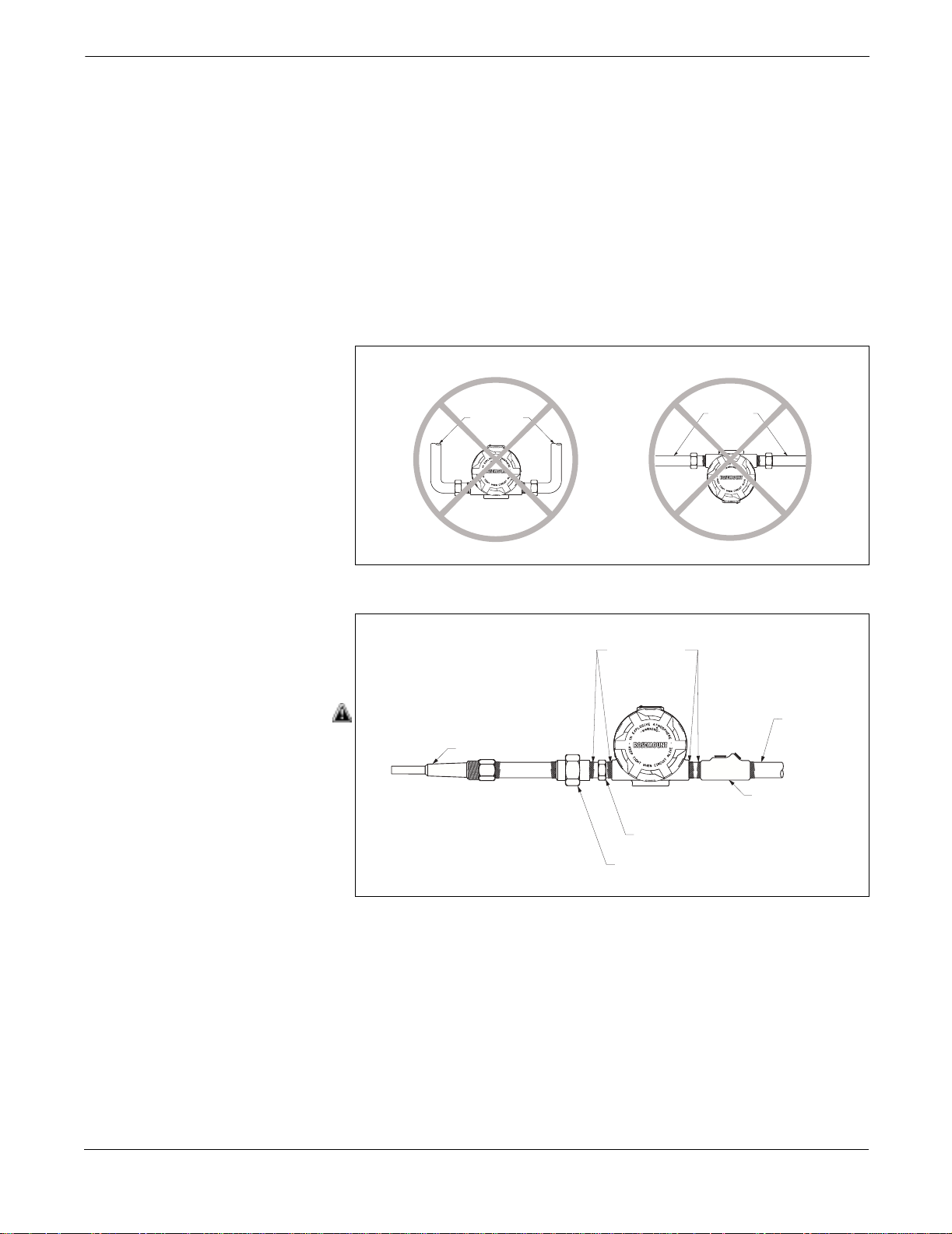
Proper installation of the transmitter ensures maximum operation and
service life. It can also have a significant impact on preventing moisture
from accumulating in the housing. Refer to Figure 2-9 before mounting
the transmitter.
If possible, mount the transmitter at a high point in the conduit run so
moisture from the conduits will not drain into the housing. If the
transmitter is mounted at a low point, the terminal compartment could
fill with water. In some instances the installation of a poured conduit
seal, such as the one pictured in Figure 2-10, is advisable. Periodically
remove the terminal compartment cover and inspect the transmitter for
moisture and corrosion.
Figure 2-9. IncorrectConduit
Installation
Figure 2- 10. Process Mounting with
Drain Seal
Hazardous Location Installations
Sealing
Compound
Conduit for
Field Wiring
Thermowell
Poured
Conduit Seal
Sensor Hex
Union Coupling
with Extension
(Where Required)
The Model 3244MV is designed with an explosion-proof housing and
circuitry suitable for intrinsically safe and non-incendive operation.
When specified, each transmitter is marked with an approval label. To
maintain certified ratings, install in accordance with all applicable
installation codes and approval drawings (Section 8: Hazardous Area
Approval Installation Drawings). Verify that the atmosphere in which
the transmitter operates is consistent with the appropriate hazardous
location certifications. Both transmitter covers must be fully engaged to
meet explosion-proof requirements.
3144-0429A, 0429B
3144-0430B
2-12
Page 27
Installation
NOTE
Once a transmitter labeled with multiple approval types is installed, it
should not be reinstalled using any other labeled approval types. To
ensure this, the approval label should be permanently marked to
distinguish the used from the unused approval types.
INSTALLATION PROCEDURES
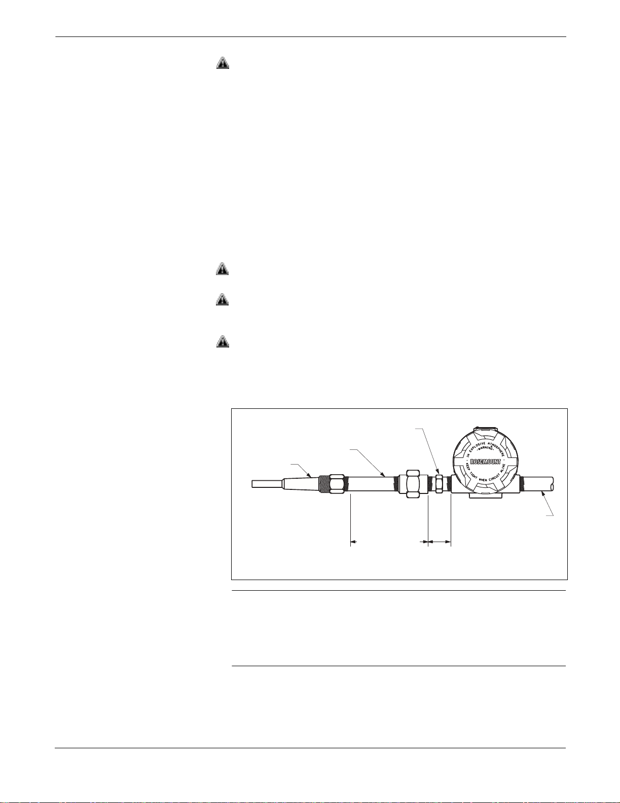
Figure 2- 11. Direct Mount and Remote
Mount Examples
Installation of the transmitter consists of mounting the transmitter, the
sensor, and making the electrical connections. You can mount the
transmitter directly to the sensor assembly or you can mount it
remotely (Figure 2-11). For a remote mount, use conduit or suitable
shielded cable with cable glands. The remainder of this section provides
the installation procedures for typical configuration in North America
and Europe.
Connection
Direct
Mount
Sensor
Assembly
Process Vessel
Sensor
Assembly
Head
Remote
Mount
Conduit or
Shielded Cable
3144-3144_04B
2-13
Page 28
Rosemount Model 3244MV MultiVariable Temperature Transmitter with Foundation Fieldbus
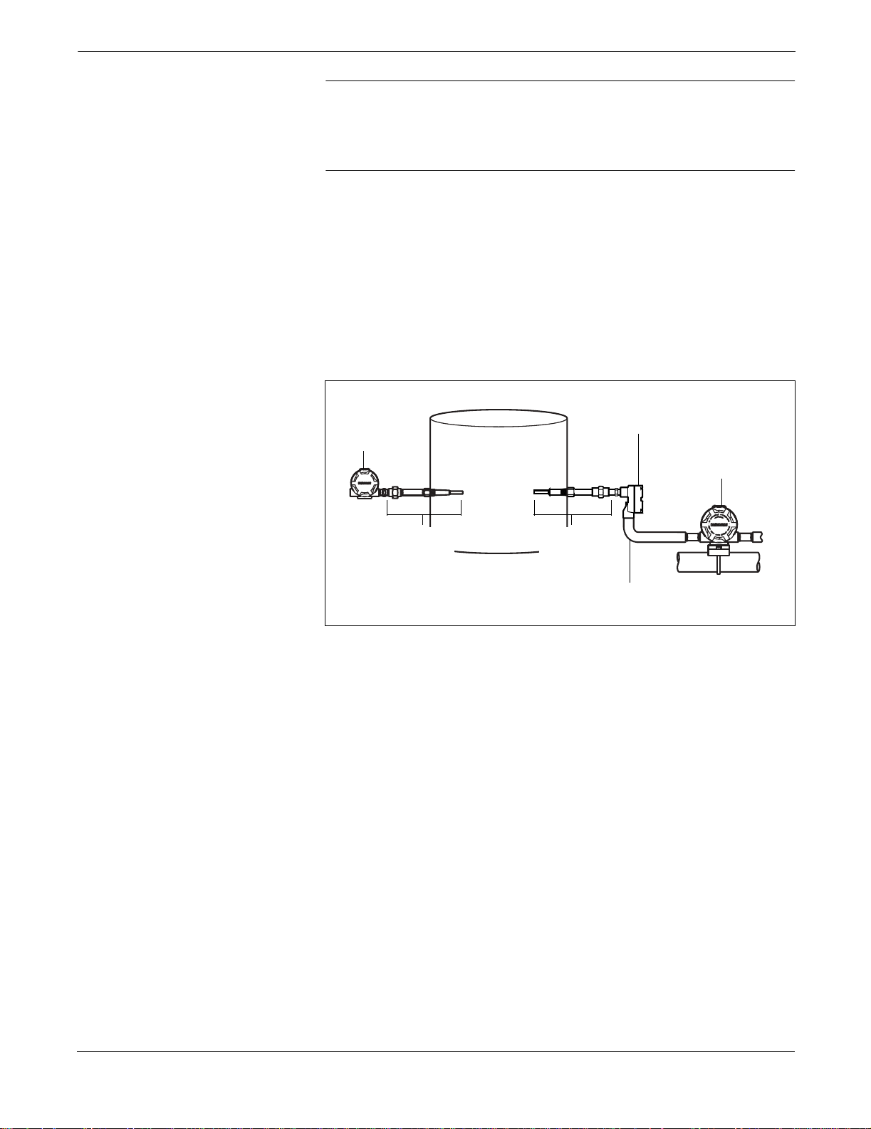
Typical North American Configuration
1. Mount the thermowell to the pipe or process container wall. Be
sure to install and tighten thermowells and sensors. Perform a
leak check before applying pressure.
2. Attach any necessary unions (or couplings) and extension
fittings. Seal the fitting threads with silicone or tape (if required).
3. Screw the sensor into the thermowell.
4. Verify all sealing requirements for severe environments or to
satisfy code requirements.
5. Attach the transmitter to the thermowell assembly. Seal all
threads with silicone or tape (if required).
6. Pull sensor leads through the extensions and unions (or
couplings) into the terminal side of the transmitter housing.
7. Install conduit for field wiring to the remaining conduit entry of
the transmitter.
8. Pull the field wiring leads into the terminal side of the
transmitter housing. Avoid contact with leads and terminals.
9. Attach the sensor leads to the transmitter sensor terminals.
Attach the power leads to the transmitter power terminals. Avoid
contact with the leads and the terminals.
10. Attach and tighten both transmitter covers. Both transmitter
covers must be fully engaged to meet explosion-proof
requirements
Figure 2-12. Typical North American
Process M ounting Configuration
Sensor Hex
Union or Coupling
and Extension
Thermowell
Conduit for
3.2
Extension
Fitting
Length (E)
Note: Dimensionsare in inches (millimeters)
(81)
Field Wiring
(dc power)
NOTE
To prevent process fluid from entering the electrical conduit and
continuing to the control room, the National Electrical Code requires
that a barrier or seal be used in addition to the primary (sensor) seal.
Professional safety assistance is recommended for installations in
potentially hazardous processes.
Fieldbus-3244MV-0433B
2-14
Page 29
Installation
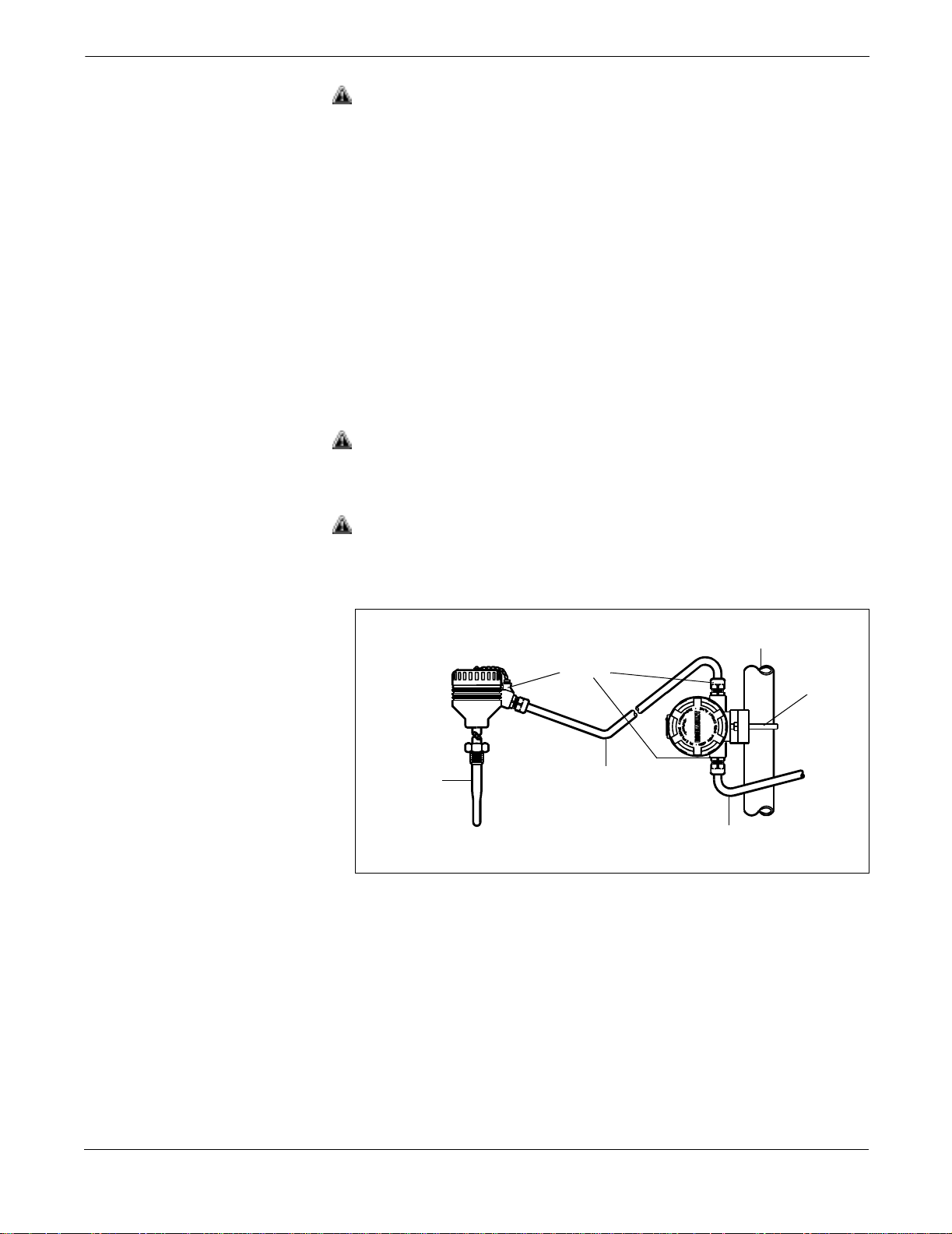
Typical European Configuration
1. Mount the thermowell to the pipe or the process container wall.
Install and tighten thermowells and sensors. Perform a leak
check before applying
process pressure.
2. Attach the connection head to the thermowell.
3. Insert the sensor into the thermowell and attach it to the
connection head.
4. Mount the transmitter to a 2-inch pipe or a suitable panel using
one of the optional mounting brackets (see Figure 2-7 on page
-10). The B4 mounting bracket is shown in Figure 2-13.
5. Attach cable glands to the shielded cable running from the
connection head to the transmitter and from the transmitter to
the control room.
6. Insert the shielded cable leads into the connection head and the
transmitter through the cable entries. Connect and tighten the
cable glands.
7. Connect the shielded cable leads to the sensor wiring leads inside
of the connection head, and the sensor wiring terminals inside
of the transmitter housing. Avoid contact with the leads and
the terminals.
8. Connect the shielded cable leads to the transmitter power
terminals. Avoid contact with the leads and the terminals.
Figure2-13. Typical European Process
Mounting Configuration
Sensor/
Thermowell
Cable
Glands
Shielded
Cable
fromSensor
2-Inch Pipe
Shielded Cable
from Transmitter
to Control Room
B4
Mounting
Bracket
644-0000B05b
2-15
Page 30

Rosemount Model 3244MV MultiVariable Temperature Transmitter with Foundation Fieldbus
2-16
Page 31

Section
3 Operation
OVERVIEW
Figure 3- 1. Block Diagram for
the Model 3244MV with
OUNDATION Fieldbus
F
User-Selectable Input
!
!
!
!
This section covers basic operation and configuration procedures for the
Model 3244MV MultiVariable Temperature Transmitter with
F
OUNDATION fieldbus (Device Revision 3). The device revision number
can be found in the Resource Block DEV_REV parameter. Figure 3-1
illustrates how the temperature signal is channeled through
the transmitter.
F
OUNDATION Fieldbus
Compliant
Communications
Stack with
Backup LAS
Function Blocks
!
!
!
!
!
Resource Block
!
!
Analog-to-Digital
Signal Conversion
Transducer Block
!
!
!
!
!
!
Input-to-Output
Galvanic Isolation
Sensor 1
Sensor 2*
* Sensor 2 is optional. Can be used as a secondary sensing element in a dual-element sensor.
Cold Junction
Compensation
Each FOUNDATION fieldbus host or configuration tool has a different
way of displaying and performing configurations. Some will use Device
Descriptions (DD) and DD Methods to make configurations and to
display data consistently across platforms. There is no requirement
that a host or configuration tool support these features.
NOTE
The information in this section will describe how to manually configure
the Model 3244MV. For information regarding the implementation of
these common functions using the DeltaV System with AMSinside from
Fisher-Rosemount, refer Appendix G: Operation with
Fisher-Rosemount® DeltaV™.
3144-3144_01B
3-1
Page 32

Rosemount Model 3244MV MultiVariable Temperature Transmitter with Foundation Fieldbus
For more information about the FOUNDATION fieldbus technology and
the function blocks used in the Model 3244MV, refer to Section 4:
Transducer Block, Section 5: Resource Block, and Appendix A:
Foundation™ Fieldbus Technology through Appendix H: European
ATEX Directive Information.
DEVICE TAG AND
NODE ADDRESS
Unless a device tag name is specifically ordered, the transmitter is
shipped with a default device tag. All devices are shipped with a
temporary address (between 25P and 25I). This allows the host to
automatically commission the transmitter. If the tag or address
changes, use the configuration tool to perform the following functions:
1. Change the address to a temporary address (between 248
and 251).
2. Change the tag to a new value.
3. Change the address to a new address.
When the device is at a temporary address, only the tag and address
can be changed or written to. The resource, transducer, and function
blocks are all disabled.
TEMPERATURE SP ECIFIC BLOCK CONFIGURATION
Only the Transducer Block, Analog Input function blocks, and Input
Selector function block have configurations for temperature-specific
parameters. Other function blocks that are used for control and/or
monitoring applications are configured by links made from the Analog
Input (and/or Input Selector) block. See Appendix B: Analog Input
Function Blockfor specific application examples.
Transducer Block The sensor type and connections for the Transducer Block have been
preconfigured at the factory according to customer selected
specifications (see below table).
3-2
Sensor Type Connections Configuration
Pt 100, α
Pt 100, α
щьэшээюъыьчця
щьэшээюъыьчця
4-wire Standard
two 3-wire U1, U4, U5, U6, U7, U8 or U9
NOTE:
This table does not reflect modifications you may have using the
Configuration Data Sheet.
It may be necessary to change these settings in the field depending on
what type of sensor is being connected. This is done using any
F
OUNDATION fieldbus host or configuration tool that supports DD
methods. For a description of the sensor connection method, “Changing
the Sensor Configuration” on page 4-8.
NOTE
If only one single-element sensor is used but both sensor 1 and sensor 2
are configured, PRIMARY_VALUE_2 will have a status of bad and a
substatus of sensor failure and DIFFERENTIAL_TEMPERATURE will
have a status of bad and substatus of not specific.
Page 33

Operation
See Section 4: Transducer Block for more details on configuring and
troubleshooting the Transducer Block.
Back-up LAS The model 3244MV comes as a Link Master (LM) class device. With this
feature, the Model 3244MV can become a fully functioning Link Active
Scheduler (LAS) in the event that the primary LAS (typically the host
system) fails. Appendix A: Foundation™ Fieldbus Technology provides
a detailed explanation of the communications and LAS features and
parameters.
Analog Input
Function Block
The Analog Input (AI) function block provides the link that
communicates the
to the F
OUNDATION fieldbus. The interface between each AI block and
temperature measurement in the transducer block
the transducer block is through the three parameters that are listed
below. These parameters have already been preconfigured at the factory
according to your specified configuration. They can be changed in the
field using any F
OUNDATION fieldbus host or configuration tool that
supports DD methods.When necessary, use the order indicated below to
change these parameters:
1. CHANNEL: Defines which transducer block measurement is
used by the AI block.
For example, CHANNEL parameters for option code U1: Hot
Backup (Control and Safety Applications) would be as follows:
ьяъшцхьффюэыщ ыъыучът
ьяшцхьффюэыщ ыыучт
ьяшцхьффюэыщ ыыу∆чт
2. XD_SCALE.UNITS_INDX: Defines the engineering units
associated with the channel input value. Default configuration is
°C for all AI blocks
3. L_TYPE: Determines whether the field value is used directly
(Direct), converted linearly (Indirect), or is converted with the
square root (Indirect Square Root). Since the temperature
measurement from the transducer block is in the correct units,
L_TYPE is configured as Direct. L_TYPE is usually only changed
to Indirect or Indirect Square Root if the measurement type
changes. For example, changing mV into temperature.
Input Selector
Function Block
See Appendix B: Analog Input Function Block for more details on
configuring and troubleshooting the AI blocks.
The Input Selector (ISEL) function block is used to output a specific
selection strategy using inputs from AI function blocks. The ISEL block
has already been preconfigured at the factory according to your
specified transmitter configuration (see below table). The configuration
can easily be changed in the field using any F
OUNDATION fieldbus host
or configuration tool that supports DD methods.
Configuration Select _Type Parameter IN_1 Parameter IN_2 Parameter
U1 Hot Backup
U6 AVG = Average AI1 OUT AI2 OUT
U7 First Good AI1 OUT AI2 OUT
U8 MIN = Minimum AI1 OUT AI2 OUT
U9 MAX = Maximum AI1 OUT AI2 OUT
®
AI1 OUT AI2 OUT
3-3
Page 34

Rosemount Model 3244MV MultiVariable Temperature Transmitter with Foundation Fieldbus
NOTE
The links from the AI blocks to the ISEL block must be configured for
the transmitter to execute properly in your application
(see “Configuring Links and Scheduling Block Execution” on page 3-4).
See Appendix C: Input Selector Function Blockfor more details on
configuring and troubleshooting the ISEL block.
NOTE
The factory default configuration can be replaced by downloading the
default configuration from any FOUNDATION fieldbus host.
CONFIGURING LINKS
AND SCHEDULING
BLOCK EXECUTION
For your application to work properly, you must configure the links
between the function blocks and schedule the order of
The Graphical User Interface (GUI) provided by your F
fieldbus host and/or configuration tool will allow you to easily perform
these configurations.
Your Model 3244MV was preconfigured at the factory according to your
specifications. The measurement and control strategies shown below
represent some of the common types of configurations available in the
Model 3244MV. Although the appearance of your GUI screens will vary
from host to host, the configuration logic is the same for all hosts.
NOTE
If configured improperly, your F
configuration tool could overwrite the default transmitter
configuration. Please ensure that your host system or configuration tool
is properly configured prior to downloading the transmitter
configuration.
OUNDATION fieldbus host or
their execution.
OUNDATION
3-4
Page 35

Operation
Hot Backup Configuration (option code U1)
Figure 3- 2. Hot Backup Link
Configuration
Configure the links and block execution order as shown in Figure 3-2
and 3-3. This configuration optimizes your transmitter for use in a
control and safety application.
The use of a dual-element sensor is recommended with this
configuration. The ISEL Block SELECT_TYPE parameter = Hot
Backup. The AI3 Block alarm parameters are set to detect sensor drift.
For more details on how to configure these parameters, see “Sensor
Drift Alert Configuration” on page -13.
Transducer
Block (TB )
T1
TT
T2
DT
Analog Input
Block 1 (AI1)
OUT
Analog Input
Block 2 (AI2)
OUT
Analog Input
Block 3 (AI3)
OUT
Input Selector
Block (ISEL)
IN 1
OUT
IN 2
T1 = Primary sensing element in
a dual-element sensor
TT = Terminal Temperatur e
T2 = Secondary sensing element
in a dua l-element s ensor
DT = Differential Temperature
FIELDBUS_3244MV_ 0001A
Figure 3- 3. Hot Backup Block
Execution Order
Macrocycle
AI 1
AI 2
AI 3
ISEL
FIELDBUS_3244MV _05B
3-5
Page 36

Rosemount Model 3244MV MultiVariable Temperature Transmitter with Foundation Fieldbus
Two Independent
Sensors Configuration
(option code U4)
Figure 3-4. Two Independent Sensors
Link Configuration
Configure the links and block execution order as shown in Figure 3-4
and Figure 3-5. This configuration optimizes your transmitter for use in
a monitoring application.
The use of two single-element sensors is recommended with this
configuration.
Transducer
Block (TB)
T1
TT
T2
DT
Analog Input
Block 1 (A I1)
OUT
Analog Input
Block 2 (A I2)
OUT
Analog Input
Block 3 (A I3)
T1 = Sensor 1 Temperature
TT = Terminal Temperature
T2 = Sensor 2 Temperature
DT = Differential Temperature
Figure 3-5. Two Independent Sensors
Block Execution Order
OUT
FIELDBUS_3244MV _0002B
Macrocycle
AI 1
AI 2
AI 3
FIELDBUS_3244MV _05C
3-6
Page 37

Operation
Differential Temperature Configuration (option code U5)
Figure 3-6. Diff erential Temper ature
Link Configuratio n
Configure the links and block execution order as shown in Figure 3-6
and Figure 3-7. This configuration is used to measure the differential
temperature between two processes.
Transducer
Block (TB)
T1
TT
T2
DT
Analog Input
Block 2 (AI2)
OUT
Analog Input
Block 3 (AI3)
OUT
Analog Input
Block 1 (AI1)
OUT
T1 = Sensor 1 Temperature
TT = TerminalTemperature
T2 = Sensor 2 Temperature
DT = Differential Temperature
LDBUS_3244MV_0002B
Figure 3-7. Diff erential Temper ature
Block Execution Order
Average Temperature
Configur ation
(Option Code U6)
First Good Temperature
Configuration
(Option Code U7)
Minimum Temperature
Configuration
(Option Code U8)
Macrocycle
AI 1
AI 2
AI 3
FIELDBUS_3244MV_05C
This configuration is used to measure the average temperature between
two processes.
This configuration is used to output the first sensor measurement with
a status of “GOOD.”
This configuration is used to output the minimum temperature between
two sensors.
3-7
Page 38

Rosemount Model 3244MV MultiVariable Temperature Transmitter with Foundation Fieldbus
Maximum Temperature
Configuration
(Option Code U9)
Figure 3-8. Average, First Good,
Minimum, and Maximum Temperature
Link Configuration
This configuration is used to output the maximum temperature
between two sensors.
Configure the links and block execution order as shown in Figure 3-8
and Figure 3-9 for the Average, First Good, Minimum and Maximum
Temperature Configurations.
Refer to “Input Selector Function Block” on page -3 to determine the
corresponding SELECT_TYPE parameter settings. The AI3 Block
alarm parameters are set to detect sensor drift. For more details on how
to configure these parameters, see “Sensor Drift Alert Configuration”
on page -13.
Transducer
Block (TB)
T1
TT
T2
DT
Analog Input
Block 1 (AI1)
OUT
Analog Input
Block 2 (AI2)
OUT
Input Selector
Block (ISEL)
IN 1
OUT
IN 2
Figure 3-9. Average, First Good,
Minimum, and Maximum Temperature
Block Execution Order
Analog Input
Block 3 (AI3)
OUT
AI 1
T1 = Primary sensing element in a
dual-element sensor
TT = Terminal Temperature
T2 = Secondary sensing element in a
dual-element sensor
DT = Differential Temperature
FIELDBUS_3244MV_0001A
Macrocycle
AI 2
AI 3
ISEL
FIELDBUS_3244MV_05B
3-8
Page 39

Operation
Single Sensor Configuration (standard)
Figure 3-10. Single Sensor
Link Configuration
Configure the links and block execution order as shown in Figure 3-10
and Figure 3-11.
TB Block
T1
TT
T2
DT
AI1 Block
OUT
T1 = Sensor 1 Temperature
TT = Termi nal Temperature
T2 = Sensor 2 Temperature
DT = Differential Temperature
AI2 Block
OUT
FIELDBUS_3244MV _0002A
Figure 3-11. Single Sensor Block
Execution Order
Macrocycle
AI1
AI2
Critical Control Application Configure the links and block execution order as shown in Figure 3-12
and Figure 3-13. This configuration optimizes your transmitter for use
in a critical control application. This type of application requires a
redundant sensor that allows the process to continue if one of the
temperature sensing elements fail. The Model 3244MV MultiVariable
Temperature Transmitter Hot Backup feature or First Good
configuration is ideal for this application.
The use of a dual-element sensor is recommended with this
configuration. The ISEL Block SELECT_TYPE parameter = Hot
Backup or First Good. The AI3 Block alarm parameters are set to detect
sensor drift. For more details on how to configure these parameters, see
“Sensor Drift Alert Configuration” on page -13.
FIELDBUS_3244MV _05D
3-9
Page 40

Rosemount Model 3244MV MultiVariable Temperature Transmitter with Foundation Fieldbus
Figure 3- 12. Critical Control
Link Configuration
TB Block
AI1 Block
Figure 3- 13. Critical Control Block
Execution Order
T1
TT
T2
DT
T1 = Primary sensing elementin a dual-element sensor
TT = TerminalTemperature
T2 = Secondary sensing element in a dual-element sensor
DT = Differential temperature used to detectsensor drift.
OUT
IN 1
IN 2
AI2 Block
OUT
AI3 Block
OUT
Macrocycle
PID BlockISEL Block
IN
OUTOUT
BKCAL IN
AO Block
CAS IN
BKCAL OUT
FIELDBUS_3244MV_0004A
AI 1
AI 2
AI 3
ISEL
PID
AO
Control
Valve
FIELDBUS_3244MV_05A
3-10
Page 41

Figure 3-14. Cascade Control
Link Configuration
Operation
Cascade Control Application
Configure the links and block execution order as shown in Figure 3-14
and Figure 3-15. This configuration optimizes your transmitter for use
in a cascade temperature control application. The use of two
single-element sensors is recommended with this configuration.
TB Block
AI1 Block
PID1 Block
PID2 Block
Figure 3-15. Cascade Control Block
Execution Order
T1
TT
T2
DT
T1 = Sensor 1 Temperature
TT = Terminal Temperature
T2 = Sensor 2 Temperature
DT = Differential Temperature
OUT
AI3 Block
OUT
AI2 Block
OUT
Macrocycle
IN
BKCAL
OU
IN
CAS IN
OUT
BKCAL IN
BKCAL OUT
AO Block
CAS IN
BKCAL OUT
FIELDBUS_3244MV _0005A
AI 1
AI 2
AI 3
PID 1
PID 2
AO
Control
Valve
3-11
FIELDBUS_3244MV_05A
Page 42

Rosemount Model 3244MV MultiVariable Temperature Transmitter with Foundation Fieldbus
Fluid D ensity Application
The Model 3244MV available with an Arithmetic Function Block, which
is useful in many types of temperature applications, such as calculating
fluid density. Since many liquids are virtually incompressible fluids,
temperature is often used as the main variable for determining fluid
density. The temperature of the fluid can be converted into density by
using the fourth order polynomial capability of the Arithmetic block.
Figure 3-16 shows the applicable links for the Arithmetic Function
Block. In this example, the ARITH-TYPE parameter = Fourth
order polynomial.
Figure 3-16. ArithmeticFunction Block
Link Configuration
AI Output
or ISEL
Output
IN
IN_LO
IN1
OUT
Output to a control
strategy and / or
monitoring application
Figure 3-17. Signal Characteri zer
Function Block Link Configuration
IN2
IN3
Arithmetic
Block
Infrared Sensor Input Application
The transmitter is available with a Signal Characterizer Function
Block which is useful in many types of temperature applications, such
as converting mV to temperature for an IR sensor. Since this conversion
is typically a non-linear function, the Signal Characterizer block is ideal
with its X–Y coordinate input capability.
Figure 3-17 shows the application links for the Signal Characterizer
Function Block.
Characterizer
Function Block
AI Output
or ISEL
Output
IN1 OUT1
OUT2IN2
Output to a control
strategy and / or
monitoring application
FIELDBUS_3244MV_3244-06A
3-12
IELDBUS_3244MV_3244-07A
Page 43

Operation
Sensor Drift Alert Configuration
The Sensor Drift Alert configuration feature aids in the prediction of
sensor failures. This feature should be used when measuring the same
process temperature, such as with a dual-element sensor.
Use the following steps to set up Sensor Drift Alert:
1. Assign an AI block to the differential temperature measurement
in the Transducer Block. When the sensors are working properly,
the differential temperature should be near zero.
2. Set the maximum allowable temperature difference (drift)
between sensor 1 and sensor 2 by setting the alarm limit
parameters HI_LIM and LO_LIM in the AI block.
NOTE:
If Custom Configuration Options U1, U6, U7, U8, or U9 are ordered,
the AI3 alarm parameters are preconfigured as follows:
HI_LIM = 5.4 °F (3.0 °C)
LO_LIM = –5.4 °F (–3.0 °C)
3. An alert is generated when the transmitter detects a
temperature difference that exceeds the alarm limits.
Figure 3-18. Sensor Drift Alert Diagram
4. Additional bands of drift can be configured by using HI_HI_LIM
and LO_LO_LIM. This is done to identify warning and failure
points in a temperature application.
Warning / Failure
HI_HI_LIM
Sensor Drift Alert
HI_LIM
Differential
Temperature
LO_LIM
LO_LO_LIM
0°C
Time
FIELDBUS_3244MV_08A
3-13
Page 44

Rosemount Model 3244MV MultiVariable Temperature Transmitter with Foundation Fieldbus
3-14
Page 45

Section
4 Transducer Block
OVERVIEW This section contains information about the Model 3244MV
MultiVariable Temperature Transmitter Transducer Block (TB) and its
parameters, errors, and diagnostics. Modes, alarm detection, status
handling, application information, and troubleshooting are also
discussed.
Figure 4-1. Transducer
Block Diagram
AID Signal
Conversion
Dampin g
CJC
Lineari zation
Temperature
Compensation
Units / Ranging
Channel
Channel
Channel
Channel
T1
1
2
TT
3
T2
4
DT
Diagnostics
Definition The Transducer Block contains temperature measurement data,
including Sensor 1, Sensor 2, differential, and terminal temperatures.
Channels 1–4 are assigned to these temperature measurements (see
Figure 4-1 above). The Transducer Block also includes information
about sensor type, engineering units, linearization, reranging,
damping, temperature compensation, and diagnostics.
Channel Definitions The Model 3244MV supports multiple sensor inputs. Each input has a
channel assigned to it that allows the AI block to link to it. The
channels for the Model 3244MV are as follows:
• Channel T1 (Sensor 1 temperature)
• Channel TT (Terminal temperature)
• Channel T2
(Sensor 2 temperature)
• Channel DT = T1 – T2 (Differential temperature)
NOTE
Whenever the transducer block is configured with 2 inputs the
Differential Temperature (DT) is calculated.
(1)
(2)
FIELDBUS_3244MV_FBUS_42A
(1) T1 is the primary sensing element in a dual-element sensor.
(2) T2 is the secondary sensing element in a dual-element sensor.
4-1
Page 46

Rosemount Model 3244MV MultiVariable Temperature Transmitter with Foundation Fieldbus
Parameters and Descriptions
TABLE 4-1. Transducer Block
Parameters
Parameter
A2D_BRD_HRDWR_REV 65 A/D board hardware revision.
A2D_BRD_SN 64 A/Dboardserial number.
A2D_CONVERSION_INFO 69 Indicate whether your input power has 60Hz or 50Hz line cycle.
A2D_SOFTWARE_REVISION 67 Software revision.
A2D_SOFTWARE_REV_NU
M
ALERT_KEY 04 The identification number of the plant unit. This information may be used in the host for sorting
BLOCK_ALM 08 Theblock alarm is used forall configuration, hardware,connectionfailureor systemproblems in
BLOCK_ERR 06 This parameterreflects the error status associated with the hardwareor software components
CALIBRATOR_MODE 71 Calibrator mode. Used to determine the mode of the calibration logic.
CAL_MIN_SPAN (_2)
CAL_POINT_HI (_2)
CAL_PT_HI_LIMIT (_2)
CAL_POINT_LO (_2)
CAL_PT_LO_LIMIT (_2)
CAL_UNIT (_2)
(1)
(1)
(1)
(1)
(1)
(1)
CJC_CALIBrATION_VALUE 68 The CJ C calibration value.
CJC_MODE 72 CJC mode.
COLLECTION_DIRECTORY 12 A directory that specifies the number starting indices and DD Item ID's of the data collections in
DAMPING (_2)
(1)
DIFFERENTIAL_DAMPING 75 Differential damping.
DIFFERENTIAL_LIMITS 77 Differential limits.
DIFFERENTIAL_RANGE 76 Differential range.
(1) “Special sensor matching coefficientsA, B, C, and R0are used by the Model 3244MV Transducer Block. Callendar-Van Dusen sensor matching
constants alpha (
a
), delta (d), beta (b) and R0can be entered using the DD method.
Index
Number
Description
0 = “60 Hz”, “Choose this if your input powerhas 60Hz line cycle”,
1 = “50 Hz”, “Choose this if your input powerhas 50Hz line cycle”
66 A/D software rev number.
alarms, etc.
the block.The cause of t he alert is enteredin the subcode field. The first alert to become active
will set the Active status in the Status parameter. As soon as the Unreported status is cleared by
the alert reporting task, another block alert may be reported without clearing the Active status, if
the subcode has changed.
associated with a block. It is a bit string, so that multiple errorsmay be shown.
0 = “Disabled,”“Choose this if you are doing an inputtrim to minimizeinteractionbetween the
device and the calibrationhardware”,
1 = “Enabled”, “Choose this for normal operation and the best open sensor diagnostics”
18, 40 The minimum span that must be used between the calibration high and low points.
16, 38 The value of the Primary Value measurementused for the high calibration point.
21, 43 High calibrationpoint limit. A valuegreaterthan this shouldnot be used for the CAL_POINT_HI.
17, 39 The value of the Primary Value measurementused for the low calibration point.
22, 44 Low calibration point limit. A value less than this should not be used for the CAL_POINT_LO.
19, 41 The units used for the calibrationinputs.Valid calibration units are the following:
1000 = K
1001 = °C
1002 = °F
1003 = °R
1243 = mV
1281 = ohm
each transducer within a transducer block.
20, 42 Sampling interval used to smooth output using a 1st order linearfilter.
Continued on Next Page
4-2
Page 47

Transducer Block
DIFFERENTIAL_TEMPERATURE 74 Differential temperature (channel output #4).
MODE_BLK 05 The actual, target, permitted,and normal modes of the block.
Target: The mode to “go to”
Actual: The mode the “block is currentlyin”
Permitted: Allowed modes that target may take on
Normal:Most common mode for target
MODULE_SN 59 The A/D module serial number.
NUMBER_OF_INPUTS 78 Number of inputs.
PRIMARY_VALUE_RANGE (_2)
PRIMARY_VALUE 14 The value of the measurement, i.e. temperature sensor input#1 (channel output #1).
PRIMARY_VALUE_2 36 The value of the measurement,i.e.temperaturesensor input #2 (channeloutput #3).
PRIMARY_VALUE_TYPE (_2)
RTD_OFFSET_COMPENSATION 70 RTD offset compensation.
SECONDARY_VALUE 57 The secondary value,i.e. terminaltemperature (channel output #2).
SECONDA RY_VALUE_DAMPING 62 Secondary value damping.
SECONDARY_VALUE_LIMITS 61 Secondary value limits.
SECONDARY_VALUE_RANGE 60 Secondary value range.
SECONDARY_VALUE_UNIT 58 Engineering units to be used with SECONDARY_VALUE.
SENSOR_CAL_DATE (_2)
SENSOR_CAL_LOC (_2)
SENSOR_CAL_METHOD (_2)
SENSOR_CAL_WHO (_2)
SENSOR_CONNECTION (_2)
SENSOR_RANGE (_ 2)
SENSOR_SN (_2)
(1) Special sensor matching coefficients A, B, C, and R0are used by the Model 3244MV Transducer Block. Callendar-Van Dusen sensor
matching constants alpha (
(1)
15, 37 The High and Low rangelimit values, the engineering units code, and the number of
digits to the right of the decimal point to be used to display the Primary Value.
Valid engineering units are the following:
1000 = K
1001 = °C
1002 = °F
1003 = °R
1243 = mV
1281 = ohm
(1)
13, 35 Type of measurement of the primary value.
104 = processtemperature
0 = “Disabled”, “Choose this if you want offset compensation disabled”,
1 = “Enabled”, “Choose this fornormal operation and the best sensormeasurement
accuracy possible”
(1)
(1)
28, 50 The last date on which the calibration was performed.
27, 49 The last location of the sensor calibration.
(1)
26, 48 The last method used to calibrate the device, e.g. factory calibration or user specific.
103 = factory trim standard
104 = user trim standard
(1)
29, 51 The name of the person responsible for the last sensor calibration.
(1)
30, 52 The number of wires for the temperature probe.Valid values are:
2=2wiresensor
3=3wiresensor
4=4wiresensor
(1)
24, 46 The High and Low rangelimit values, the engineering units code, and the number of
digits to the right of the decimal point for the sensor. These represent the nominal high
and low range values for the sensor type.
(1)
25, 47 Serialnumberof the sensor.
Continued on Next Page
a
), delta (d), beta (b)andR0can be entered using the DD method.
4-3
Page 48

Rosemount Model 3244MV MultiVariable Temperature Transmitter with Foundation Fieldbus
SENSOR_TYPE (–2)
(1)
23, 45 Type of sensoron input #1. Validones are ohms, mV, PT-(many), TC-(many).
Valid sensor types are the following:
103 = mV
104 = Ohms
128 = PT100_A_385 (IEC 751)
129 = PT100_A_392 (JIS 1604)
130 = PT200_A_385 (IEC 751)
131 = PT500_A_385 (IEC 751)
132 = NI120, Edison #7
133 = Cu10, Edison #15
134 = T/C TypeB (IEC 584-1,NIST 175)
136 = T/C TypeE (IEC 584-1,NIST 175)
137 = T/C Type J (IEC 584-1, NIST 175)
138 = T/C TypeK (IEC 584-1,NIST 175)
139 = T/C Type N (IEC 584-1, NIST 175)
140 = T/C Type R (IEC 584-1, NIST 175)
141 = T/C TypeS (IEC 584-1,NIST 175)
142 = T/C TypeT (IEC 584-1,NIST 175)
145 = PT1000_A_385 (IEC 751)
146 = User-defined—Calvandu
147 = User-defined—RTD/Ohms
148 = User-defined—T/C, mV
65534 = Not used
SPECIAL_SENSOR_A (_2)
SPECIAL_SENSOR_B (_2)
SPECIAL_SENSOR_C (_2)
SPECIAL_SENSOR_R0 (_2)
(1)
(1)
(1)
32, 54 Specialsensormatching coefficients—A Value
33, 55 Specialsensormatching coefficients—B Value
34, 56 Specialsensormatching coefficients—C Value
(1)
31, 53 Specialsensormatching coefficients—R0Value
(2)
(2)
(2)
(2)
STRATEGY 03 The strategy field can be used to identify grouping of blocks. This data is not checked or
processed by the block.
ST_REV 01 The revision level of the static data associated with the function block. The revision value
will be incremented each time a static parameter value in the block is changed.
TAG_DESC 02 The user description of the intended application of the block.
TB_COMMAND_ST ATUS 63 Transducer board command status.
0 = No Command Active
1 = Command Executing
2 = Command Done
3 = Command Done: Errors
TB_ELECTRONICS_STATUS 73 TB electronics status. See Diagnostics below.
TRANSDUCER_DIRECTORY 09 Directory that specifies the nu mber and starting indices of the transducers in t he
transducer block.
TRANSDUCER_TYPE 10 Identifies the transducer that follows.
UPDATE_EVT 07 This alert is generatedby any changeto the static data.
XD_ERROR 11 A transducer block alarm subcode.
(1) “_2” is added to the given parameter for sensor 2 (secondary sensing elements).
(2) SpecialsensormatchingcoefficientsA, B, c andR
α
constants alpha (
), delta (δ), beta (β), and R0can be entered using the DD method.
are used by the Model 3244MV Transducer Block. Callendar-VanDusen sensor matching
0
4-4
Page 49

Transducer Block
Block/Transducer Errors The following conditions are reported in the BLOCK_ERR and
XD_ERROR parameters. Conditions in italics are inactive for the
Transducer block and are given here only for your reference.
T ABLE 4-2. BLOCK_ERR and
XD_ERR Conditions
Condition Number Condition Name and Description
0Other
1 BlockConfiguration Error
2 Link Configuration Error
3 Simulate Active
4 Local Override
5 Device Fault State Set
6 Device Needs Maintenance Soon
7 Input failure/process variable has bad status
8 Output Failure
9 Memory Failure
10 Lost Static Data
11 Lost NV Data
12 Readback Check Failed
13 Device Needs Maintenance Now
14 Power Up: The device was just powered-up.
15 Out of Service:The actual mode is out of service.
16 Unspecifiederror: An unidentified error occurred.
17 General Error: A generalerror that cannot be specified below occurred
18 Calibration Error: An error occurred during calibration of the device or a calibration
error was detected during normal operations.
19 Configuration Error: An error occurredduring configurationof the device or a
configuration error was detected during normal operations.
20 Electronics Failure: An electrical component failed.
21 Mechanical Failure: A mechanical component failed.
22 I/O Failure: An I/O failure occurred.
23 Data Integrity Error:Datastoredinthedeviceisnolongervalidduetoa
non-volatile memory checksum failure, a data verify after write failure, etc.
24 Software Error: The software has detected an error due to an improper interrupt
25 Algorithm Error: The algorithm used in the transducer blockproduced an error
service routine, an arithmetic overflow, a watchdog time-out, etc.
due to overflow, data reasonableness failure, etc.
.
4-5
Page 50

Rosemount Model 3244MV MultiVariable Temperature Transmitter with Foundation Fieldbus
Diagnostics In addition to the BLOCK_ERR and XD_ERROR parameters, more
detailed information on the measurement status can be obtained via
TB_ELECTRONICS_STATUS. Table 4-3 lists the potential errors and
the possible corrective actions for the given values. The corrective
actions are in order of increasing system level compromises.
The first step should always be to reset the transmitter and then, if the
error persists, move to the next step as indicated in Table 4-3.
TABLE 4-3. TB_
ELECTRONICS_STATUS Descriptions
and Corrective Actions
Value and
Name
0x00000040 RAM_FAILURE:“The devicehas detected a RAM failure which is usually fatal”
0x00000020 RAM_CHKSUM_FAILURE:“The devicehas detecteda RAM data integrity error which
maybe a checksum error or a data consistency error”
0x00000010 ROM_FAILURE: “The device has detected a ROM failurewhichis usually fatal”
0x00000004 CONFIGURATION_INVALID: “The device has detectedinvaliddata in the EEPROM even
though all other tests passed”
0x00000002 EEPROM_WRITE_FAILED: “The device has detectedthat a write to EPROM has failed”
0x00000001 EEPROM_CHKSUM_FAILURE: “The device has detectedan E EPROM data integrity
error which m ay be a checksum error or a data consis tency error”
0x00008000 A2D_ASIC_RX_ERR:“The transducerblock has detectedan
A/D ASIC rece ive error”
0x00004000 A2D_ASIC_TX_ERR:“Thetransducer blockhas detected an
A/D ASIC transmi ssi on error”
0x00002000 A2D_ASIC_CONVERT_ERR: “The transducerblockhas detectedan A/D ASIC had a
conversion overflow error”
0x00001000 A2D_ASIC_REF_ERR: “Thetransducer blockhas detected an A/D referenceerror”
0x00000800 A2D_ASIC_NO_IRQ: “The transducerblock has detectedthat the A/D ASIC has stopped
interrupting f or ser vice”
0x00000400 A2D_ASIC_INVALID_IRQ: “The tr ansducer block has detected that the A/D ASIC
interrupt came at the wrong time”
0x00000200 A2D_ASIC_AUTOCAL_ERR: “The transducer block has detected an A/D ASIC auto
calibrationerror”
0x00000100 A2D_ASIC_FAILURE:“The transducer has detectedan A/D ASIC general failure”
0x00080000 HOUSING_FAILURE: “The device has detected a failurein the devicehousing”
0x00100000 SENSOR_FAILURE:“The devicehas detecteda failure in one or both sensorsconnected
to the device”
0x00010000 A2D_SOFTWARE_C OMPAT_ERR: “The device has detected an incompatible version of
software in the A/D board.
0x40000000 A2D_BRD_COMM_FAILED: “The device has detected that the A/D board is not
communicatingproperly”
0x10000000 A2D_BRD_DATABASE_FAILED: “Th e d evice detected that the A/D board an d output
board databases were inconsistent”
Name and Description Corrective Actions
1.Restart the Processor.
2.Send to ServiceCenter.
1.Restart the Processor.
1.Restart the Processor.
2.Send to ServiceCenter.
1.Restart the Processor.
2.Restart with Defaults.
1.Restart the Processor.
2.Send to ServiceCenter
1.Restart the Processor.
1.Restart the Processor.
1.Restart the Processor.
1.Restart the Processor.
1.Restart the Processor.
1.Restart the Processor.
1.Restart the Processor.
1.Restart the Processor.
1.Restart the Processor.
1.Restart the Processor.
2.Replace the Housing.
1.Restart the Processor.
2.Replace the Sensor.
1.Restart the Processor.
2.Send to ServiceCenter.
1.Restart the Processor.
2.Send to ServiceCenter.
1.Restart the Processor.
2.Send to ServiceCenter.
4-6
Page 51

Transducer Block
Value and
Name
0x20000000 A2D_BRD_UPDA TE_FAILED: “The device has detected that the A/D board is generating
interrupts therefore not updating the sensor value”
0x08000000 A2D_BRD_EXCESS_EMF: “The device has detected that the excess EMF correction in
OffsetCompensationmode on the
A/D board”
0x04000000 A2D_BRD_COLD_START:“The devicehas detected that the
A/D board has gone through a cold start or equivalent.
0x02000000 A2D_BRD_CONFIG_CHANGED:“ The devicehas detected that the A/D board’s
configuration changed”
0x01000000 A2D_BRD_GENERAL_FAILURE: “The devicehas detectedthat the A/D boardhas failed”
Name and Description Corrective Actions
1.Restart the Processor.
2.Send to ServiceCenter.
1.Restart the Processor.
2.Check the Shielding.
1.No Action Necessary.
1.No Action Necessary.
1.Restart the Processor.
2.Send to ServiceCenter
Modes The transducer block supports two modes of operation as defined by the
MODE_BLK Parameter:
Automatic (Auto)—The channel outputs reflect the analog input
measurement.
Out of Service (O/S)—The block is not processed. Channel outputs
are not updated and the status is set to Bad: Out of Service for each
channel. The BLOCK_ERR parameter shows Out of Service. In this
mode, you can make changes to all configurable parameters. The target
mode of a block may be restricted to one or more of the supported
modes.
Alarm Detection Alarms are not generated by the transducer block. By correctly
handling the status of the channel values, the down stream block (AI)
will generate the necessary alarms for the measurement. The error that
generated this alarm can be determined by looking at BLOCK_ERR
and XD_ERROR.
Status Handling Normally, the status of the output channels reflects the status of the
measurement value, the operating condition of the measurement
electronics card, and any active alarm condition.
In Auto mode, OUT reflects the value and status quality of the output
channels.
Transmitter-
Sensor Matching
Callendar-Van Dusen constants from a calibrated RTD schedule can be
loaded into the Model 3244MV. A special curve is generated in the
device that matches the specific sensor to the measured input of the
RTD. This sensor matching enhances the accuracy of temperature
sensor measurement. The Callendar-Van Dusen constants are input
using the Sensor Type DD method. Selecting the User Defined sensor
type will allow you to enter the constants. These can either be entered
in the form of R
, Alpha, Beta, Delta, or the form of R0, A, B, C. See the
0
section on page 8 for more details on selecting the sensor type.
4-7
Page 52

Rosemount Model 3244MV MultiVariable Temperature Transmitter with Foundation Fieldbus
Methods Changing the Sensor Configuration
The following steps illustrate how change the sensor configuration
using the sensor connection method:
1. Set TB.MODE_BLK.TARGET = OOS.
2. Set SENSOR_CONNECTION to appropriate value (2,3,4).
3. Set SENSOR_TYPE to appropriate value (TC-x, PT-xxx, mV,
Ohms, Callandar-Van Dusen).
4. If a you are entering Callandar-Van Dusen sensor-matching
constants, set alpha (a), delta (d), beta (b), and R
5. Set TB.MODE_BLK.TARGET = AUTO.
6. Put appropriate AI block in OOS by setting
AIn.MODE_BLK.TARGET = OOS.
7. Verify AI.CHANNEL is set to correct channel number.
8. Set AIn.XD_SCALE.UNIT_INDX = appropriate value (K, °C, °F,
mV, ohm).
9. Set AIn.MODE_BLK.TARGET = AUTO.
Sensor Calibration
.
0
The following steps illustrate how to calibrate the sensor suing the user
calibration method:
1. Set MODE_BLK.TARGET = OOS.
2. Set SENSOR_CAL_METHOD(_2) = to be specified by user.
3. Set the input value of the sensor simulator to be within the range
defined by CAL_PT_LO_LIMIT(_2) and CAL_PT_HI_LIMIT(_2).
4. Set CAL_POINT_LO(_2) to the value set at the sensor simulator.
5. Read TB_COMMAND_STATUS and wait until it reads
Command Done.
6. Set SENSOR_CAL_METHOD(_2) = to be specified by user.
7. Set the input value of the sensor simulator to be within the range
defined by CAL_PT_LO_LIMIT(_2) and CAL_PT_HI_LIMIT(_2).
NOTE:
The difference in values between the input used in steps 3 and 6 must
be greater than CAL_MIN_SPAN(_2).
8. Set CAL_POINT_HI(_2) to the value set at the sensor simulator.
9. Read TB_COMMAND_STATUS and wait until it reads
Command Done.
4-8
10. Set MODE_BLK.TARGET = AUTO.
Page 53

Transducer Block
TROUBLESHOOTING Refer to Table 4-4 to troubleshoot any problems that you encounter.
TABLE 4-4. Troubleshooting
Symptom Possible Causes Corrective Action
Mode will not leave OOS
Primary, Secondary,
Primary2, or Differential
status is BAD
1.Target mode not set. • Set target mode to something other than OOS.
2.A/D board check sum error • The A/D board has a checksum error. see “Diagnostics” on page -6
3.Resource block • The actual mode of the Resource block is OOS. See Resource Block
Diagnostics for corrective action.
1.Measurement • See “Diagnostics” on page -6
4-9
Page 54

Rosemount Model 3244MV MultiVariable Temperature Transmitter with Foundation Fieldbus
4-10
Page 55

Section
5 Resource Block
OVERVIEW This section contains information about the Model 3244MV
MultiVariable Temperature Transmitter Resource Block and its
parameters, errors, and diagnostics. Modes, alarm detection, status
handling, Virtual Communication Relationships (VCRs), and
troubleshooting are also discussed.
DEFINITION The resource block defines the physical resources of the device
including type of measurement, memory, etc. The resource block also
defines functionality, such as shed times, that is common across
multiple blocks. The block has no linkable inputs or outputs and it
performs memory-level diagnostics.
PARAMETERS AND DESCRIPTIONS
TABLE 5-1. Resource
Block Parameters
Parameter
ACK_OPTION 38 Selection of whether alarms associated with the function block will be
ALARM_SUM 37 The current alert status, unacknowledged states, unreported states, and disabled states
ALERT_KEY 04 The identification number of the plantunit.This informationmay be used in the host for
BLOCK_ALM 36 The block alarm is used for all configuration, hardware, connection failure or system
BLOCK_ERR 06 This parameter reflectsthe error status associatedwith the hardware or software
CONFIRM_TIME 33 The minimum time between retries of alert reports.
MESSAGE_DATE 52 Date associated with the MESSAGE_TEXT parameter.
SUMMARY_STATUS 51 Anenumeratedvalueof repair analysis.
CYCLE_SEL 20 Used to select the block execution method for this resource. The Model 3244MV
CYCLE_TYPE 19 Identifiesthe blockexecution methodsavailablefor this resource.
DD_RESOURCE 09 String identifying the tag of the resource which contains the Device Description for
Table lists all of the configurable parameters of the Resource Block,
including the descriptions and index numbers for each.
Index
Number
Description
automaticallyacknowledged.
of the alarms associatedwiththefunctionblock.In the Model 3244MV, the two resource
block alarms are write alarm and block alarm.
sorting alarms, etc.
problems in the block. The cause of the alert is entered in the subcode field. The first
alert to become active will set the Active status in the Status parameter. As soon as the
Unreported status is cleared by the alert reporting task, another block alert may be
reportedwithoutclearing the Activestatus, if the subcode has changed.
components associatedwith a block.I t is a bit string,so that multiple errors may be
shown.
supports the following:
Scheduled: Blocks are only executed based on the schedulein FB_START_LIST.
Block Execution: A block may be executed by linking to another blocks completion.
this resource.
Continued on Next Page
5-1
Page 56

Rosemount Model 3244MV MultiVariable Temperature Transmitter with Foundation Fieldbus
DD_REV 13 Revisionof the DD associatedw ith the resource - used by an interface device to locate
DEFINE_WRITE_LOCK 55 Enumerated value describing the implementation of the WRITE_LOCK.
DETAILED_STATUS 50 Additionalstatusbit string.
DEV_REV 12 Manufacturer revision number associated with the resource - used by an interface
DEV_TYPE 11 Manufacturer’s model number associated with the resource - used by interface devices
DISPLAY_MODE 63 Enables display of the measurement parameters.
DOWNLOAD_MODE 62 Gives access to the boot block code for over-the-wire downloads.
FEATURES 17 Used to shows supported resource block options.
FEATURES_SEL 18 Used to show selected resource block options. The Model 3244MV supports the
FINAL_ASSEMBLY_NUMBER 49 Final Assembly Number - Number that is used for identification purposes, and is
FREE_TIME 25 Percent of the block processing time that is free to process additional blocks.
FREE_SPACE 24 Percent of memory available for further configuration. Zero in a preconfigured device.
GRANT_DENY 14 Options for controlling access of host computers and local control panels to operating,
HARD_TYPES 15 The types of hardwareavailable as channel numbers. For the Model 3244MV, this is
HARDWARE_REVISION 47 Hardware revision of the hardware that has the resource block in it.
LISCENSE_STRING 42 This will determine which of the downloaded function blocks are active.
LIM_NOTIFY 32 Maximum number of unconfirmed alert notify messages allowed.
MANUFAC_ID 10 Manufacturer identification number – used by an interface device to locate the DD file for
MAX_NOTIFY 31 Maximum number of unconfirmed alert notify messages possible.
MEMORY_SIZE 22 Available configuration memory in the empty resource. To be checked before
MESSAGE_TEXT 53 Used to indicated changes made by the user to the device's installation, configuration,
MIN_CYCLE_T 21 Time duration of the shortest cycle interval of which the resource is capable.
MODE_BLK 05 The actual,target, permitted, and normal modes of the block:
NV_CYCLE_T 23 Interval between writing copies of NV parameters to non-volatile memory. Zero means
OUTPUT_BOARD_SN 48 Outputboard serial number.
SELF_TEST 54 Instructs resource block to perform self-test.
PRIVATE_LABEL_DISTRIBUTOR 41 Private Label Distributor - References the company that is responsible for the
the DD file for the resource.
device to locate the DD file for the resource.
to locate the DD file for the resource.
following:
Unicode: Tells host to use unicode for string values
Reports: Enables alarms. Must be set for alarming to work
Software Lock: Software write locking enabled but not active. WRITE_LOCK must be
set to activate.
Hardware Lock: Hardware write locking enabled but not active. WRITE_LOCK follows
the status of the security switch
associatedwith the overall Field Device.
tuning, and alarm parameters of the block. Not used by device.
limited to
Scalar (i.e. analog) inputs.
the resource. 001151 for Rosemount.
attempting a download.
or calibration.
Target: The mode to “go to”
Actual: The mode the “block is currently in
Permitted: Allowed modes that target may take on
Normal: Most common mode for actual
never.
distribution o f this F ield Deviceto customers.
Continued on Next Page
5-2
Page 57

Resource Block
RESTART 16 Allows a manual restart to be initiated. Several degrees of restart are possible. They are
RS_STATE 07 State of the function blockapplication state machine.
SAVE_CONFIG_BLOCKS 57 Number of EEPROM blocks that have been modified since last burn. This value will
SAVE_CONFIG_NOW 56 Controls saving of configuration in EEPROM.
SECURITY_JUMPER 60 Status of security jumper/switch.
SHED_RCAS 26 Time duration at which to give up on computer writes to function block RCas locations.
SHED_ROUT 27 Time duration at which to give up on computer writes to function block ROut locations.
SIMULATE_STATE 61 The state of the simulate function.
SIMULATE_JUMPER 59 Status of simulatejumper/switch.
SOFTWARE_REVISION_ALL 46 Softwarerevision string containing the followingfields: major revision, minor revision,
SOFTWARE_REVISION_BUILD 45 Buildof software that the resourceblockwas created with.
SOFTWARE_REVISION_REVISION 43 Major revision of softwarethat the resource blockwas created with.
SOFTWARE_REVISION_MINOR 44 Minor revisionof software that the resource blockwas created with.
START_WITH_DEFAULTS 58 Controls what defaults are used at power-up.
STRATEGY 03 The strategy field can be used to identify grouping of blocks. This data is not checked or
ST_REV 01 The revision level of the static data associated with the function block. The revision
TAG_DESC 02 The user description of the intended application of the block.
TEST_RW 08 A parameter for a host to use to test reading and writing. Not used by the device at all.
UPDATE_EVT 35 This alert is generated by any change to the static data.
WRITE_ALM 40 This alert is generated if the write lock parameter is cleared.
WRITE_LOCK 34 If set,no writes from anywhereareallowed,except to clearWRITE_LOCK. Blockinputs
WRITE_PRI 39 Priority of the alarm generated by clearing the write lock.
the following:
1 Run – nominal state when not restarting
2 Restart resource – not used
3 Restart with defaults – set parameters to default values. See start_with_defaults
below for which parameters are set.
4 Restart processor – does a warm start of CPU.
count down to zero when the configuration is saved.
build, time of build, day of week of build, month of build, day of month of build, year of
build, initials of builder.
processed by the block.
value will be incrementedeach time a static parameter value in the blockis changed.
willcontinueto be updated.
5-3
Page 58

Rosemount Model 3244MV MultiVariable Temperature Transmitter with Foundation Fieldbus
Block Errors Table 5-2 lists conditions reported in the BLOCK_ERR parameter.
Conditions in italics are inactive for the Resource block and are given
here only for your reference.
TABLE 5-2. BLOCK_ERR Conditions
Condition
Number
0Other
1 Block Configuration Error: A feature in FEA TURES_SEL is set that is not supported by FEATURES or an execution
2 Link Configuration Error: A link used in one of the function blocksis improperly configur ed.
3 Simulate Active: This indicates that the simulation jumper is in place.This is not an indicati on that the I/O blocksare
4 Local Override
5 Device Fault State Set
6 Device Needs Maintenance Soon
7 Input failure/process variable has bad status
8 Output Failure: The output is bad based primarily upon a bad input.
9
10
11
12 Readback Check Failed
13 De vice Needs Maintenance Now
14
15
Condition Name and Description
cycle in CYCLE_SEL is set that is not supported by CYCLE_TYPE.
using simulated data.
Memory Failure: A memory failure has occurred in FLASH, RAM, or EEROM memory.
Lost Static Data: Static data that is storedin non-volatilememory
has been lost.
Lost NV Data: Non-volatile data that is stored in non-volatile memory
has been lost.
Power Up: The device was just powered-up.
OutofService:Theactualmodeisoutofservice.
.
Modes The resource block supports two modes of operation as defined by the
MODE_BLK parameter:
• Automatic (Auto) The block is processing its normal
background memory checks.
• Out of Service (O/S) The block is not processing its tasks.
When the resource block is in O/S, all blocks within the resource
(device) are forced into O/S. The BLOCK_ERR parameter shows
Out of Service. In this mode, you can make changes to all
configurable parameters. The target mode of a block may be
restricted to one or more of the supported modes.
5-4
Page 59

Resource Block
Alarm Detection A block alarm will be generated whenever the BLOCK_ERR has an
error bit set. The types of block error for the resource block are defined
above. A write alarm is generated whenever the WRITE_LOCK
parameter is cleared. The priority of the write alarm is set in the
following parameter:
• WRITE_PRI
Alarms are grouped into five levels of priority:
Priority Number Priority Description
0 The priority of an alarm condition changes to 0 after the condition that caused the alarm is corrected.
1 An alarm condition with a priority of 1 is recognized by the system, but is not reported to the operator.
2 An alarm condition with a priority of 2 is reported to the operator, but does not require operator attention (such as
3-7 Alarm conditions of priority 3 to 7 are advisory alarms of increasing priority.
8-15 Alarm conditions of priority 8 to 15 are criticalalarms of increasing priority.
diagnostics and system alerts).
Status Handling There are no status parameters associated with the resource block. LCD Meter Display The Model 3244MV has the ability to locally display all measurements
in the Transducer Block including Sensor 1, Sensor 2, differential and
terminal temperatures. The display alternates between the selected
measurements. The meter can display up to five digits in engineering
units (°F, °C, °R, K, Ω, and millivolts) and milliamperes (mA).
Display settings are preconfigured at the factory according to the
transmitter configuration (standard or custom). The decimal point
default configuration is a floating point value. These settings can be
reconfigured in the field using a F
OUNDATION fieldbus configuration
tool. This is done by selecting from the following list of
DISPLAY_MODE parameter values.
• T1 (Sensor 1 temperature)
• T2 (Sensor 2 temperature)
• Diff T (Differential Temperature)
• PRT (Terminal Temperature)
• 1 Decimal Place
• 2 Decimal Places
• 3 Decimal Places
• 4 Decimal Places
NOTE
When ordering a spare electronics module assembly, the
DISPLAY_MODE parameter will not be configured and the LCD meter
will display "Set up Display." Configure the DISPLAY_MODE
parameter to remove this message from the display.
5-5
Page 60

Rosemount Model 3244MV MultiVariable Temperature Transmitter with Foundation Fieldbus
In addition to the configuration of the meter, sensor diagnostic data is
displayed. If the status of the measurement is Good, the measured
value is shown. If the status of the measurement is Uncertain, the
status indicating uncertain is show in addition to the measured value.If
the status of the measurement is BAd, the reason for the bad
measurement is shown, primarily sensor failure, out of service.
TROUBLESHOOTING Refer to Table 5-3 to troubleshoot any problems that you encounter.
TABLE 5-3. Troubleshooting
Symptom Possible Causes Corre ctive Action
Mode will not leave OOS Target model not set
Memory Failure
BlockAlarms Will not work Features
Notification
Status Options
• Set target mode to something other than OOS.
• BLOCK_ERR will show the lost NV Data or Lost StaticData bit set. Restart the device by
settingR ESTART to Processor.If the block error does not clear,call the factory.
• FEATURES_SEL does not have Alerts enabled. Enable the Alerts bit.
• LIM_NOTIFY is not high enough. Set equal to MAX_NOTIFY.
• STATUS_OPTS has Propagate Fault Forward bit set. This should be cleared to cause an
alarm to occur.
5-6
Page 61

Section
6 Maintenance
OVERVIEW This section contains hardware diagnostics and maintenance
information for the Model 3244MV MultiVariable Temperature
Transmitter with F
SAFETY MESSAGES Instructions and procedures in this section may require special
precautions to ensure the safety of the personnel performing the
operations. Information that raises potential safety issues is indicated
by a warning symbol ( ). Please refer to the following safety messages
before performing an operation preceded by this symbol.
Warnings
Explosions could result in death or serious injury:
• Do not remove the transmitter cover in explosive atmospheres
when the circuit is live.
• Verify that the operating atmosphere of the transmitter is consistent with the
appropriate hazardous locations certifications.
• Both transmitter covers must be fully engaged to meet
explosion-proofrequirements.
OUNDATION fieldbus.
Electrical shock could cause death or seriousinjury. If the sensor is installedin a
high-voltage environment and a fault condition or installation error occurs, high voltage
may be present on transmitter leads and terminals.
• Use extremecautionwhen making contact with the leads and terminals.
Processleaks could result in death or serious injury:
• Installand tightenthermowellsor sensorsbeforeapplyingpressure, or process
leakage may result.
• Do not remove the thermowell whilein operation.Removing while in operation
maycause process fluid leaks.
Failure to follow these installation guidelines could result in death or serious injury:
• Make sure only qualified personnel perform the installation.
6-1
Page 62

Rosemount Model 3244MV MultiVariable Temperature Transmitter with Foundation Fieldbus
HARDWARE DIAGNOSTICS
If you suspect a malfunction despite the absence of diagnostic
messages, follow the procedures described in Table 6-1 to verify that
transmitter hardware and process connections are in good working
order. Specific suggestions for solving problems are offered under each
of the four major symptoms. Attend to the most likely and
easiest-to-check conditions first.
TABLE 6-1. T roubleshoot ing
SYMPTOM POTENTIALSOURCE CORRECTIVE ACTION
T ransmitter does not
Communicate with t he
Configuration Interface
High Output Sensor Input
Erratic Output Loop Wiring
Low Output or
No Output
Loop Wiring
Network parameters
Failureor Connection
Loop Wiring
ElectronicsModule
ElectronicsModule
Sensor Element
Loop Wiring
ElectronicsModule
• Check for adequate voltage to the transmitter. The transmitter requires between 9.0
and 32.0 V at the terminals to operate and provide complete functionality
• Check for intermittent wire shorts, open circuits, and multiple grounds.
• See page Table 7-2 on page 7-3
• Enter the transmitter test mode to isolate a sensor failure.
• Check for a sensor open circuit.
• Check the process variable to see if it is out of range.
• Check for dirty or defective terminals, interconnecting pins, or receptacles.
• Enter the transmitter test mode to isolate a module failure.
• Check the sensor limits to ensure calibration adjustments are within the
sensorrange.
• Check for adequate voltage to the transmitter. The transmitter requires between 9.0
and 32.0 V at the terminals to operate and provide complete functionality
• Check for intermittent wire shorts, open circuits, and multiple grounds.
• Enter the transmitter test mode to isolate module failure.
• Enter the transmitter test mode to isolate a sensor failure.
• Check the process variable to see if it is out of range.
• Check for adequate voltage to the transmitter. The transmitter requires between 9.0
and 32.0 V at the terminals to operate and provide complete functionality
• Check for wire shorts and multiple grounds.
• Check the loop impedance.
• Check wire insulation to detect possible shorts to ground.
• Check the sensor limits to ensure calibration adjustments are within the
sensorrange.
• Enter the transmitter test mode to isolate an electronics module failure.
HARDWARE MAINTENANCE
The Model 3244MV transmitter has no moving parts and requires a
minimum amount of scheduled maintenance. The transmitter features
a modular design for easy maintenance. If you suspect a malfunction,
check for an external cause before performing the diagnostics presented
below.
Sensor Checkout If the sensor is installed in a high-voltage environment and a fault
condition or installation error occurs, the sensor leads and transmitter
terminals could carry lethal voltages. Use extreme caution when
making contact with the leads and terminals.
To determine whether the sensor is causing the malfunction, either
replace it with another Rosemount sensor or connect a test sensor
locally at the transmitter. This can be very useful, especially when
checking the wiring for a remote mounted sensor. Please consult your
local Rosemount representative for additional assistance with your
temperature sensor and accessory needs.
6-2
Page 63

Maintenance
Disassembling the Electronics Housing
The transmitter is designed with a dual-compartment housing; one
compartment contains the FOUNDATION fieldbus electronics module
assembly, and the other contains the sensor, power/communication, and
internal ground lug terminals.
The transmitter’s electronics module assembly is located in the
compartment opposite the terminal block (see Figure 6-1 on page -3).
Removing the F
Use the following procedure to remove the F
OUNDATION Fieldbus Electronics Module Assembly
OUNDATION fieldbus
electronics module assembly:
NOTE
Part of the electronics are sealed in a moisture-proof plastic enclosure
referred to as the electronics module. The module is a non-repairable
unit; if a malfunction occurs the entire unit must be replaced.
1. Disconnect the power to the transmitter.
2. Remove the cover from the electronics side of the transmitter
housing (see Figure 6-1 on page 6-3). Do not remove any covers in
explosive atmospheres when the circuit is live.
3. Loosen the two screws that anchor the electronics module
assembly to the transmitter housing.
4. Firmly grasp the screws and assembly and pull it straight out of
the housing, taking care not to damage the interconnecting pins.
NOTE
Take note of the transmitter’s security switch position (ON or OFF). If
you are replacing the electronics module with a new one, make sure the
security switch is set in the same position.
Figure 6-1. Transmitter
Exploded View
Transmitter Security Switch
The transmitter security switch is located on the front of the electronics
module assembly, as shown in Figure 6-2 on page 6-4. See “Security” on
page 2-5 for more information.
Transmitter Exploded View
Standard
Cover with
Wiring
Diagram
Approvals Label
Housing Assembly with
Permanent Terminal Block
Nameplate(includes serial
number and model number)
F
OUNDATION fieldbus Electronics
Module Assembly
LCD Meter (Optional)
LCD Meter
Cover
(Optional)
6-3
3244-0000A03A
Page 64

Rosemount Model 3244MV MultiVariable Temperature Transmitter with Foundation Fieldbus
Figure 6-2. ElectronicsModule
Switches
!ÿ ""
FIELDBUS_3144MV_-0204J02A
Assembling the Electronics Housing
Replacing the FOUNDATION Fieldbus Electronics Module Assembly
Use the following procedure to reassemble the F
OUNDATION fieldbus
electronics module assembly.
1. Ensure that the transmitter security switch on the electronics
module assembly is in the same position as the one that is
being replaced.
2. Carefully insert the electronics module assembly into the
interconnecting pins with the necessary receptacles on the
electronics board attached to the housing.
3. Tighten the two mounting screws.
1
4. Replace the cover. Tighten the cover
/6 of a revolution after the
cover begins to compress the o-ring. Both transmitter covers
must be fully engaged to meet explosion-proof requirements.
6-4
Page 65

Section
7 Specifications and
Reference Data
OVERVIEW This section contains specification and reference data for the Model
3244MV MultiVariable Temperature Transmitter.
FUNCTIONAL SPECIFICATIONS
Inputs User-selectable. See Table 7-3 on page 7-7.
(sensor terminals are rated to 42.4 V dc.)
Outputs Manchester-encoded digital signal that conforms to IEC 1158-2 and
ISA 50.02.
Isolation Input/output isolation tested to 500 V rms (707 V dc). Power Supply External power supply required. Transmitter operates between 9.0 and
32.0 V dc, 17.5 mA maximum. (Transmitter power terminals are rated
to 42.4 V dc).
Local Display Optional five-digit LCD meter includes display options for engineering
units (°F, °C, °R, K, Ω, and millivolts) and milliamperes. The display can
alternate between selected measurements, including Sensor 1,
Sensor 2, differential, and terminal temperatures. Digits are 0.4 inches
(8 mm) high.
Display settings are preconfigured at the factory according to the
transmitter configuration. The display settings can be reconfigured in
the field using a F
Figure 7-1 illustrates the temperature display when status is GOOD
and when it is UNCERTAIN.
Figure 7- 1. LCD - Measurement with
GOOD and UNCERTAIN Status
OUNDATION fieldbus configuration tool.
GOOD Status UNCERTAIN Status
3144-3144_03E, 03F
If the measurement status goes BAD, the LCD toggles between the
screens illustrated in Figure 7-2, which shows the BAD status and
substatus diagnostic.
7-1
Page 66

Rosemount Model 3244MV MultiVariable Temperature Transmitter with Foundation Fieldbus
Figure 7- 2. LCD - BAD Status and
Substatus Diagnostic
BAD Status and Substatus Diagnostic
Temperature Limits
Ambient Limit Storage Limit
WithoutLCDMeter –40to185°F(–40to85°C) –60to250°F(–50to120°C)
With LCD Meter –4 to 185 °F (–20 to 85 °C) –50 to 185 °F (–45 to 85 °C)
Alarms The AI block allows the user to configure the alarm to HI-HI, HI, LO, or
LO-LO, with a variety of priority levels and hysteresis
Status If self-diagnostics detect a sensor burnout or a transmitter failure, the
status of the measurement will be updated accordingly. Status may also
send the PID output to a safe value.
3144-3144_03G, 03H
Humidity Limits 0–100% relative humidity. Turn-on Time Performance within specifications is achieved less than 30.0 seconds
after power is applied to the transmitter.
Update Time Approximately 0.5 seconds for a single sensor (1.0 second for
two sensors).
Rosemount Conformance to SpecificationS
You can be confident that a Rosemount product not only meets its
published specifications, but most likely exceeds them. Our advanced
manufacturing techniques and use of Statistical Process Control
provide specification conformance to at least ± 3s
commitment to continual improvement ensures that product design,
reliability, and performance get better every year.
For example, the Reference Accuracy distribution for the Model
3244MV MultiVariable Temperature Transmitterwith F
fieldbus is shown to the right.
but, as the shaded area shows, approximately 68% of the units perform
three times better than the limits. Therefore, it is very likely that you will
receive a device that performs much better than our published
specifications.
Conversely, a vendor who “grades” product without using Process
Control, or who is not committedto ± 3s performance, will ship a much
higherpercentage of units that are barely within (or even outside of)
advertised specification limits.
(1) Sigma (s) is the Standard Deviation of a statistical distribution, and describes the dispersion (spread) of the distribution.
(2) Accuracy distribution shown is for Model 3244MV MultiVariable Temperature Transmitter with F
0to100°C.
(2)
Our Specification Limits are ± 0.10 °C,
(1)
. In addition,our
OUNDATION
Lower
Specification
Limit
–3s +3s–2s –1s +2s+1s
Typical Accuracy
OUNDATION
fieldbus, Pt 100 RTD sensor,range
Upper
Specification
Limit
3144-GRAPH
7-2
Page 67

Specifications and Reference Data
FOUNDATION Fieldbus Specifications
TABLE 7-1. Function Block Information
Schedule Entries
Ten (10)
Links
Twenty (20)
Virtual Communications Relationships (VCRs)
Twelve (12)
Block Base Index
э#$ %&'#юьэяы
&$%'#&þüÿû
þ % þþüû
þ % þþüû
þ % þþüû
%þ##' &þüû
& & #&#&# þ þ ü û
& & #&#&# þ þ ü û
& # 'þüýû
þ&'#&þüýû
300 –
400 –
1000 50
1100 50
1200 50
11400 30
10000 100
11000 100
11800 100
11500 100
ExecutionTime
(milliseconds)
TABLE 7-2. Link Active Scheduler
Information
Hazard ou s Locations Certifications
Parameter Value
Slot Time (ST) 8
Maximum Response Delay (MRD) 3
Maximum Inactivity to Claim LAS Delay (MICD) 90
Minimum Inter DLPDU Delay (MID) 12
Time Sync Class (TSC) 4
Max Scheduling Overhead (MSO) 21
PerDLPDU Physical LayerOverhead (PhLO) 4
Link Active Scheduler size = 320 bytes
Factory Mutual (FM) Approvals
Explosion-proof for Class I, Division 1, Groups A, B, C, and D.
E5
Dust-Ignition Proof for Class II, Division 1, Groups E, F, and G.
Dust-Ignition Proof for Class III, Division 1 hazardous locations.
Non-Incendive for Class I, Division 2, Groups A, B, C, and D (T4). Indoor
and outdoor use. Ambient Temperature Limit: –50 to 85 °C.
Explosion-proof approval only when connected in accordance with
Rosemount drawing 03144-0220. For Group A, seal all conduits within 18
inches of enclosure; otherwise, conduit seal not required for compliance
with NEC 501-5a(1).
I5 Intrinsically Safe for Class I, II, and III, Division 1, Groups A, B, C, D, E,
F, and G. Non-Incendive Field Circuit for Class I, II, III; Division 2, Groups
A, B, C, D, F, and G. Ambient Temperature Limit: –60 to 60 °C.
Intrinsically safe and Non-Incendive field circuit approval only when
installed in accordance with Rosemount drawing 03144-0221.
K5 Combination of E5 and I5.
7-3
Page 68

Rosemount Model 3244MV MultiVariable Temperature Transmitter with Foundation Fieldbus
Canadian Standards Association (CSA) Approvals
Explosion-proof for Class I, Division 1, Groups A, B, C, and D; Class II,
E6
Division 1, Groups E, F, and G; Class III, Division 1 hazardous locations.
Class I, Division 2, Groups A, B, C, and D. Factory sealed. Ambient
Temperature Limit: –50 to 85 °C.
I6 Intrinsically Safe for Class I, Division 1, Groups A, B, C, and D; Class II,
Division 1, Groups E, F, and G; Class III, Division 1 hazardous locations
when installed in accordance with Rosemount drawing 03144-0222.
Ambient Temperature Limit: –60 to 60
°C.
C6 Combination of E6 and I6.
FM and CSA Combinations of Approvals
KB Combination of K5 and C6.
Institut Scientifique de Service Public (ISSeP)/CENELEC
Flameproof Approval
E9
EEx d IIC T6 (T
= –20 to 60 °C).
amb
Certification Number 95D.103.1211.
British Approvals Service for Electrical Equipment in
Flammable Atmospheres (BASEEFA) / CENELEC Approvals
CENELEC Type n
N1
EEx nL IIC T5 (T
Cert No. BAS98ATEX 3358 X
= –40 to 70 °C)
amb
Special Conditions for Safe Use (x):
A transmitter fitted with the transient protection terminal block is
not capable of withstanding the electrical strength test required by
Clause 9.1 of EN 50021: 1998. This condition must be taken into
account during installation.
I1 CENELEC Intrinsic Safety,
EEx ia IIC T4 (T
Cert. No. BAS98ATEX 1357 X
= –60 to 60 °C)
amb
Input Entity Parameters:
Power/Communications
U
= 30 V dc
max:in
I
= 300 mA
max:in
= 1.3 W
P
max:in
= 0.005 µF
C
eq
= 20 µH
L
eq
Special Conditions for Safe Use (x):
A transmitter fitted with the transient protection terminal block is
not capable of withstanding the insulation test required by EN50
020, Clause 5.7 (1977). This condition must be taken into account
during installation.
7-4
NOTE
Additional Approvals Pending.
Page 69

Specifications and Reference Data
PERFORMANCE
The transmitter maintains a specification conformance of at least 3s
SPECIFICATIONS Accuracy Refer to Table 7-3 on page 7-7. Stability ±0.1% of reading or 0.1 °C (0.18 °F), whichever is greater, for 2 years
for RTDs.
±0.1% of reading or 0.1 °C (0.18 °F), whichever is greater, for 1 year
for thermocouples.
Five-Year Stability
± 0.15% of reading or 0.15 °C (0.27 °F), whichever is greater, for 5 years
for RTDs.
±0.5% of reading or 0.5 °C (0.9 °F), whichever is greater for 5 years for
thermocouples.
RFI Effect Worst case RFI Effect is equivalent to the transmitter’s nominal
accuracy specification per Table 7-3 when tested in accordance with EN
61000-4-3, 10 V/m, 80 to 1000 MHz, and 30 V/m, 26-500 MHz
(Increased NAMUR), with twisted shielded cables (Type A F
fieldbus type).
OUNDATION
Vibration Effect Transmitters tested to the following specifications with no effect
on performance:
Frequency Acceleratio n
10–60 Hz 0.21 mm peak displacement
60–2000 Hz 3 g
Self Calibration The analog-to-digital circuitry automatically self-calibrates for each
temperature update. The circuitry compares the dynamic measurement
to the extremely stable and accurate internal reference elements.
Ambient
Temperature Effect
Refer to Table 7-4, Table 7-5, and Table 7-6 on page 7-8.
The Model 3244MV can be installed in locations where the ambient
temperature is between –40 and 85 °C (–40 and 185 °F). At the factory
each transmitter is individually characterized over this ambient
temperature range to maintain excellent accuracy performance in
dynamic industrial environments. This special manufacturing
technique is accomplished through extreme hot and cold temperature
profiling with individual adjustment factors programmed into each
transmitter. The transmitter automatically adjusts to encompass
component drift caused by changing environmental conditions.
PHYSICAL SPECIFICATIONS
Conduit Connections
1
/2–14 NPT, PG13.5 (PG11), M20 x 1.5 (CM20), or JIS G1/2 conduit.
Materials of Construction Electronics Ho usi ng
Low-copper aluminum or CF-8M (cast version of 316 Stainless Steel).
7-5
Page 70

Rosemount Model 3244MV MultiVariable Temperature Transmitter with Foundation Fieldbus
Paint
Polyurethane.
Cover o-rings
Buna-N.
Mounting Transmitters may be attached directly to the sensor or optional
mounting brackets permit remote mounting (see Figure 7-4 on page
-10).
Weight Aluminum: 3.2 lb (1.4 kg).
Stainless Steel: 7.9 lb (3.6 kg).
Add 0.3 lb (0.1 kg) for LCD Meter options.
Add 0.7 lb (0.3 kg) for B4 bracket option.
Add 1.5 lb (0.7 kg) for B5 bracket options.
Enclosure Ratings NEMA 4X and CSA Enclosure Type 4X, IP66, and IP68.
7-6
Page 71

Specifications and Reference Data
REFERENCE DATA
TABLE 7-3. Input
Options/Accuracy
Accuracy Over
Input Ranges
Sensor Options Sensor Reference
2-, 3-, 4-Wire RTDs
Pt 100 (a = 0.00385) IEC751; a = 0.00385, 1995 –200 to 850 –328 to 1562 ± 0.10 ± 0.18
Pt 100 (a = 0.003916) JIS 1604, 1981 –200 to 645 –328 to 1193 ± 0.10 ± 0.18
Pt 200 IEC 751; a = 0.00385, 1995 –200 to 850 –328 to 1562 ± 0.22 ± 0.40
Pt 500 IEC 751; a = 0.00385, 1995 –200 to 850 –328 to 1562 ± 0.14 ± 0.25
Pt 1000 IEC 751; a = 0.00385, 1995 –200 to 300 –328 to 572 ± 0.08 ± 0.14
Ni 120 Edison Curve No.7 –70 to 300 –94 to 572 ± 0.08 ± 0.14
Cu 10 Edison CopperW inding No. 15 –50 to 250 –58to 482 ± 1.00 ± 1.80
Thermocouples—Cold Junction Adds + 0.25 °C to Listed Accuracy
NIST Type B
(Accuracy varies according to input
range)
NIST Type E NIST Monograph 175 –50to 1000 –58 to 1832 ± 0.20 ± 0.36
NIST Type J NIST Monograph 175 –180 to 760 –292 to 1400 ± 0.25 ± 0.45
NIST Type K NIST Monograph 175 –180 to 1372 –292 to 2502 ± 0.50 ± 0.90
NISTTypeN NISTMonograph175 0to1300 32to2372 ±0.40 ±0.72
NISTTypeR NISTMonograph175 0to1768 32to3214 ±0.60 ±1.08
NISTTypeS NISTMonograph175 0to1768 32to3214 ±0.50 ±0.90
NIST Type T NIST Monograph 175 –200 to 400 –328 to 752 ± 0.25 ± 0.45
Millivolt Input—Not approvedforuse with CSA option code I6
2-, 3-, 4-Wire Ohm Input
NIST Monograph 175 100 to 300
°C °F °C °F
212to572
301to1820
–10to100mV ±0.015mV
0 to 2000 ohms ±0.35 ohm
573to3308
Range(s)
±3.0
±0.75
±5.4
±1.35
Accuracy Notes
Differential capability exists between any two sensor types:
• For all differential configurations, the input range is X to +Y
where
X Sensor 1 minimum Sensor 2 maximum–=
Y Sensor1 maximum Sensor 2 minimum–=
Accuracy for differe ntial configura tions:
• If sensor types are similar (for example, both RTDs or both
thermocouples), the accuracy = 1.5 times worst case accuracy of
either sensor type.
• If sensor types are dissimilar (for example, one RTD and
one thermocouple), the accuracy = Sensor 1 accuracy + Sensor 2
accuracy.
Using Thermocouples in noncritical and differential temperature
applications:
• Two independently-grounded thermocouples could create ground
loops, resulting in measurement errors. Avoid using two
independently grounded thermocouples.
7-7
Page 72

Rosemount Model 3244MV MultiVariable Temperature Transmitter with Foundation Fieldbus
TABLE 7-4. Ambient Temperature
Effects on RTDs
TABLE 7-5. Ambient Temperature
Effects on Ther mocouples (R = the
value of t he reading)
Sensor Type
Pt 100 (a = 0.00385),
Pt 100 (a = 0.003916),
Pt 500
Pt 200 0.0023 °C (0.0041 °F)
Ni 120, Pt 1000 0.0010 °C (0.0018 °F)
Cu 10 0.015 °C (0.027 °F)
NIST
Type
B0.014 R≥ 1000
E 0.004 °C + (0.00043 % of R) All
J 0.004 °C + (0.00029 % of R) R ≥ 0
K 0.005°C + (0.00054 % of R) R ≥ 0
N 0.005 °C + (0.00036 % of R) All
R, S 0.015 °C R ≥ 200
T0.005°C R≥ 0
Accuracy per 1.0 °C (1.8 °F)
Change in Ambient
Temperature
0.029 °C – (0.0021% of (R – 300)) 300 ≤ R < 1000
0.046 °C – (0.0086 % of (R –100)) 100 ≤ R<300
0.004 °C + (0.0020% of R) R < 0
0.005 °C + (0.0020% of R) R < 0
0.021 °C – (0.0032 % of R) R < 200
0.005 °C + (0.0036% of R) R < 0
Accuracy per 1.0 °C (1.8 °F)
Change in Ambient
Temperature
0.0015 °C (0.0027 °F)
(1)(1)
(1)(1)
Temperature
Range (°C)
TABLE 7-6. Ambient Temperature
Effects on Millivolt or Ohm Input
(1)
Accuracy per 1.0 °C (1.8 °F)
Change in Ambient
Input Type
Millivolt 0.00025 mV
2-, 3-, and 4-wire Ohm 0.007 Ω
Temperature
(1)(1)
Temperature Effects Example (see Tables 7-4, 7-5, and 7-6)
• When using a Pt 100 (a = 0.00385) sensor input with a 30° C
ambient temperature, temperature effects would be 0.0015 °C 3
(30 – 20) = 0.015 °C.
• Worst case error would be Sensor Accuracy + Temperature
Effects = 0.10 °C + 0.015 = 0.115 °C
• Total Probable Error =
(1) Change in ambient is in reference to the calibrationtemperature of the transmitter (20 °C
(68 °F) typical from factory).
0.1020.015
2
+ 0.101 °C=
7-8
Page 73

TRANSMITTER DIMENSIONAL DRAWINGS
Figure 7-3. Transmitter Exploded View.
Specifications and Reference Data
Transmitter Exploded View
TABLE 7-7. Transmitter
Dimensional Drawings
Standard
Cover with
Wiring
Diagram
Approvals Label
Housing Assemblywith
Permanent Terminal Block
Top View Side View
Standard
Cover
1
/2–14 NPT
(1)
Conduit Entry
4.4
(112)
Nameplate (includes serial
number and model number)
F
OUNDATION fieldbus Electronics
Module Assembly
LCD Meter (Optional)
Meter
Cover
5.2 (132)
4.4 (112)
LCD Meter
Cover
(Optional)
3244-0000A03A
With LCD
Meter
4.4
(112)
2.0
(51)
Nameplate
3
/8–16
UN–2B
1
/2-14 NPT
Conduit Entry
Note: Dimensionsare in inches (millimeters)
1) M20 x 1.5 (CM20), PG 13.5 (PG 11), and JIS G1/2threads made with adapter that extends
approximately one inch from housing.
(1)
3144-0204B02A, 0000A07A
7-9
Page 74

Rosemount Model 3244MV MultiVariable Temperature Transmitter with Foundation Fieldbus
)
Figure 7-4. Optional Transmitter
Mounting Brackets
Option Code B 4 Mounting Bracket
Panel Mount Pipe Mount
(2)5/16-inch Bolts
not provided
3.65 ±0.06
(92.7)
1.55
(39.4)
2.81 ±0.03
(71.4)
2.0 ± 0.03 (50.8)
1.04 (26)
1.0 (25.4)
0.41 (10.4)
Diameter
0.375 (9.5)
Diameter
Note: Dimensionsare in inches (millimeters)
Option Code B5 Bracket
2 (51) Diameter
Washer (Provided)
6.6 (162.6
2-inch (50.8)
Pipestand
1.0 (25)
7.15 (181.6.5)
3044-2101A01A, 3144-3144A14A,
0000A01A, 0427B, 0427C
Figure 7-5. Option Code G1 External
Ground Lug Assembly
чюьцхыфутцщсующсыъяцыущыущэрцсыптушшутцьцясо
Use the following chart to determine if the ground lug is included with
an option code:
External Ground Lug Assembly
Approval
Type
E5 No—Orderoption code G1 for ground lug.
I5 No—Orderoption code G1 for ground lug.
K5 No—Orderoption code G1 for ground lug.
E6 No—Orderoption code G1 for ground lug.
I6 No—Orderoption code G1 for ground lug.
C6 No—Order option code G1 forground lug.
KB No—Orderoption code G1 for ground lug.
NA No—Order option code G1 for groundlug.
E9 Yes—1 ground lug
N1 Yes—1 ground lug
I1 Yes—1 ground lug
Ground Lug Included?
3144-1081A01B
3144-0204A02A
7-10
Page 75

Specifications and Reference Data
ORDERING INFORMATION
Model Product Description
3244MVF Temperature Transmitter with Dual Sensor Input and FOUNDATION™fieldbus Digital Signal
Code Housing Conduit Thread
1 Aluminum ½–14 NPT
2 Aluminum M20 3 1.5 (CM20)
7 SST PG 13.5 (PG 11)
8SST JISG½
Code Hazardous Locations Certifications
E5 FM Explosion-Proof and Non-Incendive Approval
I5 FM Intrinsic Safety and Non-Incendive Field Circuit Approval
K5 FM Intrinsic Safety, Explosion-Proof, and Non-Incendive Approval Combination
E6 CSA Explosion-Proof and Non-Incendive Approval
I6 CSA Intrinsic Safety and Non-Incendive Field Circuit Approval
C6 CSA Intrinsic Safety, Explosion-Proof, and Non-Incendive Approval Combination Field Circuit Approval
KB FM and CSA Intrinsic Safety, Explosion-Proof, and Non-Incendive Approval Combination
E9 ISSeP/CENELEC FlameproofApproval
N1 BASEEFA Type N Approval
I1 BASEFFA/CENELECIntrinsicSafety Approval
NA No Approval Required
Note: Additional approvals pending - Please Contact Rosemount®Customer Central for more information
Code Options
A01 Basic Control: Two (2) Proportional / Integral / Derivative (PID) Function Blocks
B01 Regulatory Control Suite: preconfigured with the Following Function Blocks: 2 PIDs, 1 Signal Characterizer, and 1 Arithmetic
B4 Universal Mounting Bracket for 2-inch Pipe Mounting and for panel Mounting–Stainless Steel Bracket and Bolts
B5 Universal “L” Mounting Bracket for 2-inch Pipe Mounting–Stainless Steel Bracket and bolts
M5 LCD Meter
G1 External Ground Lug Assembly
T1 Integral Transient Protector
U1 Hot Backup
U4 Two Independent Sensors
U5 Differential Temperature
U6 Av erage Temperature
U7 First Good Temperature
U8 Minimum Temperature
U9 Maximum Temperature
Note: Option codes U1, J6, U7, U8 and U9 will have drift alert enabled on Analog Input function blocks #3 (AI3)
C1 Factory configuration of date, descriptor, and message fields (complete CDS 00806-0100-4769 required with order)
C2 Trim to specific Rosemount RTD Calibrated Schedule (Transmitter-Sensor Matching)
C4 5-point calibration (use option Q4 to generate a calibration certificate)
C7 Trim to specific non-standard sensor (special sensor - customer must provide sensor information)
F5 50Hzline voltagefilter
X1 Assemble transmitter to a sensor assembly (hand tight, Teflon
X2 Assemble transmitter to a sensor assembly (hand tight, no Teflon tape, unwired)
X3 Assemble transmitter to a sensor assembly (hand tight, Teflon tape where appropriate, fully wired)
Note: Option codes X1 and X3 are not available with CSA approvals
Q4 Calibration Certificate (3-Point standard; use C4 with Q4 option for a 5-Point Calibration Certificate)
Typical Model Number: 3244MVF 1 K5 A01 B4 M5 U1
Includes 3 Analog Input function blocks, 1 Input Selector function block, and Backup Link Active Scheduler.
PlantWeb®Software Functionality
Accessory Options
Custom Configuration Options
AssemblyOptions
Calibration Certification Options
™
®
(PTFE) tape where appropriate, fully wired)
7-11
Page 76

Rosemount Model 3244MV MultiVariable Temperature Transmitter with Foundation Fieldbus
TRANSMITTER
CONFIGURATION
The transmitter is shipped from the factory with either the standard
configuration or one of the custom configuration options when specified
in the model number.
The configuration settings and block configuration may be changed in
the field with the Fisher-Rosemount DeltaV
F
OUNDATION fieldbus host or configuration tool.
®
with AMSinside® or other
Standard Configuration Unless otherwise specified, your transmitter will be shipped as follows:
Standard Configuration Settings
Sensor Type:
Damping:
Units of Measurement:
Line Voltage Filter:
Software Tag:
Function Block Tags:
Analog Input Blocks AI1, AI2
Input Selector Block (Not Applicable)
TransducerBlock TB
Resource Block RB
Alarm Range:
Alarm Limits of AI1 and AI2:
HI-HI 100 °C (212 °F)
HI 95 °C (203 °F)
LO 5°C(41°F)
LO-LO 0°C(32°F)
Local Display (when installed):
4-wire Pt 100 a = 0.00385 RTD
2.0 seconds
Degrees Celsius (°C)
60 Hz
See “Tagging” on page 2-9
0to100°C(32to212°F)
Engineering Units
7-12
Standard Block Configuration
T
1
T
b
T
2
DT
AI 1
AI 2
T1 = Sensor 1 Temperature
Tb = Terminal Temperature
3144_02C
Page 77

Specifications and Reference Data
SPARE PARTS LIST
Part Description Part Number
F
OUNDATION fieldbus Electronics Module Assembly 03144-4220-0003
LCD Meter – (includes meter display, captive mounting hardware, and 10-pin interconnection header) 03144-3020-1002
Aluminum Meter Cover Kit (includes o-ring) 03144-1043-0001
Stainless Steel Meter Cover Kit (includes o-ring) 03144-1043-0011
LCD Meter with Meter Cover Kit - Aluminum (includes meter display ,captive mounting hardware, 10-pin
interconnection,header, and cover kit)
LCD Meter with Meter Cover Kit - Stainless Steel (includes meter display, captive mounting hardware, 10-pin
interconnection,header, and cover kit)
B4 Mounting Bracket Kit 03044-2131-0001
B5 Mounting Bracket Kit 03144-1081-0001
Aluminum Standard Cover (includes o-ring and wiring diagram label) 03144-4223-0001
Stainless Steel Standard Cover (includes o-ring and wiring diagram label) 03144-4223-0011
O-ring for Cover (package of 12) 01151-0033-0003
Aluminum Housing Kit (does not includecovers) 03144-4224-0001
Aluminum Housing Kit with External Ground Lug Assembly (does not include covers) 03144-4224-0002
Stainless Steel Housing Kit (does not include covers) 03144-4224-0011
Stainless Steel Housing Kit with ExternalGroundLug Assembly (does not includecovers) 03144-4224-0012
Screw/Washer Combination for Sensor/Power Terminals (package of 12) 03144-1044-0001
External Ground Lug Assembly (package of 12) 03144-1047-0001
03144-3020-1001
03144-3020-1011
7-13
Page 78

Rosemount Model 3244MV MultiVariable Temperature Transmitter with Foundation Fieldbus
7-14
Page 79

Section
8 Hazardous Area Approval
Installation Drawings
OVERVIEW This section contains the Factory Mutual Explosion-proof Installation
Drawing. You must follow the installation guidelines presented
by this drawing in order to maintain certified ratings for
installed transmitters.
This section contains the following drawing:
Rosemount Drawing 03144-0220, 1 Sheet:
Factory Mutual Explosion-Proof Installation Drawing.
8-1
Page 80

Rosemount Model 3244MV MultiVariable Temperature Transmitter with Foundation Fieldbus
Figure 8-1. Factory Mutual
Explosion-ProofInstallation Drawing
03144-0220,Rev. D.
8-2
Page 81

Section
9 Options
OVERVIEW This section contains descriptions of the options available with the
Model 3244MV MultiVariable Temperature Transmitter with
F
OUNDATION fieldbus. These options enhance operation and facilitate
various installation configurations.
SAFETY MESSAGES Instructions and procedures in this section may require special
precautions to ensure the safety of the personnel performing the
operations. Information that potentially raises safety issues is indicated
by a warning symbol ( ). Please refer to the following safety messages
before performing an operation preceded by this symbol.
Warnings
Explosions could result in death or serious injury:
• Do not remove the transmitter cover in explosive atmospheres when
the circuit is live.
• Before connectinga F
explosiveatmosphere,makesure the instruments in the loop are installed in
accordance with intrinsicallysafe or non-incendive field wiring practices.
• Both transmitter covers must be fully engaged to meet
explosion-proofrequirements.
OUNDATION fieldbushost or configurationtool in an
OPTION DESCRIPTIONS
Basic Control
(option code A01)
Regulatory Control Suite (option code B01)
Mounting Brackets
(option codes B4 and B5)
Option code A01 gives you additional PlantWeb software functionality
with the ability to perform basic control functions in the transmitter. By
ordering this option you will receive two PID function blocks that
provide a sophisticated implementation of the universal PID algorithm.
These two PID blocks allow the transmitter to perform cascade or
feedforward control applications.
Option code B01 provides you with the ultimate PlantWeb® software
functionality, the ability to perform Regulatory Control functions in the
transmitter. By ordering this option you will receive two PID function
blocks, one Signal Characterizer function block, and one Arithmetic
function block. These blocks allow you to use the transmitter in a
number of advanced control applications.
The transmitter can be mounted directly to the sensor or in a remote
location using one of the two stainless steel mounting bracket options
available (see Figure 7-4 on page 7-10). These brackets and their
stainless steel bolts facilitate mounting to a panel or a 2-inch pipe.
When installing the transmitter with a bracket, torque the bolts to 125
in-lb (14 n-m).
9-1
Page 82

Rosemount Model 3244MV MultiVariable Temperature Transmitter with Foundation Fieldbus
LCD Meter
(Option Code M5)
External Ground Lug Assembly (option code G1)
Transient Protection
(option code T1)
Option code M5 specifies that the LCD Meter be assembled to the
transmitter. With this option you will have local indication of the
temperature measurement and diagnostics including sensor failure and
measurement status.
The external ground-lug assembly provides an auxiliary grounding
point for the transmitter housing. The lug attaches to either side of the
housing. See Figure 7-5 on page 7-10 to determine if the ground lug is
included with an option code.
The transient protector helps to prevent damage to the transmitter
from transients induced on the loop wiring by lightening, welding,
heavy electrical equipment, or switch gears. The transient protection
electronics are contained in an add-on assembly that attaches to the
standard transmitter terminal block. The transient protector has been
tested according to the following standard:
• ANSI.IEEE C62,41-1991 (IEEE 587), Location Categories
A2, B3,.
• 1 kV peak (10 3 1000 mS Wave)
• 6 kV / 3 kA peak (1.2 3 50 mS Wave 8 3 20 mS Combination
Wave)
• 6 kV / 0.5 kA peak (100 kHz Ring Wave)
Figure 9-1.
Transmitter Terminal Block with
Transient Protector Installed
• 4 kV peak EFT (5 3 50 nS Electrical Fast Transient)
Loop resistance added by protector: 22 ohms maximum
Nominal clamping voltages: 90 V (common mode
Nominal clamping voltages: 77 V (normal mode)
NOTE
With the transient protector installed, the connection becomes polarity
sensitive. The lift off voltage for a device using a transient protector
is 10 V.
Power
Supply
9-2
3144-3040A02A
Page 83

Options
Hot Backup
(option code U1)
TABLE 9-1.
Option C ode U1. Custom
Configuration Settings
This configuration optimizes the transmitter for use in applications
involving control, safety interlocks, or any type of critical monitoring
points. A dual-element sensor should be used with this option. AI3 is
used to detect sensor drift.
When this option is ordered, the transmitter is shipped with the
standard configuration settings, including the following changes /
additions.
Option Code U1 Custom Con figuration S etti ngs
Sensor Type
Sensor 1 (primary element) 3-wire Pt 100 α = 0.00385 RTD
Sensor 2 (secondary element) 3-wire Pt 100 α = 0.00385 RTD
Function Block Tags
AnalogInputBlocks AI1, AI2, AI3
Input SelectorBlock ISEL
Transducer Block TB
Resource Block RB
Input Selector Function Block Configuration Hot Backup
Alarm Range
Sensor 1 32 to 212 °F (0 to 100 °C)
Sensor 2 32 to 212 °F (0 to 100 °C)
Sensor Drift Alert Configuration (AI3 ∆TLimit) 5.4 °F (3.0 °C)
Figure 9-2.
Option C ode U1, Custom Block
Configuration
Two Independent Sensors
(option code U4)
TABLE 9-2.
Option C ode U4, Custom
Configuration Settings
Option Code U1 Custom Block Configuration
T
T
T
∆T
1
b
2
AI 1
AI 2
AI 3
ISEL
T
= Sensor 1 Temperature
1
= Terminal Temperature
T
b
= Sensor 2 Temperature
T
2
∆T = Differential Temperature
This configuration optimizes the transmitter for use in non-critical
applications involving basic process monitoring. Two single-element
sensors are used with this option.
When this option is ordered, the transmitter is shipped with the
standard configuration settings, including the following changes /
additions.
Option Code U4 Custom Configuration Settings
Sensor Type
Sensor 1 3-wirePt 100 α = 0.00385RTD
Sensor 2 3-wirePt 100 α = 0.00385RTD
Function Block Tags
AnalogInputBlocks AI1, AI2, AI3
Input Selector Block Not Applicable
3144-3144_02D
9-3
Page 84

Rosemount Model 3244MV MultiVariable Temperature Transmitter with Foundation Fieldbus
Transducer Block TB
Resource Block RB
Alarm Range
Sensor 1 32 to 212 °F (0 to 100 °C)
Sensor 2 32 to 212 °F (0 to 100 °C)
Figure 9-3.
Option C ode U4, Custom
Block Configuration
Option Code U4
Custom Block Configuration
T
1
AI 1
T
b
T
2
∆T
AI 3
AI 2
T
= Sensor 1 Temperature
1
= T erminal Temperature
T
b
= Sensor 2 Temperature
T
2
∆T = Differential Temperature
3144-3144_02B
9-4
Page 85

Options
Differential Temperature
(option code U5)
TABLE 9-3.
Option C ode U5, Custom
Configuration Settings
Figure 9-4.
Option C ode U5, Custom
Block Configuration
This configuration is used to measure the differential between two
process temperatures.
When this option is was ordered, the transmitter is shipped with the
standard configuration settings, including the following changes /
additions.
Option Code U5 Custom Con figuration S etti ngs
Sensor Type
Sensor 1 3-wire Pt 100 α = 0.00385RTD
Sensor 2 3-wire Pt 100 α = 0.00385RTD
Function Block Tags
AnalogInput Blocks AI1, AI2, AI3
Input Selector Block Not Applicable
Transducer Block TB
Resource Block RB
Alarm Range
Sensor 1 32 to 212 °F (0 to 100 °C)
Sensor 2 32 to 212 °F (0 to 100 °C)
Option Code U5 Custom Block Configuration
T
T
T
∆T
1
b
2
AI 2
AI 3
AI 1
= Sensor 1 Temperature
T
1
= Terminal Temperature
T
b
= Sensor 2 Temperature
T
2
∆T = Differential Temperature
3144-3144_02E
9-5
Page 86

Rosemount Model 3244MV MultiVariable Temperature Transmitter with Foundation Fieldbus
Average Temperature
(option code U6)
First Good Temperature
(option code U7)
Minimum Temperature (option code U8)
Maximum Temperature (option code U9)
TABLE 9-4.
Option C odes U6, U7, U8 and U9,
Custom ConfigurationSettings
This configuration is used to measure the average between two process
temperatures. AI3 is used to detect sensor drift.
This configuration is used to output the first sensor measurement with
a status of “GOOD.” AI3 is used to detect sensor drift.
This configuration is used to output the minimum temperature between
two sensors. AI3 is used to detect sensor drift.
This configuration is used to output the maximum temperature
between two sensors. AI3 is used to detect sensor drift.
When options U6, U7, U8, and U9 are ordered, the transmitter is
shipped with the standard configuration settings, including the
following changes / additions:
Option Co de U6, U7, U 8, and U9 Custom Configuration Settings
Sensor Type
Sensor 1 3-wirePt 100 α = 0.00385RTD
Sensor 2 3-wirePt 100 α = 0.00385RTD
Function Block Tags
AnalogInputBlocks AI1, AI2, AI3
Input SelectorBlock ISEL
Transducer Block TB
Resource Block RB
Input Selector Function Block Configuration
Option code U6 Average
Option code U7 First Good
Option code U8 Minimum
Option code U9 Maximum
Sensor Drift Alert Configuration: (AI3 ∆TLimit) 5.4 °F (3.0 °C)
Alarm Range
Sensor 1 32 to 212 °F (0 to 100 °C)
Sensor 2 32 to 212 °F (0 to 100 °C)
Figure 9-5. Option Codes U6, U7,
U8, U9, Custom Block Configuration
9-6
Option Code U6, U7, U8, and U9 Custom Block Configuration
T
1
T
b
T
2
∆T
AI 1
AI 2
AI 3
ISEL
= Sensor1 Temperature
T
1
= Terminal Temperature
T
b
= Sensor2 Temperature
T
2
∆T = Differential Temperature
3144-3144_02D
Page 87

Options
Custom Transmitter
Configuration
(option code C1)
Trim to Specific
Rosemount RTD
Calibration Schedule
(T ransmitter-Sensor
Matching) (option code C2)
Five Point Calibration
(option code C4)
Trim to Special
non-Standard Sensor
(option code C7)
Option code C1 allows you to specify the following data in addition to
the standard configuration parameters.
Date:
Descriptor:
Message:
Option code C2 allows you to order the transmitter trimmed to a
specific calibration schedule. This option requires that you order a
Rosemount Series 65, 68, or 78 RTD sensor with a special calibration
schedule. For additional information on ordering sensors calibrated to
specific calibration schedules, refer to the Rosemount Sensors
and Accessories for Temperature Transmitter Assemblies Product Data
Sheets Volume 1 (document number 00813-0100-2654) or Volume 2
(document number 00813-0101-2654).
Option code C4 specifies that the transmitter be calibrated and verified
at five-points: 0, 25, 50, 75, and 100% digital output points.
You may order option code C7 when connecting a non-standard sensor,
adding a special sensor, or expanding input ranges on a standard
sensor. Refer to Table 7-3 on page 7-7 for a list of standard sensor types.
A characterization schedule for any RTD can be entered using
Callandar-Van Dusen constants with a F
configuration tool. The constants can be entered on site or at the
factory. For information on ordering sensors matched to the transmitter
using Callandar-Van Dusen constants, refer to the Rosemount Sensors
and Accessories for Temperature Transmitter Assemblies Product Data
Sheet Volume 1 (document number 00813-0100-2654) or Volume 2
(document number 00813-0101-2654).
)(5ÿþ3 !-2ÿþ5#(&
þ(2 ( ! 3 # & þ 2(&(-#&
þ(2 ( ! 3 # & þ 2(&(-#&
OUNDATION fieldbus
50 Hz Line Voltage Filter (option code F5)
When a non-standard sensor is used as the input to the transmitter, the
resistance versus temperature curve for a non-standard RTD) or the
millivolt versus temperature curve (for a non-standard thermocouple)
is stored in the transmitter memory. This process is performed at the
factory because the transmitter must be configured for a “special”
sensor calibration to access the special curve. Otherwise, any standard
input can be used when the transmitter is configured for a
“standard” sensor.
Option code F5 specifies that the transmitter be calibrated to a 50 Hz
line voltage filter instead of the standard 60 Hz. Option code F5 is
recommended for transmitters in Europe and other areas where 50 Hz
ac power is standard.
9-7
Page 88

Rosemount Model 3244MV MultiVariable Temperature Transmitter with Foundation Fieldbus
Assembly Options
(option codes X1, X2,
and X3)
TABLE 9-5.
Assembly Description for
Code X1, X2, and X3
Calibration Certificate (option c ode Q4)
Option code X1, X2, or X3 specifies that the transmitter be assembled to
a sensor. The same option code must be included on the Rosemount
sensor model number.
Code Descri ption
ÿ
7ÿ
7 ûü ú ý ÿ þ
7
(1) X1 and X3 are not available with CSA Approvals Option (Code C6 and I6).
ûü ú ý ÿ þ
ÿ
ûü ú ý ÿ þ
Option code Q4 specifies that a calibration certificate be shipped with
the transmitter. If a Five-Point Calibration (option code C4) is also
ordered, calibration data for five points will be included on the
calibration certificate. If option code C4 is not ordered, only three points
(0, 50, and 100% analog and digital output points) will be on the
certificate.
9-8
Page 89

Appendix
A FOUNDATION
Fieldbus
Technology
OVERVIEW This section introduces fieldbus systems that are common to all
fieldbus devices.
INTRODUCTION A fieldbus system is a distributed system composed of field devices and
control and monitoring equipment integrated into the physical
environment of a plant or factory. Fieldbus devices work together to
provide I/O and control for automated processes and operations. The
Fieldbus Foundation provides a framework for describing these systems
as a collection of physical devices interconnected by a fieldbus network.
One of the ways that the physical devices are used is to perform their
portion of the total system operation by implementing one or more
function blocks.
Function Blocks Function blocks within the fieldbus device perform the various
functions required for process control. Because each system is different,
the mix and configuration of functions are different. Therefore, the
™
Fieldbus F
addressing a different need.
OUNDATION has designed a range of function blocks, each
Function blocks perform process control functions, such as analog input
(AI) and analog output (AO) functions as well as
proportional-integral-derivative (PID) functions. The standard function
blocks provide a common structure for defining function block inputs,
outputs, control parameters, events, alarms, and modes, and combining
them into a process that can be implemented within a single device or
over the fieldbus network. This simplifies the identification of
characteristics that are common to function blocks.
The Fieldbus F
defining a small set of parameters used in all function blocks called
universal parameters. The F
of function block classes, such as input, output, control, and calculation
blocks. Each of these classes also has a small set of parameters
established for it. They have also published definitions for transducer
blocks commonly used with standard function blocks. Examples include
temperature, pressure, level, and flow transducer blocks.
The F
OUNDATION specifications and definitions allow vendors to add
their own parameters by importing and subclassing specified classes.
This approach permits extending function block definitions as new
requirements are discovered and as technology advances.
Figure A-1 illustrates the internal structure of a function block. When
execution begins, input parameter values from other blocks are
snapped-in by the block. The input snap process ensures that these
values do not change during the block execution. New values received
for these parameters do not affect the snapped values and will not be
used by the function block during the current execution.
OUNDATION has established the function blocks by
OUNDATION has also defined a standard set
A-1
Page 90

Rosemount Model 3244MV MultiVariable Temperature Transmitter with Foundation Fieldbus
Figure A-1. Function
Block Internal St r ucture
Input Events Output Events
Execution
Control
Input
Parameter
Input
Snap
Status
Processing
Algorithm
Output
Snap
Status
Output
Parameter
Once the inputs are snapped, the algorithm operates on them,
generating outputs as it progresses. Algorithm executions are
controlled through the setting of contained parameters. Contained
parameters are internal to function blocks and do not appear as normal
input and output parameters. However, they may be accessed and
modified remotely, as specified by the function block.
Input events may affect the operation of the algorithm. An execution
control function regulates the receipt of input events and the
generation of output events during execution of the algorithm. Upon
completion of the algorithm, the data internal to the block is saved for
use in the next execution, and the output data is snapped, releasing it
for use by other function blocks.
A block is a tagged logical processing unit. The tag is the name of the
block. System management services locate a block by its tag. Thus the
service personnel need only know the tag of the block to access or
change the appropriate block parameters.
FIELDBUS_0012
Function blocks are also capable of performing short-term data
collection and storage for reviewing their behavior.
Device Descriptions Device Descriptions are specified tool definitions that are associated
with the function blocks. Device descriptions provide for the definition
and description of the function blocks and their parameters.
To promote consistency of definition and understanding, descriptive
information, such as data type and length, is maintained in the device
description. Device Descriptions are written using an open language
called the Device Description Language (DDL). Parameter transfers
between function blocks can be easily verified because all parameters
are described using the same language. Once written, the device
description can be stored on an external medium, such as a CD-ROM or
diskette. Users can then read the device description from the external
medium. The use of an open language in the device description permits
interoperability of function blocks within devices from various vendors.
Additionally, human interface devices, such as operator consoles and
computers, do not have to be programmed specifically for each type of
device on the bus. Instead their displays and interactions with devices
are driven from the device descriptions.
Device descriptions may also include a set of processing routines called
methods. Methods provide a procedure for accessing and manipulating
parameters within a device.
A-2
Page 91

Foundation™Fieldbus Technology
BLOCK OPERATION In addition to function blocks, fieldbus devices contain two other block
types to support the function blocks. These are the resource block and
the transducer block. The resource block contains the hardware specific
characteristics associated with a device. Transducer blocks couple the
function blocks to local input/output functions.
Instrument- Specif ic Function Blocks
Resource Blocks
Resource blocks contain the hardware specific characteristics
associated with a device; they have no input or output parameters. The
algorithm within a resource block monitors and controls the general
operation of the physical device hardware. The execution of this
algorithm is dependent on the characteristics of the physical device, as
defined by the manufacturer. As a result of this activity, the algorithm
may cause the generation of events. There is only one resource block
defined for a device. For example, when the mode of a resource block is
“out of service,” it impacts all of the other blocks.
T r ansducer Blocks
Transducer blocks connect function blocks to local input/output
functions. They read sensor hardware and write to effector (actuator)
hardware. This permits the transducer block to execute as frequently as
necessary to obtain good data from sensors and ensure proper writes to
the actuator without burdening the function blocks that use the data.
The transducer block also isolates the function block from the vendor
specific characteristics of the physical I/O.
Alerts When an alert occurs, execution control sends an event notification and
waits a specified period of time for an acknowledgment to be received.
This occurs even if the condition that caused the alert no longer exists.
If the acknowledgment is not received within the pre-specified time-out
period, the event notification is retransmitted. This assures that alert
messages are not lost.
NETWORK COMMUNICATION
Figure A-2. Simple, Single-Link
FieldbusNetwork
Two types of alerts are defined for the block, events and alarms. Events
are used to report a status change when a block leaves a particular
state, such as when a parameter crosses a threshold. Alarms not only
report a status change when a block leaves a particular state, but also
report when it returns back to that state.
Figure A-2 illustrates a simple fieldbus network consisting
of a single segment (link).
Fieldbus Link
LAS
Link Master
Basic Devices and/or link
LAS = Link Active Scheduler
master devices
FIELDBUS_0013
A-3
Page 92

Rosemount Model 3244MV MultiVariable Temperature Transmitter with Foundation Fieldbus
Link Active Scheduler (LAS)
All links have one and only one Link Active Scheduler (LAS). The LAS
operates as the bus arbiter for the link. The LAS does the following:
• recognizes and adds new devices to the link.
• removes non-responsive devices from the link.
• distributes Data Link (DL) and Link Scheduling (LS) time on the
link. Data Link Time is a network-wide time periodically
distributed by the LAS to synchronize all device clocks on the
bus. Link Scheduling time is a link-specific time represented as
an offset from Data Link Time. It is used to indicate when the
LAS on each link begins and repeats its schedule. It is used by
system management to synchronize function block execution
with the data transfers scheduled by the LAS.
• polls devices for process loop data at scheduled
transmission times.
• distributes a priority-driven token to devices between
scheduled transmissions.
Any device on the link may become the LAS, as long as it is capable.
The devices that are capable of becoming the LAS are called link
master devices. All other devices are referred to as basic devices. When
a segment first starts up, or upon failure of the existing LAS, the link
master devices on the segment bid to become the LAS. The link master
that wins the bid begins operating as the LAS immediately upon
completion of the bidding process. Link masters that do not become the
LAS act as basic devices. However, the link masters can act as LAS
backups by monitoring the link for failure of the LAS and then bidding
to become the LAS when a LAS failure is detected.
Only one device can communicate at a time. Permission to communicate
on the bus is controlled by a centralized token passed between devices
by the LAS. Only the device with the token can communicate. The LAS
maintains a list of all devices that need access to the bus. This list is
called the “Live List.”
Two types of tokens are used by the LAS. A time-critical token, compel
data (CD), is sent by the LAS according to a schedule. A non-time
critical token, pass token (PT), is sent by the LAS to each device in
ascending numerical order according to address.
There may be many Link Master (LM) devices on a segment but only
the LAS is actively controlling communication traffic. The remaining
LM devices on the segment are in a stand-by state, ready to take over if
the primary LAS fails. A secondary LM device becomes the primary
LAS if it recognizes that the primary LAS device fails. This is achieved
by constantly monitoring the communication traffic on the bus and
determining if activity is not present. Since there can be multiple LM
devices on the segment when the primary LAS fails, the device with the
lowest node address (described below) will become the primary LAS
and take control of the bus. Using this strategy, multiple LAS failures
can be handled with no loss of the LAS capability of the
communications bus.
A-4
Page 93

Foundation™Fieldbus Technology
Device Addressing Fieldbus uses addresses between 0 and 255. Addresses 0 through 15 are
reserved for group addressing and for use by the data link layer. For all
Fisher-Rosemount fieldbus devices addresses 20 through 35 are
available to the device. If there are two or more devices with the same
address, the first device to start will use its programmed address. Each
of the other devices will be given one of four temporary addresses
between 248 and 251. If a temporary address is not available, the device
will be unavailable until a temporary address becomes available.
Scheduled Transfers Information is transferred between devices over the fieldbus using
three different types of reporting.
• Publisher/Subscriber: This type of reporting is used to transfer
critical process loop data, such as the process variable. The data
producers (publishers) post the data in a buffer that is
transmitted to the subscriber (S), when the publisher receives the
Compel data. The buffer contains only one copy of the data. New
data completely overwrites previous data. Updates to published
data are transferred simultaneously to all subscribers in a single
broadcast. Transfers of this type can be scheduled on a precisely
periodic basis.
• Report Distribution: This type of reporting is used to broadcast
and multicast event and trend reports. The destination address
may be predefined so that all reports are sent to the same
address, or it may be provided separately with each report.
Transfers of this type are queued. They are delivered to the
receivers in the order transmitted, although there may be gaps
due to corrupted transfers. These transfers are unscheduled and
occur in between scheduled transfers at a given priority.
• Client/Server: This type of reporting is used for
request/response exchanges between pairs of devices. Like Report
Distribution reporting, the transfers are queued, unscheduled,
and prioritized. Queued means the messages are sent and
received in the order submitted for transmission, according to
their priority, without overwriting previous messages. However,
unlike Report Distribution, these transfers are flow controlled
and employ a retransmission procedure to recover from
corrupted transfers.
Figure A-3 diagrams the method of scheduled data transfer. Scheduled
data transfers are typically used for the regular cyclic transfer of
process loop data between devices on the fieldbus. Scheduled transfers
use publisher/subscriber type of reporting for data transfer. The Link
Active Scheduler maintains a list of transmit times for all publishers in
all devices that need to be cyclically transmitted. When it is time for a
device to publish data, the LAS issues a Compel Data (CD) message to
the device. Upon receipt of the CD, the device broadcasts or “publishes”
the data to all devices on the fieldbus. Any device that is configured to
receive the data is called a “subscriber.”
A-5
Page 94

Rosemount Model 3244MV MultiVariable Temperature Transmitter with Foundation Fieldbus
Figure A-3. Scheduled Data Transfer
LAS= Link Active Scheduler
P = Publisher
S = Subscriber
LAS
Schedule
X
Y
Z
DT(A)
CD = Compel Data
DT = Data Transfer Packet
CD(X,A)
ACDAB
PS PS PAS
Device X Device Y Device Z
Unscheduled Transfers Figure A-4 diagrams an unscheduled transfer. Unscheduled transfers
are used for things like user-initiated changes, including set point
changes, mode changes, tuning changes, and upload/download.
Unscheduled transfers use either report distribution or client/server
type of reporting for transferring data.
All of the devices on the fieldbus are given a chance to send
unscheduled messages between transmissions of scheduled data. The
LAS grants permission to a device to use the fieldbus by issuing a pass
token (PT) message to the device. When the device receives the PT, it is
allowed to send messages until it has finished or until the “maximum
token hold time” has expired, whichever is the shorter time. The
message may be sent to a single destination or to multiple destinations.
Figure A-4. UnscheduledData Transfer
LAS = Link Active Scheduler
P = Publisher
LAS
PT(Z)
Schedule
X
Y
Z
S = Subscriber
PT = Pass Token
M=Message
DT(M)
FIELDBUS_0013
A-6
ACDAB
MM
PS PS PAS
Device X Device Y Device Z
Page 95

Foundation™Fieldbus Technology
Function Block Scheduling Figure A-5 shows an example of a link schedule. A single iteration of
the link-wide schedule is called the macrocycle. When the system is
configured and the function blocks are linked, a master link-wide
schedule is created for the LAS. Each device maintains its portion of the
link-wide schedule, known as the Function Block Schedule. The
Function Block Schedule indicates when the function blocks for the
device are to be executed. The scheduled execution time for each
function block is represented as an offset from the beginning of the
macrocycle start time.
Figure A-5. Example Link
Schedule Showing Scheduled
and Unscheduled Communication
Device1
Scheduled
Communication
Macrocycle Sta rt Time
Offsetfrom macrocyclestart
time = 0 for AI Execution
AI
Offset from macrocycle star t
time = 20 for AI Communication
Sequence Repeats
AI
FIELDBUS_0015
Unscheduled
Communication
Offset from mac r ocy cle start
time=30forPIDExecution
Device2
PID AO
Offset from macrocycle start
time = 50 for AO Execution
Macrocycle
PID AO
To support synchronization of schedules, periodically Link Scheduling
(LS) time is distributed. The beginning of the macrocycle represents a
common starting time for all Function Block schedules on a link and for
the LAS link-wide schedule. This permits function block executions and
their corresponding data transfers to be synchronized in time.
LAS Paramet er s There are many bus communication parameters but only a few are
used. For standard RS-232 communications, the configuration
parameters are baud rate, start / stop bits, and parity. The key
parameters for H1 Fieldbus are Slot Time (ST), Minimum Inter-PDU
Delay (MID), Maximum Response (MRD), and Time Synchronization
Class (TSC).
FIELDBUS_0016
ST is used during the bus master election process. It is the maximum
amount of time permitted for device A to send a Fieldbus message to
device B. Slot time is a parameter which defines a worst case delay
which includes internal delay in the sending device and the receiving
device. Increasing the value of ST slows down bus traffic because a LAS
device must wait longer prior to determining that the LM is down.
A-7
Page 96

Rosemount Model 3244MV MultiVariable Temperature Transmitter with Foundation Fieldbus
MID is the minimum gap between two messages on the Field bus
segment or it is the amount of time between the last byte of one
message and the first byte of the next message. The units of the MID
are octets. An octet is 256 µs, hence the units for MID are
approximately
1
/4 ms. This would mean an MID of 16 would specify
approximately a minimum of 4 ms between messages on the Fieldbus.
Increasing the value of MID slows down bus traffic because a larger
“gap” between messages occurs.
MRD defines the maximum amount of time permitted to respond to an
immediate response request, e.g. CD, PT. When a published value is
requested using the CD command, the MRD defines how long before the
device publishes the data. Increasing this parameter will slow down the
bus traffic by slowing down how fast CDs can be put onto the network.
The MRD is measured in units of ST.
TSC is a variable that defines how long the device can estimate its time
before drifting out of specific limits. The LM will periodically send out a
time update messages to synchronize devices on the segment.
Decreasing the parameter number increases the amount of time that a
messages must be published, increasing bus traffic and overhead for
the LM device. See Figure A-6.
Figure A-6. LAS Parameter diagram
MID
FB 1
Execution
C
D
MID x ST
Data Transfer
FB 2
Execution
Back-up Las
A Link Master (LM) device is one that has the ability to control the
communications on the bus. The Link Active scheduler (LAS) is the LM
capable device that is currently in control of the bus. While there can be
many LM devices acting as back-ups, there can only be one LAS. The
LAS is typically a host system but for stand-alone applications, a device
may be providing the role of primary LAS.
A-8
Page 97

TROUBLESHOOTING
TABLE A-1. Troubleshooting
Symptom Possible Cause Corrective Action
Devicedoes not show
up in the live list
Devicethatis actingas
a LAS does not send
out CD
All devices go off live
list and then return
Network configuration parameters
are incorrect
Network address is not in polled
range
Power to the device is belowthe
9V minimum
Noise on the
power/communication is too high
LAS Schedulerwas not
downloadedto the Back-upLAS
device
Live list must be reconstructed by
Back-up LAS device
Set the network parameters of the LAS (host system) according to the FF
Communications Profile
ST = 8
MRD = 10
DLPDU PhLO = 4
MID = 16
TSC=4(1ms)
T1 = 0x1D4C00 (60 s)
T2 = 0x57E400 (180 s)
T3 = 0x75300 (15 s)
Set first UnpolledNode and Number of UnPolled Nodes so that the device
address is within range
Increase the powerto at least 9V
• Verify terminators and power conditioners are within specification
• Verify that the shield is properly terminated and not grounded at both ends.
It is best to ground the shield at the power conditioner
Ensure that all of the devices that are intended to be a Back-up LAS are
markedto receive the LAS schedule
Current link setting and configured links settings are different. Set the current
linksetting equal to the configuredsettings.
Foundation™Fieldbus Technology
A-9
Page 98

Rosemount Model 3244MV MultiVariable Temperature Transmitter with Foundation Fieldbus
A-10
Page 99

Appendix
B Analog Input Function Block
OUT_D
AI
OUT=The block output value and status
OUT_D=Discrete output that signals a selected
alarm condition
The Analog Input (AI) function block processes field device
measurements and makes them available to other function blocks.
The output value from the AI block is in engineering units and contains
a status indicating the quality of the measurement. The measuring
device may have several measurements or derived values available in
different channels. Use the channel number to define the variable that
the AI block processes.
The AI block supports alarming, signal scaling, signal filtering, signal
status calculation, mode control, and simulation. In Automatic mode,
the block’s output parameter (OUT) reflects the process variable (PV)
value and status. In Manual mode, OUT may be set manually. The
Manual mode is reflected on the output status. A discrete output
(OUT_D) is provided to indicate whether a selected alarm condition is
active. Alarm detection is based on the OUT value and user specified
alarm limits. Figure B-4 illustrates the internal components of the AI
function block, and Table B-1 on page -2 lists the AI block parameters
and their units of measure, descriptions, and index numbers.
OUT
FIELDBUS-FBUS_31A
B-1
Page 100

Rosemount Model 3244MV MultiVariable Temperature Transmitter with Foundation Fieldbus
TABLE B-1. Definitionsof Analog Input
Function Block System Parameters
Index
Parameter
ACK_OPTION 23 None Used to set auto acknowledgment of alarms.
ALARM_HYS 24 Percent The amount the alarm value must return within the alarm limit before the associated
ALARM_SEL 38 None Used to select the process alarm conditions that will cause the OUT_D parameter to
ALARM_SUM 22 None The summary alarm is used for all process alarms in the block. The cause of the
ALERT_KEY 04 None The identification number of the plant unit. This information may be used in the host
BLOCK_ALM 21 None The block alarm is used for all configuration, hardware, connection failure or system
BLOCK_ERR 06 None This parameter reflects the error status associated with the hardware or software
CHANNEL 15 None The CHANNEL value is used to select the measurement value. Refer to the
FIELD_VAL 19 Percent The valueand status from the transducerblock or from the simulated input when
GRANT_DENY 12 None Options for controlling access of host computers and local control panels to
HI_ALM 34 None The HI alarm data, which includes a value of the alarm, a timestamp of occurrence
HI_HI_ALM 33 None The HI HI alarm data, which includes a value of the alarm, a timestamp of
HI_HI_LIM 26 EU of PV_SCALE The setting for the alarm limit used to detect the HI HI alarm condition.
HI_HI_PRI 25 None The priority of the HI HI alarm.
HI_LIM 28 EU of PV_SCALE The setting for the alarm limit used to detect the HI alarm condition.
HI_PRI 27 None The priority of the HI alarm.
IO_OPTS 13 None Allows the selection of input/output options used to alter the PV. Low cutoff enabled
L_TYPE 16 None Linearization type. Determines whether the field value is used directly (Direct), is
LO_ALM 35 None The LO alarm data, which includes a value of the alarm, a timestamp of occurrence
LO_LIM 30 EU of PV_SCALE The setting for the alarm limit used to detect the LO alarm condition.
LO_LO_ALM 36 None The LO LO alarm data, which includes a value of the alarm, a timestamp of
LO_LO_LIM 32 EU of PV_SCALE The setting for the alarm limitused to detect the LO LO alarm condition.
LO_LO_PRI 31 None The priority of the LO LO alarm.
LO_PRI 29 None The priority of the LO alarm.
LOW_CUT 17 % If percentage value of transducer input fails below this, PV = 0.
Number
Units Description
active alarm condition clears.
be set.
alert is entered in the subcode field. The first alert to become active will set the
Active status in the Status parameter. As soon as the Unreported status is cleared
by the alert reporting task, anotherblock alert may be reported without clearing the
Active status, if the subcode has changed.
forsorting alarms, etc.
problems in the block. The cause of the alert is entered in the subcode field. The first
alert to become active will set the Active status in the Status parameter. As soon as
the Unreportedstatusis cleared by the alert reporting task, another block alert may
be reported without clearing the Active status, if the subcode has changed.
components associated with a block. It is a bit string,so that multiple errors may be
shown.
appropriate device manual for information about the specific channels available in
each device.
You must configure the CHANNELparameter beforeyou can configure the
XD_SCALE parameter.
simulationis enabled.
operating, tuning, and alarm parameters of the block. Not used by device.
and the state of the alarm.
occurrence and the state of the alarm.
is the only selectable option.
converted linearly (Indirect), or is converted with the square root (Indirect Square
Root).
and the state of the alarm.
occurrence and the state of the alarm.
B-2
 Loading...