

Page 1
Reference Manual
00809-0100-4859 Rev AB
August 2017
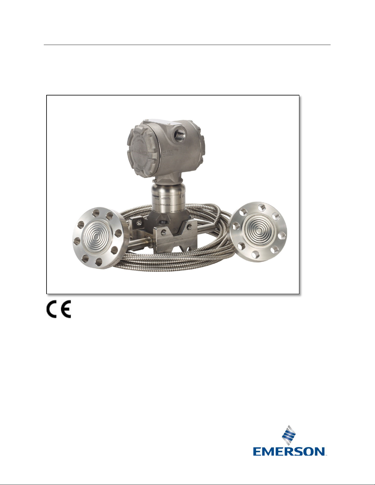
Rosemount 3159
Rosemount 3159 Nuclear Qualifi ed
Remote Diaphragm Seal
Page 2

This page intentionally left blank
Page 3
Reference Manual
00809-0100-4859 Rev AB
August 2017
Rosemount 3159
Title Page
iii
NOTICE
Read this manual before working with the product. For personal and system safety, and for optimum
Chan.RNII-CustomerFeedback@Emerson.com
Rosemount 3159 Remote Diaphragm Seal
performance, make sure you thoroughly understand the contents of this manual before installing, using
or maintaining this product.
For Assistance:
Within the United States, contact Rosemount Nuclear Instruments, Inc. (RNII) at
1-952-949-5210.
Outside the United States, contact the nearest Rosemount representative.
Customer Feedback:
Your feedback is important to us, please send comments or suggestions to:
Rosemount Nuclear Instruments, Inc. satisfies all obligations coming from legislation to
harmonize product requirements in the European Union
Page 4

Rosemount 3159
Reference Manual
00809-0100-4859 Rev AB
August 2017
iv
Title Page
RETURN OF MATERIAL
Authorization for return is required from Rosemount Nuclear Instruments, Inc. prior to shipment.
USA
IMPORTANT
The Nuclear Qualified Rosemount 3159 Remote Diaphragm Seal is designed for Nuclear Class 1E
for which the foregoing has not been complied with by the user.
Rosemount Nucl ear Instruments, I nc. Warranty and
Limitations of Remedy
The warranty and limitations of remedy applicable to this Rosemount equipment are as stated on the
reverse side of the current Rosemount quotation and customer acknowledgment forms.
Contact Rosemount Nuclear Instruments, Inc. (1-952-949-5210) for details on obtaining Return
Material Authorization (RMA). Rosemount Nuclear Instruments, Inc. will not accept any returned
material without a Return Material Authorization. Material returned without authorization is subject
to return to customer.
Material returned for repair, whether in or out of warranty, should be shipped prepaid to:
Rosemount Nuclear Instruments, Inc.
8200 Market Boulevard
Chanhassen, MN 55317
usage, and has been tested to the standards shown below:
• IEEE Std 323
• IEEE Std 344
Rosemount 3159 Remote Diaphragm Seals are manufactured under a quality system that meets the
requirements of ISO 9001, 10CFR50 Appendix B, ASME NQA-1, CSA Z299.1 and the applicable
portions of IAEA-50-C-Q. During qualification testing, interfaces were defined between
transmitter/remote seal system and the surrounding environment that are essential to meeting
requirements of the qualification standards listed above. Specifically, to ensure compliance with
10CFR Part 21, the transmitter/remote seal system must comply with the requirements herein and in
the applicable Rosemount qualification report(s) throughout its installation, opera t ion and m aintena nc e.
It is incumbent upon the user to ensure that Rosemount Nuclear Instruments, Inc.’s component
traceability program is continued throughout the life of the equipment.
In order to maintain the qualified status of the transmitter/remote seal system, the essential
environmental interfaces must not be compromised. Performance of any operations on the remote
seal system other than those specifically authorized in this manual has the potential for compromising
an essential environmental interface. Where the manual uses the terms requirement, man d atory,
must or required, the instructions so re fer enced must be carefully followed. Rosemount Nuclear
Instruments, Inc. expressly disclaims all responsibility and liability for transmitter/remote seal systems
TM
-1974/1983/2003
TM
-1975/1987/2004
Page 5

Reference Manual
00809-0100-4859 Rev AB
August 2017
Rosemount 3159
Title Page
v
Page
(Re v AA)
Page
(Rev AB)
Document revision change from October 2012 Rev AA to August 2017 Rev
regarding the 3159 Remote Seal qualification program.
2-2
4
Updated Figure 2-2 to depict current capillary support tube.
NA
5
Added Figure 2-3.
2-3
6
Added information on Temperature Head Effects.
3-4
11
Updated Figure 3-1 to depict current capillary support tube.
Updated Remote Seal / Lower Housing Assembly Procedure to include
instructions for installing Rosemount spares kit P/N 03159-5904-0003.
Updated Table 5-1 to include all current Rosemount Spares Kits for the 3159
Remote Seal.
NOTE
complete comparison deta il s .
Revision Status
Changes from October 2012 (Rev AA) to August 2017 (Rev. AB)
Changes
Cover,
throughout
3-3 – 3-4 10 – 13
5-1 19
The above Revision Status list summarizes the changes made. Please refer to both manuals for
Cover,
throughout
AB, updated document formatting, and removed outdated information
Page 6

Rosemount 3159
Reference Manual
00809-0100-4859 Rev AB
August 2017
vi
Title Page
This page intentionally left blank
Page 7

Reference Manual
00809-0100-4859 Rev AB
August 2017
Rosemount 3159
SECTION 1
Using this Manual.....................................................................................
1
Introduction
SECTION 2
Overview...................................................................................................
3
Performance
Remote Seal System................................................................................
3
Understanding Seal Syste m Performance........... .....................................
5
Temperature Effects....................................................................
6
System Time Response...............................................................
6
Static Head Effects......................................................................
6
Temperature Head Effects...........................................................
6
SECTION 3
Overview...................................................................................................
8
Installation
Safety Messages................ ......... ....... ...... ....... ...... ....... .. ......... .. ...............
8
Remote Seal Handling Considerations.....................................................
8
Remote Seal Installation Considerations..................................................
9
Remote Seal / Lower Housing Assembly Procedure................................
10
Installation of Capillary Clamps................................................................
13
SECTION 4
Overview...................................................................................................
15
Maintenance
Safety Messages................ ......... ....... ...... ....... ...... ....... .. ......... .................
15
General Considerations............................................................................
16
Metal Gasket Replacement......................................................................
15
SECTION 5
Overview...................................................................................................
18
Remote Seal
Spare Parts
Safety Messages................ ......... ....... ...... ....... ..................................... ....
18
18
Table of Contents
Spare Parts Ordering Information.............................................................
Page 8

Rosemount 3159
Reference Manual
00809-0100-4859 Rev AB
August 2017
viii
Contents
This page intentionally left blank
Page 9

Reference Manual
00809-0100-4859 Rev AB
August 2017
Rosemount 3159
SECTION 1:
Introduction
USING THIS MANUAL
This manual is designed to assist in installing, operating, and
leg reference is required.
NOTE
manual in conjunction with the transmitter reference manual.
maintaining the Rosemount 3159 Remote Diaphragm Seal.
The manual contains supplemental information about the
remote seal assemblies that are not covered in the
corresponding transmitter manuals.
The information is organized into the following categories:
Section 2: Performance
Explains key drivers of functional performance.
Section 3: Installation
Provides mechanical installation considerations of the remote
seal system.
Section 4: Maintenance
Provides basic hardware maintenance considerations for the
3159 remote seal.
Section 5: Spare Parts Ordering Information
Lists available spares kits.
The Rosemount 3159 Remote Diaphragm Seal is intended for
use in nuclear power stations where stringent quality control of
design and manufacturing processes is necessary to ensure
high reliability over an extended service life. The 3159 remote
seal can be supplied with all Rosemount 3150 Series nuclear
pressure transmitters.
Uses for the remote seal include applications where the
environment is unsuitable for instrumentation or where a wet
Refer to Rosemount Qualification/Test Reports and Product
Data Sheets for details on testing, performance specifications
and dimensional drawings.
Installation, operation, maintenance, and warranty information
for Rosemount 3150 Series nuclear pressure transmitters can
be found in the applicable reference manual. This
supplemental manual provides information regarding the use
of the Rosemount 3159 Remote Diaphragm Seal. Use this
Page 10

Rosemount 3159
Reference Manual
00809-0100-4859 Rev AB
August 2017
2
Introduction
This page intentionally left blank
Page 11

Reference Manual
00809-0100-4859 Rev AB
August 2017
Rosemount 3159
SECTION 2:
Performance
Overview................................................................
page 3
Remote Seal System.............................................
page 3
Understanding Seal System Performance..........
Page 5
OVERVIEW
This section contains the following considerations:
→ Temperature Head Effects
REMOTE SEAL SYSTEM
A remote seal system consists of a pressure transmitter, a
electronically to a 4-20 mA output signal.
Figure 2-1 Rosemount 3159 Exploded
View
• Remote Seal System
• Understanding Seal Syste m Performance
→ Temperature Effects
→ System Time Response
→ Static Head Effects
remote seal, and a capillary assembly filled with a secondary
fill fluid.
During operation, the thin, flexible diaphragm and remote seal
fill fluid separate the pressure sensor of the transmitter from
the process medium. The capillary tubing connects the
diaphragm to the transmitter.
When process pressure is applied, the diaphragm is
displaced, transferring the measured pressure through the
filled system, by way of the capillary tubing, to the transmitter.
This transferred pressure displaces the sensing diaphragm in
the pressure sensor of the transmitter. This displacement is
proportional to the process pressure and is converted
Page 12

Rosemount 3159
Reference Manual
00809-0100-4859 Rev AB
August 2017
4
Performance
Figure 2-2 – Rosemount 3159
Dimensions
NOTE: All dimensions are nominal in inches (millimeters)
Remote Seal / Lower Housing
Page 13

Reference Manual
00809-0100-4859 Rev AB
August 2017
Rosemount 3159
Performance
5
Figure 2-3 – Rosemount 3159
S0201 Special Option Dimensio ns
NOTE: All dimensions are nominal in inches (millimeters)
UNDERSTANDING SEAL
The performance of a remote diaphragm seal is determined by
Rosemount 3159 Product Data Sheet.
Remote Seal / Lower Housing with
SYSTEM PERFORMANCE
how accurately a pressure signal is transferred from the
remote seal isolator diaphragm to the transmitter sensor.
Remote seal performance is characterized by:
• Temperature Effects
• System Time Response
• Static Head Effects
• Temperature Head Effects
Remote seal performance specifications are published in the
Page 14

Rosemount 3159
Reference Manual
00809-0100-4859 Rev AB
August 2017
6
Performance
Temperature Effects
Changes in ambient temperature cause changes in fill fluid
(one-sided versus two-sided).
System Time Response
The time response of a system is dependent on the
requirement.
Static Head Effects
If the diaphragm seal and transmitter are installed at different
additional information.
Temperature Head Effects
Changes in ambient temperature also cause changes in the fill
by the transmitter as a change in pressure.
volume relative to the metallic capillary system. To an extent,
changes in fill fluid volume are accommodated by the remote
seal diaphragm, whose spring rate is much less than that of
the transmitter isolator diaphragm. However, some of the
temperature-induced vo lum e change is seen as back pressure
at the transmitter, which creates a shift in transmitter output.
Temperature effects errors are usually smaller for symmetric
systems, since the back pressure is more similar on high and
low sides.
Factors that affect remote seal temperature effects
performance include capillary length, fill fluid and configuration
transmitter model, its sensor range, the length and inner
diameter (ID) of the capillary, and the viscosity of the fill fluid
(which is directly affected by the process and ambient
temperatures). These factors all play a role in the overall
performance of any seal system.
For high viscosity fill fluids, capillary length should be kept to a
minimum if system time response is an important performance
elevations, a zero shift occurs due to static head effects. The
zero shift can be removed by re-zeroing the transmitter after
installation.
However, static head effects create restrictions on installation.
When the transmitter and remote seals are installed at
different heights, the limitations of the transmitter capability for
zero suppression and zero elevation must be considered. The
applicable 3150 Series Pressure Transmitter Product Data
Sheets define the zero suppression and zero elevation
capability of each pressure range. Please contact RNII for
fluid specific gravity. Changes in fill fluid specific gravity affect
the weight of the fill fluid column acting on the sensor.
At reference conditions, the weight of the fill fluid column will
produce a zero shift, which can be removed by re-zeroing the
transmitter (static head effect). As ambient temperature
changes, the fill fluid specific gravity changes which, in turn,
changes the weight of the fill fluid column. This will be seen
Page 15

Reference Manual
00809-0100-4859 Rev AB
August 2017
Rosemount 3159
Performance
7
This page intentionally left blank
Page 16

Rosemount 3159
Reference Manual
00809-0100-4859 Rev AB
August 2017
SECTION 3:
Installation
Overview.................................................................
page 8
Safety Messages....................................................
page 8
Remote Seal Handling Considerations................
page 8
Remote Seal Installation Considerations............
page 9
Remote Seal / Lower Housing Assembly
Procedure...............................................................
Page 10
Installation of Capillary Clamps............................
Page 13
OVERVIEW
This section contains the following installation considerations:
• Installation of Capillary Clamps
SAFETY MESSAGES
Procedures and instructions in this section may require special
performing an operation preceded by this symbol:
Warnings
WARNING
Never attempt to disconnect the remote seal flange from the
the product warranty.
REMOTE SEAL HANDLING
Diaphragm seals are relatively delicate and should be handled
false reading.
• Remote Seal Handling Considerations
• Remote Seal Installation Considerations
• Remote Seal / Lower Housing Assembly Procedure
precautions to ensure the safety of the personnel performing
the operation. Refer to the following safety messages before
transmitter. Doing so will result in loss of fill fluid and will void
CONSIDERATIONS
with care.
Do not lift the seal or transmitter by gripping the capillaries
when unpacking or handling a transmitter / remote seal
system. Avoid sharply bending or crimping capillary tubing.
The minimum bending radius of the capillary tubing is 3 in (8
cm).
The protective cover should remain on the seal until the
moment before installation. Avoid touching the diaphragm
with fingers or objects and refrain from setting the diaphragm
side of the seal down on a hard surface. Even minor dents or
scratches in the diaphragm material may impair the
performance of the remote seal system.
When installing the remote seal system, make sure the gasket
is aligned properly on the gasket sealing surface. Failure to
properly install the gasket may cause process leaks, which
can result in death or serious injury. In addition, make sure
the gasket does not press down upon the diaphragm face.
Anything pressing on the diaphragm will be read by the
transmitter as pressure. A misaligned gasket may cause a
Page 17

Reference Manual
00809-0100-4859 Rev AB
August 2017
Rosemount 3159
Installation
9
REMOTE SEAL
Rosemount 3159 remote seal is qualified for liquid and gas
a constant ambient temperature.
INSTALLATION
CONSIDERATIONS
service. As much as possible, the process medium should be
free of solids, since these could potentially clog the process
pipe connection or accumulate over time in the cavity on the
process side of the diaphragm. Care should be exercised in
making sure that the process fluid does not become overly
viscous or freeze in the process pipe connection or seal
cavity.
The maximum working pressure depends on the transmitter
pressure range, pressure measurement type, and remote seal
bolting option (B1 or B2). Use the applicable Rosemount
3150 Series Pressure Transmitter Product Data Sheet along
with the Rosemount 3159 Remot e Seal Product D ata She et to
determine maximum working pressure. Please contact RNII
for additional information.
The lower housing is available with four different process
connections: 1/4 inch NPT, 1/2 inch NPT, 1 inch NPT and 1
inch socket weld. The customer is responsible for making a
qualified connection to the process piping. The lower housing
includes one or two 1/4-18 NPT flushing connection(s) so that
the cavity under the diaphragm can be bled or flushed while
the unit is in service. See Figure 2-2 or Figure 2-3 for details.
Due to the many possible mounting configurations,
Rosemount does not provide a qualified remote seal mounting
bracket. Mounting of the remote seal is the responsibil it y of
the customer. The applicable Rosemount qualification report
describes the mounting configurations used during
qualification testing.
Due to pressure head effects, there are limits to the allowable
elevation difference between remote seals and 3150 Series
pressure transmitters. These limits are a function of the
remote seal fill fluid type, the fill fluid specific gravity and
transmitter range code. In no case should the difference in
height between a transmitter and seal or between two seals
exceed the upper range limit of the transmitter. Best practice
is to mount the transmitter at or below the lower process tap if
possible.
If the diaphragm seal and transmitter are installed at different
elevations, a zero shift occurs due to static head effects. The
zero shift can be removed by re-zeroing the transmitter after
installation.
Changes in process and ambient temperatures can result in
changes in transmitter zero output. Temperature-induced
errors can be minimized by heat tracing the capillary to ensure
Page 18

Rosemount 3159
Reference Manual
00809-0100-4859 Rev AB
August 2017
10
Installation
Special precautions must be taken to prevent damage to
from boiling. Refer to steam tables for required pressures.
IMPORTANT
Care must be taken under all circumstances to ensure the fill
fluid vapor pressure is not exceeded.
REMOTE SEAL / LOWER
PROCEDURE
IMPORTANT
Tools required for assembly of the 3159 Remote Seal / Lower
questions regarding the required tools.
Table 3-1 – Tools Required for
Assembly
Description
Rosemount Part Number
Photo
Vice or holding fixture
Customer Supplied
No photo available
capillary systems filled with distilled water. Distilled water
should not be exposed to operating temperatures below 40°F
(4.4°C); when exposed to operating temperatures above
180°F (82.2°C), application of static pressure to the remote
seal is conservatively recommended to prevent the fill fluid
HOUSING ASSEMBLY
Take care during the assembly process to prevent possible
damage to the isolator diaphragm or metal gasket.
Housing can be found in Table 3-1. If a Rosemount part
number is not specified, any general brand tool that meets the
specifications can be used. Please contact RNII with any
Remote Seal / Lower Housing
3/4-inch Open-ended Wrench Customer Supplied
3/4-inch Socket Adjustable
Torque Wrench
Customer Supplied
Page 19

Reference Manual
00809-0100-4859 Rev AB
August 2017
Rosemount 3159
Installation
11
1. Disassemble remote seal / lower housing if
NOTE
tight, then a new metal gasket must be installed.
NOTE
details.
NOTE
details.
NOTE
Table 3-2.
Figure 3-1 – B2 Option Bolt Detail
necessary.
If the metal gasket was installed between the remote seal
and lower housing and bolts were torqued beyond finger
2. Gently clean the remote seal isolator diaphragm,
lower housing and metal gasket with a clean cloth.
3. Center the metal gasket on the lower housing.
4. Carefully place the remote seal on top of the lower
housing and metal seal, taking care to align the bolt
holes.
5. Install eight bolts from the remote seal side.
For B2 option rotate bolts to ensure the heads are “locked”
against the remote seal center hub. See Figure 3-1 for
When installing bolts provided with Rosemount spare kit
P/N 03159-5904-0003, insert four 3.25-inch bolts from the
remote seal side and four 2.5-inch bolts from the lower
housing side in an alternating pattern. See Figure 3-2 for
6. Install eight nuts hand tight.
7. Tighten the eight nuts using the crossing pattern
shown in Figure 3-3 and according to the torque
sequence and values shown in Table 3-2.
When installing bolts provided with Rosemount spare kit
P/N 03159-5904-0003, tighten the eight nuts using the
crossing pattern shown in Figure 3-4 and according to the
torque sequence and values for the B2 Option shown in
Page 20

Rosemount 3159
Reference Manual
August 2017
12
Installation
Figure 3-2 – Rosemount Spares Kit
Detail
Figure 3-3 – Bolt Torqueing Pattern
Figure 3-4 – Torqueing Pattern for
Spares Kit P/N 03159-5904-0003
P/N 03159-5904-0003 Bo lt Inst allat ion
00809-0100-4859 Rev AB
Bolts Provided with Rosemount
Page 21

Reference Manual
00809-0100-4859 Rev AB
August 2017
Rosemount 3159
Installation
13
Table 3-2 – Torqueing Sequence for
B1 and B2 Options
Torque Value
B1
B2
(1)
1
150 in-lb (16.9 N-m)
220 in-lb (24.9 N-m)
2
300 in-lb (33.9 N-m)
440 in-lb (49.7 N-m)
3
450 in-lb (50.8 N-m)
660 in-lb (74.6 N-m)
4
600 in-lb (67.8 N-m)
875 in-lb (98.9 N-m)
5
600 in-lb (67.8 N-m)
875 in-lb (98.9 N-m)
(2)
6
600 in-lb (67.8 N-m)
(2)
--
Notes:
(2) T orque tolerance for this step is ±5%.
INSTALLATION OF
Clamps (Rosemount spare kit P/N 03159-5902-0001 or
(8 cm).
Step
(1) Use B2 torque sequence and values when installing bolts provided with Rosemount spares kit P/N 03159-5904-0003.
CAPILLARY CLAMPS
equivalent) should be placed approximately 18 inches (46 cm)
apart to hold the capillary tubing in place, using any standard
grade 1/4-20 screw.
The minimum bending radius of the capillary tubing is 3 inches
Page 22

Rosemount 3159
Reference Manual
00809-0100-4859 Rev AB
August 2017
14
Installation
This page intentionally left blank
Page 23

Reference Manual
00809-0100-4859 Rev AB
August 2017
Rosemount 3159
SECTION 4:
Maintenance
Overview.................................................................
page 15
Safety Messages....................................................
page 15
General Considerations.........................................
page 16
Metal Gasket Replacement....................................
page 16
OVERVIEW
This section contains the following maintenance
• Metal Gasket Replacement
SAFETY MESSAGES
Procedures and instructions in this section may require special
performing an operation preceded by this symbol:
Warnings
WARNING
Replacement equipment or spare parts not approved by
Instruments, Inc. as spare parts for the 3159.
WARNING
Remote seal systems are factory filled systems that cannot be
seal system assembly and voids the product warranty.
WARNING
Residual process fluid may remain after disassembly of lower
appropriate safety measures.
WARNING
Process leaks could result in death or serious injury.
while the remote seal is in service.
NOTE
beginning of this manual preceding Section 1).
considerations:
• General Considerations
precautions to ensure the safety of the personnel performing
the operation. Refer to the following safety messages before
Rosemount Nuclear Instruments, Inc. for use could reduce the
performance capabilities of the remote seal system and may
render the instrument dangerous or adversely impact its
qualified status.
• Use only components supplied with the 3159 Remote
Seal or designated by Rosem ount Nucle ar
refilled in the field. Do not attempt to disconnect the seals or
capillaries from the transmitter. Doing so can damage the
housing. If this fluid is potentially contaminated, take
• Install and tighten all eight remote seal bolts before
applying pressure
• Do not attempt to loosen or remove remote seal bolts
Maintenance of traceability of any replacement parts is the
responsibility of the user (see Important Notice at the
Page 24

Rosemount 3159
Reference Manual
00809-0100-4859 Rev AB
August 2017
16
Maintenance
GENERAL
Once installed, the Rosemount 3159 Remote Seal is generally
guidance.
METAL GASKET
Use the following steps to replace the metal gasket:
procedure shown in Section 3: Installation.
NOTE
followed whenever the remote seal is disassembled.
CONSIDERATIONS
REPLACEMENT
considered to be a maintenance-free component. In cases
where maintenance is required, this section provides
1. Remove the remote seal from service.
2. Disassemble the remote seal / lower housing and
discard metal gasket.
3. Follow the remote seal / lower housing assembly
The procedure for replacement of the metal gasket must be
Page 25

Reference Manual
00809-0100-4859 Rev AB
August 2017
Rosemount 3159
Maintenance
17
his page intentionally left blank
T
Page 26

Rosemount 3159
Reference Manual
00809-0100-4859 Rev AB
August 2017
SECTION 5:
Remote Seal Spare Par ts
Overview.................................................................
page 18
Safety Messages....................................................
page 18
Spare Parts Ordering Information........................
page 18
OVERVIEW
This section contains the following topics:
• Spare Parts Ordering Information
SAFETY MESSAGES
Procedures and instructions in this section may require special
performing an operation preceded by this symbol:
WARNING
Replacement equipment or spare parts not approved by
Instruments, Inc. as spare parts for the 3159.
NOTE
beginning of this manual preceding Section 1).
SPARE PARTS ORDERING
INFORMATION
Table 5-1 contains part numbers used for ordering spare parts
precautions to ensure the safety of the personnel performing
the operation. Refer to the following safety messages before
Rosemount Nuclear Instruments, Inc. for use could reduce the
performance capabilities of the remote seal system and may
render the instrument dangerous or adversely impact its
qualified status.
• Use only components supplied with the 3159 Remote
Seal or designated by Rosem ount Nucle ar
Maintenance of traceability of any replacement parts is the
responsibility of the user (see Important Notice at the
for the 3159 Remote Seal.
Page 27

Reference Manual
00809-0100-4859 Rev AB
August 2017
Rosemount 3159
Remote Seal Spare Parts
19
Table 5-1 – Rosemount 3159 Spare
Parts
Rosemount
Part Number
03159-5901-0001
Metal Gasket (Remote Seal / Lower Housing Interface) (Qty=1)
--
03159-5902-0001
Capillary Clamp (Qty=1)
--
03159-5903-0001
Lower Housing, 1/4-inch NPT, One Flushing Connection (Qty=1)
P1
03159-5903-0002
Lower Housing, 1/2-inch NPT, One Flushing Connection (Qty=1)
P2
03159-5903-0003
Lower Housing, 1-inch NPT, One Flushing C onn ec tio n (Q t y=1)
P3
Lower Housing, 1-inch Socket Weld, One Flushing Connection
(Qty=1)
03159-5903-0005
Lower Housing,1/4-inch NPT, Two Flushing Connections (Qty=1)
P5
03159-5903-0006
Lower Housing, 1/2-inch NPT, Two Flushing Connections (Qty=1)
P6
03159-5903-0007
Lower Housing, 1-inch NPT, Two Flushing Connections (Qty=1)
P7
Lower Housing, 1-inch Socket Weld, Two Flushing Connections
(Qty=1)
03159-5904-0001
Nut & Bolt, 2.5-inch, Standard Head (Qty=8)
B1
03159-5904-0002
Nut & Bolt, 2.5-inch, Heavy Hex Head (Qty=8)
B2
03159-5904-0003
Nut & Bolt, 2.5-inch & 3.25-inch, Heavy Hex Head (Qty=4 ea.)
--
Spares Kit
03159-5903-0004
03159-5903-0008
Description
3159 Model
Code Option
P4
P8
Page 28

Rosemount 3159
Global Headquarters
RNII.info@Emerson.com
Standard Terms and Conditions of Sale can be found at:
© 2017 Emerson Automation Solutions. All rights reserved.
Std 323 and Std 344 are registered trademarks of IEEE
Rosemount Nuclear Instruments, Inc. satisfies
European Union.
Reference Manual
00809-0100-4859 Rev AB
August 2017
Emerson Automation Solutions
Rosemount Nuclear Instruments, Inc.
8200 Market Blvd.
Chanhassen, MN 55317, USA
P +1 952 949-5210
F +1 952 949-5201
www.Emerson.com/en-us/pages/Terms-of-Use.aspx
merson logo is a trademark and service mark of
The E
Emerson Electric Co.
Rosemount and Rosemount logotype are trademarks of
Rosemount Inc.
All other marks are the property of their respective owners
all obligations coming from legislation to
harmonize product requirements in the
 Loading...