

Page 1
Reference Manual
00809-0100-4835 Rev BD
July 2016
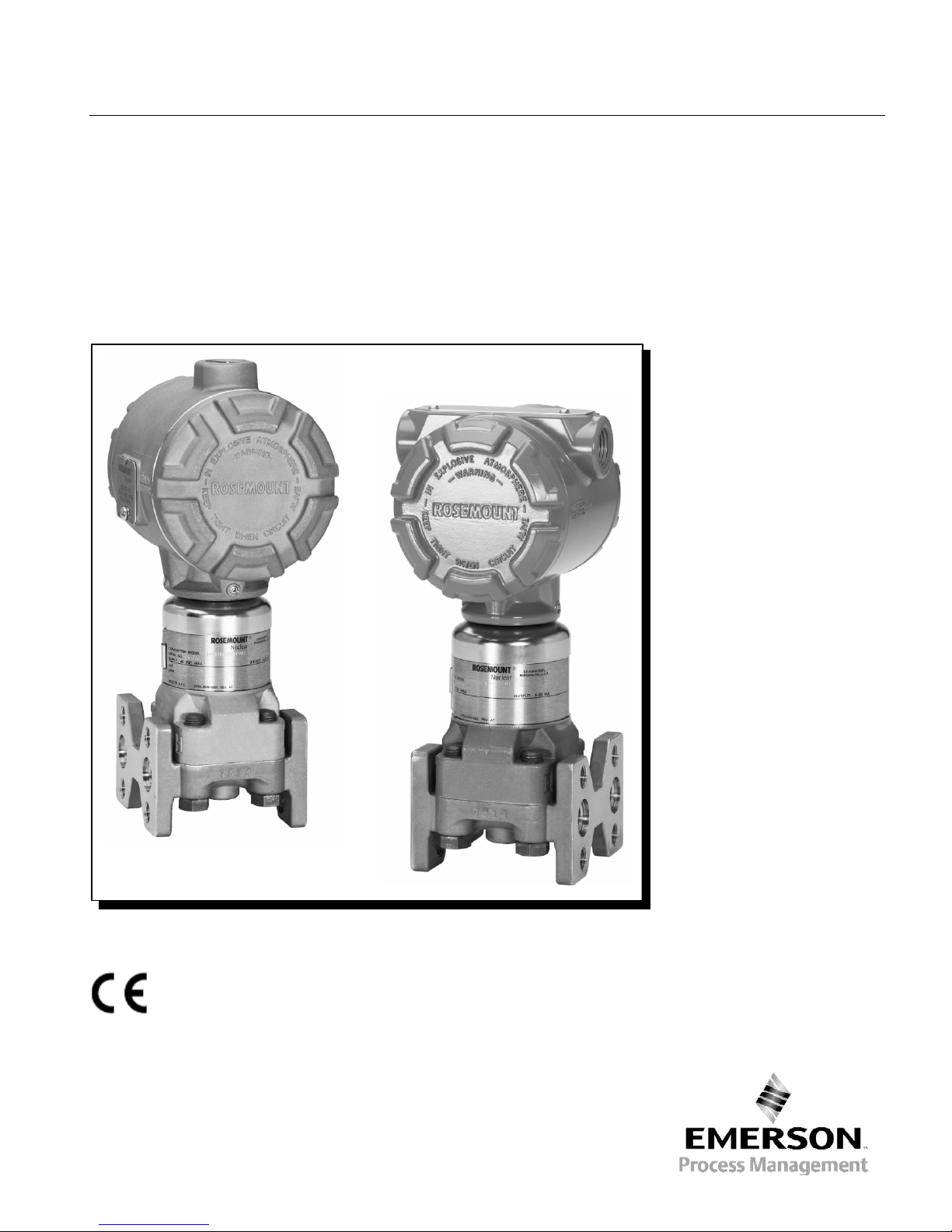
Rosemount 3150 Series Nuclear Pressure
Transmitters including the Rosemount
3152, 3153 and 3154
Page 2

Page 3

Reference Manual
00809-0100-4835 Rev BD
July 2016
Rosemount 3150 Series
NOTICE
Rosemount Nuclear Instruments, Inc. satisfies all obligations
Rosemount 3150 Series Nuclear Pressur e Transmitters
including the Rosemount 3152, 3153 and 3154
Read this manual before working with the product. For personal and system
safety, and for optimum performance, make sure you thoroughly understand the
contents of this manual before installing, using or maintaining this product.
For Assistance:
Within the United States, contact Rosemount Nuclear Instruments, Inc. at
1-952-949-5210.
Outside the United States, contact the nearest Rosemount representative.
Customer Feedback:
Your feedback is important to us, please send comments or suggestions to:
Chan.RNII-CustomerFeedback@emersonprocess.com
coming from legislation to harmonize product requirements in
the European Union.
i
Page 4

Rosemount 3150 Series
Reference Manual
00809-0100-4835 Rev BD
July 2016
Rosemount Nucl ear Instruments, I nc. Warranty and
Limitations of Remedy
The warranty and limitations of remedy applicable to this Rosemount equipment are as stated on the reverse
side of the current Rosemount quotation and customer acknowledgment forms.
RETURN OF MATERIAL
Authorization for return is required from Rosemount Nuclear Instruments, Inc. prior to shipment. Contact
Rosemount Nuclear Instruments, Inc. (1-952-949-5210) for details on obtaining Return Material Authorization
(RMA). Rosemount Nuclear Instruments will not accept any returned materi al without a Return
Material Authorization. Material returned without authorization is subject to return to customer.
Material returned for repair, whether in or out of warranty, should be shipped prepaid to:
Rosemount Nuclear Instruments, Inc.
8200 Market Boulevard
Chanhassen, MN 55317
USA
IMPORTANT
Rosemount 3152, 3153 and 3154 Series Pressure Transmitters are designed for Nuclear Class 1E usage, and
have been tested to the standards shown below:
• IEEE Std 323™-1974, -1983 and -2003
• IEEE Std 344™-1975, -1987 and -2004
These transmitters are manufactured under a quality system that meets the requirements of 10CFR50
Appendix B, 10CFR Part 21, ISO 9001, NQA-1, KTA 1401, KTA 3507, CSA N285.0, CSA Z299 and the
applicable portions of IAEA-50-C-Q. During qualification testing, interfaces were defined between the
transmitter and its environment that are essential to meeting requirements of the qualification standards listed
above. Specifically, to ensure compliance with 10CFR Part 21, the transmitter must comply with the
requirements herein and in the applicable Rosemount qualification report(s) throughout its installation,
operation and maintenance. It is incumbent upon the user to ensure that the Rosemount Nuclear Instruments,
Inc.’s component traceability program is continued throughout the life of the transmitter.
In order to maintain the qualified status of the transmitter, the essential environmental interfaces must not be
compromised. Performance of any operations on the transmitter other than those specifically authorized in
this manual has the potential for compromising an essential environmental interface. Where the manual
uses the terms requirement, mandatory, must or required, the instructions so referenced must be
carefully followed. Rosemount Nuclear Instruments, Inc. expressly disclaims all responsibility and liability for
transmitters for which the foregoing has not been complied with by the user.
• RCC-E-2002
• KTA 3505-2005
ii
Page 5

Reference Manual
00809-0100-4835 Rev BD
July 2016
Rosemount 3150 Series
Cover,
throughout
Cover,
throughout
Throughout
Throughout
Updated references and terminology for consistency throughout document.
Minimum time constant for damping adjustment set to maximum position for
3153 and 3154 transmitters (output code T) changed from 0.8 sec to 1.2 sec.
Relocated step 2 in the Preliminary Electric al Housing Reassembly Section to
the Electronics Housing Cover Installation Section and revised for clarity.
Updated Electronics Assembly Installation procedure to include additional
instruction for installing the connector plug.
Added Figure 5-7 – Connector Plug Detail and updated subsequent figure and
page numbers accordingly.
NOTE
The above Revision Status list summarizes the changes made. Please refer to both manuals for complete
comparison details.
Revision Status
Changes from March 2015 (Rev BC) to July 2016 (Rev BD)
Page
(Rev BC)
3-11 3-11
5-11 & 5-13 5-11 & 5-14
5-12 5-12
5-12 to 5-18 5-12 to 5-19
Page
(Rev BD)
Changes
Document revision change from March 2015 to July 2016, Rev BC to Rev BD
iii
Page 6

Rosemount 3150 Series
Reference Manual
00809-0100-4835 Rev BD
July 2016
iv
Page 7

Reference Manual
00809-0100-4835 Rev BD
July 2016
Rosemount 3150 Series
SECTION 1
Using this Manual. . . . . . . . . . . . . . . . . . . . . . . . . . . . . . . . . . . . . . . . .
. . .1-1
SECTION 2
Overview . . . . . . . . . . . . . . . . . . . . . . . . . . . . . . . . . . . . . . . . . . . . . . .
Safety Messages . . . . . . . . . . . . . . . . . . . . . . . . . . . . . . . . . . . . . . . . .
General Considerations. . . . . . . . . . . . . . . . . . . . . . . . . . . . . .
Mechanical Considerations . . . . . . . . . . . . . . . . . . . . . . . . . . . . . . . . .
Electrical Considerations . . . . . . . . . . . . . . . . . . . . . . . . . . . . . . . . . . .
Installation Procedures. . . . . . . . . . . . . . . . . . . . . . . . . . . . . . . . . . . . .
. . . 2-1
SECTION 3
Overview . . . . . . . . . . . . . . . . . . . . . . . . . . . . . . . . . . . . . . . . . . . . . . .
Safety Messages. . . . . . . . . . . .
Calibration Overview . . . . . . . . . . . . . . . . . . . . . . . . . . . . . . . . . . . . . .
Calibration Procedures
Zero DP). . . . . . . . . . . . . . . . . . . . . . . . . . . . . . . . . . .
Procedure. . . . . . . . . . . . . . . . . . . . . . . . . . . . . . . . . .
. . . . . . . . . . . . .
Code 4 and 5 DP Transmitters. . . . . . . . . . . . . . . . . .
Transmitters (All Ranges). . . . . . . . . . . . . . . . . . . . . .
. . .3-1
1
Introduction
Table of Contents
Installation
Process Connections and Interfaces . . . . . . . . . . . . . . . . . . .
Impulse Piping . . . . . . . . . . . . . . . . . . . . . . . . . . . . . . . . . . . .
Mounting Configurations. . . . . . . . . . . . . . . . . . . . . . . . . . . . .
Conduit . . . . . . . . . . . . . . . . . . . . . . . . . . . . . . . . . . . . . . . . . .
Electrical Housing . . . . . . . . . . . . . . . . . . . . . . . . . . . . . . . . . .
Mechanical – Transmitter . . . . . . . . . . . . . . . . . . . . . . . . . . . .
Mechanical – Conduit . . . . . . . . . . . . . . . . . . . . . . . . . . . . . . .
Electrical . . . . . . . . . . . . . . . . . . . . . . . . . . . . . . . . . . . . . . . . .
Calibration
Calibration Considerations . . . . . . . . . . . . . . . . . . . . . . . . . . .
Definitions. . . . . . . . . . . . . . . . . . . . . . . . . . . . . . . . . . . . . . . .
Span Adjustment Range. . . . . . . . . . . . . . . . . . . . . . . . . . . . .
Zero Adjustment Range . . . . . . . . . . . . . . . . . . . . . . . . . . . . .
Span and Zero Adjustment . . . . . . . . . . . . . . . . . . . . . . . . . . .
Calibration Procedure for Zero Based Span (LRV is
Damping Adjustment. . . . . . . . . . . . . . . . . . . . . . . . . . . . . . . .
Correction for High Static Line Pressure. . . .
Linearity. . . . . . . . . . . . . . . . . . . . . . . . . . . . . . . . . . . . . . . . . .
Calibration Procedure for Elevated or Suppressed
Zero . . . . . . . . . . . . . . . . . . . . . . . . . . . . . . . . . . . . . .
Coarse Zero Select Jumper Position Selection
High Static Pressure Span Effect on Range Codes
1, 2 and 3 DP Transmitters . . . . . . . . . . . . . . . . . . . .
High Static Pressure Span Correction for Range
High Static Line Pressure Zero Correction for DP
. . . . . . . . . . . . . . . . . . . . . . . . . . . . .
. . . . . . . . . . . . . . . . . . . . . . . . . . . . . . . . . . . .
. . . . . .
. . .2-1
. . . 2-2
. . . 2-2
. . . 2-3
. . . 2-4
. . . 2-5
. . . 2-6
. . . 2-6
. . . 2-7
. . 2-10
. . 2-10
. . 2-14
. . 2-14
. . . 3. . . 3-2
. . . 3-2
. . . 3-3
. . . 3-5
. . . 3-5
. . .3-6
. . .3-6
. . .3-6
. . . 3-7
. . 3-10
. . 3-11
. . 3-12
. . 3-12
. . 3-12
. . 3-17
. . 3-17
Page 8

Rosemount 3150 Series
Reference Manual
00809-0100-4835 Rev BD
July 2016
SECTION 4
Overview . . . . . . . . . . . . . . . . . . . . . . . . . . . . . . . . . . . . . . . . . . . . . . .
Transmitter Theory of Operation . . . . . . . . . . . . . . . . . . . . . . . . . . . . .
The Sensor Cell. . . . . . . . . . . . . . . . . . . . . . . .
Demodulator . . . . . . . . . . . . . . . . . . . . . . . . . . . . . . . . . . . . . . . . . . . .
Oscillator . . . . . . . . . . . . . . . . . . . . . . . . . . . . . . . . . . . . . . . . . . . . . . .
Voltage Reg
Current Control . . . . . . . . . . . . . . . . . . . . . . . . . . . . . . . . . . . . . . . . . .
Current Limit . . . . . . . . . . . . . . . . . . . . . . . . . . . .
Reverse Polarity Protection. . . . . . . . . . . . . . . . . . . . . . . . . . . . . . . . .
. . . 4-1
SECTION 5
Overview . . . . . . . . . . . . . . . . . . . . . . . . . . . . . . . . . . . . . . . . . . . . . . .
Safety Messages . . . . . . . . . . . . . . . . . . . . . . . . . . . . . . . . . . . . . . . . .
General Considerations. . . . . . . .
Test Terminal. . . . . . . . . . . . . . . . . . . . . . . . . . . . . . . . . . . . . . . . . . . .
Electronics Assembly Checkout. . . . . . . . . . . . . . . . . . . . . . . . . . . . . .
Sensor
Disassembly Procedure. . . . . . . . . . . . . . . . . . . . . . . . . . . . . . . . . . . .
Reassembly Procedure. . . . . . . . . . . . . . . . . . . . . . . . . . . . . . . . . . . . .
Post Assembly Tests. . . . . . . . . . . . . . . . . . . . . . . . . . . . . . . . . . . . . .
. . . 5-1
SECTION 6
Overview . . . . . . . . . . . . . . . . . . . . . . . . . . . . . . . . . . . . . . . . . . . . . . .
Safety Messages . . . . . . . . . . . . . . . . . . . . . . . . .
General Considerations
Spare Parts Shelf Life . . . . . . . . . . . . . . . . . . . . . . . . . . . . . . . . . . . . .
Impact on
Transmitter Spare Parts List . . . . . . . . . . . . . . . . . . . . . . . . . . . . . . . .
. . . 6-1
. . . 6-4
Operation
Maintenance and
Troubleshooting
Transmitter Spare Parts
. . . . . . . . . . . . . . . . . .
ulator . . . . . . . . . . . . . . . . . . . . . . . . . . . . . . . . . . . . . . . .
. . . . . . . . . . . . . . . .
. . . . . . . . . . . . . . . . . . . . . . . . . . . .
Module Checkout. . . . . . . . . . . . . . . . . . . . . . . . . . . . . . . . . . .
Process Flange Removal . . . . . . . . . . . . . . . . . . . . . . . . . . . .
Electrical Housing Disassembly . . . . . . . . . . . . . . . . . . . . . . .
Electrical Housing Reassembly . . . . . . . . . . . . . . . . . . . . . . .
Process Flange Reassembly . . . . . . . . . . . . . . . . . . . . . . . . .
. . . . . . . . . . . . . . . .
. . . . . . . . . . . . . . . . . . . . . . . . . . . . . . . . . . . .
Transmitter Qualified Life . . . . . . . . . . . . . . . . . . . . . . . . . .
. . . 4-2
. . . 4-3
. . . 4-4
. . . 4-5
. . . 4-5
. . . 4-5
. . . 4-5
. . . 4-5
. . . 5-1
. . . 5-3
. . . 5-5
. . . 5-5
. . . 5-6
. . . 5-7
. . . 5-7
. . . 5-8
. .5-11
. . 5-11
. . 5-14
. . 5-16
. . . 6-1
. . . 6-3
. . . 6-3
. . . 6-3
TOC-2
Page 9
Reference Manual
00809-0100-4835 Rev BD
July 2016
Rosemount 3150 Series
USING THIS MANUAL
This manual is designed to assist in installing, operating and
NOTE
Refer to the applicable Rosemount Qualification/Test Reports, Product
performance specifications and dimensional drawings for each model.
Unique Transmitter Serial Number
is stamped here
Transmitter Model Number is
stamped here
Factory Calibrated Span
is stamped here
Transmitter Maximum Power
Maximum Working
Pressure is stamped here
SECTION 1: INTRODUCTION
maintaining the Rosemount 3150 Series Pressure Transmitters.
Instructions for the 3152, 3 153 and 3154 models are included in this
manual. Where differences in instructions between the models occur
they shall be noted within those instructions. The manual is organized
into the following sections:
Data Sheets and/or Specification Drawings for details on testing,
Figure 1-1 shows the standard transmitter nameplate and where
transmitter information is stamped onto the nameplate. Nameplate
material is stainless steel.
Figure 1-1 – Standard Transmitter
Nameplate
Section 2: Installation
Provides general, mechanical, and electrical installation
considerations.
Section 3: Calibration
Provides transmitter calibration procedures.
Section 4: Operation
Provides a description of how the transmitter operates.
Section 5: Maintenance and Troubleshooting
Provides basic hardware troubleshooting considerations including
disassembly and reassembly procedures and post assembly tests.
Section 6: Transmitter Spare Pa rts
Provides order information for transmitter spare parts.
Supply Limit is stamped here
Page 10

Rosemount 3150 Series
Reference Manual
00809-0100-4835 Rev BD
July 2016
1-2
Page 11

Reference Manual
00809-0100-4835 Rev BD
July 2016
Rosemount 3150 Series
Overview. . . . . . . . . . . . . . . . . . . . . . . . . . . . . . . . . . . . . . .
Installation Procedures. . . . . . . . . . . . . . . . . . . . . . . . . . .
page 2-1
page 2-10
SAFETY MESSAGES
Procedures and instructions in this section may require special
an operation preceded by this symbol .
Warnings
WARNING
OVERVIEW
This section contains the following installation considerations:
o Electrical
SECTION 2: INSTALLATION
Safety Messages . . . . . . . . . . . . . . . . . . . . . . . . . . . . . . . .
General Considerations. . . . . . . . . . . . . . . . . . . . . . . . . . .
Mechanical Considerations. . . . . . . . . . . . . . . . . . . . . . . .
Electrical Considerations . . . . . . . . . . . . . . . . . . . . . . . . .
page 2-1
page 2-2
page 2-2
page 2-7
• General Considerations
• Mechanical Considerations
o Process Connections
o Impulse Piping
o Mounting Configurations
o Conduit
o Electrical Housing
• Electrical Considerations
• Installation Procedures
o Mechanical
precautions to ensure the safety of the personnel performing the
operation. Refer to the following safety messages before performing
Explosions can result in death or injury.
• Do not remove the transmitter covers in explosive
• Verify that the operating atmosphere of the transmitter is
environments when the circuit is live.
consistent with the appropriate qualification parameters.
Page 12

Rosemount 3150 Series
Reference Manual
00809-0100-4835 Rev BD
July 2016
WARNING
GENERAL
CONSIDERATIONS
Measurement accuracy depends upon proper installation of the
MECHANICAL
CONSIDERATIONS
This section contains information you should consider when preparing
WARNING
NOTE
For steam service, do not blow down impulse piping through the
lines with water before resuming measurement.
Electrical shock can result in death or serious injury.
• Avoid contact with the leads and terminals.
Process leaks could result in death or serious injury.
• Install and tighten all four flange bolts before applying
pressure.
• Do not attempt to loosen or remove flange bolts while the
transmitter is in service.
Replacement equipment or spare parts not approved by
Rosemount Nuclear Instruments, Inc. for use could reduce the
pressure retaining capabilities of the transmitter and may render
the instrument dangerous or adversely impact i ts qualified
status.
• Use only components supplied with the Rosemount 3152,
3153 or 3154 transmitter or designated by Rosemount
Nuclear Instruments, Inc. as spare parts for the 3152,
3153 or 3154.
Improper assembly of mounting bracket to traditional process
flange can damage sensor module.
• For safe assembly of bracket to transmitter traditional
process flange, bolts must break back plane of flange
web (i.e. bolt hole), but must not contact module housing.
Use only the RNII approved bolts supplied with the
bracket.
transmitter and its associated impulse piping and valves. Mount the
transmitter close to the process and use a minimum of piping to
achieve best accuracy. For flow measurement, proper installation of
the primary element is also critical to accuracy. Also, consider the
need for easy access, personnel safety, practical field calibration and a
suitable transmitter environment. Transmitter installation should
minimize the effects of temperature gradients and fluctuations, and
avoid vibration and shock during normal operation.
to mount the transmitter. Read this section carefully before
proceeding to the mechanical installation procedure. Proper
installation is mandatory to assure seismic qualification.
Do not attempt to loosen or remove flange bolts while the transmitter
is in service.
transmitter. Flush the lines with the transmitter isolated and refill the
2-2
Page 13

Reference Manual
00809-0100-4835 Rev BD
July 2016
Rosemount 3150 Series
NOTE
When the transmitter is mounted on its side, position the traditional
liquid service.
Mount the Rosemount 3150 Series transmitter to a rigid support (i.e.
position.
NOTE
The transmitter is calibrated in an upright position at the factory.
Calibration.
process flanges to ensure proper venting or draining. Keep drain/vent
connections oriented on the bottom for gas service and on the top for
one with a fundamental mechanical resonant frequency of 40 Hz or
greater). Two mounting options are qualified for the transmitter: panel
mount or 2-inch pipe mount. A stainless steel panel bracket is
provided with the 3154. For the 3152 and 3153 series, the user has
the option of specifying either the stamped carbon steel panel bracket
or the stainless steel panel bracket.
Refer to Figure 2-5 for qualified mounting configurations for both the
panel and pipe mount options.
Orientation with respect to gravity is not critical to qualification. For
maximum accuracy, zero the transmitter after installation to cancel any
zero shift that may occur due to liquid head effect caused by mounting
Mounting the transmitter in another position may cause the zero po int to
shift by an amount equivalent to the internal liquid head within the
sensor module induced by the varied mounting position. For maximum
accuracy, zero the transmitter to cancel this effect per Section 3:
2-3
Page 14

Rosemount 3150 Series
Reference Manual
00809-0100-4835 Rev BD
July 2016
Process Connections and
Interfaces
Mount the process flanges with sufficient clearance for process
thickness for the pressure involved.
connections. For safety reasons, place the drain/vent valves so the
process fluid is directed away from possible human contact when the
vents are used. Also consider that access to the vent/drain valve(s)
and process connection(s) may be required for plant specific
operations (i.e. calibration, draining, etc.)
Process tubing must be installed to prevent any added mechanical
stress on the transmitter under seismic conditions. Use stress-relief
loops in the process tubing or separately support the process tubing
close to the transmitter.
Typical connections on the transmitter flanges are ¼ - 18 NPT or 3/8
inch Swagelok ™. Use your plant-approved, qualified thread sealant
when making threaded connections. The end-user is responsible for
the qualification of the threaded seal interface on all ¼ - 18 NPT
interfaces.
Transmitters with options including 3/8 inch Swagelok™ are shipped
with front ferrule, rear ferrule and nut. Place these fittings on the
tubing with the orientation and relative position shown in Figure 2-1.
Use process tubing with 3/8 inch outside diameter and of suitable
2-4
Page 15
Reference Manual
00809-0100-4835 Rev BD
July 2016
Rosemount 3150 Series
Figure 2-1 – Swagelok™
Compression Fitting Detail
Impulse Piping
The Swagelok™ tube fittings come completely assembled and are
ready for immediate use.
because dirt or foreign materials may get into the fitting and cause
le
tubing rests firmly on the shoulder of the fitting and the nut is finger
tight. Tighten the nut one
To reconnect, insert the tubing with p
until the front ferrule sits in the fitting. Tighten the nut by hand, then
rotate one
position. Then snug it slightly with a wrench.
For more detailed i
Swagelok™ tube fittings, refer to:
If drain/vent valves are opened to
the value in Table 5
when closing.
The piping between the process and the transmitter must accurately
transfer the pressure to obtain accurate measurements. There are fi
possible sources of error: pressure transfer (such as obstruction), leaks,
friction loss (particularly if purging is used), trapped gas in a liquid line
or liquid in a gas line and density variations between the legs.
The best location for the transmit
depends on the process itself. Use the following guidelines to
determine transmitter location and placement of impulse piping:
• Make sure both impulse legs are the same temperature
Dimensions are nominal in inches (mm)
aks. Insert the tubing into the Swagelok™ tube fitting, make sure the
-quarter turn more or to the original one-and-one-quarter tight
• Keep impulse piping as short as possible
• For liquid service, slope the impulse piping at least 1 inch per
foot (8 cm per m) upward from the transmitter toward the
process connection
• For gas service, slope the impulse piping at least 1 inch per foot
(8 cm per m) downward from the transmitter toward the process
connection
• Avoid high points in liquid lines and low points in gas lines
Do not disassemble them before use
-and-one-quarter turns. Do not over-tighten.
re-swaged ferrules into the fitting
nformation regarding the specifications and use of
Fittings Catalog MS-01-140
“Gaugeable Tube Fittings and Adapter Fittings”
www.swagelok.com
-2 in Section 5 Maintenance and Troubleshooting
bleed process lines, torque stems to
ter in relation to the process pipe
ve
2-5
Page 16

Rosemount 3150 Series
Reference Manual
July 2016
Mounting Configurations
• Use impulse piping of large enough diameter to avoid friction
l out of direct contact with
Refer to Figure 2
configurations:
Liquid Flow Measurement
Gas Flow Measurement
Stea
negligible.
NOTE
The mounting configurations described above and depicted in Figure 22 are based on general
Where applicable, specific plant approved installation practices should
be used.
NOTE
In steam or other elevated temperature services, it is important that
temperatures at the process flanges not exceed 25
vacuum service, these limits are reduced to 220oF (104oC).
• Vent all gas from liquid piping legs
• Vent all liquid from gas piping legs
• When using a sealing fluid, fill both piping legs to the same level
• When purging, make the purge connection close to the process
• Keep corrosive or hot process materia
• Prevent sediment deposits in the impulse piping
• Keep the liquid balanced on both legs of the impulse piping
• Avoid conditions that might allow process fluid to freeze within
• Make sure the impulse piping is of adequate strength to be
• Place taps to the side of the line to prevent sediment deposits
• Mount the transmitter beside or below the taps so gases vent
00809-0100-4835 Rev BD
effects and blockage
taps and purge through equal lengths of the same size pipe –
avoid purging through the transmitter
the transmitter
the process flange
compatible with anticipated pressure.
-2 for examples of the following mounting
on the process isolators.
into the process lines.
• Place taps in the top or side of the line.
• Mount the transmitter beside or above the taps to drain liquid
into the process line.
m Flow Measurement
• Place taps to the side of the line.
• Mount the transmitter below the taps to ensure that impulse
piping will remain filled with condensate.
• Fill impulse lines with water to prevent steam from contacting
the transmitter directly and to ensure accurate measurement
start-up. Condensate chambers are not typically necessary
since the volumetric displacement of the transmitter is
industry “best practice” recommendations.
0oF (121oC). In
2-6
Page 17
Reference Manual
00809-0100-4835 Rev BD
July 2016
Rosemount 3150 Series
Conduit
Electrical Housing
The conduit connections to the transmitter are threaded. Options
f the unused opening with a compatible thread type
IMPORTANT
For all 3152 and 3153 transmitters, install the conduit plug (provided
with
values outlined in
Table 5-2.
Rosemount Nuclear Instruments, Inc.
Figure 2-2 Transmitter Installation
Examples (liquid, gas or steam)
Please note that transmitters depicted in Figure 2-2 are intended for reference only.
available are ½ -14 ANPT, M20, PG 13.5 and G1/2. Two openings are
available on the 3152 and 3153 transmitter housings for convenient
installation. Close of
stainless steel pipe plug. Use your plant-approved, qualified thread
sealant on the conduit connection threads.
the transmitter) in the unused conduit opening per the torque
The 3154 has one conduit connection.
Use a qualified conduit seal at the conduit entry to prevent moisture
from accumulating in the terminal side of the housing during accident
conditions. Certain option codes provide a qualified connector with the
connector factory assembled to the transmitter. To prevent the conduit
from adding mechanical stress to the transmitter during seismic
disturbances, use flexible conduit or support the conduit near the
transmitter. Install the conduit seal in accordance with the
manufacturer’s instructions or use the procedure in this section.
The standard transmitter orientation is shown in dimensional drawings
found in this manual (see Figure 2-6). The electronics housing
cannot be rotated in the field. For more information, please contact
Section 5: Maintenance and Troubleshooting,
2-7
Page 18
Rosemount 3150 Series
Reference Manual
00809-0100-4835 Rev BD
July 2016
ELECTRICAL
CONSIDERATIONS
This section contains information you should consider when preparing
receivers (controller, indicator, computer).
The power supply must supply at least 12 volts to the transmitter
Terminal Side (cover removed)
-
+
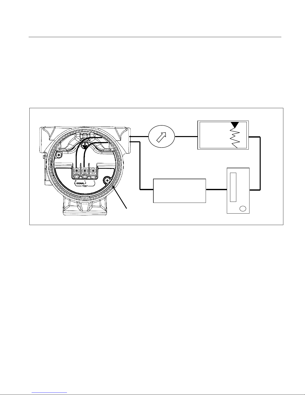
Power
Figure 2-3 – Typical transmitter
Wiring connection
to make electrical connections to the transmitter. Read this section
carefully before proceeding to the electrical installation procedure.
Rosemount 3150 Series transmitters provide a 4-20 mA signal when
connected to a suitable dc power source. Figure 2-3 illustrates a typical
signal loop consisting of a transmitter, power supply, and various
Supply
terminals at 20 mA signal, or the maximum output current required for
proper system operation. Any power supply ripple appears in the
output load. The power supply versus load limitation relationship is
shown in Figure 2-4. See qualification reports for additional details.
The loop load is the sum of the resistance of the signal leads and the
load resistance of the receivers.
2-8
Page 19
Reference Manual
00809-0100-4835 Rev BD
July 2016
Rosemount 3150 Series
POWER SUPPLY (VDC)
2500
1500
2000
500
1000
12
20
25
30
35
40
45
50
48
13.5
15
38
55
IEEE
REGION
DESIGN
REGION
LOAD (OHMS)
53
2150
1725
60
43
0
2150
POWER SUPPLY (VDC)
2500
1500
500
12
1000
20
25
30
35
40
45
50
15
55
KTA
DESIGN
REGION
LOAD (OHMS)
53
60
43
0
1900
2000
Figure 2-4 – Transmitter Supply
Voltage vs. Load
Figure 2-4a – IEEE Qualified and Design Regions
(applicable to 3152N, 3153N and 3154N models only)
QUALIFIED
Figure 2-4b – KTA Qualified and Design Regions
(applicable to 3152K and 3154K models only)
QUALIFIED
REGION
2-9
Page 20

Rosemount 3150 Series
Reference Manual
July 2016
Signal wiring need not be shielded, but twis ted pairs yi eld the best
in the signal
), and
45
43
POWER SUPPLY (VDC)
2500
2000
1500
500
12
1000
20
25
30
35
40
50
15 55
RCC
DESIGN
REGION
LOAD (OHMS)
53
2150
2050
60
0
38
750
Figure 2-4c – RCC-E Qualified and Design Regions
(applicable to 3153K and 3154K models only)
00809-0100-4835 Rev BD
QUALIFIED
REGION
results. Shielded cable should be used for best results in electrically
noisy environments. Do not run signal wiring in conduit or open trays
with AC power wiring, or near heavy electrical equipment. Signal wiring
may be ungrounded (floating) or grounded at any one point
loop.
For installations with EMC performance requirements, consult the
Rosemount Nuclear Instruments, Inc. EMC test reports for additional
details regarding recommended practices for electrical wiring per
various national and international codes and regulations.
The transmitter case may be grounded or ungrounded. Grounding
should be completed in accordance with national and local electrical
codes. Transmitter case can be grounded using either the internal or
external ground connection.
• Internal Ground Connection: The Internal Ground
• External Ground Assembly: The External Ground location is
Connection screw is inside the terminal side of the electronics
housing. The screw is identified by a ground symbol (
is standard on all 3150 Series transmitters.
indicated by the ground symbol ( ) on the module. An
External Ground Assem bl y kit can be ordered as an option on
the 3150 Series transmitter. This kit can also be ordered as a
spare part. Please contact RNII for ordering information.
2-10
Page 21

Reference Manual
00809-0100-4835 Rev BD
July 2016
Rosemount 3150 Series
The capacitance sensing element uses alternating current to generate a
rough the
INSTALLATION
PROCEDURES
Mechanical
Installation consists of mounting the transmitter and conduit and making
WARNING
Improper assembly of mounting bracket to transmitter traditional
process
supplied with the bracket.
.
see
Troubleshooting.
capacitance signal. This alternating current is developed in an oscillator
circuit with a nominal frequency of 110 kHz +/- 11 kHz. This 110 kHz
signal is capacitively-coupled to the transmitter case ground th
sensing element. Because of this coupling, a voltage may be imposed
across the load, depending on choice of grounding.
This impressed voltage, which is seen as high frequency noise, has no
effect on most instruments. Computers with short sampling times in a
circuit where the negative transmitter terminal is grounded detect a
significant noise signal. Filter this signal out by using a large capacitor
(1 uf) or a 110 kHz LC filter across the load. Signal loops at any other
point are negligibly affected by this noise and do not need filtering.
electrical and process connections. The procedures for each operation
follow.
– Transmitter
flange can damage sensor module.
• For safe assembly of bracket to traditional flange, bolts must
break back plane of flange web (i.e. bolt hole), but must not
contact module housing. Use only the RNII approved bolts
1. Attach the mounting bracket to the mounting location as follows:
Panel Mount
Mount the bracket to a panel or other flat surface (for
illustration see Figur e 2-5). Please note that the bolts
required for this step are customer supplied hardware.
Based on qualification tests performed by Rosemount, the
bolts listed in Table 2-1 are recommended for the bracketto-customer interface. Torque each bolt to value shown in
Table 5-2 in Section 5 Maintenance and
Troubleshooting
Pipe Mount
Assemble the bracket kit to a 2-inch pipe (for illustration
Figure 2-5). Torque each bolt to value shown in Table 5-2
in Section 5 Maintenance and Troubleshooting.
2. Attach the transmitter to the mounting bracket (for illustration
see Figure 2-5). Use the four 7/16-20 x ¾ inch bolts with
washers supplied with the transmitter. Torque each bolt to
value shown in Table 5-2 in Section 5 Maintenance and
2-11
Page 22

Rosemount 3150 Series
Reference Manual
00809-0100-4835 Rev BD
July 2016
Table 2-1 – Recommended bolts for
bracket-to-customer interface
(1) The Bracket Code can be found in the 13
(2) Bracket Codes 1 and 5 are available on the 3152 and 3153-series only
(3) Bracket Codes 2 and 7 are available on the 3152, 3153 and 3154-series
(4) Bracket Codes 3 and 8 are available on the 3152, 3153 and 3154-series; this bracket code includes the listed bracket along
with the pipe mount hardware (Rosemount P/N 01154-0044-0001)
BRACKET
CODE
(1)
0
(2)
1
(3)
2
(4)
3
(2)
5
(3)
7
(4)
8
BRACKET TYPE
No Bracket
Supplied
Carbon Steel
Panel Bracket
SST Panel
Bracket
SST 2” Pipe
Mount Bracket
Carbon Steel
Panel Bracket
SST Panel
Bracket
SST 2” Pipe
Mount Bracket
th
position of the 3152, 3153 and 3154 model strings
RECOMMENDED BOLT
FOR BRACKET TO
CUSTOMER INTERFACE
N/A
5/16-18 UNC 2A Grade 2
3/8-24 UNF 2A Grade 2
3/8-24 UNF 2A Grade 2
5/16-18 UNC 2A Grade 2
3/8-24 UNF 2A Grade 2
3/8-24 UNF 2A Grade 2
2-12
Page 23
Reference Manual
00809-0100-4835 Rev BD
July 2016
Rosemount 3150 Series
NOTE: All dimensions are nominal in
inches (millimeters)
Figure 2-5 – Typical Transmitter Mounting Bracket Configuration, Traditional Flange
(1) (2)
(1) Transmitter and bracket orientation with respect to gravity will not impact qualification.
(2) Transmitters can alternatively be mounted inside bracket (as shown below) or with process connection posit i oned adj acent to bracket
(not shown).
(3) A pipe-mount kit with three (3) U-bolts (not shown) is also available. The use of a third U-bolt is necessary to meet KTA seismic
requirements in installations where the KTA Airplane Crash (APC) value of 8g is applicable,. Please consult the applicable RNII Product
Data Sheet (PDS) for ordering information.
2-13
Page 24
Rosemount 3150 Series
Reference Manual
July 2016
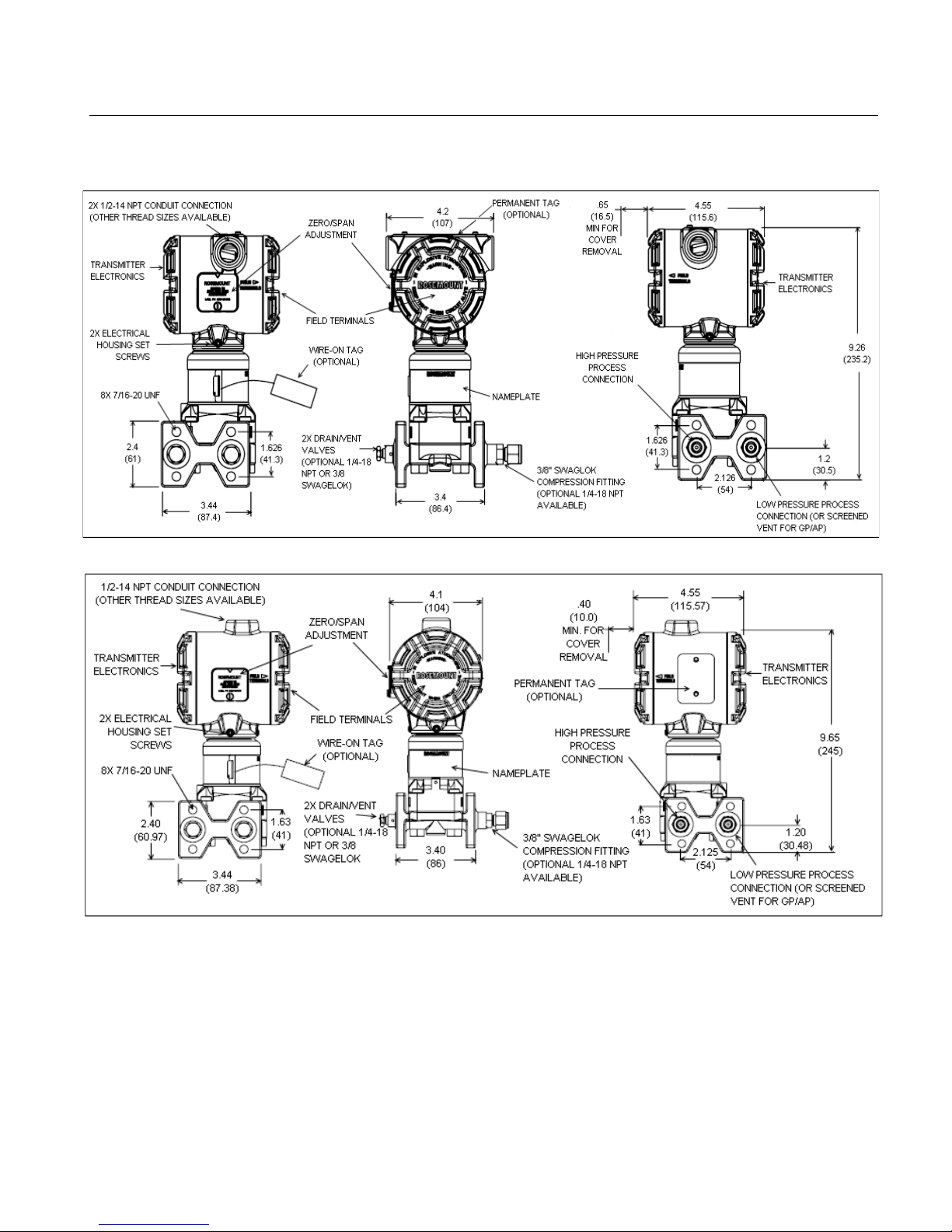
NOTE: All dimensions are nominal in inches (millimeters)
NOTE: All dimensions are nominal in inches (millimeters)
Figure 2-6 – Transmitter Dimensional
Drawings
00809-0100-4835 Rev BD
3152, 3153 Traditional Flange
3154 Traditional Flange
2-14
Page 25

Reference Manual
00809-0100-4835 Rev BD
July 2016
Rosemount 3150 Series
Mechanical – Conduit
Electrical
CAUTION
Be careful not to damage the set screw interface between the sensor
module and the electronics housing.
NOTE
Install the conduit seal in accordance with the manufacturer’s
instructions or use the procedure in this section.
housing conduit hub has two flat surfaces that allow the housing
CAUTION
Do not connect signal leads to the ‘TEST’ terminals.
WARNING
Electrical shock can result in death or serious injury. Avoid contact with
the leads and terminals. High voltage that may be present on leads can
cause electrical shock.
Recheck connections for proper polarity. Position excess wiring
NOTE
Once the cover is installed metal-to-metal, do not torque the cover
further.
1. Seal conduit threads with your plant-approved qualified thread
sealant.
2. Install conduit to the manufacturer’s recommended thread
engagement or torque level. For conduit connectors, refer to
the appropriate manufacturer’s installation manuals. Hold the
electronics housing securely to avoid damaging the set screw
interface between the sensor module and the electronics
housing during conduit installation. The 3154 electronics
to be held securely with open end wrench or other suitable tool
during conduit installation.
3. Provide separate support for the conduit if necessary.
1. Remove the cover from the terminal side of the transmitter.
2. Connect the power leads to the ‘SIGNAL’ terminals on the
transmitter terminal block (see Figure 2-7). Avoid contact with
the leads and terminals. Do not connect the powered signal
wiring to the test terminals, power could damage the test diode.
Torque the terminal screws to the value shown in Table 5-2 in
Section 5 Maintenance and Troubleshooting or hand-tight.
Signal wiring supplies all power to the transmitter. If a 3 wire
connector is utilized or loop groundi ng is requ ired, us e the
ground screw shown in Figure 2-8.
3.
inside the housing so cover installation avoids damage to the
wiring.
4. Carefully replace cover. Caution should be taken that electrical
wires do not interfere with cover installati on so wire da mage
does not occur. Tighten until cover and housing are fully
engaged metal-to-metal (see Figure 2-9). Covers come prelubricated from the factory and should not require additional
lubrication during initial installation.
2-15
Page 26

Rosemount 3150 Series
Reference Manual
00809-0100-4835 Rev BD
July 2016
Figure 2-7 – Terminal Block
Assembly
Figure 2-8 – Ground Screw
Location
Figure 2-9 – Cover and
Housing Metal
Installation
Ground Screw
3152 & 3153
3154
3152 & 3153
3154
Metal-to-Metal Contact
-to-Metal
2-16
Page 27

Reference Manual
00809-0100-4835 Rev BD
July 2016
Rosemount 3150 Series
2-17
Page 28

Rosemount 3150 Series
Reference Manual
July 2016
Overview. . . . . . . . . . . . . . . . . . . . . . . . . . . . . . . . . . . . . .
Calibration Procedures. . . . . . . . . . . . . . . . . . . . . . . . . .
page 3-1
page 3-6
WARNING
consistent with the appropriate qualification parameters.
WARNING
OVERVIEW
This section contains the following transmitter calibration information:
o Linearity
SAFETY MESSAGES
Procedures and instructions in this section may require special
operation preceded by this symbol .
SECTION 3: CALIBRATION
00809-0100-4835 Rev BD
Safety Messages . . . . . . . . . . . . . . . . . . . . . . . . . . . . . . .
Calibration Overview. . . . . . . . . . . . . . . . . . . . . . . . . . . .
• Calibration Overview
o Calibration Considerations
o Definitions
o Span Adjustment Range
o Zero Adjustment Range
• Calibration Procedures
o Span and Zero Adjustment
Calibration Procedure for Zero Based Span (LRV is
Zero DP)
Calibration Procedure for Elevated or Suppressed
Zero
Coarse Zero Select Jumper Position Selection
Procedure
o Damping Adjustment
o Correction for High Static Line Pressure
High Static Pressure Span Effect on Range Codes
1, 2 and 3 DP Transmitters
High Static Pressure Span Correction for Range
Code 4 and 5 DP Transmitters
High Static Line Pressure Zero Correction for DP
Transmitters (All Ranges)
page 3-1
page 3-2
precautions to ensure the safety of the personnel performing the
operation. Refer to the following safety messages before performing an
Explosions can result in death or injury.
• Do not remove the transmitter covers in explosive
environments when the circuit is live.
• Verify that the operating atmosphere of the transmitter is
Electrical shock can result in death or serious injury.
• Avoid contact with the leads and terminals when the circuit is
live.
Page 29

Reference Manual
00809-0100-4835 Rev BD
July 2016
Rosemount 3150 Series
WARNING
transmitter is in service. WARNING
Inc. as spare parts for the 3152, 3153 or 3154.
NOTE
The pressure unit “inches H2O @ 68ºF (20ºC)” is used throughout this
unit will be abbreviated to “inH2O”.
CALIBRATION OVERVIEW
Calibration Considerations
section.
Process leaks could result in death or serious injury.
• Install and tighten all four flange bolts before applying
pressure.
• Do not attempt to loosen or remove flange bolts while the
Replacement equipment or spare parts not approved by Rosemount
Nuclear Instruments, Inc. for use could reduce the pressure retaining
capabilities of the transmitter and may render the instrument
dangerous or adversely impact its qualified status.
• Use only components supplied with the 3152, 3153 or 3154
transmitter or designated by Rosemount Nuclear Instruments,
section. For ease of reading and to conserve space, this pressure
Review this section to become familiar with the fundamentals of
calibrating the Rosemount 3150 Series transmitter. Contact
Rosemount Nuclear Instruments, Inc. with questions regarding
calibrations that are not explained in this manual.
Rosemount 3150 Series transmitters are factory calibrated to the range
shown on the nameplate (see Figure 1-1). This range may be changed
within the limits of the transmitter. Zero may also be adjusted to elevate
(for all models except absolute pressure reference) or suppress (for all
models). Calibrations that hav e a lower rang e va lue b elow zero are
termed zero elevated while calibrations that have a lower range value
above zero are termed zero suppressed.
The zero and span are adjusted during calibration using zero and span
adjustment screws. The adjustment screws are accessible externally
and are located behind the access cover plate on the side of the
electronics housing (see Figure 3-1). Transmitter output increases with
clockwise rotation of the adjustment screws. For normal calibration
adjustments, the zero adjustment screw has negligible effect on the
span and the span adjustment has negligible effect on the zero.
For large amounts of zero adjustment, a course zero selection jumper is
provided. The jumper is located on the electronics assembly,
accessible within the electronics hous in g as shown in F igures 3-1 and
3-2. Models ordered with optional output damping will have a damping
adjustment potentiometer located on the amplifier board (see Figure 3-
2).
Procedures for calibration, including setting the course zero selection
jumper and optional damping adjustment, are provided later in this
3-2
Page 30

Rosemount 3150 Series
Reference Manual
July 2016
Definitions
The following definitions and descriptions are provided to aid in
pressure side of
module by an “L”.
calibration:
DP
Differential pressure between the high pressure “H” and low pressure
“L” process inputs, as marked on the transmitter module.
Upper Range Limit (URL)
The highest pressure the transmitter can be adjusted to measure,
specified in the model ordering information by pressure range code.
Upper Range Value (URV)
The highest pressure the transmitter is adjusted to measure. This
pressure corresponds to 20mA output point.
Lower Range Value (LRV)
The lowest pressure the transmitter is adjusted to measure. This
pressure corresponds to the 4mA output point.
Span = |URV - LRV|
Zero Based Calibration
Calibration where the LRV is zero DP (see Figure 3-3)
Elevated Zero Calibration
Calibration where the LRV is less than zero DP (i.e. the LRV is
achieved when a positive pressure is applied to the low
the DP cell or a vacuum is applied to the high pressure side of the DP
cell – see Figure 3-3).
Suppressed Zero Calibration
Calibration where the LRV is greater than zero DP (i.e. the LRV is
achieved when a positive pressure is applied to the high pressure side
of the DP cell or a vacuum is applied to the low pressure side of the DP
cell – see Figure 3-3).
% Zero Offset
= (LRV/URL) X 100
Note: % Zero Offset is used when making coarse zero adjustments and
replaces the traditional % Zero Elevation and % Zero Suppression
terms. This concept is used due to the limited interaction between zero
and span adjustments on the 3150 series pressure transmitter.
Sign Convention
Positive numbers indicate positive pressure is applied to the high
pressure side of the DP cell or a vacuum is applied to the low pressure
side of the DP cell. The high pressure side is indicated on the sensor
module by an “H”.
Negative numbers indicate positive pressure is applied to the low
pressure side of the DP cell or a vacuum is applied to the high pressure
side of the DP cell. The low pressure side is indicated on the sensor
00809-0100-4835 Rev BD
3-3
Page 31

Reference Manual
00809-0100-4835 Rev BD
July 2016
Rosemount 3150 Series
Damping Adjustment
Coarse Zero
Electronics
housing
Zero and Span
Figure 3-1 – Zero and Span
Figure 3-2 – Electronics Assembly
Assembly located
inside electronics
Select Jumper
Adjustment Screws
(optional)
3-4
Page 32

Rosemount 3150 Series
Reference Manual
00809-0100-4835 Rev BD
July 2016
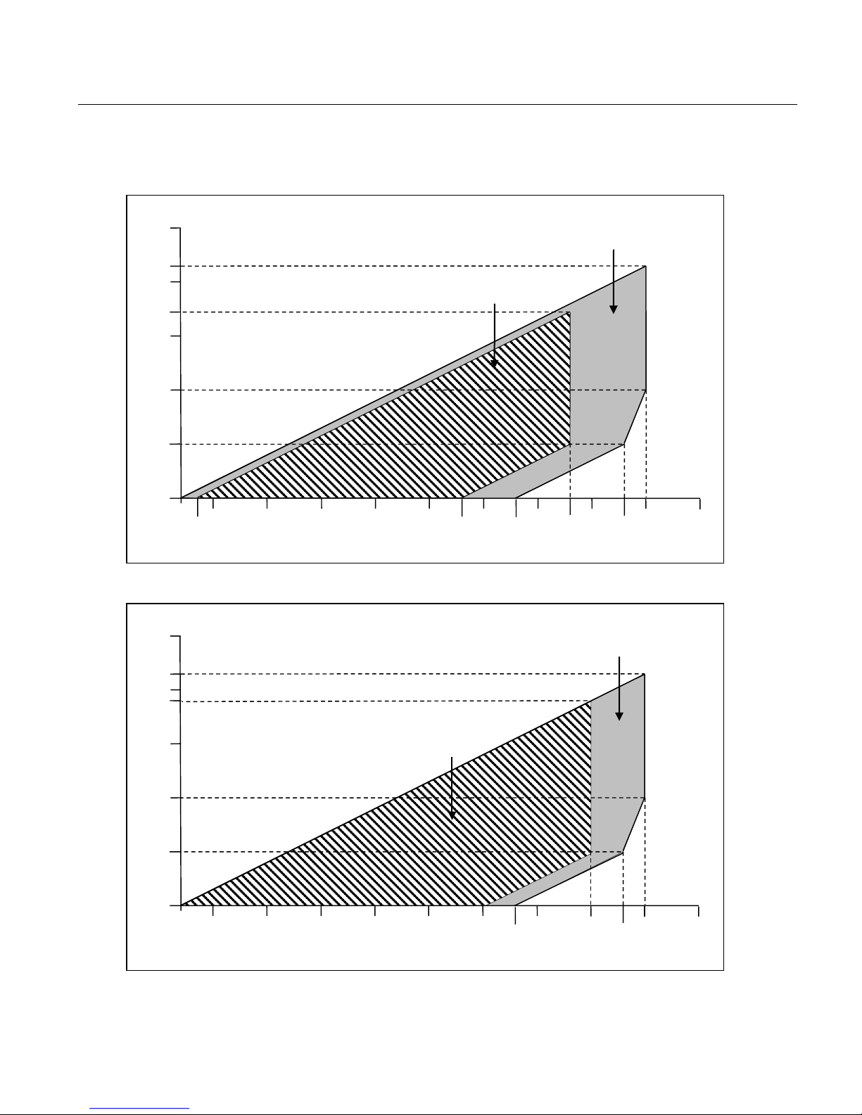
Span Adjustment Range
For transmitter ranges 2 to 6, the span is continuously adjustable to
Zero Adjustment Range
The transmitter zero can be adjusted to achieve a maximum 90%
75 inH2O (-18,6 kPa to 18,6 kPa).
0
4
8
12
16
20
-250
-200
(-49,8)
-100
(
24,9)
-50
(
0
50
(12,4)
100
(24,9)
150
(37,3)
200
(49,8)
250
(62,2)
Differential Pressure Input
(kPa)
Analog Output (mA)
Elevated Zero
Calibration
-250 to -150 inH2O
(
(-100% Zero Offset)
Zero Based
Calibration
0 to 100 inH2O
(0 to 24,9 k Pa)
Suppressed Zero
Calibration
150 to 250 inH2O
(37,3 to 62,2 kPa)
Zero
Adjust
Span Adjust
LRV
URV
URV
LRV
LRV
-150
URV
LRL
URL
(+60% Zero Offset)
allow calibration anywhere between the transmitter URL and 1/10 of
URL. For example, the span on a Range 2 transmitter can be
continuously adjusted bet w een 25 and 250 inH
O (6,22 kPa and 62,2
2
kPa).
For Range 1 transmitters, the span is continuously adjustable to allow
calibration anywhere between the transmitter URL and 1/5 of URL.
For example, the span on a Range 1 transmitter can be continuously
adjusted between 5 and 25 inH
O (1,25 kPa and 6,22 k Pa).
2
Zero Offset for suppressed zero calibrations and -100% Zero Offset
for elevated zero calibrations. To achieve these levels of zero
elevation and zero suppression, the 3150 Series is equipped with a
“Coarse Zero Select Jumper” located on the Electronics Assembly in
the electronics housing (see Figure 3-2).
A graphical representation of three calibrations is shown in Figure 3-
3. Procedures for setting the “Coarse Zero Select Jumper” are
provided in the Calibration Procedure section. The zero may be
elevated or suppressed with the limitation that no applied pressure
within the calibrated range exceeds the URL or LRL. During zero
elevation the transmitter may be calibrated to cross zero, ex. -75 to
Figure 3-3 – Graphical Representation of Elevated Zero, Zero Based, and
Suppressed Zero Calibrations for a Range 2 Transmitter
-62,2 to -37,3 kPa)
(-62,2)
(-37,3)
-
-12,4)
3-5
inH2O
Page 33

Reference Manual
00809-0100-4835 Rev BD
July 2016
Rosemount 3150 Series
CALIBRATION PROCEDURES
The following calibration procedures describe the recommended
Span and Zero Adjustment
CAUTION
The 3150 Series pressure transmitters contain electronic circuit
boards which may be static sensitive.
NOTE
zero and span adjustment screws.
NOTE
pressure unit will be abbreviated to “inH2O”.
Zero Based Calibration Procedure
The adjustment screws are accessible externally and are located
Figure 3-4b uses SI Units (kPa).
steps necessary to calibrate the Rosemount 3150 Series pressure
transmitters.
Electronics housing covers do not need to be removed to access the
The pressure unit “inches H2O @ 68ºF (20ºC)” is used throughout
this section. For ease of reading and to conserve space, this
(LRV is zero DP)
behind the access cover plate on the side of the electronics housing
(see Figure 3-1). The transmitter output increases with clockwise
rotation of the adjustment screw. The Coarse Zero Select jumper is
in the Nominal position for all zero based calibrations.
1. Apply a pressure equivalent to the LRV to the high side
pressure connection and turn Zero adjustment until output
reads 4 mA.
2. Apply a pressure equivalent to the URV to the high side
process connection and turn Span adj us tment until output
reads 20 mA.
3. Check to assure desired outputs are achieved and repeat
steps 1 and 2 if necessary.
Figure 3-4 contains an example of calibrating a transmitter with a zero
based calibration. Figure 3-4a uses English Units (inH
O) while
2
3-6
Page 34

Rosemount 3150 Series
Reference Manual
00809-0100-4835 Rev BD
July 2016
Figure 3-4a – Example for Zero Based
Range 2 for a calibration of 0 to 100 inH2O (100 inH2O span)
and 2 if necessary.
Figure 3-4b – Example for Zero Based
Range 2 for a calibration of 0 to 24,9 kPa (24,9 kPa span)
and 2 if necessary.
Elevated or Suppressed Zero
The easiest way to calibrate a 3150 Series pressure transmitter with
adjustment screw and, if necessary, the Coarse Zero Select Jumper.
NOTE
Jumper Position Selection Procedure.
English units (inH2O) while Figures 3-5b and 3-6b use SI units (kPa)
Calibration (English Units)
Calibration (SI Units)
Calibration Procedure
1. Adjust the zero: With 0 inH2O applied to the transmitter, turn the
Zero adjustment until the transmitter reads 4 mA.
2. Adjust the span: Apply 100 inH
connection. Turn the Span adjustment until the transmitter output
reads 20 mA.
3. Check to assure desired outputs are achieved and repeat steps 1
O to the transmitter high side
2
1. Adjust the zero: With 0 kPa applied to the transmitter, turn the Zero
adjustment until the transmitter reads 4 mA.
2. Adjust the span: Apply 24,9 kPa to the transmitter high side
connection. Turn the Span adjustment until the transmitter output
reads 20 mA.
3. Check to assure desired outputs are achieved and repeat steps 1
an elevated or suppressed zero is to perform a zero-based calibration
and then elevate or suppress the zero by adjusting the zero
For large amounts of elevation or suppression, it may be necessary to
reposition the Coarse Zero Select Jumper. Procedures for repositioning the jumper are described in the Coarse Zero Select
Figures 3-5 and 3-6 contain examples of calibrating a transmitter with
Zero Elevated and Suppressed zeros. Figures 3-5a and 3-6a us e
3-7
Page 35

Reference Manual
00809-0100-4835 Rev BD
July 2016
Rosemount 3150 Series
Figure 3-5a – Example for Elevated
Range 2 with Zero Elevation for a calibration of –120 to –20
transmitter output reads 4mA. Do not use the span adjustment.
NOTE
marked on the transmitter module) will give the same result
4. Apply -20 inH
O to the high side process connection (as marked on
adjustment.
NOTE
on the transmitter module) will give the same result.
Figure 3-5b – Example for Elevated
Range 2 with Zero Elevation for a calibration of –29,9 to –5,0 kPa
transmitter output reads 4mA. Do not use the span adjustment.
NOTE
on the transmitter module) will give the same result.
4.
adjustment.
NOTE
on the transmitter module) will give the same result.
Zero Calibration (English Units)
inH2O (100 inH2O span)
1. Calibrate the transmitter to 0 to 100 inH2O as descri bed in the Zero
Based Calibration Procedure.
2. Consult Table 3-1 to determine appropriate Course Zero Select
Jumper position. If necessary, reposition jumper using the Coarse
Zero Select Jumper Position Selection Procedure.
For this example:
% Zero Offset = (-120 inH
Position the jumper to the MID ZE position.
3. Apply -120 inH
the transmitter sensor module) and adjust the zero until the
Applying 120 inH2O to the low side process connection (as
the transmitter sensor module). Verify the output reads 20mA. If
necessary, adjust the span. Recheck the zero after any span
Applying 20 inH2O to the low side process connection (as marked
O to the high side process connection (as marked on
2
2
O /250 inH2O)*100 = -48%
2
Zero Calibration (SI Units)
(24,9 kPa span)
1. Calibrate the transmitter to 0 to 24,9 kPa as described in the Zero
Based Calibration Procedure.
2. Consult Table 3-1 to determine appropriate Course Zero Select
Jumper position. If necessary, reposition jumper using the Coarse
Zero Select Jumper Position Selection Procedure.
For this example:
% Zero Offset = (-29,9 kPa /62,2 kPa)*100 = -48%
Position the jumper to the MID ZE position.
3. Apply -29,9 kPa to the high side process connection (as marked on
the transmitter sensor module) and adjust the zero until the
Applying 29,9 kPa to the low side process connection (as marked
Apply -5,0 kPa to the high side process connection (as marked on
the transmitter sensor module). Verify the output reads 20 mA. If
necessary, adjust the span. Recheck the zero after any span
Applying 5,0 kPa to the low side process connection (as marked
3-8
Page 36

Rosemount 3150 Series
Reference Manual
00809-0100-4835 Rev BD
July 2016
Figure 3-6a – Example for Suppressed
Range 2 with Zero Suppression for a calibration of 20 to 120
zero after any span adjustment.
Figure 3-6b – Example for Suppressed
Range 2 with Zero Suppression for a calibration of 5,0 to 29,9
zero after any span adjustment.
Zero Calibration (English Units)
Zero Calibration (SI Units)
inH2O (100 inH2O span)
1. Calibrate the transmitter to 0 to 100 inH2O as descri bed in the Zero
Based Calibration Procedure.
2. Consult Table 3-1 to determine appropriate Course Zero Select
Jumper position. If necessary, reposition jumper using the Coarse
Zero Select Jumper Position Selection Procedure.
For this example:
% Zero Offset = (20 inH
Position the jumper to the NOMINAL position.
3. Apply 20 inH
zero until the transmitter output reads 4 mA. Do not use the span
adjustment.
4. Apply 120 inH2O to the high side process connection. Verify the
output reads 20 mA. If necessary, adjust the span. Recheck the
O to the high side process connection, and adjust the
2
O /250 inH2O)*100 = 8%
2
kPa (24,9 kPa span)
1. Calibrate the transmitter to 0 to 24,9 kPa as described in the Zero
Based Calibration Procedure.
2. Consult Table 3-1 to determine appropriate Course Zero Select
Jumper position. If necessary, reposition jumper using the Coarse
Zero Select Jumper Position Selection Procedure.
For this example:
% Zero Offset = (5,0 kPa /62,2 kPa)*100 = 8%
Position the jumper to the NOMINAL position.
3. Apply 5,0 kPa to the high side process connection, and adjust the
zero until the transmitter output reads 4 mA. Do not use the span
adjustment.
4. Apply 29,9 kPa to the high side process connection. Verify the
output reads 20 mA. If necessary, adjust the span. Recheck the
3-9
Page 37

Reference Manual
00809-0100-4835 Rev BD
July 2016
Rosemount 3150 Series
Coarse Zero Select Jumper
The Coarse Zero Select Jumper (see Figure 3-2) is shipped from the
Figure 3-7a – Example for Coarse
Range 2 for a calibration of -175 to -125 inH2O
From Table 3-1, the recommended jumper position is MAX ZE.
Figure 3-7b – Example for Coarse
Range 2 for a calibration of –43,6 to –31,1 kPa
From Table 3-1, the recommended jumper position is MAX ZE.
NOTE
reinstall the cover.
Table 3-1 – Coarse Zero Select
(1)
% Zero Offset
Range 1
% Zero Offset
Ranges 2-6
Recommended
Jumper Position
-
60% to 90%
MAX ZS
30% to 90%
20% to 60%
MID ZS
-30% to 30 %
-20% to 20 %
Nominal
-100% to -30%
-60% to -20%
MID ZE
-
-100% to -60%
MAX ZE
desired calibration.
Position Selection Procedure
factory in either the Nominal position or the position required to obtain
the calibration specified when ordered. Changes to the factory
calibration may require repositioning of the jumper. To do this, follow
the procedure below:
1. Calculate the % zero offset using the following formula:
% Zero Offset = (LRV/URV) X 100
Where:
LRV = Lower Range Value of desired calibration
URL = Transmitter Upper Range Limit
2. Consult Table 3-1 to determine recommended jumper
position.
3. If the jumper requires re-positioning, remove the electronics
housing cover opposite the “Field Terminals” label. Remove
the jumper by squeezing the sides and pulling out.
Reposition the jumper with the arrow pointing to the
recommended position and carefully push in. Ensure both
jumper clips are fully engaged and return to calibration
If no change is required, return to calibration procedure.
procedure.
Figure 3-7 contains an example of determining the recommended
position of the Coarse Zero Select Jumper. Figure 3-7a uses English
Units (inH
O) while 3-7b uses SI Units (kPa).
2
Zero Adjustment (English Units)
Zero Adjustment (SI Units)
LRV = -175 inH
% Zero Offset = (-175 inH
LRV = -43,6 kPa
% Zero Offset = (-43,6 kPa /62,2 kPa)*100 = -70%
If you remove either cover during the above procedures, follow the
instructions in Section 5 Maintenance and Troubleshooting to
(1) % Zero Offset values and jumper positions indicated are
approximations. Select jumper position as needed to achieve the
O
2
O /250 inH2O)*100 = -70%
2
3-10
Page 38

Rosemount 3150 Series
Reference Manual
00809-0100-4835 Rev BD
July 2016
Damping Adjustment
The 3150 Series amplifier boards for transmitter output code options
CAUTION
permanent damage and require electronics assembly replacement.
NOTE
If you remove either electronics housing cover during the above
Troubleshooting to reinstall the cover.
B (3152) and T (3153 and 3154) are designed to permit damping of
rapid pulsations in the pressure source through adjustment of the
single turn damping adjustment potentiometer (see Figure 3-2).
When adjusted to the maximum position (clockwise stop), timeconstant values of at least 1.20 seconds are available for 3152, 3153,
and 3154 transmitters. Transmitters with the electronics damping
option are calibrated and shipped with the adjustment set at the
counterclockwise stop, giving the minimum time constant.
Damping adjustment should be made with the transmitter calibrated
to the intended application calibration. To adjust the damping, turn
the damping adjustment potentiometer until the desired time constant
is obtained. It is best to set the damping to the shortest possible time
constant. Since transmitter calibration is not affected by the damping
setting, damping may be adjusted with the transmitter installed on the
process.
The damping adjustment potentiometer has positive stops at both
ends. Forcing the potentiometer beyond the stops may cause
procedures, follow the instruc tions in Section 5 Maintenance and
3-11
Page 39

Reference Manual
00809-0100-4835 Rev BD
July 2016
Rosemount 3150 Series
Correction for High Static
High Static Line Pressure Span
Rosemount 3150 Series Range 1, 2, and 3 differential pressure
High Static Line Pressure Span
Rosemount 3150 series Range 4 and 5 pressure transmitters
Table 3-2 – Range 4 and 5 Correc tion
Range 4 and 5 Span Correction Factor
% Input Reading per 1000 psi (6,90 MPa)
Range 4
1.00%
(1)
Range 5
1.25%
(1)
NOTE
procedure described in Method 2 (see pg. 3-14) is recommended.
Line Pressure
Effect on Range Codes 1, 2 and 3
DP Transmitters
Correction for Range Code 4 and 5
DP Transmitters
Factors
transmitters do not require correction for high static pressure span
effect. The correction for these ranges occurs within the sensor.
experience a systematic span shift when operated at high static line
pressure. It is linear and correctable during calibration.
The correction factor for span shift caused by the application of static
line pressure is shown in Table 3-2
(1) Correction factors have an uncertainty of ±0.20% of
input reading per 1000 psi (6,90 MPa)
The following illustrates two methods of correcting for the high static
pressure span shift. Examples follow each method.
Method 1 for High Static Line Pressure, Ranges 4 and 5
Adjust transmitter output while leaving the input pressure at desired in
service differential pressures. Use on of the following formula sets
(depending on the pressure units being used to calibrate):
If using English Units (psi):
Corrected output reading (at LRV) =
4 mA + ((S X P/1000 X LRV)/Span) X 16 mA
Corrected output reading (at URV) =
20 mA + ((S X P/1000 X URV)/Span) X 16 mA
If using SI Units (MPa):
Corrected output reading (at LRV) =
4 mA + ((S X P/6,90 X LRV)/Span) X 16 mA
Corrected output reading (at URV) =
20 mA + ((S X P/6,90 X URV)/Span) X 16 mA
Where:
S = Value from Table 3-2 divided by 100
LRV = Lower Range Value
URV = Upper Range Value
P = Static Line Pressure
Span = Calibrated Span
For corrections where the calculated output adjustment exceeds the
output high or low adjustment limits, the pressure input adjust
3-12
Page 40

Rosemount 3150 Series
Reference Manual
00809-0100-4835 Rev BD
July 2016
Figure 3-8 outlines examples of calculating a High Static Line
Figure 3-8a – Example for High Static
Range 4; for a calibration of –10 to 45 psi corrected for 1,500 psi static
psi.
Figure 3-8b – Example for High Static
Range 4; for a calibration of –0,07 to 0,31 MPa corrected for 10,34 MPa
0,31 MPa.
Pressure Span Correction using Method 1. Figure 3-8a uses English
units (psi) while Figure 3-8b uses SI units (MPa).
Line Pressure, Span Correction using
Method 1 (English Units)
line pressure:
1. Calculate the corrected output reading (at LRV)
= 4 mA + ((0.01 X 1500 psi/1000 psi X (-10 psi))/55 psi) X 16 mA
= 3.956 mA
2. Calculate the corrected output reading (at URV)
= 20 mA + ((0.01 X 1500 pis/1000 psi X 45 psi)/55 psi) X 16 mA
= 20.196 mA
3. At atmospheric static line pressure, apply 10 psi to the low side
process connection (-10 psi), and adjust the zero until the
transmitter output reads 3.956 mA.
4. Remaining at atmospheric static line pressure, apply 45 psi to the
high side process co nnection and adjust the span until the
transmitter output reads 20.196 mA.
5. Check to assure desired outputs are achieved and repeat steps 3
and 4 if necessary.
When the transmitter is exposed to 1,500 psi static line pressure, within
specified uncertainties, the output will be 4 mA at -10 psi and 20 mA at 45
Line Pressure, Span Correction using
Method 1 (SI Units)
static line pressure:
1. Calculate the corrected output reading (at LRV)
= 4 mA + ((0,01 X 10,34 MPa/6,90 MPa X (-0,07 MPa))/0,38 MPa) X 16 mA
= 3,956 mA
2. Calculate the corrected output reading (at URV)
= 20 mA + ((0,01 X 10,34 MPa/6,90 MPa X 0,31 MPa)/0,38 MPa) X 16 mA
= 20,196 mA
3. At atmospheric static line pressure, apply 0,07 MPa to the low side
process connection (-0,07MPa), and adjust the zero until the
transmitter output reads 3,956 mA.
4. Remaining at atmospheric static line pressure, apply 0,31 MPa to
the high side process connection and adjust the span until the
transmitter output reads 20,196 mA.
5. Check to assure desired outputs are achieved and repeat steps 3
and 4 if necessary.
When the transmitter is exposed to 10,34 MPa static line pressure, within
specified uncertainties, the output will be 4 mA at -0,07 MPa and 20 mA at
3-13
Page 41

Reference Manual
00809-0100-4835 Rev BD
July 2016
Rosemount 3150 Series
High Static Line Pressure Span
Method 2 for High Static Line Pressure, Ranges 4 and 5
units (psi) while Figure 3-10b uses SI units (MPa).
Correction for Range Code 4 and 5
DP Transmitters (continued)
Adjust transmitter pressure input while leaving the output at 4 mA and
20 mA. Use one of the following formula sets (depending on the
pressure units being used to calibrate):
If using English Units (psi):
Corrected LRV pressure input =
Corrected URV pressure input =
If using SI Units (MPa):
Corrected LRV pressure input =
Corrected URV pressure input =
Where:
Figures 3-9 and 3-10 outline two examples of calculating a High
Static Line Pressure Span Correction using Method 2.
“Example 1” in Figure 3-9 contains a calculation for a Zero Based
Calibration Range. Figure 3-9a uses English units (psi) for the
calculation while Figure 3-9b uses SI units (MPa)
“Example 2” in Figure 3-10 demonstrates the calculation for a Zero
Elevated Calibration Range. “Example 2” can also be followed for
Zero Suppressed Calibration Ranges. Figure 3-10a uses English
Desired LRV – ((S X LRV) X (P/1000))
Desired URV – ((S X URV) X (P/1000))
Desired LRV – ((S X LRV) X (P/6,90))
Desired URV – ((S X URV) X (P/6,90))
S = Value from Table 3-2 divided by 100
LRV = Lower Range Value
URV = Upper Range Value
P = Static Line Pressure
Span = Calibrated Span
3-14
Page 42

Rosemount 3150 Series
Reference Manual
00809-0100-4835 Rev BD
July 2016
Figure 3-9a – Example 1 for High
Range 4 for a calibration of 0 to 45 psi corrected for 1,500 psi static line
specified uncertainties, the output will be 4 mA at 0 psi and 20 mA at 45 psi.
Figure 3-9b – Example 1 for High
Range 4 for a calibration of 0 to 0,31 MPa corrected for 10,34
MPa.
Static Line Pressure, Span Corr ection
using Method 2 (English Units)
Static Line Pressure, Span Corr ection
using Method 2 (SI Units)
pressure
1. In this example LRV is 0 psid. Zero differential pressure points
require no span correction.
2. Calculate the corrected URV pressure input
= 45 psi – ((0.01 X 45 psi) X (1500 psi/1000 psi))
= 44.325 psi
3. At atmospheric static line pressure, with zero differential pressure
applied, adjust the zero until the transmitter output reads 4 mA.
4. Remaining at atmospheric static line pressure, apply 44.325 psi to
the high side process connection and adjust the span until the
transmitter output reads 20 mA.
5. Check to assure desired outputs are achieved and repeat steps 3
and 4 if necessary.
When the transmitter is exposed to 1,500 psi stat ic line pres sure, withi n
MPa static line pressure
1. In this example LRV is 0 MPa. Zero differential pressure points
require no span correction.
2. Calculate the corrected URV pressure input
= 0,31 MPa – ((0,01 X 0,31 MPa) X (10,34 MPa/6,90 MPa))
= 0,305 MPa
3. At atmospheric static line pressure, with zero differential pressure
applied, adjust the zero until the transmitter output reads 4 mA.
4. Remaining at atmospheric static line pressure, apply 0,305 MPa to
the high side process connection and adjust the span until the
transmitter output reads 20 mA.
5. Check to assure desired outputs are achieved and repeat steps 3
and 4 if necessary.
When the transmitter is exposed to 10,34 MPa static line pressure, within
specified uncertainties, the output will be 4 mA at 0 MPa and 20 mA at 0,305
3-15
Page 43

Reference Manual
00809-0100-4835 Rev BD
July 2016
Rosemount 3150 Series
Figure 3-10a – Example 2 for High
Range 5 for a calibration of –250 to 750 psi corrected for 1,500 psi static
psi.
Figure 3-10b – Example 2 for High
Range 5 for a calibration of –1,72 to 5,17 MPa corrected for 10,34 MPa
5,17 MPa.
Static Line Pressure, Span Corr ection
using Method 2 (English Units)
Static Line Pressure, Span Corr ection
using Method 2 (SI Units)
line pressure
1. Calculate the corrected LRV pressure input
= -250 psi – ((0.0125 X -250 psi) X (1500 psi/1000 psi))
= -245.31 psi
2. Calculate the corrected URV pressure input
= 750 psi – ((0.0125 X 750 psi) X (1500 psi/1000 psi))
= 735.94 psi
3. At atmospheric static line pressure, apply 245.31 psi to the low side
process connection (-245.31 psi) and adjust the zero until the
transmitter output reads 4 mA.
4. Remaining at atmospheric static line pressure, apply 735.94 psi to
the high side process connection and adjust the span until the
transmitter output reads 20 mA.
5. Check to assure desired outputs are achieved and repeat steps 3
and 4 if necessary.
When the transmitter is exposed to 1,500 psi static line pressure, within
specified uncertainties, the output will be 4 mA at -250 psi and 20 mA at 750
static line pressure
1. Calculate the corrected LRV pressure input
= -1,72 MPa – ((0,0125 X -1,72 MPa) X (10,34 MPa/6,90 MPa))
= -1,69 MPa
2. Calculate the corrected URV pressure input
= 5,17 MPa – ((0,0125 X 5,17 MPa) X (10,34 MPa/6,90 MPa))
= 5,07 MPa
3. At atmospheric static line pressure, apply 1,69 MPa to the low side
process connection (-1,69 MPa) and adjust the zero until the
transmitter output reads 4 mA.
4. Remaining at atmospheric static line pressure, apply 5,07 MPa to
the high side process connection and adjust the span until the
transmitter output reads 20 mA.
5. Check to assure desired outputs are achieved and repeat steps 3
and 4 if necessary.
When the transmitter is exposed to 10,34 MPa static line pressure, within
specified uncertainties, the output will be 4 mA at -1,72 MPa and 20 mA at
3-16
Page 44

Rosemount 3150 Series
Reference Manual
00809-0100-4835 Rev BD
July 2016
High Static Line Pressure Zero
Zero shift with static pressure is not systematic. However, the effect
Line Pressure for a transmitter with a non-zero based c alibr ati on.
Figure 3-11 – High Static Line
If -0.007 mA was calculated in step f and the LRV reads 4.002 mA,
4.002 mA.
Linearity
Linearity is factory optimized and requires no field adjustment.
Correction for Differential Pressure
Transmitters (All Ranges)
can be eliminated during calibration. To trim out the zero error at high
static line pressure, perform the following:
1. If the calibrated range contains zero differential pressure:
a. Calibrate the pressure transmitter according to the
b. Apply atmospheric line pressure with zero differential
c. Record the output reading.
d. Apply the intended line pressure at zero differential
e. Adjust the zero to match the reading obtained in step c.
2. If the calibrated range does not contain zero differentia l
pressure:
a. Calibrate the pressure transmitter to the intended span
b. Apply atmospheric line pressure with zero differential
c. Record the output reading.
d. Apply the intended line pressure at zero differential
e. Record the output reading.
f. Subtract the reading in step e from the reading in step
g. Calibrate the transmitter to the zero elevated or zero
h. For range code 4 and 5 only, correct for static pressure
i. At the LRV, with atmospheric line pressure applied,
Figure 3-11 outlines an example of a Zero Correction for High Static
preceding sections.
pressure.
pressure.
using the Zero Based Calibration Procedure.
pressure.
pressure.
c. Note the sign associated with the calculated value,
as the sign is maintained for the adjustment in step i.
suppressed calibration using the Elevated or
Suppressed Zero Calibration Procedure.
span effect as described in Static Pressu re Span
Correction for Range Code 4 and 5 DP Transmitters
adjust the zero by the amount calculated in step f.
Pressure, Zero Correction Example
3-17
adjust the zero until the LRV reads 3.995 mA. DO NOT ADJUST
THE SPAN. When static pressure is applied, the output should read
Page 45

Reference Manual
00809-0100-4835 Rev BD
July 2016
Rosemount 3150 Series
3-18
Page 46

Rosemount 3150 Series
Reference Manual
4835 Rev BD
July 2016
Overview. . . . . . . . . . . . . . . . . . . . . . . . . . . . . . . . . . . . . .
Reverse Polarity Protection . . . . . . . . . . . . . . . . . . . . . .
page 4-1
page 4-5
OVERVIEW
This section provides a brief description of basic 3150 series pressure
• Reverse Polarity Protection
SECTION 4: OPERATION
00809-0100-
Transmitter Theory of Operation . . . . . . . . . . . . . . . . . .
The Sensor Cell . . . . . . . . . . . . . . . . . . . . . . . . . . . . . . . .
Demodulator. . . . . . . . . . . . . . . . . . . . . . . . . . . . . . . . . . .
Oscillator . . . . . . . . . . . . . . . . . . . . . . . . . . . . . . . . . . . . .
Voltage Regulator . . . . . . . . . . . . . . . . . . . . . . . . . . . . . .
Current Control . . . . . . . . . . . . . . . . . . . . . . . . . . . . . . . .
Current Limit . . . . . . . . . . . . . . . . . . . . . . . . . . . . . . . . . .
page 4-2
page 4-3
page 4-4
page 4-5
page 4-5
page 4-5
page 4-5
transmitter operations in the following order:
• Transmitter Theory of Operation
• The Sensor Cell
• Demodulator
• Oscillator
• Voltage Regulator
• Current Control
• Current Limit
Page 47

Reference Manual
00809-0100-4835 Rev BD
July 2016
Rosemount 3150 Series
TRANSMITTER THEORY OF
The block diagram in Figure 4-1 illustrates the operation of the 3150
+
−
=
21
12
1
CC
CC
kP
2
1
CC
I
fV
ref
p
p
+
=
−
( )
1
2
CCfVI
ppdiff
−=
−
12
12
CCCC+
−
OPERATION
series pressure transmitter.
The 3150 series pressure transmitters have a variable capacitance
sensor (see Figure 4-2). Differential capacitance between the sensing
diaphragm and the capacitor plates is converted electronically to a 2
wire, 4-20mA dc signal based on the following formulas:
P is the process pressure.
k
Where:
is a constant.
1
is the capacitance between the high-pressure
C
1
side and the sensing diaphragm.
C
Where:
I
ref
V
p-p
f is the oscillation frequency.
Where:
I
diff
Therefore:
is the capacitance between the low-pressure
2
side and the sensing diaphragm
is the reference current.
is the peak to peak oscillation voltage.
is the difference in current between C1 and C2.
P = constant x I
diff
= I
ref
4-2
Page 48

Rosemount 3150 Series
Reference Manual
4835 Rev BD
July 2016
THE SENSOR CELL
Process pressure is transmitted through an isolating diaphragm and
and 20 V
p-p
.
Figure 4-1 Block Diagram
00809-0100-
silicon oil fill fluid to a sensing diaphragm in the center of the Sensor.
Figure 4-2 – The Sensor Cell
4-3
The reference pressure is transmitted in a like manner to the other side
of the sensing diaphragm. The capacitance plates on both sides of the
sensing diaphragm detect the position of the sensing diaphragm. The
capacitance between the sensing diaphragm and either capacitor plate
ranges from 40pf to 80pf depending on input pressure. An oscillator
drives the sensor through the transformer windings at roughly 110 kHz
Page 49

Reference Manual
00809-0100-4835 Rev BD
July 2016
Rosemount 3150 Series
DEMODULATOR
The demodulator consists of a diode bridge that rectifies the ac signal
from the sensor cell to a dc signal. The oscillator driving current, I
sum of the dc currents through two transformer windings), is kept a
constant by an integrated circuit oper at
output of the demodulator is a current directly proportional to pressure,
i.e.
( )
1
2
CCfV
I
pp
diff
−=
−
The diode bridge and temperature compensation circuits are located
inside the sensor module.
Capacitor Plates
Silicon Oil
Isolating Diaphragms
Center Diaphragm
Rigid
Insulation
(the
ref
,
ional amplifier (op amp). The
4-4
Page 50

Rosemount 3150 Series
Reference Manual
00809-0100-
4835 Rev BD
July 2016
OSCILLATOR
The oscillator frequency is determined by the capacitance of the
variable about a nominal value of 110k H z. An operational amplifier acts
21
CC
I
fV
ref
pp
+
=
−
sensing element and the inductance of the transformer windings. The
sensing element capacitance is variable. Therefore, the frequency is
VOLTAGE REGULATOR
CURRENT CONTROL
CURRENT LIMIT
REVERSE POLARITY
as a feedback control circuit and controls the oscillator drive voltage
such that:
The transmitter uses a zener diode, transis tors , as s ociated res is tor s
and capacitors to provide a constant reference voltage of 3.2 Vdc and a
regulated voltage of 7.4 Vdc for the oscillator and amplifiers
The current control amplifier consists of two operational amplifiers, two
transistors, and associated components. The first amplifier provides an
adjustable gain output proportional to the sum of the differential sensor
current and a zero adjustment current. This output is supplied to the
second amplifier, which controls the current in the 4-20mA loop
proportionally.
The current limiter prevents output current from exceeding 30mA
nominal in an overpressure condition. Conversely, minimum output is
limited to 3 mA nominal. Both the minimum and maximum current limits
may vary slightly depending upon sensor pressure range code and
associated calibration.
A diode provides reverse polarity protection.
PROTECTION
.
4-5
Page 51

Reference Manual
00809-0100-4835 Rev BD
July 2016
Rosemount 3150 Series
4-6
Page 52

Rosemount 3150 Series
Reference Manual
00809-0100-4835 Rev BD
July 2016
Overview . . . . . . . . . . . . . . . . . . . . . . . . . . . . . . . . . . . . .
Post Assembly Tests . . . . . . . . . . . . . . . . . . . . . . . . . . .
page 5-1
page 5-16
WARNING
consistent with the appropriate qualification parameters.
OVERVIEW
This section outlines techniques for checking out the components, a
• Post Assembly Tests
SAFETY MESSAGES
Procedures and instructions in this section may require special
an operation preceded by this symbol .
SECTION 5: MAINTENANCE & TROUBLESHOOTING
Safety Messages. . . . . . . . . . . . . . . . . . . . . . . . . . . . . . .
General Considerations. . . . . . . . . . . . . . . . . . . . . . . . .
Test Terminal. . . . . . . . . . . . . . . . . . . . . . . . . . . . . . . . . .
Electronics Assembly Checkout . . . . . . . . . . . . . . . . . .
Sensor Module Checkout. . . . . . . . . . . . . . . . . . . . . . . .
Disassembly Procedure . . . . . . . . . . . . . . . . . . . . . . . . .
Reassembly Procedure. . . . . . . . . . . . . . . . . . . . . . . . . .
page 5-1
page 5-3
page 5-5
page 5-5
page 5-6
page 5-7
page 5-11
method for disassembly and reassembly, and a troubleshooting guide.
• General Considerations
• Test Terminal
• Electronics Assembly Checkout
• Sensor Module Checkout
• Disassembly Procedure
o Process Flange Removal
o Electrical Housing Disassembly
• Reassembly Procedure
o Electrical Housing Reassembly
o Process Flange Reassembly
precautions to ensure the safety of the personnel performing the
operation(s). Refer to the following safety messages before performing
Explosions can result in death or injury.
• Do not remove the transmitter covers in explosive
environments when the circuit is live.
• Verify that the operating atmosphere of the transmitter is
Page 53

Reference Manual
00809-0100-4835 Rev BD
Rosemount 3150 Series
WARNING
live.
WARNING
NOTE
Maintenance of traceability of any replacement parts is the
manual preceding Section 1).
WARNING
WARNING
July 2016
Electrical shock can result in death or serious injury.
• Avoid contact with the leads and terminals when the circuit is
Process leaks could result in death or serious injury.
• Install and tighten all four flange bolts before applying
pressure.
• Do not attempt to loosen or remove flange bolts while the
transmitter is in service.
Residual process fluid may remain after disassembly of process
flanges. If this fluid is potentially contaminated, take appropriate safety
measures.
Replacement equipment or spare parts not approved by Rosemount
Nuclear Instruments, Inc. for use could reduce the pressure retaining
capabilities of the transmitter and may render the instrument
dangerous or adversely impact its qualified status.
• Use only components supplied with the 3152, 3153 or 3154
transmitter or designated by Rosemount Nuclear Instruments,
Inc. as spare parts for the 3152, 3153 or 3154.
responsibility of the user (see Important Notice at the beginning of this
5-2
Page 54

Rosemount 3150 Series
Reference Manual
00809-0100-
4835 Rev BD
July 2016
GENERAL CONSIDERATIONS
The Rosemount 3150 Series transmitters have no moving parts and
numbers in the exploded view.
require a minimum of scheduled maintenance. Calibration procedures
for range adjustments are outlined in Section 3 Calibration. A
calibration check should be conducted after inadvertent exposure to
overpressure, unless your plant considers this factor separately in the
plant error analysis.
Test terminals are available for in-process checks. For further checks,
the transmitter can be divided into two active physical components: the
sensor module and the electronics assembly.
An exploded view drawing of the transmitter is provided in Figure 5-1.
In the following procedures, numbers in parentheses refer to item
5-3
Page 55

Reference Manual
00809-0100-4835 Rev BD
Rosemount 3150 Series
1
Electronics Cover
8
Sensor Module
2
O-ring for Electronics Cover
9
C-rings for Process Flange
3
Coarse Zero Select Jumper
10
Process Flange
4
Electronics Assembly
11
Bolts for Process Flange
Electronics Housing Assembly
(includes set screws)
6
Terminal Block Assembly
13
Flange Cap Screws
7
O-ring for Header
July 2016
Figure 5-1 – Parts Drawing, Exploded View
Table 5-1 – 3150 Series Parts List
ITEM # DESCRIPTION ITEM # DESCRIPTION
5
12 Housing Set Screws
5-4
Page 56

Rosemount 3150 Series
Reference Manual
4835 Rev BD
July 2016
TEST TERMINAL
The test terminals are connected across a diode through which the
connection or meter should not exceed 10 ohms.
ELECTRONICS ASSEMBLY
NOTE
Numbers in parentheses refer to item numbers in Figure 5-1.
NOTE
handled and/or uncovered.
The electronics assembly (4) is not field-repairable and must be
this manual.
CHECKOUT
00809-0100-
loop signal current passes. The indicating meter or test equipment
shunts the diode when connected to the test terminals. As long as
the voltage across the terminals is kept below the diode threshold
voltage, no current passes through the diode. To ensure that there is
no current leaking through the diode while making a test reading or
when connecting an indicating meter, the resistance of the test
3150 Series transmitters contain electronic circuit boards which may
be static sensitive. Therefore, observe proper ESD
precautions/techniques whenever the electronics assemblies are
replaced if defective.
To check the electronics assembly for a malfunction, substitute a
spare assembly into the transmitter using the procedures in this
section.
To remove the existing electronics assembly, refer to the steps
outlined in the Electrical Housing Disassembly section.
To install the new electronics assembly, refer to the steps outlined in
Electrical Housing Reassembly section.
If this procedure reveals a malfunctioning assembly, return the
defective assembly to Rosemount Nuclear Instruments, Inc. for
replacement. See Notices regarding field repair at the beginning of
5-5
Page 57

Reference Manual
00809-0100-4835 Rev BD
Rosemount 3150 Series
SENSOR MODULE
CHECKOUT
NOTE
Numbers in parentheses refer to item numbers in Figure 5-1.
The sensor module (8) is not field-repairable and must be replaced if
section. This will
pins (the positive (+) lead should be connected to
NOTE
Results obtained using the above proc edure m ay vary depending on the
regarding test procedure and/or results.
NOTE
The above procedure does not completely test the sensor module. If
module.
July 2016
defective. If no visible defect such as a punctured isolating diaphragm or
loss of fill fluid is observed, check the sensing module in the following
manner:
1. Remove the electronics assembly (4) from the transmitter per the
steps outlined in Electrical Housing Disassembly
allow access to the sensor module pins located at the top of the
sensor module.
Refer to Figure 5-2 for the following steps.
DIODE CHECK
Using a digital multimeter with diode test functionality, measure
the voltage drop of the sensor diodes between the following
sensor module
the first sensor module pin listed):
A. Pin #3 and Pin #5
(Should measure approximately 1.2 volts)
B. Pin #4 and Pin #3
(Should measure approximately 1.2 volts)
C. Pin #4 and Pin #5
(Should measure approximately 2.4 volts)
specific meter that is used for testing (manufacturer, model, type, etc.).
Please contact Rosemount Nuclear Instruments, Inc. with any questions
RESISTANCE CHECK
Using a low-voltage ohmmeter, check resistance between the
electronics assembly replacement does not correct the abnormal
condition and no other problems are obvious, replace the sensor
following sensor module pins:
A. Pin #1 and all other Pi ns
(All measurements should be >10 mega ohms)
B. Pin #2 and Pin #5
(Should measure between 15 kilo ohms and 38 kilo
ohms)
C. All Pins and the module housing
(All measurements between pins and module housing
should be >10 mega ohms)
5-6
Page 58

Rosemount 3150 Series
Reference Manual
4835 Rev BD
July 2016
DISSASSEMBLY
NOTE
• Remove all electrical leads and conduit.
WARNING
Residual process fluid may remain after disassembly of process
safety measures.
NOTE
Numbers in parentheses refer to item numbers in Figure 5-1.
NOTE
handled and/or uncovered.
NOTE
5-14) before attempting disassembly.
Process Flange Removal
1. Remove the transmitter from service before disassembling
flange and sensor module.
2
1 3 4
5
MODULE HOUSING
Figure 5-2 – Sensor Module Pin
Connections
00809-0100-
PROCEDURE
Before removing the transmitter from service:
• Follow all plant safety rules and procedures.
• Isolate and vent the process from the transmitter before
removing the transmitter from service.
flanges. If this fluid is potentially contaminated, take appropriate
3150 Series transmitters contain electronic circuit boards which may
be static sensitive. Therefore, observe proper ESD
precautions/techniques whenever the electronics assemblies are
Special testing and part replacement are required for reassembly.
Read the Process Flange Reassembly Procedure section (see pg.
flanges.
2. Remove the two flange cap screws (13).
3. Detach process flange (10) by removing the four large bolts (11).
Take care not to scratch or puncture the isolating
diaphragms. Identify the orientation of flange with respect to
sensor module for reassembly.
4. Carefully remove the C-rings (9). Do not reuse C-rings. Take
5-7
care not to scratch the sealing surfaces on the process
Page 59

Reference Manual
00809-0100-4835 Rev BD
Rosemount 3150 Series
Electrical Housing
WARNING
Remove power from the transmitter before removing either the
terminal side or circuit side cover (1).
Electronics Assembly Re mo v al
1. The electronics assembly (4) is accessible by unscrewing the
Terminal Block Removal
1. The signal terminals and test terminals are accessible by
IMPORTANT
The Electronics Housing (5), Housing Set Screws (12) and
Rosemount Nuclear Instruments, Inc.
July 2016
Disassembly
cover (1) on the electronics side. This compartment is not
specifically identified by notes on the housing (5), but is located
opposite of the side marked “FIELD TERMINALS.”
2. Before removing the electronics assembly, align the zero and
span adjustment screws so that their slots are perpendicular to
the board, as shown in Figure 5-3.
3. Unscrew the two 6-32 captive screws holding the electronics
assembly to the housing and pull the electronics assembly from
the housing (see Figure 5-3).
4. Unclip and disconnect the connector plug from the top of the
sensor module (8) to completely remove the electronics assembly
(see Figure 5-4). To remove connector plug, apply even pressure
to both clips and pull the connector body up from the sensor
module. Do not pull on the cable wires.
unscrewing the cover (1) on the terminal side. This compartment
is identified by the “FIELD TERMINALS” notes on the sides of the
electronics housing (5).
2. The terminal block assembly (6) is removed by removing the two
6-32 screws and pulling the terminal block assembly out of the
housing (see Figure 5-5).
Sensor Module (8) Assembly cannot be disassembled in the
field. The Housing Set Screws (12) are held in place by a thread lock
compound (Loctite
If this interface is damaged, the qualification of the transmitter
becomes invalid. For any maintenance that requires the sensor
module (8) be removed from the housing (5), please contact
®
266) applied at the factory during manufacturing.
5-8
Page 60

Rosemount 3150 Series
Reference Manual
4835 Rev BD
July 2016
Connector Plug
Squeeze the two clips and pull
up on the connector plug
Two 6-32 Screws
Ensure potentiometer s
Figure 5-3 – Location of Zero and Span
Adjustment Screws and Electronics
Assembly Captive Scre ws
00809-0100-
and adjustment screws
are aligned while
removing electronics
Figure 5-4 – Removing Electronics Assembly
5-9
Page 61

Reference Manual
00809-0100-4835 Rev BD
Rosemount 3150 Series
Two 6-32 Screws
July 2016
Figure 5-5 – Removing Terminal Block Assembly
5-10
Page 62

Rosemount 3150 Series
Reference Manual
4835 Rev BD
July 2016
REASSEMBLY PROCEDURE
NOTE
Numbers in parentheses refer to item numbers in Figure 5-1.
NOTE
handled and/or exposed.
Electrical Housing
IMPORTANT
The Electronics Housing (5), Housing Set Screws (12) and
please contact Rosemount Nuclear Instruments, Inc.
Preliminary
1. Replace the cover o-rings (2) whenever removing an electronics
Electronics Assembly Ins t allati on
1. Align the zero and span adjustment screws with the
as shown in Figure 5-6.
Slots are aligned for
Filter Pins
Reassembly
00809-0100-
3150 Series transmitters contain electronic circuit boards which may
be static sensitive. Therefore, observe proper ESD
precautions/techniques whenever the electronics assemblies are
Sensor Module (8) Assembly cannot be disassembled in the
field. The Housing Set Screws (12) are held in place by a thread lock
®
compound (Loctite
266) applied at the factory during manufacturing.
If this interface is damaged, the qualification of the transmitter
becomes invalid. The following reassembly instructions assume that
the housing-to-module interface is intact. For any maintenance that
requires the sensor module (8) be removed from the housing (5),
housing cover (1). Check the cover o-ring grooves for
cleanliness. If chips or dirt are present, clean the seat and
mating portion of the cover with alcohol. Lubricate replacement
o-ring(s) with Molykote
approved equivalent. For reference, the transmitter was qualified
using Molykote
0001 or 03154-5002-0002).
2. Ensure filter pins are clean. If necessary, clean with alcohol.
potentiometer stems on the board in the electronics assembly (4)
Figure 5-6 – Alignment of Adjustment
Screws and Potentiometer Stems
proper installation of
electrical assembly
®
55 silicone o-ring grease or yo ur plant -
®
silicone o-ring grease (RNII P/Ns 03154-5002-
5-11
Page 63

Reference Manual
00809-0100-4835 Rev BD
Rosemount 3150 Series
2. Verify connector plug o-ring is in place as shown in Figure 5-7.
03154-5002-0001 or 03154-5002-0002).
NOTE
receptacles at the end of the connector plug.
module (see Figure 5-9).
Connector
plug o-ring
Receptacles
July 2016
Figure 5-7 – Connector Plug Detail
If connector plug o-ring is missing, please contact Rosemount
Nuclear Instruments, Inc. for assistance.
3. Apply a small amount of Molykote® 55 silicone o-ring grease or
your plant-approved equivalent to exposed surface of the
connector plug o-ring. For reference, the transmitter was
®
qualified using Molykote
55 silicone o-ring grease (RNII P/Ns
Use caution when applying silicone o-ring grease to the exposed
surface of the connector plug o-ring to avoid getting lubricant on the
4. Push the connector plug down over the pins on the top of the
sensor module (8) (see Figure 5-8). Ensure that the two clips on
the connector plug are fully engaged under the lip of the sensor
Figure 5-8 – Mating of Connector
Plug to Sensor Module Pins
5-12
Page 64

Rosemount 3150 Series
Reference Manual
4835 Rev BD
July 2016
5. Push the electronics assembly (4) into the electronics housing (5)
tight (see Figure 5-10).
Terminal Block Assembly
1. Install the terminal block assembly (6) into the “FIELD
tight.
Ensure these two clips
Ensure
Two 6-32
Figure 5-9 – Installation of
Electronics Assembly Connector
Plug
00809-0100-
are fully engaged under
lip of sensor module
Figure 5-10 – Installation of
Electronics Assembly
and fasten with the two 6-32 captive screws. Torque each
captive screw to 7in-lbs ±1 in-lbs (0.8 N-m ±0.1 N-m), or hand-
Captive
Screws
potentiometers
and adjustment
screws are
aligned during
installation
TERMINALS” side of the electronics housing (5) and torque the
two 6-32 screws to 7in-lbs ± 1 in-lbs (0.8 N-m ±0.1 N-m), or hand-
5-13
Page 65

Reference Manual
00809-0100-4835 Rev BD
Rosemount 3150 Series
Electronics Housing Cover
1. Inspect the housing (5) and cover (1) threads to ensure they are
NOTE
Lubri-Bond ATM (stainless steel).
NOTE
further.
Process Flange Reassembly
1. Replace the process c-rings (9) with new c-rings if the flange (10)
diaphragms.
Place process
rings
July 2016
Installation
free of foreign material. If foreign material is present, remove it.
Use of thread lubricant on the cover is recommended to reduce
galling between the cover and housing. Covers are shipped from the
factory pre-lubricated with the qualified dry lubricant. Normally, dry
lubricant should not need to be re-app lied; ho wev er, thr ead lu bric ant
may be re-applied if desired. For referenc e, the tr ansmitters were
qualified using Lubriplate #5555
2. Carefully replace each cover, ensuring that each contains a cover
o-ring (2) (See Preliminary Section above). Caution should be
taken that electrical wires do not interfere with cover installation
so wire damage does not occur. Tighten cover until its surface
and the housing surface are fully engaged metal-to-metal (see
Figure 2-9 in Section 2: Installation).
Once the cover is installed metal-to-metal, do not torque the cover
was removed. Carefully place one c-ring in each of the two weld
rings located on the isolating diaphragms of the sensor module
(8) as shown in Figure 5-11.
2. Carefully place the process flange on the sensor module. Take
care not to disturb the c-rings or damage the isolating
®
(aluminum covers) and Electrofilm
Figure 5-11 – Process C-rings
c-rings into the
grooves of
metal welded
5-14
Page 66

Rosemount 3150 Series
Reference Manual
4835 Rev BD
July 2016
3. With the process flange sitting secure on the sensor module,
bolts, or they will loosen.
1
2
3
4
Flange Cap
Screws
install two flange cap screws (13) into the flange location shown
in Figure 5-12. Tighten the cap screws approximately two or
three rotations only.
4. Place the four bolts (11) through the process flange and screw
them on finger-tight.
5. Using a hand torque wrench, evenly seat the flange onto the
sensor module by following steps 6 through 9 (see Figure 5-12 to
identify the bolts).
6. Alternately tighten the four bolts in the sequence shown in Figure
5-12 to 150 in-lbs ±15 in-lbs (16.9 N-m ± 1.7 N-m)
7. Repeat step 6.
8. Repeat step 6 at 300 in-lbs ± 25 in-lbs (33.9 N-m ± 2.8 N-m)
9. Repeat step 8.
10. Torque the two cap screws in the flange to 33 in-lbs ± 1.7 in-lbs
(3.7 N-m ± 0.2 N-m). NOTE: Cap screws must be torqued after
Figure 5-12 – Flange Bolt Torqueing
Sequence
00809-0100-
5-15
Page 67

Reference Manual
00809-0100-4835 Rev BD
Rosemount 3150 Series
POST-ASSEMBLY TESTS
1. Conduct hydrostatic testing to 150% of maximum working
3. Clean the “wetted parts” to < 1 ppm chloride content.
3153
VALUE
3154
VALUE
Traditional Flange
Bolts
Traditional Flange
(Both Carbon Steel and SST)
Drain/Vent Valves
7.5 ft-lb (10 N-m)
same
same
±0.5 ft-lb (0.7 N-m)
See installation
instructions
See installation
instructions
Terminal Block Mounting Screws
7 in-lbs (0.8 N-m)
same
same
±1 in-lb (0.1 N-m)
Electronics Assembly Mounting
July 2016
Table 5-2 – Torque References
pressure or 2,000 psi (13.79 MPa), whichever is greater.
Conduct the testing for a duration of ten minutes minimum, and
visually verify that there is no water leakage from the transmitter,
including the flange/process connection interface and the flange/
sensor module interface.
2. Calibrate the transmitter per Section 3 Calibration in this
manual.
ITEM(S) TO BE TORQUED
Panel Bracket to Mounting Surface
Traditional Flange
Pipe Bracket to Mounting Pipe Bolts
Transmitter to Bracket Bolts
Flange Bolts
Valve Seats or Plugs 200 in-lbs (22.6 N-m) same same + 1 ft-lb (1.4 N-m)
Swagelok™ Process Fitting
Covers
Conduit Plug
( ½” NPT housing threads)
Conduit Plug
(M20 housing threads)
3152 TORQUE
VALUE
19 ft-lb (26 N-m) same same ±1 ft-lb (1.4 N-m)
19 ft-lb (26 N-m) same same ±1 ft-lb (1.4 N-m)
21 ft-lb (29 N-m) same same ±1 ft-lb (1.4 N-m)
See Process Flange
Reassembly section
200 in-lb (22.6 N-m) same N/A ±1 ft-lb (1.4 N-m)
200 in-lb (22.6 N-m) same N/A ±1 ft-lb (1.4 N-m)
TORQUE
same same
same same same same -
TORQUE
TOLERANCE
See Process Flange
Reassembly section
Conduit Seal Fitting
Screws
Internal Ground Screw 7 in-lbs (0.8 N-m) same same ±1 in-lb (0.1 N-m)
External Ground Screw 8.9 in-lbs (1.0 N-m) same same ±1 in-lb (0.1 N-m)
Terminal Screw 7 in-lbs (0.8 N-m) same same ±1 in-lb (0.1 N-m)
See Manufacturer’s
instructions
7 in-lbs (0.8 N-m) same same ±1 in-lb (0.1 N-m)
same same same
5-16
Page 68

Rosemount 3150 Series
Reference Manual
4835 Rev BD
July 2016
Check for restrictions at primary element, improper installation or poor
output.
Check for leaks or blockage.
Check for sediment in transmitter process flanges.
NOTE: See Sensor Module Checkout section. The sensing element
contact Rosemount Nuclear Instruments, Inc.
CAUTION
Do not use more than 55 volts to check the loop, or damage to the
transmitter electronics may result.
Ensure that the pressure connection is correct.
Ensure that density of fluid in the impulse line is unchanged.
Ensure that calibration adjustments are in allowable range.
If the electronics are still suspect, substitute new electronics.
Table 5-3 – Troubleshooting
Symptom Potential Source Corrective Action
00809-0100-
High Output
Low Output
or No
Output
Primary Element
Impulse Piping
Transmitter
Electronics
Transmitter
Electronics Failure
Sensor Module
Power Supply Check the power supply output voltage at the transmitter.
Primary Element
Loop Wiring
condition. Note any changes in process fluid properties that may affect
Ensure blocking locking valves are fully open.
Check for entrapped gas in liquid lines, or liquid in dry lines.
Ensure that density of fluid in impulse line is unchanged.
Make sure that filter pins and the sensor module connec tions ar e
clean. If the electronics are still suspect, substitute new electronics.
Determine faulty circuit board by trying spare electronics assembly or
terminal block assembly. Replace faulty assembly.
is not field repairable and must be replaced if found to be defective.
See Disassembly Procedure for instructions on disassembly. Check
for obvious defects (i.e. punctured isolating diaphragm, etc.) and
Check the insulation and condition of primary element.
Note any changes in process fluid properties that may affect output.
Check for adequate voltage to the transmitter.
Check the milliamp rating of the power supply against the total current
being drawn for all transmitters being powered.
Check for shorts and multiple grounds.
Check for proper polarity at the signal terminal.
Check loop impedance.
Check wire insulation to detect possible shorts to ground.
Check for leaks or blockage.
Check for entrapped gas in liquid lines, or liquid in dry lines.
Impulse Piping
Transmitter
Electronics
Connections
5-17
Test Diode Failures Replace terminal block.
Check for sediment in transmitter process flanges.
Ensure that blocking valves are fully open and that bypass valves are
tightly closed.
Check for short in sensor leads.
Make sure filter pins are clean, and check the sensor module
connections.
Continued on Next Page
Page 69

Reference Manual
00809-0100-4835 Rev BD
Rosemount 3150 Series
Low Output
NOTE: See Sensor Module Checkout section. The sensing element
contact Rosemount Nuclear Instruments, Inc.
Check for intermittent shorts, open circuits, or multiple grounds.
CAUTION
Do not use more than 55 volts to check the loop, or damage to
the transmitter electronics may result.
Check for intermittent shorts or open circuits.
on the sensor module are clean
July 2016
Symptom Potential Source Corrective Action
or No
Output
Erratic
Output
Transmitter
Electronics Failure
Sensor Module
Power Supply Check the power supply output voltage at the transmitter.
Loop Wiring
Impulse Piping and
Process Connections
Transmitter
Electronics
Transmitter
Electronics Failure
Power Supply Check power supply output voltage.
Determine faulty circuit board by trying spare electronics assembly or
terminal block assembly. Replace faulty assembly.
is not field repairable and must be replaced if found to be defective.
See Disassembly Procedure for instructions on disassembly. Check
for obvious defects (i.e. punctured isolating diaphragm, etc.) and
Check for inadequate voltage to the transmitter.
Check for entrapped gas in liquid lines, or liquid in dry lines.
Make sure the pins on the jumper, the pins on the filters, and the pins
Determine faulty circuit board by trying spare electronics assembly or
terminal block assembly. Replace faulty assembly.
5-18
Page 70

Rosemount 3150 Seri es
Reference Manual
00809-0100-4835 Rev. BD
July 2016
5-19
Page 71

Reference Manual
00809-0100-4835 Rev BD
July 2016
Rosemount 3150 Series
WARNING
consistent with the appropriate qualification parameters.
WARNING
live.
Overview . . . . . . . . . . . . . . . . . . . . . . . . . . . . . . . . . . . . .
. . . . . . . . . . . . . . .
Transmitter Spare Parts List . . . .. . . . . . . . . . . . . . . . . .
page 6-1
page 6-4
OVERVIEW
This section provides information pertaining to the spare part kits
• Spare Parts List
SAFETY MESSAGES
Procedures and instructions in this section may require special
an operation preceded by this symbol .
SECTION 6: Transmitter Spare Parts
For 3152, 3153 and 3154 models
Safety Messages. . . . . . . . . . . . . . . . . . . . . . . . . . . . . . .
General Considerations . . . . . . . . . . . . . . . . . . . . . . . . .
Spare Parts Shelf Life . . . . . . . . . . . .
Impact on Qualified Life . . . . . . . . . . . . . . . . . . . . . . . . .
offering for Rosemount model 3152, 3153 and 3154 Transmitters.
Techniques for transmitter troubleshooting and methods for
disassembly and reassembly are provided in Section 5.
• Important Notice
• Spare Parts Shelf Life
• Impact on Transmitter Qualified Life
page 6-1
page 6-3
page 6-3
page 6-3
precautions to ensure the safety of the personnel performing the
operation(s). Refer to the following safety messages before performing
Explosions can result in death or injury.
• Do not remove the transmitter covers in explosive
• Verify that the operating atmosphere of the transmitter is
Electrical shock can result in death or serious injury.
• Avoid contact with the leads and terminals when the circuit is
environments when the circuit is live.
Page 72

Rosemount 3150 Series
Reference Manual
00809-0100-4835 Rev BD
July 2016
WARNING
NOTE
Maintenance of traceability for any replacement part is the
this manual preceding Section 1).
NOTE
In the event a spare part kit is needed for on-site transm itter
WARNING
WARNING
Process leaks could result in death or s er ious inj ur y.
• Install and tighten all four flange bolts before applying
pressure.
• Do not attempt to loosen or remove flange bolts while the
transmitter is in service.
Residual process fluid may remain after disassembly of process
flanges. If this fluid is potentially contaminated, take appropriate
safety measures.
Replacement equipment or spare parts not approved by Rosemount
Nuclear Instruments, Inc. for use could reduce the pressure retaining
capabilities of the transmitter and may render the instrument
dangerous or adversely impact its qualified status.
• Use only components supplied with the 3152, 3153 or 3154
transmitter or designated by Rosemount Nuclear Instruments,
Inc. as spare parts for the 3152, 3153 or 3154.
responsibility of the user (see Important Notice at the beginning of
maintenance that is not represented within the transmitter spare parts
list, please contact Rosemount Nuclear Instruments, Inc.
6-2
Page 73

Reference Manual
00809-0100-4835 Rev BD
July 2016
Rosemount 3150 Series
NOTE
Spare parts for Rosemount 3152, 3153 and 3154 models are not
hydrostatically tested or nuclear cleaned.
NOTE
The part numbers shown are current at the time of printing of this
GENERAL CONSIDERATIONS
Because of the nuclear use intended for these parts, certain factors
e regulations also mandate a component
installation and calibration procedures herein.
SPARE PARTS SHELF LIFE
Store all spare transmitters and spare component parts in accordance
All other parts: Shelf life is not applicable.
IMPACT ON TRANSMITTER
Transmitters were qualified based on an installed life of 20 years at an
must be considered regarding maintenance of product qualification and
component traceability during on-site instrument repair. Rosemount
Nuclear Instruments, Inc. rigidly controls the manufacture of each
instrument to ensure that published performance specifications are met
and qualified configurations are maintained. For parts installed outside
of this controlled environment, Rosemount Nuclear Instruments, Inc. is
unable to ensure that the specifications are being satisfied. This
responsibility is shifted to the end user. The integrity of the instrument
as originally assembled is modified.
Replacement of parts has ramifications under 10CFR21, for which the
user is responsible. These sam
traceability program, which the user must undertake for the replacement
parts. In view of this, and in order to maintain the qualification of the
product, the user must ensure that all replacement parts are installed in
accordance with the Rosemount Nuclear Instruments, Inc. approved
manual, but may be revised in the future. Parts provided are
compatible and interchang eable with those listed on your order as to
the form, fit, and function of the part required.
with ANSI N45.2.2 level B.
Qualified transmitters, spare electronic assemblies, spare terminal
blocks, and spare o-rings were qualified based on a shelf life of 20 years
at an ambient tem per ature of 90°F (32.2°C).
Lubricants and sealant: The date of the end of shelf life (use by date) is
provided with the lubricants and/or sealant, at the time of shipment. The
product has a minimum of six months shelf life at the time of shipment.
QUALIFIED LIFE
ambient temperature of 120°F (48.9°C).
The use or installation of spare parts has no effect on overall transmitter
qualified life as established in the baseline qualification.
6-3
Page 74

Rosemount 3150 Series
Reference Manual
July 2016
Transmitter: Electronics
-
3152N Electronics Assembly, Output Code A
4 1 A
03154-5020-0002
3152N Electronics Assembly, Output Code B
4 1 A
03154-5020-0001
3153N Electronics Assembly, Output Code R
4 1 A
03154-5020-0004
3153N Electronics Assembly, Output Code T
4 1 A
03154-5020-0003
3154N Electronics Assembly, Output Code R
4 1 A
03154-5020-0004
3154N Electronics Assembly, Output Code T
4 1 A
03154-5020-0003
3152K Electronics Assembly, Output Code A
4 1 A
03154-5020-0008
3152K Electronics Assembly, Output Code B
4 1 A
03154-5020-0007
3154K Electronics Assembly, Output Code R
4 1 A
03154-5020-0006
3154K Electronics Assembly, Output Code T
4 1 A
03154-5020-0005
Transmitter: Terminal Blocks
-
Terminal Block, Standard, ALL MODELS
6 1 B
03154-5021-0001
Terminal Block, Transient Protection
(4)
6 1 B
03154-5021-0002
Electronics Housing: Covers & Accessories
- Electronics Housing Cover, AL, 3152/3153
1 2
03154-5024-0001
Electronics Housing Cover, SST, 3152
1 2
03154-5024-0002
Electronics Housing Cover, SST, 3154
1 2
03154-5024-0003
1/2" NPT Conduit Plug, 316L SST
1
03153-5020-0001
M20 Conduit Plug, 316L SST
1
03153-5025-0001
NPT conduit Elbow w/Tube Adapter, SST, Female
1
03152-0702-0001
Process Flange Accessories
-
3150 Drain/Vent Valves (Qty=2 each)
2
03154-5015-0001
Drain/Vent Valve Stem
2 A
03154-5015-0002
Metal C-Ring (Qty=1)
9
03154-5016-0001
Process Connection Plug, 1/4" NPT, SST (Qty=1)
03154-5017-0001
Process Connection Plug, 1/4" NPT, SST (Qty=2)
03154-5017-0002
Screen Plug (Qty=1)
03154-5018-0001
Flange Bolt Kit, Standard
11,13 1
03154-5019-0001
Flange Bolt Kit, P9 Option
11,13 1
03154-5019-0002
O-Ring Kits
- Electronics Housing Cover O-ring Kit (Qty=2)
2 1 C
03154-5001-0002
Electronics Housing Cover O-ring Kit (Qty=1)
2 2 C
03154-5001-0003
Lubricants
- Molykote® 55 O-ring Lubricant (0.25 oz)
03154-5002-0001
Molykote® 55 O-ring Lubricant (5.3 oz)
03154-5002-0002
Lubri-Bond A Cover Lubricant (12 oz)
03154-5003-0001
TRANSMITTER SPARE PARTS
LIST
Spare parts list for Rosemount 3152, 3153 and 3154 model
Spare Parts Category
00809-0100-4835 Rev BD
transmitters.
(1)
Quantity Required
Item Number
Part Description
(3)
(2)
Rosemount Order
Number
6-4
Continued on Next Page
Page 75

Reference Manual
00809-0100-4835 Rev BD
July 2016
Rosemount 3150 Series
Process Flange Kits for DP Transmitters
(5)
- Flange Assembly w/Qty (2) C-rings: Flange Code F0
9,10 1
03154-5022-1001
Flange Assembly w/Qty (2) C-rings: Flange Code F1
9,10 1
03154-5022-2200
Flange Assembly w/Qty (2) C-rings: Flange Code F2
9,10 1
03154-5022-0011
Flange Assembly w/Qty (2) C-rings: Flange Code F3
9,10 1
03154-5022-2211
Flange Assembly w/Qty (2) C-rings: Flange Code F4
9,10 1
03154-5022-1111
Flange Assembly w/Qty (2) C-rings: Flange Code F5
9,10 1
03154-5022-0022
Flange Assembly w/Qty (2) C-rings: Flange Code F6
9,10 1
03154-5022-0033
Flange Assembly w/Qty (2) C-rings: Flange Code F7
9,10 1
03154-5022-2233
Flange Assembly w/Qty (2) C-rings: Flange Code F8
9,10 1
03154-5022-3333
Process Flange Kits for GP Transmitters
(5)
-
Flange Assembly w/Qty (2) C-rings: Flange Code F0
9,10 1
03154-5032-1001
Flange Assembly w/Qty (2) C-rings: Flange Code F1
9,10 1
03154-5032-0200
Flange Assembly w/Qty (2) C-rings: Flange Code F2
9,10 1
03154-5032-0001
Flange Assembly w/Qty (2) C-rings: Flange Code F3
9,10 1
03154-5032-0201
Flange Assembly w/Qty (2) C-rings: Flange Code F4
9,10 1
03154-5032-0101
Flange Assembly w/Qty (2) C-rings: Flange Code F5
9,10 1
03154-5032-0002
Flange Assembly w/Qty (2) C-rings: Flange Code F6
9,10 1
03154-5032-0003
Flange Assembly w/Qty (2) C-rings: Flange Code F7
9,10 1
03154-5032-0203
Flange Assembly w/Qty (2) C-rings: Flange Code F8
9,10 1
03154-5032-0303
Process Flange Kits for AP Transmitters
(5)
-
Flange Assembly w/Qty (1) C-ring: Flange Code F0
9,10 1
03154-5042-2001
Flange Assembly w/Qty (1) C-ring: Flange Code F1
9,10 1
03154-5042-0200
Flange Assembly w/Qty (1) C-ring: Flange Code F2
9,10 1
03154-5042-0001
Flange Assembly w/Qty (1) C-ring: Flange Code F3
9,10 1
03154-5042-0201
Flange Assembly w/Qty (1) C-ring: Flange Code F4
9,10 1
03154-5042-0101
Flange Assembly w/Qty (1) C-ring: Flange Code F5
9,10 1
03154-5042-0002
Flange Assembly w/Qty (1) C-ring: Flange Code F6
9,10 1
03154-5042-0003
Flange Assembly w/Qty (1) C-ring: Flange Code F7
9,10 1
03154-5042-0203
Flange Assembly w/Qty (1) C-ring: Flange Code F8
9,10 1
03154-5042-0303
Spare Parts Category
(1)
Quantity Required
Item Number
(3)
Part Description
(2)
Rosemount Order
Number
Continued on Next Page
6-5
Page 76

Rosemount 3150 Series
Reference Manual
July 2016
Mounting Bracket Kits
-
Panel Mounting Bracket Kit, Carbon Steel, Transmitter to
SST Mounting Hardware Included, 3152/3153
Panel Mount Bracket Kit, SST, Transmitter to Bracket
SST Mounting Hardware Included, ALL MODELS
Pipe Mount Bracket Kit, SST, Transmitter to Bracket
SST Mounting Hardware Included, ALL MODELS
3150 Transmitter to Bracket Mounting Bolts & Washers, SST
1
03154-5115-0002
Miscellaneous Items
- 3150 Series Cover Wrench
1 A
03154-5025-0001
Spare Parts Category
00809-0100-4835 Rev BD
(1)
Quantity Required
Item Number
Part Description
Bracket
(2)
(3)
Rosemount Order
Number
1 03153-5112-0004
1 03154-5112-0003
1 03154-5113-0004
(1) Rosemount recommends one spare or kit for every 25 transmitters in Category “A”, one spare part or kit for
every 50 transmitters in Category “B”, and one spare part or kit for every 5 transmitters in Category “C”.
(2) The quantity stated is sufficient to service one transmitter.
(3) The item number corresponds with Figure 5-1 in Section 5 of this reference manual.
(4) Terminal Block with Transient Protection is not qualified for use with Rosemount 3153N or 3154N models.
(5) See Transmitter Product Data Sheet for information regarding process flange configuration.
6-6
Page 77

Reference Manual
00809-0100-4835 Rev BD
July 2016
Rosemount 3150 Series
Page Intentionally Left Blank
6-7
Page 78

Rosemount 3150 Series
Reference Manual
00809-0100-4835 Rev BD
July 2016
Page Intentionally Left Blank
6-8
Page 79

Reference Manual
00809-0100-4835 Rev BD
July 2016
Rosemount 3150 Series
Page Intentionally Left Blank
6-9
Page 80

Rosemount 3150 Series
Reference Manual
00809-0100-4835 Rev BD
July 2016
Global Headquarters
Emerson Process Management
Rosemount Nuclear Instruments, Inc.
8200 Market Blvd.
Chanhassen, MN 55317, USA
P +1 952 949-5210
F +1 952 949-5201
RNII.info@Emerson.com
Standard Terms and Conditions of Sale can be found at:
www.Emerson.com/en-us/pages/Terms-of-Use.aspx
The Emerson logo is a trademark and service mark of
Emerson Electric Co.
Rosemount and Rosemount logotype are trademarks of
Rosemount Inc.
Lubri-Bond A is a registered trademark of E/M Corp.
Lubriplate is a registered trademark of Lubriplate Lubricants
Co.
© 2016 Rosemount Nuclear Instrumen ts, In c . All rights
reserved.
Molykote is a registered trademark of Dow Corning Co.
Swagelok is a registered trademark of Swagelok Co.
Loctite 266 is a registered trademark of Henkel AG & Co.
Std 323 and Std 344 are registered trademarks of IEEE
All other marks are the property of their respective owners
Rosemount Nuclear Instruments, Inc. satisfies
all obligations coming from legislation to
harmonize product requirements in the
European Union.
 Loading...