


Reference Manual
00809-0100-4801, Rev HB
June 2021
Rosemount™ 3051S Series Scalable™ Pressure,
Flow, and Level Solution
with HART® Protocol

Safety messages
NOTICE
Read this manual before working with the product. For personal and system safety, and for optimum product
performance, make sure you thoroughly understand the contents before installing, using, or maintaining this product.
See listed technical assistance contacts.
Customer Central
Technical support, quoting, and order-related questions.
United States - 1-800-999-9307 (7:00 am to 7:00 pm CST)
Asia Pacific- 65 777 211
Europe/ Middle East/Africa - 49 (8153) 9390
North American Response Center
Equipment service needs.
1-800-654-7768 (24 hours—includes Canada)
Outside of these areas, contact your local Emerson representative.
CAUTION
The products described in this document are NOT designed for nuclear-qualified applications.
Using non-nuclear qualified products in applications that require nuclear-qualified hardware or products may cause inaccurate
readings.
For information on Rosemount nuclear-qualified products, contact your local Emerson Sales Representative.
WARNING
Explosions can result in death or serious injury.
Do not remove the transmitter covers in explosive environments when the circuit is live.
Fully engage both transmitter covers to meet explosion-proof requirements.
Before connecting a communicator in an explosive atmosphere, make sure the instruments in the loop are installed in accordance
with intrinsically safe or non-incendive field wiring practices.
Verify the operating atmosphere of the transmitter is consistent with the appropriate hazardous locations certifications.
Electrical shock could cause death or serious injury.
Avoid contact with the leads and terminals.
Process leaks could result in death or serious injury.
Install and tighten all four flange bolts before applying pressure.
Do not attempt to loosen or remove flange bolts while the transmitter is in service.
Replacement equipment or spare parts not approved by Emerson or use as spare parts could reduce the pressure retaining
capabilities of the transmitter and may render the instrument dangerous.
Use only bolts supplied or sold by Emerson as spare parts.
Improper assembly of manifolds to traditional flange can damage SuperModule™ Platform.
For safe assembly of manifold to traditional flange, bolts must break back plane of flange web (i.e., bolt hole) but must not contact
sensor module housing.
2

WARNING
SuperModule and electronics housing must have equivalent approval labeling in order to maintain hazardous location
approvals.
When upgrading, verify SuperModule and electronics housing certifications are equivalent. Differences in temperature class
ratings may exist, in which case the complete assembly takes the lowest of the individual component temperature classes (for
example, a T4/T5 rated electronics housing assembled to a T4 rated SuperModule is a T4 rated transmitter.)
Severe changes in the electrical loop may inhibit HART® Communication or the ability to reach alarm values. Therefore, Emerson
cannot absolutely warrant or guarantee that the correct failure alarm level (HIGH or LOW) can be read by the host system at the
time of annunciation.
Physical access
Unauthorized personnel may potentially cause significant damage to and/or misconfiguration of end users’ equipment. This could
be intentional or unintentional and needs to be protected against.
Physical security is an important part of any security program and fundamental to protecting your system. Restrict physical access
by unauthorized personnel to protect end users’ assets. This is true for all systems used within the facility.
3

4

Reference Manual Contents
00809-0100-4801 June 2021
Contents
Chapter 1 Introduction.............................................................................................................. 7
1.1 Using this manual........................................................................................................................ 7
1.2 Models covered........................................................................................................................... 7
1.3 Product recycling/disposal...........................................................................................................9
Chapter 2 Configuration...........................................................................................................11
2.1 Overview................................................................................................................................... 11
2.2 Commissioning on the bench.................................................................................................... 12
2.3 Field Communicator.................................................................................................................. 13
2.4 Field Communicator menu trees................................................................................................14
2.5 Check output.............................................................................................................................28
2.6 Basic setup.................................................................................................................................29
2.7 LCD display (Optional Order Code)............................................................................................ 35
2.8 Detailed setup........................................................................................................................... 35
2.9 Diagnostics and service..............................................................................................................45
2.10 Advanced functions................................................................................................................. 47
2.11 Multidrop communication ...................................................................................................... 51
Chapter 3 Hardware Installation.............................................................................................. 53
3.1 Overview................................................................................................................................... 53
3.2 Safety messages........................................................................................................................ 53
3.3 Considerations...........................................................................................................................54
3.4 Installation procedures.............................................................................................................. 56
3.5 Rosemount 305, 306, and 304 Manifolds...................................................................................66
3.6 Wiring the device.......................................................................................................................74
Chapter 4 Operation and maintenance overview......................................................................85
4.1 Calibration for HART® Protocol.................................................................................................. 85
4.2 Field upgrades........................................................................................................................... 99
Chapter 5 Troubleshooting.................................................................................................... 101
5.1 Overview................................................................................................................................. 102
5.2 Safety messages...................................................................................................................... 102
5.3 Troubleshooting......................................................................................................................103
5.4 Disassembly procedures.......................................................................................................... 104
5.5 Reassembly procedures...........................................................................................................108
5.6 Service support........................................................................................................................110
Chapter 6 Safety Instrumented Systems................................................................................. 113
6.1 Rosemount 3051S safety certified identification......................................................................113
6.2 Installation in SIS applications..................................................................................................113
5

Contents Reference Manual
June 2021 00809-0100-4801
6.3 Configuring in SIS applications.................................................................................................114
6.4 Damping .................................................................................................................................114
6.5 Alarm and saturation levels......................................................................................................114
6.6 SIS Operation and maintenance...............................................................................................116
6.7 Inspection................................................................................................................................118
Chapter 7 Advanced HART Diagnostic Suite............................................................................119
7.1 Advanced HART® Diagnostic Suite........................................................................................... 119
Appendix A Appendix A: Specifications and Reference Data...................................................... 159
A.1 Product Certifications..............................................................................................................159
A.2 Ordering Information, Specifications, and Drawings................................................................159
6 Emerson.com/RosemountEmerson.com/Rosemount

Reference Manual Introduction
00809-0100-4801 June 2021
1 Introduction
1.1 Using this manual
The sections in this manual provide information on installing, operating, and maintaining
the Rosemount 3051S Pressure Transmitter with HART® Protocol. The sections are
organized as follows:
• Section 1: Introduction provides an introduction to the pressure transmitter, how to
use the manual, models covered by this manual, and other support information for the
transmitter.
• Configuration provides instruction on commissioning and operating Rosemount 3051S
transmitters from a bench computer or a hand held field device. Information on
software functions, configuration parameters, and on line variables are also included.
• Installation contains instructions for mounting the transmitter, connecting it to the
process, and wiring the transmitter.
• Operation and maintenance contains techniques to maintain the transmitter, and
disassembly/assembly directions.
• Troubleshooting provides troubleshooting techniques for the most common operating
issues.
• Section 6: Safety Instrumented Systems contains identification, commissioning,
maintenance, and operations information for the Rosemount 3051S SIS Safety
Transmitter.
• Section 7: Advanced HART® Diagnostic Suite contains procedures for installation,
configuration, and operation of the Rosemount 3051S HART Diagnostics option.
• Reference data supplies links to updated specifications, ordering information, intrinsic
safety approval information, European ATEX directive information, and approval
drawings.
For transmitter with FOUNDATION™ Fieldbus, see Rosemount 3051S Reference Manual.
1.2 Models covered
The following transmitters and the Rosemount 300S Housing Kit are covered in this
manual.
The Rosemount 3051S provides a wide range of applications, and many of these different
applications have their own reference manuals. This manual covers the Rosemount 3051S
HART®, Advanced Diagnostics, and Safety Instrumented Systems (SIS).
Table 1-1: Rosemount 3051S Coplanar
™
Pressure Transmitter
Performance class Measurement type
Differential Gauge Absolute
Ultra X X X
7

Introduction
Reference Manual
June 2021 00809-0100-4801
Table 1-1: Rosemount 3051S Coplanar™ Pressure Transmitter (continued)
Performance class Measurement type
Differential Gauge Absolute
Ultra for Flow X N/A N/A
Classic X X X
Table 1-2: Rosemount 3051S In-Line Pressure Transmitter
Performance class Measurement type
Differential Gauge Absolute
Ultra N/A X X
Classic N/A X X
Table 1-3: Rosemount 3051S Liquid Level Pressure Transmitter
Performance class Measurement type
Differential Gauge Absolute
Classic X X X
Table 1-4: Rosemount 3051S SIS Safety Certified Transmitter
Performance class Measurement type
Differential Gauge Absolute
Classic X X X
Table 1-5: Rosemount 3051S Transmitter with FOUNDATION Fieldbus Diagnostics
Transmitter
Performance class Measurement type
Differential Gauge Absolute
Ultra X X X
Ultra for Flow X N/A N/A
Classic X X X
For information on other Rosemount 3051S transmitters, refer to the following reference
manuals:
• Rosemount 3051S FOUNDATION Fieldbus Reference Manual
• Rosemount 3051S Wireless Reference Manual
• Rosemount 3051S Electronic Remote Sensor (ERS™) System Reference Manual
• Rosemount 3051S MultiVariable™ Reference Manual
8 Emerson.com/RosemountEmerson.com/Rosemount

Reference Manual Introduction
00809-0100-4801 June 2021
Rosemount 300S Scalable Housing Kits
Kits are available for all models of Rosemount 3051S Pressure Transmitters.
1.3 Product recycling/disposal
Recycling of equipment and packaging should be taken into consideration and disposed of
in accordance with local and national legislation/regulations.
9

Introduction Reference Manual
June 2021 00809-0100-4801
10 Emerson.com/RosemountEmerson.com/Rosemount

Reference Manual Configuration
00809-0100-4801 June 2021
2 Configuration
2.1 Overview
This section contains information on commissioning and tasks that should be performed
on the bench prior to installation.
Instructions for performing configuration functions are given for handheld
communication devices like the Field Communicator or asset management software like
Emerson's AMS Device Manager. For convenience, Field Communicator Fast Key
sequences (where supported) are labeled “Fast Keys” for each software function below the
appropriate headings.
2.1.1
Example software function
The Device Dashboard Fast Keys apply to Device Driver Revision 9 or newer. The HART® 5
with Diagnostics Fast Keys apply to Device Driver Revision 1. The HART 7 Fast Keys apply
to Device Driver Revision 2. Contact Emerson™ or refer to previous reference manuals for
information on older revisions.
Device Dashboard Fast Keys
HART 5 with Diagnostics Fast Keys 1, 2, 3, etc.
HART 7 Fast Keys 1, 2, 3, etc.
2.1.2 Safety messages
WARNING
Explosions could result in death or serious injury.
Installation of this transmitter in an explosive environment must be in accordance with
the appropriate local, national, and international standards, codes, and practices.
Before connecting a handheld communicator in an explosive atmosphere, ensure that
the instruments in the loop are installed in accordance with intrinsically safe or nonincendive field wiring practices.
In an explosion-proof/flameproof installation, do not remove the transmitter covers
when power is applied to the unit.
1, 2, 3, etc.
WARNING
Electrical shock could cause death or serious injury.
Avoid contact with the leads and terminals. High voltage that may be present on leads can
cause electrical shock.
11

Configuration Reference Manual
June 2021 00809-0100-4801
2.2 Commissioning on the bench
Commissioning consists of testing the transmitter and verifying transmitter configuration
data. Rosemount™ 3051S Pressure Transmitters can be commissioned either before or
after installation. Commissioning the transmitter on the bench before installation using a
Field Communicator or AMS Device Manager ensures all transmitter components are in
working order.
Equipment required to commission on the bench includes a power supply, a milliamp
meter, and a Field Communicator or AMS Device Manager. Wire the equipment as shown
in Figure 2-1. Verify transmitter terminal voltage is between 10.5–42.4 Vdc. To ensure
successful communication, a resistance of at least 250 ohms must be present between the
Field Communicator loop connection and the power supply. Connect the Field
Communicator leads to the terminals labeled “PWR/COMM” on the terminal block.
(Connecting across the “TEST” terminals will prevent successful communication.)
Set all transmitter hardware adjustments during commissioning to avoid exposing the
transmitter electronics to the plant environment after installation. Refer to .
When using a Field Communicator, any configuration changes made must be sent to the
transmitter by using the Send key. AMS Device Manager configuration changes are
implemented when the Apply button is selected.
2.2.1
2.2.2
Setting the loop to manual
Whenever sending or requesting data that would disrupt the loop or change the output of
the transmitter, set the process application loop to manual. The Field Communicator or
AMS Device Manager will prompt you to set the loop to manual when necessary.
Acknowledging this prompt does not set the loop to manual. The prompt is only a
reminder; set the loop to manual as a separate operation.
Wiring diagrams
Bench hook-up
Connect the bench equipment as shown in Figure Figure 2-1, and turn on the Field
Communicator or log into AMS Device Manager. The Field Communicator or AMS Device
Manager will search for a HART™-compatible device and indicate when the connection is
made. If the Field Communicator or AMS Device Manager fail to connect, it indicates that
no device was found. If this occurs, refer to Troubleshooting.
Field hook-up
Figure Figure 2-1 illustrate wiring loops for a field hook-up with a Field Communicator or
AMS Device Manager. The Field Communicator or AMS Device Manager may be connected
at “PWR/COMM” on the transmitter terminal block, across the load resistor, or at any
termination point in the signal loop. Signal point may be grounded at any point or left
ungrounded.
12 Emerson.com/RosemountEmerson.com/Rosemount

A
B
SAVE
3051S DIAG: HDT 93207
Online
1 Overview
2 Configure
3 Service Tools
Reference Manual Configuration
00809-0100-4801 June 2021
Figure 2-1: Typical Wiring (4–20 mA)
A. Power supply
B. RL ≥ 250Ω
2.3 Field Communicator
2.3.1
For convenience, Field Communicator Fast Key sequences are labeled Fast Keys for each
software function below the appropriate headings. The Device Dashboard Fast Keys apply
to Device Driver Revision 9 or newer. The HART 5 with Diagnostics Fast Keys apply to
Device Driver Revision 1. The HART 7 Fast Keys apply to Device Driver Revision 2.
Field Communicator user interface
Figure 2-2: HART 5 with Diagnostics Dashboard
Note
The corresponding menu tree is shown in Figure 2-3. The Fast Key sequence can be viewed
on Device Dashboard Fast Key sequence.
13

Home
Overview
1 Device Status
2 Comm Status
3 Pressure
4 PV Loop Current
5 Pressure URV
6 Pressure LRV
7 Device Information
Device Information
1 Identification
2 Revisions
3 Material of Construction
4 RS Material of Construction
5 Analog Alarm
6 Security
Identification
1 Tag
2 Model
3 Transmitter S/N
4 Date
5 Description
6 Message
7 Model Number 1
8 Model Number 2
9 Model Number 3
Revisions
1 Universal Revision
2 Field Device Revision
3 Software Revision
4 Hardware Revision
5 Device Driver Revision
Materials of Construction
1 Module Configuration
2 Sensor Range
3 Upper Sensor Limit
4 Lower Sensor Limit
5 Isolator Materials
6 Fill Fluid
7 Process Connection
8 Process Connection Material
9 O-Ring Material
10 Drain Vent Material
RS Material of Construction
1 # of Remote Seals
2 RS Seal Type
3 RS Fill Fluid
4 RS Isolator Material
Analog Alarm
1 Alarm Direction
2 High Alarm
3 High Saturation
4 Low Saturation
5 Low Alarm
Security
1 Write Protect Status
2 Local Zero/Span
1 Overview
2 Configure
3 Service Tools
Configuration Reference Manual
June 2021 00809-0100-4801
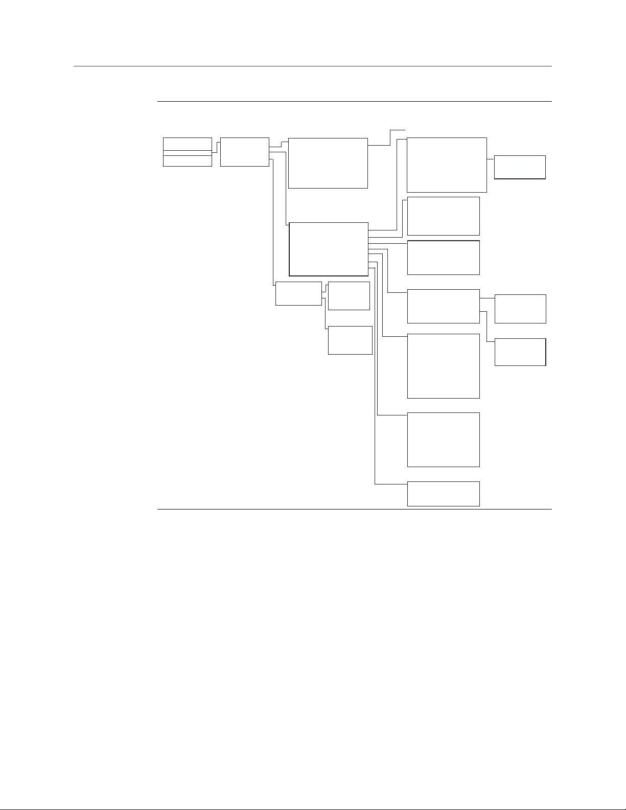
2.4 Field Communicator menu trees
Device Dashboard menu tree
Figure 2-3: Overview
14 Emerson.com/RosemountEmerson.com/Rosemount
Home
1 Overview
2 Configure
3 Service Tools
1 Pressure Alert
2 Temperature Alert
Alert Setup
Configure
1 Guided Setup
2 Manual Setup
3 Alert Setup
Pressure Alert
1 Alert Mode
2 High Alert Value
3 Low Alert Value
Temperature Alert
1 Alert Mode
2 High Alert Value
3 Low Alert Value
Guided Setup
1 Basic Setup
2 Zero
3 Configure Display
4 Variable Mapping
5 Configure Alarm and Sat levels
6 Process Alerts
7 Scaled Variable
Manual Setup
1 Basic Setup
2 Scaled Variable
3 Display
4 HART
5 Device Information
6 Materials of Construction
7 Security
Basic Setup
1 Tag
2 Unit
3 Range Values
4 Transfer Function
5 Pressure Damping
6 Module Temperature Units
7 Configure Alarm and Sat Levels
8 Range by Applying Pressure
Scaled Variable
1 SV Data Points
2 SV Units
3 SV Transfer Function
4 SV Linear Offset
5 SV Config
Display
1 Pressure
2 Scaled Variable
3 Module Temperature
4 Percent of Range
HART
1 Variable Mapping
2 Polling Address
3 Burst Mode
4 Burst Option
Device Information
1 Tag
2 Model
3 Transmitter S/N
4 Date
5 Description
6 Message
7 Model Number 1
8 Model Number 2
9 Model Number 3
Range Values
1 Pressure URV
2 Pressure LRV
Variable Mapping
1 Primary Variable
2 Secondary Variable
3 Third Variable
Materials of Construction
1 Process Connection
2 Process Connection Material
3 Drain Vent Material
4 # of Remote Seals
5 RS Seal Type
6 RS Fill Fluid
7 RS Isolator Material
Security
1 Write Protect Status
2 Local Zero/Span
Burst Option
PV
% range/current
Dyn Vars/current
Tag, Description, Message, Date, Pressure Units,
Temperature Units, Transfer Function, URV, LRV
Reference Manual Configuration
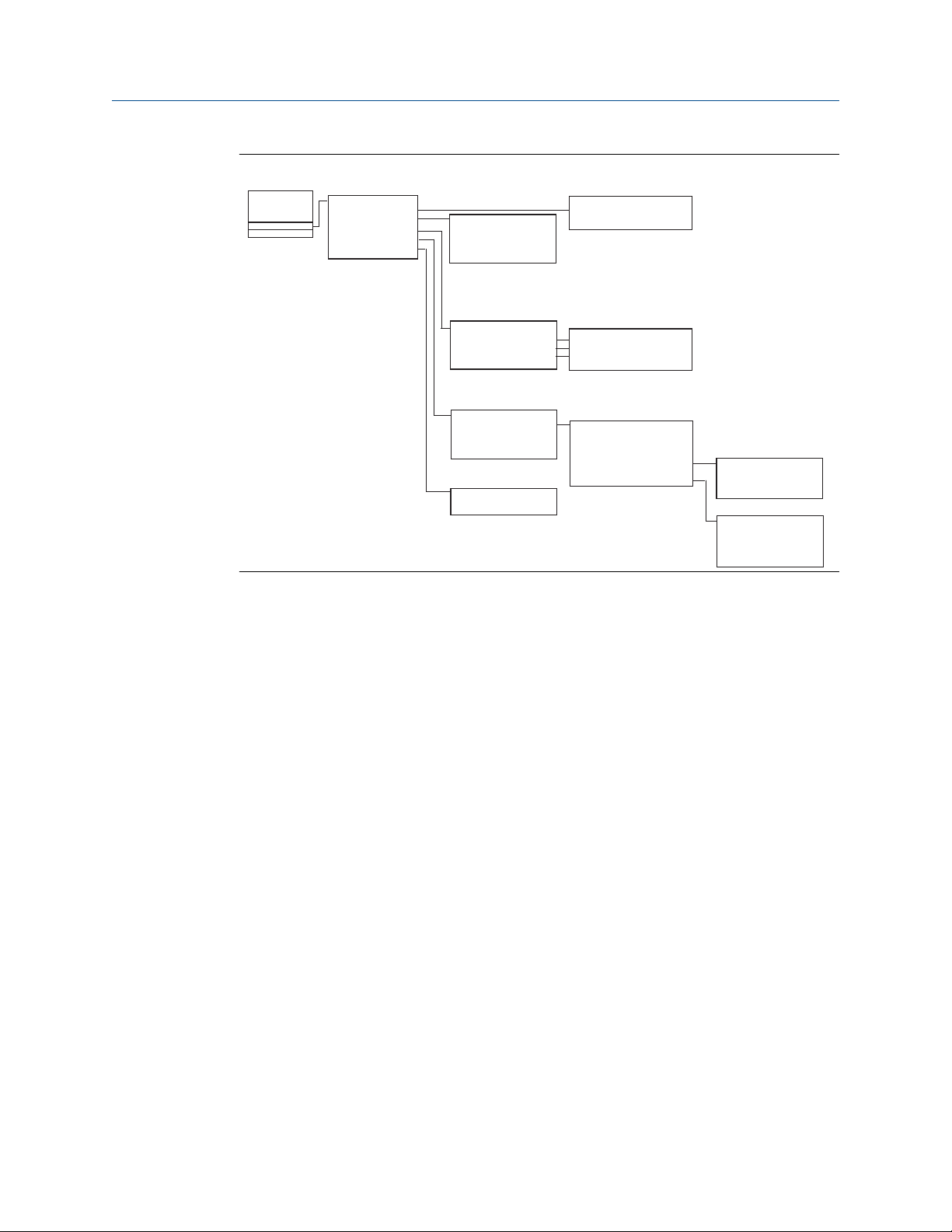
00809-0100-4801 June 2021
Figure 2-4: Configure
15
Home
1 Overview
2 Configure
3 Service Tools
Service Tools
1 Device Alerts
2 Variables
3 Trends
4 Routine Maintenance
5 Simulate
Variables
1 Pressure
2 Scaled Variable
3 Module Temperature
Trends
1 Pressure
2 Scaled Variable
3 Module Temperature
Routine Maintenance
1 Pressure Calibration
2 Analog Output Calibration
3 Recall Factory Calibration
Simulate
1 Loop Test
Device Alerts
1 Refresh Alerts
2 Configuration Changed
Only Active Alerts show up
Trend Graph
Pressure Calibration
1 Upper Sensor Trim
2 Lower Sensor Trim
3 Zero
4 Last Calibration Points
5 Sensor Limits
Last Calibration Points
1 Upper Calibration Point
2 Lower Calibration Point
Sensor Limits
1 Upper
2 Lower
3 Minimum Span
Configuration Reference Manual
June 2021 00809-0100-4801
Figure 2-5: Service Tools
16 Emerson.com/RosemountEmerson.com/Rosemount
Home
1 Overview
2 Configure
3 Service Tools
Overview
1 Status
2 Primary Purpose Variable
3 Shortcuts
Status
1 Device Status: Good
2 Communications: Polled
Shortcuts
1 Calibration
2 SPM Status
3 All Variables
4 View Logs
5 Device Information
Calibration
1 Pressure
2 Analog Output
3 Restore Factory Calibration
Pressure
1 Sensor Calibration
2 Range Values
3 Current Measurement
4 Last Calibration Points
5 Sensor Limits
Primary Purpose Variable
1 Pressure
2 Analog Output
SPM Status
1 Detection Status
2 Statistical Values
3 Time Stamp
4 Trends
Analog Output
1 Analog Output
2 Percent of Range
3 Analog Calibration
Detection Status
1 SPM Status
2 SPM Status (cont.)
3 Standard Deviation Sensitivity*
4 Mean Sensitivity**
*If CV is selected, "Coefficient of Variation Sensitivity"
**If CV is selected, this is not shown
Statistical Values
1 Standard Deviation*
2 Mean
*Or Coefficient of Variation
Time Stamp
1 Time Since Detection
2 Total Operating Time
Trends
1 Standard Deviation*
2 Mean
*If CV is selected, "Coefficient of Variation"
All Variables
1 Primary Variable
2 2nd Variable
3 3rd Variable
4 4th Variable
5 Other Variables
Primary Variable
1 <Mapped variable>
2nd Variable
1 <Mapped variable>
3rd Variable
1 <Mapped variable>
4th Variable
1 <Mapped variable>
Other Variables
1 <Unmapped variable>
2 <Unmapped variable>
Device Information
1 General
2 Model Numbers
3 Revision Numbers
4 Materials of Construction
5 Alarm and Security
View Logs
1 Diagnostic Log
2 Pressure Variable Logging
3 Temperature Variable Logging
Diagnostic Log
1 Most Recent Status Event
2 View Other Status Events
3 Total Operating Time
4 Clear Log
Pressure Variable Logging
1 Pressure Variable Log
2 Time Outside Sensor Limits
3 Pressure
4 Total Operating Time
5 Reset All Pressure Events
Temperature Variable Logging
1 Temperature Variable Log
2 Time Outside Sensor Limits
3 Module Temperature
4 Total Operating Time
5 Reset All Temperature Events
Sensor Calibration
1 Upper Sensor Trim
2 Lower Sensor Trim
3 Zero
Range Values
1 Upper Range value (20 mA)
2 Lower Range Value (4 mA)
Current Measurement
1 Pressure
2 Damping
3 Transfer Function
Last Calibration Points
1 Upper
2 Lower
Sensor Limits
1 Upper
2 Lower
3 Minimum Span
SPM Status (cont.)
1 SPM Insufficient Variability
2 SPM Low Pressure Status
Most Recent Status Event
1 Event 1 - Time since
View Other Status Events
1 Event 2 - Time since
2 Event 3 - Time since
3 Event 4 - Time since
4 Event 5 - Time since
5 Event 6 - Time since
6 Event 7 - Time since
7 Event 8 - Time since
8 Event 9 - Time since
9 Event 10 - Time since
Pressure Variable Log
1 Minimum Pressure
2 Time Since Minimum Event
3 Reset Minimum
4 Maximum Pressure
5 Time Since Maximum Event
6 Reset Maximum
Time Outside Sensor Limits
1 Above Upper Sensor Limit
2 Below Lower Sensor Limit
3 Reset Time Since 1st Events
Temperature Variable Log
1 Minimum Temperature
2 Time Since Minimum Event
3 Reset Minimum
4 Maximum Temperature
5 Time Since Maximum Event
6 Reset Maximum
Time Outside Sensor Limits
1 Above Upper Sensor Limit
2 Below Lower Sensor Limit
3 Reset Time Since 1st Events
General
1 Tag
2 Model
3 Date
4 Descriptor
5 Message
6 Serial Number
Model Numbers
1 Model Number 1
2 Model Number 2
3 Model Number 3
Revision Numbers
1 HART Universal
2 Field Device
3 Electronics SW
4 Electronics HW
5 Sensor SW
6 Sensor HW
Materials of Construction
1 Sensor Module Information
2 Flange Information
3 Remote Seal Information
Alarm and Security
1 Alarm Direction
2 High Alarm
3 High Saturation
4 Low Saturation
5 Low Alarm
6 Write Protect Status
7 Local ZERO/SPAN Buttons
Serial Number
1 Transmitter
2 Electronics
Sensor Module Information
1 Serial Number
2 Type
3 Configuration
4 Sensor Range
5 Sensor Limits
6 Isolator Material
7 Fill Fluid
Flange Information
1 Process Connection
2 Process Connection Material
3 O-ring Material
4 Drain Vent Material
Remote Seal Information
1 Number
2 Type
3 Diaphragm Material
4 Fill Fluid
Reference Manual Configuration
00809-0100-4801 June 2021
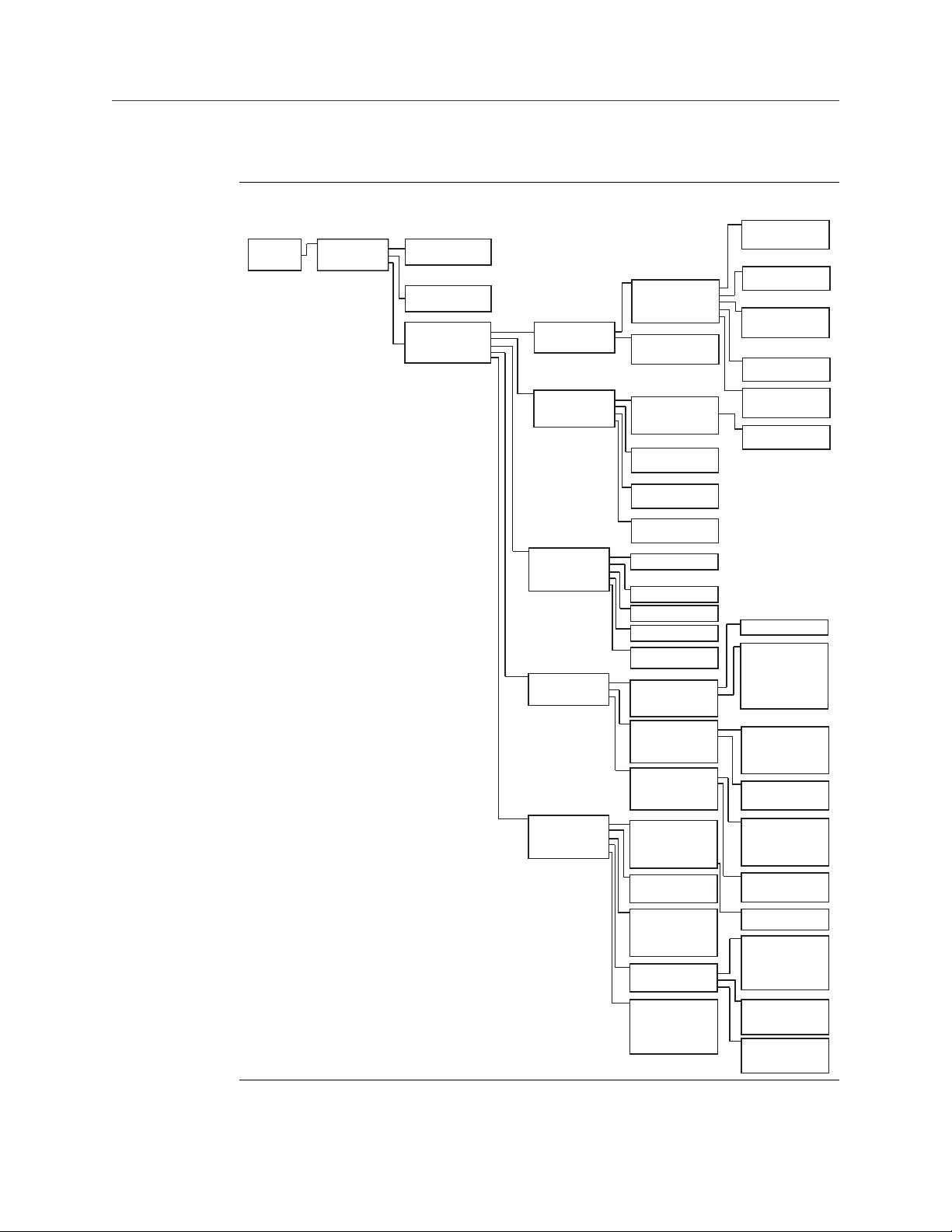
HART 5 with Diagnostic menu trees
Figure 2-6: Overview
17
Home
1 Overview
2 Configure
3 Service Tools
Configure
1 Guided Setup
2 Manual Setup
3 Alert Setup
(see Figure 7-33)
Guided Setup
1 Initial Setup
2 Diagnostics Setup
3 Optional Configuration
Manual Setup
1 Process Variables
2 Analog Output
3 Scaled Variable
4 Display Options
5 HART
6 Security
7 Device Information
Initial Setup
1 Basic Setup
2 Zero Trim
Diagnostics Setup
1 Statistical Process Monitoring
2 Power Advisory
3 Process Alerts
4 Service Alert
Optional Configuration
1 Configure Display
2 Configure Burst Mode
Basic Setup
1 Device Tagging
2 Units of Measure
3 Pressure Damping
4 Variable Mapping
5 Analog Output
6
Config Alarm & Saturation Levels
Display Options
1 Pressure: On or Off
2 Scaled Variable: On or Off
3 Module Temperature: On or Off
4 Percent of Range: On or Off
5 Standard Deviation: On or Off
6 Mean: On or Off
7 Coefficient of Variation: On or Off
Process Variables
1 Pressure Setup
2 Module Temperature Setup
Analog Output
1 Set Range Points
2 Set Range Points Manually
3 Sensor Limits
4 Readings
5 Alarm and Saturation Levels
Pressure Setup
1 Pressure
2 Units
3 Damping
4 Transfer Function
Module Temperature Setup
1 Module Temperature
2 Units
Set Range Points
1 PV Upper Range Value
2 PV Lower Range Value
3 Primary Variable
Set Range Points Manually
1 Range By Applying Pressure
Sensor Limits
1 Upper
2 Lower
3 Minimum Span
Readings
1 Analog Output
2 Percent of Range
Alarm and Saturation Levels
1 Alarm Direction
2 High Alarm
3 High Saturation
4 Low Saturation
5 Low Alarm
6 Config Alarm & Saturation Levels
Scaled Variable Setup
1 Scaled Variable
2 Units
3 Transfer Function
4 Linear Options*
5 Configure Scaled Variable
*If Square Root is selected for Transfer Function,
"Square Root Options"
Linear Options
1 Offset
Square Root Options
1 Cutoff Mode
2 Low Flow Cutoff
Display
1 Display Options
Display Options
1 Pressure: On or Off
2 Scaled Variable: On or Off
3 Module Temperature: On or Off
4 Percent of Range: On or Off
5 Standard Deviation: On or Off
6 Mean: On or Off
7 Coefficient of Variation: On or Off
HART
1 Variable Mapping
2 Burst Mode Configuration
3 Communication Settings
Variable Mapping
1 Primary Variable
2 2nd Variable
3 3rd Variable
4 4th Variable
Burst Mode Configuration
1 Mode
2 Option
Communication Settings
1 Polling Address
Security
1 Write Protect Status
2 Local ZERO/SPAN Buttons
Device Information
1 Identification
2 Flange Information
3 Remote Seal Information
Identification
1 Tag
2 Model
3 Date
4 Descriptor
5 Message
6 Transmitter Serial Number
7 Model Numbers
Flange Information
1 Process Connection
2 Process Connection Material
3 O-ring Material
4 Drain/Vent Material
Remote Seal Information
1 Number
2 Type
3 Diaphragm Material
4 Fill Fluid
Configuration Reference Manual
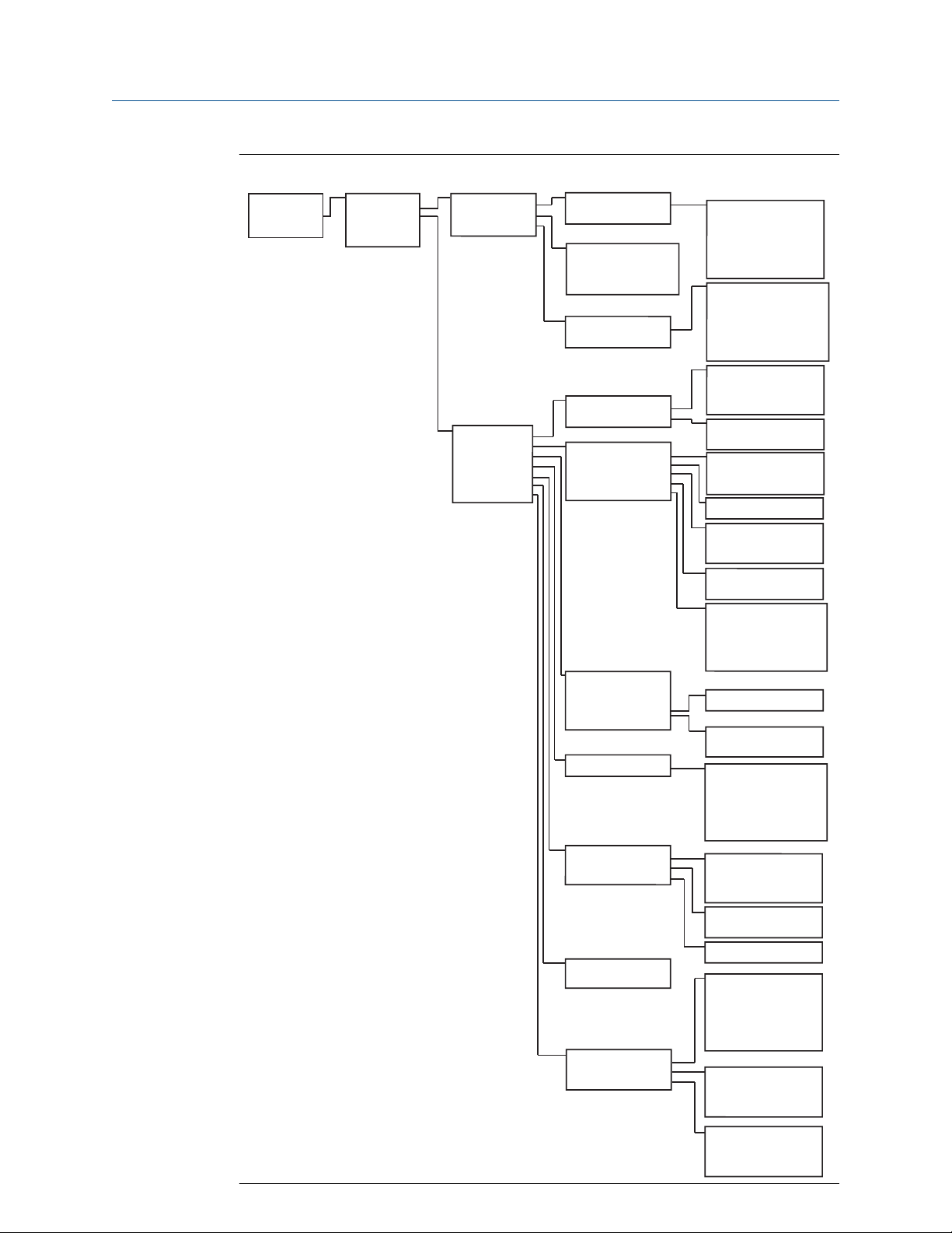
June 2021 00809-0100-4801
Figure 2-7: Configure (Guided Setup and Manual Setup)
18 Emerson.com/RosemountEmerson.com/Rosemount

Home
1 Overview
2 Configure
3 Service Tools
Configure
1 Guided Setup
2 Manual Setup
3 Alert Setup
Alert Setup
1 Statistical Process
Monitoring
2 Power Advisory Diagnostic
3 Device Diagnostics
4 Process Alerts
5 Service Alerts
Statistical Process Monitoring
Status
Baseline Configuration
Detection Configuration
Operational Values
Status
1 Detection Status
2 SPM Control
3 Statistical Values
4 Time Stamp
5 Trends
Detection Status
1 SPM Status
2 SPM Status (cont.)
3 Standard Deviation Sensitivity*
4 Mean Sensitivity**
*If CV is selected, "Coefficient of Variation Sensitivity"
**If CV is selected, this is not shown
SPM Control
1 Mode
2 Reset
3 Relearn
Statistical Values
1 Standard Deviation*
2 Mean
*Or Coefficient of Variation
Time Stamp
1 Time Since Detection
2 Total Operating Time
Trends
1 View Standard Deviation Trend*
2 View Mean Trend
*Or Coefficient of Variation
Baseline Configuration
1 Learn Settings
2 Verification Criteria
Learn Settings
1 SPM Variable
2 Learn/Monitor Period
3 Power Interruption Action
4 Low pressure Cut-off *
*Shown only when CV is selected
Verification Criteria
1 Insufficient Variability
2 Standard Deviation Difference
3 Mean Difference
Detection Configuration
1 Standard Deviation Detection Settings*
2 Mean Detection Settings**
*If CV is selected, "Coefficient of Variation
Detection Settings"
**If CV is selected, this is not shown
Standard Deviation Change*
1 Standard Deviation Sensitivity
2 Threshold Value**
3 Configure Sensitivity
4 Action
5 Alert Delay
6 High Detection Message
7 Low Detection Message
* If CV is selected, “Coefficient of Variation Change”
**Shown only if Sensitivity is set to "Custom"
Mean Change**
1 Mean Sensitivity
2 Threshold Value
3 Configure Sensitivity
4 Action
5 Mean Change Message
**If CV is selected, this is not shown
Operational Values
1 Standard Deviation
2 Mean
3 Coefficient of Variation
4 SPM Detection Values
5 Number of Relearns
6 Reset Relearn Counter
SPM Detection Values
1 Standard Deviation
2 Mean
3 Coefficient of Variation
Power Advisory Diagnostic
1 Power Advisory Diagnostic
2 Loop Power Characterization
Power Advisory Diagnostic
1 Terminal Voltage
2 Terminal Voltage Deviation Limit
3 Action
4 Reset Alert
Loop Power Characterization
1 Resistance
2 Power Supply
3 Characterization Time Stamp
4 Characterize Loop
Resistance
1 Previous Baseline
2 Baseline
Power Supply
1 Previous Baseline
2 Baseline
Characterization Time Stamp
1 Previous Characterization
2 Time Since Characterization
Device Diagnostics
1 mA Output Diagnostic
2 Transmitter Power Consumption
mA Output Diagnostic
1 Action
2 Reset Alert
Transmitter Power Consumption
1 Action
2 Reset Alert
Process Alerts
1 Pressure Alerts
2 Temperature Alerts
Pressure Alerts
1 View Trend
2 Pressure
3 Alert Settings
4 Pressure Alert Events
Temperature Alerts
1 View Trend
2 Module Temperature
3 Alert Settings
4 Module Temperature Alert Events
Service Alerts
1 Time Remaining
2 Message
3 Alert Mode
4 Configure
5 Reset Alert
Alert Settings
1 Alert Mode
2 High Alert Value
3 Low Alert Value
Pressure Alert Events
1 High Alert Events
2 Low Alert Events
3 Reset Alert Events
Alert Settings
1 Alert Mode
2 High Alert Value
3 Low Alert Value
Temperature Alert Events
1 High Alert Events
2 Low Alert Events
3 Reset Alert Events
Reference Manual Configuration
00809-0100-4801 June 2021
Figure 2-8: Configure (Alert Setup)
19

Home
1 Overview
2 Configure
3 Service Tools
Service Tools
1 Device Alerts
2 Variables
3 Trends
4 Routine Maintenance
5 Simulate
Variables
1 Pressure
2 Scaled Variable
3 Module Temperature
Trends
1 Pressure
2 Scaled Variable
3 Module Temperature
Routine Maintenance
1 Pressure Calibration
2 Analog Output Calibration
3 Recall Factory Calibration
Simulate
1 Loop Test
Device Alerts
1 Refresh Alerts
2 Configuration Changed
Only Active Alerts show up
Trend Graph
Pressure Calibration
1 Upper Sensor Trim
2 Lower Sensor Trim
3 Zero
4 Last Calibration Points
5 Sensor Limits
Last Calibration Points
1 Upper Calibration Point
2 Lower Calibration Point
Sensor Limits
1 Upper
2 Lower
3 Minimum Span
Configuration Reference Manual
June 2021 00809-0100-4801
Figure 2-9: Service Tools
20 Emerson.com/RosemountEmerson.com/Rosemount

Reference Manual Configuration
00809-0100-4801 June 2021
HART 7 menu trees
Figure 2-10: Overview
21

Configuration Reference Manual
June 2021 00809-0100-4801
Figure 2-11: Configure (Guided Setup and Manual Setup)
22 Emerson.com/RosemountEmerson.com/Rosemount

Reference Manual Configuration
00809-0100-4801 June 2021
Figure 2-12: Configure (Alert Setup)
23

Configuration Reference Manual
June 2021 00809-0100-4801
Figure 2-13: Service Tools
Device Dashboard Fast Key sequence
The following menu indicates Fast Key sequences for common functions. A check (✓)
indicates the basic configuration parameters. At minimum, these parameters should be
verified as part of the configuration and startup procedure.
Function Fast Key sequence
Alarm and Saturation Levels 1, 4, 5
Alarm Level Configuration 1, 7, 5
Analog Output Alarm Direction 1, 7, 5, 1
Burst Mode Control 2, 2, 4, 3
Burst Option 2, 2, 4, 4
Custom Display Configuration 2, 1, 3
24 Emerson.com/RosemountEmerson.com/Rosemount

Reference Manual Configuration
00809-0100-4801 June 2021
Function Fast Key sequence
✓ Damping 2, 2, 1, 5
Date 2, 2, 5, 4
Descriptor 2, 2, 5, 5
Digital to Analog Trim (4 - 20 mA Output) 3, 4, 2
Disable Zero & Span Adjustment 2, 2, 7, 2
Field Device Information 1, 7
LCD Display Configuration 2, 2, 3
Loop Test 3, 5, 1
Lower Sensor Trim 3, 4, 1, 2
Message 2, 2, 5, 6
Module Temperature/Trend 3, 3, 3
Poll Address 1, 2, 2
Pressure Alert Configuration 2, 3, 1
Range Values 2, 2, 1, 3
Re-mapping 2, 2, 4, 1
Rerange - Keypad Input 1, 5
Rerange with Keypad 2, 2, 1, 3
Saturation Level Configuration 2, 2, 1, 7
Scaled D/A Trim (4–20 mA Output) 3, 4, 2
Scaled Variable Configuration 2, 2, 2
Sensor Information (Materials of Construction) 1, 7, 3
Sensor Trim 3, 4, 1
Sensor Trim Points 3, 4, 1, 4
✓ Tag 2, 2, 5, 1
Temperature Alert Configuration 2, 3, 2
✓ Transfer Function (Setting Output Type) 2, 2, 1, 4
Transmitter Security (Write Protect) 2, 2, 7, 1
✓ Units (Process Variable) 2, 2, 1, 2
Upper Sensor Trim 3, 4, 1, 1
Zero Trim 3, 4, 1, 3
HART 5 with Diagnostics Fast Key sequence
The following menu indicates Fast Key sequences for common functions. A check (✓)
indicates the basic configuration parameters. At minimum, these parameters should be
verified as part of the configuration and startup procedure.
25

Configuration Reference Manual
June 2021 00809-0100-4801
Function Fast Key sequence
Alarm and Saturation Levels 2, 2, 2, 5
Alarm Level Configuration 2, 1, 1, 1, 6
Analog Output Alarm Direction 2, 2, 2, 5, 5, 1
Burst Mode On/Off 2, 2, 5, 2, 1
Burst Option 2, 2, 5, 2, 2
Damping 2, 2, 1, 1, 3
Date 2, 2, 7, 1, 3
Descriptor 2, 2, 7, 1, 4
Digital to Analog Trim (4–20 mA Output) 3, 4, 1, 2, 3
Field Device Information 1, 3, 5
LCD Display Configuration 2, 2, 4
Loop Test 3, 5
Lower Sensor Trim 3, 4, 1, 1, 1, 2
Message 2, 2, 7, 1, 5
Module Temperature 2, 2, 1, 2
Poll Address 2, 2, 5, 3, 1
Pressure Alert Configuration 2, 3, 4, 1, 3
Range Values 3, 4, 1, 1, 2
Re-mapping 2, 2, 5, 1
Rerange - Keypad Input 2, 2, 2, 1
Rerange with Pressure Source 2, 2, 2, 2
Saturation Level Configuration 2, 1, 1, 1, 6
Scaled Variable Configuration 2, 2, 3, 5
Sensor Information 1, 3, 5, 4, 1
Sensor Trim Points 1, 3, 1, 1, 4
✓ Tag 2, 2, 7, 1, 1
Temperature Alert Configuration 2, 3, 4, 2, 3
✓ Transfer Function (Setting Output Type) 2, 2, 1, 1, 4
Transmitter Security (Write Protect) 1, 3, 5, 5, 6
✓ Units (Process Variable) 2, 2, 1, 1, 2
Upper Sensor Trim 3, 4, 1, 1, 1, 1
Zero Trim 3, 4, 1, 1, 1, 3
26 Emerson.com/RosemountEmerson.com/Rosemount

Reference Manual Configuration
00809-0100-4801 June 2021
HART 7 Fast Key sequence
Function Fast Key sequence
Alarm and Saturation Levels 2, 2, 2, 5
Alarm Level Configuration 2, 2, 2, 5, 6
Analog Output Alarm Direction 2, 2, 2, 5, 1
Burst Mode Control 2, 2, 5, 3
Burst Option 2, 2, 5, 3, 1
Damping 2, 2, 1, 1, 3
Date 2, 2, 5, 4
Descriptor 2, 2, 7, 1, 4
Digital to Analog Trim (4–20 mA Output) 3, 4, 1, 2, 3, 1
Disable Zero & Span Adjustment 2, 2, 6, 4
Field Device Information 1, 7
LCD Display Configuration 2, 2, 4
Loop Test 3, 5, 1
Lower Sensor Trim 3, 4, 1, 2
Message 2, 2, 7, 1, 6
Module Temperature/Trend 3, 3, 2
Poll Address 2, 2, 5, 2, 1
Pressure Alert Configuration 2, 3, 4, 1
Range Values 2, 2, 2, 2
Re-mapping 2, 2, 5, 1
Rerange - Keypad Input 2, 2, 2, 2, 1
Rerange with Keypad 2, 2, 2, 3
Saturation Level Configuration 2, 2, 2, 5, 6
Scaled D/A Trim (4–20 mA Output) 3, 4, 1, 2, 3, 2
Scaled Variable Configuration 2, 2, 3, 7
Sensor Information (Materials of Construction) 1, 7, 3, 1
Sensor Trim 3, 4, 1, 1, 1
Sensor Trim Points 3, 4, 1, 1, 4
Tag 2, 2, 7, 1, 1
Temperature Alert Configuration 2, 3, 4, 2
Transfer Function (Setting Output Type) 2, 2, 3, 3
Transmitter Security (Write Protect) 1, 7, 4, 6, 1
Units (Process Variable) 2, 2, 1, 1, 2
27

Configuration Reference Manual
June 2021 00809-0100-4801
Function Fast Key sequence
Upper Sensor Trim 3, 4, 1, 1
Zero Trim 3, 4, 1, 3
2.5 Check output
Before performing other transmitter on-line operations, review the digital output
parameters to ensure that the transmitter is operating properly and is configured to the
appropriate process variables.
2.5.1 Process variables
The process variables for the Rosemount 3051S provide transmitter output, and are
continuously updated. The pressure reading in both engineering units and percent of
range will continue to track with pressures outside of the defined range from the lower to
the upper range limit of the SuperModule™.
View Process Variables on the Field Communicator
Table 2-1: Field Communicator Fast Key Sequences
Device Dashboard Fast Keys 3, 2
HART 5 with Diagnostics Fast Keys 3, 2, 1
HART 7 Fast Keys 3, 2, 2
Enter the Fast Key sequence Process Variables to view the process variables.
Note
Regardless of the range points, the Rosemount 3051S will measure and report all readings
within the digital limits of the sensor. For example, if the 4 and 20 mA points are set to
0 and 10 inH2O, and the transmitter detects a pressure of 25 inH2O, it digitally outputs the
25 inH2O reading and a 250 percent of span reading.
View Process Variables on the AMS Device Manager
Procedure
1. Right click on the device and select Overview from the menu.
2. Select All Variables to display the primary, secondary, tertiary, and quaternary
variables.
2.5.2
28 Emerson.com/RosemountEmerson.com/Rosemount
Module temperature
The Rosemount 3051S contains a temperature sensor near the pressure sensor in the
SuperModule. When reading this temperature, keep in mind module temperature is not a
process temperature reading.

Reference Manual Configuration
00809-0100-4801 June 2021
View the Module Temperature reading on the Field Communicator
Table 2-2: Field Communicator Fast Key Sequences
Device Dashboard Fast Keys 3, 2, 3
HART 5 with Diagnostics Fast Keys 3, 2, 1, 2
HART 7 Fast Keys 3, 2, 2, 2
Enter the Fast Key sequence Module Temperature to view the module temperature
reading.
View the Module Temperature reading on the AMS Device Manager
Procedure
1. Right click on the device and select Overview from the menu.
2. Click All Variables.
2.6 Basic setup
2.6.1 Set Process Variable Units
The PV Unit command sets the process variable units to allow you to monitor your process
using the appropriate units of measure.
Set Process Variable Units on the Field Communicator
Device Dashboard Fast Keys
HART 5 with Diagnostics Fast Keys 2, 2, 1, 1, 2
HART 7 Fast Keys 2, 2, 1, 1, 2
Enter the Fast Key sequence Set Process Variable Units. Select from the following
engineering units:
• inH2O
• inHg • mbar • atm
• ftH2O • g/cm
• mmH2O • kg/cm
• mmHg • Pa • mmH2O at 4 °C
• bar • torr
2
2, 2, 1, 2
• MPa
2
• inH2O at 4 °C
• psi • kPa
29

Configuration Reference Manual
June 2021 00809-0100-4801
Set Process Variable Units on the AMS Device Manager
Procedure
1. Right click on the device and select Configure from the menu.
2. Select Manual Setup from the left window pane.
3. Select the Process Variables tab.
4. Click the Unit drop down menu to select units.
2.6.2 Set output (transfer function)
The Rosemount 3051S has two output settings: linear and square root. Activate the
square root output option to make analog output proportional to flow. As input
approaches zero, the pressure transmitter automatically switches to linear output in order
to ensure a more smooth, stable output near zero (see Figure 2-14 ).
From 0 to 0.6 percent of the ranged pressure input, the slope of the curve is unity (y = x).
This allows accurate calibration near zero. Greater slopes would cause large changes in
output (for small changes at input). From 0.6 to 0.8 percent , curve slope equals 42 (y =
42x) to achieve continuous transition from linear to square root at the transition point.
Note
If low flow cutoff configuration is desired, use Scaled variable configuration to configure
square root and Re-mapping to map the scaled variable as the primary variable.
Note
If scaled variable is mapped as the primary variable and square root mode is selected,
ensure that transfer function is set to linear. Do not set the transfer function to square root
if square root mode is selected for the primary variable as this would cause the square root
function to be performed twice.
Set Output on the Field Communicator
Device Dashboard Fast Keys
HART 5 with Diagnostics Fast Keys 2, 2, 1, 1, 4
HART 7 Fast Keys 2, 2, 1, 1, 4
Procedure
1. Enter the Fast Key sequence for Set Output (Transfer Function).
2. Select Send.
2, 2, 1, 4
Set the Output on the AMS Device Manager
Procedure
1. Right click on the device and select Configure from the menu.
2. Select Manual Setup from the left window pane.
3. Select the Process Variables tab.
30 Emerson.com/RosemountEmerson.com/Rosemount

Reference Manual Configuration
00809-0100-4801 June 2021
4. Select the Transfer Function drop down menu to select output.
Figure 2-14: Square Root Output Transition Point
Note
For a flow turn down of greater than 10:1, it is not recommended to perform a
square root extraction in the transmitter. Instead, perform the square root
extraction in the system. Alternatively, you can configure Scaled Variable for square
root output. This configuration allows you to select a low flow cutoff value, which
will work best for the application. If low flow cutoff configuration is desired, use
Scaled variable configuration to configure square root and Re-mapping to map
scaled variable as the primary variable.
2.6.3
Rerange
The Range Values command sets each of the lower and upper range analog values (4 and
20 mA points) to a pressure. The lower range point represents 0 percent of range and the
upper range point represents 100 percent of range. In practice, the transmitter range
values may be changed as often as necessary to reflect changing process requirements.
For a complete listing of range and sensor limits, refer to the Specifications section of the
Rosemount 3051S Series of Instrumentation Product Data Sheet.
Note
Transmitters are shipped from Emerson fully calibrated per request or by the factory
default of full scale (zero to upper range limit.)
Select from one of the methods below to rerange the transmitter. Each method is unique;
examine all options closely before deciding which method works best for your process.
• Rerange with a Field Communicator or AMS Device Manager only.
• Rerange with a pressure input source and a Field Communicator or AMS Device
Manager.
• Rerange with a pressure input source and the local zero and span buttons (option D1).
Note
If the transmitter security jumper/switch is ON, adjustments to the zero and span cannot
be made. Refer to Wiring the device for security information.
31

Configuration Reference Manual
June 2021 00809-0100-4801
Rerange with a Field Communicator or AMS Device Manager only
The easiest and most popular way to rerange is to use the Field Communicator only. This
method changes the range values of the analog 4 and 20 mA points independently
without a pressure input. This means that when you change either the 4 or 20 mA setting,
you also change the span.
An example for the 4–20 mA HART output:
If the transmitter is ranged so that
4 mA = 0 inH2O, and 20 mA = 100 inH2O,
and you change the 4 mA setting to 50 inH2O using the communicator only, the new
settings are:
4 mA = 50 inH2O, and 20 mA = 100.
Note that the span was also changed from 100 inH2O to 50 inH2O, while the 20 mA
setpoint remained at 100 inH2O.
To obtain reverse output, simply set the 4 mA point at a greater numerical value than the
20 mA point. Using the above example, setting the 4 mA point at 100 inH2O and the 20
mA point at 0 inH2O will result in reverse output.
Rerange on Field Communicators
Device Dashboard Fast Keys
HART 5 with Diagnostics Fast Keys 2, 2, 2, 1
HART 7 Fast Keys 2, 2, 2, 4
From the HOME screen, enter the Fast Key sequence Rerange with a Field Communicator
Only.
Procedure
1. From Keypad Input, select 2 and use the keypad to enter lower range value.
2. From Keypad Input, select 1 and use the keypad to enter upper range value.
3. To complete reranging the transmitter, select Send.
1, 5
Rerange on AMS Device Manager
Procedure
1. Right click on the device and select Configure from the menu.
2. Select Manual Setup from the left window pane.
3. In the Analog Output tab, locate the Configuration box and perform the following
procedure:
a) Enter the lower range value (LRV) and the upper range value (URV) in the
fields provided.
b) Select Send.
32 Emerson.com/RosemountEmerson.com/Rosemount

Reference Manual Configuration
00809-0100-4801 June 2021
c) After carefully reading the warning provided, select Yes.
Rerange with a Pressure Input Source and a Field Communicator or AMS Device Manager
Reranging using the Field Communicator and applied pressure is a way of reranging the
transmitter when specific 4 and 20 mA points are not calculated.
Note
The span is maintained when the 4 mA point is set. The span changes when the 20 mA
point is set. If the lower range point is set to a value that causes the upper range point to
exceed the sensor limit, the upper range point is automatically set to the sensor limit, and
the span is adjusted accordingly.
Rerange with a Pressure Input Source and Field Communicator
Device Dashboard Fast Keys
HART 5 with Diagnostics Fast Keys 2, 2, 2, 2, 1
HART 7 Fast Keys 2, 2, 2, 3
From the HOME screen, enter the Fast Key sequence Rerange with a Pressure Input
Source and a Field Communicator or AMS Device Manager. Follow the on-screen
instructions.
2, 2, 1, 8
Rerange with a Pressure Input Source and AMS Device Manager
Procedure
1. Right click on the device, select Calibrate, then Apply Values from the menu.
2. After the control loop is set to manual, select Next.
3. From the Apply Values menu, follow the on-line instructions to configure lower and
upper range values.
4. Select Exit to leave the Apply Values screen.
5. Select Next to acknowledge the loop can be returned to automatic control.
6. Select Finish to acknowledge the method is complete.
Rerange with a Pressure Input Source and the local zero and span buttons (option D1)
Reranging using the local zero and span adjustments and a pressure source is a way of
reranging the transmitter when specific 4 and 20 mA points are not known and a
communicator is not available.
Note
The span is maintained when the 4 mA point is set. The span changes when the 20 mA
point is set. If the lower range point is set to a value that causes the upper range point to
exceed the sensor limit, the upper range point is automatically set to the sensor limit, and
the span is adjusted accordingly.
33

A B
Configuration Reference Manual
June 2021 00809-0100-4801
To rerange the transmitter using the span and zero buttons, perform the following
procedure:
Procedure
1. Using a pressure source with an accuracy at least four times the desired calibrated
accuracy, apply a pressure equivalent to the lower range value to the high side of
the transmitter.
2. Push and hold the zero adjustment button for at least two seconds but no longer
than 10 seconds.
3. Apply a pressure equivalent to the upper range value to the high side of the
transmitter.
4. Push and hold the span adjustment button for at least two seconds but no longer
than 10 seconds.
Plantweb
™
Junction box
2.6.4
a. Zero
b. Span
Damping
Damping changes the response time of the transmitter; higher values can smooth
variations in output readings caused by rapid input changes. Determine the appropriate
damp setting based on the necessary response time, signal stability, and other
requirements of the loop dynamics of your system. The damping value of your device is
user selectable from 0 to 60 seconds.
Access Damping on the Field Communicator
Device Dashboard Fast Keys
HART 5 with Diagnostics Fast Keys 2, 2, 1, 1, 3
HART 7 Fast Keys 2, 2, 1, 1, 3
Enter the Fast Key sequence Damping.
2, 2, 1, 5
34 Emerson.com/RosemountEmerson.com/Rosemount

Reference Manual Configuration
00809-0100-4801 June 2021
Set the Damping Value in AMS Device Manager
Procedure
1. Right click on the device and select Configure from the menu.
2. Select Manual Setup from the left window pane.
3. In the Process Variables tab, locate Damping and set to desired value.
2.7 LCD display (Optional Order Code)
The LCD display connects directly to the interface/electronics board which maintains
direct access to the signal terminals. The display indicates output and abbreviated
diagnostic messages. A display cover is provided to accommodate the display.
The LCD display features a four-line display and a 0–100 percent scaled bar graph. The first
line of five characters displays the output description, the second line of seven digits
displays the actual value, the third line of six characters displays engineering units and the
fourth line displays “Error” when the transmitter is in alarm. The LCD display can also
display diagnostic messages.
The LCD display configuration command allows customization of the LCD display to suit
application requirements. The LCD display will alternate between the selected items.
2.7.1
2.7.2
Configure the LCD display on the Field Communicator
Device Dashboard Fast Keys 2, 2, 3
HART 5 with Diagnostics Fast Keys 2, 2, 4
HART 7 Fast Keys 2, 2, 4
To configure the LCD display, enter the Fast Key sequence.
Configure the LCD display in AMS Device Manager
Procedure
1. Right click on the device and select Configure from the menu.
2. Select Manual Setup from the left window pane.
3. In the Display tab, select which parameters to show.
2.8 Detailed setup
2.8.1 Failure mode alarm and saturation
Rosemount 3051S Transmitters automatically and continuously perform self-diagnostic
routines. If the self-diagnostic routines detect a failure, the transmitter drives the output
to configured alarm values. The transmitter will also drive the output to configured
saturation values if the applied pressure goes outside the 4–20 mA range values.
35

Configuration Reference Manual
June 2021 00809-0100-4801
The transmitter will drive its output low or high based on the position of the alarm switch.
See Wiring the device.
Note
The failure mode alarm direction can also be configured using the Field Communicator or
AMS Device Manager if hardware switches are not present. See Alarm and saturation level
configuration.
Rosemount 3051S Transmitters have three configurable options for failure mode alarm
and saturation levels:
• Rosemount (Standard), see Table 2-3.
• NAMUR, see Table 2-4.
• Custom, see Table 2-5.
Table 2-3: Rosemount (Standard) Alarm and Saturation Values
Level 4–20 mA saturation 4–20 mA alarm
Low 3.9 mA ≤ 3.75 mA
High 20.8 mA ≥ 21.75 mA
Table 2-4: NAMUR-Compliant Alarm and Saturation Values
Level 4–20 mA saturation 4–20 mA alarm
Low 3.8 mA ≤ 3.6 mA
High 20.5 mA ≥ 22.5 mA
Table 2-5: Custom Alarm and Saturation Values
Level 4–20 mA saturation 4–20 mA alarm
Low 3.7 — 3.9 mA 3.4 — 3.8 mA
High 20.1 — 21.5 mA 20.2 — 23.0 mA
Per Table 2-5, custom alarm and saturation levels can be configured between 3.4 and 3.9
mA for low values and between 20.1 and 23.0 mA for high values. The following
limitations exist for custom levels:
• Low alarm level must be less than the low saturation level
• High alarm level must be higher than the high saturation level
• High saturation level must not exceed 21.5 mA
• Alarm and saturation levels must be separated by at least 0.1 mA
The Field Communicator or AMS Device Manager will provide an error message if a
configuration rule is violated.
36 Emerson.com/RosemountEmerson.com/Rosemount

Reference Manual Configuration
00809-0100-4801 June 2021
2.8.2 Alarm and saturation level configuration
Configure Alarm and Saturation Levels with a Field Communicator
Device Dashboard Fast Keys 2, 2, 1, 7
HART 5 with Diagnostics Fast Keys 2, 2, 2, 5
HART 7 Fast Keys 2, 2, 2, 5
Procedure
1. From the HOME screen, follow the Fast Key sequence.
2. To configure alarm levels, select 6: Config. Alarm and Sat. Levels.
3. Select desired setting.
If OTHER is selected, enter HI and LO custom values.
2.8.3
Configure Alarm and Saturation Levels with AMS Device Manager
Procedure
1. Right click on the device and select Configure from the menu.
2. Select Manual Setup from the left window pane.
3. In the Analog Output tab, select Configure Alarm and Saturation Levels.
4. Follow instructions presented on the screen.
Alarm and saturation levels for burst mode
Transmitters set to burst mode handle saturation and alarm conditions differently.
Alarm conditions
Saturation
• Analog output switches to alarm value
• Primary variable is burst with a status bit set
• Percent of range follows primary variable
• Temperature is burst with a status bit set
• Analog output switches to saturation value
• Primary variable is burst normally
• Temperature is burst normally
2.8.4 Alarm and saturation values for multidrop mode
Transmitters set to multidrop mode handle saturation and alarm conditions differently.
37

Configuration Reference Manual
June 2021 00809-0100-4801
Alarm conditions
Saturation
• Primary variable is sent with a status bit set
• Percent of range follows primary variable
• Module temperature is sent with a status bit set
• Primary variable is sent normally
• Temperature is sent normally
2.8.5 Alarm level verification
The transmitter alarm level should be verified before returning the transmitter to service if
the following changes are made:
• Replacement of electronics board, SuperModule, or LCD display
• Alarm and saturation level configuration
This feature is also useful in testing the reaction of the control system to a transmitter in
an alarm state. To verify the transmitter alarm values, perform a loop test, and set the
transmitter output to the alarm value (see Table 2-3, Table 2-4, Table 2-5, and Loop Test).
2.8.6
Process alerts
Process alerts allow the user to configure the transmitter to output a HART message when
the configured data point is exceeded. Process Alerts can be set for pressure, module
temperature, or both.
A process alert will be transmitted continuously if the pressure or module temperature set
points are exceeded and the alert mode is ON. An alert will be displayed on a Field
Communicator, AMS Device Manager status screen, and in the error section of the LCD
display. The alert will reset once the value returns within range.
Note
HI alert value must be higher than the LO alert value. Both alert values must be within the
pressure or module temperature sensor limits.
Configure the process alerts with a Field Communicator
Device Dashboard Fast Keys
HART 5 with Diagnostics Fast Keys 2, 3, 4
HART 7 Fast Keys 2, 3, 4
Procedure
1. From the HOME screen, follow the Fast Key sequence Process Alerts.
2. To configure the process alerts, select an option.
• To configure the pressure alerts, select 1, Pressure Alerts
• To configure the temperature alerts, select 2, Temperature Alerts
a) To configure the high alert value, select 2, High Alert Value
2, 3
38 Emerson.com/RosemountEmerson.com/Rosemount

Reference Manual Configuration
00809-0100-4801 June 2021
b) To configure the low alert value, select 3, Low Alert Value
3. To enable changes, select Send.
Configure the Process Alerts with AMS Device Manager
Procedure
1. Right click on the device and select Configure from the menu.
2. Select Alert Setup from the left window pane and Process Alerts from the sub-
menu.
3. In the Analog Output tab, enter High Alert Value and Low Alert Value to configure
the pressure alerts.
4. Configure pressure alert mode using the drop down menu.
5. Click Send.
6. In the Temperature Alerts tab, enter High Alert Value and Low Alert Value to
configure the temperature alerts.
7. Configure temperature alert mode using the drop down menu.
8. Click Send.
2.8.7
Scaled variable configuration
The scaled variable configuration allows the user to create a relationship/conversion
between the pressure units and user-defined/custom units.
The scaled variable configuration defines the following items.
Scaled variable
units:
Scaled data
options:
Pressure value
position 1:
Scaled variable
value position 1:
Pressure value
position 2:
Scaled variable
value position 2:
Linear offset:
Custom units to be displayed
Defines the transfer function for the application
1. Linear
2. Square root
Lower known value point (possible 4 mA point) with consideration
of linear offset
Custom unit equivalent to the lower known value point (lower
known value point may or may not be the 4 mA point)
Upper known value point (possible 20 mA point)
Custom unit equivalent to the upper known value point (possible
20 mA point)
Value required to zero out pressures affecting the desired pressure
reading
Low flow cutoff:
Point at which output is driven to zero to prevent problems caused
by process noise. It is highly recommended to use the low flow
cutoff function in order to have a stable output and avoid problems
39

Configuration Reference Manual
June 2021 00809-0100-4801
due to process noise at a low flow or no flow condition. A low flow
cutoff value that is practical for the flow element in the application
should be entered.
Note
If Scaled Variable is mapped as the primary variable and square root mode is selected,
ensure transfer function is set to linear. Refer to Set output (transfer function).
Field Communicator
Device Dashboard Fast Keys 2, 2, 2
HART 5 with Diagnostics Fast Keys 2, 2, 3
HART 7 Fast Keys 2, 2, 3
Procedure
1. From the HOME screen, follow the Fast Key sequence Scaled Variable
Configuration.
2. Select SV Config to configure scaled variable.
Units can be up to five characters long and include A—Z, 0—9, –, /,%, and *. Default
unit is DEFLT. The first character is always an asterisk (*), which identifies the units
displayed are scaled variable units.
3. Select Scaled Data Options.
a) Select Linear if the relationship between PV and scaled Variable units is linear.
Linear prompts for two data points, which results in four values to enter.
b) Select Square Root if the relationship between PV and scaled Variable is
square root (flow applications). Square root will prompt for one data point,
requiring two values to be entered.
4. Enter Pressure Value Position 1.
Pressure values must be within the range of the transmitter.
a) If performing a Linear Function, enter the lower known value point
considering any linear offset.
b) If performing a Square Root Function, select OK to acknowledge pressure
value is set to zero.
5. Enter Scaled Variable Position 1.
a) If performing a Linear Function, enter the lower known value point in terms
of the scaled Variable; this value must be no longer than seven digits.
b) If performing a Square Root Function, select OK to acknowledge scaled
variable value is set to zero.
6. Enter Pressure Value Position 2.
Pressure values must be within the range of the transmitter.
a) Enter the upper known value point in terms of pressure.
40 Emerson.com/RosemountEmerson.com/Rosemount

Reference Manual Configuration
00809-0100-4801 June 2021
7. Enter Scaled Variable Position 2.
a) If performing a Linear Function, enter custom unit equivalent to the upper
known value point; this value must be no longer than seven digits.
b) If performing a Square Root Function, enter the maximum scaled Variable
unit that is equated to the high pressure from step 6; this value must be no
longer than seven digits. Skip to Step 9.
8. If performing a Linear Function, enter linear offset value in pressure units. Skip to
Step 10.
9. If performing a Square Root Function, enter Low Flow Cutoff mode.
a) If a low flow cutoff value is not desired, select OFF.
b) If a low flow cutoff value is desired, select ON and enter this value in scaled
variable (custom) units on the next screen.
10. To acknowledge that the loop can be returned to automatic control, select OK.
Configure the Scaled Variable with AMS Device Manager
Procedure
1. Right click on the device and select Configure from the menu.
2. Select Manual Setup from the left window pane.
3. In the Scaled Variable tab, select Configure Scaled Variable.
4. Follow instructions presented on the screen.
41

Configuration Reference Manual
June 2021 00809-0100-4801
2.8.8 DPLevel example scaled variable
Below is an example of scaled variable in a DP Level application. The Rosemount 3051S
reads the DP in units of inH2O, but the output scaled variable is the height of the liquid in
the tank in inches.
Figure 2-15: Example Tank
A differential transmitter is used in a level application where the span is 188 inH2O (200-in.
0.94 sg). Once installed on an empty tank and taps vented, the process variable reading is
–209.4 inH2O. The process variable reading is the head pressure created by fill fluid in the
capillary. Based on Figure 2-15, the scaled variable configuration would be as follows:
Scaled variable units:
Scaled data options:
Pressure value position 1:
Scaled variable position 1:
Pressure value position 2:
Scaled Variable Position 2:
Linear offset:
Inches
Linear
0 inH2O (0 mbar)
12 in. (305 mm)
188 inH2O (0.47 bar)
212 in. (5385 mm)
–209.4 inH2O (–0.52 bar)
2.8.9 DP Flow example of scaled variable
This DP Flow example of scaled variable takes the DP reading of inH2O, and outputs the
resulting flow in gal/h. Output is scaled with a square root operation internally. The DP
transmitter is used in conjunction with an orifice plate in a flow application where the
differential pressure at full scale flow is 125 inH2O. In this particular application, the flow
42 Emerson.com/RosemountEmerson.com/Rosemount

Reference Manual Configuration
00809-0100-4801 June 2021
rate at full scale flow is 20,000 gallons of water per hour. It is highly recommended to use
the low flow cutoff function in order to have a stable output and avoid problems due to
process noise at a low flow or no flow condition. A low flow cutoff value that is practical for
the flow element in the application should be entered. In this particular example, the low
flow cutoff value is 1000 gallons of water per hour. Based on this information, the Scaled
Variable configuration would be as follows:
2.8.10
Scaled variable units:
Scaled data options:
Pressure value Position 2:
Scaled variable position 2:
Low flow cutoff:
gal/h
Square root
125 inH2O (311 mbar)
20,000 gal/h (75,708 lt/hr)
1000 gal/h (ON)
Note
Pressure Value Position 1 and Scaled Variable Position 1 are always set to zero for a flow
application. No configuration of these values is required.
Re-mapping
The re-mapping function allows the transmitter primary, secondary, tertiary, and
quaternary variables to be configured as desired.
Table 2-6: Default Configuration for Transmitter Variables
HART 5 HART 5 with Diagnostics HART 7
Primary Variable (PV) Pressure
Secondary Variable (SV) Module Temperature
Tertiary Variable (TV) Scaled
Variable
Standard Deviation Scaled Variable
Quaternary Variable (QV) Coefficient of Variation Standard Deviation
Note
The variable assigned as the primary variable drives the 4–20 mA analog output. The
scaled variable can be remapped as the primary variable if desired.
Re-mapping with a Field Communicator
Device Dashboard Fast Keys
HART 5 with Diagnostics Fast Keys 2, 2, 5, 1
HART 7 Fast Keys 2, 2, 5, 1
Procedure
1. From the Home screen, enter the Fast Key sequence Re-mapping.
2. Set the control loop to manual (see Setting the loop to manual).
3. Select desired primary variable and select Enter.
2, 2, 4, 1
43

Configuration Reference Manual
June 2021 00809-0100-4801
4. Select desired secondary variable and select Enter.
5. If using 3051S HART 5 with Diagnostics or 3051S with HART 7, select desired
quaternary variable and select Enter. If using 3051S with HART 5, continue to Step
6.
6. Select Send to complete the changes, then return the loop to automatic control.
7. Select OK to acknowledge that the loop can be returned to automatic control.
Re-mapping with the AMS Device Manager
Procedure
1. Set the control loop to manual (see Setting the loop to manual).
2. Right click on the device and select Configure from the menu.
3. Select Manual Setup from the left window pane.
4. In the HART tab, locate the Variable Mapping box.
5. Select desired primary variable.
6. Select desired secondary variable.
7. Select desired tertiary variable.
8. If using 3015A HART 5 with Diagnostics or 3051S with HART 7, select desired
quarternary variable and select Enter. If using 3051S with HART 5, continue to Step
9.
9. Select Send.
2.8.11
Module temperature unit
The sensor temperature unit command selects between Celsius and Fahrenheit units for
the module temperature.
Note
The module temperature output is accessible via HART only.
Configure the Module Temperature Unit on a Field Communicator
Device Dashboard Fast Keys
HART 5 with Diagnostics Fast Keys 2, 2, 1, 2, 2
HART 7 Fast Keys 2, 2, 1, 2, 2
Enter the Fast Key sequence Module Temperature Unit and select degC for Celsius or
degF for Fahrenheit.
Configure the Module Temperature Unit on a Field
Communicator
Device Dashboard Fast Keys
HART 5 with Diagnostics Fast Keys 2, 2, 1, 2, 2
HART 7 Fast Keys 2, 2, 1, 2, 2
2, 2, 1, 6
2, 2, 1, 6
44 Emerson.com/RosemountEmerson.com/Rosemount

Reference Manual Configuration
00809-0100-4801 June 2021
Enter the Fast Key sequence Module Temperature Unit and select degC for Celsius or
degF for Fahrenheit.
Configure the Module Temperature Unit on AMS Device Manager
Procedure
1. Right click on the device and select Configure from the menu.
2. Select Manual Setup from the left window pane.
3. In the Process Variables tab, locate the Module Temperature Setup box.
4. Use the Units drop down menu to select degF (Fahrenheit) or degC (Celsius).
5. Select Send.
2.9 Diagnostics and service
Diagnostics and service functions listed below are primarily for use after field installation.
The transmitter test feature is designed to verify that the transmitter is operating properly,
and can be performed either on the bench or in the field. The loop test feature is designed
to verify proper loop wiring and transmitter output, and should only be performed after
you install the transmitter.
2.9.1
Loop Test
The Loop Test command verifies the output of the transmitter, the integrity of the loop,
and the operations of any recorders or similar devices installed in the loop.
Initiate a Loop Test on a Field Communicator
Device Dashboard Fast Keys
HART 5 with Diagnostics Fast Keys 3, 5, 1
HART 7 Fast Keys 3, 5, 1
To initiate a Loop Test, perform the following procedure:
Procedure
1. Connect a reference meter to the transmitter by either connecting the meter to the
test terminals on the terminal block, or shunting transmitter power through the
meter at some point in the loop.
2. From the Home screen, enter the Fast Key sequence Loop Test to verify the output
of the transmitter.
3. Select OK after the control loop is set to manual (see Setting the loop to manual).
4. Select a discrete milliamp level for the transmitter to output. At the CHOOSE
ANALOG OUTPUT prompt, select 1: 4mA, 2: 20mA, or 3: “Other” to manually input
a value.
3, 5, 1
45

Configuration Reference Manual
June 2021 00809-0100-4801
a) If you are performing a Loop Test to verify the output of a transmitter, enter a
value between 4 and 20 mA.
b) If you are performing a Loop Test to verify alarm levels, enter the milliamp
value representing an alarm state (see Table 2-1, Table 2-2, and Table 2-3).
5. Check the reference meter installed in the test loop to verify it displays the
commanded output value.
a) If the values match, the transmitter and the loop are configured and
functioning properly.
b) If the values do not match, the current meter may be attached to the wrong
loop, there may be a fault in the wiring, the transmitter may require an
output trim, or the reference meter may be malfunctioning.
After completing the test procedure, the display returns to the loop test screen to choose
another output value or to end loop testing.
Initiate a Loop Test on AMS Device Manager
2.9.2
Procedure
1. Right click on the device and select Service Tools from the menu.
2. Select Simulate from the left window pane.
3. In the Simulate tab, locate and select Loop Test.
4. Follow instructions presented on the screen.
Simulate Device Variables
It is possible to temporarily set the pressure, module temperature, or scaled variable to a
user-defined fixed value for testing purposes. Once the simulated variable method is left,
the process variable will be automatically returned to a live measurement. Simulate Device
Variables is only available with HART Revision 7.
Simulate Device Variables on a Field Communicator
Device Dashboard Fast Keys
HART 5 with Diagnostics Fast Keys N/A
HART 7 Fast Keys 3, 5, 2
From the HOME screen, enter the Fast Key sequence Simulate digital signal with a Field
Communicator.
N/A
Simulate Device Variables on AMS Device Manager
Procedure
1. Right click on the device and select Service Tools from the menu.
2. Select Simulate from the left window pane.
3. Under Device Variables select a digital value to simulate.
46 Emerson.com/RosemountEmerson.com/Rosemount

Reference Manual Configuration
00809-0100-4801 June 2021
• Pressure
• Sensor Temperature
• Scaled Variable
4. Follow the screen prompts to simulate selected digital value.
2.10 Advanced functions
2.10.1 Saving, recalling, and cloning configuration data
Use the cloning feature of the Field Communicator or the AMS Device Manager User
Configuration feature to configure several Rosemount 3051S Transmitters similarly.
Cloning involves configuring a transmitter, saving the configuration data, then sending a
copy of the data to a separate transmitter. Several possible procedures exist when saving,
recalling, and cloning configuration data or AMS Device Manager online guides.
Saving, Recalling, and Cloning Configuration Data on a Field Communicator
Device Dashboard Fast Keys
HART 5 with Diagnostics Fast Keys left arrow, 1, 2
HART 7 Fast Keys left arrow, 1, 2
Procedure
1. Confirm and apply configuration changes to the first transmitter.
2. Save the configuration data.
If transmitter configuration has not been modified, SAVE option will be disabled.
a) From the bottom of the Field Communicator screen, select SAVE.
b) Select to save your configuration on either the Internal Flash (default) or the
System Card.
c) Enter the name for this configuration file.
d) Select SAVE.
3. Power the receiving transmitter and connect with the Field Communicator.
4. Access the HART Application menu by pressing the left arrow from the HOME/
ONLINE screen.
5. Locate the saved transmitter configuration file.
a) Select Offline.
N/A
b) Select Saved Configuration.
c) Select either Internal Flash Contents or System Card Contents depending
on where the configuration was stored.
47

Configuration Reference Manual
June 2021 00809-0100-4801
6. Use the down arrow to scroll through the list of configurations in the memory
module, and use the right arrow to select and retrieve the desired configuration.
7. Select Send to transfer the configuration to the receiving transmitter.
The transmitter receiving cloned data must have the same software version (or
later) as the original transmitter.
8. After the control loop is set to manual, select OK.
9. After the configuration has been sent, select OK to acknowledge that the loop can
be returned to automatic control.
When finished, the Field Communicator informs you of the status. Repeat Step 3 through
Step 9 to configure another transmitter.
Note
The transmitter receiving cloned data must have the same software version (or later) as
the original transmitter.
Creating a Reusable Copy in AMS Device Manager
Create a reusable copy of a configuration.
Procedure
1. Completely configure the first transmitter.
2. Select View.
3. Select User Configurations from the menu (or select the toolbar button)
4. In the User Configurations window, right click and select New from the context
menu.
5. In the New window, select a device from the list of templates shown, and select OK.
6. The template is copied into the User Configurations window with the tag name
highlighted; rename it as appropriate and select Enter.
A device icon can also be copied by dragging and dropping a device template or any
other device icon from Wireless Explorer or Device Connection View into the User
Configurations window.
7. Right click on the copied device and select Configure/Setup from the User
Configurations window.
8. Select Compare from the bottom left window pane.
9. Transfer values from the current configuration to the user configuration as
appropriate or enter values by typing them into the available fields.
10. Select Save to apply the values.
48 Emerson.com/RosemountEmerson.com/Rosemount

Reference Manual Configuration
00809-0100-4801 June 2021
Applying a User Configuration in AMS Device Manager
Any amount of User Configurations can be created for the application. They can also be
saved, and applied to connected devices or to devices in the device list or plant database.
Note
When using AMS Device Manager Revision 6.0 or later, the device to which the user
configuration is applied must be the same model type as the one created in the user
configuration.
Procedure
1. In the User Configurations window, select the desired user configuration.
2. Drag the icon onto a like device in Wireless Explorer or Device Connection View. The
Compare Configurations window opens, showing the parameters of the target
device on one side and the parameters of the user configuration on the other.
3. Transfer parameters from the user configuration to the target device as desired.
Select the Transfer Multiple button to send the configuration and close the
window.
2.10.2
Burst mode
When configured for burst mode, the Rosemount 3051S provides faster digital
communication from the transmitter to the control system by eliminating the time
required for the control system to request information from the transmitter. Burst mode is
compatible with the analog signal. Because the HART protocol features simultaneous
digital and analog data transmission, the analog value can drive other equipment in the
loop while the control system is receiving the digital information. Burst mode applies only
to the transmission of dynamic data (pressure and module temperature in engineering
units, pressure in percent of range, and/or analog output), and does not affect the way
other transmitter data is accessed.
Access to information other than dynamic transmitter data is obtained through the
normal poll/response method of HART communication. A Field Communicator, AMS
Device Manager or the control system may request any of the information that is normally
available while the transmitter is in burst mode. Between each message sent by the
transmitter, a short pause allows the Field Communicator, AMS Device Manager or a
control system to initiate a request. The transmitter will receive the request, process the
response message, and then continue bursting the data approximately three times per
second.
Selecting burst mode options in HART 5
Message content options:
• PV only
• Percent of range/current
• PV, 2V, 3V, 4V
• Process variables
49

Configuration Reference Manual
June 2021 00809-0100-4801
Selecting burst mode options in HART 7
Message content options:
• PV only
• Percent of range/current
• PV, 2V, 3V, 4V
• Process variables and status
• Process variables
• Device status
• All dynamic variables
Selecting a HART 7 trigger mode
When in HART 7 mode, the following trigger modes can be selected.
• Continuous (same as HART5 burst mode)
• Rising
• Falling
• Windowed
• On change
Note
Consult host system manufacturer for burst mode requirements.
Configure Burst Mode for Field Communicator
Enter the Fast Key sequence "Burst Mode" to configure the transmitter for burst mode.
Table 2-7:
Device Dashboard Fast Keys 2, 2, 4, 3
HART 5 with Diagnostics Fast Keys 2, 2, 5, 2
HART 7 Fast Keys 2, 2, 5, 3
AMS Device Manager
1. Right click on the device and select Configure from the menu.
2. Select Manual Setup from the left window pane.
3. Select the HART tab.
4. Enter the configuration in Burst Mode Configuration fields.
50 Emerson.com/RosemountEmerson.com/Rosemount

Reference Manual Configuration
00809-0100-4801 June 2021
2.11 Multidrop communication
Multidropping transmitters refers to the connection of several transmitters to a single
communications transmission line. Communication between the host and the
transmitters takes place digitally with the analog output of the transmitters deactivated.
Multidrop installation requires consideration of the update rate necessary from each
transmitter, the combination of transmitter models, and the length of the transmission
line. Communication with transmitters can be accomplished with Bell 202 modems and a
host implementing HART protocol. Each transmitter is identified by a unique address and
responds to the commands defined in the HART protocol. Field Communicators and AMS
Device Manager can test, configure, and format a multidropped transmitter the same way
as a transmitter in a standard point-to-point installation.
Note
A transmitter in multidrop mode has the analog output fixed at 4 mA. If a meter is installed
to a transmitter in multidrop mode, it will alternate the display between current fixed and
the specified meter output(s).
The Rosemount 3051S is set to address zero (0) at the factory, which allows operation in
the standard point-to-point manner with a 4–20 mA output signal. To activate multidrop
communication, the transmitter address must be changed to a number from 1 to 15 for
HART Revision 5 or 1 to 63 for HART Revision 7. This change deactivates the 4–20 mA
analog output, setting it to 4 mA. It also disables the failure mode alarm signal, which is
controlled by the upscale/downscale switch/jumper position. Failure signals in
multidropped transmitters are communicated through HART messages.
2.11.1
Changing a transmitter address
To activate multidrop communication, the transmitter poll address must be assigned a
number from 1 to 15, and each transmitter in a multidropped loop must have a unique
poll address.
Change a transmitter address with a Field Communicator
Device Dashboard Fast Keys
HART 5 with Diagnostics Fast Keys 2, 2, 5, 3, 1
HART 7 Fast Keys 2, 2, 5, 2, 1
Procedure
1. From the HOME screen, enter the Fast Key sequence Changing a Transmitter
Address and select OK.
2. After removing loop from automatic control, select OK again and enter the address.
Change a transmitter address with AMS Device Manager
Procedure
1. Right click on the device and select Configure from the menu.
2. For HART Revision 5 devices:
1, 2, 2
51

Configuration Reference Manual
June 2021 00809-0100-4801
a) Select Manual Setup and select the HART tab.
b) In the Communications Settings box, enter polling address in the Polling
Address box. Select Send.
3. For HART Revision 7 devices:
a) Select Manual Setup and select the HART tab.
b) Select the Change Polling Address button and follow instructions presented on
the screen.
4. Carefully read the warning and select Yes if it is safe to apply the changes.
2.11.2 Communicating with a multidropped transmitter
To communicate with a multidropped transmitter, the Field Communicator of AMS Device
Manager has to be set up for polling.
Set up the Field Communicator for Polling
Device Dashboard Fast Keys
HART 5 with Diagnostics Fast Keys Left arrow, 3, 1, 2
HART 7 Fast Keys Left arrow, 3, 1, 2
Procedure
1. Select Utility and Configure HART Application.
2. Select Polling Addresses.
3. Enter a polling address.
• For HART Revision 5 devices, enter address 0–15.
• For HART Revision 7 devices, enter address 0–63.
3, 1, 2
Set up the AMS Device Manager for Polling
Procedure
1. Select the HART modem icon.
2. Select Scan All Devices.
52 Emerson.com/RosemountEmerson.com/Rosemount

Reference Manual Hardware Installation
00809-0100-4801 June 2021
3 Hardware Installation
3.1 Overview
The information in this section covers installation considerations for HART® Protocol. The
Rosemount™ 3051S Quick Start Guide for HART is shipped with every transmitter to
describe basic installation, wiring, and startup procedures. Dimensional drawings for each
Rosemount 3051S Pressure Transmitter variation and mounting configuration are
included in the Rosemount 3051S Series of Instrumentation Product Data Sheet.
Note
The following sections contain installation instructions for many optional features. Only
follow a section's directions if the transmitter being installed comes with the features
described.
3.2 Safety messages
Procedures and instructions in this section may require special precautions to ensure the
safety of the personnel performing the operation. Refer to the following safety messages
before performing operations in this section.
WARNING
Explosions
Explosions could result in death or serious injury.
Review the approvals section of this manual for any restrictions associated with a safe
installation.
Before connecting a communicator in an explosive atmosphere, ensure the instruments in
the segment are installed in accordance with intrinsically safe or non-incendive field wiring
practices.
In an explosion-proof/flameproof installation, do not remove the transmitter covers when
power is applied to the unit.
Process leaks
Process leaks may cause harm or result in death.
Install and tighten process connectors before applying pressure.
Electrical shocks
Electrical shock could cause death or serious injury.
Avoid contact with the leads and terminals.High voltage that my be present on leads can
cause electrical shock.
53

Hardware Installation Reference Manual
June 2021 00809-0100-4801
WARNING
Replacement equipment or spare parts not approved by Emerson for use as spare
parts could reduce the pressure retaining capabilities of the transmitter and may
render the instrument dangerous.
Use only bolts supplied or sold by Emerson as spare parts.
Improper assembly of manifolds
Improper assembly of manifolds to traditional flange can damage the SuperModule
Platform.
For safe assembly of manifold to traditional flange, bolts must break black plane of flange
web (i.e., bolt hole) but must not contact module housing.
Physical access
Unauthorized personnel may potentially cause significant damage to and/or
misconfiguration of end users’ equipment. This could be intentional or unintentional and
needs to be protected against.
™
Physical security is an important part of any security program and fundamental to
protecting your system. Restrict physical access by unauthorized personnel to protect end
users’ assets. This is true for all systems used within the facility.
3.3 Considerations
3.3.1 Installation considerations
Measurement performance depends upon proper installation of the transmitter and
impulse piping. Mount the transmitter close to the process and use minimum piping to
achieve best performance. Also, consider the need for easy access, personnel safety,
practical field calibration, and a suitable transmitter environment. Install the transmitter
to minimize vibration, shock, and temperature fluctuation.
Important
Install the enclosed pipe plug (found in the box) in the unused conduit opening. For
straight threads, a minimum of six threads must be engaged. For tapered threads, install
the plug wrench-tight. For material compatibility considerations, see Rosemount Material
Selection Technical Note.
3.3.2
Environmental considerations
Best practice is to mount the transmitter in an environment that has minimal ambient
temperature change. The transmitter electronics temperature operating limits are –40 to
185 °F (–40 to 85 °C). Refer to Rosemount 3051S Series of Instrumentation Product Data
Sheet, which lists the sensing element operating limits. Mount the transmitter so that it is
not susceptible to vibration and mechanical shock and does not have external contact with
corrosive materials.
54 Emerson.com/RosemountEmerson.com/Rosemount

Flow
Flow
Reference Manual Hardware Installation
00809-0100-4801 June 2021
3.3.3 Mechanical considerations
Access requirements and cover installation can help optimize transmitter performance.
See the Rosemount 3051S Series of Instrumentation Product Data Sheet for temperature
operating limits.
Be sure the transmitter is securely mounted. Tilting of the transmitter may cause a zero
shift in the transmitter output.
Side mounted
When the transmitter is mounted on its side, position the coplanar flange to ensure proper
venting or draining. Mount the flange as shown in Figure 3-1, and Figure 3-2 keeping
drain/vent connections on the bottom for gas service and on the top for liquid service.
Figure 3-1: Coplanar Installation Examples
Liquid service
Gas service Steam service
55

Hardware Installation Reference Manual
June 2021 00809-0100-4801
Figure 3-2: In-line Installation Examples
Liquid service Gas service Steam service
3.3.4
Draft range
Installation
For the Rosemount 3051S_CD0 Draft Range Pressure Transmitter, it is best to mount the
transmitter with the isolators parallel to the ground. Installing the transmitter in this way
reduces oil mounting effect and provides for optimal temperature performance.
Reducing process noise
There are two recommended methods of reducing process noise:
• Output damping
• Reference side filtering (in gage applications)
Reference side filtering
In gage applications it is important to minimize fluctuations in atmospheric pressure to
which the low side isolator is exposed. One method of reducing fluctuations in
atmospheric pressure is to attach a length of tubing to the reference side of the
transmitter to act as a pressure buffer.
Another method is to plumb the reference side to a chamber that has a small vent to
atmosphere. If multiple draft transmitters are being used in an application, the reference
side of each device can be plumbed to a chamber to achieve a common gage reference.
3.4 Installation procedures
An overview of the installation steps for a Rosemount 3051S Pressure Transmitter is
depicted in the Figure 3-3. These steps are described in more detail in the following
sections.
56 Emerson.com/RosemountEmerson.com/Rosemount

Reference Manual Hardware Installation
00809-0100-4801 June 2021
Figure 3-3: HART Installation Flowchart
3.4.1 Mount the transmitter
Housing rotation
To improve field access to wiring or to better view the optional LCD display:
57

Hardware Installation Reference Manual
June 2021 00809-0100-4801
1. Loosen the housing rotation set screw.
2. First rotate the housing clockwise to the desired location. If the desired location
cannot be achieved due to thread limit, rotate the housing counter clockwise to the
desired location (up to 360° from thread limit).
3. Re-tighten the housing rotation set screw.
Plantweb housing Junction box housing
A. Set screw
LCD display
In addition to housing rotation, the optional display can be rotated in 90-degree
increments by squeezing the two tabs, pulling out, rotating and snapping back into place.
If the LCD display pins are inadvertently removed from the interface board when the
display is pulled from the housing, carefully remove the pins from the back of the display,
and then re-insert the pins into the interface board. Once the pins are back in place, snap
the display into place. Transmitters ordered with the LCD display will be shipped with the
display installed.
Electronics housing clearance
Mount the transmitter so the terminal side and the LCD display are accessible. Clearance
of 0.75-in. (19 mm) is required for cover removal on the terminal side. Three inches of
clearance is required for cover removal if a LCD display is installed.
Coplanar process connection
Install and tighten all four flange bolts before applying pressure, or process leakage will
result. When properly installed, the flange bolts will protrude through the top of the
sensor module housing. Do not attempt to loosen or remove the flange bolts while the
transmitter is in service.
Procedure
1. Remove the flange bolts.
2. Leaving the flange in place, move the adapters into position with the O-ring
installed.
58 Emerson.com/RosemountEmerson.com/Rosemount

A
B
C
D
Reference Manual Hardware Installation
00809-0100-4801 June 2021
3. Clamp the adapters and the coplanar flange to the transmitter module using the
longer of the bolts supplied.
4. Tighten the bolts. Refer to Table 3-1 for torque specifications.
WARNING
Failure to install proper flange adapter O-rings may cause process leaks, which can
result in death or serious injury. The two flange adapters are distinguished by
unique O-ring grooves. Only use the O-ring that is designed for its specific flange
adapter, as shown below.
Rosemount 3051S/3051/2051
A. Flange adapter
B. O-ring
C. PTFE
D. Elastomer
Whenever you remove flanges or adapters, visually inspect the PTFE O-rings.
Replace them if there are any signs of damage, such as nicks or cuts. If you replace
the O-rings, re-torque the flange bolts after installation to compensate for cold
flow. Refer to the process sensor body reassembly procedure in Reassembly
procedures.
Flange bolt installation
If the transmitter installation requires assembly of the process flanges, manifolds, or
flange adapters, follow these assembly guidelines to ensure a tight seal for optimal
performance characteristics of the transmitters. Use only bolts supplied with the
transmitter or sold by Emerson as spare parts. Figure 3-4 illustrates common transmitter
assemblies with the bolt length required for proper transmitter assembly.
The transmitter can be shipped with a coplanar flange or a traditional flange installed with
four 1.75-in. flange bolts. Stainless steel bolts supplied by Emerson are coated with a
lubricant to ease installation. Carbon steel bolts do not require lubrication. No additional
lubricant should be applied when installing either type of bolt. Bolts supplied by Emerson
are identified by their head markings:
59

Hardware Installation Reference Manual
June 2021 00809-0100-4801
Figure 3-4: Flange Bolt Head Markings
Carbon steel (CS) heading markings
Stainless steel (SST) head markings
Alloy K-500 head marking
The last digit in the F593_head marking may be any letter between A and M.
Bolt installation
Only use bolts supplied with the Rosemount 3051S or sold by Emerson as parts for the
transmitter. The use of non approved bolts could reduce pressure. Use the following bolt
installation procedure:
1. Finger-tighten the bolts.
2. Torque the bolts to the initial torque value using a crossing pattern.
3. Torque the bolts to the final torque value using the same crossing pattern.
Initial and final torque values for the flange and manifold adapter bolts are as follows:
Table 3-1: Torque Values
Bolt material Initial torque value Final torque value
CS-ASTM-A449 Standard 300 in-lb (34 N-m) 650 in-lb (73 N-m)
316 SST—Option L4 150 in-lb (17 N-m) 300 in-lb (34 N-m)
ASTM-A-193-B7M—Option L5 300 in-lb (34 N-m) 650 in-lb (73 N-m)
Alloy K-500 —Option L6 300 in-lb (34 N-m) 650 in-lb (73 N-m)
ASTM-A-453-660—Option L7 150 in-lb (17 N-m) 300 in-lb (34 N-m)
ASTM-A-193-B8M—Option L8 150 in-lb (17 N-m) 300 in-lb (34 N-m)
When installing the transmitter to one of the optional mounting brackets, torque the
mounting bolts to 125 in-lb (14.1 N-m).
60 Emerson.com/RosemountEmerson.com/Rosemount

Reference Manual Hardware Installation
00809-0100-4801 June 2021
Figure 3-5: Flange Bolts and Adapters
Transmitter with flange bolts Transmitters with flange adapters and bolts
Dimensions are in inches (millimeters)
Mounting brackets
Facilitate mounting transmitter to a 2-in. pipe, or to a panel. The B4 Bracket (SST) option is
standard for use with the coplanar and in-line process connections. See Rosemount 3051S
Series of Instrumentation Product Data Sheet for bracket dimensions and mounting
configurations for the B4 option.
Options B1–B3 and B7–B9 are sturdy, epoxy/polyester-painted brackets designed for use
with the traditional flange. The B1–B3 brackets have carbon steel bolts, while the B7–B9
brackets have stainless steel bolts. The BA and BC brackets and bolts are stainless steel.
The B1/B7/BA and B3/B9/BC style brackets support 2-in. pipe-mount installations, and the
B2/B8 style brackets support panel mounting.
Panel mount
Coplanar flange Pipe mount
61

Hardware Installation Reference Manual
June 2021 00809-0100-4801
Traditional flange
3.4.2 Impulse piping
Systems that will use impulse piping should follow the guidance in the following section.
Not all Rosemount 3051S measurement systems will use impulse piping, especially
systems with remote seals, and Rosemount Annubar, compact orifice plates, or an integral
orifice plate. Each of these systems has their own manual to assist with installation.
Mounting requirements
In-line
Impulse piping configurations depend on specific measurement conditions. Refer to
Figure 3-1 and Figure 3-2 for examples of the following mounting configurations:
62 Emerson.com/RosemountEmerson.com/Rosemount

Reference Manual Hardware Installation
00809-0100-4801 June 2021
Liquid
measurement
1. Place taps to the side of the line to prevent sediment deposits
on the transmitter’s process isolators.
2. Mount the transmitter beside or below the taps so gases can
vent into the process line.
3. Mount drain/vent valve upward to allow gases to vent.
Gas
measurement
1. Place taps in the top or side of the line.
2. Mount the transmitter beside or above the taps so liquid will
drain into the process line.
Steam
measurement
1. Place taps to the side of the line.
2. Mount the transmitter below the taps to ensure that the
impulse piping will stay filled with condensate.
3. In steam service above 250 °F (121 °C), fill impulse lines with
water to prevent steam from contacting the transmitter
directly and to ensure accurate measurement start-up.
Steam service
For steam service or for applications with process temperatures greater than the limits of
the transmitter, do not blow down impulse piping through the transmitter. Flush lines
with the blocking valves closed and refill lines with water before resuming measurement.
Refer to Figure 3-1 for correct mounting orientation.
Note
For steam or other elevated temperature services, it is important that temperatures at the
process connection do not exceed the transmitter’s process temperature limits.
Best practices
The piping between the process and the transmitter must accurately transfer the pressure
to obtain accurate measurements. These are some possible sources of error: pressure
transfer, leaks, friction loss (particularly if purging is used), trapped gas in a liquid line,
liquid in a gas line, density variations between the legs, and plugged impulse piping.
The best location for the transmitter in relation to the process pipe is dependent on the
process. Use the following guidelines to determine transmitter location and placement of
impulse piping:
• Keep impulse piping as short as possible.
• For liquid service, slope the impulse piping at least 1 in./ft (8 cm/m) upward from the
transmitter toward the process connection.
• For gas service, slope the impulse piping at least 1 in./ft (8 cm/m) downward from the
transmitter toward the process connection.
• Avoid high points in liquid lines and low points in gas lines.
• Make sure both impulse legs are the same temperature.
• Use impulse piping large enough to avoid friction effects and blockage.
• Vent all gas from liquid piping legs.
63

Hardware Installation Reference Manual
June 2021 00809-0100-4801
• When using a sealing fluid, fill both piping legs to the same level.
• When purging, make the purge connection close to the process taps and purge
through equal lengths of the same size pipe. Avoid purging through the transmitter.
• Keep corrosive or hot (above 250 °F [121 °C]) process material out of direct contact
with the sensor module and flanges.
• Prevent sediment deposits in the impulse piping.
• Maintain equal leg of head pressure on both legs of the impulse piping.
• Avoid conditions that might allow process fluid to freeze within the process flange.
3.4.3 Process connections
Coplanar or traditional process connection
Install and tighten all four flange bolts before applying pressure, or process leakage will
result. When properly installed, the flange bolts will protrude through the top of the
sensor module housing. Do not attempt to loosen or remove the flange bolts while the
transmitter is in service.
Process connections
Coplanar or traditional process connection
Install and tighten all four flange bolts before applying pressure, or process leakage will
result. When properly installed, the flange bolts will protrude through the top of the
sensor module housing. Do not attempt to loosen or remove the flange bolts while the
transmitter is in service.
Coplanar process connection
Install and tighten all four flange bolts before applying pressure, or process leakage will
result. When properly installed, the flange bolts will protrude through the top of the
sensor module housing. Do not attempt to loosen or remove the flange bolts while the
transmitter is in service.
Procedure
1. Remove the flange bolts.
2. Leaving the flange in place, move the adapters into position with the O-ring
installed.
3. Clamp the adapters and the coplanar flange to the transmitter module using the
longer of the bolts supplied.
4. Tighten the bolts. Refer to Table 3-1 for torque specifications.
64 Emerson.com/RosemountEmerson.com/Rosemount

A
B
C
D
Reference Manual Hardware Installation
00809-0100-4801 June 2021
WARNING
Failure to install proper flange adapter O-rings may cause process leaks, which can
result in death or serious injury. The two flange adapters are distinguished by
unique O-ring grooves. Only use the O-ring that is designed for its specific flange
adapter, as shown below.
Rosemount 3051S/3051/2051
A. Flange adapter
B. O-ring
C. PTFE
D. Elastomer
Whenever you remove flanges or adapters, visually inspect the PTFE O-rings.
Replace them if there are any signs of damage, such as nicks or cuts. If you replace
the O-rings, re-torque the flange bolts after installation to compensate for cold
flow. Refer to the process sensor body reassembly procedure in Reassembly
procedures.
In-line process connection
In-line gage transmitter orientation
CAUTION
Equipment damage
Interfering or blocking the atmospheric reference port will cause the transmitter to output
erroneous pressure values.
The low side pressure port (atmospheric reference) on the in-line gage transmitter is
located under the sensor module neck label. See Figure 3-6 .
Keep the vent path free of any obstruction, such as paint, dust, and lubrication by
mounting the transmitter so that any contaminants can drain away.
65

A
Hardware Installation Reference Manual
June 2021 00809-0100-4801
Figure 3-6: In-line Gage Low Side Pressure Port
A. Low side pressure port (under neck label)
3.4.4 Housing rotation
To improve field access to wiring or to better view the optional LCD display:
1. Loosen the housing rotation set screw.
2. First rotate the housing clockwise to the desired location. If the desired location
cannot be achieved due to thread limit, rotate the housing counter clockwise to the
desired location (up to 360° from thread limit).
3. Re-tighten the housing rotation set screw.
Plantweb housing
A. Set screw
Junction box housing
3.5 Rosemount 305, 306, and 304 Manifolds
• The Rosemount 305 Integral Manifold mounts directly to the transmitter and is
available in two styles: traditional and coplanar.
• The Rosemount 306 Integral Manifold is used with in-line transmitters to provide
block-and-bleed valve capabilities of up to 10000 psi (690 bar).
• The Rosemount 304 conventional manifold combines a traditional flange and manifold
that can be mounted to most primary elements.
66 Emerson.com/RosemountEmerson.com/Rosemount

Reference Manual Hardware Installation
00809-0100-4801 June 2021
Figure 3-7: Integral Manifold Designs
3.5.1 Rosemount 305 and 304 Manifold styles
Rosemount 305 Integral Manifold
The Rosemount 305 Integral Manifold is available in two styles: coplanar and traditional.
The traditional Rosemount 305 can be mounted to most primary elements with mounting
adapters.
Figure 3-8: Rosemount 305 Integral Manifold Styles
Coplanar
Traditional
67

Hardware Installation Reference Manual
June 2021 00809-0100-4801
Rosemount 304 Manifolds
The Rosemount 304 comes in two basic styles: traditional (flange + flange and flange +
pipe) and wafer. The Rosemount 304 Traditional Manifold comes in 2-, 3-, and 5-valve
configurations. The Rosemount 304 Wafer Manifold comes in 3- and 5-valve
configurations.
Figure 3-9: Rosemount 304 Manifold Styles
Traditional Wafer
3.5.2 Rosemount 305 Integral Manifold installation procedure
Prerequisites
Inspect the PTFE sensor module O-rings.
• If the O-rings are undamaged, reusing them is recommended.
• If the O-rings are damaged (if they have nicks or cuts, for example), replace them with
new O-rings designed for Rosemount transmitters.
Important
If replacing the O-rings, be careful not to scratch or deface the O-ring grooves or the
surface of the isolating diaphragm when removing the damaged O-rings.
Procedure
1. Install the integral manifold on the sensor module.
a) Finger tighten the bolts.
b) Tighten the bolts incrementally in a cross pattern to final torque value.
68 Emerson.com/RosemountEmerson.com/Rosemount

Reference Manual Hardware Installation
00809-0100-4801 June 2021
See Table 3-1 for complete bolt installation information and for torque values.
When fully tightened, the bolts should extend through the top of the module
housing plane of the flange web (i.e., bolt hole) but must not contact the module
housing.
2. If the PTFE sensor module O-rings have been replaced, the flange bolts should be re-
tightened after installation to compensate for cold flow of the O-rings.
3.5.3
3.5.4
3.5.5
Rosemount 306 Integral Manifold installation procedure
The Rosemount 306 is for use only with a Rosemount 3051S In-line Transmitter.
Assemble the Rosemount 306 to the Rosemount 3051S with a thread sealant. The proper
installation torque v alue for a Rosemount 306 Manifold is 425 in-lb.
Rosemount 304 Conventional Manifold installation
To install a Rosemount 304 Conventional Manifold to a Rosemount 3051 Transmitter:
Procedure
1. Align the Conventional Manifold with the transmitter flange. Use the four manifold
bolts for alignment.
2. Finger tighten the bolts, then tighten the bolts incrementally in a cross pattern to
final torque value. See “Flange bolts” on page 48 for complete bolt installation
information and torque values. When fully tightened, the bolts should extend
through the top of the sensor module housing.
3. Leak-check assembly to maximum pressure range of transmitter.
Manifold operation
WARNING
Process Leaks
Improper installation or operation of manifolds may result in process leaks, which may
cause death or serious injury.
Always perform a zero trim on the transmitter/manifold assembly after installation to
eliminate any shift due to mounting effects.
69

H L
Drain/Vent
valve
Drain/Vent
valve
Isolate
(open)
Isolate
(open)
Process
Equalize
(closed)
H L
Drain/Vent
valve
Isolate
(open)
Drain/Vent
valve
Isolate
(closed)
Process
Equalize
(closed)
H L
Drain/Vent
valve
Isolate
(open)
Drain/Vent
valve
Isolate
(closed)
Process
Equalize
(open)
H L
Drain/Vent
valve
Isolate
(open)
Drain/Vent
valve
Isolate
(closed)
Process
Equalize
(closed)
H L
Drain/Vent
valve
Drain/Vent
valve
Isolate
(open)
Isolate
(open)
Process
Equalize
(closed)
Hardware Installation Reference Manual
June 2021 00809-0100-4801
Coplanar transmitters
Performing zero trim at static line pressure with 3-valve and 5-valve manifolds
In normal operation the two isolate (block) valves between the process ports and
transmitter will be open and the equalize valve will be closed.
Procedure
1. To zero trim the transmitter, close the isolate valve on the low side (downstream)
side of the transmitter.
2. Open the equalize valve to equalize the pressure on both sides of the transmitter.
The manifold is now in the proper configuration for performing a zero trim on the
transmitter.
3. After performing a zero trim on the transmitter, close the equalize valve.
4. Finally, to return the transmitter to service, open the low side isolate valve.
70 Emerson.com/RosemountEmerson.com/Rosemount

H
L
(Plugged)
Isolate
(open)
Isolate
(open)
(Plugged)
Equalize
(closed)
Equalize
(closed)
Process ProcessDrain vent
(closed)
H
L
(Plugged)
Isolate
(open)
Isolate
(closed)
(Plugged)
Process ProcessDrain vent
(closed)
Equalize
(closed)
Equalize
(closed)
(Plugged)
Isolate
(open)
Equalize
(open)
Equalize
(closed)
Process ProcessDrain vent
(closed)
Isolate
(closed)
(Plugged)
H L
Reference Manual Hardware Installation
00809-0100-4801 June 2021
Performing zero trim at static line pressure with 5-valve natural gas manifold
5-valve natural gas configurations shown:
In normal operation, the two isolate (block) valves between the process ports and
transmitter will be open, and the equalize valves will be closed. Vent valves may be opened
or closed.
Procedure
1. To zero trim the transmitter, first close the isolate valve on the low pressure
(downstream) side of the transmitter and the vent valve.
2. Open the equalize valve on the high pressure (upstream) side of the transmitter.
3. Open the equalize valve on the low pressure (downstream) side of the transmitter.
The manifold is now in the proper configuration for performing a zero trim on the
transmitter.
71

(Plugged)
Isolate
(open)
Equalize
(open)
Equalize
(open)
Process ProcessDrain vent
(closed)
Isolate
(closed)
(Plugged)
H L
(Plugged)
Isolate
(open)
Equalize
(open)
Equalize
(closed)
Process ProcessDrain vent
(closed)
Isolate
(closed)
(Plugged)
H L
H
L
(Plugged)
Isolate
(open)
Isolate
(closed)
(Plugged)
Process ProcessDrain vent
(closed)
Equalize
(closed)
Equalize
(closed)
H
L
(Plugged)
Isolate
(open)
Isolate
(open)
(Plugged)
Equalize
(closed)
Equalize
(closed)
Process ProcessDrain vent
(closed)
Hardware Installation Reference Manual
June 2021 00809-0100-4801
4. After performing a zero trim on the transmitter, close the equalize valve on the low
pressure (downstream) side of the transmitter.
5. Close the equalize valve on the high pressure (upstream) side.
6. Finally, to return the transmitter to service, open the low side isolate valve and vent
valve. The vent valve can remain open or closed during operation.
72 Emerson.com/RosemountEmerson.com/Rosemount

Transmitter
Isolate
Vent
(closed)
Process
(open)
Transmitter
Isolate
Vent
(closed)
Process
(closed)
Reference Manual Hardware Installation
00809-0100-4801 June 2021
In-line transmitter
Isolating the transmitter with 2-valve and block and bleed style manifolds
In normal operation the isolate (block) valve between the process port and transmitter will
be open and the test/vent valve will be closed. On a block and bleed style manifold, a
single block valve provides transmitter isolation and a bleed screw provides drain/vent
capabilities.
Procedure
1. To isolate the transmitter, close the isolate valve.
2. To bring the transmitter to atmospheric pressure, open the vent valve or bleed
screw.
Note
Always use caution when venting directly to atmosphere. A ¼-in. male NPT pipe
plug may be installed in the test/vent port and will need to be removed with a
wrench in order to vent the manifold properly.
73

Transmitter
Isolate
Vent
(open)
Process
(closed)
Transmitter
Isolate
Vent
(closed)
Process
(closed)
Transmitter
Isolate
Vent
(closed)
Process
(open)
Hardware Installation Reference Manual
June 2021 00809-0100-4801
3. After venting to atmosphere, perform any required calibration and then close the
test/vent valve or replace the bleed screw.
4. Open the Isolate (block) valve to return the transmitter to service.
3.6 Wiring the device
Remove orange conduit plugs
Use a conduit plug in the unused conduit opening. Thread sealing (PTFE) tape or paste on
male threads of conduit is required to provide a water/dust tight conduit seal and meets
requirements of NEMA® Type 4X, IP66, and IP68. Consult factory if other Ingress
Protection ratings are required.
74 Emerson.com/RosemountEmerson.com/Rosemount

Reference Manual Hardware Installation
00809-0100-4801 June 2021
For M20 threads, install conduit plugs to full thread engagement or until mechanical
resistance is met.
Remove orange plugs from the transmitter conduit openings. The orange plugs are used
to keep the housing free of debris during shipping. They are not meant to be in the
conduit openings when the transmitter is installed and in use.
Install pipe plug in unused conduit opening
Important
Install the enclosed pipe plug (found in the box) in the unused conduit opening.
• For straight threads, a minimum of six threads must be engaged.
• For tapered threads, install the plug wrench-tight.
For material compatibility considerations, refer to Material Selection Technical Note.
3.6.1
Wire the device
Use twisted pairs to yield best results. To ensure proper communication, use 24 to 14
AWG wire, and do not exceed 5000 ft. (1500 m).
Note
Determine local wiring and conduit requirements. Understand local wiring and conduit
requirements prior to installation and be sure to follow all regulations during the
transmitter’s installation.
Figure 3-10: HART Terminal Blocks
Plantweb
Junction Box
Procedure
1. Remove the housing cover on terminal compartment side. Do not remove the
cover in explosive environments when the circuit is live. Signal wiring supplies all
power to the transmitter.
2. Connect the positive lead to the terminal marked (+) and the negative lead to the
terminal marked (PWR/COMM–). Avoid contact with leads and terminals. Do not
75

Hardware Installation Reference Manual
June 2021 00809-0100-4801
connect powered signal wiring to the test terminals. Power could damage the test
diode.
3. Ensure full contact with Terminal Block screw and washer. When using a direct
wiring method, wrap wire clockwise to ensure it is in place when tightening the
terminal block screw.
Note
The use of a pin or ferrule wire terminal is not recommended as the connection may
be more susceptible to loosening over time or under vibration.
4. Plug and seal the unused conduit connection on the transmitter housing to avoid
moisture accumulation in the terminal side. Install wiring with a drip loop. Arrange
the drip loop so the bottom is lower than the conduit connections and the
transmitter housing.
Surges or transients
The transmitter will withstand electrical transients of the energy level usually encountered
in static discharges or induced switching transients. However, high-energy transients,
such as those induced in wiring from nearby lightning strikes, can damage the transmitter.
Optional transient protection terminal block
The transient protection terminal block can be ordered as an installed option (Option
Code T1 in the transmitter model number) or as a spare part to retrofit existing
Rosemount 3051S Transmitters in the field. For a complete listing of spare part numbers
for transient protection terminal blocks, refer to Table 4-2. A lightning bolt symbol on a
terminal block identifies it as having transient protection.
Signal wiring grounding
Do not run signal wiring in conduit or open trays with power wiring, or near heavy
electrical equipment. Grounding terminations are provided on the sensor module and
inside the terminal compartment. These grounds are used when transient protect
terminal blocks are installed or to fulfill local regulations. See below for more information
on how the cable shield should be grounded.
Procedure
1. Remove the field terminals housing cover.
2. Connect the wiring pair and ground as indicated in Figure 3-xx.
a) The terminals are not polarity sensitive.
b) The cable shield should:
• Be trimmed close and insulated from touching the transmitter housing
• Continuously connect to the termination point
• Be connected to a good earth ground at the power supply end
76 Emerson.com/RosemountEmerson.com/Rosemount

DP
C
A
B
B
D
E
Reference Manual Hardware Installation
00809-0100-4801 June 2021
Figure 3-11: Wiring
A. Insulate shield
B. Minimize distance
C. Connect shield back to the power supply ground
D. Trim shield and insulate
E. Safety ground
3. Replace the housing cover. It is recommended that the cover be tightened until
there is no gap between the cover and the housing.
4. Plug and seal unused conduit connections.
Note
A minimum loop resistance of 250 ohms is required to communicate with a Field
Communicator. If a single power supply is used to power more than one
Rosemount 3051S Transmitter, the power supply used, and circuitry common to
the transmitters, should not have more than 20 ohms of impedance at 1200 Hz.
Electrical considerations
Proper electrical installation is necessary to prevent errors due to improper grounding and
electrical noise. For Junction Box housing, shielded signal wiring should be used in high
EMI/RFI environments.
Note
Verify transmitter zero point after installation. To reset zero point, refer to Sensor trim
overview.
Cover installation
Always ensure a proper seal by installing the electronics housing cover(s) so that metal
contacts metal. Use Rosemount O-rings.
77

Hardware Installation Reference Manual
June 2021 00809-0100-4801
3.6.2 Ground the transmitter housing
Transmitter case
Always ground the transmitter case in accordance with national and local electrical codes.
The most effective transmitter case grounding method is a direct connection to earth
ground with minimal impedance. Methods for grounding the transmitter case include an
internal ground connection.
The Internal Ground Connection screw is inside the terminal side of the electronics
housing. The screw is identified by a ground symbol ( ), and is standard on all
Rosemount 3051S Transmitters.
Table 3-2: Option Codes with External Ground Screw Included
Option
code
E1 ATEX Flameproof
N1 ATEX Type n
ND ATEX Dust
E4 TIIS Flameproof
K1 ATEX Flameproof, Intrinsic Safety, Type n, Dust (combination of E1, I1, N1, and ND)
E7 IECEx Flameproof, Dust ignition-proof
N7 IECEx Type n
K7 IECEx Flameproof, Dust ignition-proof, Intrinsic Safety, and Type n (combination of E7, I7, and N7)
KA ATEX and CSA Explosion-proof, Intrinsically Safe, Division 2 (combination of E1, E6, I1, and I6)
KC FM and ATEX Explosion-proof, Intrinsically Safe, Division 2 (combination of E5, E1, I5, and I1)
T1 Transient terminal block
D4 External ground screw assembly
Note
Grounding the transmitter case using the threaded conduit connection may not provide a
sufficient ground. The transient protection terminal block (option code T1) will not
provide transient protection unless the transmitter case is properly grounded. Use the
above guidelines to ground the transmitter case. Do not run transient protection ground
wire with signal wiring; the ground wire may carry excessive current if a lightning strike
occurs.
Description
3.6.3
78 Emerson.com/RosemountEmerson.com/Rosemount
Remote display wiring and power up
The remote mount display and interface system consists of a local transmitter and a
remote mount LCD display assembly. The local Rosemount 3051S Transmitter assembly
includes a Junction Box housing with a three position terminal block integrally mounted to
a SuperModule. The remote mount LCD display assembly consists of a dual compartment
Plantweb housing with a seven position terminal block. See for complete wiring

Reference Manual Hardware Installation
00809-0100-4801 June 2021
instructions. The following is a list of necessary information specific to the remote mount
display system:
• Each terminal block is unique for the remote display system.
• A 316 SST housing adapter is permanently secured to the remote mount LCD display
Plantweb housing providing an external ground and a means for field mounting with
the provided mounting bracket.
• A cable is required for wiring between the transmitter and remote mount LCD display.
The cable length is limited to 100 ft.
• 50 ft. (option M8) or 100 ft. (option M9) cable is provided for wiring between the
transmitter and remote mount LCD display. Option M7 does not include cable. Other
comparable cable may be used as long as it has independent dual twisted shielded pair
wires with an outer shield. The power wires must be 22 AWG minimum and the CAN
communication wires must be 24 AWG minimum.
Note
Cable length may be up to 100 ft. (31 m), depending on cable capacitance. The
capacitance as wired must be less than 5000 picofarads total. This allows up to 50
picofarads per 1 ft. (0.3 m) for a 100 ft. (31 m) cable.
Intrinsic Safety Consideration: The transmitter assembly with remote display has been
approved with Madison AWM Style 2549 cable. Alternate cable may be used as long as the
transmitter with remote display and cable is configured according to the installation
control drawing or certificate. Refer to appropriate approval certificate or control drawing
in for remote cable IS requirements.
Important
Do not apply power to the remote communications terminal. Follow wiring instructions
carefully to prevent damage to system components.
Important
For ambient temperatures above 140 °F (60 °C), cable wiring must be rated at least 9 °F (5
°C) above the maximum ambient temperature.
79

(white) 24 AWG
(blue) 24 AWG
(black) 22 AWG
(red) 22 AWG
4-20 mA
Hardware Installation Reference Manual
June 2021 00809-0100-4801
Figure 3-12: Remote Mount Display Wiring Diagram
Junction Box housing Remote mount display
3.6.4
80 Emerson.com/RosemountEmerson.com/Rosemount
Note
Wire colors provided above are per Madison AWM Style 2549 cable. Wire color may vary
depending on cable selected.
Madison AWM Style 2549 cable includes a ground shield. This shield must be connected to
earth ground at either the SuperModule™ or the Remote Display, but not both.
eurofast®/minifast® connection
For Rosemount 3051S Transmitters with conduit electrical connectors GE or GM, refer to
the cordset manufacturer’s installation instructions for wiring details. For FM Intrinsically
Safe, non-incendive or FM FISCO Intrinsically Safe hazardous locations, install in

A
B
C
D
E
F
Reference Manual Hardware Installation
00809-0100-4801 June 2021
accordance with Rosemount drawing 03151-1009 to maintain outdoor rating (NEMA® and
IP66).
Reassembly of conduit receptacles
If the conduit receptacle is removed or replaced, follow the instructions below to re-wire
the GE or GM conduit receptacle to the terminal block:
Procedure
1. Connect the green/yellow lead wire to the internal ground screw.
2. Connect the brown lead wire to the terminal marked (+).
3. Connect the blue lead wire to the terminal marked (pwr/comm-).
3.6.5
Quick Connect wiring
As standard, the Rosemount 3051S Quick Connect arrives properly assembled to the
SuperModule and is ready for installation. Cordsets and Field Wireable Connectors (in
shaded area) are sold separately.
Figure 3-13: Quick Connect Exploded View
A. Quick Connect housing
B. Straight field wireable connector
C. Right angle field wireable connector
D. Cordset
E. Cordset/field wireable coupling nut
F. Quick Connect coupling nut
(4)
(1) (2)
(3)(2)
(1) Order part number 03151-9063-0001.
(2) Field wiring supplied by customer.
(3) Order part number 03151-9063-0002.
(4) Supplied by cordset vendor.
81

A
+
-
B
Hardware Installation Reference Manual
June 2021 00809-0100-4801
Important
If Quick Connect is ordered as a 300S spare housing or is removed from the SuperModule,
follow the instructions for proper assembly prior to field wiring.
Procedure
1. Place the Quick Connect onto the SuperModule. To ensure proper pin alignment,
remove coupling nut prior to installing quick Connect onto SuperModule.
2. Place coupling nut over quick connect and wrench tighten to a maximum of 300 in-
lb (34 N-m).
3. Tighten the set screw using a 3/32-in. hex wrench.
4. Install cordset/Field Wireable Connectors onto the Quick Connect. Do not over
tighten.
Figure 3-14: Quick Connect Housing Pin-Out
3.6.6
3.6.7
A. Ground
B. No connection
For other wiring details, refer to pin-out drawing and the cordset manufacturer’s
installation instructions.
Power the transmitter
Power supply 4–20 mA transmitters
The dc power supply should provide power with less than two percent ripple. Total
resistance load is the sum of resistance from signal leads and the load resistance of the
controller, indicator, and related pieces. Note the resistance of intrinsic safety barriers, if
used, must be included.
Cover jam screw
For transmitter housings shipped with a cover jam screw, as shown in Figure 3-15, the
screw should be properly installed once the transmitter has been wired and powered up.
The cover jam screw is intended to disallow the removal of the transmitter cover in
flameproof environments without the use of tooling.
Procedure
1. Verify the cover jam screw is completely threaded into the housing.
82 Emerson.com/RosemountEmerson.com/Rosemount

Reference Manual Hardware Installation
00809-0100-4801 June 2021
2. Install the transmitter housing cover and verify that the cover is tight against the
housing.
3. Using an M4 hex wrench, loosen the jam screw until it contacts the transmitter
cover.
4. Turn the jam screw an additional ½ turn counterclockwise to secure the cover.
Note
Application of excessive torque may strip the threads.
5. Verify the cover cannot be removed.
Figure 3-15: Cover Jam Screw
Plantweb housing
A. 2x cover jam screw (1 per side)
B. Cover jam screw
Junction Box housing
83

Hardware Installation Reference Manual
June 2021 00809-0100-4801
84 Emerson.com/RosemountEmerson.com/Rosemount

Reference Manual Operation and maintenance overview
00809-0100-4801 June 2021
4 Operation and maintenance
overview
This section contains information on commissioning and operating Rosemount™ 3051S
Pressure Transmitters. Tasks that should be performed on the bench prior to installation
are explained in this section.
Field Communicator and AMS Device Manager instructions are given to perform
configuration functions. For convenience, Field Communicator Fast Key sequences are
labeled Fast Keys for each software function below the appropriate headings.
4.1 Calibration for HART® Protocol
Calibrating a Rosemount 3051S Transmitter may include the following procedures:
• Rerange: Sets the 4 and 20 mA points at required pressures.
• Sensor trim: Adjusts the position of the factory sensor characterization curve to
optimize performance over a specified pressure range, or to adjust for mounting
effects.
• Analog output trim: Adjusts the analog output to match the plant standard or the
control loop.
The Rosemount 3051S SuperModule™ uses a microprocessor that contains information
about the sensor’s specific characteristics in response to pressure and temperature inputs.
A smart transmitter compensates for these sensor variations. The process of generating
the sensor performance profile is called factory sensor characterization. Factory sensor
characterization also provides the ability to readjust the 4 and 20 mA points without
applying pressure to the transmitter.
Trim and rerange functions also differ. Reranging sets analog output to the selected upper
and lower range points and can be done with or without an applied pressure. Reranging
does not change the factory sensor characterization curve stored in the microprocessor.
Sensor trimming requires an accurate pressure input and adds additional compensation
that adjusts the position of the factory sensor characterization curve to optimize
performance over a specific pressure range.
Note
Sensor trimming adjusts the position of the factory sensor characterization curve. It is
possible to degrade performance of the transmitter if the trim is done improperly or with
inaccurate equipment.
85

Operation and maintenance overview Reference Manual
June 2021 00809-0100-4801
Table 4-1: Recommended Calibration Tasks
Transmitter Bench calibration tasks Field calibration tasks
Rosemount
3051S_ CD,
3051S_ CG,
3051S_SAL,
3051S_SAM,
3051S_TG, Range
1–4
Rosemount
3051S_ CA,
3051S_ TA,
3051S_ TG,
Range 5
• Set output configuration
parameters:
Set the range points.
Set the output units.
Set the output type.
Set the damping value.
• Optional: Perform a sensor trim
(accurate pressure source
required).
• Optional: Perform an analog
output trim (accurate multimeter
required).
• Set output configuration
parameters:
Set the range points.
Set the output units.
Set the output type.
Set the damping value.
• Optional: Perform a sensor trim if
equipment available (accurate
absolute pressure source
required). Otherwise, perform the
low trim value section of the
sensor trim procedure.
• Optional: Perform an analog
output trim (accurate multimeter
required).
• Reconfigure parameters if
necessary.
• Zero trim the transmitter to
compensate for mounting effects
or static pressure effects.
• Reconfigure parameters if
necessary.
• Perform low trim value section of
the sensor trim procedure to
correct for mounting position
effects.
Note
A Field Communicator is required for all sensor and output trim procedures. Rosemount
3051S_C Range 4 and Range 5 Transmitters require a special calibration procedure when
used in differential pressure applications under high static line pressure (see ). Rosemount
3051S_TG Range 5 Transmitters use an absolute sensor that requires an accurate absolute
pressure source to perform the optional sensor trim.
4.1.1
Calibration overview
Complete calibration of the Rosemount 3051S involves the following tasks:
Configure the analog output parameters
• Set Process Variable Units
• Set Output Type
• Rerange
86 Emerson.com/RosemountEmerson.com/Rosemount

Reference Manual Operation and maintenance overview
00809-0100-4801 June 2021
• Set Damping
Calibrate the sensor
• Sensor Trim
• Zero Trim
Calibrate the 4–20 mA output
• 4–20 mA Output Trim; or
• 4–20 mA Output Trim Using Other Scale
Data flow
Not all calibration procedures should be performed for each transmitter. Some procedures
are appropriate for bench calibration, but should not be performed during field
calibration. Table 4-1 identifies the recommended calibration procedures for each type of
transmitter for bench or field calibration. Data flow can be summarized in four major
steps:
1. A change in pressure is measured by a change in the sensor output (sensor signal).
4.1.2
2. The sensor signal is converted to a digital format that is understood by the
microprocessor (Analog-to-Digital signal conversion).
3. Corrections are performed in the microprocessor to obtain a digital representation
of the process input (Digital PV).
4. The Digital PV is converted to an analog value (Digital-to-Analog signal conversion).
Determining calibration frequency
Calibration frequency can vary greatly depending on the application, performance
requirements, and process conditions.
Procedure
1. Determine the performance required for your application.
2. Determine the operating conditions.
3. Calculate the Total Probable Error (TPE).
4. Calculate the stability per month.
5. Calculate the calibration frequency.
Sample calculation
Procedure
1. Determine the performance required for your application.
Required performance:
2. Determine the operating conditions.
Transmitter:
Rosemount 3051S_CD, range 2A [URL= 250
inH2O(623 mbar)], classic performance
0.30% of span
87

Operation and maintenance overview Reference Manual
June 2021 00809-0100-4801
Calibrated span: 150 inH2O (374 mbar)
Ambient temperature
± 50 °F (28 °C)
change:
Line pressure: 500 psig (34.5 bar)
3. Calculate TPE.
Example
TPE =
0.112% of span
Where:
Reference accuracy = ± 0.055% of span
Ambient temperature effect =
Span static pressure effect
(1) Zero static pressure effect removed by zero trimming at line pressure.
(1)
=
=
4.1.3
4. Calculate the stability per month.
Example
5. Calculate calibration frequency.
Example
Selecting a trim procedure
Prerequisites
To decide which trim procedure to use, you must first determine whether the analog-todigital section or the digital-to-analog section of the transmitter electronics needs
trimming.
88 Emerson.com/RosemountEmerson.com/Rosemount

Reference Manual Operation and maintenance overview
00809-0100-4801 June 2021
Procedure
1. Connect a pressure source, a Field Communicator or AMS Device Manager, and a
digital readout device to the transmitter.
2. Establish communication between the transmitter and the Field Communicator.
3. Apply pressure equal to the upper range point pressure.
4. Compare the applied pressure to the pressure process variable value.
• On the Field Communicator, access the pressure process variable value on the
Process Variables menu.
• On the AMS Device Manager, access the pressure process variable on the
Process Variables screen.
a) If the pressure reading does not match the applied pressure (with high-
accuracy test equipment), perform a sensor trim. See to determine which
trim to perform.
For instructions on how to access process variables, see .
5. Compare the Analog Output (AO) line, on the Field Communicator or AMS Device
Manager, to the digital readout device.
a) If the AO reading does not match the digital readout device (with high-
accuracy test equipment), perform an analog output trim. See .
4.1.4
Sensor trim overview
Trim the sensor using either sensor or zero trim functions. Trim functions vary in
complexity and are application-dependent. Both trim functions alter the transmitter’s
interpretation of the input signal.
Zero trim is a single-point offset adjustment. It is useful for compensating for mounting
position effects and is most effective when performed with the transmitter installed in its
final mounting position. Since this correction maintains the slope of the characterization
curve, it should not be used in place of a sensor trim over the full sensor range.
When performing a zero trim with a manifold, refer to Manifold operation on page xx .
Note
Do not perform a zero trim on Rosemount 3051S Absolute Pressure Transmitters. Zero
trim is zero based, and absolute pressure transmitters reference absolute zero. To correct
mounting position effects on an absolute pressure transmitter, perform a low trim within
the sensor trim function. The low trim function provides an offset correction similar to the
zero trim function, but it does not require zero-based input.
Sensor trim is a 2-point sensor calibration where two end-point pressures are applied, and
all output is linearized between them. Always adjust the low trim value first to establish
the correct offset. Adjustment of the high trim value provides a slope correction to the
characterization curve based on the low trim value. The trim values allow you to optimize
performance over your specified measuring range at the calibration temperature.
89

Operation and maintenance overview Reference Manual
June 2021 00809-0100-4801
4.1.5 Zero trim
Device Dashboard Fast Keys 3, 4, 1, 3
HART 5 with Diagnostics Fast Keys 3, 4, 1, 1, 1, 3
HART 7 Fast Keys 3, 4, 1, 1, 1, 3
Note
The transmitter must be within three percent of true zero (zero-based) in order to
calibrate with zero trim function.
Calibrate the sensor with the Field Communicator Zero Trim Function
Calibrate the sensor with a Field Communicator using the zero trim function
Procedure
1. Vent the transmitter and attach a Field Communicator to the measurement loop.
2. From the HOME screen, follow the Fast Key sequence Zero Trim.
3. Follow the commands provided by the Field Communicator to complete the zero
trim adjustment.
4.1.6
Calibrate the sensor with the AMS Device Manager Zero Trim Method
Procedure
1. Right click on the device and from the menu, select Methods.
2. Select Calibrate.
3. Select Zero Trim.
4. Follow the on-screen prompts.
5. Select Finish to acknowledge the method is complete.
Sensor trim
Device Dashboard Fast Keys 3, 4, 1
HART 5 with Diagnostics Fast Keys 3, 4, 1, 1, 1
HART 7 Fast Keys 3, 4, 1, 1, 1
Note
Use a pressure input source that is at least four times more accurate than the transmitter,
and allow the input pressure to stabilize for 10 seconds before entering any values.
90 Emerson.com/RosemountEmerson.com/Rosemount

Reference Manual Operation and maintenance overview
00809-0100-4801 June 2021
Calibrate the Field Communicator with the Sensor Trim Function
Calibrate the sensor with a Field Communicator using the sensor trim function.
Procedure
1. Assemble and power the entire calibration system including a transmitter, Field
Communicator, power supply, pressure input source, and readout device.
2. From the home screen, enter the Fast Key sequence Sensor Trim.
3. Select 2: Lower Sensor Trim. The lower sensor trim value should be the sensor trim
point that is closest to zero.
Note
Select pressure input values so that lower and upper values are equal to or outside
the 4 and 20 mA points. Do not attempt to obtain reverse output by reversing the
high and low points. This can be done by going to "Rerange". The transmitter allows
approximately five percent deviation.
4. Follow the commands provided by the Field Communicator to complete the
adjustment of the lower value.
5. Repeat for the upper value. In step 3, select 3: Upper Sensor Trim.
4.1.7
Calibrate the Transmitter with the AMS Device Manager Sensor Trim Method
Procedure
1. Right click on the device and select Methods, then Calibrate, then Sensor Trim
from the menu.
2. Select Lower Sensor Trim.
3. Follow on-screen prompts.
4. Select Finish to acknowledge the method is complete.
5. Right click on the device and select Methods, then Calibrate, then Sensor Trim
from the menu.
6. Select Upper Sensor Trim and repeat steps 3-4.
Recall factory trim–sensor trim
Device Dashboard Fast Keys 3, 4, 3
HART 5 with Diagnostics Fast Keys 3, 4, 1, 3, 1
HART 7 Fast Keys 3, 4, 1, 3, 1
The recall factory trim–sensor trim command allows the restoration of the as-shipped
factory settings of the sensor trim. This command can be useful for recovering from an
inadvertent zero trim of an absolute pressure unit or inaccurate pressure source.
91

Operation and maintenance overview Reference Manual
June 2021 00809-0100-4801
Recall Factor Trim on a Field Communicator
Enter the Fast Key sequence “Recall Factory Trim–Sensor Trim”.
Recall Factory Trim on AMS Device Manager
Recall factory sensor trim on the AMS Device Manager.
Procedure
1. Right click on the device and select Methods, then Calibrate, then Recall Factory
Trim from the menu.
2. Set the control loop to manual, then select Next.
3. To recall the factory trim settings, on the Trim to recall menu, select Sensor trim
and then select Next.
4. Follow the on-screen prompts.
5. To acknowledge the method is complete, select Finish .
4.1.8
4.1.9
Analog output trim
The analog output trim commands allow you to adjust the transmitter’s current output at
the 4 and 20 mA points to match the plant standards. This command adjusts the Digitalto-Analog signal conversion.
Digital-to-Analog trim
Device Dashboard Fast Keys 3, 4, 2
HART 5 with Diagnostics Fast Keys 3, 4, 1, 2, 3
HART 7 Fast Keys 3, 4, 1, 2, 3, 1
Perform a Digital-to-Analog Trim with a Field Communicator
To perform a digital-to-analog trim with a Field Communicator.
Procedure
1. From the Home screen, enter the Fast Key sequence Digital-to-Analog Trim.
2. Select OK after setting the control loop to manual. See Setting the loop to manual.
3. At the Connect reference meter prompt, connect an accurate reference milliamp
meter to the transmitter.
a) Connect the positive lead to the positive terminal.
b) Connect the negative lead to the test terminal in the transmitter terminal
compartment.
4. Select OK after connecting the reference meter.
5. At the Setting fld dev output to 4 mA prompt, select OK.
The transmitter outputs 4.0 mA.
92 Emerson.com/RosemountEmerson.com/Rosemount

Reference Manual Operation and maintenance overview
00809-0100-4801 June 2021
6. Record the actual value from the reference meter, and enter it at the ENTER METER
VALUE prompt.
The Field Communicator prompts you to verify whether or not the output value
equals the value on the reference meter.
7. Select an option.
• If the reference meter value equals the transmitter output value, select 1: Yes
and then continue with step Step 8 .
• If the reference meter value does not equal the transmitter output value, select
2: No and repeat step Step 6.
8. At the Setting fld dev output to 20 mA prompt, select OK. Repeat Step 5 and Step 6
until the reference meter value equals the transmitter output value.
9. Select OK after the control loop is returned to automatic control.
Calibrate the Transmitter using the AMS Device Manager Digital-to-Analog Trim Method
Procedure
4.1.10
1. Right click on the device and select Methods, then Calibrate, then D/A Trim from
the menu.
2. Follow the on-screen prompts.
3. Select Finish to acknowledge the method is complete.
Digital-to-Analog trim using other scale
Device Dashboard Fast Keys 3, 4, 2, 2
HART 5 with Diagnostics Fast Keys N/A
HART 7 Fast Keys 3, 4, 1, 2, 3, 2
The scaled D/A trim command matches the 4 and 20 mA points to a user selectable
reference scale other than 4 and 20 mA (i.e., 1–5 volts if measuring across a 250 ohm load,
or 0–100 percent if measuring from a Distributed Control System [DCS]). To perform a
scaled D/A trim, connect an accurate reference meter to the transmitter and trim the
output signal to scale, as outlined in the output trim procedure.
Note
Use a precision resistor for optimum accuracy. If you add a resistor to the loop, ensure that
the power supply is sufficient to power the transmitter to a 23 mA output (maximum
alarm value) with additional loop resistance.
Field Communicator
Enter the Fast Key sequence “Digital-to-Analog Trim Using Other Scale”.
93

Operation and maintenance overview Reference Manual
June 2021 00809-0100-4801
Use the Scaled D/A Trim method on AMS Device Manager
Procedure
1. Right click on the device and select Methods, then Calibrate, then Scaled D/A trim
from the menu.
2. Set the control loop to manual, select Next.
3. To change the scale, select Change and then select Next.
4. Follow the on-screen prompts.
5. To acknowledge the method is complete, select Finish.
4.1.11 Recall factory trim–analog output
Device Dashboard Fast Keys 3, 4, 3
HART 5 with Diagnostics Fast Keys 3, 4, 1, 3, 2
HART 7 Fast Keys 3, 4, 1, 3, 2
4.1.12
The recall factory trim–analog output command allows the restoration of the as-shipped
factory settings of the analog output trim. This command can be useful for recovering
from an inadvertent trim, incorrect Plant Standard or faulty meter.
Field Communicator
Enter the Fast Key sequence “Recall Factory Trim—Analog Output”.
Recall Factory Trim on AMS Device Manager
Recall factory analog output trim on the AMS Device Manager.
Procedure
1. Right click on the device and select Methods, then Calibrate, then Recall Factory
Trim from the menu.
2. Set the control loop to manual, then select Next.
3. To recall the factory trim settings, on the Trim to recall menu, select Analog
output trim and then select Next.
4. Follow the on-screen prompts.
5. To acknowledge the method is complete, select Finish.
Line pressure effect (Range 2 and 3)
The following specifications show the static pressure effect for the Rosemount 3051S
Range 2 and 3 Pressure Transmitters used in differential pressure applications where line
pressure exceeds 2000 psi (138 bar).
Zero effect
Ultra and Ultra for Flow:
94 Emerson.com/RosemountEmerson.com/Rosemount
± 0.05% of the upper range limit plus an additional ± 0.1% of upper range limit error for
each 1000 psi (69 bar) of line pressure above 2000 psi (138 bar).

Reference Manual Operation and maintenance overview
00809-0100-4801 June 2021
Classic: ± 0.1% of the upper range limit plus an additional ± 0.1% of upper range limit error for
each 1000 psi (69 bar) of line pressure above 2000 psi (138 bar).
Example: Line pressure is 3000 psi (207 bar) for Ultra performance transmitter. Zero effect
error calculation:
± {0.05 + 0.1 x [3 – 2 kpsi]} = ± 0.15% of the upper range limit
Span effect
Refer to Rosemount 3051S Product Data Sheet.
4.1.13 Compensating for line pressure (Range 4 and 5)
The Rosemount 3051S Range 4 and 5 Pressure Transmitters require a special calibration
procedure when used in differential pressure applications. The purpose of this procedure is
to optimize transmitter performance by reducing the effect of static line pressure in these
applications. The Rosemount 3051S Differential Pressure Transmitters (Ranges 0, 1, 2, and
3) do not require this procedure because optimization occurs in the sensor.
Applying high static pressure to the Rosemount 3051S Range 4 and 5 Pressure
Transmitters causes a systematic shift in the output. This shift is linear with static pressure;
correct it by performing the Sensor trim procedure.
The following specifications show the static pressure effect for the Rosemount 3051S
Range 4 and 5 Transmitters used in differential pressure applications:
Zero effect
±0.1% of the upper range limit per 1000 psi (69 bar) for line pressures from 0 to 2000 psi (0
to 138 bar)
For line pressures above 2000 psi (138 bar), the zero effect error is ±0.2% of the upper
range limit plus an additional ±0.2% of upper range limit error for each 1000 psi (69 bar) of
line pressure above 2000 psi (138 bar).
Example: Line pressure is 3000 psi (207 bar). Zero effect error calculation:
± {0.2 + 0.2 x [3 kpsi – 2 kpsi]} = ±0.4% of the upper range limit
Span effect
Correctable to ±0.2% of reading per 1000 psi (69 bar) for line pressures from 0 to 3626 psi
(0 to 250 bar)
The systematic span shift caused by the application of static line pressure is –0.85% of
reading per 1000 psi (69 bar) for Range 4 transmitters, and –0.95% of reading per 1000 psi
(69 bar) for Range 5 transmitters.
Use the following example to compute corrected input values.
Example
A transmitter with model number 3051S_CD4 will be used in a differential
pressure application where the static line pressure is 1200 psi (83 bar). The
transmitter output is ranged with 4 mA at 500 inH2O (1.2 bar) and 20 mA at
1500 inH2O (3.7 bar).
95

Operation and maintenance overview Reference Manual
June 2021 00809-0100-4801
To correct for systematic error caused by high static line pressure, first use the
following formulas to determine corrected values for the low trim and high
trim.
LT = LRV + S x (LRV)
x P
HT = URV + S x
(URV) x P
Where: LT = Corrected low trim value
LRV = Lower range value
S = –(Span shift per specification)
P = Static line pressure
Where: HT = Corrected high trim value
URV = Upper range value
S = –(Span shift per specification)
P = Static line pressure
In this example:
URV = 1500 inH2O (3.74 bar)
LRV = 500 inH2O (1.25 bar)
P = 1200 psi (82.74 bar)
S = ± 0.01/1000
To calculate the low trim (LT) value:
LT = 506 inH2O (1.26 bar)
LT = 500 + (0.01/1000)(500)(1200)
To calculate the high trim (HT) value:
HT = 1518 inH2O (3.78 bar)
HT = 1500 + (0.01/1000)(1500)(1200)
Complete a sensor trim and enter the corrected values for low trim (LT) and high trim (HT),
refer to .
Enter the corrected input values for low trim and high trim through the Field
Communicator keypad after you apply the value of pressure as the transmitter input.
Note
After sensor trimming Rosemount 3051S Range 4 and 5 Transmitters for high differential
pressure applications, verify the 4 and 20 mA points are at the correct values using the
Field Communicator. For the example above, this would be 500 and 1500 respectively.
The zero effect can be eliminated by doing a zero sensor trim at line pressure after
installation without affecting the completed calibration.
96 Emerson.com/RosemountEmerson.com/Rosemount

Reference Manual Operation and maintenance overview
00809-0100-4801 June 2021
4.1.14 Diagnostic messages
In addition to output, the LCD displays abbreviated operation, error, and warning
messages for troubleshooting. Messages appear according to their priority; normal
operating messages appear last. To determine the cause of a message, use a Field
Communicator or AMS Device Manager to further interrogate the transmitter. A
description of each LCD display diagnostic message follows.
Error indicator
An error indicator message appears on the LCD display to warn of serious problems
affecting the operation of the transmitter. The meter displays an error message until the
error condition is corrected, ERROR appears at the bottom of the display, and analog
output is driven to the specified alarm level. No other transmitter information is displayed
during an alarm condition.
Fail Module
The SuperModule™ is malfunctioning. Possible sources of problems include:
• Pressure or temperature updates are not being received in the SuperModule.
• A non-volatile memory fault that will affect transmitter operation has been detected in
the module by the memory verification routine.
• Some non-volatile memory faults are user-repairable. Use a Field Communicator or
AMS Device Manager to diagnose the error and determine if it is repairable. Any error
message that ends in “Factory” is not repairable. In cases of non-user-repairable errors,
replace the SuperModule. See Disassembly procedures on page xx.
Fail configuration
A memory fault has been detected in a location that could affect transmitter operation,
and is user-accessible. To correct this problem, use a Field Communicator or AMS Device
Manager to interrogate and reconfigure the appropriate portion of the transmitter
memory.
Warnings
Warnings appear on the LCD display to alert you of user-repairable problems with the
transmitter, or current transmitter operations. Warnings appear alternately with other
transmitter information until the warning condition is corrected or the transmitter
completes the operation that warrants the warning message.
LCD update error
A communications error has occurred between the LCD display and the SuperModule.
Verify the LCD display is firmly seated by squeezing the two tabs, pulling the LCD display
out, making sure the pins are in the feature board and snapping the LCD display aback into
place. If this does not clear the error, replace the LCD display.
PV limit
The primary variable read by the transmitter is outside of the transmitter’s range.
Non PV limit
A non-primary variable read by the transmitter is outside of the transmitter’s range.
97

Operation and maintenance overview Reference Manual
June 2021 00809-0100-4801
Curr sat
The primary variable read by the module is outside of the specified range, and the analog
output has been driven to saturation levels.
XMRT info
A non-volatile memory fault has been detected in the transmitter memory by the memory
verification routine. The memory fault is in a location containing transmitter information.
To correct this problem, use a Field Communicator or AMS Device Manager to interrogate
and reconfigure the appropriate portion of the transmitter memory. This warning does
not affect the transmitter operation.
Press alert
A HART alert when the pressure variable read by the transmitter is outside of the user set
alert limits.
Temp alert
A HART alert when the sensor temperature variable read by the transmitter is outside of
the user set alert limits.
Operation
Normal operation messages appear on the LCD display to confirm actions or inform you of
transmitter status. Operation messages are displayed with other transmitter information
and warrant no action to correct or alter the transmitter settings.
Loop test
A loop test is in progress. During a loop test or 4–20 mA trim, the analog output is set to a
fixed value. The meter display alternates between the current selected in milliamps and
“LOOP TEST.”
The zero value, set with the local zero adjustment button, has been accepted by the
transmitter, and the output should change to 4 mA.
The zero value, set with the local zero adjustment button, exceeds the maximum
rangedown allowed for a particular range, or the pressure sensed by the transmitter
exceeds the sensor limits.
The span value, set with the local span adjustment button, has been accepted by the
transmitter, and the output should change to 20 mA.
The span value, set with the local span adjustment button, exceeds the maximum
rangedown allowed for a particular range, or the pressure sensed by the transmitter
exceeds the sensor limits.
This message appears during reranging with the integral zero and span buttons and
indicates that the transmitter local zero and span adjustments have been disabled. The
adjustments have been disabled by software commands from the Field Communicator or
AMS Device Manager. Keys are disabled when write protect jumper is “ON.” If alarm and
security adjustments are not installed, the transmitter will operate normally with the
default alarm condition alarm high and the security off.
Stuck key
The zero or span button is stuck in the depressed state or pushed too long.
98 Emerson.com/RosemountEmerson.com/Rosemount

Reference Manual Operation and maintenance overview
00809-0100-4801 June 2021
4.2 Field upgrades
4.2.1 Labeling
Each housing and each SuperModule is labeled individually, so it is imperative that the
approval codes on each label match exactly during upgrade. The label on the SuperModule
reflects the replacement model code for reordering an assembled unit. The housing
labeling will only reflect the approvals and communication protocol of the housing.
4.2.2 Upgrading electronics
The Plantweb™ housing allows for electronics upgrades. Different electronics assemblies
provide new functionality and are easily interchanged for upgrade. Keyed slots guide the
assemblies into place, and assemblies are secured with two provided screws. If the
transmitter you are intending to upgrade does not have a Plantweb housing.
Hardware adjustments
The D1 option is available for local hardware adjustments. This option is available for both
the Plantweb and Junction Box housings. In order to use zero, span, alarm and security
functions, replace the existing Plantweb assembly with the Hardware Adjustment
Interface Assembly (p/n 03151-9017-0001). Install the LCD display or hardware
adjustment module to activate the hardware adjustments.
Advanced HART® diagnostics
The DA2 option is available for Advanced HART Diagnostics. This option requires the use of
the Plantweb housing. In order to gain full access to the Advanced HART Diagnostic
capabilities, simply add the 3051S HART Diagnostics Electronics assembly (p/n
03151-9071-0001). Before replacing the existing assembly with the new 3051S
Diagnostics Electronics assembly, record the transmitter configuration. Transmitter
configuration data must be reentered after adding the Advanced HART Diagnostics
electronics assembly and before putting the transmitter back into operation.
FOUNDATION™ Fieldbus
FOUNDATION Fieldbus Upgrade Kits are available for Plantweb housings. Each kit includes an
electronics assembly and terminal block. To upgrade to FOUNDATION Fieldbus, replace the
existing electronics assembly with the FOUNDATION Fieldbus Output Electronics assembly
(P/N 03151-9020-0001) and replace the existing terminal block with the FOUNDATION
Fieldbus terminal block (part number will vary based on the kit selected). Table 4-2 shows
the available kits.
Table 4-2: F
Kit Part number
Standard FOUNDATION Fieldbus Upgrade kit 03151-9021-0021
Transient Protection FOUNDATIONFieldbus Upgrade kit 03151-9021-0022
FISCO FOUNDATION Fieldbus Upgrade kit 03151-9021-0023
OUNDATION Fieldbus Upgrade Kits
Refer to Disassembly procedures for information on assembly.
99

Operation and maintenance overview Reference Manual
June 2021 00809-0100-4801
100 Emerson.com/RosemountEmerson.com/Rosemount
 Loading...