

3051S MultiVariable Transmitter and 3051SF Series MultiVariable Flowmeter with FOUNDATION Fieldbus Protocol
Table of contents
 Loading...
Rosemount 3051S MultiVariable Transmitter and 3051SF Series MultiVariable Flowmeter with FOUNDATION Fieldbus Protocol Quick Start Guide

Quick Start Guide
00825-0100-4853, Rev AG
October 2021
Rosemount™ 3051S MultiVariable
™
Transmitter and 3051SF Series Flow
Meter
with FOUNDATION™ Fieldbus Protocol

Quick Start Guide October 2021
Safety messages
NOTICE
This guide provides basic guidelines for Rosemount™ 3051S MultiVariable™ (3051SMV) FOUNDATION
Fieldbus Transmitters. It does not provide instructions for diagnostics, maintenance, service, or
troubleshooting. Refer to the Rosemount 3051SMV FOUNDATION Fieldbus Reference Manual for more
instruction.This document is also available electronically on Emerson.com/Rosemount.
™
WARNING
Explosions could result in death or serious injury.
Installation of device in an explosive environment must be in accordance with appropriate local,
national, and international standards, codes, and practices.
Review Rosemount 3051SMV FOUNDATION Fieldbus Reference Manual for any restrictions associated
with a safe installation.
• Before connecting a handheld communicator in an explosive atmosphere, ensure that the
instruments in the loop are installed in accordance with intrinsically safe or non-incendive field
wiring practices.
• In an explosion-proof/flameproof installation, do not remove the transmitter covers when power
is applied to the unit.
Process leaks could result in death or serious injury.
• Install and tighten process connectors before applying pressure.
Electrical shock could cause death or serious injury.
• Avoid contact with the leads and terminals. High voltage that may be present on leads can cause
electrical shock.
Conduit/cable entries
• Unless marked, the conduit/cable entries in the housing use a ½–14 NPT thread form. Entries
marked “M20” are M20 × 1.5 thread form. On devices with multiple conduit entries, all entries will
have the same thread form. Only use plugs, adapters, glands, or conduit with a compatible thread
form when closing these entries.
• When installing in a hazardous location, use only appropriately listed or Ex certified plugs, glands,
or adapters in cable/conduit entries.
Contents
Mount the transmitter..................................................................................................................5
Tagging......................................................................................................................................11
Consider housing rotation..........................................................................................................12
Set the switches......................................................................................................................... 14
Wiring, grounding, and power....................................................................................................16
System readiness....................................................................................................................... 21
Zero trim the transmitter........................................................................................................... 22
2 Rosemount 3051SMV

October 2021 Quick Start Guide
Product certifications................................................................................................................. 23
Quick Start Guide 3

Quick Start Guide October 2021
4 Rosemount 3051SMV

A
A
October 2021 Quick Start Guide
1 Mount the transmitter
1.1 Liquid flow applications
Procedure
1. Place taps to the side of the line.
2. Mount beside or below the taps.
3. Mount the transmitter so that the drain/vent valves are oriented
upward.
A. Direction of flow
1.2 Gas flow applications
Procedure
1. Place taps in the top or side of the line.
2. Mount beside or above the taps.
A. Direction of flow
Quick Start Guide 5

A
Quick Start Guide October 2021
1.3 Steam flow applications
Procedure
1. Place taps to the side of the line.
2. Mount beside or below the taps.
3. Fill impulse lines with water.
A. Direction of flow
1.4 Mounting brackets
Figure 1-1: Mounting Bracket – Coplanar Flange
Panel mount
6 Rosemount 3051SMV
Pipe mount

October 2021 Quick Start Guide
Figure 1-2: Mounting Brackets – Traditional Flange
Panel mount Pipe mount
Figure 1-3: Mounting Brackets – In-line
Panel mount Pipe mount
1.5 Bolting considerations
If the transmitter installation requires assembly of a process flange,
manifold, or flange adapters, follow these assembly guidelines to ensure a
tight seal for optimal performance characteristics of the transmitter. Only
use bolts supplied with the transmitter or sold by Emerson as spare parts.
Figure 1-4 illustrates common transmitter assemblies with the bolt length
required for proper transmitter assembly.
Quick Start Guide 7

A
4 × 1.75-in.
(44 mm)
D
4 × 1.75-in.
(44 mm)
4 × 2.25-in.
(57 mm)
C
4 × 1.75-in.
(44 mm)
4
× 1.50-in.
(38 mm)
B
4 × 2.88-in.
(73 mm)
Quick Start Guide October 2021
Figure 1-4: Common Transmitter Assemblies
A. Transmitter with coplanar flange
B. Transmitter with coplanar flange and optional flange adapters
C. Transmitter with traditional flange and optional flange adapters
D. Transmitter with coplanar flange and optional Rosemount Conventional
Manifold and flange adapters
Note
For all other manifolds, contact Customer Central technical support.
Bolts are typically carbon steel or stainless steel. Confirm the material by
viewing the markings on the head of the bolt and referencing Table 1-1 . If
bolt material is not shown in Table 1-1, contact the local Emerson
representative for more information.
Use the following bolt installation procedure:
Procedure
1. Carbon steel bolts do not require lubrication and the stainless steel
bolts are coated with a lubricant to ease installation. However, no
additional lubricant should be applied when installing either type of
bolt.
2. Finger-tighten the bolts.
3. Torque the bolts to the initial torque value using a crossing pattern.
See Table 1-1 for initial torque value.
4. Torque the bolts to the final torque value using the same crossing
pattern. See Table 1-1 for final torque value.
8 Rosemount 3051SMV

B7M
316
316
316
SW
316
STM
316
R
B8M
A
B
October 2021 Quick Start Guide
5. Verify the flange bolts are protruding through the sensor module
before applying pressure (see Figure 1-5).
Example
Table 1-1: Torque Values for the Flange and Flange Adapter Bolts
Bolt material Head markings Initial torque Final torque
Carbon Steel
300 in-lb 650 in-lb
(CS)
Stainless Steel
150 in-lb 300 in-lb
(SST)
Figure 1-5: Proper Bolt Installation
A. Bolt
B. Sensor module
Quick Start Guide 9

A
B
C
D
Quick Start Guide October 2021
1.6 O-rings with flange adapters
WARNING
Failure to install proper flange adapter O-rings may cause process leaks,
which can result in death or serious injury. Only use the O-ring that is
designed for its specific flange adapter.
A. Flange adapter
B. O-ring
C. PTFE-based profile (square)
D. Elastomer profile (round)
Whenever the flange or adapters are removed, visually inspect the O-rings.
Replace them if there are any signs of damage, such as nicks or cuts. If the Orings are replaced, re-torque the flange bolts and alignment screws after
installation to compensate for seating of the O-rings.
10 Rosemount 3051SMV

Commissioning Tag
DEVICE ID:
0011513051010001440-12169809172 5
DEVICE REVISION: 7.2
PHYSICAL DEVICE TAG
DEVICE ID:
0011513051010001440-12169809172 5
DEVICE REVISION: 7.2
S / N :
PHYSICAL DEVICE TAG
Device Barcode
A
Commissioning Tag
DEVICE ID:
001151AC00010001440-1216980917 25
DEVICE REVISION: 8.1
PHYSICAL DEVICE TAG
DEVICE ID:
001151AC00010001440-121698091725
DEVICE REVISION: 8.1
S / N :
PHYSICAL DEVICE TAG
Device Barcode
October 2021 Quick Start Guide
2 Tagging
2.1 Commissioning tag
The transmitter is supplied with a removable commissioning tag that
contains both the Device ID (the unique code that identifies a particular
device in the absence of a device tag) and a space to record the device tag
(PD_TAG) (the operational identification for the device as defined by the
Piping and Instrumentation Diagram [P&ID]).
When commissioning more than one device on a Fieldbus segment, it can be
difficult to identify which device is at a particular location. The removable
tag, provided with the transmitter, can aid in this process by linking the
Device ID to its physical location. The installer should note the physical
location of the transmitter on both the upper and lower location of the
commissioning tag. Tear off the bottom portion for each device on the
segment and use it for commissioning the segment in the control system.
Figure 2-1: Commissioning Tag
Quick Start Guide 11
A. Device revision

Quick Start Guide October 2021
3 Consider housing rotation
To improve field access to wiring or to better view the optional LCD display:
Procedure
1. Loosen the housing rotation set screw.
2. Turn the housing up to 180° left or right of its original (as shipped)
position.
3. Re-tighten the housing rotation set screw.
Figure 3-1: Transmitter Housing Set Screw
A. LCD display
B. Housing rotation set screw (3/32-in.)
CAUTION
Do not rotate the housing more than 180° without first performing a
disassembly procedure. Over-rotation may sever the electrical
connection between the sensor module and the electronics.
3.1
12 Rosemount 3051SMV
Rotate the LCD display
Transmitters ordered with the LCD display will be shipped with the display
installed.
In addition to housing rotation, the optional LCD display can be rotated in
90° increments by squeezing the two tabs, pulling out, rotating and
snapping back into place.
If LCD display pins are inadvertently removed from the electronics board,
carefully re-insert the pins before snapping the LCD display back into place.
Use the following procedure and Figure 3-2 to install the LCD display:
Procedure
1. If the transmitter is installed in a loop, then secure the loop and
disconnect power.

B
C
A
October 2021 Quick Start Guide
2. Required: Remove the transmitter cover on the electronics board
side (opposite the field terminals side). Do not remove instrument
covers in explosive environments when circuit is live.
3. Engage the four-pin connector into the electronics board and snap
LCD display into place.
4. Required: In order to meet explosion-proof requirements, reinstall
the housing cover and tighten so the cover is fully seated with metal
to metal contact between the housing and cover. After the cover is
seated properly, replace the flathead screw located on the bottom of
the housing cover.
Figure 3-2: Optional LCD Display
A. Electronics board
B. LCD display
C. Display cover
Quick Start Guide 13
SECURITY
SIMULATE
ENABLE
DISABLE
C
D
E
F
B
A
Quick Start Guide October 2021
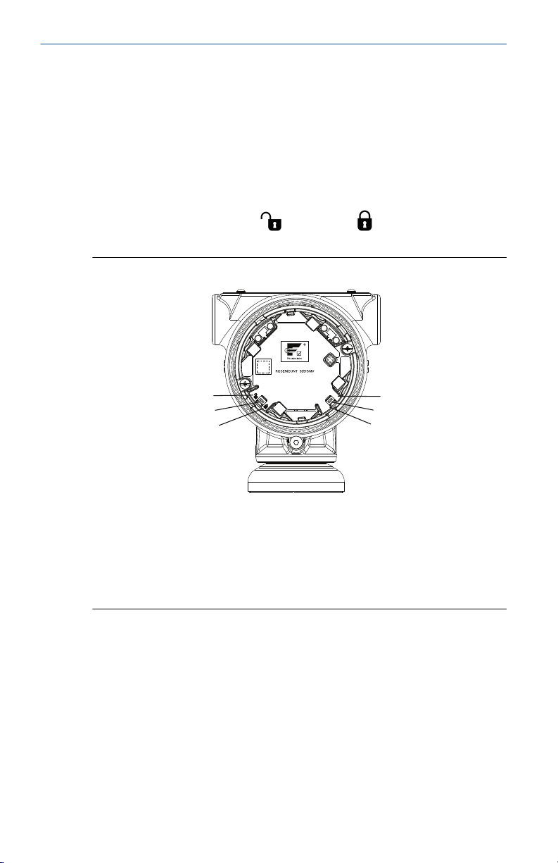
4 Set the switches
Prerequisites
Set Simulate and Security switch position before installation (location of
switches shown in Figure 4-1), as desired.
• The Simulate switch enables or disables the ability to set simulated alerts
or simulated measured value and status.
• The Security switch allows (
) or prevents ( ) any configuration of
the transmitter.
Figure 4-1: Simulate and Security Switches
A. Security unlocked position
B. Security switch
C. Security locked position
D. Simulate disabled position
E. Simulate switch
F. Simulate enabled position
Further security settings are available in the software, including settings
which use a software lock. Additionally, these settings can be used to disable
both hardware and software locks.
Use the following procedure to change the switch configuration:
Procedure
1. If the transmitter is installed, secure the segment, and remove
power.
14 Rosemount 3051SMV

October 2021 Quick Start Guide
2.
WARNING
Explosions could result in death or serious injury.
Do not remove the housing covers in explosive atmospheres when
the circuit is live.
Remove the housing cover opposite the field terminal side.
3. Slide the security and simulate switches into the preferred position.
4. Reinstall the housing cover and tighten so the cover is fully seated
with metal to metal contact between the housing and cover in order
to meet explosion proof requirements.
5. If the transmitter was installed, reapply power.
Quick Start Guide 15

DP
C
C
D
E
B
A
Quick Start Guide October 2021
5 Wiring, grounding, and power
Use a copper wire of sufficient size to ensure the voltage across the
transmitter power terminals does not drop below 9 Vdc. Power supply
voltage can be variable, especially under abnormal conditions such as when
operating on battery backup. A minimum of 12 Vdc under normal operating
conditions is recommended. Shielded twisted pair Type A cable is
recommended.
Figure 5-1: Wiring Terminals with RTD
A. Protective grounding terminal (do not ground cable shield at the
transmitter)
B. Trim shield and insulate
C. Minimize distance
D. Insulate shield
E. Connect shield back to the power supply ground
16 Rosemount 3051SMV

DP
B
A
D
C
C
E
October 2021 Quick Start Guide
Figure 5-2: Wiring Terminals without RTD
A. Protective grounding terminal (do not ground cable shield at the
transmitter)
B. Trim shield and insulate
C. Minimize distance
D. Insulate shield
E. Connect shield back to the power supply ground
Note
The power terminals are polarity insensitive, which means the electrical
polarity of the power leads does not matter when connecting to the power
terminals. If polarity sensitive devices are connected to the segment,
terminal polarity should be followed.
5.1
Signal wiring and shield grounding
Do not run signal wiring in conduit or open trays with power wiring, or near
heavy electrical equipment. Grounding terminations are provided on the
outside of the electronics housing and inside the terminal compartment.
These grounds are used when transient protection terminal blocks are
installed or to fulfill local regulations.
Procedure
1. Remove the field terminals housing cover.
2. To power the transmitter, connect the power leads to the terminals
indicated on the terminal block label.
3. Tighten the terminal screws to ensure adequate contact.
4. Trim the cable shield as short as practical and insulate from touching
the transmitter housing as indicated in Figure 5-1 and Figure 5-2.
Quick Start Guide 17

Quick Start Guide October 2021
Note
Do NOT ground the cable shield at the transmitter; if the cable shield
touches the transmitter housing, it can create ground loops and
interfere with communications. To protect the fieldbus segment
from noise, grounding techniques for shield wire require a single
grounding point for shield wire to avoid creating a ground loop.
a) Ensure the cable shield maintains a continuous connection to
the power supply ground.
b) Connect the cable shields for the entire segment to a single
good earth ground at the power supply.
Note
Improper grounding is the most frequent cause of poor
segment communications.
5. Reinstall the housing cover and tighten so the cover is fully seated
with metal to metal contact between the housing and cover in order
to meet explosion proof requirements.
6. Plug and seal unused conduit connections.
NOTICE
When the enclosed threaded plug is utilized in the conduit opening,
it must be installed with a minimum thread engagement in order to
comply with explosion-proof requirements. For straight threads, a
minimum of seven threads must be engaged. For tapered threads, a
minimum of five threads must be engaged.
5.2
5.3
18 Rosemount 3051SMV
Power supply
The transmitter requires between 9 and 32 Vdc (9 and 30 Vdc for intrinsic
safety, and 9 and 17.5 Vdc for FISCO intrinsic safety) to operate and provide
complete functionality.
Power conditioner
A fieldbus segment requires a power conditioner to isolate the power
supply, filter, and decouple the segment from other segments attached to
the same power supply.

October 2021 Quick Start Guide
5.4 Grounding
Signal wiring of the fieldbus segment can not be grounded. Grounding one
of the signal wires will shut down the entire fieldbus segment.
5.5 Signal termination
A terminator should be installed at the beginning and end of every fieldbus
segment.
5.6 Install optional process temperature input (Pt 100 RTD Sensor)
Note
To meet ATEX/IECEx Flameproof certification, only ATEX/IECEx Flameproof
cables (temperature input code C30, C32, C33, or C34) may be used.
Procedure
1. Mount the Pt 100 RTD Sensor in the appropriate location.
Use shielded four-wire cable for the process temperature
connection.
2. Connect the RTD cable to the Rosemount 3051S MultiVariable
Transmitter by inserting the cable wires through the unused housing
conduit and connect to the four screws on the transmitter terminal
block. An appropriate cable gland should be used to seal the conduit
opening around the cable.
3. Connect the RTD cable shield wire to the ground lug in the housing.
Quick Start Guide 19

C
B
Red
Red
White
White
A
Quick Start Guide October 2021
Figure 5-3: Transmitter RTD Wiring Connection
A. Ground lug
B. RTD cable assembly wires
C. Pt 100 RTD sensor
20 Rosemount 3051SMV

October 2021 Quick Start Guide
6 System readiness
6.1 System readiness
Confirm correct device driver
• Verify the correct device driver (DD) is loaded on your systems to ensure
proper communications.
• Download the correct device driver at your host vendor download site,
Emerson.com/Rosemount by selecting Support → Software Downloads
& Drivers or FieldCommGroup.org.
Quick Start Guide 21

Quick Start Guide October 2021
7 Zero trim the transmitter
Transmitters are shipped fully calibrated per request or by the factory
default of full scale.
A zero trim is a single-point adjustment used for compensating mounting
position and line pressure effects. Use the steps below if zero offset is less
than five percent of URL.
Procedure
1. When performing a zero trim, ensure the equalizing valve is open and
all wet legs are filled to the correct level. Make sure the transmitter is
connected to the host system.
2. Zero the differential pressure sensor by using the “Zero Differential
Pressure” method in the host system.
3. Follow the zero DP trim procedure.
4. Zero the static pressure sensor by using the “Zero Static Pressure” or
the “Lower Static Pressure Trim” method in the host system.
a) Use the “Zero Static Pressure” for a transmitter equipped with
a gage static pressure sensor and the “Lower Static Pressure
Trim” for a transmitter equipped with an absolute static
pressure sensor.
Note
When performing a lower sensor trim on a pressure sensor, it is
possible to degrade the performance of the sensor if inaccurate
calibration equipment is used. Use calibration equipment that is at
least three times as accurate as the pressure sensor of the
Rosemount 3051SMV FOUNDATION Fieldbus Transmitter.
5. Follow the static pressure trim procedure.
22 Rosemount 3051SMV

October 2021 Quick Start Guide
8 Product certifications
8.1 Rosemount 3051SMV/3051SFx
Rev 2.12
European directive information
A copy of the EC Declaration of Conformity can be found at the end of the
Quick Start Guide. The most recent revision of the EC Declaration of
Conformity can be found at Emerson.com/Rosemount.
Ordinary location certification
As standard, the transmitter has been examined and tested to determine
that the design meets the basic electrical, mechanical, and fire protection
requirements by a nationally recognized test laboratory (NRTL) as accredited
by the Federal Occupational Safety and Health Administration (OSHA).
Installing Equipment in North America
The US National Electrical Code (NEC) and the Canadian Electrical Code
(CEC) permit the use of Division marked equipment in Zones and Zone
marked equipment in Divisions. The markings must be suitable for the area
classification, gas, and temperature class. This information is clearly defined
in the respective codes.
8.1.1 USA E5 US Explosionproof (XP) and Dust-Ignitionproof (DIP)
Certificate
Standards
Markings
FM16US0089X
FM Class 3600 – 2011, FM Class 3615 – 2006, FM Class 3616 –
2011, FM Class 3810 – 2005, ANSI/NEMA 250 – 2003
XP CL I, DIV 1, GP B, C, D; T5; DIP CL II, DIV 1, GP E, F, G; CL III;
T5(–50 °C ≤ Ta ≤ +85 °C); Factory Sealed; Type 4X
I5 US Intrinsically Safe (IS) and Nonincendive (NI)
Certificate
Standards
Markings
Quick Start Guide 23
FM16US0233
FM Class 3600 –2011, FM Class 3610 – 2007, FM Class 3611 –
2004, FM Class 3616 – 2006, FM Class 3810 – 2005, NEMA
250 – 1991
IS CL I, DIV 1, GP A, B, C, D; CL II, DIV 1, GP E, F, G; Class III; Class
1, Zone 0 AEx ia IIC T4; NI CL 1, DIV 2, GP A, B, C, D; T4(–50 °C ≤
Ta ≤ +70 °C) when connected per Rosemount drawing
03151-1206; Type 4X

Quick Start Guide October 2021
Note
Transmitters marked with NI CL 1, DIV 2 can be installed in Division 2
locations using general Division 2 wiring methods or Nonincendive Field
Wiring (NIFW). See Drawing 03151-1206.
US Intrinsic Safety (IS) and Nonincendive (NI)
Certificate:
Standards:
Markings:
1143113
FM Class 3600:2011, FM Class 3610:2010, FM Class
3611:2004, FM Class 3810:2005, UL50E (1st Ed.)
IS Class I/II/III, Division 1, Groups A, B, C, D, T4/ E, F, and G
T135 °C; Class I, Zone 0 AEx ia IIC T4 Ga;
T4 (-50 °C ≤ Ta ≤ +70 °C) [HART];
T4 (-50 °C ≤ Ta ≤ +60 °C) [Fieldbus];
when connected per Rosemount drawing 03151-1207; Type
4X
IE US FISCO Intrinsically Safe
Certificate
Standards
Markings
US FISCO Intrinsically Safe
Certificate:
Standards:
Markings:
FM16US0233
FM Class 3600 – 2011, FM Class 3610 – 2010, FM Class 3611 –
2004, FM Class 3616 – 2006, FM Class 3810 – 2005, NEMA
250 – 1991
IS CL I, DIV 1, GP A, B, C, D; T4(–50 °C ≤ Ta ≤ +70 °C); when
connected per Rosemount drawing 03151-1006; Type 4X
1143113
FM Class 3600:2011, FM Class 3610:2010, FM Class
3611:2004, FM Class 3810:2005, UL50E (1st Ed.)
IS Class I/II/III, Division 1, Groups A, B, C, D, T4/ E, F, and G
T135 °C; Class I, Zone 0 AEx ia IIC T4 Ga;
T4 (-50 °C ≤ Ta ≤ +70 °C) [HART];
T4 (-50 °C ≤ Ta ≤ +60 °C) [Fieldbus];
when connected per Rosemount drawing 03151-1207; Type
4X
8.1.2 Canada E6 Canada Explosionproof, Dust Ignition-proof, Division 2
Certificate
24 Rosemount 3051SMV
1143113

October 2021 Quick Start Guide
Standards
Markings
CAN/CSA C22.2 No. 0-10, CSA Std C22.2 No. 25-1966, CSA
Std C22.2 No. 30-M1986, CSA C22.2 No. 94.2-07 , CSA Std
C22.2 No. 213-M1987, CAN/CSA C22.2 60079-11:14, CAN/
CSA-C22.2 No. 61010-1-12, ANSI/ISA 12.27.01-2003, CSA Std
C22.2 No. 60529:05 (R2010)
Explosionproof Class I, Division 1, Groups B, C, D; DustIgnitionproof Class II, Division 1, Groups E, F, G; Class III;
suitable for Class I, Division 2, Groups A, B, C, D; Type 4X
I6 Canada Intrinsically Safe
Certificate
Standards
Markings
1143113
CAN/CSA C22.2 No. 0-10, CSA Std C22.2 No. 25-1966, CSA
Std C22.2 No. 30-M1986, CSA C22.2 No. 94.2-07 , CSA Std
C22.2 No. 213-M1987, CAN/CSA C22.2 60079-11:14, CAN/
CSA-C22.2 No. 61010-1-12, ANSI/ISA 12.27.01-2003, CSA Std
C22.2 No. 60529:05 (R2010)
Intrinsically Safe Class I, Division 1; Groups A, B, C, D; suitable
for Class 1, Zone 0, IIC, T3C, Ta = 70 °C; when connected per
Rosemount drawing 03151-1207; Type 4X
IF Canada FISCO Intrinsically Safe
Certificate
Standards
Markings
1143113
CAN/CSA C22.2 No. 0-10, CSA Std C22.2 No. 25-1966, CSA
Std C22.2 No. 30-M1986, CSA C22.2 No. 94.2-07 , CSA Std
C22.2 No. 213-M1987, CAN/CSA C22.2 60079-11:14, CAN/
CSA-C22.2 No. 61010-1-12, ANSI/ISA 12.27.01-2003, CSA Std
C22.2 No. 60529:05 (R2010)
FISCO Intrinsically Safe Class I, Division 1; Groups A, B, C, D;
suitable for Class I, Zone 0; T3C, Ta = 70 °C; when installed per
Rosemount drawing 03151-1207; Type 4X
8.1.3 Europe E1 ATEX Flameproof
Certificate
Standards
Markings
Quick Start Guide 25
KEMA 00ATEX2143X
EN 60079-0:2012+A11:2013, EN 60079-1: 2014, EN
60079-26:2015
Ex II 1/2 G Ex db IIC T6…T4 Ga/Gb, T6(–60 °C ≤ Ta ≤ +70 °C),
T5/T4(–60 °C ≤ Ta ≤ +80 °C)

Quick Start Guide October 2021
Temperature class Process temperature
T6 –60 °C to +70 °C
T5 –60 °C to +80 °C
T4 –60 °C to +120 °C
Special Conditions for Safe Use (X):
1. This device contains a thin wall diaphragm less than 1 mm thickness
that forms a boundary between Category 1 (process connection) and
Category 2 (all other parts of the equipment). The model code and
datasheet are to be consulted for details of the diaphragm material.
Installation, maintenance, and use shall take into account the
environmental conditions to which the diaphragm will be subjected.
The manufacturer's instructions for installation and maintenance
shall be followed in detail to assure safety during its expected
lifetime.
2. Flameproof joints are not intended for repair.
3. Non-standard paint options may cause risk from electrostatic
discharge. Avoid installations that could cause electrostatic build-up
on painted surfaces, and only clean the painted surfaces with a damp
cloth. If paint is ordered through a special option code, contact the
manufacturer for more information.
4. Appropriate cable, glands, and plugs need to be suitable for a
temperature of 5 °C greater than maximum specified temperature
for location where installed.
I1 ATEX Intrinsic Safety
Certificate
Standards
Markings
Parameter HART®FOUNDATION
Voltage Ui30 V 30 V 7.14 V 30 V 30 V
Current Ii300mA300 mA 300 mA 2.31 mA 18.24 mA
Power P
i
Capacitance
C
i
26 Rosemount 3051SMV
Baseefa08ATEX0064X
EN 60079-0:2012, EN 60079-11:2012
Ex II 1 G Ex ia IIC T4 Ga, T4(–60 °C ≤Ta ≤ +70 °C)
™
Fieldbus
1 W 1.3 W 887 mW 17.32 mW 137 mW
14.8 nF 0 0.11 μF 0 0.8 nF
SuperModule
only
™
RTD (for 3051SFx)
HART Fieldbus

October 2021 Quick Start Guide
Parameter HART®FOUNDATION
Inductance
L
i
0 0 0 0 1.33 mH
Fieldbus
™
SuperModule
only
™
RTD (for 3051SFx)
HART Fieldbus
Special Conditions for Safe Use (X):
1. If the equipment is fitted with the optional 90 V transient suppressor,
it is incapable of withstanding the 500 V isolation from earth test and
this must be taken into account during installation.
2. The enclosure may be made of aluminum alloy and given a protective
polyurethane paint finish; however, care should be taken to protect it
from impact or abrasion if located in a Zone 0 environment.
IA ATEX FISCO
Certificate
Standards
Markings
Parameter FISCO
Voltage U
Current I
Power P
Capacitance C
Inductance L
i
i
Baseefa08ATEX0064X
EN 60079-0:2012, EN 60079-11:2012
Ex II 1 G Ex ia IIC T4 Ga, T4(–60 °C ≤Ta ≤ +70 °C)
i
i
i
17.5 V
380 mA
5.32 W
0
0
ND ATEX Dust
Certificate
Standards
Markings
Special Conditions for Safe Use (X):
1. Cable entries must be used which maintain the ingress protection of
2. Unused cable entries must be filled with suitable blanking plugs
Quick Start Guide 27
BAS01ATEX1374X
EN 60079-0:2012+A11:2013, EN 60079-31:2009
Ex II 1 D Ex ta IIIC T105 °C T
V
= 42.4 V
max
95 °C Da, (–20 °C ≤Ta ≤ +85 °C),
500
the enclosure to at least IP66.
which maintain the ingress protection of the enclosure to at least
IP66.

Quick Start Guide October 2021
3. Cable entries and blanking plugs must be suitable for the ambient
temperature range of the apparatus and capable of withstanding a 7J
impact test.
4. The SuperModule(s) must be securely screwed in place to maintain
the ingress protection of the enclosure(s).
N1 ATEX Type n
Certificate
Standards
Markings
Special Condition for Safe Use (X):
1. If fitted with a 90 V transient suppressor, the equipment is not
capable of withstanding the 500 V electrical strength test as defined
in Clause 6.5.1 of EN 60079-15:2010. This must be taken into
account during installation.
8.1.4 International E7 IECEx Flameproof and Dust
Certificate
Standards
Markings
Temperature class Process temperature
T6 –60 °C to +70 °C
T5 –60 °C to +80 °C
T4 –60 °C to +120 °C
Baseefa08ATEX0065X
EN 60079-0:2012, EN 60079-15:2010
Ex II 3 G Ex nA IIC T4 Gc, (–40 °C ≤Ta ≤ 70 °C), V
max
= 45 V
IECEx KEM 08.0010X (Flameproof)
IEC 60079-0:2011, IEC 60079-1:2014,IEC 60079-26:2014
Ex db IIC T6…T4 Ga/Gb, T6(–60 °C≤ Ta ≤ +70 °C), T5/T4(–60 °C
≤ Ta ≤ +80 °C)
Special Conditions for Safe Use (X):
1. This device contains a thin wall diaphragm less than 1 mm thickness
that forms a boundary between EPL Ga (process connection) and EPL
Gb (all other parts of the equipment). The model code and datasheet
are to be consulted for details of the diaphragm material.
Installation, maintenance and use shall take into account the
environmental conditions to which the diaphragm will be subjected.
The manufacturer's instructions for installation and maintenance
shall be followed in detail to assure safety during its expected
lifetime.
2. Flameproof joints are not intended for repair.
28 Rosemount 3051SMV

October 2021 Quick Start Guide
3. Non-standard paint options may cause risk from electrostatic
discharge. Avoid installations that could cause electrostatic build-up
on painted surfaces, and only clean the painted surfaces with a damp
cloth. If paint is ordered through a special option code, contact the
manufacturer for more information.
4. Appropriate cable, glands and plugs need to be suitable for a
temperature of 5 °C greater than maximum specified temperature
for location where installed.
Certificate
Standards
Markings
IECEx BAS 09.0014X (Dust)
IEC 60079-0:2011, IEC 60079-31:2008
Ex ta IIIC T105 °C T
95 °C Da, (–20 °C ≤ Ta ≤ +85 °C), Vmax =
500
42.4 V
Special Conditions for Safe Use (X):
1. Cable entries must be used which maintain the ingress protection of
the enclosure to at least IP66.
2. Unused cable entries must be filled with suitable blanking plugs
which maintain the ingress protection of the enclosure to at least
IP66.
3. Cable entries and blanking plugs must be suitable for the ambient
temperature range of the apparatus and capable of withstanding a 7J
impact test.
4. The Rosemount 3051S SuperModule™ must be securely screwed in
place to maintain the ingress protection of the enclosure.
I7 IECEx Intrinsic Safety
Certificate
Standards
Markings
Parameter HART
Voltage Ui30 V 30 V 7.14 V 30 V 30 V
Current I
Power P
Capacitance
C
i
i
i
IECEx BAS 08.0025X
IEC 60079-0:2011, IEC 60079-11:2011
Ex ia IIC T4 Ga, T4(–60 °C ≤ Ta ≤ +70 °C)
®
FOUNDATION
Fieldbus
300 mA 300 mA 300 mA 2.31 mA 18.24 mA
1 W 1.3 W 887 mW 17.32
14.8 nF 0 0.11 μF 0 0.8 nF
™
SuperModule
only
™
RTD (for 3051SFx)
HART Fieldbus
mW
137 mW
Quick Start Guide 29

Quick Start Guide October 2021
Parameter HART
Inductance
L
i
0 0 0 0 1.33 mH
®
FOUNDATION
Fieldbus
™
SuperModule
only
™
RTD (for 3051SFx)
HART Fieldbus
Special Conditions for Safe Use (X):
1. If the equipment is fitted with the optional 90 V transient suppressor,
it is incapable of withstanding the 500 V isolation from earth test and
this must be taken into account during installation.
2. The enclosure may be made of aluminum alloy and given a protective
polyurethane paint finish; however, care should be taken to protect it
from impact or abrasion if located in a Zone 0 environment.
I7 IECEx Intrinsic Safety - Group 1 - Mining (I7 with Special A0259)
Certificate
Standards
Markings
Safety parameter HART
Voltage U
Current I
Power P
Capacitance C
Inductance L
i
i
i
IECEx TSA 20.0015X
IEC 60079-0: 2017, IEC 60079-11: 2011
Ex ia I Ma (-60 °C ≤ Ta ≤ +70 °C)
®
30 V Voltage U
300 mA Current I
1 W Power P
14.8 nF Capacitance C
i
i
0 Inductance L
Safety parameter RTD (HART)
o
o
o
30 V
2.31 mA
17.32 mW
33 nF
o
3.33 H
o
Note
This must be sourced from a resistively limited power supply.
Specific Condition of Use (X):
1. If the apparatus is fitted with optional 90 V transient suppressor, it is
not capable of withstanding the 500 Vac insulation test required by
Clause 6.3.13 of IEC60079-11. This must be taken into account when
installing the apparatus.
IG IECEx FISCO
Certificate
Standards
Markings
30 Rosemount 3051SMV
IECEx BAS 08.0025X
IEC 60079-0:2011, IEC 60079-11:2011
Ex ia IIC T4 Ga, T4(–60 °C≤ Ta ≤ +70 °C)

October 2021 Quick Start Guide
Parameter FISCO
Voltage U
Current I
Power P
Capacitance C
Inductance L
i
i
i
i
i
17.5 V
380 mA
5.32 W
0
0
N7 IECEx Type n
Certificate
Standards
Markings
Special Condition for Safe Use (X):
8.1.5 Brazil E2 Brazil Flameproof
Certificate
Standards
Markings
Temperature class Ambient temperature Process connection
T6 -60 °C to +70 °C –60 °C to +70 °C
T5 -60 °C to +80 °C –60 °C to +80 °C
T4 -60 °C to +80 °C –60 °C to +120 °C
IECEx BAS 08.0026X
IEC 60079-0:2011, IEC 60079-15:2010
Ex nA IIC T5 Gc,(–40 °C ≤Ta ≤ 70 °C)
1. If fitted with a 90 V transient suppressor, the equipment is not
capable of withstanding the 500 V electrical strength test as defined
in Clause 6.5.1 of IEC 60079-15:2010. This must be taken into
account during installation.
UL-BR 15.0393X
ABNT NBR IEC 60079-0:2013, ABNT NBR IEC 60079-1:2016,
ABNT NBR IEC 60079-26:2016
Ex db IIC T6...T4 Ga/Gb, T6(–60 °C ≤ Ta ≤ +70 °C), T5/T4 (–60
°C ≤ Ta ≤ +80 °C), IP66
temperature
Special Conditions for Safe Use (X):
1. The device contains a thin wall diaphragm less than 1 mm thick that
forms a boundary between zone 0 (process connection) and zone 1
(all other parts of the equipment). The model code and datasheet are
to be consulted for details of the diaphragm material. Installation,
maintenance, and use shall take into account the environmental
Quick Start Guide 31

Quick Start Guide October 2021
conditions to which the diaphragm will be subjected. The
manufacturer’s instructions for maintenance shall be followed in
detail to assure safety during its expected lifetime.
2. Flameproof joints are not intended for repair.
3. Non-standard paint options may cause risk from electrostatic
discharge. Avoid installations that could cause electrostatic build-up
on painted surfaces, and only clean the painted surfaces with a damp
cloth. If paint is ordered through a special option code, contact the
manufacturer for more information.
I2 Brazil Intrinsic Safety
Certificate
Standards
UL-BR 15.0357X
ABNT NBR IEC 60079-0:2008 + Addendum 1:2011, ABNT NBR
IEC 60079-11:2009
Markings
Ex ia IIC T4 Ga (–60 °C ≤ Ta ≤ +70 °C)
Special Conditions for Safe Use (X):
1. If the equipment is fitted with the optional 90 V transient suppressor,
it is incapable of withstanding the 500 V isolation from earth test and
this must be taken into account during installation.
2. The enclosure may be made of aluminium alloy and given a
protective polyurethane paint finish; however, care should be taken
to protect it from impact or abrasion if located in a Zone 0
environment, areas requiring EPL Ga.
Parameter
Voltage U
Current I
Power P
Capacitance Ci14.8 nF 0 0 0.8 nF
Inductance Li0 0 0 1.33 mH
i
i
i
®
HART
Input RTD Input RTD
30 V 30 V 30 V 30 V
300 mA 2.31 mA 300 mA 18.24 mA
1 W 17.32 mW 1.3 W 137 mW
Fieldbus
8.1.6 China E3 China Flameproof and Dust Ignition-proof
Certificate
32 Rosemount 3051SMV
3051SMV: GYJ18.1550X [Mfg USA, China, Singapore]
3051SFx: GYJ21.3300X [Mfg USA, China, Singapore]

October 2021 Quick Start Guide
Standards
3051SMV: GB3836.1-2010, GB3836.2-2010,
GB3836.20-2010
3051SFx: GB3836.1-2010, GB3836.2-2010, GB12476.1-2013,
GB12476.5-2013
Markings
3051SMV: Ex d IIC T6~T4 Ga/Gb
3051SFx: Ex d IIC T4~T6 Ga/Gb; Ex tD T 105 °C T
95 °C; IP66
500
Special Conditions for Safe Use (X):
一、产品安全使用特殊条件
证书编号后缀“X”表明产品具有安全使用特殊条件:
1. 涉及隔爆接合面的维修须联系产品制造商。
2. 产品使用厚度小于 1 mm 的隔膜作为 0 区(过程连接)和 1 区(产
品其他部分)的隔离,安装和维护时需严格遵守制造商提供的说明
书,以确保安全性。
3. 产品外部涂层可能产生静电危险,使用时须防止产生静电火花,只
能用湿布清理。
二、产品使用注意事项
1. 产品温度组别和使用环境温度之间的关系为:
温度组别 使用环境温度 过程温度
T6 -60 °C to +70 °C –60 °C to +70 °C
T5 -60 °C to +80 °C –60 °C to +80 °C
T4 -60 °C to +80 °C –60 °C to +120 °C
2. 用于爆炸性粉尘环境中,产品使用环境温度为:-20 ℃ ≤ Ta ≤+ 85
℃。
3. 产品外壳设有接地端子,用户在使用时应可靠接地。
4. 安装现场应不存在对产品外壳有腐蚀作用的有害气体。
5. 现场安装时,电缆引入口须选用经国家指定的防爆检验机构检验认
可、具有 Ex dⅡC Gb, Ex tD A20 IP66 防爆等级的电缆引入装置或堵封
件,冗余电缆引入口须用堵封件有效密封。
6. 用于爆炸性气体环境中,现场安装、使用和维护必须严格遵守“严禁
带电开盖!”的警告语。
7. 用于爆炸性粉尘环境中,产品外壳表面需保持清洁,以防粉尘堆
积,但严禁用压缩空气吹扫。
Quick Start Guide 33

Quick Start Guide October 2021
8. 用户不得自行更换该产品的零部件,应会同产品制造商共同解决运
行中出现的故障,以杜绝损坏现象的发生。
9. 产品的安装、使用和维护应同时遵守产品使用说明书、
GB3836.13-2013“爆炸性环境 第 13 部分:设备的修理、检修、修
复和改造”、GB/T3836.15-2017“爆炸性环境 第 15 部分:电气装置
的设计、选型和安装”、GB/T3836.16-2017“爆炸性环境 第 16 部
分:电气装置的检查与维护”和 GB50257-2014“电气装置安装工程
爆炸和火灾危险环境电力装置施工及验收规范”和 GB15577-2007
“粉尘防爆安全规程”、GB12476.2-2010“可燃性粉尘环境用电气设
备 第 2 部分:选型和安装”的有关规定。
I3 China Intrinsic Safety
Certificate
3051SMV: GYJ18.1551X [Mfg USA, China, Singapore]
3051SFx: GYJ21.3301X [Mfg USA, China, Singapore]
Standards
3051SMV: GB3836.1-2010, GB3836.4-2010,
GB3836.20-2010
3051SFx: GB3836.1-2010, GB3836.4-2010, GB3836.20-2010
Markings
3051SMV: Ex ia IIC T4 Ga
3051SFx: Ex ia IIC T4 Ga,
c 输出代码 防爆标志
A, F Ex iaⅡC T4 Ga,Ex tD A20 IP66
X Ex iaⅡC T4 Ga
T105 ℃ T500 95 ℃
一、 产品安全使用特殊条件
产品防爆合格证号后缀“X”代表产品安全使用有特殊条件:
1. 产品外壳含有轻金属,用于 0 区时需注意防止由于冲击或摩擦产生
的点燃危险。
2. 此设备不能承受 GB3836.4-2010 标准中第 6.3.12 条规定的 500V 交
流有效值试验电压的介电强度试验。
3. c 为 X 时,天线表面电阻大于 1 GΩ,为了避免静电积聚,不允许用
溶剂或者干布擦拭;电源模块表面电阻大于 1 GΩ,如果在危险区域
更换,则需要避免静电积聚;只能使用由原制造厂提供的 P/N
753-9220-XXXX 电池。
二、产品使用注意事项
1. 用于爆炸性气体环境中,产品使用环境温度为:-60 ℃ ≤ Ta ≤+ 70
℃ 用于爆炸性粉尘环境中,产品使用环境温度为:-20 ℃ ≤ Ta ≤+
85 ℃
34 Rosemount 3051SMV

October 2021 Quick Start Guide
2. 本安电气参数:
c 输出代码端子 最高输
SuperMo
dule
A +, -, CAN 30 300 1 12 0
A 配
M7、M8
或 M9 显
示
F +, - 30 300 1.3 0 0
FISCO +, - 17.5 300 5.32 0 0
+, -, CAN 30 300 1 30 0
+, - 30 300 1 12 60
入电压
Ui (V)
最大输
入电流 I
(mA)
i
最大输
入功率
Pi (W)
最大内部 等效参数
Ci (nF) Li (μH)
d 代码为 A 时
最高输出
电压 U
(V)
RTD 30 2.31 17.32 0 0
SuperMod
ule
7.14 300 887 110 0
o
最大输出
电流 I
o
(mA)
最大输出
功率 P
o
(mW)
最大内部 等效参数
Ci (nF) Li (μH)
注: 本安电气参数符合 GB3836.19-2010 对 FISCO 现场仪表的参数要
求。
3. 选择 Remote Mount 选项 M7、M8、M9 时,电缆分布电容小于 24
nF,分布电感小于 60 μH。
4. 该产品必须与已通过防爆认证的关联设备配套共同组成本安防爆系
统方可使用于爆炸性气体环境。其系统接线必须同时遵守本产品和
所配关联设备的使用说明书要求,接线端子不得接错。
5. 用于爆炸性粉尘环境中,电缆引入口须选用国家指定的防爆检验机
构按检验认可、具有 Ex tD A20 IP66 防爆等级的电缆引入装置或堵
封件,冗余电缆引入口须用堵封件有效密封。
6. 用户不得自行更换该产品的零部件,应会同产品制造商共同解决运
行中出现的故障,以杜绝损坏现象的发生。
7. 产品的安装、使用和维护应同时遵守产品使用说明书、
GB3836.13-2013“爆炸性环境 第 13 部分:设备的修理、检修、修
复和改造”、GB/T3836.15-2017“爆炸性环境 第 15 部分:电气装置
的设计、选型和安装”、GB/T3836.16-2017“爆炸性环境 第 16 部
分:电气装置的检查与维护”、GB/T 3836.18-2017“爆炸性环境 第
18 部分:本质安全电气系统”、GB50257-2014“电气装置安装工程
Quick Start Guide 35

Quick Start Guide October 2021
爆炸和火灾危险环境电力装置施工及验收规范” GB12476.2-2010“可
燃性粉尘环境用电气设备 第 2 部分:选型和安装”的有关规定。
8.1.7 Technical Regulation Custom Union (EAC) EM EAC Flameproof and Dust Ignition-proof
Certificate
Markings
IM Technical Regulation Customs Union (EAC) Intrinsic Safety
Certificate
Markings
8.1.8 Japan E4 Japan Flameproof
Certificate
Markings
Temperatu
re class
T6 –60 to +70 °C –60 to +70 °C
T5 –60 to +80 °C –60 to +80 °C
T4 –60 to +80 °C –60 to +120 °C
Special Conditions for Safe Use (X):
1. This device contains a thin wall diaphragm less than 1 mm thickness
EAЭC RU C-US.AA87.B.00587/20
Ga/Gb Ex d IIC T6…T4 X
Ex tb IIIC T105 °C T
Ex ta IIIC T105 °C T
95 °C Db X
500
95 °C Da X
500
RU C-US.AA87.B.00378
0Ex ia IIC T4 Ga X
CML 17JPN1147X
Ex db IIC T6…T4 Ga/Gb
Ambient temperature Process temperature
that forms a boundary between EPL Ga (process connection) and EPL
Gb (all other parts of the equipment). The model code and datasheet
are to be consulted for details of the diaphragm material.
Installation, maintenance, and use shall consider the environmental
conditions to which the diaphragm will be subjected. The
manufacturer’s instructions for installation and maintenance shall be
followed in detail to assure safety during its expected lifetime.
2. Flameproof joints are not intended for repair.
3. Non-standard paint options may cause risk from electrostatic
discharge. Avoid installations that could cause electrostatic build-up
on painted surfaces, and only clean the painted surfaces with a damp
36 Rosemount 3051SMV

October 2021 Quick Start Guide
cloth. If paint is ordered through a special option code, contact the
manufacturer for more information.
8.1.9 Republic of Korea EP Republic of Korea Flameproof
Certificate
Markings
19-KA4BO-0913X [Mfg USA], 12-KB4BO-0180X [Mfg USA],
11-KB4BO-0068X [Mfg Singapore]
Ex d IIC T6...T4 Ga/Gb
IP Republic of Korea Intrinsic Safety [HART Only]
Certificate
Markings
10-KB4BO-0021X [Mfg SMMC], 16-KB4BO-0440X [Mfg USA],
19-KA4BO-0911X [Mfg USA]
Ex ia IIC T4
8.1.10 Combinations
K1
K2
K5
K6
K7
KA
KB
KC
KD
KM
KP
Combination of E1, I1, N1, and ND
Combination of E2 and I2
Combination of E5 and I5
Combination of E6 and I6
Combination of E7, I7, and N7
Combination of E1, I1, E6, and I6
Combination of E5, I5, E6, and I6
Combination of E1, I1, E5, and I5
Combination of E1, I1, E5, I5, E6, and I6
Combination of EM and IM
Combination of EP and IP
8.1.11 Additional certifications SBS American Bureau of Shipping (ABS) Type Approval
Certificate
Intended Use
17-RJ1679518-PDA
Measure gauge or absolute pressure of liquid, gas or vapor
applications on ABS classed vessels, marine, and offshore
installations. [HART only]
SBV Bureau Veritas (BV) Type Approval
Certificate
Quick Start Guide 37
31910 BV

Quick Start Guide October 2021
Requirements
Application
Bureau Veritas Rules for the Classification of Steel Ships
Class Notations: AUT-UMS, AUT-CCS, AUT-PORT and AUTIMS. [HART only]
SDN Det Norske Veritas (DNV) Type Approval
Certificate
Intended
Use
Application
TAA00000K9
Det Norske Veritas’ Rules for Classification of Ships, High
Speed and Light Craft, and Det Norske Veritas’ Offshore
Standards.[HART only]
Location classes
Type 3051S
Temperature D
Humidity B
Vibration A
EMC A
Enclosure D/IP66/IP68
SLL Lloyds Register (LR) Type Approval
Certificate
Application
LR21173788TA
Environmental categories ENV1, ENV2, ENV3, and ENV5.
[HART only]
38 Rosemount 3051SMV

October 2021 Quick Start Guide
8.2 Declaration of conformity
Quick Start Guide 39

Quick Start Guide October 2021
40 Rosemount 3051SMV

October 2021 Quick Start Guide
Quick Start Guide 41

Quick Start Guide October 2021
8.3 China RoHS
42 Rosemount 3051SMV

October 2021 Quick Start Guide
Quick Start Guide 43

*00825-0100-4853*
00825-0100-4853, Rev. AG
Quick Start Guide
October 2021
For more information:
©
2021 Emerson. All rights reserved.
Emerson Terms and Conditions of Sale are
available upon request. The Emerson logo
is a trademark and service mark of
Emerson Electric Co. Rosemount is a mark
of one of the Emerson family of
companies. All other marks are the
property of their respective owners.
www.emerson.com
Loading...