

Page 1

Quick Start Guide
00825-0100-4007, Rev DD
January 2017
Rosemount™ 3051 Pressure Transmitter
and Rosemount 3051CF Series Flowmeters
with 4–20 mA HART® Revision 5 and 7 Protocol
Note
Before installing the transmitter, confirm the correct device driver is loaded on the host systems.
See page 3 for system readiness.
Page 2

Quick Start Guide
January 2017
NOTICE
This guide provides basic guidelines for Rosemount 3051 Transmitters. It does not provide instructions for
configuration, diagnostics, maintenance, service, troubleshooting, Explosion-proof, Flameproof, or intrinsically
safe (I.S.) installations. Refer to the Rosemount 3051 HART Revision 5 and 7 Reference Manual
instruction. This manual is also available electronically on Emerson.com/Rosemount
Explosions could result in death or serious injury.
Installation of this transmitter in an explosive environment must be in accordance with the appropriate local,
national, and international standards, codes, and prac tices. Review the approvals section of the Rosemount
3051 Reference Manual
Before connecting a HART-based communicator in an explosive atmosphere, make sure the instruments in
the loop are installed in accordance with intrinsically safe or non-incendive field wiring practices.
In an Explosion-proof/Flameproof installation, do not remove the transmitter covers when power is applied
to the unit.
Process leaks may cause harm or result in death.
To avoid process leaks, only use the O-ring designed to seal with the corresponding flange adapter.
Electrical shock can result in death or serious injury.
Avoid contact with the leads and the terminals. High voltage that may be present on leads can cause
electrical shock.
Conduit/cable entries
Unless marked, the conduit/cable entries in the transmitter housing use a
Entries marked “M20” are M20 ⫻ 1.5 thread form. On devices with multiple conduit entries, all entries will
have the same thread form.
Only use plugs, adapters, glands, or conduit with a compatible thread form when closing these entries.
for any restrictions associated with a safe installation.
1
/2–14 NPT thread form.
for mor e
.
Contents
System readiness . . . . . . . . . . . . . . . . . . . . . . . . . 3
Transmitter installation . . . . . . . . . . . . . . . . . . . 4
Mount the transmitter . . . . . . . . . . . . . . . . . . . . 4
Consider housing rotation . . . . . . . . . . . . . . . . . 8
Set the switches . . . . . . . . . . . . . . . . . . . . . . . . . . 8
2
Connect the wiring and power up . . . . . . . . . . 9
Verify configuration . . . . . . . . . . . . . . . . . . . . . 11
Trim the transmitter . . . . . . . . . . . . . . . . . . . . . 14
Safety instrumented systems installation . . . 15
Product certifications . . . . . . . . . . . . . . . . . . . . 16
Page 3

January 2017
1.0 System readiness
1.1 Confirm HART Revision capability
If using HART based control or asset management systems, confirm the
HART capability of those systems prior to transmitter installation. Not all
systems are capable of communicating with HART Revision 7 protocol. This
transmitter can be configured for either HART Revision 5 or 7.
For instructions on how to change the HART revision of your transmitter, see
page 13.
Quick Start Guide
1.2 Confirm correct device driver
Device
revisi on
™
) is loaded on your systems to
Review
instructions
Manual document
(3)
number
00809-0100-4007
functionality
Changes to
software
See Footnote 4 for
list of changes.
Review
(4)
Verify the latest device driver (DD/DTM
ensure proper communications.
Download the latest device driver at Emerson.com or Hartcomm.org.
Rosemount 3051 device revisions and drivers
Table 1 provides the information necessary to ensure you have the correct
device driver and documentation for your device.
Table 1. Rosemount 3051 Device Revisions and Files
Identify device Find device driver
Software
release
date
Dec-11 1.0.0 01
Jan-98 N/A 178 5 3 00809-0100-4001 N/A
1. NAMUR sof tware revision is located on the hardwa re tag of the device. In ac cordan ce with NE53, revisio ns of the
least significant level X (of 1.0.X) do not change functionality or operation of the device and will not be reflected
in this device revision histor y.
2. HART software revision can be read using a HART capable configuration tool.
3. Device driver file names use device and DD revision, e.g. 10_01. HART protocol is designed to enable legacy
device driver revisions to continue to communicate with new HART devices. To access new functionality, the new
device driver must be downloaded. It is recommended to download new device driver files to ensure full
functionality.
4. HART Revision 5 and 7 Selectable, Power Diagnostics, Safety Certified, Local Operator Interface (LOI), Process
Alerts, Scaled Variable, Configurable Alarms, Expanded Engineering Units.
NAMUR
software
revision
(1)
HART
software
revision
(2)
HART
universal
revision
7 10
5 9
3
Page 4
Quick Start Guide
Flow
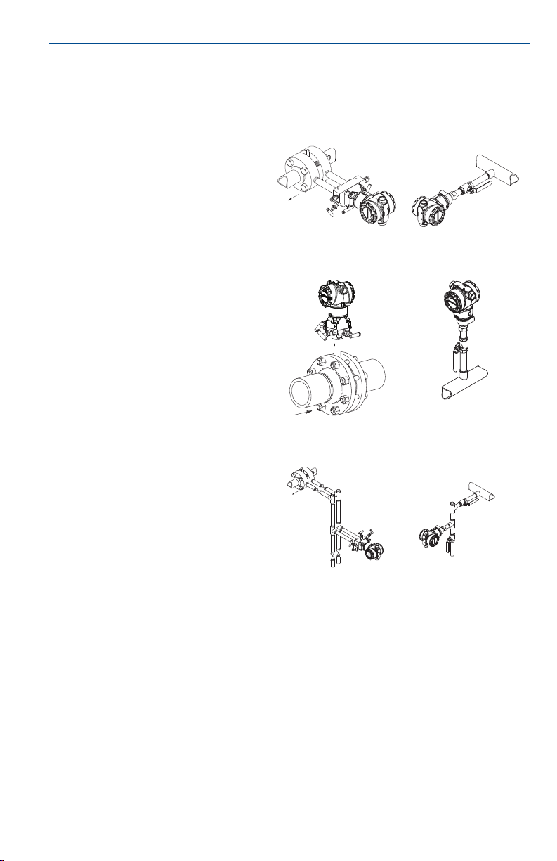
2.0 Transmitter installation
2.1 Mount the transmitter
Liquid applications
1. Place taps to the side of the
line.
2. Mount beside or below the
taps.
3. Mount the transmitter so
that the drain/vent valves
are oriented upward.
Gas applications
1. Place taps in the top or side
of the line.
2. Mount beside or above the
taps.
Flow
January 2017
Coplanar In-line
Steam applications
1. Place taps to the side of the
line.
2. Mount beside or below the
taps.
3. Fill impulse lines with
water.
4
Flow
Page 5
January 2017
Quick Start Guide
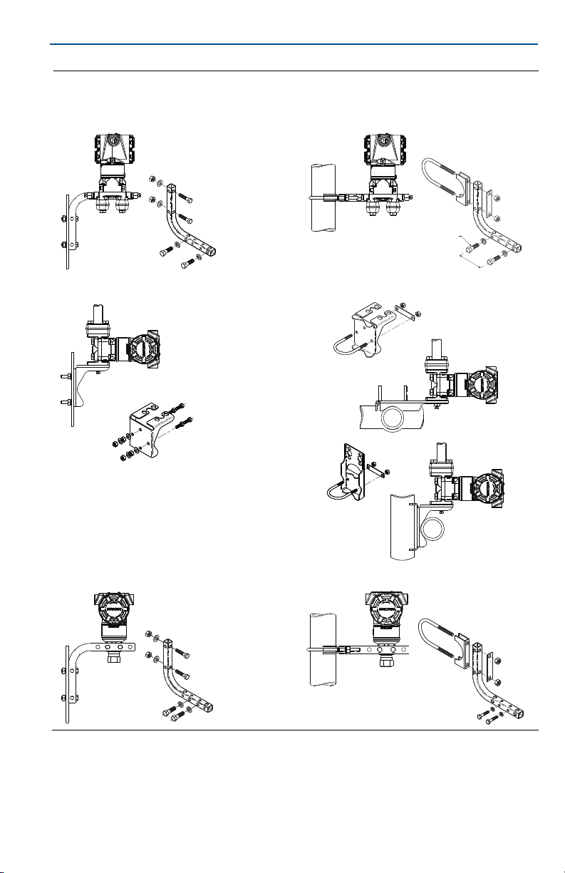
Figure 1. Panel and Pipe Mounting
Panel mount
(1)
Pipe mount
Coplanar flange
Traditional flange
1.5/16 ⫻ 11/2 panel bolts are customer supplied.
Rosemount 3051T
5
Page 6
Quick Start Guide
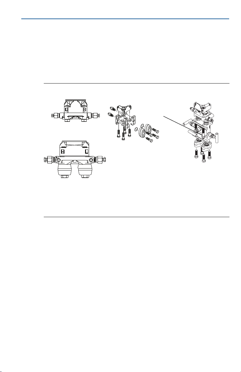
Bolting considerations
If the transmitter installation requires assembly of the process flanges,
manifolds, or flange adapters, follow the assembly guidelines to ensure a tight
seal for optimal performance characteristics of the transmitters. Use only bolts
supplied with the transmitter or sold by Emerson
page 6 illustrates common transmitter assemblies with the bolt length required
for proper transmitter assembly.
January 2017
™
as spare parts. Figure 2 on
Figure 2. Common Transmitter Assemblies
A
4 × 1.75-in. (44 mm)
B
4 × 2.88-in. (73 mm)
A. Transmitter with coplanar flange
B. Transmitter with coplanar flange and optional flange adapters
C. Transmitter with traditional flange and optional flange adapters
D. Transmitter with coplanar flange and optional manifold and flange adapters
C
4 × 1.75-in.
(44 mm)
4 × 2.25-in. (57 mm)
4 × 1.50-in.
(38 mm)
D
4 × 1.75-in. (44 mm)
Bolts are typically carbon steel or stainless steel. Confirm the material by
viewing the markings on the head of the bolt and referencing Table 2 on page 7.
If bolt material is not shown in Table 2, contact a local Emerson representative
for more information.
Use the following bolt installation procedure:
1. Carbon steel bolts do not require lubrication and the stainless steel bolts are
coated with a lubricant to ease installation. However, no additional lubricant
should be applied when installing either type of bolt.
2. Finger-tighten the bolts.
3. Torque the bolts to the initial torque value using a crossing pattern.
See Table 2 for initial torque value.
4. Torque the bolts to the final torque value using the same crossing pattern.
See Table 2 for final torque value.
5. Verify the flange bolts are protruding through the isolator plate before
applying pressure.
6
Page 7
January 2017
A
Table 2. Torque Values for the Flange and Flange Adapter Bolts
Quick Start Guide
Bolt material Head markings Initial torque Final torque
Carbon Steel (CS) 300 in-lb 650 in-lb
316
Stainle ss Steel (SST) 150 in-lb 300 in-lb
316
R
B8M
STM
316
B7M
316
316
SW
Environmental seal for housing
Thread sealing (PTFE) tape or paste on male threads of conduit is required to
provide a water/dust tight conduit seal and meets requirements of NEMA
Type 4X, IP66, and IP68. Consult factory if other ingress protection ratings are
required.
For M20 threads, install conduit plugs to full thread engagement or until
mechanical resistance is met.
®
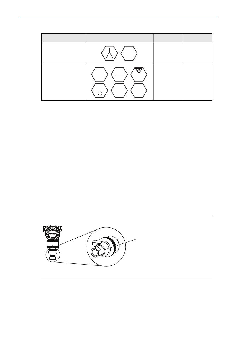
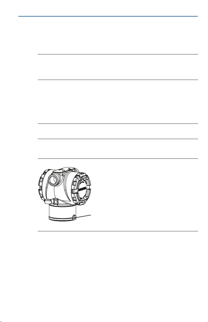
In-line gage transmitter orientation
The low side pressure port (atmospheric reference) on the in-line gage
transmitter is located in the neck of the transmitter, behind the housing. The
vent path is 360° around the transmitter between the housing and sensor.
(See Figure 3.)
Keep the vent path free of any obstruction, including but not limited to paint,
dust, and lubrication by mounting the transmitter so that the process can
drain away.
Figure 3. In-line Gage Low Side Pressure Port
A. Low side pressure port (atmospheric reference)
Installing high pressure coned and threaded connection
The transmitter comes with an autoclave connection designed for high
pressure applications. Follow the steps below to properly connect the
transmitter to your process:
1. Apply a process-compatible lubricant to the gland nut threads.
2. Slip the gland nut onto the tube, then thread the collar onto the tube end
(the collar is reverse threaded).
7
Page 8
Quick Start Guide
A
3. Apply a small amount of process-compatible lubricant applied to the tube
cone to help prevent galling and facilitate sealing. Insert the tubing into the
connection and tighten finger tight.
4. Tighten the gland nut to a torque of 25 ft-lb.
Note
A weep hole has been designed into the transmitter for safety and leak detection. If fluid
begins to leak from the weep hole, isolate the process pressure, disconnect the
transmitter, and reseal until the leak is resolved.
2.2 Consider housing rotation
To improve field access to wiring or to better view the optional LCD display:
1. Loosen the housing rotation set screw using a
2. Turn the housing left or right maximum up to 180° from its original
position.
Note
Over rotating can damage the transmitter.
3. Re-tighten the housing rotation set screw to no more than 7 in-lb when
desired location is reached.
Figure 4. Transmitter Housing Set Screw
(1)
5
/64-in. hex wrench.
January 2017
A. Housing rotation set screw (5/64-in.)
2.3 Set the switches
Set alarm and security switch configuration before installation as shown in
Figure 5.
The alarm switch sets the analog output alarm to high or low.
- Default alarm is high.
The security switch allows (unlocked symbol) or prevents (locked symbol)
any configuration of the transmitter.
- Default security is off (unlocked symbol).
1. Rosemount 3051C original position aligns with “H” side; Rosemount 3051T original position is the opposite side of
bracket holes.
8
Page 9
January 2017
Use the following procedure to change the switch configuration:
1. If the transmitter is installed, secure the loop, and remove power.
2. Remove the housing cover opposite the field terminal side. Do not remove
3. Slide the security and alarm switches into the preferred position using a small
4. Reattach the transmitter cover. The cover must be fully engaged to comply
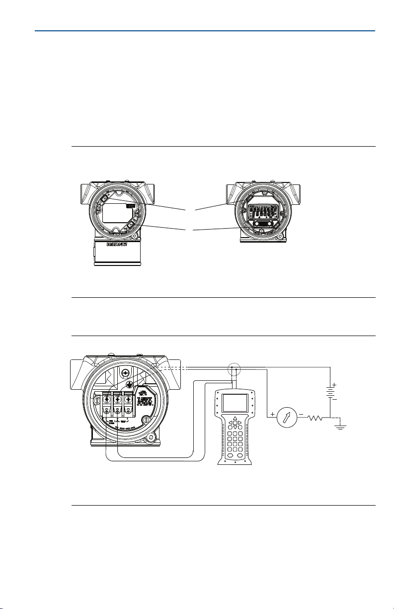
Figure 5. Transmitter Electronics Board
A. Alarm
B. Security
Quick Start Guide
the instrument cover in explosive atmospheres when the circuit is live.
screwdriver.
with explosion-proof requirements.
Without LCD display With LOI or LCD display
A
B
2.4 Connect the wiring and power up
Figure 6. Transmitter Wiring Diagrams (4–20 mA)
A. 24 Vdc supply
B. R
≥ 250
L
C. Current meter (optional)
Shielded twisted pair cable should be used for best results. Use 24 AWG or larger
wire that does not exceed 5,000 feet (1500 meters) in length. If applicable,
install wiring with a drip loop. Arrange the drip loop so the bottom is lower than
the conduit connections and the transmitter housing.
A
B
C
9
Page 10
Quick Start Guide
DP
A
B
C
A
D
E
Installation of the transient protection terminal block does not provide transient protection unless
the Rosemount 3051 case is properly grounded.
Do not run signal wiring in conduit or open trays with power wiring, or near heavy electrical
equipment.
Do not connect the powered signal wiring to the test terminals. Power could damage the test diode
in the terminal block.
Use the following steps to wire the transmitter:
1. Remove the housing cover on the FIELD TERMINALS side.
2. Connect the positive lead to the “+” terminal (PWR/COMM) and the negative
lead to the “–” terminal.
3. Tighten the terminal screws to ensure full contact with the terminal block
screw and washer. When using a direct wiring method, wrap wire clockwise
to ensure it is in place when tightening the terminal block screw.
Note
The use of a pin or ferrule wire terminal is not recommended as the connection may be
more susceptible to loosening over time or under vibration.
4. Ground housing to fulfill local grounding regulations.
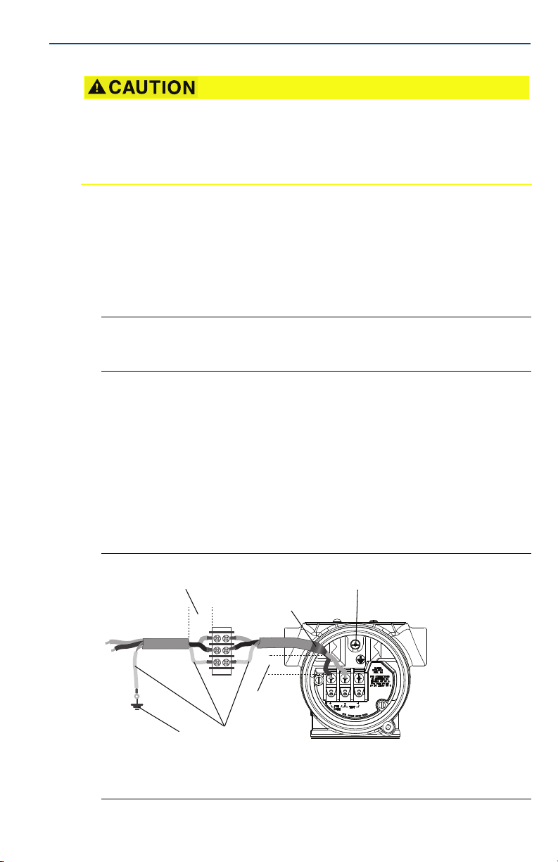
5. Ensure proper grounding. It is important that the instrument cable shield be:
a. Trimmed close and insulated from touching the transmitter housing
b. Connected to the next shield if cable is routed through a junction box
c. Connected to a good earth ground at the power supply end
6. If transient protection is needed, refer to section “Grounding for transient
terminal block” on page 11 for grounding instructions.
7. Plug and seal unused conduit connections.
8. Replace the housing cover.
January 2017
10
Figure 7. Wiring
A. Minimize distance
B. Trim shield and insulate
C. Protective grounding terminal
D. Insulate shield
E. Connect shield back to the power supply ground
Page 11

January 2017
Grounding for transient terminal block
Ground termination is provided on the outside of the electronics housing and
inside the terminal compartment. These grounds are used when the transient
protection terminal blocks are installed. It is recommended that 18 AWG or
larger wire is used to connect housing ground to earth ground (internal or
external).
If the transmitter is currently not wired for power up and communication, follow
Connect the wiring and power up , step 1 through 8. When the transmitter is
properly wired, refer to Figure 7 for internal and external transient grounding
locations.
2.5 Verify configuration
Verify the configuration using any HART capable configuration tool or LOI option code M4. Configuration instructions for a Field Communicator and LOI
are included in this step. See Rosemount 3051 Reference Manual
configuration instructions using AMS™ Device Manager.
Verifying configuration with a Field Communicator
A Rosemount 3051 DD must be installed on the Field Communicator to verify
configuration. Fast Key sequences for the latest DD are shown in Table 3 on
page 11. For Fast Key sequences using legacy DD's, contact your local Emerson
Process Management representative.
Quick Start Guide
for
Note
Emerson recommends installing the latest DD to access the complete functionality. Visit
Emerson.com/Field-Communicator for information on updating the DD Library.
1. Verify device configuration using the fast key sequences in Table 3.
a. A check () indicates the basic configuration parameters. At minimum,
these parameters should be verified as part of configuration and startup.
Table 3. Device Revision 9 and 10 (HART 7), DD Revision 1 Fast Key Sequence
Function
Alarm and Saturation Levels 2, 2, 2, 5, 7 2, 2, 2, 5, 7
Damping 2, 2, 1, 1, 5 2, 2, 1, 1, 5
Range Values 2, 2, 2 2, 2, 2
Tag 2, 2, 7, 1, 1 2, 2, 7, 1, 1
Transfer Function 2, 2, 1, 1, 6 2, 2, 1, 1, 6
Units 2, 2, 1, 1, 4 2, 2, 1, 1, 4
Burst Mode 2, 2, 5, 3 2, 2, 5, 3
Custom Display Configuration 2, 2, 4 2, 2, 4
Date 2, 2, 7, 1, 4 2, 2, 7, 1, 3
Fast Key se quen ce
HART 7 HART 5
11
Page 12

Quick Start Guide
B
A
Table 3. Device Revision 9 and 10 (HART 7), DD Revision 1 Fast Key Sequence
January 2017
Function
Descriptor 2, 2, 7, 1, 5 2, 2, 7, 1, 4
Digital to Analog Trim (4–20 mA Output) 3, 4, 2 3, 4, 2
Disable Configuration Buttons 2, 2, 6, 3 2, 2, 6, 3
Rerange with Keypad 2, 2, 2, 1 2, 2, 2, 1
Loop Test 3, 5, 1 3, 5, 1
Lower Sensor Trim 3, 4, 1, 2 3, 4, 1, 2
Message 2, 2, 7, 1, 6 2, 2, 7, 1, 5
Scaled D/A Trim (4–20 mA Output) 3, 4, 2 3, 4, 2
Sensor Temperature/Trend (3051S) 3, 3, 3 3, 3, 3
Upper Sensor Trim 3, 4, 1, 1 3, 4, 1, 1
Digital Zero Trim 3, 4, 1, 3 3, 4, 1, 3
Password 2, 2, 6, 5 2, 2, 6, 4
Scaled Variable 3, 2, 2 3, 2, 2
HART Revisio n 5 to HART Revision 7 switch 2, 2, 5, 2, 3 2, 2, 5, 2, 3
(1)
Long Tag
Find Device
Simulate Digital Signal
1. Only available in HART Revision 7 mode.
(1)
(1)
Fast Key sequence
HART 7 HART 5
2, 2, 7, 1, 2 N/A
3, 4, 5 N/A
3, 4, 5 N/A
Verifying configuration with LOI
The optional LOI can be used for commissioning the device. The LOI is a
two-button design with internal and external buttons. The internal buttons are
located on the display of the transmitter, while the external buttons are located
underneath the top metal tag. To activate the LOI, push any button. LOI button
functionality is shown on the bottom corners of the display. See Table 4 and
Figure 9 for button operation and menu information.
Figure 8. Internal and External LOI Buttons
A. Internal buttons
B. External buttons
12
Page 13

January 2017
Note
See Figure 10 on page 15 to confirm external button functionality.
Table 4. LOI Button Operation
Figure 9. LOI Menu
Quick Start Guide
Button
Left No SCROLL
Right Yes ENTER
Assign PV
HART Revision
Switch HART revision mode
If the HART configuration tool is not capable of communicating with HART
Revision 7, the Rosemount 3051 will load a generic menu with limited
capability. The following procedures will switch the HART revision mode from
the generic menu:
1. Manual Setup > Device Information > Identification > Message
a. To change to HART Revision 5, Enter: HART5 in the Message field.
b. To change to HART Revision 7, Enter: HART7 in the Message field.
Note
See Table 3 on page 11 to change HART Revision when the correct device driver
is loaded.
13
Page 14

Quick Start Guide
2.6 Trim the transmitter
Devices are calibrated by the factory. Once installed, it is recommended to
perform a zero trim on gage and differential pressure transmitters to eliminate
error due to mounting position or static pressure effects. A zero trim can be
performed using either a Field Communicator or configuration buttons.
For instructions using AMS Device Manager, see the Rosemount 3051 HART
Revision 5 and 7 Reference Manual
Note
When performing a zero trim, ensure that the equalization valve is open and all wet legs
are filled to the correct level.
It is not recommended to zero an absolute transmitter, Rosemount 3051CA or 3051TA models.
1. Choose your trim procedure.
a. Analog zero trim – Sets the analog output to 4 mA.
Also referred to as a “rerange,” it sets the lower range value (LRV) equal
to the measured pressure.
The display and digital HART output remains unchanged.
b. Digital zero trim – Recalibrates the sensor zero.
The LRV is unaffected. The pressure value will be zero (on display and
HART output). 4 mA point may not be at zero.
This requires that the factory calibrated zero pressure is within a range
of 3% of the URL [0 + 3% ⫻ URL].
January 2017
.
14
Example
URV = 250 inH2O
Applied Zero Pressure = + 0.03 ⫻ 250 inH2O = + 7.5 inH2O (compared to
factory settings) values outside this range will be rejected by the transmitter.
Trimming with a Field Communicator
1. Connect the Field Communicator, see “Connect the wiring and power up” on
page 9 for instructions.
2. Follow the HART menu to perform the desired zero trim.
Table 5. Zero Trim Fast Keys
Analog zero (set 4 mA) Digital zero
Fast Key Se quenc e 3, 4, 2 3, 4, 1, 3
Trimming with configuration buttons
A zero trim is to be performed using one of the three possible sets of external
configuration buttons located under the top tag.
To access the configuration buttons, loosen the screw and slide the tag on the
top of the transmitter. Confirm the functionality using Figure 10.
Page 15

January 2017
A
BC
D
Figure 10. External Configuration Buttons
Quick Start Guide
A. LOI
B. Analog zero and span
C. Digital zero
D. Configuration buttons
Use the following procedures to perform a zero trim:
Perform trim with LOI (option M4)
1. Set the transmitter pressure.
2. See Figure 9 on page 13 for the operating menu.
a. Perform an analog zero trim by selecting Rerange.
b. Perform a digital zero trim by selecting Zero Trim.
Perform trim with analog zero and span (option D4)
1. Set the transmitter pressure.
2. Press and hold the Zero button for two seconds to perform an analog zero
trim.
Perform trim with digital zero (option DZ)
1. Set the transmitter pressure.
2. Press and hold the Zero button for two seconds to perform a digital zero
trim.
3.0 Safety instrumented systems installation
For safety certified installations, refer to Rosemount 3051 HART Revision 5 and 7
Reference Manual for installation procedure and system requirements.
15
Page 16

Quick Start Guide
4.0 Product certifications
Rev 1.6
4.1 European Directive Information
A copy of the EU Declaration of Conformity can be found at the end of the Quick
Start Guide. The most recent revision of the EU Declaration of Conformity can
be found at Emerson.com/Rosemount
4.2 Ordinary Location Certification
As standard, the transmitter has been examined and tested to determine that
the design meets the basic electrical, mechanical, and fire protection
requirements by a nationally recognized test laboratory (NRTL) as accredited by
the Federal Occupational Safety and Health Administration (OSHA).
North America
E5 USA Explosionproof (XP) and Dust-Ignitionproof (DIP)
Certificate: 0T2H0.AE
Standards: FM Class 3600 – 2011, FM Class 3615 – 2006, FM Class 3810 – 2005,
Markings: XP CL I, DIV 1, GP B, C, D; DIP CL II, DIV 1, GP E, F, G; CL III;
I5 USA Intrinsic Safety (IS) and Nonincendive (NI)
Certificate: FM16US0120X
Standards: FM Class 3600 – 2011, FM Class 3610 – 2010, FM Class 3611 – 2004,
Markings: IS CL I, DIV 1, GP A, B, C, D; CL II, DIV 1, GP E, F, G; Class III; DIV 1 when
Special Conditions for Safe Use (X):
1. The Rosemount 3051 Transmitter housing contains aluminum and is considered a
potential risk of ignition by impact or friction. Care must be taken into account during
installation and use to prevent impact and friction.
2. The Rosemount 3051 Transmitter with the transient terminal block (option code T1)
will not pass the 500 Vrms dielectric strength test and this must be taken into account
during installation.
IE USA FISCO
Certificate: FM16US0120X
Standards: FM Class 3600 – 2011, FM Class 3610 – 2010, FM Class 3611 – 2004,
Markings: IS CL I, DIV 1, GP A, B, C, D when connected per Rosemount drawing
Special Conditions for Safe Use (X):
1. The Rosemount 3051 Transmitter housing contains aluminum and is considered a
potential risk of ignition by impact or friction. Care must be taken into account during
installation and use to prevent impact and friction.
ANSI/NEMA 250 – 2003
T5(–50 °C ≤ T
FM Class 3810 – 2005, ANSI/NEMA 250 - 2008
connected per Rosemount drawing 03031-1019; NI CL 1, DIV 2, GP A, B,
C, D; T4(–50 °C ≤ T
T4(–50 °C ≤ T
FM Class 3810 – 2005
03031-1019 (–50 °C ≤ T
≤ +85 °C); Factory Sealed; Type 4X
a
≤ +60 °C) [Fieldbus/PROFIBUS®]; Type 4x
a
.
≤ +70 °C) [HART], T5(–50 °C ≤ Ta ≤ +40 °C) [HART];
a
≤ +60 °C); Type 4x
a
January 2017
16
Page 17

January 2017
2. The Rosemount 3051 Transmitter with the transient terminal block (option code T1)
C6 Canada Explosionproof, Dust-Ignitionproof, Intrinsic Safety and Nonincendive
E6 Canada Explosionproof, Dust-Ignitionproof and Division 2
Europe
E8 ATEX Flameproof and Dust
Quick Start Guide
will not pass the 500 Vrms dielectric strength test and this must be taken into account
during installation.
Certificate: 1053834
Standards: ANSI/ISA 12.27.01-2003, CSA Std. C22.2 No. 30-M1986,
CSA Std. C22.2 No.142-M1987, CSA Std. C22.2. No.157-92,
CSA Std. C22.2 No. 213-M1987
Markings: Explosionproof for Class I, Division 1, Groups B, C and D; Suitable for Class
I, Zone 1, Group IIB+H2, T5; Dust-Ignitionproof Class II, Division 1, Groups
E, F, G; Class III Division 1; Intrinsically Safe Class I, Division 1 Groups A, B,
C, D when connected in accordance with Rosemount drawing
03031-1024, Temperature Code T3C; Suitable for Class I, Zone 0; Class I
Division 2 Groups A, B, C and D, T5; Suitable for Class I Zone 2, Group IIC;
Type 4X; Factory Sealed; Single Seal (See drawing 03031-1053)
Certificate: 1053834
Standards: ANSI/ISA 12.27.01-2003, CSA Std. C22.2 No. 30-M1986,
CSA Std. C22.2 No.142-M1987, CSA Std. C22.2 No. 213-M1987
Markings: Explosionproof Class I, Division 1, Groups B, C and D; Suitable for Class I,
Zone 1, Group IIB+H2, T5; Dust-Ignitionproof for Class II and Class III,
Division 1, Groups E, F and G; Class I, Division 2, Groups A, B, C and D;
Suitable for Class I Zone 2, Group IIC; Type 4X; Factory Sealed; Single Seal
(See drawing 03031-1053)
Certificate: KEMA00ATEX2013X; Baseefa11ATEX0275X
Standards: EN60079-0:2012 + A11:2013, EN60079-1:2014, EN60079-26:2015,
EN60079-31:2009
Markings: II
1
/2 G Ex db IIC T6...T4 Ga/Gb, T6(–60 °C ≤ Ta ≤ +70 °C),
T4/T5(–60 °C ≤ T
II 1 D Ex ta IIIC T95 °C T
≤ +80 °C);
a
105 °C Da (–20 °C ≤ Ta ≤ +85 °C)
500
Table 6. Process Temperature
Temperature class Process temperature
T6 –60 to +70 °C
T5 –60 to +80 °C
T5 –60 to +120 °C
Special Conditions for Safe Use (X):
1. This device contains a thin wall diaphragm. Installation, maintenance and use shall
take into account the environmental conditions to which the diaphragm will be
subjected. The manufacturer's instructions for installation and maintenance shall be
followed in detail to assure safety during its expected lifetime.
2. Flameproof joints are not intended for repair.
3. Non-standard paint options may cause risk from electrostatic discharge. Avoid
installations that could cause electrostatic build-up on painted surfaces, and only clean
the painted surfaces with a damp cloth. If paint is ordered through a special option
code, contact the manufacturer for more information.
17
Page 18

Quick Start Guide
4. Some variants of the equipment have reduced markings on the nameplate. Refer to
the Certificate for full equipment marking.
I1 ATE X Int rin sic Safety a nd D ust
Certificate: BAS97ATEX1089X; Baseefa11ATEX0275X
Standards: EN60079-0:2012, EN60079-11:2012, EN60079-31:2009
Markings: HART: II 1 G Ex ia IIC T5/T4 Ga, T5(–60 °C ≤ T
Table 7. Input Parameters
Parameter HART Fieldbus/PROFIBUS
Volt age U
Current I
Power P
Capacitance C
Inductance L
Special Conditions for Safe Use (X):
1. The apparatus is not capable of withstanding the 500 V insulation test required by
clause 6.3.12 of EN60079-11:2012. This must be taken into account when installing
the apparatus.
2. The enclosure may be made of aluminum alloy and given a protective polyurethane
paint finish; however care should be taken to protect it from impact or abrasion if
located in Zone 0.
3. Some variants of the equipment have reduced markings on the nameplate. Refer to
the Certificate for full equipment marking.
IA ATEX FIS CO
Certificate: BAS97ATEX1089X
Standards: EN60079-0:2012, EN60079-11:2009
Markings: II 1 G Ex ia IIC T4 Ga (–60 °C ≤ T
Table 8. Input Parameters
T4(–60 °C ≤ T
≤ +70 °C)
a
Fieldbus/PROFIBUS: II 1 G Ex ia IIC Ga T4(–60 °C ≤ T
DUST: II 1 D Ex ta IIIC T95 °C T
i
i
i
i
i
30 V 30 V
200 mA 300 mA
0.9 W 1.3 W
0.012 μF 0 μF
0 mH 0 mH
500
a
January 2017
≤ +40 °C),
a
≤ +60 °C)
a
105 °C Da (–20 °C ≤ Ta ≤ +85 °C)
≤ +60 °C)
18
Parameter FISCO
Volt age U
i
Current I
i
Power P
i
Capacitance C
Inductance L
i
i
17.5 V
380 mA
5.32 W
<5 nF
<10 μH
Special Conditions for Safe Use (X):
1. The apparatus is not capable of withstanding the 500 V insulation test required by
clause 6.3.12 of EN60079-11:2012. This must be taken into account when installing
the apparatus.
2. The enclosure may be made of aluminum alloy and given a protective polyurethane
paint finish; however care should be taken to protect it from impact or abrasion if
located in Zone 0.
Page 19

January 2017
N1 ATE X Typ e n a nd D ust
Special Conditions for Safe Use (X):
1. This apparatus is not capable of withstanding the 500 V insulation test that is required
2. Some variants of the equipment have reduced markings on the nameplate. Refer to
International
E7 IECEx Flameproof and Dust
Table 9. Process Temperature
Quick Start Guide
Certificate: BAS00ATEX3105X; Baseefa11ATEX0275X
Standards: EN60079-0:2012, EN60079-15:2010, EN60079-31:2009
Markings: II 3 G Ex nA IIC T5 Gc (–40 °C ≤ T
II 1 D Ex ta IIIC T95 °C T
500
≤ +70 °C);
a
105 °C Da (–20 °C ≤ Ta ≤ +85 °C)
by EN60079-15. This must be taken into account when installing the apparatus.
the Certificate for full equipment marking.
Certificate: IECEx KEM 09.0034X; IECEx BAS 10.0034X
Standards: IEC60079-0:2011, IEC60079-1:2014-06, IEC60079-26:2014-10,
IEC60079-31:2008
Markings: Ex db IIC T6...T4 Ga/Gb, T6(–60 °C ≤ T
T4/T5(–60 °C ≤ T
Ex ta IIIC T95 °C T
Temperature class Process temperature
T6
T5
T4
≤ +80 °C);
a
105 °C Da (–20 °C ≤ Ta ≤ +85 °C)
500
–60 to +70 °C
–60 to +80 °C
–60 to +80 °C
≤ +70 °C),
a
Special Conditions for Safe Use (X):
1. This device contains a thin wall diaphragm. Installation, maintenance and use shall
take into account the environmental conditions to which the diaphragm will be
subjected. The manufacturer's instructions for installation and maintenance shall be
followed in detail to assure safety during its expected lifetime.
2. Flameproof joints are not intended for repair.
3. Non-standard paint options may cause risk from electrostatic discharge. Avoid
installations that could cause electrostatic build-up on painted surfaces, and only clean
the painted surfaces with a damp cloth. If paint is ordered through a special option
code, contact the manufacturer for more information.
4. Some variants of the equipment have reduced markings on the nameplate. Refer to
the Certificate for full equipment marking.
I7 IECEx Intrinsic Safety
Certificate: IECEx BAS 09.0076X
Standards: IEC60079-0:2011, IEC60079-11:2011
Markings: HART: Ex ia IIC T5/T4 Ga, T5(–60 °C ≤ T
Fieldbus/PROFIBUS: Ex ia IIC T4(–60 °C ≤ T
≤ +40 °C), T4(–60 °C ≤ Ta ≤ +70 °C)
a
≤ +60 °C)
a
19
Page 20

Quick Start Guide
Table 10. Input Parameters
Parameter HART Fieldbus/PROFIBUS
Volt age U
Current I
Power P
Capacitance C
Inductance L
Special Conditions for Safe Use (X):
1. If the apparatus is fitted with optional 90 V transient suppressor, it is not capable of
withstanding the 500 V insulation test required by IEC60079-11. This must be taken
into account when installing the apparatus.
2. The enclosure may be made of aluminum alloy and given a protective polyurethane
paint finish; however, care should be taken to protect it from impact or abrasion if
located in Zone 0.
IECEx Mining (Special A0259)
Certificate: IECEx TSA 14.0001X
Standards: IEC60079-0:2011, IEC60079-11:2011
Markings: Ex ia I Ma (–60 °C ≤ T
Table 11. Input Parameters
Parameter HART Fieldbus/PROFIBUS FISCO
Volt age U
Current I
Power P
Capacitance C
Inductance L
Special Conditions for Safe Use (X):
1. If the apparatus is fitted with optional 90 V transient suppressor, it is not capable of
withstanding the 500 V insulation test required by IEC60079-11. This must be taken
into account when installing the apparatus.
2. It is a condition of safe use that the above input parameters shall be taken into account
during installation.
3. It is a condition of manufacture that only the apparatus fitted with housing, covers and
sensor module housing made out of stainless steel are used in Group I applications.
N7 IECEx Type n
Certificate: IECEx BAS 09.0077X
Standards: IEC60079-0:2011, IEC60079-15:2010
Markings: Ex nA IIC T5 Gc (–40 °C ≤ T
Special Condition for Safe Use (X):
1. The apparatus is not capable of withstanding the 500 V insulation test required by
IEC60079-15. This must be taken into account when installing the apparatus.
January 2017
i
i
i
i
i
i
i
i
i
i
30 V 30 V
200 mA 300 mA
0.9 W 1.3 W
0.012 μF 0 μF
0 mH 0 mH
≤ +70 °C)
a
30 V 30 V 17.5 V
200 mA 300 mA 380 mA
0.9 W 1.3 W 5.32 W
0.012 μF 0 μF <5 nF
0 mH 0 mH <10 μH
≤ +70 °C)
a
20
Page 21

January 2017
Brazil
E2 INMETRO Flameproof
Special Conditions for Safe Use (X):
1. This device contains a thin wall diaphragm. Installation, maintenance and use shall
2. In case of repair, contact the manufacturer for information on the dimensions of the
3. The capacitance of the wrap around label, being 1.6 nF, exceeds the limit in Table 9 of
I2 INMETRO Intrinsic Safety
Table 12. Input Parameters
Quick Start Guide
Certificate: UL-BR 13.0643X
Standards: ABNT NBR IEC60079-0:2008 + Errata 1:2011,
ABNT NBR IEC60079-1:2009 + Errata 1:2011,
ABNT NBR IEC60079-26:2008 + Errata 1:2008
Markings: Ex d IIC T6/T5 Ga/Gb, T6(–50 °C ≤ T
≤ +65 °C), T5(–50 °C ≤ Ta ≤ +80 °C)
a
take into account the environmental conditions to which the diaphragm will be
subjected. The manufacturer's instructions for installation and maintenance shall be
followed in detail to assure safety during its expected lifetime.
flameproof joints.
ABNT NBR IEC 60079-0. The user shall determine suitability for the specific
application.
Certificate: UL-BR 13.0584X
Standards: ABNT NBR IEC60079-0:2008 + Errata 1:2011, ABNT NBR
IEC60079-11:2009
Markings: HART: Ex ia IIC T5/T4 Ga, T5(–60 °C ≤ T
Fieldbus/PROFIBUS: Ex ia IIC T4 Ga (–60 °C ≤ T
≤ +40 °C), T4(–60 °C ≤ Ta ≤ +70 °C)
a
≤ +60 °C)
a
Parameter HART Fieldbus/PROFIBUS
Voltag e U
i
Current I
i
Power P
i
Capacitance C
Inductance L
i
i
30 V 30 V
200 mA 300 mA
0.9 W 1.3 W
0.012 μF 0 μF
0 mH 0 mH
Special Conditions for Safe Use (X):
1. If the equipment is fitted with an optional 90 V transient suppressor, it is not capable of
withstanding the 500 V insulation test required by ABNT NBR IRC 60079-11. This must
be taken into account when installing the equipment.
2. The enclosure may be made of aluminum alloy and given a protective polyurethane
paint finish; however, care should be taken to protect it from impact or abrasion if
located in Zone 0.
IB INMETRO FISCO
Certificate: UL-BR 13.0584X
Standards: ABNT NBR IEC60079-0:2008 + Errata 1:2011,
ABNT NBR IEC60079-11:2009
Markings: Ex ia IIC T4 Ga (–60 °C ≤ T
≤ +60 °C)
a
21
Page 22

Quick Start Guide
Table 13. Input Parameters
Parameter FISCO
Volt age U
Current I
Power P
Capacitance C
Inductance L
Special Conditions for Safe Use (X):
1. If the equipment is fitted with an optional 90 V transient suppressor, it is not capable of
withstanding the 500 V insulation test required by ABNT NBR IEC 60079-11. This must
be taken into account when installing the equipment.
2. The enclosure may be made of aluminum alloy and given a protective polyurethane
paint finish; however, care should be taken to protect it from impact or abrasion if
located in Zone 0.
China
E3 China Flameproof
Certificate: GYJ14.1041X; GYJ15.1368X [Flowmeters]
Standards: GB12476-2000; GB3836.1-2010, GB3836.2-2010, GB3836.20-2010
Markings: Ex d IIC T6/T5 Ga/Gb, T6(–50 °C ≤ T
Special Conditions for Safe Use (X):
1. The relation between ambient temperature arrange and temperature class is as
follow s:
January 2017
i
i
i
i
i
17.5 V
380 mA
5.32 W
<5 nF
<10 μH
≤ +65 °C), T5(–50 °C ≤ Ta ≤ +80 °C)
a
22
T
a
–50 °C~+80 °C T5
–50 °C~+65 °C T6
Tem per atu re c las s
When used in a combustible d ust environment, t he maximum ambient temperature is
80 °C.
2. The earth connection facility in the enclosure should be connected reliably.
3. Cable entry certified by notified body with type of protection Ex d IIC in accordance
with GB3836.1-2000 and GB3836.2-2000, should be applied when installed in a
hazardous location. When used in combustible dust environment, cable entry in
accordance with IP66 or higher level should be applied.
4. Obey the warning “Keep tight when the circuit is alive.”
5. End users are not permitted to change any internal components.
6. During installation, use and maintenance of this product, observe the following
standards: GB3836.13-1997, GB3836.15-2000, GB3836.16-2006, GB50257-1996,
GB12476.2-2006, GB15577-2007.
I3 China Intrinsic Safety
Certificate: GYJ13.1362X; GYJ15.1367X [Flowmeters]
Standards: GB3836.1-2010, GB3836.4-2010, GB3836.20-2010, GB12476.1-2000
Markings: Ex ia IIC Ga T4/T5
Page 23

January 2017
Special Conditions for Safe Use (X):
1. Symbol “X” is used to denote specific conditions of use:
2. The relation between T code and ambient temperature range is:
3. Intrinsically Safe parameters:
Quick Start Guide
a. If the apparatus is fitted with an optional 90 V transient suppressor, it is not
capable of withstanding the 500 V insulation test for 1 minute. This must be
taken into account when installing the apparatus.
b. The enclosure may be made of aluminum alloy and given a protective
polyurethane paint finish; however, care should be taken to protect it from
impact or abrasion if located in Zone 0.
Model T code Temperature range
HART T5 –60 °C ≤ Ta ≤ +40 °C
HART T4 –60 °C ≤ Ta ≤ +70 °C
Fieldbus/PROFIBUS/FISCO T4 –60 °C ≤ Ta ≤ +60 °C
Parameter HART Fieldbus/PROFIBUS FISCO
Volt age U
i
Current I
i
Power P
i
Capacitance C
Inductance L
i
i
30 V 30V 17.5 V
200 mA 300 mA 380 mA
0.9 W 1.3 W 5.32 W
0.012 μF 0 μF <5 nF
0 mH 0mH <10 μH
Note
FISCO parameters apply to both Group IIC and IIB.
[For Flowmeters] When Rosemount 644 Temperature Transmitter is used, the
transmitter should be used with Ex-certified associated apparatus to establish explosion
protection system that can be used in explosive gas atmospheres. Wiring and terminals
should comply with the instruction manual of both Rosemount 644 and associated
apparatus. The cables between Rosemount 644 and associated apparatus should be
shielded cables (the cables must have insulated shield). The shielded cable has to be
grounded reliably in a non-hazardous area.
4. Transmitters comply with the requirements for FISCO field devices specified in
IEC60079-27:2008. For the connection of an intrinsically safe circuit in accordance
with FISCO Model, FISCO parameters are listed in the table above.
5. The product should be used with Ex-certified associated apparatus to establish
explosion protection system that can be used in explosive gas atmospheres. Wiring
and terminals should comply with the instruction manual of the product and
associated apparatus.
6. The cables between this product and associated apparatus should be shielded
cables (the cables must have insulated shield). The shielded cable has to be
grounded reliably in a non-hazardous area.
23
Page 24

Quick Start Guide
7. End users are not permitted to change any intern components but to settle the
problem in conjunction with the manufacturer to avoid damage to the product.
8. During installation, use and maintenance of this product, observe the following
standards: GB3836.13-1997, GB3836.15-2000, GB3836.16-2006, GB50257-1996,
GB12476.2-2006, GB15577-2007.
N3 China Type n
Certificate: GYJ15.1105X
Standards: GB3836.1-2010, GB3836.8-2003
Markings: Ex nA nL IIC T5 Gc (–40 °C ≤ T
Special Condition for Safe Use (X):
1. Symbol “X” is used to denote specific conditions of use: The apparatus is not capable of
withstanding the 500 V test to earth for one minute. The must be taken into
consideration during installation.
Japan
E4 Japan Flameproof
Certificate: TC20577, TC20578, TC20583, TC20584 [HART]; TC20579, TC20580,
Markings: Ex d IIC T5
Technical Regulations Customs Union (EAC)
EM EAC Flameproof
Certificate: RU C-US.GB05.B.01197
Markings: Ga/Gb Ex d IIC T5/T6 X, T5(–60 °C ≤ T
Special Condition for Safe Use (X):
1. See certificate for special conditions.
IM EAC Intrinsically Safe
Certificate: RU C-US.GB05.B.01197
Markings: HART: 0Ex ia IIC T4/T5 Ga X, T4(–60 °C ≤ T
Special Condition for Safe Use (X):
1. See certificate for special conditions.
≤ +70 °C)
a
TC20581, TC20582 [Fieldbus]
≤ +80 °C), T6(–60 °C ≤ Ta ≤ +65 °C)
a
≤ +70 °C),
T5(–60 °C ≤ T
≤ +40 °C)
a
a
Fieldbus/PROFIBUS: 0Ex ia IIC T4 Ga X (–60 °C ≤ T
≤ +60 °C)
a
January 2017
24
Combinations
K2 Combination of E2 and I2
K5 Combination of E5 and I5
K6 Combination of C6, E8, and I1
K7 Combination of E7, I7, and N7
K8 Combination of E8, I1, and N1
KB Combination of E5, I5, and C6
KD Combination of E8, I1, E5, I5, and C6
KM Combination of EM and IM
Conduit plugs and adapters
IECEx Flameproof and Increased Safety
Certificate: IECEx FMG 13.0032X
Standards: IEC60079-0:2011, IEC60079-1:2007, IEC60079-7:2006-2007
Markings: Ex de IIC Gb
Page 25

January 2017
ATEX Flameproof and Increased Safety
Certificate: FM13ATEX0076X
Standards: EN60079-0:2012, EN60079-1:2007, IEC60079-7:2007
Markings: II 2 G Ex de IIC Gb
Table 14. Conduit Plug Thread Sizes
Table 15. Thread Adapter Thread Sizes
Special Conditions for Safe Use (X):
1. When the thread adapter is used with an enclosure in type of protection increased
2. The blanking plug shall not be used with an adapter.
3. Blanking Plug and Threaded Adapter shall be either NPT or Metric thread forms. G
Quick Start Guide
Thread Identification mark
M20 ⫻ 1.5 M20
1
/2–14 NPT
Male thread Identification mark
M20 ⫻ 1.5–6H M20
1
/2–14 NPT
3
/4–14 NPT
Female t hread Identification mark
M20 ⫻ 1.5–6H M20
1
/2–14 NPT
G1/2 G1/2
1
/2 NPT
1
/2–14 NPT
3
/4–14 NPT
1
/2–14 NPT
safety “e” the entry thread shall be suitably sealed in order to maintain the ingress
protection rating (IP) of the enclosure.
thread forms are only acceptable for existing (legacy) equipment installations.
1
/2
Additional Certifications
SBS American Bureau of Shipping (ABS) Type Approval
Certificate: 09-HS446883A-5-PDA
Intended Use: Marine and Offshore Applications — Measurement of either gauge
or absolute pressure for liquid, gas, and vapor.
SBV Bureau Veritas (BV) Type Approval
Certificate: 23155
Requirements: Bureau Veritas Rules for the Classification of Steel Ships
Application: Class notations: AUT-UMS, AUT-CCS, AUT-PORT and AUT-IMS;
Pressure transmitter type 3051 cannot be installed on diesel
engines
SDN Det Norske Veritas (DNV) Type Approval
Certificate: TAA000004F
Intended Use: DNV GL Rules for Classification — Ships and offshore units
25
Page 26

Quick Start Guide
SLL Lloyds Register (LR) Type Approval
C5 Custody Transfer - Measurement Canada Accuracy Approval
January 2017
Application:
Location classes
Tem pe ra tu r e D
Humidity B
Vibration A
EMC B
Enclosure D
Certificate: 11/60002
Application: Environmental categories ENV1, ENV2, ENV3, and ENV5
Certificate: AG-0226; AG-0454; AG-0477
26
Page 27

January 2017
Figure 11. Rosemount 3051 Declaration of Conformity
Quick Start Guide
27
Page 28

Quick Start Guide
January 2017
28
Page 29

January 2017
Quick Start Guide
29
Page 30

Quick Start Guide
January 2017
30
Page 31

January 2017
ᴹ
China RoHS
㇑᧗⢙䍘䎵䗷ᴰབྷ⎃ᓖ䲀٬Ⲵ䜘Ԧරࡇ㺘
Rosemount 3051
List of Rosemount 3051 Parts with China RoHS Concentration above MCVs
䜘Ԧ〠
Part Name
ᴹᇣ⢙䍘䍘
/ Hazardous Substances
䫵
Lead
(Pb)
⊎
Mercury
(Hg)
䭹
Cadmium
(Cd)
ޝԧ䬜䬜
Hexavalent
Chromium
(Cr +6)
ཊⓤ㚄㚄㤟
Polybrominated
biphenyls
(PBB)
ཊⓤ㚄㚄㤟䟊
Polybrominated
diphenyl ethers
(PBDE)
⭥ᆀ㓴Ԧ
Electronics
Assembly
XO O O O O
༣փ㓴Ԧ
Housing
Assembly
XO O X O O
Րᝏಘ㓴Ԧ
Sensor
Assembly
XO O X O O
ᵜ㺘Ṭ㌫ᦞ
SJ/T11364
Ⲵ㿴ᇊ㘼ࡦ
This table is proposed in accordance with the provision of SJ/T11364.
O:
Ѫ䈕䜘ԦⲴᡰᴹ൷䍘ᶀᯉѝ䈕ᴹᇣ⢙䍘Ⲵ䟿൷վҾ
GB/T 26572
ᡰ㿴ᇊⲴ䲀䟿㾱≲
O: Indicate that said hazardous substance in all of the homogeneous materials for this part is below the limit requirement of
GB/T 26572.
X:
Ѫ൘䈕䜘Ԧᡰ֯⭘Ⲵᡰᴹ൷䍘ᶀᯉ䟼ˈ㠣ቁᴹа㊫൷䍘ᶀᯉѝ䈕ᴹᇣ⢙䍘Ⲵ䟿儈Ҿ
GB/T 26572
ᡰ㿴ᇊⲴ䲀䟿㾱≲
X: Indicate that said hazardous substance contained in at least one of the homogeneous materials used for this part is above
the limit requirement of GB/T 26572.
Quick Start Guide
31
Page 32

Global Headquarters
Emerson Automation Solutions
6021 Innovation Blvd.
Shakopee, MN 55379, USA
+1 800 999 9307 or +1 952 906 8888
+1 952 949 7001
RFQ.RMD-RCC@Emerson.com
North America Regional Office
Emerson Automation Solutions
8200 Market Blvd.
Chanhassen, MN 55317, USA
+1 800 999 9307 or +1 952 906 8888
+1 952 949 7001
RMT-NA.RCCRFQ@Emerson.com
Latin America Regional Office
Emerson Automation Solutions
1300 Concord Terrace, Suite 400
Sunrise, FL 33323, USA
+1 954 846 5030
+1 954 846 5121
RFQ.RMD-RCC@Emerson.com
Europe Regional Office
Emerson Automation Solutions
Neuhofstrasse 19a P.O. Box 1046
CH 6340 Baar
Switzerland
+41 (0) 41 768 6111
+41 (0) 41 768 6300
RFQ.RMD-RCC@Emerson.com
Asia Pacific Regional Office
Emerson Automation Solutions
1 Pandan Crescent
Singapore 128461
+65 6777 8211
+65 6777 0947
Enquiries@AP.Emerson.com
Middle East and Africa Regional Office
Emerson Automation Solutions
Emerson FZE P.O. Box 17033
Jebel Ali Free Zone - South 2
Dubai, United Arab Emi rates
+971 4 8118100
+971 4 8865465
RFQ.RMTMEA@Emerson.com
*00825-0100-4007*
Quick Start Guide
00825-0100-4007, Rev DD
Linkedin.com/company/Emerson-Automation-Solutions
Twitter.com/Rosemount_News
Facebook.com/Rosemount
Youtube.com/us er/RosemountMeasur ement
Google.com/+RosemountMeasurement
Standard Terms and Conditions of Sale can be found on the Te rm s
and Conditions of Sale page.
The Emerson logo is a trademark and service mark of Emerson
Electric Co.
AMS, Rosemount, and Rosemount logotype are trademarks of
Emerson.
DTM is a trademark of the FDT Group.
HART is a registered trademark of the FieldComm Group.
NEMA is a registered trademark and service mark of the National
Electrical Manufacturers Association.
PROFIBUS is a registered trademark of PROFINET International (PI).
All other marks are the property of their respective owners.
© 2017 Emerson. All rights reserved.
January 2017
 Loading...