

3051HT Hygienic Pressure Transmitter with 4-20 mA HART Revision 5 and 7 Protocol
Table of contents
 Loading...
Rosemount 3051HT Hygienic Pressure Transmitter with 4-20 mA HART Revision 5 and 7 Protocol Quick Start Guide

Quick Start Guide
00825-0100-4091, Rev DA
June 2020
Rosemount™ 3051HT Hygienic Pressure
Transmitter
with 4–20 mA HART® Revision 5 and 7
Protocol

Quick Start Guide June 2020
NOTICE
This guide provides basic guidelines for the Rosemount 3051HT Transmitter. It does not provide
instructions for configuration, diagnostics, maintenance, service, troubleshooting, Explosion-proof,
Flameproof, or intrinsically safe (I.S.) installations.
WARNING
Explosions could result in death or serious injury.
Installation of device in an explosive environment must be in accordance with appropriate local,
national, and international standards, codes, and practices.
In an explosion-proof/flameproof installation, do not remove the transmitter covers when power is
applied to the unit.
Ensure device is installed in accordance with intrinsically safe or non-incendive field practices.
Before connecting a handheld communicator in an explosive atmosphere, ensure the instruments are
installed in accordance with intrinsically safe or non-incendive field wiring practices.
Verify that the operating environment of the gauge is consistent with the appropriate hazardous
locations certifications.
Electrical shock can result in death or serious injury.
Care must be taken during transportation of power module to prevent electrostatic charge build-up.
Device must be installed to ensure a minimum antenna separation distance of 8 in. (20 cm) from all
persons.
Physical access
Unauthorized personnel may potentially cause significant damage to and/or misconfiguration of end
users’ equipment. This could be intentional or unintentional and needs to be protected against.
Physical security is an important part of any security program and fundamental to protecting your
system. Restrict physical access by unauthorized personnel to protect end users’ assets. This is true for
all systems used within the facility.
Process leaks may cause harm or result in death.
Handle the device carefully.
Failure to follow safe installation guidelines could result in death or serious injury.
Ensure only qualified personnel perform the installation.
Apply wrench only to the flats, not on housing.
The battery is not replaceable in a hazardous location.
Contents
System readiness......................................................................................................................... 3
Transmitter installation................................................................................................................ 4
Product certifications................................................................................................................. 18
2 Emerson.com/Rosemount

June 2020 Quick Start Guide
1 System readiness
1.1 Confirm HART® Revision capability
• If using HART based control or asset management systems, confirm the
HART capability of those systems prior to transmitter installation. Not all
systems are capable of communicating with HART Revision 7 protocol.
This transmitter can be configured for either HART Revision 5 or 7
protocol.
• For instructions on how to change the HART Revision of your transmitter,
see Switch HART Revision mode.
1.2 Confirm correct device driver
• Verify the latest device driver (DD/DTM™) is loaded on your systems to
ensure proper communications.
• Download the latest device driver at Emerson.com or
FieldCommGroup.org.
Rosemount 3051 device revisions and drivers
Table 1-1 provides the information necessary to ensure you have the correct
device driver and documentation for your device.
Table 1-1: Rosemount 3051 Device Revisions and Files
Identify
Software
release date
Dec-11 01 7 10 See
(1) Device driver file names use device and DD revision, e.g. 10_01. HART Protocol is
designed to enable legacy device driver revisions to continue to communicate
with new HART devices. To access new functionality, the new device driver must
be downloaded. It is recommended to download new device driver files to
ensure full functionality.
(2) HART Revision 5 and 7 Selectable, Power Diagnostics, Safety Certified, Local
Operator Interface, Process Alerts, Scaled Variable, Configurable Alarms,
Expanded Engineering Units.
Quick Start Guide 3
device
HART
software
revision
Find device driver Review
HART
universal
revision
5 9
Device
revision
(1)
functionality
Changes to
software
(2)
of changes.
(2)
for list

Quick Start Guide June 2020
2 Transmitter installation
2.1 Mount the transmitter
Place the transmitter to the desired orientation before mounting.
Transmitter must not be securely mounted or clamped in place when
changing transmitter orientation.
Conduit entry orientation
When installing a Rosemount 3051HT, it is recommended installing so a
conduit entry faces downward or parallel to the ground to maximize
drainability when cleaning.
Environmental seal for housing
Thread sealing (PTFE) tape or paste on male threads of conduit is required to
provide a watertight/dustproof conduit seal and meets requirements of
NEMA® Type 4X, IP66, IP68, and IP69K. Consult factory if other Ingress
Protection ratings are required.
Note
IP69K rating only available on units with a SST housing and option code V9 in
the model string.
For M20 threads, install conduit plugs to full thread engagement or until
mechanical resistance is met.
In-line gauge transmitter orientation
The low side pressure port (atmospheric reference) on the in-line gage
transmitter is located on the neck of the transmitter via a protected gage
vent (See Figure 2-1).
Keep the vent path free from obstructions including but not limited to paint,
dust, and viscous fluids by mounting the transmitter so the process can drain
away.
4 Emerson.com/Rosemount
June 2020 Quick Start Guide
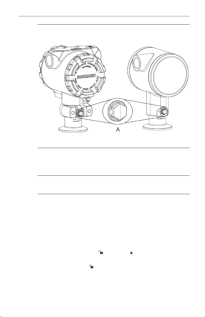
Figure 2-1: In-line Protected Gage Vent Low Side Pressure Port
Aluminum Polished 316 SST
A. Low side pressure port (atmospheric reference)
Clamping
When installing clamp, follow recommended torque values provided by
gasket manufacturer.
Note
To maintain performance, torquing a 1.5-in. Tri Clamp beyond 50 in-lb. is
not recommended on pressure ranges below 20 psi.
2.2
Quick Start Guide 5
Set the switches
Prerequisites
Set alarm and security switch configuration before installation as shown in
Figure 2-2 and Figure 2-3.
• The alarm switch sets the analog output alarm to high or low.
• Default alarm is high.
• The security switch allows ( ) or prevents ( ) any configuration of the
transmitter.
• Default security is off (
Use the following procedure to change the switch configuration:
).
Quick Start Guide June 2020
Procedure
1. If the transmitter is installed, secure the loop, and remove power.
2. Remove the housing cover opposite the field terminal side. Do not
remove the instrument cover in explosive atmospheres when the
circuit is live.
3. Slide the security and alarm switches into the preferred position
using a small screwdriver.
4. Reattach the transmitter cover.
• The covers must only be capable of being released or removed
with the aid of a tool to comply with applicable ordinary locations
requirements.
• The cover must be fully engaged to comply with explosion-proof
requirements.
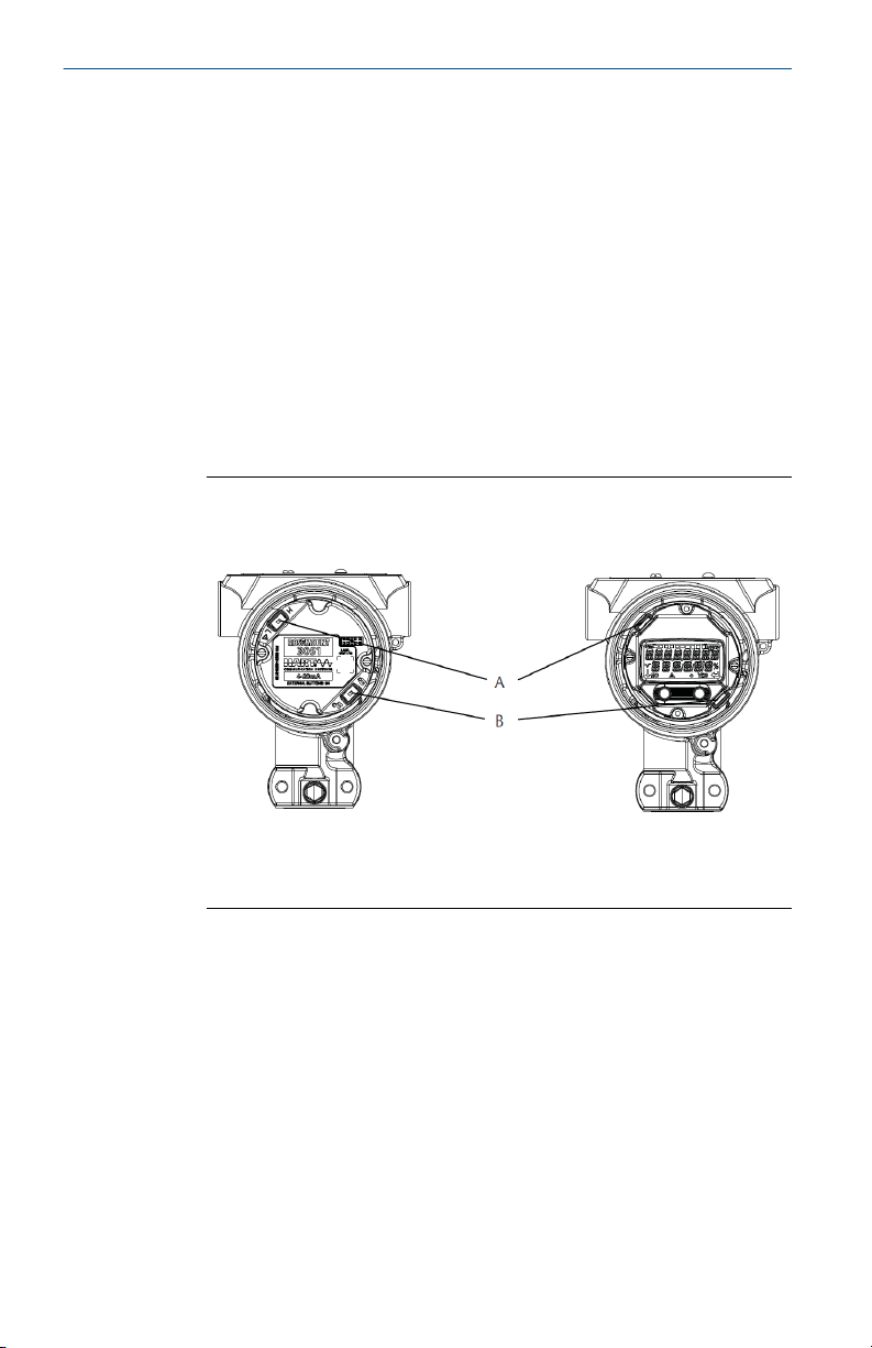
Figure 2-2: Transmitter Electronics Board - Aluminum
Without LCD display With LOI or LCD display
A. Alarm
B. Security
6 Emerson.com/Rosemount
DP
A
B
D
E
C
June 2020 Quick Start Guide
Figure 2-3: Transmitter Electronics Board - Polished 316 SST
Without LCD display With LOI or LCD display
A. Alarm
B. Security
2.3 Connect the wiring and power up
Figure 2-4: Transmitter Wiring Diagrams (4–20 mA) - Aluminum
A. Minimize distance
B. Trim shield and insulate
C. Protective grounding terminal
D. Insulate shield
E. Connect shield back to the power supply ground
Quick Start Guide 7
DP
A
B
D
E
C
Quick Start Guide June 2020
Figure 2-5: Transmitter Wiring Diagrams (4–20 mA) - Polished 316 SST
A. Minimize distance
B. Trim shield and insulate
C. Protective grounding terminal
D. Insulate shield
E. Connect shield back to the power supply ground
Shielded twisted pair cable should be used for best results. Use 24 AWG or
larger wire that does not exceed 5,000 ft. (1,500 m) in length. If applicable,
install wiring with a drip loop. Arrange the drip loop so the bottom is lower
than the conduit connections and the transmitter housing.
CAUTION
• Installation of the transient protection terminal block does not provide
transient protection unless the Rosemount 3051HT case is properly
grounded.
• Do not run signal wiring in conduit or open trays with power wiring, or
near heavy electrical equipment.
• Do not connect the powered signal wiring to the test terminals. Power
could damage the test diode in the terminal block.
Procedure
1. Remove the housing cover on the FIELD TERMINALS side.
2. Connect the positive lead to the “+” terminal (PWR/COMM) and the
negative lead to the “–” terminal.
8 Emerson.com/Rosemount

June 2020 Quick Start Guide
3. Ensure full contact with terminal block screw and washer. When
using a direct wiring method, wrap wire clockwise to ensure it is in
place when tightening the terminal block screw.
Note
The use of a pin or a ferrule wire terminal is not recommended as the
connection may be more susceptible to loosening over time or under
vibration.
4. Ground housing to fulfill local grounding regulations.
5. Ensure proper grounding. It is important the instrument cable shield
be:
• Trimmed close and insulated from touching the transmitter
housing
• Connected to the next shield if cable is routed through a junction
box
• Connected to a good earth ground at the power supply end
6. If transient protection is needed, refer to section Grounding for
transient terminal block for grounding instructions.
7. Plug and seal unused conduit connections.
8. Reattach the transmitter covers.
• The covers must only be capable of being released or removed
with the aid of a tool to comply with applicable ordinary locations
requirements.
• The cover must be fully engaged to comply with explosion-proof
requirements.
Quick Start Guide 9

DP
A
B
D
E
C
DP
A
B
D
E
C
Quick Start Guide June 2020
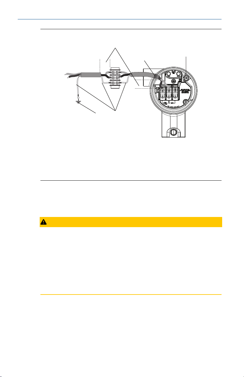
Figure 2-6: Wiring Considerations
Aluminum Polished 316 SST
A. Minimize distance
B. Trim shield and insulate
C. Protective grounding terminal (do not ground cable shield at the
transmitter)
D. Insulate shield
E. Connect shield back to the power supply ground
2.3.1 Grounding for transient terminal block
Ground termination is provided on the outside of the electronics housing
and inside the terminal compartment. These grounds are used when the
transient protection terminal blocks are installed. It is recommended that 18
AWG or larger wire is used to connect housing ground to earth ground
(internal or external).
If the transmitter is currently not wired for power up and communication,
follow Connect the wiring and power up. When the transmitter is properly
wired, refer to Figure 2-6 for internal and external transient grounding
locations.
Note
The Rosemount 3051HT polished 316 SST housing only provides ground
termination inside the terminal compartment.
10 Emerson.com/Rosemount

June 2020 Quick Start Guide
2.4 Verify configuration
Verify the configuration using any HART-capable configuration tool or Local
Operator Interface (LOI) - option code M4. Configuration instructions for a
Field Communicator and LOI are included in this step.
2.4.1 Verifying configuration with a Field Communicator
A Rosemount 3051 DD must be installed on the Field Communicator to
verify configuration. Fast Key sequences for the latest DD are shown in Table
2-1. For Fast Key sequences using legacy DD's, contact your local Emerson
representative.
Note
Emerson recommends installing the latest DD to access the complete
functionality. Visit Emerson.com/Field-Communicator for information on
updating the DD Library.
Procedure
Verify device configuration using the Fast Key sequences in Table 2-1.
• A check (✓) indicates the basic configuration parameters. At minimum,
these parameters should be verified as part of configuration and startup.
Table 2-1: Device Revision 9 and 10 (HART7), DD Revision 1 Fast Key
Sequence
Function Fast Key Sequence
HART 7 HART 5
✓ Alarm and Saturation Levels 2, 2, 2, 5, 7 2, 2, 2, 5, 7
✓ Damping 2, 2, 1, 1, 5 2, 2, 1, 1, 5
✓ Range Values 2, 2, 2 2, 2, 2
✓ Tag 2, 2, 7, 1, 1 2, 2, 7, 1, 1
✓ Transfer Function 2, 2, 1, 1, 6 2, 2, 1, 1, 6
✓ Units 2, 2, 1, 1, 4 2, 2, 1, 1, 4
Burst Mode 2, 2, 5, 3 2, 2, 5, 3
Custom Display Configuration 2, 2, 4 2, 2, 4
Date 2, 2, 7, 1, 4 2, 2, 7, 1, 3
Descriptor 2, 2, 7, 1, 5 2, 2, 7, 1, 4
Digital to Analog Trim (4–20 mA Output) 3, 4, 2 3, 4, 2
Disable Configuration Buttons 2, 2, 6, 3 2, 2, 6, 3
Rerange with Keypad 2, 2, 2, 1 2, 2, 2, 1
Quick Start Guide 11

Quick Start Guide June 2020
Table 2-1: Device Revision 9 and 10 (HART7), DD Revision 1 Fast Key
Sequence (continued)
Function Fast Key Sequence
HART 7 HART 5
Loop Test 3, 5, 1 3, 5, 1
Lower Sensor Trim 3, 4, 1, 2 3, 4, 1, 2
Message 2, 2, 7, 1, 6 2, 2, 7, 1, 5
Scaled D/A Trim (4–20 mA Output) 3, 4, 2 3, 4, 2
Sensor Temperature/Trend (3051S) 3, 3, 3 3, 3, 3
Upper Sensor Trim 3, 4, 1, 1 3, 4, 1, 1
Digital Zero Trim 3, 4, 1, 3 3, 4, 1, 3
Password 2, 2, 6, 5 2, 2, 6, 4
Scaled Variable 3, 2, 2 3, 2, 2
HART Revision 5 to HART Revision 7 switch 2, 2, 5, 2, 3 2, 2, 5, 2, 3
Long Tag
Find Device
Simulate Digital Signal
(1)
(1)
(1)
2, 2, 7, 1, 2 N/A
3, 4, 5 N/A
3, 4, 5 N/A
(1) Only available in HART Revision 7 mode.
2.4.2 Verifying configuration with LOI
The optional LOI can be used for commissioning the device. The LOI is a twobutton design with internal and external/rear buttons. On a polished
stainless steel housing, buttons are located internally both on the display
and terminal side of the transmitter. On an aluminum housing, buttons are
located on the display and externally underneath the top metal tag. To
activate the LOI, push any button. LOI button functionality is shown on the
bottom corners of the display. See Table 2-2 and Figure 2-7 for button
operation and menu information.
12 Emerson.com/Rosemount

Assign PV
HART Revision
June 2020 Quick Start Guide
Table 2-2: LOI Button Operation
Button
Left No SCROLL
Right Yes ENTER
Figure 2-7: LOI Menu
2.4.3 Switch HART Revision mode
If the HART configuration tool is not capable of communicating with HART
Revision 7, the Rosemount 3051 will load a generic menu with limited
capability. The following procedures will switch the HART Revision mode
from the generic menu:
Procedure
Select Manual Setup → Device Information → Identification → Message.
a) To change to HART Revision 5, Enter: HART5 in the Message field.
b) To change to HART Revision 7, Enter: HART7 in the Message field.
Quick Start Guide 13

Quick Start Guide June 2020
Note
See Table 2-1 to change HART Revision when the correct device driver is
loaded.
2.5 Trim the transmitter
Devices are calibrated by the factory. Once installed, it is recommended to
perform a zero trim on gage transmitter to eliminate error due to mounting
position or static pressure effects. A zero trim can be performed using either
a Field Communicator or configuration buttons.
Note
When performing a zero trim, ensure the equalization valve is open and all
wet legs are filled to the correct level.
CAUTION
It is not recommended to zero an absolute transmitter, Rosemount
3051HTA model.
Procedure
Choose your trim procedure.
a) Analog zero trim – Sets the analog output to 4 mA.
• Also referred to as a “rerange” it sets the lower range value (LRV)
equal to the measured pressure.
• The display and digital HART output remains unchanged.
b) Digital zero trim – Recalibrates the sensor zero.
• The LRV is unaffected. The pressure value will be zero (on display
and HART output). 4 mA point may not be at zero.
• This requires the factory calibrated zero pressure is within a range
of 3% of the URL [0 ± 3% × URL].
URV = 250 inH2O
Applied Zero Pressure = ± 0.03 × 250 inH2O = ± 7.5 inH2O (compared to
factory settings) values outside this range will be rejected by the transmitter
2.5.1 Trimming with a Field Communicator
Procedure
1. Connect the Field Communicator, see Connect the wiring and power
up for instructions.
2. Follow the HART menu to perform the desired zero trim.
14 Emerson.com/Rosemount

June 2020 Quick Start Guide
Table 2-3: Zero Trim Fast Keys
Analog Zero (Set 4 mA) Digital Zero
Fast Key sequence 3, 4, 2 3, 4, 1, 3
2.5.2 Trimming with configuration buttons
A zero trim is to be performed using one of the three possible sets of
configuration buttons located above the terminal block or under the top
tag.
To access the configuration buttons on a polished stainless steel housing,
remove the terminal side housing cover.
To access the configuration buttons on an aluminum housing, loosen the
screw on the top tag and slide the tag on the top of the transmitter.
Figure 2-8: External or Rear/Terminal-Side Configuration Buttons for
Aluminum
LOI Analog zero and
span
A. Configuration buttons
Digital zero Aluminum
Quick Start Guide 15

Quick Start Guide June 2020
Figure 2-9: External or Rear/Terminal-Side Configuration Buttons for
Polished 316 SST
LOI Analog zero and
(1)
N/A
(1) LOI buttons (option M4) only offer front facing buttons on SST housing (option
1). Options D4 and DZ can still be purchased for rear/terminal-side facing
buttons.
span
Digital zero
Aluminum
A. Configuration buttons
Perform trim with LOI (option M4)
Procedure
1. Set the transmitter pressure.
2. See Figure 2-7 for the operating menu.
a) Perform an analog zero trim by selecting Rerange.
b) Perform a digital zero trim by selecting Zero Trim.
Perform trim with analog zero and span (option D4)
Procedure
1. Set the transmitter pressure.
2. Press and hold the Zero button for two seconds to perform an analog
zero trim.
16 Emerson.com/Rosemount

June 2020 Quick Start Guide
Perform trim with digital zero (option DZ)
Procedure
1. Set the transmitter pressure.
2. Press and hold the Zero button for two seconds to perform a digital
zero trim.
Quick Start Guide 17

Quick Start Guide June 2020
3 Product certifications
Rev. 1.6
3.1 European Directive Information
A copy of the EU Declaration of Conformity can be found at the end of the
Quick Start Guide. The most recent revision of the EU Declaration of
Conformity can be found at Emerson.com.
3.2 Ordinary Location Certification
As standard, the transmitter has been examined and tested to determine
that the design meets the basic electrical, mechanical, and fire protection
requirements by a nationally recognized test laboratory (NRTL) as accredited
by the Federal Occupational Safety and Health Administration (OSHA).
Altitude Pollution degree
5000 m max 4 (metallic enclosure)
2 (non-metallic enclosure)
3.3 Installing Equipment in North America
The US National Electrical Code® (NEC) and the Canadian Electrical Code
(CEC) permit the use of Division marked equipment in Zones and Zone
marked equipment in Divisions. The markings must be suitable for the area
classification, gas, and temperature class. This information is clearly defined
in the respective codes.
3.4
USA
I5 Intrinsic Safety; Nonincendive
Certificate:
Standards:
Markings:
1053834
FM Class 3600 – 2011, FM Class 3610 – 2010, FM Class 3611
– 2004, FM Class 3810 – 2005
IS CL I, DIV 1, GP A, B, C, D when connected per Rosemount
drawing 03031-1024, CL I ZONE 0 AEx ia IIC T4; NI CL 1, DIV 2,
GP A, B, C, D T5; T4 (–20 °C ≤ Ta ≤ +70 °C) [HART]; T4(–20 °C ≤
Ta ≤ +60 °C) [Fieldbus]; Type 4x
3.5 Canada
I6 Intrinsic Safety
Certificate:
18 Emerson.com/Rosemount
1053834

June 2020 Quick Start Guide
Standards:
Markings:
3.6 Europe
I1 ATEX Intrinsic Safety
Certificate:
Standards:
Markings:
Table 3-1: Input Parameters
Parameter HART Fieldbus/
Voltage U
Current I
Power P
Capacitance Ci0.012 µF 0 µF
Inductance Li0 mH 0 mH
ANSI/ISA 12.27.01-2003, CSA Std. C22.2 No.142-M1987, CSA
Std. C22.2. No.157-92, CSA Std. C22.2 No. 213 - M1987
Intrinsically Safe Class I, Division 1 Groups A, B, C, D when
connected in accordance with Rosemount drawing
03031-1024, Temperature Code T4; Suitable for Class I, Zone
0; Type 4X; Factory Sealed; Single Seal (See drawing
03031-1053)
BAS97ATEX1089X
EN 60079-0:2012 + A11:2013, EN 60079-11:2012
HART™: II 1 G Ex ia IIC T5/T4 Ga, T5(–20 °C ≤ Ta ≤ +40 °C),
T4(–20 °C ≤ Ta ≤ +70 °C) Fieldbus: II 1 G Ex ia IIC Ga T4(–20
°C ≤ Ta ≤ +60 °C)
PROFIBUS
30 V 30 V
i
i
i
200 mA 300 mA
0.9 W 1.3 W
®
Special Conditions for Safe Use (X):
1. The apparatus is not capable of withstanding the 500 V insulation
test required by clause 6.3.12 of EN60079-11:2012. This must be
taken into account when installing the apparatus.
2. The enclosure may be made of aluminum alloy and given a protective
polyurethane paint finish; however care should be taken to protect it
from impact or abrasion if located in Zone 0.
3.7
International
I7 IECEx Intrinsic Safety
Certificate:
Standards:
Quick Start Guide 19
IECEx BAS 09.0076X
IEC 60079-0:2011, IEC 60079-11:2011

Quick Start Guide June 2020
Markings:
Parameter PROFIBUS
Voltage U
Current I
Power P
Capacitance Ci0 µF
Inductance Li0 mH
Special Conditions for Safe Use (X):
1. The apparatus is not capable of withstanding the 500 V insulation
2. The enclosure may be made of aluminum alloy and given a protective
3.8 Brazil
I2 INMETRO Intrinsic Safety
HART™: Ex ia IIC T5/T4 Ga, T5(–20 °C ≤ Ta ≤ +40 °C), T4(–20 °C
≤ Ta ≤ +70 °C)
PROFIBUS®: Ex ia IIC T4 (–20 °C ≤ Ta ≤ +60 °C)
30 V
i
i
i
300 mA
1.3 W
test required by clause 6.3.12 of EN60079-11:2012. This must be
taken into account when installing the apparatus.
polyurethane paint finish; however care should be taken to protect it
from impact or abrasion if located in Zone 0.
Certificate:
Standards:
UL-BR 13.0584X
ABNT NBR IEC60079-0:2008 + Errata 1:2011, ABNT NBR
IEC60079-11:2009
Markings:
HART™: Ex ia IIC T5/T4 Ga, T5(–20 °C ≤ Ta ≤ +40 °C), T4(–20 °C
≤ Ta ≤ +70 °C) Fieldbus: Ex ia IIC T4 Ga (–20 °C ≤ Ta ≤ +60 °C)
HART PROFIBUS
Voltage U
Current I
Power P
Capacitance Ci0.012 µF 0 µF
Inductance L
i
i
i
30 V 30 V
200 mA 300 mA
0.9 W 1.3 W
0 mH 0 mH
i
®
Special Conditions for Safe Use (X):
1. If the equipment is fitted with an optional 90 V transient suppressor,
it is not capable of withstanding the 500 V insulation test required by
20 Emerson.com/Rosemount

June 2020 Quick Start Guide
ABNT NBR IRC 60079-11. This must be taken into account when
installing the equipment.
2. The enclosure may be made of aluminum alloy and given protective
polyurethane paint finish; however, care should be taken to protect it
from impact or abrasion if equipment requires EPL Ga.
3.9 Additional certifications
®
3-A
All Rosemount 3051HT transmitters with the following connections are 3-A
approved and labeled:
T32: 1½-in. Tri Clamp
T42: 2-in. Tri Clamp
If process connection B11 is selected, see reference the ordering table of the
Rosemount 1199 Diaphragm Seal PDS (00813-0100-4016) for availability of
3-A certifications.
A 3-A certificate of compliance is available by selecting option code QA.
EHEDG
All Rosemount 3051HT transmitters with the following connections are
EHEDG approved and labeled:
T32: 1½-in. Tri Clamp
T42: 2-in. Tri Clamp
If process connection B11 is selected, see reference the ordering table of the
Rosemount 1199 Diaphragm Seal PDS (00813-0100-4016) for availability of
EHEDG certifications.
An EHEDG certificate of compliance is available by selecting option code QE.
Ensure gasket selected for installation is approved to meet both application
and EHEDG certification requirements.
ASME-BPE
All Rosemount 3051HT Transmitters with option F2 and the following
connections are designed to ASME-BPE SF4 standards
(1)
:
T32: 1½-in. Tri Clamp
T42: 2-in. Tri Clamp
A self-certified certificate of compliance to ASME-BPE is also available
(option QB)
(1)
Per Clause SD-2.4.4.2 (m), suitability of painted aluminum housings to be
determined by end user.
Quick Start Guide 21

Quick Start Guide June 2020
Figure 3-1: Rosemount 3051HT Declaration of Conformity
22 Emerson.com/Rosemount

June 2020 Quick Start Guide
Figure 3-2: Rosemount 3051HT Declaration of Conformity
Quick Start Guide 23

Quick Start Guide June 2020
Figure 3-3: Rosemount 3051HT Declaration of Conformity
24 Emerson.com/Rosemount

June 2020 Quick Start Guide
China RoHS
Quick Start Guide 25

Quick Start Guide June 2020
26 Emerson.com/Rosemount

June 2020 Quick Start Guide
Quick Start Guide 27

*00825-0100-4091*
00825-0100-4091, Rev. DA
Quick Start Guide
June 2020
Global Headquarters
Emerson Automation Solutions
6021 Innovation Blvd.
Shakopee, MN 55379, USA
+1 800 999 9307 or +1 952 906 8888
+1 952 204 8889
RFQ.RMD-RCC@Emerson.com
Latin America Regional Office
Emerson Automation Solutions
1300 Concord Terrace, Suite 400
Sunrise, FL 33323, USA
+1 954 846 5030
+1 954 846 5121
RFQ.RMD-RCC@Emerson.com
Asia Pacific Regional Office
Emerson Automation Solutions
1 Pandan Crescent
Singapore 128461
+65 6777 8211
+65 6777 0947
Enquiries@AP.Emerson.com
North America Regional Office
Emerson Automation Solutions
8200 Market Blvd.
Chanhassen, MN 55317, USA
+1 800 999 9307 or +1 952 906 8888
+1 952 204 8889
RMT-NA.RCCRFQ@Emerson.com
Europe Regional Office
Emerson Automation Solutions Europe
GmbH
Neuhofstrasse 19a P.O. Box 1046
CH 6340 Baar
Switzerland
+41 (0) 41 768 6111
+41 (0) 41 768 6300
RFQ.RMD-RCC@Emerson.com
Middle East and Africa Regional Office
Emerson Automation Solutions
Emerson FZE P.O. Box 17033
Jebel Ali Free Zone - South 2
Dubai, United Arab Emirates
+971 4 8118100
+971 4 8865465
RFQ.RMTMEA@Emerson.com
Linkedin.com/company/Emerson-
Automation-Solutions
Twitter.com/Rosemount_News
Facebook.com/Rosemount
Youtube.com/user/
RosemountMeasurement
©
2020 Emerson. All rights reserved.
Emerson Terms and Conditions of Sale are
available upon request. The Emerson logo is a
trademark and service mark of Emerson Electric
Co. Rosemount is a mark of one of the Emerson
family of companies. All other marks are the
property of their respective owners.
Loading...