

Page 1
Product Data Sheet
00813-0500-2654, Rev EB
Rosemount™ 214C Temperature Sensors
March 2019
Primary product benefits
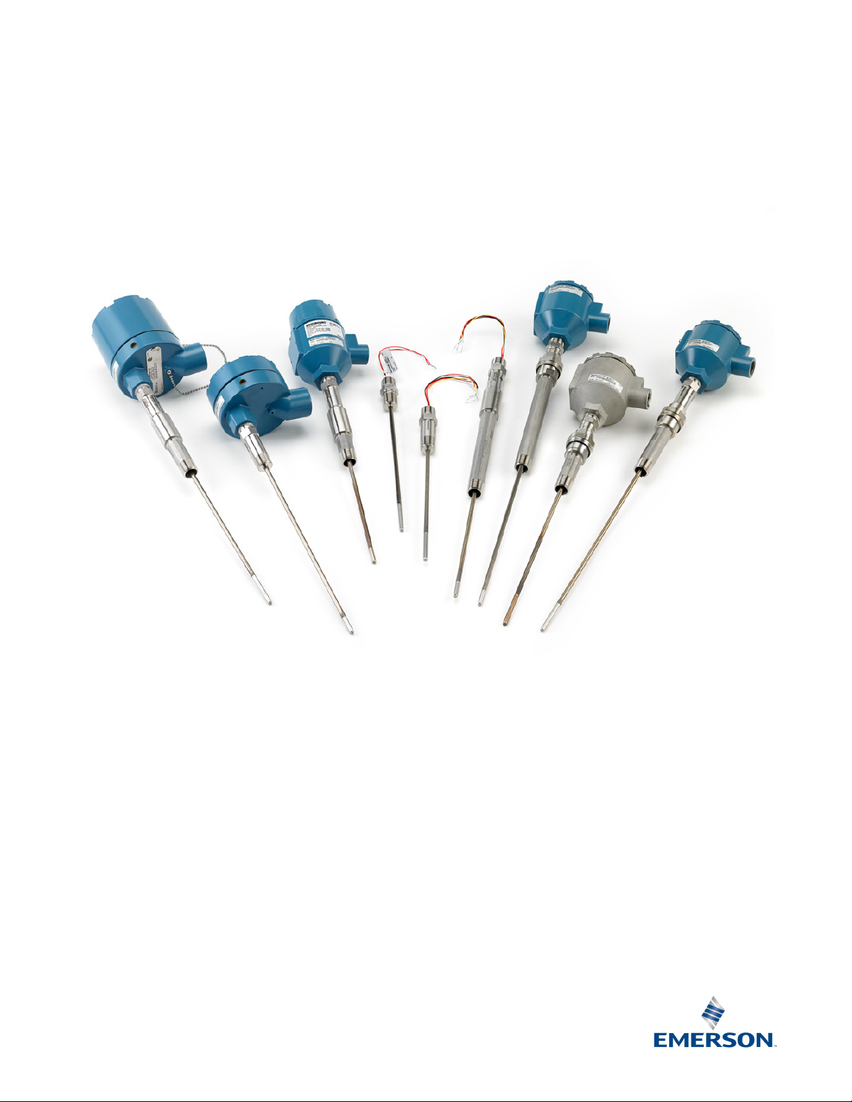
High accuracy resistance temperature detectors (RTD) and various thermocouple types offered in a
variety of element configurations
Calibration capabilities for increased measurement accuracy for RTDs
Page 2

Rosemount 214C
March 2019
Rosemount™ 214C Temperature Sensors
Optimize plant efficiency and increase measurement reliability with industry-proven design and specifications
All sensor styles and lengths available as standard in
State-of-the-art manufacturing processes providing robust element packaging, increasing reliability
Industry-leading calibration capabilities allowing for Callendar-Van Dusen values giving increased RTD accuracy when paired with
Rosemount transmitters
Optional Class A accuracy RTDs or Class 1/Special Tolerances thermocouples for critical temperature measurement points
Explore the benefits of a Complete Point Solution™ from Emerson™
“Transmitter assembled to sensor” and “Thermowell
assembled to sensor” options enable Emerson to provide a
complete point temperature solution, delivering
process-ready or hand-tight transmitter, sensor, and/or
thermowell assemblies
Complete portfolio of Single Point and Multi-Input
Temperature Measurement solutions, allowing effective
measurement and processes control with the trusted
reliability from Rosemount products
1
/4-in. (6 mm) nominal diameter
Experience global consistency and local support from numerous worldwide Emerson manufacturing sites
World-class manufacturing provides globally consistent product from every factory
and the capacity to fulfill needs of any project, large or small
Experienced Instrumentation Consultants help select the right product for any
temperature application and offer advice on best installation practices
Extensive global network of Emerson service and support personnel can be on-site
when and where they are needed
Contents
Rosemount 214C Sensor . . . . . . . . . . . . . . . . . . . . . . . . . . . 3
RTD ordering information . . . . . . . . . . . . . . . . . . . . . . . . . . 4
Thermocouple ordering information . . . . . . . . . . . . . . . 12
Product certifications . . . . . . . . . . . . . . . . . . . . . . . . . . . . .31
Additional RTD specifications . . . . . . . . . . . . . . . . . . . . . . 46
Additional thermocouple specifications . . . . . . . . . . . . .47
Ordering information detail . . . . . . . . . . . . . . . . . . . . . . . 20
2
Emerson.com/Rosemount
Page 3

March 2019
UH
L
Rosemount 214C
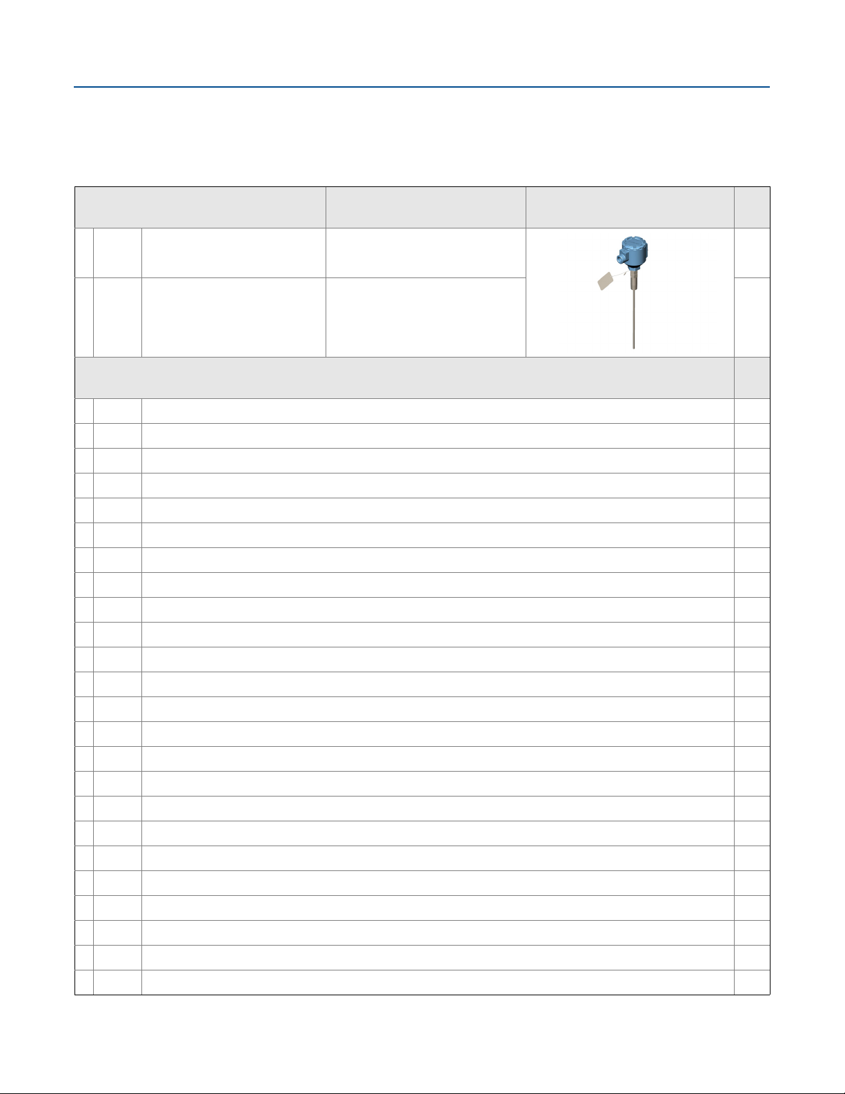
Rosemount 214C Sensor
The Rosemount 214C Sensors are designed to provide flexible and reliable temperature measurements in process monitoring and
control environments.
Features include:
Temperature ranges of –196 to 600 °C (–321 to 1112 °F) for RTDs and –196 to 1200 °C (–321 to 2192 °F) for thermocouples
Industry-standard sensor types: PT100 RTDs; thermocouple Type J, Type K, and Type T
Spring-loaded and compact spring-loaded sensor mounting styles
Hazardous location product approvals and certification
Calibration services to give insight to sensor performance
Calibration certificate to accompany sensor
Specification and selection of product materials, options, or components must be made by the purchaser of the equipment.
Figure 1. Model Number Ordering Example
Model
214C RW SM A1 S 4 E 0150 S L WR5, E5...
1234 56 78 910 1112 13 14151617 1819 X X X X X
Sensor
type
Sheath
material
Sensor
accuracy
Number of
elements
Units
Sensor insertion
length
Sensor
mounting
style
Options
The numbers below the model string example in Figure 1 correlate to the character place numbers in the ordering table.
Ensure sensor fits thermowell
Rosemount 114C Head length (H) + Immersion length (U) = Rosemount 214C Sensor insertion length (L).
Emerson.com/Rosemount
3
Page 4

Rosemount 214C
Quick Order Table - RTD
Sheath material
321 SSTSM
Number of elements
Sensor insertion length
0 to 78.5 inches;
¼-in. increments;
w/ English units
Example
3.5 in = 0035;
50 in = 0500
xxxx
0 to 2000 mm;
5mm increments;
w/ Metric units
Example
125 mm = 0125;
1300 mm = 1300
xxxx
Sensor type
Thin- lm; PT100;
-50 to 450 °C
(-58 to 842 °F)
Thin-lm; PT100
-60 to 600 °C
(-76 to 1112 °F)
T
H
Sensor accuracy
Class A
Class B
A1
B1
units
English/U.S.
customary units
(inches)
Metric units (mm)
E
M
Sensor mounting style
Spring loaded adapter
Adjustable spring
loaded tting
SL
SA
Welded adapterWA
316 SST material options
316 SST ComponentsM2
Product certification
USA Explosionproof
Canada
Explosionproof
E5
E6
See more options in
the full ordering table
xx
Connection heads
Rosemount Aluminum
connection head with
1/2-in. NPT condult
entry and instrument
connection
AR1
C1B1
Extensions types
Union StyleUA
Extension length
xx.x inches, 2.5 to 20
inches in ½-in.
increments; w/ English
xxx mm, 65 to 500 mm
Exxx
Exxx
122
1344C
5R6 7 8 9 10 11 12 13 14 15 16 17 18 19 20...
Dimension
Units
in 5-mm increments;
w/ Metric Units
Single, 3-wireS3
Single, 4 -wireS4
D3 Dual, 3-wire
Wire wound; PT100;
-196 300 °C
(-321 572 °F)
W
to
to
ααα
RTD ordering information
Table 1. Rosemount 214C RTD Quick Order Table
March 2019
Table 2. Rosemount 214C RTD Ordering Information
The starred offerings (★) represent the most common options and should be selected for best delivery. The non-starred offerings are subject
to additional delivery lead time.
Place #s
★
Place #s
★
★
★
Place #s
★
4
1
–4
Model
214C Temperature sensor core base model (made with standard outside diameter of 6 mm [1/4-in.])
5
–6
RT
RW
RH
7-8
SM 321 SST Maximum operating temperature limit of 816 °C (1500 °F) 23
Sensor type Details
RTD, PT100; = 0.00385; –50
to 450 °C (–58 to 842 °F)
RTD, PT100; = 0.00385; –196
to 300 °C (–321 to 572 °F)
RTD, PT100; = 0.00385; –60
to 600 °C (–76 to 1112 °F)
Sensor sheath material Details
Thin-film element is better in vibration and physical shock 21
Wire wound element is better for low temperature applications 21
High temperature thin-film element is better in vibration and physical shock 21
Emerson.com/Rosemount
Ref.
page
Page 5

March 2019
Rosemount 214C
Table 2. Rosemount 214C RTD Ordering Information
The starred offerings (★) represent the most common options and should be selected for best delivery. The non-starred offerings are subject
to additional delivery lead time.
Place #s
9
–10
Sensor accuracy Details
Image
Ref.
page
★
A1
Class A per IEC 60751 over
–50 to 300 °C (–58 to 572 °F)
Class A accuracy is only available
with wire-wound element Option
Code: RW
★
B1 Class B per IEC 60751 24
Place #s
11
–12
★
S3 Single, 3-wire Good measurement results 25
★
S4 Single, 4-wire Excellent measurement results 25
Number of elements Details
Image
Red
Red
White
White
24
★
D3 Dual, 3-wire Added measurement redundancy 25
Place #
13
★
E
★
M Metric units (mm) 26
Dimension units Details
English/U.S. customary units
(inches)
Only applies to lengths
Emerson.com/Rosemount
26
5
Page 6

Rosemount 214C
Table 2. Rosemount 214C RTD Ordering Information
The starred offerings (★) represent the most common options and should be selected for best delivery. The non-starred offerings are subject
to additional delivery lead time.
Place #s
14
–17
Sensor insertion length (L)
March 2019
Ref.
page
★
xxxx
★
xxxx
Place #s
18
-19
★
SL Spring loaded adapter
★
SC Compact spring loaded adapter
★
SW
★
WA Welded adapter
★
WC Compact welded adapter
★
SA Adjustable spring loaded fitting
★
CA Compression fitting 1/8-in. NPT
★
CB Compression fitting 1/4-in. NPT
★
CC Compression fitting 1/2-in. NPT
★
CD Compression fitting 3/4-in. NPT
xxx.x inches, 0 to 78.5 inches in 1/4-in. increments (when ordered with Dimension units code E)
Example of a 6.25-in. length where the second decimal is dropped off: 0062
xxxx mm, 0 to 2000 mm in 5 mm increments (when ordered with Dimension units code M)
Example of a 50 mm length: 0050
Sensor mounting style
Spring loaded adapter with
thermowell contact indication
(1)
Details
Ensures sensor contact with
thermowell tip
Non-explosionproof adapter that is
1.17-in. (29.72 mm) shorter than
standard spring loaded adapter
(currently not available with
Division 2/Zone 2 approvals)
Spring loaded adapter with a small
opening on the side of the adapter
for visual indication of sensor
contact with the tip of a thermowell
Welded joint between sensor
capsule and adapter allows for
direct immersion of sensor into the
process. If thermowell is used, this
welded joint acts as a secondary
process seal.
Non-explosionproof adapter that is
1.17-in. (29.72 mm) shorter than
standard welded adapter (currently
not available with Division 2/Zone 2
approvals)
Adjustable fitting that allows for
installation along sensor capsule
body. The spring loaded fitting
ensures sensor contact to
thermowell tip.
Adjustable fitting that allows for
installation along the sensor
capsule body. (100 psig maximum.)
(Default compression fitting
material is brass. For stainless steel,
select the M2 option.)
Image
26
26
Ref.
page
28
28
28
29
29
29
30
★
SO Sensor only
6
Sensor capsule without any fittings
or adapters for mounting
30
Emerson.com/Rosemount
Page 7
March 2019
Rosemount 214C
Table 2. Rosemount 214C RTD Ordering Information
The starred offerings (★) represent the most common options and should be selected for best delivery. The non-starred offerings are subject
to additional delivery lead time.
Options (include with selected model number)
316SST Material options Details
Image
Changes out the original 304SST
★
M1 316SST Wire on tag
wire on tag to a corrosion-resistant
316SST wire on tag
Replaces various components with
★
M2 316SST Components
corrosion-resistant 316SST material
(review reference page for affected
components)
Product certifications
★
E1 ATEX Flamepro of 32
★
I1 ATEX Intrinsic Safety 32
★
N1 ATEX Zone 2 32
★
ND ATEX Dust Ignitionproof 32
★
E2 Brazil Flameproof 34
★
I2 Brazil Intrinsic Safety 34
★
E3 China Flameproof 34
★
I3 China Intrinsic Safety 35
Ref.
page
30
30
Ref.
page
★
N3 China Zone 2 35
★
E5 USA Explosionproof 31
★
N5 USA Division 2 31
★
E6 Canada Explosionproof 31
★
N6 Canada Division 2 31
★
E7 IECEx Flameproof 33
★
I7 IECEx Intrinsic Safety 33
★
N7 IECEx Zone 2 33
★
NK IECEx Dust Ignitionproof 33
★
EM Technical Regulations Customs Union (EAC) Flameproof 36
★
IM Technical Regulations Customs Union (EAC) Intrinsic Safety 36
★
EP Korea Flameproof 36
★
IP Korea Intrinsic Safety 36
★
K1 Combination of ATEX Flameproof, Intrinsic Safety, Zone 2 and Dust Ignitionproof 36
★
K3 Combination of China Flameproof, Intrinsic Safety, Zone 2, and Dust Ignitionproof 36
★
K7 Combination of IECEx Flameproof, Intrinsic Safety, Zone 2, and Dust Ignitionproof 36
Emerson.com/Rosemount
7
Page 8

Rosemount 214C
March 2019
Table 2. Rosemount 214C RTD Ordering Information
The starred offerings (★) represent the most common options and should be selected for best delivery. The non-starred offerings are subject
to additional delivery lead time.
Product certifications
★
KM
★
KP Combination of Korea Flameproof, Intrinsic Safety, and Dust Ignitionproof 36
★
KA Combination of ATEX Flameproof and Canada Explosionproof 36
★
KB Combination of USA and Canada Explosionproof 36
★
KC Combination of ATEX Flameproof and USA Explosionproof 36
★
KD Combination of ATEX Flameproof, USA and Canada Explosionproof 36
★
KE Combination of ATEX and IECEx Flameproof, USA and Canada Explosionproof 36
★
KN Combination of ATEX and IECEx Zone 2, and USA and Canada Division 2 36
Combination of Technical Regulations Customs Union (EAC) Flameproof, Intrinsic Safety, and Dust
Ignitionproof
Ref.
page
36
Connection heads Details
• Conduit connection: 1/2-in. NPT; M20
• Instrument connection:
★
AR1 Rosemount aluminum
★
AR2
★
SR1 Rosemount SST
Rosemount aluminum with
display cover
• Optional terminal block, stainless
steel cover chain, external ground
screw, or low temperature options
also available
• Conduit connection: 1/2-in. NPT; M20
• Instrument connection:
• Optional terminal block, external
ground screw, or low temperature
options also available
• Conduit connection: 1/2-in. NPT; M20
• Instrument connection:
• Optional terminal block, stainless
steel cover chain, external ground
screw, or low temperature options
also available
1
/2-in. NPT
1
/2-in. NPT
1
/2-in. NPT
Image
Ref.
page
37
37
37
★
SR2
★
AT1 Aluminum with terminal strip
Rosemount SST with display
cover
8
• Conduit connection: 1/2-in. NPT; M20
• Instrument connection:
• Optional terminal block, external
ground screw, or low temperature
options also available
• Conduit connection: 3/4-in. NPT
• Instrument connection:
• Optional stainless steel cover chain or
external ground screw available
1
/2-in. NPT
1
/2-in. NPT
37
37
Emerson.com/Rosemount
Page 9

March 2019
Rosemount 214C
Table 2. Rosemount 214C RTD Ordering Information
The starred offerings (★) represent the most common options and should be selected for best delivery. The non-starred offerings are subject
to additional delivery lead time.
Connection heads Details
Image
Ref.
page
★
AT3
★
AJ1
★
AJ2
Aluminum with terminal strip
and extended cover
Universal 3 entry aluminum
junction box
Universal 3 entry aluminum
junction box with display cover
• Conduit connection: 3/4-in. NPT
• Instrument connection:
• Optional stainless steel cover chain or
external ground screw available
• Conduit connection: 1/2-in. NPT or
M20
• Instrument connection
• Optional terminal block, external
ground screw, and stainless steel
cover chain available
• Conduit connection: 1/2-in. NPT or
M20
• Instrument connection
• Optional terminal block, external
ground screw, and stainless steel
cover chain available
Conduit entry (selection required for connection heads)
★
C1
★
C2 M20 ⫻ 1.5
★
C3
1
/2-in. NPT
3
/4-in. NPT
Available for connection head
options AR1, AR2, SR1, and SR2
Available for connection head
options AR1, AR2, SR1, and SR2
Available for connection head
options AT 1 an d AT3
1
/2-in. NPT
1
/2-in. NPT
1
/2-in. NPT
Image
38
38
38
Ref.
page
38
38
38
Instrument connection (selection required for connection heads)
★
B1
1
/2-in. NPT 39
Conduit cable glands
★
GN1 Ex d, standard cable diameter 39
★
GN2 Ex d, thin cable diameter 39
★
GN6 EMV, standard cable diameter 39
Image
Image
Emerson.com/Rosemount
Ref.
page
Ref.
page
9
Page 10

Rosemount 214C
March 2019
Table 2. Rosemount 214C RTD Ordering Information
The starred offerings (★) represent the most common options and should be selected for best delivery. The non-starred offerings are subject
to additional delivery lead time.
★
GP1 Ex e, standard cable diameter, polyamide 39
★
GP2 Ex e, thin cable diameter, polyamide 39
Extension type Details
Image
Contains union fitting, which allows
★
UA
Union style, 1/2-in. NPT,
1
/2-in. NPT
orientation of the conduit entry
during installation; also known as
nipple-union style
Contains coupling fitting which
★
FA
Fixed style, 1/2-in. NPT,
1
/2-in. NPT
does not allow orientation of the
conduit entry during installation;
also known as nipple-coupling style
Extension length (E)
★
Exxx xx.x inches, 2.5 to 20 inches in 1/2-in. increments (when ordered with Dimension units code E) 40
★
Exxx xxx mm, 65 to 500 mm in 5 mm increments (when ordered with Dimension units code M) 40
Single point calibration
★
X91Q4 Resistance of one specified temperature point 42
Temperature range calibration
★
V20Q4 32 to 212 °F (0 to 100 °C) 43
Ref.
page
40
40
Ref.
page
Ref.
page
Ref.
page
★
V21Q4 32 to 392 °F (0 to 200 °C) 43
★
V22Q4 32 to 842 °F (0 to 450 °C) 43
★
V23Q4 32 to 1112 °F (0 to 600 °C) 43
★
V24Q4 –58 to 212 °F (–50 to 100 °C) 43
★
V25Q4 –58 to 392 °F (–50 to 200 °C) 43
★
V26Q4 –58 to 842 °F (–50 to 450 °C) 43
★
V27Q4 –76 to 1112 °F (–60 to 600 °C) 43
★
X8Q4 Custom specified temperature range 43
Ground screw Details
★
G1 External ground screw
Allows for grounding of wires to the
connection head
10
Image
Emerson.com/Rosemount
Ref.
page
44
Page 11

March 2019
Table 2. Rosemount 214C RTD Ordering Information
The starred offerings (★) represent the most common options and should be selected for best delivery. The non-starred offerings are subject
to additional delivery lead time.
Cover chain Details
Keeps the cover connected to the
★
G3 Cover chain
connection head when
disassembled; not available with
display covers
Rosemount 214C
Image
Ref.
page
44
Terminal block Details
★
TB Terminal block
Available if wire termination in a
connection head is required
Image
Low temperature housing
★
LT Low temperature connection head option down to –51 °C (–60 °F) 44
Transmitter assembled to sensor Details
★
XA
★
XC
Process-ready assembly of
transmitter and sensor
Hand-tight assembly of
transmitter and sensor
Ensures sensor is threaded into connection head with transmitter and
torqued for process-ready installation; sensor is wired to the transmitter
Ensures sensor is threaded into connection head with transmitter but only
hand tightened; manual wiring is required
Thermowell assembled to sensor Details
★
XW
★
XT
Process-ready assembly of
sensor and thermowell
Hand-tight assembly of sensor
and thermowell
Ensures sensor is threaded into thermowell and torqued for process-ready
installation
Ensures sensor is threaded into thermowell but only hand tightened 45
Extended product warranty Details
Ref.
page
44
Ref.
page
Ref.
page
45
45
Ref.
page
45
Ref.
page
★
WR3 3-year limited warranty
★
WR5 5-year limited warranty 45
1. Welded adapters are built several millimeters shorter than specified length to ensure that the sheath will not be damaged by contact with the bottom of a
thermowell if overtightened. Conversely, spring loaded adapters are built several millimeters longer than specified to ensure contact with the bottom of a
thermowell.
This warranty option is to extend your manufacturers warranty to three or
five years for manufacturer related defects
Emerson.com/Rosemount
45
11
Page 12

Rosemount 214C
Sheath material
321 SSTSM
Number of elements
Single, grounded
Single, ungrounded
SG
SU
Sensor insertion length
0 to 78.5 inches;
¼-in. increments;
w/ English units
Example
3.5 in = 0035;
50 in = 0500;
xxxx
0 to 2000 mm;
5 mm increments;
w/ Metric units
Example
125 mm = 0125;
1300 mm = 1300
xxxx
Sensor type
Thermocouple Type J
-40 to 760 °C
(-40 to 1400 °F)
Thermocouple Type K
-40 to 1200 °C
(-40 to 2192 °F)
J
K
Sensor accuracy
Class 1
Class 2
T1
T2
units
English/U.S.
customary units
(inches)
Metric units (mm)
E
M
Sensor mounting style
Spring loaded adapter
Adjustable spring
loaded tting
SL
SA
Welded adapterWA
12213
44C
5T6 7 8 9 10 11 12 13 14 15 16 17 18 19 20...
Thermocouple Type T
-196 to 370 °C
(-321 to 698 °F)
T
Alloy 600 (Type K
only)
AK
Special Tolerances
Standard Tolerances
SP
ST
Dual, grounded,
un-isolated
Dual, ungrounded,
isolated
DG
DU
316 SST material options
316 SST ComponentsM2
Product certification
USA Explosionproof
Canada
Explosionproof
E5
E6
See more options in
the full ordering table
xx
Connection heads
Rosemount Aluminum
connection head with
1/2-in. NPT condult
entry and instrument
connection
AR1
C1B1
Extensions types
Union StyleUA
Extension length
xx.x inches, 2.5 to 20
inches in ½-in.
increments; w/ English
xxx mm, 65 to 500
mm in 5-mm
increments; w/ Metric
Exxx
Exxx
Dimension
units
units
Thermocouple ordering information
Table 3. Rosemount 214C Thermocouple Quick Order Table
March 2019
Table 4. Rosemount 214C Thermocouple Ordering Information
The starred offerings (★) represent the most common options and should be selected for best delivery. The non-starred offerings are subject
to additional delivery lead time.
12
Place #s
1
–4
★
214C Temperature thermocouple sensor core base model (made with standard outside diameter of 6mm [1/4-in.])
Place #s
5
–6
★
TJ
★
TK
★
TT
Model
Sensor type Details
Thermocouple Type J,
–40 to 760 °C (–40 to 1400 °F)
Thermocouple Type K,
–40 to 1200 °C (–40 to 2192 °F)
Thermocouple Type T,
–196 to 370 °C (–321 to 698 °F)
One of the most common thermocouples made of conductor materials Iron and
Constantan
Commonly used for high temperature applications, Type K thermocouples
contain Chromel® and Alumel® conductors (available with sheath material
Option AK only)
Commonly used for low temperature applications, Type T thermocouples
contain copper and constantan conductors
Emerson.com/Rosemount
Ref.
page
22
23
23
Page 13

March 2019
Table 4. Rosemount 214C Thermocouple Ordering Information
The starred offerings (★) represent the most common options and should be selected for best delivery. The non-starred offerings are subject
to additional delivery lead time.
Place #s
7
–8
★
SM 321 SST
★
AK
Sensor sheath material Details
Maximum operating temperature limit of 816 °C (1500 °F) (For types TJ and TT
only)
(1)
Alloy 600 Maximum operating temperature limit of 1200 °C (2192 °F) (For type TK only) 24
Rosemount 214C
Ref.
page
23
Place #s
9
–10
★
T1 Class 1 per IEC 60584
★
T2 Class 2 per IEC 60584
★
SP
★
ST
Place #s
11
–12
★
SG Single, grounded
★
SU Single, ungrounded
Sensor accuracy Details
Special Tolerances per ASTM
E230
Standard Tolerances per ASTM
E230
Number of elements Details
Approximately half of accuracy error margin than Class 2; made with higher
grade wire which increases accuracy reading
Wider accuracy error margin than Class 1; made with standard thermocouple
grade wire
Approximately half of accuracy error margin than Standard Tolerances; made
with higher grade wire which increases the accuracy reading
Wider accuracy error margin than Special Tolerances; made with standard
thermocouple grade wire
Image
Provides contact to sheath for faster
response time than a single,
ungrounded thermocouple; more
susceptible to induced noise from
ground loops
Provides more accurate reading than a
single grounded thermocouple, with a
slower response time
Ref.
page
25
25
25
25
Ref.
page
26
26
Provides faster response time than a
★
DG Dual, grounded, unisolated
★
DU Dual, ungrounded, isolated
Place #
13
★
E
★
M Metric units (mm) 26
Dimension units Details
English/U.S. customary units
(inches)
dual ungrounded isolated
thermocouple with added
redundancy in the reading
Provides more accurate reading than a
dual grounded unisolated
thermocouple, with a slower response
time
Only applies to lengths
Emerson.com/Rosemount
26
26
Ref.
page
26
13
Page 14

Rosemount 214C
March 2019
Table 4. Rosemount 214C Thermocouple Ordering Information
The starred offerings (★) represent the most common options and should be selected for best delivery. The non-starred offerings are subject
to additional delivery lead time.
Place #s
14-17
Sensor insertion length (L)
Ref.
page
★
xxxx
Example of a 6.25-in. length where the second decimal is dropped off: 0062
xxxx mm, 0 to 2000 mm in 5 mm increments (when ordered with Dimension units code M)
xxx.x-in. 0 to 78.5-in. in 1/4-in. increments (when ordered with Dimension units code E)
★
xxxx
Example of a 50 mm length: 0050
Place #s
18
–19
★
SL Spring loaded adapter
★
SC Compact spring loaded adapter
★
SW
★
WA Welded adapter
★
WC Compact welded adapter
★
SA Adjustable spring loaded fitting
★
CA Compression fitting 1/8-in. NPT
★
CB Compression fitting 1/4-in. NPT
★
CC Compression fitting 1/2-in. NPT
★
CD Compression fitting 3/4-in. NPT
Sensor mounting style
Spring loaded adapter with
thermowell contact indication
(2)
Details
Ensures sensor contact with
thermowell tip
Non-explosionproof adapter that is
1.17-in. (29.72 mm) shorter than
standard spring loaded adapter
(currently not available with
Division 2/Zone 2 approvals)
Spring loaded adapter with a small
opening on the side of the adapter for
visual indication of sensor contact
with the tip of a thermowell
Welded joint between sensor capsule
and adapter allows for direct
immersion of sensor into the process.
If thermowell is used, this welded joint
acts as a secondary process seal.
Non-explosionproof adapter that is
1.17-in. (29.72 mm) shorter than
standard welded adapter (currently
not available with Division 2/Zone 2
approvals)
Adjustable fitting that allows for
installation along sensor capsule
body. The spring loaded fitting
ensures sensor contact to thermowell
tip.
Adjustable fitting that allows for
installation along the sensor capsule
body.(Default compression fitting
material is brass. For stainless steel,
select the M2 option.) (100 psig
maximum.)
Image
26
26
Ref.
page
28
28
28
29
29
29
30
★
SO Sensor only
14
Sensor capsule without any fittings or
adapters for mounting
30
Emerson.com/Rosemount
Page 15

March 2019
Rosemount 214C
Table 4. Rosemount 214C Thermocouple Ordering Information
The starred offerings (★) represent the most common options and should be selected for best delivery. The non-starred offerings are subject
to additional delivery lead time.
Options (include with selected model number)
316SST Material options Details
Image
Changes out the original 304SST wire
★
M1 316SST Wire on tag
on tag to a corrosion-resistant 316SST
wire on tag
Replaces various components with
★
M2 316SST Components
corrosion-resistant 316SST material
(review reference page for affected
components)
Product certifications
★
E1 ATEX Flamepr oof 32
★
I1 ATEX Intrinsic Safety 32
★
N1 ATEX Zone 2 32
★
ND ATEX Dust Ignitionproof 32
★
E2 Brazil Flameproof 34
★
I2 Brazil Intrinsic Safety 34
★
E3 China Flameproof 34
★
I3 China Intrinsic Safety 35
Ref.
page
30
30
Ref.
page
★
N3 China Zone 2 35
★
E5 USA Explosionproof 31
★
N5 USA Division 2 31
★
E6 Canada Explosionproof 31
★
N6 Canada Division 2 31
★
E7 IECEx Flameproof 33
★
I7 IECEx Intrinsic Safety 33
★
N7 IECEx Zone 2 33
★
NK IECEx Dust Ignitionproof 33
★
EM Technical Regulations Customs Union (EAC) Flameproof 36
★
IM Technical Regulations Customs Union (EAC) Intrinsic Safety 36
★
EP Korea Flameproof 36
★
IP Korea Intrinsic Safety 36
★
K1 Combination of ATEX Flameproof, Intrinsic Safety, Zone 2 and Dust Ignitionproof 36
★
K3 Combination of China Flameproof, Intrinsic Safety, Zone 2, and Dust Ignitionproof 36
★
K7 Combination of IECEx Flameproof, Intrinsic Safety, Zone 2, and Dust Ignitionproof 36
Emerson.com/Rosemount
15
Page 16

Rosemount 214C
March 2019
Table 4. Rosemount 214C Thermocouple Ordering Information
The starred offerings (★) represent the most common options and should be selected for best delivery. The non-starred offerings are subject
to additional delivery lead time.
Product certifications
★
KM Combination of Technical Regulations Customs Union (EAC) Flameproof, Intrinsic Safety, and Dust Ignitionproof 36
★
KP Combination of Korea Flameproof, Intrinsic Safety, and Dust Ignitionproof 36
★
KA Combination of ATEX Flameproof and Canada Explosionproof 36
★
KB Combination of USA and Canada Explosionproof 36
★
KC Combination of ATEX Flameproof and USA Explosionproof 36
★
KD Combination of ATEX Flameproof, USA and Canada Explosionproof 36
★
KE Combination of ATEX and IECEx Flameproof, USA and Canada Explosionproof 36
★
KN Combination of ATEX and IECEx Zone 2, and USA and Canada Division 2 36
Ref.
page
Connection heads Details
• Conduit connection: 1/2-in. NPT; M20
• Instrument connection:
★
AR1 Rosemount aluminum
★
AR2
★
SR1 Rosemount SST
Rosemount aluminum with
display cover
• Optional terminal block, stainless steel
cover chain, external ground screw, or
low temperature options also available
• Conduit connection: 1/2-in. NPT; M20
• Instrument connection:
• Optional terminal block, external
ground screw, or low temperature
options also available
• Conduit connection: 1/2-in. NPT; M20
• Instrument connection:
• Optional terminal block, stainless steel
cover chain, external ground screw, or
low temperature options also available
1
/2-in. NPT
1
/2-in. NPT
1
/2-in. NPT
Image
Ref.
page
37
37
37
★
SR2
★
AT1 Aluminum with terminal strip
Rosemount SST with display
cover
16
• Conduit connection: 1/2-in. NPT; M20
• Instrument connection:
• Optional terminal block, external
ground screw, or low temperature
options also available
• Conduit connection: 3/4-in. NPT
• Instrument connection:
• Optional stainless steel cover chain or
external ground screw available
1
/2-in. NPT
1
/2-in. NPT
37
37
Emerson.com/Rosemount
Page 17

March 2019
Rosemount 214C
Table 4. Rosemount 214C Thermocouple Ordering Information
The starred offerings (★) represent the most common options and should be selected for best delivery. The non-starred offerings are subject
to additional delivery lead time.
Connection heads Details
Image
Ref.
page
★
AT3
★
AJ1
★
AJ2
Aluminum with terminal strip
and extended cover
Universal 3 entry aluminum
junction box
Universal 3 entry aluminum
junction box with display cover
• Conduit connection: 3/4-in. NPT
• Instrument connection:
• Optional stainless steel cover chain or
external ground screw available
• Conduit connection: 1/2-in. NPT or M20
• Instrument connection
• Optional terminal block, external
ground screw, and stainless steel cover
chain available
• Conduit connection: 1/2-in. NPT or M20
• Instrument connection
• Optional terminal block, external
ground screw, and stainless steel cover
chain available
Conduit entry (selection required for connection heads)
★
C1
★
C2 M20 ⫻ 1.5
★
C3
1
/2-in. NPT
3
/4-in. NPT
Available for connection head options
AR1, AR2, SR1, and SR2
Available for connection head options
AR1, AR2, SR1, and SR2
Available for connection head options
AT1 and AT3
1
/2-in. NPT
1
/2-in. NPT
1
/2-in. NPT
Image
38
37
37
Ref.
page
38
38
38
Instrument connection (selection required for connection heads)
★
B1
1
/2-in. NPT 39
Conduit cable glands
★
GN1 Ex d, standard cable diameter 39
★
GN2 Ex d, thin cable diameter 39
★
GN6 EMV, standard cable diameter 39
Image
Image
Emerson.com/Rosemount
Ref.
page
Ref.
page
17
Page 18

Rosemount 214C
Table 4. Rosemount 214C Thermocouple Ordering Information
The starred offerings (★) represent the most common options and should be selected for best delivery. The non-starred offerings are subject
to additional delivery lead time.
Conduit cable glands
★
GP1 Ex e, standard cable diameter, polyamide 39
★
GP2 Ex e, thin cable diameter, polyamide 39
Image
March 2019
Ref.
page
Extension type Details
Contains union fitting which allows
★
UA
★
FA
Union style, 1/2-in. NPT,
1
/2-in. NPT
Fixed style, 1/2-in. NPT,
1
/2-in. NPT
orientation of the conduit entry
during installation; also known as
nipple-union style
Contains coupling fitting which does
not allow orientation of the conduit
entry during installation; also known
as nipple-coupling style
Image
Extension length (E)
★
Exxx xx.x-in., 2.5 to 20-in. in 1/2-in. increments (when ordered with Dimension units code E) 40
★
Exxx xxx mm, 65 to 500 mm in 5 mm increments (when ordered with Dimension units code M) 40
Ground screw Details
★
G1 External ground screw
Allows for grounding of wires to the
connection head
Image
Ref.
page
40
40
Ref.
page
Ref.
page
44
Cover chain Details
Keeps the cover connected to the
★
G3 Cover chain
connection head when disassembled;
not available with display covers
Terminal block Details
★
TB Terminal block
Available if wire termination in a
connection head is required
18
Image
Image
Emerson.com/Rosemount
Ref.
page
44
Ref.
page
44
Page 19

March 2019
Table 4. Rosemount 214C Thermocouple Ordering Information
The starred offerings (★) represent the most common options and should be selected for best delivery. The non-starred offerings are subject
to additional delivery lead time.
Rosemount 214C
Low temperature housing
★
LT Low temperature connection head option down to –51 °C (–60 °F) 44
Ref.
page
Transmitter assembled to sensor Details
★
XA
★
XC
Process-ready assembly of
transmitter and sensor
Hand-tight assembly of
transmitter and sensor
Ensures sensor is threaded into connection head with transmitter and torqued
for process-ready installation; sensor is wired to the transmitter
Ensures sensor is threaded into connection head with transmitter but only hand
tightened; manual wiring is required
Thermowell assembled to sensor Details
★
XW
★
XT
Process-ready assembly of
sensor and thermowell
Hand-tight assembly of sensor
and thermowell
Ensures sensor is threaded into thermowell and torqued for process-ready
installation
Ensures sensor is threaded into thermowell but only hand tightened 45
Extended product warranty Details
★
WR3 3-year limited warranty
★
WR5 5-year limited warranty 45
1. For type TK only.
2. Welded adapters are built several millimeters shorter than specified length to ensure that the sheath will not be damaged by contact with the bottom of a thermowell if
overtightened. Conversely, spring loaded adapters are built several millimeters longer than specified to ensure contact with the bottom of a thermowell.
This warranty option is to extend your manufacturers warranty to three or five
years for manufacturer related defects
Ref.
page
45
45
Ref.
page
45
Ref.
page
45
Emerson.com/Rosemount
19
Page 20

Rosemount 214C
α
March 2019
Ordering information detail
Sensor type
Back to RTD ordering table
Back to Thermocouple ordering table
RTD
RTDs are based on the principle that the electrical resistance of a metal increases as temperature increases – a phenomenon known
as thermal resistivity. Thus, a temperature measurement can be inferred by measuring the resistance of the RTD element.
RTDs are constructed of a resistive material with leads attached and usually placed into a protective sheath (see “Sheath material” on
page 23 for details). The resistive material can be a variety of materials. Emerson however, standardizes on platinum materials for all
RTDs because of its high accuracy, excellent repeatability, and exceptional linearity over a wide temperature range. Platinum RTDs
also exhibit a large resistance change per degree of temperature change.
The relationship between the resistance change of an RTD vs. temperature is called its Temperature Coefficient of Resistance (TCR)
and is often referred to as the RTD's alpha curve. Emerson's PT100 RTDs all have a standard alpha coefficient of
= 0.00385 which is the most popular option that is recognized nationally and internationally. Reference Figure 2 for typical
behavior of the resistance of a platinum RTD over a range of temperature.
Figure 2. Resistance Change vs. Temperature for Platinum RTD (PT100)
Emerson offers the two most common styles of RTD sensors: thin-film and wire-wound. Wire-wound RTDs are manufactured by
winding the resistive wire in a helical shape supported in a ceramic sheath – hence the name wire-wound. Thin-film RTDs are
manufactured with a thin resistive coating that is deposited on a flat, usually rectangular ceramic substrate.
20
Emerson.com/Rosemount
Page 21

March 2019
α
α
Figure 3. RTD Elements
Thin-film RTD (RT, RH)
Rosemount 214C
Thin-film Wire-wound
Thin-film elements are generally better in vibration and physical shock. With a platinum construction (PT100) and a temperature
coefficient =0.00385, these elements can be rated between –60 to 600 °C (–76 to 1112 °F).
Wire-wound RTD (RW)
When a lower temperature range is required for an RTD, the wire-wound element is a better choice. The RW option code is for
wire-wound RTDs which are for –196 to 300 °C (–321 to 572 °F). Similar to the thin-film element, this element has a platinum
construction (PT100) and an alpha value of =0.00385. Because of its lower temperature range, this option should be chosen for
low temperature applications (below
Table 5. RTD Comparison
Option code
Element type
Temperature range
Good for
Accuracy
–60 °C [–76 °F]).
RT RW RH
Thin film Wire wound High temperature thin film
–50 to 450 °C
–58 to 842 °F)
(
Higher vibration and
physical shock
Class B Class A; Class B Class B
–196 to 300 °C
–321 to 572 °F)
(
Higher accuracy and low
temperature applications
–60 to 600 °C
–76 to 1112 °F)
(
Higher temperature
applications, resistance to
vibration, and physical shock
Emerson.com/Rosemount
21
Page 22

Rosemount 214C
Type
Performance Range (°C)
-200
1000
800
600
400
200
0
1200
Type J Thermocouple
Type K Thermocouple
Type T Thermocouple
2200
1800
1400
1000
600
200
-200
Performance Range (°F)
μ
March 2019
Thermocouple
A thermocouple (T/C) is a closed-circuit thermoelectric temperature sensing device consisting of two wires of dissimilar metals
joined at both ends. A current is created when the temperature at one end or junction differs from the temperature at the other end.
This phenomenon is known as the Seebeck effect, which is the basis for thermocouple temperature measurements.
One end is referred to as the hot junction whereas the other end is referred to as the cold junction. The hot junction measuring
element is placed inside a sensor sheath and exposed to the process. The cold junction, or the reference junction, is the termination
point outside of the process where the temperature is known and where the voltage is being measured (e.g. in a transmitter, control
system input card, or other signal conditioner).
According to the Seebeck effect, a voltage measured at the cold junction is proportional to the difference in temperature between
the hot junction and the cold junction. This voltage may be referred to as the Seebeck voltage, thermoelectric voltage, or
thermoelectric EMF. As the temperature rises at the hot junction, the observed voltage at the cold junction also increases
non-linearly with the rising temperature. The linearity of the temperature-voltage relationship depends on the combination of
metals used to make the T/C.
There are many types of T/C that use various metal combinations. These combinations have different output characteristics that
define the applicable temperature range it can measure and the corresponding voltage output. The higher the magnitude of the
voltage output the higher the measurement resolution, which increases repeatability and accuracy. There are trade-offs between
measurement resolutions and temperature ranges which suits individual T/C types to specific ranges and applications. Refer to
Figure 4 for different thermocouple behavior over a range of temperatures.
Figure 4. Thermocouple Temperature Ranges
Emerson offers a variety of thermocouples: Type J, Type K, and Type T.
Type J (TJ)
Figure 5. Type J Thermocouple Colors
Constructed of iron and constantan, Type J thermocouples have a potential temperature range of –40 to 760 °C (–40 to 1400 °F), and
a sensitivity of about 50 V/ °C. Type J thermocouples becomes brittle below 0 °C (32 °F) and are suitable for use in vacuum,
reducing, or inert atmospheres. These thermocouples will have a reduced life if used in an oxidizing atmosphere.
22
ASTM color codes IEC color codes
Emerson.com/Rosemount
Page 23

March 2019
μ
μ
Rosemount 214C
Type K (TK)
Figure 6. Type K Thermocouple Colors
ASTM color codes IEC color codes
Constructed of Chromel and Alumel materials, Type K thermocouples are one of the most common general purpose thermocouples,
have a potential temperature range of
thermocouples are relatively linear and may be used in continuously oxidizing or neutral atmospheres, and are typically used above
538 °C (1000 °F).
–40 to 1200 °C (–40 to 2192 °F), and a sensitivity of approximately 41 V/ °C. Type K
Type T (TT)
Figure 7. Type T Thermocouple Colors
ASTM color codes IEC color codes
Constructed of copper and constantan, Type T thermocouples have a potential temperature range of –196 to 370 °C (–321 to 698 °F)
and a sensitivity of 38 V/ °C. Type T thermocouples demonstrate a good linearity and can be used in oxidizing, reducing or inert
atmospheres, as well as in a vacuum. These thermocouples exhibit a high resistance to moisture corrosion, and are typically used in
very low (cryogenic) to medium temperature ranges.
Table 6. Thermocouple Types
Option code
Element type
Metals
Temperature range
Good for
Medium temperature ranges High temperature ranges Low (cryogenic) temperature ranges
TJ TK TT
Type J Type K Type T
Iron-constantan Chromel-Alumel Copper-constantan
–40 to 760 °C
–40 to 1400 °F)
(
–40 to 1200 °C
–40 to 2192 °F)
(
–196 to 370 °C
–321 to 698 °F)
(
Sheath material
Back to RTD ordering table
Back to Thermocouple ordering table
(SM)
For Type J and T thermocouples, Emerson offers a protective sheath made of 321 SST. This material is a stainless steel stabilized by
adding titanium. This gives it excellent resistance to intergranular corrosion after exposure to high temperatures (above 427 °C [800
°F]). Type 321 has a maximum operating temperature limit of 816 °C (1500 °F). The operating temperature range for the sensor
element will constrain this limit. See Table 5 and Table 6 for the temperature range of the different sensor element types. This
material is only available for Type J and T thermocouple.
Emerson.com/Rosemount
23
Page 24

Rosemount 214C
March 2019
(AK)
For Type K thermocouples, Emerson offers a protective sheath made of Alloy 600. This material is a nickel-chromium alloy with good
oxidation resistance at higher temperatures. Alloy 600 is designed for use in the temperature range of –40 to 1200 °C
(–40 to 2192 °F). The operating temperature range for the sensor element will be constrained by this limit.This material is only
available for Type K thermocouples.
Sensor accuracy
Back to RTD ordering table
Back to Thermocouple ordering table
(A1, B1)
The thin-film option codes RT and RH are available in Class B accuracy only.
The wire-wound option code RW is intended for applications that require high accuracy and/or subjected to low temperatures.
Option code RW is available with both Class A and Class B accuracy over –50 to 300 °C (–58 to 572 °F).
Table 7 shows the interchangeability of RTD sensors. It explains the tolerance for Class A and Class B accuracy RTDs over a specific
temperature range. The performance of the option codes RT and RW sensors conform to the standard set by IEC 60751. Figure 8 is a
graphical representation that demonstrates the Class A and Class B accuracy curve over temperature per IEC 60751. For maximum
system accuracy, Emerson can provide sensor calibration and optional sensor-to-transmitter matching obtainable through the use of
Callendar-Van Dusen constants. See “Calibration” on page 42 for additional calibration offering.
Table 7. Interchangeability Error for RTD per IEC 60751
°C (°F) Tolerance in °C (°F)
Class B for RTD Model
Option RT
-196 (-321) N/A ±1.28 (2.30) N/A N/A
-100 (-148) N/A ±0.8 (1.44) N/A N/A
-50 (-58) ±0.55 (0.99) ±0.55 (0.99) ±0.25 (0.45) ±0.55 (0.99)
0 (32) ±0.3 (0.54) ±0.3 (0.54) ±0.15 (0.27) ±0.3 (0.54)
100 (212) ±0.8 (1.44) ±0.8 (1.44) ±0.35 (0.63) ±0.8 (1.44)
200 (392) ±1.3 (2.34) ±1.3 (2.34) ±0.55 (0.99) ±1.3 (2.34)
300 (572) ±1.8 (3.24) ±1.8 (3.24) ±0.75 (1.35) ±1.8 (3.24)
450 (842) ±2.55 (4.59) N/A N/A ±2.55 (4.59)
500 (932) N/A N/A N/A ±2.8 (5.04)
600 (1112) N/A N/A N/A ±3.3 (5.94)
Figure 8. Sensor Accuracy Curve
Class B for RTD Model
Option RW
Class A for RTD Model
Option RW
Class B for RTD Model
Option RH
24
Emerson.com/Rosemount
Page 25

March 2019
Rosemount 214C
(T1, T2, SP, ST)
Similar to RTDs, thermocouples also can have tolerances as defined by national standards. According to IEC 60584, thermocouples
can have a narrower tolerance (or higher accuracy) of Class 1. Class 1 thermocouples are manufactured with higher grade wire which
increases their accuracy reading. Class 2, on the other hand, has a wider accuracy error margin since they are manufactured with
standard thermocouple grade wires.
Emerson also provides thermocouples that meet tolerances per ASTM E230 standards. Special Tolerances are approximately half of
accuracy error margin than Standard Tolerances since they are made with higher grade wire.
Number of elements
Back to RTD ordering table
Back to Thermocouple ordering table
(S3, S4, D3)
For applications where a generic RTD temperature measurement is sufficient, select option S3 for a single, 3-wire measurement. For
better results, select option S4 for a single, 4-wire measurement. For added measurement reassurance, select option D3 for a dual,
3-wire measurement.
Since the lead wires are part of the RTD circuit, the lead wire resistance needs to be compensated for to achieve the best accuracy.
This becomes especially critical in applications where long sensor and/or lead wires are used. Emerson provides two lead wire
configurations that are commonly available: 3-wire and 4-wire.
In a 4-wire configuration, the lead wire resistance is inconsequential to the measurement. It uses a measurement technique where a
very small constant current of about 150 μA is applied to the sensor through two leads and the voltage developed across the sensor is
measured over the other two wires with a high-impedance and high resolution measuring circuit. In accordance with Ohm’s Law the
high impedance virtually eliminates any current flow in the voltage measurement leads and therefore the resistance of the leads is
not a factor.
In a 3-wire configuration, compensation is accomplished using a third wire with the assumption that it will be the same resistance as
the other two wires and the same compensation is applied to all three wires.
Lead wire configurations can be programmed in Emerson's Rosemount Temperature Transmitters since they are capable of
compensating for the various configurations.
All of the available lead wire configurations conform to IEC 60751. As a result, the wire colors for the sensor match what is defined by
the standard.
A 4-wire sensor can also be used in a 2- or 3- wire configuration. To properly wire the 4-wire RTD for use in a 2-, 3-, or 4-wire
configuration, refer to the Rosemount 214C Quick Start Guide
Figure 9. RTD Lead Wire Configurations
.
Single element, 3-wire (S3) Single element, 4-wire (S4) Dual element, 3-wire (D3)
Red
Red
White
White
Emerson.com/Rosemount
25
Page 26

Rosemount 214C
March 2019
(SG, SU, DG, DU)
For generic thermocouple measurements, select option SG for a single, grounded junction thermocouple measurement. This
grounded configuration provides contact to the sheath for faster response time; however, this is more susceptible to induced noise
from ground loops. This can be avoided by selecting option SU for single, ungrounded thermocouple configuration. This particular
type provides a more accurate reading than a single, grounded thermocouple, but with a slower response time due to it's isolation.
For added redundancy in the temperature measurement, select option DG for dual, grounded, unisolated configuration; or option
DU for dual, ungrounded, isolated sensor wire configuration. See Figure 10 for all available configurations.
Figure 10. Thermocouple Lead Wire Configurations
Single, grounded (SG) Single, ungrounded (SU)
Dual, grounded, unisolated (DG) Dual, ungrounded, isolated (DU)
Dimension units
Back to RTD ordering table
Back to Thermocouple ordering table
These dimensional units determine both the sensor insertion length and the extension length through the model.
English/U.S. customary units (E)
If English/U.S. customary units is selected, then all lengths will be in inches.
Metric (M)
If metric is selected, then all lengths will be in millimeters.
Sensor insertion length
Back to RTD ordering table
Back to Thermocouple ordering table
Sensor insertion length can be ordered by specifying a four-digit option code. However, when ordering, the second decimal place is
dropped off.
When ordering in inches, the length can be ordered in
120.25-in. = 1202
62.75 -in. = 0627
1
/4-in. increments. Here are some examples:
26
Emerson.com/Rosemount
Page 27

March 2019
When ordering in millimeters, the length can be ordered in 5 mm increments. Here are some examples:
50 mm = 0050
325 mm = 0325
Rosemount 214C
Determining the length (L) of a replacement spring-loaded sensor in existing installation
To replace only the sensor
1. Remove the existing sensor from the installation.
2. Measure the sensor length with the spring in the relaxed state from the tip of the sensor to the thread engagement point of
13 mm (0.5-in.) into the adapter threads.
3. Subtract 6 mm (0.25-in.) from your measurement. The resulting length is (L). Use this length to specify the sensor insertion
length in the ordering table.
To replace the sensor and extension
1. Remove the existing sensor and extension from the installed thermowell.
2. Measure the sensor length with the spring in the relaxed state from the tip of the sensor to the thread engagement point of
13 mm (0.5-in.) into the extension threads.
3. Subtract 6 mm (0.25-in.) from your measurement. The resulting length is (L). Use this length to specify the sensor insertion
length in the ordering table.
4. Measure the extension length from thermowell connection to the adapter/fitting connection accounting for 13 mm (0.5-in.)
thread engagement. The resulting length is (E). Use this length to specify the extension length in the ordering table (see
“Extension length” on page 40).
Note
Emerson standardizes on a spring compression of 13 mm (0.5-in.) for all spring loaded and compact spring loaded mounting styles
for sensors. The thermowell tip thickness is assumed to be 6 mm (0.25-in.) and the sensors are built 6 mm (0.25-in.) longer than the
ordered length to ensure contact to the thermowell tip.
To ensure sensor fits the Rosemount 114C Thermowell, refer to “Ensure sensor fits thermowell” on page 3.
Emerson.com/Rosemount
27
Page 28

Rosemount 214C
March 2019
Sensor mounting style
Back to RTD ordering table
Back to Thermocouple ordering table
Emerson offers a variety of mounting style options for every sensor. Depending on the application needs and constraints, a certain
type of mounting style may be preferred. See description of each style and their dimensions below.
Threaded style mounting adapters
The threaded style is a sensor with a threaded adapter to provide a connection to the process and connection head. The benefit of
the threaded style is the ability to install it directly into a process or thermowell without any additional mounting fittings. Emerson
currently offers two different threaded mounting styles: Spring loaded adapter and Compact spring loaded adapter.
Spring loaded adapter (SL)
A spring located in the threaded adapter allows the sensor to travel, ensuring contact with the
bottom of a thermowell. This helps ensure better sensor accuracy, improved sensor response
time and aids in providing better performance while under vibration.
Figure 11. Dimensions
Compact spring loaded adapter (SC)
When space is limited, Emerson provides a compact spring loaded adapter. This adapter has a length of
29.21 mm (1.15-in.) as shown in Figure 12. It is also an excellent option for when explosionproof
approvals are not a concern yet continuous contact to the thermowell tip is required.
Figure 12. Dimensions
Spring loaded adapter with thermowell contact indication (SW)
This spring loaded adapter contains a small opening on the side of the adapter giving this design an
added advantage of a visual indication of the sensor contact to the tip of the thermowell. This design
is slightly larger with a length of 66.04 mm (2.60-in.).
Figure 13. Dimensions
28
Emerson.com/Rosemount
Page 29

March 2019
Welded adapter (WA)
Unlike the spring loaded style, the welded adapter does not contain a spring in the design. Instead, the
mounting adapter is welded to the body of the sensor that creates a seal when immersed directly into
the process. This seal is rated for 3500 psi.
Figure 14. Dimensions
Compact welded adapter (WC)
Similar size as the compact spring loaded adapter, the compact welded adapter does not contain a spring
and the mounting adapter is instead welded to the body of the sensor. This adapter has a length of
29.21 mm (1.15-in.).
Rosemount 214C
Figure 15. Dimensions
Adjustable spring loaded fitting (SA)
A spring located in the adjustable threaded compression fitting allows the sensor to travel ensuring contact
to the bottom of a thermowell. As a result, this adjustable fitting allows for installation along the body of a
sensor capsule that can be of any length.
Figure 16. Dimensions
Emerson.com/Rosemount
29
Page 30

Rosemount 214C
March 2019
Compression fittings (CA, CB, CC, CD)
An adjustable fitting that allows for installation along the body of a sensor capsule. This limits the need to stock
various lengths of sensors. Instead it only requires to insert the sensor in the process or thermowell, adjust the
fitting to length and tighten it on to the sensor sheath; allowing for quick set temperature measurement points.
Note
Default compression fitting material is brass. For stainless steel, select the M2 option.
For low pressure applications— 100 psig maximum.
Sensor only (SO)
Sensor capsule without any fittings or adapters.
316SST Material options (M1, M2)
Back to RTD ordering table
Back to Thermocouple ordering table
The M1 option changes out the original 304SST wire on tag to a corrosion resistant 316SST wire on tag while the M2 option changes
out the following components:
Wire on tag
Name plate
The components listed above are replaced with corrosion resistant 316SST components.
Adapter
Drive screws
Union
Conduit cable glands
Nipple
Compression fittings
30
Emerson.com/Rosemount
Page 31

March 2019
Product certifications
Back to RTD ordering table
Back to Thermocouple ordering table
Rev 1.21
European Directive Information
A copy of the EU Declaration of Conformity can be found at the
end of the Quick Start Guide. The most recent revision of the EU
Declaration of Conformity can be found at
Emerson.com/Rosemount
.
Rosemount 214C
Markings: NI CL I, DIV 2, GP A, B, C, D; T6
(–50 °C ≤ T
installed per Rosemount drawing 00214-1030;
Type 4X† and IP 66/67; V
750 mW
≤ +80 °C), T5 (–50 °C ≤ Ta ≤ +95 °C);
a
35VDC,
max
max
Ordinary Location Certification
The Rosemount 214C has been examined and tested to
determine that the design meets the basic electrical,
mechanical, and fire protection requirements by a nationally
recognized test laboratory (NRTL) as accredited by the Federal
Occupational Safety and Health Administration (OSHA).
North America
The US National Electrical Code® (NEC) and the Canadian
Electrical Code (CEC) permit the use of Division marked
equipment in Zones and Zone marked equipment in Divisions.
The markings must be suitable for the area classification, gas,
and temperature class. This information is clearly defined in the
respective codes.
USA
E5 USA Explosionproof (XP) and Dust-Ignitionproof (DIP)
Certificate: 70044744
Standards: FM 3600:2011, FM 3615:2006, UL 50E:2007, UL
61010-1:2010, ANSI/ISA 60529:2004
Markings: XP CL I, DIV 1, GP B, C, D; DIP CL II, DIV 1, GP E, F,
G; CL III; T6 (–50 °C ≤ T
T5 (–50 °C ≤ T
≤ +95 °C); Seal not required;
a
installed per Rosemount drawing 00214-1030;
†
Type 4X
750 mW
and IP 66/67; V
max
Special Conditions for Safe Use (X):
1. Flameproof joints are not intended for repair.
2. Cable entries must be used which maintain the ingress
protection of the enclosure. Unused cable entries must be
filled with suitable blanking plugs.
N5 USA Division 2 (NI)
Certificate: 70044744
Standards: FM 3600:2011, FM 3611:2004, UL 50E:2007, UL
61010-1:2010, ANSI/ISA 60529:2004
≤ +80 °C),
a
35 VDC,
max
E6 Canada Explosionproof (XP) & Dust Ignitionproof (DIP)
Certificate: 70044744
Standards: CAN/CSA C22.2 No. 0:2010, CAN/CSA No.
25-1966 (R2000), CAN/CSA C22.2 No.
30-M1986 (R2012), CAN/CSA C22.2 No.
94-M1991 (R2011), CAN/CSA C22.2 No.
61010-1:2012
Markings: XP CL I, DIV 1, GP B, C, D; DIP CL II, DIV 1, GP E, F,
G; CL III; T6 (–50 °C ≤ Ta ≤ +80 °C), T5 (–50 °C ≤ Ta
≤ +95 °C); Seal not required; installed per
†
Rosemount drawing 00214-1030; Type 4X
IP 66/67; V
750 mW
max
35 VDC,
max
and
Special Conditions for Safe Use (X):
1. Flameproof joints are not intended for repair.
2. Cable entries must be used which maintain the ingress
protection of the enclosure. Unused cable entries must be
filled with suitable blanking plugs.
N6 Canada Division 2
Certificate: 70044744
Standards: : CAN/CSA C22.2 No. 0:2010, CAN/CSA C22.2
No. 94-M1991 (R2011), CAN/CSA No.
213-M1987 (R2013), CAN/CSA C22.2 No.
61010-1:2012
Markings: CL I, DIV 2, GP A, B, C, D; T6 (–50 °C ≤ T
+80 °C), T5 (–50 °C ≤ T
≤ +95 °C); Seal not
a
≤
a
required; installed per Rosemount drawing
00214-1030; Type 4X† and IP 66/67; V
35 VDC, 750 mW
max
max
† – Spring loaded indicator has reduced ingress and dust ratings.
Spring loaded sensors must be installed in a thermowell to
maintain dust and ingress ratings. Unpainted aluminum
enclosures are Type 4 rated.
*Assembly is not Canada Explosionproof (E6) rated to Group B if
a 0079 connection head is used
Emerson.com/Rosemount
31
Page 32

Rosemount 214C
1180
Europe
E1 ATE X Fl amepr oof
Certificate: DEMKO 16 ATEX 1677X
Standards: EN 60079-0:2012+A11 2013, EN 60079-1:2014
Markings: II 2 G Ex db IIC T6…T1 Gb T6
(–50 °C ≤ T
T4…T1(–50 °C ≤ T
P
max
Installation Instructions:
1. Use field wiring suitable for both the minimum and
maximum service temperatures.
2. These devices are provided without cable glands/conduit
sealing devices/blanking elements. Proper selection of
suitable cable glands/conduit sealing/blanking elements
should occur in the field.
3. Unused apertures shall be closed with suitable blanking
elements.
4. The enclosures may be provided with up to (3)
3
/4-in.–14 NPT, or M20 ⫻ 1.5 entries, with location of
NPT,
the entries specified in the installation instructions
document.
Special Conditions for Safe Use (X):
1. Refer to certificate for details regarding process and
ambient temperature limits.
2. When the 214C sensor is provided with an enclosure with a
display cover, the maximum ambient shall be 95 °C.
3. The non-metallic label on the device may store an
electrostatic charge and become a source of ignition in
Group III atmospheres. Care shall be taken to reduce
electrostatic build-up. For example, the non-metallic label
may be rubbed with a damp cloth.
4. The display covers were impacted at 4J according to a low
risk of mechanical danger. Guard the display covers against
impact energies greater than 4J.
5. Flameproof joints are not intended for repair.
6. The stand-alone 214C sensors without an enclosure must
be assembled to a suitable Ex certified enclosure of a
volume no greater than 0.55 L to maintain the types of
protection “db” and “tb”.
7. The spring loaded sensors and DIN sensors must be
installed in a thermowell to maintain IP6X ratings.
8. Contact indicating sensors do not meet requirements for
protection type “tb” and therefore are not “tb” rated.
I1 ATEX Intrinsic Safety
Certificate: Baseefa16ATEX0101X
Standards: EN 60079-0:2012+A11:2013,
EN 60079-11:2012
Markings: II 1 G Ex ia IIC T5/T6 Ga
(See certificate for schedule)
≤ +80 °C), T5(–50 °C ≤ Ta ≤ +95 °C),
a
≤ +100 °C) V
a
= 750 mW
= 45 Vdc,
max
1
/2-in.–14
March 2019
Thermocouples; Pi = 500 mW T6 60 °C ≤ Ta ≤ +70 °C
= 192 mW T6 60 °C ≤ Ta ≤ +70 °C
RTDs; P
i
=750 mW
max
≤ +60 °C
a
≤ +70 °C
a
≤ +70 °C)
a
1
/2-in.–14
RTDs; Pi = 290 mW
T6 60 °C ≤ T
T5 60 °C ≤ T
Special Condition for Safe Use (X):
1. The equipment must be installed in an enclosure which
affords it a degree of ingress protection of at least IP20.
N1 ATEX Zone 2
Certificate: BAS00ATEX3145
Standards: EN 60079-0:2012, EN 60079-15:2010
Markings: II 3 G Ex nA IIC T5 Gc (–40 °C ≤ T
ND ATEX Dust Ignitionproof
Certificate: DEMKO 16 ATEX 1677X
Standards: EN 60079-0:2012+A11 2013, EN 60079-1:2014
Markings: II 2 D Ex tb IIIC T130 °C Db (–50 °C ≤
1180
T
≤ +100 °C) V
a
=45 Vdc, P
max
Installation Instructions:
1. Use field wiring suitable for both the minimum and
maximum service temperatures.
2. These devices are provided without cable glands/conduit
sealing devices/blanking elements. Proper selection of
suitable cable glands/conduit sealing/blanking elements
should occur in the field.
3. Unused apertures shall be closed with suitable blanking
elements.
4. The enclosures may be provided with up to (3)
3
/4-in.–14 NPT, or M20 ⫻ 1.5 entries, with location of
NPT,
the entries specified in the installation instructions
document.
Special Conditions for Safe Use (X):
1. Refer to certificate for details regarding process and
ambient temperature limits.
2. When the 214C sensor is provided with an enclosure with a
display cover, the maximum ambient shall be 95 °C.
3. The non-metallic label on the device may store an
electrostatic charge and become a source of ignition in
Group III atmospheres. Care shall be taken to reduce
electrostatic build-up. For example, the non-metallic label
may be rubbed with a damp cloth.
4. The display covers were impacted at 4J according to a low
risk of mechanical danger. Guard the display covers against
impact energies greater than 4J.
5. Flameproof joints are not intended for repair.
6. The stand-alone 214C sensors without an enclosure must
be assembled to a suitable Ex certified enclosure of a
volume no greater than 0.55 L to maintain the types of
protection “db” and “tb”.
32
Emerson.com/Rosemount
Page 33

March 2019
Rosemount 214C
7. The spring loaded sensors and DIN sensors must be
installed in a thermowell to maintain IP6X ratings.
8. Contact indicating sensors do not meet requirements for
protection type “tb” and therefore are not “tb” rated.
International
E7 IECEx Flameproof
Certificate: IECEx UL 16.0048X
Standards: IEC 60079-0:2011, IEC 60079-1:2014
Markings: Ex db IIC T6...T1 Gb T6(–50 °C ≤ Ta ≤ +80 °C),
T5(–50 °C ≤ T
+100 °C) V
Installation Instructions:
1. Use field wiring suitable for both the minimum and
maximum service temperatures.
2. These devices are provided without cable glands/conduit
sealing devices/blanking elements. Proper selection of
suitable cable glands/conduit sealing/blanking elements
should occur in the field.
3. Unused apertures shall be closed with suitable blanking
elements.
4. The enclosures may be provided with up to (3)
3
/4-in.–14 NPT, or M20 ⫻ 1.5 entries, with location of
NPT,
the entries specified in the installation instructions
document.
Special Conditions for Safe Use (X):
1. Refer to certificate for details regarding process and
ambient temperature limits.
2. When the 214C sensor is provided with an enclosure with a
display cover, the maximum ambient shall be 95 °C.
3. The non-metallic label on the device may store an
electrostatic charge and become a source of ignition in
Group III atmospheres. Care shall be taken to reduce
electrostatic build-up. For example, the non-metallic label
may be rubbed with a damp cloth.
4. The display covers were impacted at 4J according to a low
risk of mechanical danger. Guard the display covers against
impact energies greater than 4J.
5. Flameproof joints are not intended for repair.
6. The stand-alone 214C sensors without an enclosure must
be assembled to a suitable Ex certified enclosure of a
volume no greater than 0.55 L to maintain the types of
protection “db” and “tb”.
7. The spring loaded sensors and DIN sensors must be
installed in a thermowell to maintain IP6X ratings.
8. Contact indicating sensors do not meet requirements for
protection type “tb” and therefore are not “tb” rated.
≤ +95 °C), T4…T1(–50 °C ≤ Ta ≤
a
= 45 Vdc, P
max
= 750 mW
max
1
/2-in.–14
I7 IECEx Intrinsic Safety
Certificate: IECEx BAS 16.0077X
Standards: IEC 60079-0: 2011, IEC 60079-11:2011
Markings: Ex ia IIC T5/T6 Ga
(See certificate for schedule)
Thermocouples; P
= 192 mW T6 60 °C ≤ Ta ≤ +70 °C
RTDs; P
i
RTDs; Pi = 290 mW
= 500 mW T6 60 °C ≤ Ta ≤ +70 °C
i
T6 60 °C ≤ T
T5 60 °C ≤ T
≤ +60 °C
a
≤ +70 °C
a
N7 IECEx Zone 2
Certificate: IECEx BAS 07.0055
Standards: IEC 60079-0:2011, IEC 60079-15:2010
Markings: Ex nA IIC T5 Gc; T5(–40 °C ≤ Ta ≤ +70 °C)
NK IECEx Dust Ignitionproof
Certificate: IECEx UL 16.0048X
Standards: IEC 60079-0:2011, IEC 60079-31:2013
Markings: Ex tb IIIC T130 °C Db (–50 °C ≤ T
V
= 45 Vdc, P
max
= 750 mW
max
≤ +100 °C)
a
Installation Instructions:
1. Use field wiring suitable for both the minimum and
maximum service temperatures.
2. These devices are provided without cable glands/conduit
sealing devices/blanking elements. Proper selection of
suitable cable glands/conduit sealing/blanking elements
should occur in the field.
3. Unused apertures shall be closed with suitable blanking
elements.
4. The enclosures may be provided with up to (3)
3
/4-in.–14 NPT, or M20 ⫻1.5 entries, with location of
NPT,
1
/2-in.–14
the entries specified in the installation instructions
document.
Special Conditions for Safe Use (X):
1. Refer to certificate for details regarding process and
ambient temperature limits.
2. When the 214C sensor is provided with an enclosure with a
display cover, the maximum ambient shall be 95 °C.
3. The non-metallic label on the device may store an
electrostatic charge and become a source of ignition in
Group III atmospheres. Care shall be taken to reduce
electrostatic build-up. For example, the non-metallic label
may be rubbed with a damp cloth.
4. The display covers were impacted at 4J according to a low
risk of mechanical danger. Guard the display covers against
impact energies greater than 4J.
5. Flameproof joints are not intended for repair.
6. The stand-alone 214C sensors without an enclosure must
be assembled to a suitable Ex certified enclosure of a
volume no greater than 0.55 L to maintain the types of
protection “db” and “tb”.
Emerson.com/Rosemount
33
Page 34

Rosemount 214C
March 2019
7. The spring loaded sensors and DIN sensors must be
installed in a thermowell to maintain IP6X ratings.
8. Contact indicating sensors do not meet requirements for
protection type “tb” and therefore are not “tb” rated.
Brazil
E2 Brazil Flameproof & Dust-Ignitionproof
Certificate: UL-BR 17.0199X
Standards: ABNT NBR IEC 60079-0:2013, ABNT NBR IEC
60079-1:2016, ABNT NBR IEC 60079-31:2014
Markings: Ex db IIC T6…T1 Gb T6(–50 °C ≤ T
T5(–50 °C ≤ Ta ≤ +95 °C), T4…T1(–50 °C ≤ Ta ≤
+100 °C), Ex tb IIIC T130 °C (–50 °C ≤ Ta ≤
+100 °C)
Special Conditions for Safe Use (X):
1. Refer to certificate for details regarding process and
ambient temperature limits.
2. When the Rosemount 214C sensor is provided with an
enclosure with a display cover, the maximum ambient shall
be 95 °C.
3. The non-metallic label on the device may store an
electrostatic charge and become a source of ignition in
Group III atmospheres. Care shall be taken to reduce
electrostatic build-up. For example, the non-metallic label
may be rubbed with a damp cloth.
4. The display covers were impacted at 4J according to a low
risk of mechanical danger. Guard the display covers against
impact energies greater than 4J.
5. Flameproof joints are not intended for repair.
6. The stand-alone 214C sensors without an enclosure must
be assembled to a suitable Ex certified enclosure of a
volume no greater than 0.55 L to maintain the types of
protection “db” and “tb.
7. The spring loaded sensors and DIN sensors must be
installed in a thermowell to maintain IP6X ratings.
8. Contact indicating sensors do not meet requirements for
protection type "Ex tb" and therefore are not "Ex tb" rated
on this certificate.
I2
Brazil Intrinsic Safety
Certificate: UL-BR 18.0257X
Standards: ABNT NBR IEC 60079-0:2013, ABNT NBR IEC
60079-11:2013
Markings: Ex ia IIC T6…T5 Ga
Thermocouples: P
+70 °C)
RTDs: P
P
T5(–60 °C ≤ T
= 192 mW, T6(–60 °C ≤ Ta ≤ +70 °C)
i
= 290 mW, T6(–60 °C ≤ Ta ≤ +60 °C),
i
= 500 mW, T6(–60 °C ≤ Ta ≤
i
≤ +70 °C)
a
≤ +80 °C),
a
China
E3 China Flameproof
Certificate: GYJ17.1010X
Standards: GB 3836.1-2010, GB 3836.2-2010, GB
12476.1-2013, GB 12476.5-2013
Markings: Ex d IIC T6~T1 Gb, Ex td A21 IP6X T130 °C
Dust Ignitionproof approvals/markings are only available
through the K3 option code.
产品安全使用特殊条件
证书编号后缀 “X” 表明产品具有安全使用特殊条件:
1. 涉及隔爆接合面的维修须联系产品制造商。
2. 非金属铭牌可能带来静电放电危险,产品用于爆炸性粉
尘危险场所时需要采取措施以防止静电积聚。
品使用注意事项
1. 产品温度组别和使用环境温度的关系为:
2. 产品温度组别和过程温度的关系为:
3. 产品外壳设有接地端子,用户在使用时应可靠接地。
4. 安装现场应不存在对产品外壳有腐蚀作用的有害气体。
5. 现场安装时,电缆引入口须选用国家指定的防爆检验机
构按检验认可、具有 Ex d Ⅱ C Gb,Ex tD A21 IP6X 防
爆等级的电缆引入装置或堵封件,冗余电缆引入口须用
堵封件有效密封。
6. 用于爆炸性气体环境中,现场安装、使用和维护必须严
格遵守 “ 断电后开盖! ” 的警告语。用于爆炸性粉尘环境
中,现场安装、使用和维护必须严格遵守 “ 爆炸性粉尘
场所严禁开盖! ” 的警告语。
7. 用于爆炸性粉尘环境中,产品外壳表面需保持清洁,以
防粉尘堆积,但严禁用压缩空气吹扫。
8. 用户不得自行更换该产品的零部件,应会同产品制造商
共同解决运行中出现的故障,以杜绝损坏现象的发生。
Special Condition for Safe Use (X):
1. The equipment must be installed in an enclosure which
affords it a degree of ingress protection of at least IP20.
34
Emerson.com/Rosemount
Page 35

March 2019
Rosemount 214C
9. 产品的安装、使用和维护应同时遵守产品使用说明书、
GB3836.13-2013“ 爆炸性环境 第 13 部分:设备的修理、
检修、修复和改造 ”、
GB3836.15-2000“ 爆炸性气体环境用电气设备 第 15 部
分:危险场所电气安装 (煤矿除外)”、
GB3836.16-2006“ 爆炸性气体环境用电气设备 第 16 部
分:电气装置的检查和维护 (煤矿除外)”、
GB50257-2014“ 电气装置安装工程爆炸和火灾危险环境
电力装置施工及验收规范 ” 和
GB15577-2007“ 粉尘防爆安全规程 ”、
GB12476.2-2010“ 可燃性粉尘环境用电气设备 第 2 部
分:选型和安装 ” 的有关规定。
I3 China Intrinsic Safety
Certificate: GYJ18.1024X
Standards: GB 3836.1-2010, GB 3836.4-2010, GB
3836.20-2010
Markings: Ex ia IIC T5/T6 Ga
产品安全使用特殊条件
证书编号后缀 “X” 表明产品具有安全使用特殊条件:产品必须
安装于具有 IP20 外壳防护等级的外壳内方可使用。
产品使用注意事项
1. 产品使用环境温度和温度组别的关系为:
传感器类型
最大输入功率
(mW)
P
i
温度组别 使用环境温度
热电偶 500 T6 -60 ℃~ +70 ℃
RTD 500 T6 -60 ℃~ +70 ℃
T6 -60 ℃~ +60℃
RTD 500
T5 -60 ℃~ +70 ℃
2. 本安电气参数:
热电偶:
最大内部等效
C
(pF)
参数
i
(nH)
最高输入电压
(V)
U
i
最大输入电流
Ii (mA)
最大输入功率
Pi (mW)
60 100 500 75 600
最高输出电压
U
(V)
o
最大输出电流
Io (mA)
最大输出功率
Po (mW)
0.1 50 25
最高输入电压
3. 该产品必须与已通过防爆认证的关联设备配套共同组成
4. 用户不得自行更换该产品的零部件,应会同产品制造商
5. 产品的安装、使用和维护应同时遵守产品使用说明书、
N3 China Zone 2
产品使用注意事项
1. 产品使用环境温度为:-40 ℃~ +70 ℃ .
2. 输入参数:
L
i
3. 产品外壳内可以安装如下温度变送器模块:
4. 现场安装时,电缆引入口须选用经国家指定的防爆检验
RTD:
最大内部等效
C
(pF)
参数
i
L
(nH)
最大输入电流
Ui (V)
60 100 192/290 75 600
Ii (mA)
最大输入功率
Pi (mW)
本安防爆系统方可使用于爆炸性气体环境。其系统接线
必须同时遵守本产品和所配关联设备的使用说明书要求,
接线端子不得接错。
共同解决运行中出现的故障,以杜绝损坏现象的发生。
GB3836.13-2013“ 爆炸性环境 第 13 部分:设备的修理、
检修、修复和改造 ”、GB3836.15-2000“ 爆炸性气体环境
用电气设备 第 15 部分:危险场所电气安装 (煤矿除
外)”、GB3836.16-2006“ 爆炸性气体环境用电气设备 第
16 部分:电气装置的检查和维护 (煤矿除外)”、
GB3836.18-2010“ 爆炸性环境 第 18 部分:本质安全系
统 ” 和 GB50257-2014“ 电气装置安装工程爆炸和火灾危
险环境电力装置施工及验收规范 ” 的有关规定。
Certificate: GYJ18.1025
Standards: GB 3836.1-2010, GB 3836.8-2014
i
≤ +70 °C)
a
Markings: Ex nA IIC T5 Gc, T5(–40 °C ≤ T
类型 输入参数 U
变送器 42.4 V
热电阻端子 5 V
热电偶端子 0 V
型号 防爆合格证编号
644 系列 GYJ15.1502
248 系列 GYJ15.1089
机构检验认可、具有 Ex e Ⅱ C Gb 或 Ex nR Ⅱ C Gc 防
爆等级的电缆引入装置或堵封件,冗余电缆引入口须用
堵封件有效密封。电缆引入装置或封堵件的安装使用必
须遵守其使用说明书的要求并保证外壳防护等级达到
IP54 ( 符合 GB4208-2008 标准要求 ) 以上。
i
Emerson.com/Rosemount
35
Page 36

Rosemount 214C
March 2019
5. 用户不得自行更换该产品的零部件,应会同产品制造商
共同解决运行中出现的故障,以杜绝损坏现象的发生。
6. 产品的安装、使用和维护应同时遵守产品使用说明书、
GB3836.13-2013“ 爆炸性环境 第 13 部分:设备的修理、
检修、修复和改造 ”、GB3836.15-2000“ 爆炸性气体环境
用电气设备 第 15 部分:危险场所电气安装 (煤矿除
外)”、GB3836.16-2006“ 爆炸性气体环境用电气设备 第
16 部分:电气装置的检查和维护 (煤矿除外)” 和
GB50257-2014“ 电气装置安装工程爆炸和火灾危险环境
电力装置施工及验收规范 ” 的有关规定。
Korea
EP Korea Flameproof
Certificate: 17-KA4BO-0305X
Markings: Ex d IIC T6…T1, T6(–50 °C ≤ T
T5(–50 °C ≤ T
+100 °C)
Special Condition for Safe Use (X):
1. Refer to certificate for Special Conditions for Safe Use.
IP Korea Intrinsic Safety
Certificate: 17-KA4BO-0304X
Markings: Ex ia IIC T6/T5
Special Condition for Safe Use (X):
1. Refer to certificate for details regarding process and
ambient temperature limits as well as Special Conditions
for Safe Use.
KP Korea Flameproof, Dust-Ignitionproof, and Intrinsic Safety
Certificate: 17-KA4BO-0306X in addition to the EP and IP
certificate numbers
Markings: Ex tb IIIC T130 °C, T130 °C(-50 °C ≤ T
in addition to the markings for EP and IP
≤ +95 °C), T4…T1(–50 °C ≤ Ta ≤
a
≤ +80 °C),
a
≤ +100 °C)
a
Special Condition for Safe Use (X):
1. Refer to certificate for Special Conditions for Safe Use.
IM Technical Regulation Customs Union TR CU 012/2011
(EAC)
Markings: 0Ex ia IIC T5,T6 Ga X
Special Condition for Safe Use (X):
1. Refer to certificate for details regarding process and
mbient temperature limits as well as Special Conditions for
Safe Use.
KM Technical Regulation Customs Union TR CU 012/2011
(EAC) Flameproof, Dust-Ignitionproof, and Intrinsic Safety
Markings: Ex tb IIIC T130 °C Db X in addition to the
markings above for EM and IM.
Special Condition for Safe Use (X):
1. Refer to certificate for details regarding process and
ambient temperature limits as well as Special Conditions
for Safe Use.
Combinations
K1 Combination of E1, I1, N1, and ND
K3 Combination of E3, I3, and N3
K7 Combination of E7, I7, N7, and NK
KA Combination of E1 and E6
KB Combination of E5 and E6
KC Combination of E1 and E5
KD Combination of E1, E5, and E6
KD Combination of E1, E5, E6, and E7
KM Combination of EM and IM
KN Combination of N1, N5, N6, and N7
KP Combination of EP and IP
Special Condition for Safe Use (X):
1. Refer to certificate for details regarding process and
ambient temperature limits as well as Special Conditions
for Safe Use.
Russia
EM Technical Regulation Customs Union TR CU 012/2011
(EAC) Flameproof
Markings: 1Ex db IIC T6…T1 Gb X, T6(–50 °C ≤ T
+80 °C), T5(–50 °C ≤ T
(–50 °C ≤ Ta ≤ +100 °C)
≤ +95 °C), T4…T1
a
36
≤
a
Emerson.com/Rosemount
Page 37

March 2019
Rosemount 214C
Connection heads
Back to RTD ordering table
Back to Thermocouple ordering table
The connection heads provide high-level durability and mechanical protection for harsh environments. All connection heads are
rated IP66/68 and NEMA® 4X.
(1)
Head description (code)
Rosemount aluminum (AR1)
Rosemount aluminum with
display cover (AR2)
Rosemount SST (SR1)
Rosemount SST with display
cover (SR2)
Aluminum with terminal
strip (AT1)
(2)
Corrosion
★★✩✩
★★✩✩
★★★✩
★★★✩
★★✩✩
resistance
Explosionproof
Yes
Yes
Yes
Yes
Yes3/4-in. NPT (C3) 1
Conduit
options
design
1
/2-in. NPT (C1);
M20 (C2)
1
/2-in. NPT (C1);
M20 (C2)
1
/2-in. NPT (C1);
M20 (C2)
1
/2-in. NPT (C1);
M20 (C2)
(1)
Conduit entries
1
1
1
1
Instrument
1
/2-in. NPT
(B1)
1
/2-in. NPT
(B1)
1
/2-in. NPT
(B1)
1
/2-in. NPT
(B1)
1
/2-in. NPT
(B1)
Features Recommendations
connection
• Smallest explosion proof
connec tion head
• Fits either DIN A or DIN B size
transmitter
• Optional terminal block, stainless
steel cover chain, external ground
screw, or low temperature options
also available
• Allows LCD display use on the
transmitter
• Allows you to see inside the
connection head without removing
cover
• Fits either DIN A or DIN B size
transmitter
• Optional terminal block, external
ground screw, or low temperature
options also available
• Smallest explosion proof stainless
steel connection head
• Fits either DIN A or DIN B size
transmitter
• Optional terminal block, stainless
steel cover chain, external ground
screw, or low temperature options
also available
• Allows LCD display use on the
transmitter
• Allows for seeing inside the
connection head without removing
cover
• Fits either DIN A or DIN B size
transmitter
• Optional terminal block, external
ground screw, or low temperature
options also available
• Big connection head that is easy to
wire due to shallow terminal strip
location
• Optional stainless steel cover chain
or external ground screw available
Most popular
connection head,
used for many
applications
Used with
transmitters with
displays
Pick this option if an
explosionproof
connection head is
required in a corrosive
enviro nment.
• Use with
transmitters with
displays
• Pick this option if
an explosionproof
connection head is
required in a
corrosive
enviro nment.
Pick this option if wire
termination is
required without the
use of a transmitter.
Emerson.com/Rosemount
37
Page 38

Rosemount 214C
Head description (code)
Aluminum with terminal
strip and extended cover
(AT3)
Universal 3 entry aluminum
junction box
(AJ1)
Universal 3 entry aluminum
junction box with display
cover (AJ2)
Corrosion
★★✩✩
★★✩✩
★★✩✩
Conduit
options
resistance
design
Explosionproof
Yes3/4-in. NPT (C3) 1
1
Yes
Yes
/2-in. NPT or
M20
1
/2-in. NPT or
M20
(1)
Conduit entries
2
2
Instrument
1
/2-in. NPT
(B1)
1
/2-in. NPT
1
/2-in. NPT
(1)
Features Recommendations
connection
• Big connection head that is easy to
wire due to shallow terminal strip
location
• Extended cover provides additional
space within the connection head
for wires
• Optional stainless steel cover chain
or external ground screw available
• Two conduit connection
penetrations
• Optional terminal block, external
ground screw, and stainless steel
cover chain available
• Two conduit connection
penetrations
• Optional terminal block, external
ground screw, and stainless steel
cover chain available
March 2019
Pick this option if wire
termination is
required without the
use of a transmitter.
Pick this option if two
conduit connections
are required.
Pick this option if two
conduit connections
are required.
1. Option codes for the conduit entry and instrument connection are denoted within the parentheses. The conduit entry is the threaded opening
between the connection head and the input/output wires. The instrument connection is the threaded opening between the connection head and
the sensors.
2. This connection head with approval option E6 is subject to additional installation restrictions. Contact factor y for additional information.
Conduit entry
Back to RTD ordering table
Back to Thermocouple ordering table
The conduit entry is the threaded opening on the side of the connection head, often connected to wiring conduit. It allows the
input/output wires to pass into the connection head.
1
/2-in. NPT (C1)
U.S. Standard connection thread with a 1/2-in. diameter
M20 ⫻ 1.5 (C2)
Metric connection thread with a 20 mm diameter and a 1.5 mm fine pitch
3
/4-in. NPT (C3)
U.S. Standard connection thread with a 3/4-in. diameter
38
Emerson.com/Rosemount
Page 39

March 2019
Rosemount 214C
Instrument connection
Back to RTD ordering table
Back to Thermocouple ordering table
The instrument connection is the threaded opening between the connection head and sensors.
1
/2-in. NPT (B1)
U.S. Standard connection thread with a 1/2-in. diameter
Conduit cable glands
Back to RTD ordering table
Back to Thermocouple ordering table
Conduit cable glands are entry devices that allow for a cable or wires to pass to and from an enclosure while maintaining ingress
protection rating. Proper installation of cable glands to the connection head is required to maintain hazardous location approvals
and IP rating.
Table 8. Conduit Cable Gland Specifications
Ordering
code
GN1
GN2
GN6
GP1
Ex d, standard cable diameter
EMV, standard cable diameter
Ex e, standard cable diameter
Description Image Material
Ex d, thin cable diameter
Nickel plated
brass or 316SST
Polyamide
Cable diameter range
For 1/2-in. NPT and
M20
6.5–12.0 mm
(0.26–0.47-in.)
3.2–8.0 mm
(0.13–0.32-in.)
5.0–13.0 mm
(0.20–0.51-in.)
6.5–12.0 mm
(0.26–0.47-in.)
For 3/4-in. NPT
13.0–20.2 mm
(0.51–0.80-in.)
10.0–14.3 mm
(0.39–0.56-in.)
13.0–20.2 mm
(0.51–0.80-in.)
13.0–18.0 mm
(0.51–0.71-in.)
IP rating
IP66/68,
NEMA 4X
GP2
Ex e, thin cable diameter
Emerson.com/Rosemount
5.0–9.0 mm
(0.20–0.35-in.)
9.0–16.0 mm
(0.35–0.63-in.)
39
Page 40

Rosemount 214C
March 2019
Extension type (UA, FA)
Back to RTD ordering table
Back to Thermocouple ordering table
Sensor assemblies can include extensions of various lengths to distance the transmitter from high process temperatures that may
affect the transmitter electronics. Extensions can be a combination of unions, nipples, and/or couplings and can be connected to
either a thermowell or the pipe for direct insertion assembly.
Union style (UA)
Adjustable union for ease of orienting the connection head
All threads will be
1
/2-in. NPT
Fixed style (FA)
Lower cost extension type
Fixed coupling which does not allow for orienting the connection head
All threads will be
1
/2-in. NPT
Extension length
Back to RTD ordering table
Back to Thermocouple ordering table
Each of the extension types are available in both English/U.S. customary or Metric units. Note the dimension units for each option will
be the same as specified earlier in the ordering table (see “Dimension units” on page 26). When specifying the actual lengths, the
following examples can be used.
1
English/U.S. customary units available from 2.5- to 20-in. (in
8.5-in. – E085
15-in. – E150
/2-in. increments):
Metric available from 65 to 500 mm (in 5 mm increments):
80 mm – E080
485 mm – E485
40
Emerson.com/Rosemount
Page 41

March 2019
(1,500 °F)
Temperature
Oven
(1,000 °F)
Temperature
Oven
(482 °F)
Temperature
Oven
Housing Temperature
Rise Above
Ambient °C (°F)
60 (108)
50 (90)
40 (72)
0
30 (54)
20 (36)
10 (18)
3
4
56
789
“N” Length (in.)
815 °C
250 °C
540 °C
Rosemount 214C
Specify an extension length from an “N” length
If “N” length is known, the adapter/fitting length needs to be subtracted to determine the extension length needed for the assembly.
Mounting style
Adapter length
(1)
SL 58.93 mm (2.32-in.)
SC 29.21 mm (1.15-in.)
SW 66.04 mm (2.60-in.)
WA 58.93 mm (2.32-in.)
WC 29.21 mm (1.15-in.)
SA 29.21 mm (1.15-in.)
1. Adapter sizes assume
1
/2-in. thread engagement.
E = N – (adapter length)
Note
Round the E length to the nearest 5 mm (1/4 -in.).
Selecting an extension
Aside from ambient temperature variations, the heat from the process is transferred from the thermowell to the transmitter housing.
If the process temperature is near or beyond specification limits, consider the use of additional thermowell lagging, an extension
nipple, or a remote mounting configuration to isolate the transmitter from the excessive temperatures. Refer to Figure 17 and the
corresponding example to approximate an adequate extension length.
Figure 17. Rosemount Temperature Transmitter Housing Temperature Rise versus Extension Length for a Test Installation
Emerson.com/Rosemount
41
Page 42

Rosemount 214C
RtR01 at d–
t
100
----------
t
100
----------1–
+
=
March 2019
Calibration
Back to RTD ordering table
Calibration options
Sensor calibration may be required for input to quality systems or for control system enhancement, based on the local regulation
requirements for maintaining measurement accuracies. More frequently, it is used to improve the overall temperature measurement
performance by matching the sensor to a temperature transmitter.
Sensor matching is available for RTD sensors used with Emerson temperature transmitters where the inherent stability and
repeatability of the RTD technology is well established.
X91Q4: Single point calibration
The X91Q4 option documents the sensor's resistance at a single specified point. A calibration certificate with the resistance value at
this point is supplied. Before specifying the point, take careful note of the sensor’s temperature limits.
Note
The X91Q4 option can be ordered and used in conjunction with the X8Q4, V20Q4 - V27Q4 options. However, when ordering in
conjunction with other calibration option codes, only specify one instance of “Q4”.
Callendar-Van Dusen constants
Significant temperature measurement accuracy improvement can be attained using a temperature sensor that is matched to a
temperature transmitter. This matching process entails teaching the temperature transmitter the relationship between resistance
and temperature for a specific RTD sensor. This relationship, approximated by the Callendar-Van Dusen equation, is described as:
= Ro + Roα[t – δ(0.01t – 1)(0.01t) – β(0.01t – 1)(0.01t)3], where:
R
t
Rt = resistance (ohms) at temperature t (°C)
= sensor-specific constant (resistance at t = 0 °C)
R
o
α = sensor-specific constant
δ = sensor-specific constant
β = sensor-specific constant (0 at t > 0 °C, 0.11 at t < 0 °C)
The exact values for R
, α, δ, β, – known as Callendar-Van Dusen (CVD) constants – are specific to each RTD sensor, and are
0
established by testing each individual sensor at various temperatures.
The calibration temperature values using the CVD equation are divided into two major temperature areas: above 0 °C and below 0 °C.
The calibration for the temperature range is obtained from the following formula:
Note that this is a modification of the fourth-order CVD equation where  = 0 for temperatures greater than 0 °C. Since this modified
equation is a second-order equation, at least three distinct temperature values are needed in order to curve fit the behavior of the
RTD. For the temperature range from 0 to 100 °C, only these two end points are used, and an approximation is made to render the
constants.
Once the sensor-specific constants are entered, the transmitter uses them to generate a custom curve to best describe the
relationship between resistance and temperature for the particular sensor and transmitter system. Matching a Rosemount 214C
temperature sensor to an Emerson temperature transmitter typically results in a three- or four-fold improvement in temperature
measurement accuracy for the measurement point. This substantial system accuracy improvement is realized as a result of the
transmitter’s ability to use the sensor’s actual resistance-vs.-temperature curve instead of an ideal curve.
Note
An RTD ordered with the V option is shipped with CVD constants only; while resistance data for several temperature points is
included, it does not include a full calibration table.
42
Emerson.com/Rosemount
Page 43

March 2019
Rosemount 214C
V20Q4 - V27Q4: Calibration with A, B, C, and Callendar-Van Dusen constants to specific temperature
ranges
Rosemount 214C sensors can be ordered with an option (i.e. V20Q4...V27Q4), that provides Callendar-Van Dusen constants and are
shipped with the sensor. When you order this option, the values of all four sensor-specific constants are physically attached to each
sensor with a wire-on tag. Emerson temperature transmitters have a unique, built-in sensor matching capability. To use this
capability, the four sensor-specific constants are programmed into the transmitter at the factory by ordering a C2 option on the
transmitter, or easily entered and changed in the field using a Field Communicator or AMS Device Manager. When these values are
entered into an Emerson temperature transmitter, the sensor and transmitter become matched.
For applications requiring the increased accuracy obtainable through a matched sensor and transmitter, order the appropriate “V”
option. To ensure optimal performance, select a “V” option such that the sensor’s range of actual operation is between the minimum
and maximum calibration points.
Option
code
V20Q4 32 to 212 0 to 100
V21Q4 32 to 392 0 to 200
V22Q4 32 to 842 0 to 450
V23Q4 32 to 1112 0 to 600
V24Q4 –58 to 212 –50 to 100
V25Q4 –58 to 392 –50 to 200
V26Q4 –58 to 842 –50 to 450
V27Q4 –76 to 1112 –60 to 600
Temperature range Calibration points
°F °C °F °C
32 0
212 100
32 0
212 100
392 200
32 0
212 100
842 450
32 0
212 100
1112 600
-58 -50
32 0
212 100
–58 –50
32 0
212 100
392 200
–58 –50
32 0
212 100
842 450
–76 –60
32 0
212 100
1112 600
Note
The uncertainty of each measurement is ±0.1 °C for
temperatures equal to or less than 100 °C and ±0.3 °C for
temperatures greater than 100 °C.
X8Q4: Calibration with A, B, C, and Callendar-Van Dusen constants to a custom specified temperature
range
When an RTD with the X8Q4 option is ordered, a temperature range over which the sensor is to be calibrated must be specified.
Before specifying the range, take careful note of the sensor’s temperature limits.
Emerson.com/Rosemount
43
Page 44

Rosemount 214C
Ground screw (G1)
Back to RTD ordering table
Back to Thermocouple ordering table
The external screw allows the users to ground wires to the connection head. Ground screw is 316 SST material.
Cover chain (G3)
Back to RTD ordering table
Back to Thermocouple ordering table
The cover chain keeps the cover connected to the connection head when disassembled. Cover chain is 304 SST material.
March 2019
Terminal block (TB)
Back to RTD ordering table
Back to Thermocouple ordering table
The terminal block is installed in the connection head and the sensor lead wires are terminated to one side of the terminal block.
Terminal blocks are typically used when mounting remote transmitters.
Low temperature housing (LT)
Back to RTD ordering table
Back to Thermocouple ordering table
Selecting this option allows the connection head to be compatible to –51 °C (–60 °F).
44
Emerson.com/Rosemount
Page 45

March 2019
Rosemount 214C
Transmitter assembled to sensor (XA, XC)
Back to RTD ordering table
Back to Thermocouple ordering table
XA
This option is selected when a sensor is ordered with a transmitter. This option code ensures the sensor is threaded into the
connection head and torqued for a process-ready installation, with the sensor wired to the terminal.
XC
This option is selected when a sensor is ordered with a transmitter. This option code ensures the sensor is threaded into the
connection head, but only hand tightened, and manual wiring of the sensor to the terminal is required.
Note
XC code does not meet hazardous location approval requirements. Refer to Rosemount 214C Quick Start Guide for proper
installation.
Thermowell assembled to sensor (XW, XT)
Back to RTD ordering table
Back to Thermocouple ordering table
XW
This option is selected when a sensor is ordered with the Rosemount 114C Thermowell. It ensures the sensor is threaded into the
thermowell and torqued for a process-ready installation.
XT
This option is selected when a sensor is ordered with the Rosemount 114C Thermowell. It ensures the sensor is threaded into the
thermowell, but only hand tightened.
Note
XT code does not meet hazardous location approval requirements. Refer to Rosemount 214C Quick Start Guide for proper
installation.
Extended product warranty (WR3, WR5)
Back to RTD ordering table
Back to Thermocouple ordering table
The extended product warranty options are available in three- or five-year coverage plans. In the model string, order option codes
WR3 for a three-year extended warranty or WR5 for a five-year warranty. This coverage is an extension of the manufacturer's limited
warranty and states that the goods manufactured or services provided by seller will be free from defects in materials or workmanship
under normal use and care until the expiration of the applicable warranty period.
Emerson.com/Rosemount
45
Page 46

Rosemount 214C
Ω
Ω
ΩΩΩΩΩΩΩΩΩ
Ω
March 2019
Additional RTD specifications
Note
All specifications in this section apply to all RTD unless noted otherwise.
Insulation resistance
1000 M minimum insulation resistance when measured at 500 VDC at room temperature.
Insulation resistance at elevated temperature
Sensor type RT: 400 M minimum insulation resistance when measured at 500 VDC at 450 °C.
Sensor type RH: 5 M minimum insulation resistance when measured at 500 VDC at 600 °C.
Sensor type RW: 800 M minimum insulation resistance when measured at 500 VDC at 300 °C.
Time response
10.8 seconds maximum required to reach 50 percent sensor response when tested in flowing water according to IEC 60751:2008
Stability
±0.15 °C (0.059 ) maximum ice-point resistance shift for Class A and ±0.3 °C (0.117 ) for Class B following 1000 hours at
maximum specified temperature when measured per methods defined in IEC 60751:2008.
Effects of temperature cycling
±0.15 °C (0.059 ) maximum ice-point resistance shift for Class A and ±0.3°C (0.117 ) for Class B following 10 cycles over the
maximum specified temperature range when measured per methods defined in IEC 60751:2008.
Hysteresis
Sensor type RT: ±1.3 °C (0.478 ) maximum resistance shift for Class B when measured at 200 °C per methods defined in IEC
60751:2008.
Sensor type RH: ±1.65 °C (0.593 ) maximum resistance shift for Class B when measured at 270 °C per methods defined in IEC
60751:2008.
Sensor type RW: ±0.25 °C (0.096 ) maximum resistance shift for Class A sensors and ±0.55 °C (0.212 ) for class B when measured
at 50 °C per methods defined in IEC 60751:2008.
Self heating
An average of 0.32 °C/mW is found when measured per method defined in IEC 60751:2008.
46
Emerson.com/Rosemount
Page 47

March 2019
Ω
Rosemount 214C
Process immersion
Sensor type RT, single: Max minimum immersion depth = 30 mm measured in 100 °C water according to IEC 60751:2008
Sensor type RT, dual: Max minimum immersion depth = 45 mm measured in 100 °C water according to IEC 60751:2008
Sensor type RH, single: Max minimum immersion depth = 40 mm measured in 100 °C water according to IEC 60751:2008
Sensor type RH, dual: Max minimum immersion depth = 40 mm measured in 100 °C water according to IEC 60751:2008
Sensor type RW, single and dual: Max minimum immersion depth = 50 mm measured in 100 °C water according to IEC 60751:2008
Vibration limits
Sensor type RT and RH: 0.05 °C (0.020) maximum ice-point resistance shift after 3g vibration between 20 and 500 Hz for 150 hours
according to IEC 60751:2008.
Sensor type RW: 0.05 °C (0.020) maximum ice-point resistance shift after 1g vibration between 20 and 500 Hz for 150 hours
according to IEC 60751:2008.
Lead wires
Lead wires -24 AWG wire, FEP insulated; color coded per IEC 60751.
Additional thermocouple specifications
Note
All specifications in this section apply to all thermocouple types unless noted otherwise.
Insulation resistance
1000 M minimum insulation resistance when measured at 500 VDC at room temperature.
Time response
Grounded thermocouples: 2.2 seconds maximum required to reach 50 percent sensor response when tested in flowing water
according to IEC 61515:2016.
Ungrounded thermocouples: 3.2 seconds maximum required to reach 50 percent sensor response when tested in flowing water
according to IEC 61515:2016.
Process immersion
Grounded thermocouples: Max minimum immersion depth = 5 mm measured in 100 °C water according to IEC 61515:2016.
Ungrounded thermocouples: Max minimum immersion depth = 10 mm measured in 100 °C water according to IEC 61515:2016.
Continuity
Electrical continuity of each conductor pair is verified. For a grounded junction thermocouple, electrical continuity of each pair of
conductors to sheath are verified.
Lead wires
Lead wires –24 AWG wire, FEP insulated; color coded per IEC 60584 or ASTM E230.
Emerson.com/Rosemount
47
Page 48

Rosemount 214C
00813-0500-2654, Rev EB
Global Headquarters
Emerson Automation Solutions
6021 Innovation Blvd.
Shakopee, MN 55379, USA
+1 800 999 9307 or +1 952 906 8888
+1 952 949 7001
RFQ.RMD-RCC@Emerson.com
North America Regional Office
Emerson Automation Solutions
8200 Market Blvd.
Chanhassen, MN 55317, USA
+1 800 999 9307 or +1 952 906 8888
+1 952 949 7001
RMT-NA.RCCRFQ@Emerson.com
Latin America Regional Office
Emerson Automation Solutions
1300 Concord Terrace, Suite 400
Sunrise, FL 33323, USA
+1 954 846 5030
+1 954 846 5121
RFQ.RMD-RCC@Emerson.com
Product Data Sheet
March 2019
Europe Regional Office
Emerson Automation Solutions Europe GmbH
Neuhofstrasse 19a P.O. Box 1046
CH 6340 Baar
Switzerland
+41 (0) 41 768 6111
+41 (0) 41 768 6300
RFQ.RMD-RCC@Emerson.com
Asia Pacific Regional Office
Emerson Automation Solutions
1 Pandan Crescent
Singapore 128461
+65 6777 8211
+65 6777 0947
Enquiries@AP.Emerson.com
Middle East and Africa Regional Office
Emerson Automation Solutions
Emerson FZE P.O. Box 17033
Jebel Ali Free Zone - South 2
Dubai, United Arab Emirates
+971 4 8118100
+971 4 8865465
RFQ.RMTMEA@Emerson.com
Linkedin.com/company/Emerson-Automation-Solutions
Twitter.com/Rosemount_News
Facebook.com/Rosemount
Youtube.com/user/RosemountMeasurement
Google.com/+RosemountMeasurement
Emerson Terms and Conditions of Sale are available upon request.
The Emerson logo is a trademark and service mark of Emerson Electric
Co. Rosemount is a mark of one of the Emerson family of companies.
All other marks are the property of their respective owners.
© 2019 Emerson. All rights reserved.
 Loading...