

Page 1

00809-0100-4140, Rev BA
Rosemount™ 2140 and 2140:SIS Level
Detectors
Vibrating Fork
Reference Manual
March 2022
Page 2

Safety messages
NOTICE
Read this manual before working with the product. For personal and system safety, and for optimum product performance,
ensure you thoroughly understand the contents before installing, using, or maintaining this product.
For technical assistance, contacts are listed below:
Customer Central
Technical support, quoting, and order-related questions.
• United States - 1-800-999-9307 (7:00 am to 7:00 pm CST)
• Asia Pacific- 65 777 8211
North American Response Center
Equipment service needs.
• 1-800-654-7768 (24 hours a day — includes Canada)
• Outside of these areas, contact your local Emerson representative.
WARNING
Failure to follow safe installation and servicing guidelines could result in death or serious injury.
Ensure the level detector is installed by qualified personnel and in accordance with applicable code of practice.
Use the level detector only as specified in this manual. Failure to do so may impair the protection provided by the level detector.
The weight of a level detector with a heavy flange and extended fork length may exceed 37 lb. (18 kg). A risk assessment is
required before carrying, lifting, and installing the level detector.
For installations in hazardous locations, the level detector must be installed according to the Rosemount 2140 and 2140:SIS Level
Detectors Product Certifications document.
WARNING
Explosions could result in death or serious injury.
Verify that the operating atmosphere of the level detector is consistent with the appropriate hazardous locations certifications.
Before connecting a handheld communicator in an explosive atmosphere, ensure that the instruments in the loop are installed in
accordance with intrinsically safe or non-incendive field wiring practices.
In explosion-proof/flameproof and non-incendive installations, do not remove the housing covers when power is applied to the
level detector.
Both housing covers must be fully engaged to meet flameproof/explosion-proof requirements.
WARNING
Electrical shock could cause death or serious injury.
Avoid contact with the leads and terminals. High voltage that may be present on leads can cause electrical shock.
Ensure the power to the level detector is off, and the lines to any other external power source are disconnected or not powered
while wiring the level detector.
Ensure the wiring is suitable for the electrical current and the insulation is suitable for the voltage, temperature, and environment.
2
Page 3

WARNING
Process leaks could result in death or serious injury.
Ensure the level detector is handled carefully. If the process seal is damaged, gas might escape from the vessel (tank) or pipe.
WARNING
Any substitution of non-recognized parts may jeopardize safety. Repair (e.g. substitution of components) may also
jeopardize safety and is not allowed under any circumstances.
Unauthorized changes to the product are strictly prohibited as they may unintentionally and unpredictably alter performance and
jeopardize safety. Unauthorized changes that interfere with the integrity of the welds or flanges, such as making additional
perforations, compromise product integrity and safety. Equipment ratings and certifications are no longer valid on any products
that have been damaged or modified without the prior written permission of Emerson. Any continued use of product that has
been damaged or modified without the written authorization is at the customer’s sole risk and expense.
WARNING
Physical access
Unauthorized personnel may potentially cause significant damage to and/or misconfiguration of end users’ equipment. This could
be intentional or unintentional and needs to be protected against.
Physical security is an important part of any security program and fundamental to protecting your system. Restrict physical access
by unauthorized personnel to protect end users’ assets. This is true for all systems used within the facility.
CAUTION
The products described in this document are NOT designed for nuclear-qualified applications.
Using non-nuclear qualified products in applications that require nuclear-qualified hardware or products may cause inaccurate
readings.
For information on Rosemount nuclear-qualified products, contact your local Emerson Sales Representative.
CAUTION
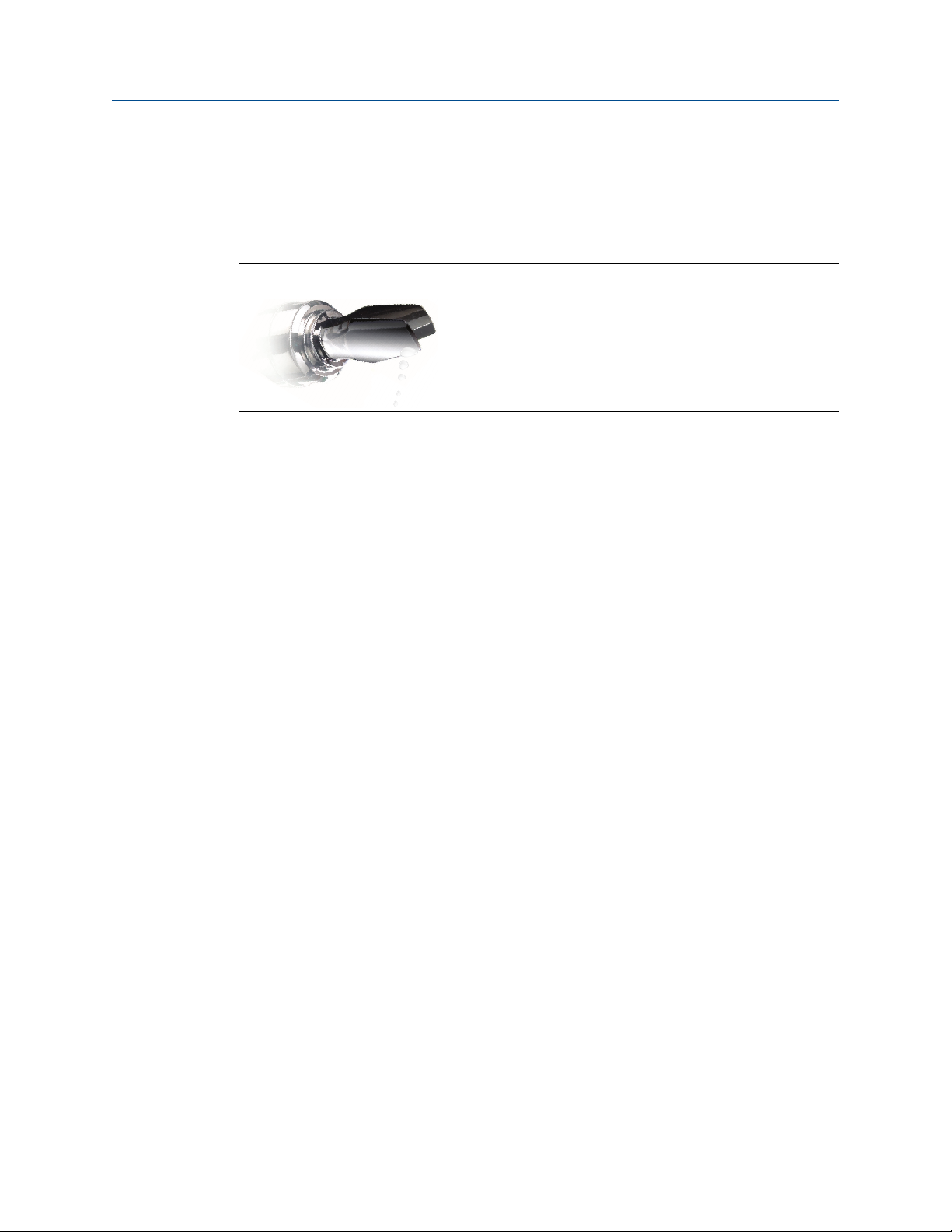
Hot surfaces
The flange and process seal may be hot at high process temperatures. Allow to cool before servicing.
3
Page 4

4
Page 5

Reference Manual Contents
00809-0100-4140 March 2022
Contents
Chapter 1 Introduction.............................................................................................................. 7
1.1 Using this manual........................................................................................................................ 7
1.2 NAMUR NE 53 revision.................................................................................................................8
1.3 Product certifications...................................................................................................................8
1.4 Product recycling/disposal...........................................................................................................8
Chapter 2 Level detector overview.............................................................................................9
2.1 Measurement principle................................................................................................................9
2.2 Process characteristics.................................................................................................................9
2.3 Vessel characteristics...................................................................................................................9
2.4 Application examples.................................................................................................................10
2.5 Components of the level detector..............................................................................................11
Chapter 3 Mechanical installation............................................................................................ 13
3.1 Safety messages........................................................................................................................ 13
3.2 Installation considerations.........................................................................................................14
3.3 Installation procedures.............................................................................................................. 22
3.4 Adjust display orientation (optional)..........................................................................................28
Chapter 4 Electrical installation................................................................................................29
4.1 Prepare the electrical connections............................................................................................. 29
4.2 Connect wiring and power up.................................................................................................... 32
Chapter 5 Configuration...........................................................................................................37
5.1 Safety messages........................................................................................................................ 37
5.2 Configuration tools....................................................................................................................38
5.3 Local Operator Interface (LOI)....................................................................................................39
5.4 Confirm correct device driver.....................................................................................................40
5.5 Confirm HART® revision capability............................................................................................. 40
Configure device using guided setup......................................................................................... 41
5.6
5.7 Verify the configuration.............................................................................................................41
5.8 Multidrop communication.........................................................................................................43
5.9 HART burst mode...................................................................................................................... 44
5.10 Security................................................................................................................................... 45
Chapter 6 Operation................................................................................................................ 49
6.1 LCD display screen messages.....................................................................................................49
6.2 Set up the LCD display............................................................................................................... 50
6.3 View measurement data............................................................................................................50
6.4 Check device status................................................................................................................... 51
6.5 Partial proof testing................................................................................................................... 53
Rosemount 2140 and 2140:SIS Level Detectors 5
Page 6

Contents Reference Manual
March 2022 00809-0100-4140
Chapter 7 Service and troubleshooting.................................................................................... 57
7.1 Safety messages........................................................................................................................ 57
7.2 Diagnostic messages................................................................................................................. 58
7.3 Troubleshooting the 4-20 mA/HART Output..............................................................................68
7.4 Service and troubleshooting tools..............................................................................................69
7.5 Opening the lid (cover).............................................................................................................. 76
7.6 Service support..........................................................................................................................76
Appendix A Specifications and reference data............................................................................. 79
A.1 General......................................................................................................................................79
A.2 Functional safety....................................................................................................................... 79
A.3 Performance specifications........................................................................................................79
A.4 Electrical specifications..............................................................................................................80
A.5 Environmental specifications.....................................................................................................81
A.6 Physical specifications............................................................................................................... 83
A.7 Dimensional drawings............................................................................................................... 84
Appendix B Configuration parameters........................................................................................ 93
B.1 Manual setup.............................................................................................................................93
B.2 Alert setup...............................................................................................................................104
Appendix C Local Operator Interface (LOI) menu trees.............................................................. 109
C.1 LOI menu trees........................................................................................................................ 109
Appendix D Signal processing................................................................................................... 111
6 Reference Manual
Page 7

Reference Manual Introduction
00809-0100-4140 March 2022
1 Introduction
1.1 Using this manual
The sections in this manual provide detailed information on installing, operating, and
maintaining the Rosemount 2140 and 2140:SIS Level Detectors.
The sections are organized as follows:
Level detector overview provides a description of the Rosemount 2140 and , and their
basic principles.
Mechanical installation contains mechanical installation instructions.
Electrical installation contains electrical installation instructions.
Configuration provides instructions on configuration of the level detector.
Operation contains operation and maintenance techniques.
Service and troubleshooting provides troubleshooting techniques for the most common
operating problems.
Specifications and reference data contains specifications and dimensional drawings.
Configuration parameters provides extended information about the configuration
parameters.
Local Operator Interface (LOI) menu trees contains complete menu maps as a reference
for when using the optional Local Operator Interface.
Signal processing contains a schematic overview of the signal processing.
Rosemount 2140 and 2140:SIS Level Detectors 7
Page 8

Introduction Reference Manual
March 2022 00809-0100-4140
1.2 NAMUR NE 53 revision
The Rosemount 2140 meets the NAMUR recommendation NE 53. Table 1-1 provides the
information necessary to ensure you have the correct device driver for your device.
Table 1-1: Identification and Compatibility According to NAMUR NE 53
Release date Device identification FDI, DD, and DTM identification Release note
NAMUR
hardware
revision
January-2017 1.0.0 1.0.0 5 1 • Initial release
March-2018 1.0.0 1.1.0 5 1 • Removed customer upgrade
(1)
NAMUR
software
revision
HART® universal
(1)
revision
(2)
7 2
7 2
Device revision
(revision level 1 and 2)
feature
• Added Media Learn and
Remote Proof Test to base
model
• Updated the Partial Proof Test
procedure
(1)
(1) NAMUR Revision is located on the device label. Differences in level 3 changes represent minor product changes as
defined per NE53. Compatibility and functionality are preserved and product can be used interchangeably.
(2) HART Revision 5 and 7 can be switched in field.
Related information
Confirm correct device driver
1.3 Product certifications
See the Rosemount 2140 Product Certifications document for detailed information on the
existing approvals and certifications.
1.4 Product recycling/disposal
Recycling of equipment and packaging should be taken into consideration and disposed of
in accordance with local and national legislation or regulations.
8 Reference Manual
Page 9

Reference Manual Level detector overview
00809-0100-4140 March 2022
2 Level detector overview
2.1 Measurement principle
The Rosemount 2140 and 2140:SIS are the world’s first wired HART® level detector using
Emerson's vibrating fork technology.
Using the principle of a tuning fork, a piezo-electric crystal oscillates the forks at their
natural frequency. Changes to the oscillation frequency are continuously monitored by
electronics as it varies depending on the liquid medium in which the forks are immersed.
The denser the liquid, the lower the oscillation frequency.
Whenever a liquid medium in a vessel (tank) or pipe drains down past the forks, it causes a
distinct frequency change. This change is detected by the electronics and a dry condition
is indicated.
Whenever a liquid medium in a vessel (tank) or pipe rises and contacts the forks, again a
distinct frequency change is detected. This time, the electronics will indicate a wet
condition.
The wet and dry conditions can be transmitted digitally as a HART signal or as a discrete
output using the analog output.
Related information
Analog output
Signal processing
2.2 Process characteristics
Emerson's vibrating fork technology is virtually unaffected by turbulence, foam, solids
content, coating products, and liquid properties. The natural frequency (1400 Hz) of the
fork avoids interference from plant vibration that may cause false detection. This allows
for minimum intrusion into the tank or pipe using a short fork.
2.2.1 Liquid-to-sediment detection
The Rosemount 2140 version of the level detector features settings to detect liquid-tosediment interface, and this works on other solids sediment types (e.g. salts). Liquids as
well as wet sediments are detected. All versions of the level detector have a Media Learn
function to fine-tune the switching point even if the media characteristics are unknown.
2.3 Vessel characteristics
The level detector should be mounted using its process connection, and in a horizontal or
vertical orientation so that the liquid medium can flow freely in the gap between the forks.
A vessel (tank) or pipe can be almost any shape or type, but check that the process
conditions are within the operating limits of the level detector.
Rosemount 2140 and 2140:SIS Level Detectors 9
Page 10

Level detector overview Reference Manual
March 2022 00809-0100-4140
Avoid installing near agitators and inlet pipes where the forks are likely to be splashed and
cause a false detection of a wet condition. False detection events can be minimized by a
programmable delay that allows time for the fork to dry.
Never force the level detector into a vessel (tank) or pipe space. Any contact with the
opposite wall, or in-tank objects, could damage the forks and other wetted-process parts.
Extended length versions require supports at regular spaced intervals.
2.4 Application examples
Applications for the Rosemount 2140 version of the level detector include overfill
prevention (Figure 2-1), high and low level alarms, pump protection, and separation
processes (Figure 2-2).
The Rosemount 2140:SIS version is certified to IEC 61508 for safety-critical applications.
Applications also include overfill prevention, high and low level alarms, and pump
protection.
Figure 2-1: Overfill Prevention
Figure 2-2: High and Low level Alarms and Pump Control
10 Reference Manual
Page 11

A
B
C
E
F
J
HH
D
A
K
G
Reference Manual Level detector overview
00809-0100-4140 March 2022
2.5 Components of the level detector
Figure 2-3 shows the components of a Rosemount 2140.
Figure 2-3: Rosemount 2140 Features
A. Terminal compartment
B. Electronics housing
C.
LOI display (optional)
D. ‘Fast drip’ forks
E. Threaded process connection (BSPT (R) or BSPP (G))
F. Tri Clamp process connection
G. Flanged process connection
H. Two cable/conduit entries (½-14 ANPT or M20 x 1.5)
I. External ground screw
J. Thermal tube (on high temperature version only)
2.5.1 Short fork technology
Using short-fork technology, the device can be used in almost all liquid applications.
Extensive research has maximized the operational effectiveness of the fork design, making
it suitable for most liquid mediums including coating liquids, aerated liquids, and slurries.
Rosemount 2140 and 2140:SIS Level Detectors 11
Page 12
Level detector overview Reference Manual
March 2022 00809-0100-4140
2.5.2 Fork design
The “fast drip” design allows the liquid to be quickly drawn away from the fork tip, making
the Rosemount 2140 quicker and more responsive in high density or viscous liquid
applications.
Figure 2-4: “Fast drip” forks
12 Reference Manual
Page 13

Reference Manual Mechanical installation
00809-0100-4140 March 2022
3 Mechanical installation
3.1 Safety messages
Instructions and procedures in this section may require special precautions to ensure the
safety of the personnel performing the operations. Information that potentially raises
safety issues is indicated by a warning symbol ( ). Refer to the following safety messages
before performing an operation preceded by this symbol.
WARNING
Failure to follow safe installation and servicing guidelines could result in death or
serious injury.
Ensure the level detector is installed by qualified personnel and in accordance with
applicable code of practice.
Use the level detector only as specified in this manual. Failure to do so may impair the
protection provided by the level detector.
The weight of a level detector with a heavy flange and extended fork length may exceed
37 lb. (18 kg). A risk assessment is required before carrying, lifting, and installing the level
detector.
For installations in hazardous locations, the level detector must be installed according to
the Rosemount 2140 and 2140:SIS Level Detectors Product Certifications document.
Repair, e.g. substitution of components, etc. may jeopardize safety and is under no
circumstances allowed.
WARNING
Explosions could result in death or serious injury.
Verify that the operating atmosphere of the level detector is consistent with the
appropriate hazardous locations certifications.
Before connecting a handheld communicator in an explosive atmosphere, ensure that the
instruments in the loop are installed in accordance with intrinsically safe or non-incendive
field wiring practices.
In explosion-proof/flameproof and non-incendive installations, do not remove the housing
covers when power is applied to the level detector.
Both housing covers must be fully engaged to meet flameproof/explosion-proof
requirements.
Rosemount 2140 and 2140:SIS Level Detectors 13
Page 14
Mechanical installation Reference Manual
March 2022 00809-0100-4140
WARNING
Electrical shock could cause death or serious injury.
Avoid contact with the leads and terminals. High voltage that may be present on leads can
cause electrical shock.
Ensure the power to the level detector is off, and the lines to any other external power
source are disconnected or not powered while wiring the level detector.
Ensure the wiring is suitable for the electrical current and the insulation is suitable for the
voltage, temperature, and environment.
WARNING
Process leaks could result in death or serious injury.
Ensure the level detector is handled carefully. If the process seal is damaged, gas might
escape from the vessel (tank) or pipe.
WARNING
Physical access
Unauthorized personnel may potentially cause significant damage to and/or
misconfiguration of end users’ equipment. This could be intentional or unintentional and
needs to be protected against.
Physical security is an important part of any security program and fundamental to
protecting your system. Restrict physical access by unauthorized personnel to protect end
users’ assets. This is true for all systems used within the facility.
CAUTION
Hot surfaces
The flange and process seal may be hot at high process temperatures. Allow to cool before
servicing.
3.2 Installation considerations
Before installing the level detector, review the safety, environmental, application, and preinstallation sections.
3.2.1 Environmental considerations
The Rosemount 2140 is weatherproof and protected against the ingress of dust, but must
be protected from flooding. Avoid installing the level detector near heat sources.
14 Reference Manual
Page 15

OKOK
Reference Manual Mechanical installation
00809-0100-4140 March 2022
Figure 3-1: Environmental Considerations
3.2.2 Application considerations
The level detectors can be mounted in an open or closed tank, or a pipe. There is a wide
range of threaded, flanged, and hygienic process connection options.
For most liquids, including coating, aerated liquids and slurries, the function is virtually
unaffected by flow, turbulence, bubbles, foam, vibration, solid particles, build-up, or
properties of the liquid medium.
Avoid process medium build-up on the forks
Avoid situations where a drying and coating process medium may create an excessive
build-up or implement preventative maintenance programs to ensure the build-up is not
enough to impair performance (see Figure 3-2).
Rosemount 2140 and 2140:SIS Level Detectors 15
Page 16

OK
Mechanical installation Reference Manual
March 2022 00809-0100-4140
Always ensure:
• There is sufficient distance between build-up on the tank wall and the fork.
• There is no risk of ‘bridging’ the level switch forks.
Examples of products that can create ‘bridging’ of forks and impair performance are
dense paper slurries and bitumen.
Figure 3-2: Avoid Product Build-up
Operating temperature and pressure ranges
Ensure the process is operating within the instrument operating temperature and pressure
ranges.
Liquid density requirements
Minimum liquid density is 0.4 SG (400 kg/m3).
Liquid viscosity range
Up to 10000 cP (centiPoise) when operating in the Normal mode.
Up to 1000 cP (centiPoise) when operating in Enhanced mode.
Foams
In almost all cases, the Rosemount 2140 is insensitive to foams (i.e. does not see the
foam).
However in rare occasions, some very dense foams may be seen as liquid; known examples
of this are found in ice-cream and orange juice manufacturing.
16 Reference Manual
Page 17

SP
HYSP
0.5
(13)
0.1
(2.5)
0.5
(13)
Reference Manual Mechanical installation
00809-0100-4140 March 2022
Switching point
The switching point varies with different liquid densities. The switching point (SP) and
hysteresis (HY) for water are shown in Figure 3-3.
Figure 3-3: Switching Point in Inches (Millimeters)
Note
When mounted vertically, a low density medium has a switching point closer to the
process connection. A high density medium has a switching point closer to fork tip.
3.2.3 Pre-installation considerations
Measurement accuracy is dependent upon the proper installation of the device. Keep in
mind the need for easy access, personnel safety, practical field calibration, and a suitable
environment for the device.
Device identification
To identify a version of the level detector, see the label on the housing.
How to handle a level detector
Handle the level detector with great care.
The weight of the level detector with a heavy flange and extended fork length may exceed
37 lb. (18 kg). A risk assessment is required to be done before carrying, lifting, and
installing the level detector.
Use both hands to carry the extended length and high temperature versions, and do not
hold a level detector by the forks (see Figure 3-4).
Rosemount 2140 and 2140:SIS Level Detectors 17
Page 18

Mechanical installation Reference Manual
March 2022 00809-0100-4140
Figure 3-4: Handling
Make no alterations to the level detector
Never make any alterations to the mechanical or electrical features of the level detector
(see Figure 3-5).
Figure 3-5: Make No Alterations
Allow adequate space outside tank or pipe
Mount a level detector so that it is removable and allow both covers to be removed.
Ensure there is also enough room for fitting cable glands and cables.
Clearances:
• A clearance of 0.75 in. (19 mm) is required for the standard covers to be removed.
• If an LCD display is installed, provide 3 in. (76.2 mm) of clearance for the extended
cover to be removed.
Note
The electronics housing can be rotated for optimal viewing position of an LCD display (if
fitted) and to assist with the cabling.
18 Reference Manual
Page 19

D
A
B
Reference Manual Mechanical installation
00809-0100-4140 March 2022
Covers installation
Ensure a proper seal by installing the electronics housing covers so that metal contacts
metal. Always use Emerson's O-rings.
Mounting orientation
Mount the Rosemount 2140 at any angle that allows the level of the process medium to
rise, fall, or flow through the fork gap.
Related information
Correct fork alignment
Pipe installation requirements
• The inside pipe diameter (D) must be 1.4 in. (35 mm) or larger.
• Ensure the fork tines intrude at least 0.9 in. (22 mm) into the pipe.
• Keep at least 0.3 in. (7 mm) of clearance between the fork tines and the pipe wall.
Figure 3-6: Pipe Installation
A. Minimum intrusion 0.9 in. (22 mm)
B. Minimum clearance 0.3 in. (7 mm)
Rosemount 2140 and 2140:SIS Level Detectors 19
Page 20

B
B
A
Mechanical installation Reference Manual
March 2022 00809-0100-4140
Other recommendations
• Avoid:
— Installing near to liquid entering the tank at the filling-point.
— Heavy splashing on the forks.
Increasing the sensor output delay reduces accidental detection caused by splashing.
• Always ensure:
— The overall system is tested during commissioning.
— The installation does not create tank crevices around the forks where a liquid
medium may collect. This event can happen with high-viscosity and high-density
liquids.
— The forks do not come into contact with the vessel (tank) or pipe wall, internal
fittings, or any other obstructions.
• Extra consideration is needed if the plant vibration is close to the 1400 Hz operating
frequency of the fork.
Required supports for extended fork
Supporting the extended fork avoids long fork length vibration.
Figure 3-7: Vertical Installation
20 Reference Manual
B. 3.28 ft. (1.0 m)
A. Maximum 3.28 ft. (1.0 m)
Page 21

A
B B
Reference Manual Mechanical installation
00809-0100-4140 March 2022
Figure 3-8: Horizontal Installation
A. Maximum 3.28 ft. (1.0 m)
3.28 ft. (1.0 m)
B.
Rosemount 2140 and 2140:SIS Level Detectors 21
Page 22

B
A
C
D
E
F
Mechanical installation Reference Manual
March 2022 00809-0100-4140
3.3 Installation procedures
3.3.1 Process connection seals
Figure 3-9: Process Connection Seals
A. PTFE tape
B. NPT or BSPT (R) thread
C. Gasket
D. BSPP (G) thread
22 Reference Manual
E. Tri Clamp
F. The Tri Clamp seal is supplied in an accessory kit
Page 23

OKOK
OK
C
A
B
OK
A
B
OK
A
B
Reference Manual Mechanical installation
00809-0100-4140 March 2022
3.3.2 Correct fork alignment
Fork alignment in a vessel (tank) installation
The fork is correctly aligned by positioning the groove or notch as indicated (Figure 3-10).
Figure 3-10: Correct Fork Alignment for Vessel (Tank) Installation
A. Tri Clamp process connections have a circular notch
B. Threaded process connections have a groove
C.
Flanged process connections have a circular notch
Fork alignment in a pipe installation
The fork is correctly aligned by positioning the groove or notch as indicated (Figure 3-11).
Figure 3-11: Correct Fork Alignment for Pipe Installation
A. Tri Clamp process connections have a circular notch
B. Threaded process connections have a groove
Rosemount 2140 and 2140:SIS Level Detectors 23
Page 24

A
A
Mechanical installation Reference Manual
March 2022 00809-0100-4140
3.3.3 Mounting the threaded version
Threaded vessel (tank) or pipework connection
Procedure
1. Seal and protect the threads. Use anti-seize paste or PTFE tape according to site
procedures.
A gasket may be used as a sealant for BSPP (G) threaded connections.
2. Screw the level detector into the process connection.
Note
Tighten using the hexagon nut only.
Figure 3-12: Vertical Installation
A. Gasket for BSPP (G) threaded connection
Figure 3-13: Horizontal Installation
A. Gasket for BSPP (G) threaded connection
24 Reference Manual
Page 25

A
Reference Manual Mechanical installation
00809-0100-4140 March 2022
Threaded flange connection
Procedure
1. Place the customer-supplied flange and gasket on the vessel (tank) nozzle.
A. Gasket (customer supplied)
2. Tighten the bolts and nuts with sufficient torque for the flange and gasket.
3. Seal and protect the threads. Use anti-seize paste or PTFE tape according to site
procedures.
A gasket may be used as a sealant for BSPP (G) threaded connections.
Rosemount 2140 and 2140:SIS Level Detectors 25
Page 26

A
A
Mechanical installation Reference Manual
March 2022 00809-0100-4140
4. Screw the level detector into the flange thread.
Note
Tighten using the hexagon nut only.
A. Gasket for BSPP (G) threaded connection
3.3.4 Mounting the flanged version
Procedure
1. Lower the level detector into the nozzle.
A. Gasket (customer supplied)
26 Reference Manual
Page 27

A
Reference Manual Mechanical installation
00809-0100-4140 March 2022
2. Tighten the bolts and nuts with sufficient torque for the flange and gasket.
3.3.5 Mounting the Tri Clamp version
Procedure
1. Lower the level detector into the flange face.
A. Seal (supplied with Tri Clamp)
Rosemount 2140 and 2140:SIS Level Detectors 27
Page 28
H3/32 in.
Torque 30 in-lb (3 Nm)
Mechanical installation Reference Manual
March 2022 00809-0100-4140
2. Fit the Tri Clamp.
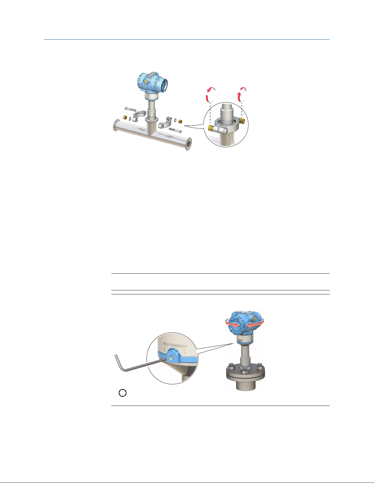
3.4 Adjust display orientation (optional)
To improve field access to wiring or to better view the optional LCD display:
Procedure
1. Loosen the set screw until the level detector housing can rotate smoothly.
Do not unscrew all the way. Rotating the housing, without this screw in place, can
damage the internal wiring.
2.
First, rotate the housing clockwise to the desired location.
If the desired location cannot be achieved due to thread limit, rotate the housing
counterclockwise.
3. Re-tighten the set screw.
Note
Do not attempt to rotate the display beyond the thread limits.
Figure 3-14: Housing Rotation
28 Reference Manual
Page 29

Reference Manual Electrical installation
00809-0100-4140 March 2022
4 Electrical installation
4.1 Prepare the electrical connections
4.1.1 Cable selection
Use 24–14 AWG wiring. Twisted-pairs and shielded wiring is recommended for
environments with high EMI (electromagnetic interference). Two wires can be safely
connected to each terminal screw.
4.1.2 Cable glands/conduits
For intrinsically safe, explosion-proof/flameproof, and dust-proof installations, only use
certified cable glands or conduit entry devices. Ordinary location installations can use
suitably rated cable glands or conduit entry devices to maintain the Ingress Protection (IP)
rating.
Unused conduit entries must always be sealed with a suitably rated blanking/stopping
plug.
Note
Do not run signal wiring in conduit or open trays with power wiring or near heavy electrical
equipment.
4.1.3 Power supply
Each level detector operates on 10.5 – 42.4 Vdc (10.5 – 30 Vdc in Intrinsically Safe
installations) at the level detector terminals.
4.1.4 Power consumption
Maximum of 1 W, and current maximum is 23 mA.
4.1.5 Hazardous areas
When the device is installed in hazardous areas (classified locations), local regulations and
the conditions-of-use specified in applicable certificates must be observed. Review the
Rosemount 2140 Product Certifications document for information.
4.1.6 Load limitations
For HART® communications, a minimum load resistance of 250 Ω is required.
The maximum loop resistance is determined by the voltage level of the external power
supply (see Figure 4-1).
Rosemount 2140 and 2140:SIS Level Detectors 29
Page 30

1400
1200
1000
800
600
400
200
0
100 20 30 40 50
250
587
848
1392
16.3 24 42.4
10.5
A
B
-
+
-
+
Fn
1
2
3
4
5
6
7
8
9
0
-
.
A
C
D
E
FB
Electrical installation Reference Manual
March 2022 00809-0100-4140
Figure 4-1: Load Limitations
Maximum loop resistance = 43.5 × (external power supply voltage - 10.5)
A. Loop resistance in Ohms (Ω)
B.
External power supply voltage (Vdc)
4.1.7 Wiring diagram
Figure 4-2: 4-20 mA/HART® Communication
A. Handheld communicator
B. Approved IS barrier (for Intrinsically Safe installations only)
HART modem
C.
D. Load resistance (≥250 Ω)
E. Current meter
F. Power supply
30 Reference Manual
Page 31

A
B
A
B
B
C C
D
Reference Manual Electrical installation
00809-0100-4140 March 2022
4.1.8 Grounding
Make sure grounding is done according to national and local electrical codes. Failure to do
so may impair the protection provided by the equipment.
Grounding the housing
The most effective grounding method is direct connection to earth ground with minimal
impedance. There are two grounding screw connections provided (see Figure 4-3).
Figure 4-3: Ground Screws
A. External ground screw
Internal ground screw
B.
Signal cable shield grounding
Make sure the instrument cable shield is:
• Trimmed close and insulated from touching the housing.
• Continuously connected throughout the segment.
• Connected to a good earth ground at the power supply end.
Figure 4-4: Signal Cable Shield Grounding at Power Supply End
A. Trim shield and insulate
B. Minimize distance
Trim shield
C.
D. Connect shield back to the power supply ground
Transient protection terminal block grounding
The level detector can withstand electrical transients of the energy level usually
encountered in static discharges or induced switching transients. However, high-energy
transients, such as those induced in wiring from nearby lightning strikes, can damage the
level detector.
Rosemount 2140 and 2140:SIS Level Detectors 31
Page 32

M2.5
Electrical installation Reference Manual
March 2022 00809-0100-4140
A transient protection terminal block can be ordered as an installed option (code T1). The
lightning bolt symbol in identifies the transient protection terminal block.
Note
The transient protection terminal block does not provide transient protection unless the
housing is properly grounded.
4.2 Connect wiring and power up
Procedure
1. Verify the power supply is disconnected.
2. Remove the field terminals cover.
In an explosion-proof/flameproof installation, do not remove the level detector
covers when power is applied to the unit. Covers are also not to be removed in
extreme environmental conditions.
a)
Turn the jam screw clockwise until it is completely threaded into the housing.
b) Turn the cover counter-clockwise until it is removed from the housing.
Keep the cover O-ring safe. Replace the O-ring if it is worn or damaged.
32 Reference Manual
Page 33

M20
½-14 NPT
M20 x 1.5
Reference Manual Electrical installation
00809-0100-4140 March 2022
3. Remove the plastic plugs.
4. Pull the cable through the cable gland/conduit.
Identification of thread size and type:
5. Connect the cable wires.
Torque 7 in-lb (0.8 Nm)
6. Ensure proper grounding.
Rosemount 2140 and 2140:SIS Level Detectors 33
Page 34

Electrical installation Reference Manual
March 2022 00809-0100-4140
7. Tighten the cable gland.
Apply PTFE tape or other sealant to the threads.
Note
Make sure to arrange the wiring with a drip loop.
8. Plug and seal the unused conduit connection to avoid moisture and dust
accumulation inside the housing.
Apply PTFE tape or other sealant to the threads.
34 Reference Manual
Page 35

M2.5
M2.5
Reference Manual Electrical installation
00809-0100-4140 March 2022
9. Attach and tighten the cover.
a) Verify the cover jam screw is completely threaded into the housing.
b) Attach and tighten the cover.
Make sure the cover is fully engaged. There should be no gap between the
cover and the housing.
10. Required for explosion-proof/flameproof installations only:
a) Turn the cover jam screw counterclockwise until it contacts the cover.
b) Turn the jam screw an extra ½ turn counterclockwise to secure the cover.
c) Verify that the cover cannot be removed.
11.
Connect the power supply.
Rosemount 2140 and 2140:SIS Level Detectors 35
Page 36

Electrical installation Reference Manual
March 2022 00809-0100-4140
36 Reference Manual
Page 37

Reference Manual Configuration
00809-0100-4140 March 2022
5 Configuration
5.1 Safety messages
Instructions and procedures in this section may require special precautions to ensure the
safety of the personnel performing the operations. Information that potentially raises
safety issues is indicated by a warning symbol ( ). Refer to the following safety messages
before performing an operation preceded by this symbol.
WARNING
Failure to follow safe installation and servicing guidelines could result in death or
serious injury.
Ensure the level detector is installed by qualified personnel and in accordance with
applicable code of practice.
Use the level detector only as specified in this manual. Failure to do so may impair the
protection provided by the level detector.
The weight of a level detector with a heavy flange and extended fork length may exceed
37 lb. (18 kg). A risk assessment is required before carrying, lifting, and installing the level
detector.
For installations in hazardous locations, the level detector must be installed according to
the Rosemount 2140 and 2140:SIS Level Detectors Product Certifications document.
Repair, e.g. substitution of components, etc. may jeopardize safety and is under no
circumstances allowed.
WARNING
Explosions could result in death or serious injury.
Verify that the operating atmosphere of the level detector is consistent with the
appropriate hazardous locations certifications.
Before connecting a handheld communicator in an explosive atmosphere, ensure that the
instruments in the loop are installed in accordance with intrinsically safe or non-incendive
field wiring practices.
In explosion-proof/flameproof and non-incendive installations, do not remove the housing
covers when power is applied to the level detector.
Both housing covers must be fully engaged to meet flameproof/explosion-proof
requirements.
Rosemount 2140 and 2140:SIS Level Detectors 37
Page 38

Configuration Reference Manual
March 2022 00809-0100-4140
WARNING
Electrical shock could cause death or serious injury.
Avoid contact with the leads and terminals. High voltage that may be present on leads can
cause electrical shock.
Ensure the power to the level detector is off, and the lines to any other external power
source are disconnected or not powered while wiring the level detector.
Ensure the wiring is suitable for the electrical current and the insulation is suitable for the
voltage, temperature, and environment.
WARNING
Process leaks could result in death or serious injury.
Ensure the level detector is handled carefully. If the process seal is damaged, gas might
escape from the vessel (tank) or pipe.
WARNING
Physical access
Unauthorized personnel may potentially cause significant damage to and/or
misconfiguration of end users’ equipment. This could be intentional or unintentional and
needs to be protected against.
Physical security is an important part of any security program and fundamental to
protecting your system. Restrict physical access by unauthorized personnel to protect end
users’ assets. This is true for all systems used within the facility.
CAUTION
Hot surfaces
The flange and process seal may be hot at high process temperatures. Allow to cool before
servicing.
5.2 Configuration tools
• Field Device Integration (FDI) based systems
• Device Descriptor (DD) based systems
• Device Type Manager (DTM™ ) based systems
• Local Operator Interface (LOI)
38 Reference Manual
Page 39

A
B
Reference Manual Configuration
00809-0100-4140 March 2022
5.3 Local Operator Interface (LOI)
The LOI requires option code M4 to be selected when ordering a level detector.
It uses a character display (Figure 5-1) to indicate the live output state, diagnostic
messages, and menus. There are two rows of characters, with 8 on the upper row and 6 on
the lower row.
Figure 5-1: Local Operator Interface (LOI) Display
Related information
Local Operator Interface (LOI) menu trees
5.3.1 LOI configuration buttons
To activate the LOI, push any of the configuration buttons. Left and right configuration
buttons are located on the LCD display (accessible after removing a housing cover) and
duplicated underneath the moveable top-tag.
Figure 5-2: LOI Configuration Buttons
A. Internal configuration buttons, left and right
B. External configuration buttons, left and right
5.3.2 LOI button operation
Table 5-1 shows examples of the basic configuration button functionality. Some features
in the LOI menu use multiple screens to complete their configuration. Any data entered is
saved on a screen-by-screen basis, and the LOI indicates this by flashing “SAVED” on the
LCD display each time.
Rosemount 2140 and 2140:SIS Level Detectors 39
Page 40

Configuration Reference Manual
March 2022 00809-0100-4140
Table 5-1: LOI Button Operation
LOI screen Button Function
Left NO
Right YES
Left SCROLL DOWN
Right ENTER
5.4 Confirm correct device driver
Procedure
1. Verify that the correct FDI/DD/DTM Package is loaded on your systems to ensure
proper communication.
2.
Download the latest FDI/DD/DTM Package at Emerson.com/DeviceInstallKits or
FieldCommGroup.org.
Related information
NAMUR NE 53 revision
5.5 Confirm HART® revision capability
If using HART-based control or asset management systems, confirm the HART capability
of those systems prior to installation of the device. Not all systems are capable of
communicating with HART Revision 7 protocol. This device can be configured for either
HART Revision 5 or 7.
5.5.1 Switch HART revision
Procedure
1. Select
2. Under Communication Settings, select Change HART Revision and follow the on-
5.5.2 Switch HART revision with a generic menu
If the HART configuration tool is not capable of communicating with a HART Revision 7
device, it will load a generic menu with limited capability.
Configure → Manual Setup → HART.
screen instructions.
Procedure
Locate the “Message” field.
• To switch to HART Revision 5, enter HART5 and 27 spaces in the message field.
40 Reference Manual
Page 41

Reference Manual Configuration
00809-0100-4140 March 2022
• To switch to HART Revision 7, enter HART7 and 27 spaces in the message field.
5.5.3 Switch HART revision using the LOI
To switch the HART revision mode using the LOI (Local Operator Interface):
Procedure
1. Press any LOI configuration button to activate the menu.
Scroll down (
2.
3. Scroll down ( ) and then select HART REV ( ) .
4. To change HART revision, select
HART REV 7 ( ).
5. Exit the menu system by either waiting one minute for the
scrolling down menus to find and select BACK TO MENU and EXIT MENU.
) and then select EXTENDED MENU ( ) .
HART REV 5 (
), or scroll down ( ) and then select
EXIT MENU? prompt, or
5.6 Configure device using guided setup
The options available in the Guided Setup wizard include all items required for basic
operation.
Procedure
Select
1.
2. Select Basic Setup and follow the on-screen instructions.
Configure → Guided Setup.
5.6.1 Configure using the LOI
The Guided Setup wizard is not available on the LOI (Local Operator Interface). See the
appendix Configuration parameters for the LOI instructions to configure basic parameters,
and then return here to verify configuration.
5.7 Verify the configuration
It is recommended that configuration parameters are verified prior to using the level
detector live in a process.
5.7.1 Verify configuration using a handheld communicator
Table 5-2 lists the configuration parameters to be reviewed before using the level detector
live in a process. From the HOME screen of the handheld communicator, enter the fast key
sequences as listed.
Rosemount 2140 and 2140:SIS Level Detectors 41
Page 42

Configuration Reference Manual
March 2022 00809-0100-4140
Table 5-2: Verifying Configuration (Fast Key Sequences)
Parameter Fast key sequence
HART 7 HART 5
Tag 1, 8, 1, 2 1, 8, 1, 1
Model 1, 8, 1, 3 1, 8, 1, 3
Primary Variable 3, 2, 1, 1 3, 2, 1, 1
Sensor Operating Mode 2, 2, 1, 1, 1 2, 2, 1, 1, 1
Sensor Output Delay 2, 2, 1, 1, 2 2, 2, 1, 1, 2
Media Density 2, 2, 1, 1, 3 2, 2, 1, 1, 3
Sensor Fault Delay 2, 2, 1, 3, 2 2, 2, 1, 3, 2
(4)
(4)
(2)
(2)
(1)
(3)(4)
(3)(4)
(3)
(3)
2, 2, 2, 1, 1 2, 2, 2, 1, 1
2, 2, 2, 1, 3 2, 2, 2, 1, 3
2, 2, 2, 1, 4 2, 2, 2, 1, 4
2, 2, 2, 2, 2 2, 2, 2, 2, 2
2, 2, 2, 2, 3 2, 2, 2, 2, 3
2, 2, 2, 5, 3 2, 2, 2, 5, 3
2, 2, 2, 5, 6 2, 2, 2, 5, 6
2, 2, 2, 5, 4 2, 2, 2, 5, 4
2, 2, 2, 5, 5 2, 2, 2, 5, 5
Current Output Type
Custom Off Current
Custom On Current
PV URV (Upper Range Value)
PV LRV (Lower Range Value)
High Alarm Level
Low Alarm Level
High Saturation Level
Low Saturation Level
Alarm Switch Position/Direction 2, 2, 2, 5, 2 2, 2, 2, 5, 2
(1) Only applicable when the Primary Variable is mapped to the Output State variable.
(2) Only applicable when Current Output Type is set to “Custom”.
(3) Only applicable when the Primary Variable is mapped to the Sensor Frequency or Scaled Variable
variables.
(4) Alarm level and saturation level depend on the Alarm Level switch setting and the ordered Alarm
Level option code.
5.7.2 Verify configuration using the LOI
Table 5-3 lists the configuration parameters to be reviewed on the LOI (Local Operator
Interface) before using the level detector live in a process.
Procedure
1. Press any LOI configuration button to activate the menu.
2.
Select VIEW CONFIG (
3. Scroll down ( ) to review the parameters.
4. Exit the menu system by either waiting one minute for the
scrolling down menus to find and select BACK TO MENU and EXIT MENU.
).
EXIT MENU? prompt, or
42 Reference Manual
Page 43

Reference Manual Configuration
00809-0100-4140 March 2022
Table 5-3: Verifying Configuration (LOI)
Parameter Information
TAG Free-form text for giving the device an identity
MODEL e.g. “2140”
T Range Operating temperature range
IS PV Primary Variable mapping
S UNIT Secondary Variable units
T UNIT Electronics temperature units
OP MODE Operating mode
DENSITY Media density
O DLY Sensor output delay
F DLY Fault output delay
(1)
(1)
(1)
Analog Output operating mode
Custom mA output for ‘off’ output state
Custom mA output for ‘on’ output state
AOMODE
OFF MA
ON MA
S-START Device test/proof test at start
(2)
URV
LRV
(2)
Upper range value for analog output
Lower range value for analog output
DAMPING Scaled Variable damping
HIALRM
LOALRM
HI SAT
LO SAT
(3)
(3)
(2)(3)
(2)(3)
High alarm level
Low alarm level
High saturation level
Low saturation level
ALARM Alarm switch position/direction
SECURE Security switch position
(1) Only visible when the Primary Variable (“PV”) is mapped to the Output State variable.
(2) Only visible when the Primary Variable (“PV”) is mapped to the Sensor Frequency or
Scaled Variable variables.
(3) Alarm level and saturation level depend on the Alarm Level switch setting and the
ordered Alarm Level option code.
5.8 Multidrop communication
Multidropping refers to the connection of several devices to a single communications
transmission line. Communication between the host device and another device takes
place digitally with the analog output of the level detector deactivated. Figure 5-3 shows a
typical multidrop network.
Rosemount 2140 and 2140:SIS Level Detectors 43
Page 44

A
B
Configuration Reference Manual
March 2022 00809-0100-4140
Figure 5-3: Typical Multidrop Network
A. HART modem
B. Power supply
Multidrop installation requires consideration of the update rate necessary from each
device, the combination of different device types, and the length of the transmission line.
Communication with devices can be accomplished with HART modems and a host
implementing the HART protocol. Each device is identified by a unique address and
responds to the commands defined in the HART protocol.
Note
A multidrop device in HART Revision 7 mode has a fixed analog output of 4 mA for all but
one device. Only one device is allowed to have an active analog signal.
The level detector is set to address zero (0) at the factory, which allows operation in the
standard point-to-point manner with a 4–20 mA output signal.
5.8.1 Establish multidrop communication
To activate multidrop communication, the address must be changed to a number from 1
to 15 for HART Revision 5, or 1 to 63 for HART Revision 7. This change deactivates the 4–
20 mA analog output, sending it to 4mA.
It also disables the failure mode alarm signal, which is controlled by the upscale/downscale
switch position. Failure signals in multidropped devices are communicated through HART
messages.
Procedure
1. Select
2. Under Communication Settings, select Change Polling Address and follow the on-
Configure → Manual Setup → HART.
screen instructions.
5.9 HART burst mode
Burst mode is compatible with the analog output signal. Due to the way that HART
44 Reference Manual
protocol features simultaneous digital and analog data transmission, the analog value can
drive other equipment in the loop while the control system is receiving the digital
information.
Page 45

Reference Manual Configuration
00809-0100-4140 March 2022
Burst mode applies only to the transmission of dynamic variables (PV, SV, TV, and QV), and
does not affect the way other data is accessed. However, when activated, burst mode can
slow down communication of non-dynamic variable data to the host by 50%.
Access to information, other than dynamic variables, is obtained through the normal polland-response method of HART communication. The configuration tool or control system
may request any of the information that is normally available while the device is in burst
mode. Between each message sent by the device, a short pause allows a host
(configuration tool or control system) to initiate a request.
5.9.1 Configure burst mode
Prerequisites
Check if the host system supports burst mode and what options are required. The burst
from the level detector will be at a continuous rate of once every 0.5 seconds.
Procedure
1. Select
2. Under Burst Mode Configuration, in the Burst mode list, select Enabled.
3. In the Burst command list, select the desired burst option (e.g. PV, SV, TV, and
4. Optional: Select Configure Additional Messages to configure Burst Message 2 and
Configure → Manual Setup → HART.
QV).
Burst Message 3.
5.10 Security
There are four security methods:
• Security switch
• HART lock
• Configuration button lock
• Local Operator Interface (LOI) password
5.10.1 Alarm and security switches
Alarm level switch
Under alarm conditions, the output current is forced to a high or low level beyond the
normal 4 mA to 20 mA operating range.
The Alarm Level hardware switch is set to a 'H' or 'L' position to determine if it is the high or
low alarm current. Figure 5-4 shows the Alarm Level switch inside the housing.
Security switch
The security switch is set to the Locked position to prevent configuration changes using
the optional Local Operator Interface (LOI) or HART® interfaces.
Figure 5-4 shows the security switch inside the housing.
Rosemount 2140 and 2140:SIS Level Detectors 45
Page 46

Without LOI display
With LOI display
A
B
Configuration Reference Manual
March 2022 00809-0100-4140
Figure 5-4: Alarm Level and Security Switches
A. Alarm level switch
Security switch
B.
5.10.2 Set the position of the security switch
When the security switch is set to the locked position ( ) , all configuration requests made
using HART, LOI, or local configuration buttons are rejected.
Procedure
1. Set process loop to manual and remove power.
2. Remove the housing cover.
Use a small screwdriver to slide the security switch to the preferred position.
3.
4. Replace the housing cover.
Note
The cover must be fully engaged with the cover jam screw to comply with
explosion-proof requirements.
View the security switch status
The position of the security switch can be checked without removing the housing cover.
Procedure
Select Service Tools → Maintenance → Security.
The Write protect box shows the status of the security switch.
View the security switch status using the LOI
46 Reference Manual
The position of the security switch can be checked without removing the housing cover.
Procedure
Press any LOI configuration button to activate the menu.
The display shows LOCK WRITE if the security switch is enabled.
Page 47

Reference Manual Configuration
00809-0100-4140 March 2022
5.10.3 Set the HART lock
The HART Lock function prevents HART commands from making changes to the
configuration.
Prerequisites
The device must be using HART Revision 7.
Procedure
1. Select
2. Under HART Lock (Software), select Lock/Unlock and follow the on-screen
Related information
Switch HART revision
Configure → Manual Setup → Security.
instructions.
5.10.4 Set the configuration button lock
The configuration button lock disables all local button functionality.
Procedure
Select
1.
2. In the Configuration Buttons list, select Disabled to lock the external local buttons
Configure → Manual Setup → Security.
or Enabled to unlock.
5.10.5 Local Operator Interface (LOI) lock
A Local Operator Interface (LOI) password can used to prevent the review and modification
of the level detector configuration using the LOI. The password is a 4-digit code that is to
be set by the user.
Note
This password protection does not prevent access to the level detector configuration
using HART communications.
Set the LOI password
Procedure
1. Select
2. Select Configure Password (LOI Password Protection in handheld communicator)
Configure → Manual Setup → Security.
and follow the on-screen instructions.
Set the LOI password using the LOI
Procedure
1. Press any LOI configuration button to activate the menu.
2. Scroll down (
Rosemount 2140 and 2140:SIS Level Detectors 47
) and then select EXTENDED MENU ( )
Page 48

Configuration Reference Manual
March 2022 00809-0100-4140
3. Scroll down ( ) and then select PASSWORD ( ) .
4. Enable the LOI password protection.
5.
Enter a 4-digit number as the password.
6. Exit the menu system by either waiting one minute for the EXIT MENU? prompt, or
scrolling down menus to find and select BACK TO MENU and EXIT MENU.
48 Reference Manual
Page 49

Reference Manual Operation
00809-0100-4140 March 2022
6 Operation
6.1 LCD display screen messages
The optional Local Operator Interface (LOI) includes a LCD display that shows output
variables and abbreviated diagnostic messages.
Figure 6-1: LOI and LCD Display (Option Code M4)
Variable screens
The level detector can display the following variables:
Table 6-1: LCD Display Variables
Parameter Presentation on
display
Output State
Sensor State STATE Live fork state: ‘dry’ (0.0) or ‘wet’ (1.0).
Sensor Frequency Hz Live vibration frequency of the fork.
Percent of Range
Primary Variable
Scaled Variable
Electronics
Temperature
Supply Voltage V The live voltage at the terminals.
Analog Output MA The live analog output current.
(1) Default parameter displayed.
(2) Not available for Rosemount 2140:SIS.
(1)
(2)
OUTPUT Live output state: ‘off’ (0.0) or ‘on’ (1.0).
%RANGE A live variable value expressed in percent within
SCALED A live variable calculated from a scaling table (as
DEG F / DEG C The live temperature at the electronics.
Description
a range defined by a Lower Range Value (LRV)
and an Upper Range Value (URV).
defined by pairs of input/scaled values).
Rosemount 2140 and 2140:SIS Level Detectors 49
Page 50

Operation Reference Manual
March 2022 00809-0100-4140
6.2 Set up the LCD display
It is possible to specify the variables to be presented on the optional LCD display.
Procedure
1. Select
2. Select the desired variables to be displayed on the LCD display.
Configure → Manual Setup → Display.
6.2.1 Set up the LCD display using the LOI
It is possible to specify the variables to be presented on the optional LCD display.
Procedure
1. Press any LOI configuration button to activate the menu.
Scroll down (
2.
3. OUTPUT is the first variable in this menu.
Select
a)
b) Select
4. For all other variables of interest:
a) Scroll down (
b) Select
The last item, STARTUP, enables or disables the startup screens when the
level detector is started. By default, this is not enabled. Startup screens
include a display test and the VIEW CONFIG content.
) and then select DISPLAY ( )
OUTPUT (
No or Yes to answer the prompt asking if it is to be displayed or not.
No or Yes to answer the prompt asking if it is to be displayed or not.
).
) and then select ( ) .
5. Exit the menu system by either waiting one minute for the EXIT MENU? prompt, or
scrolling down menus to find and select BACK TO MENU and EXIT MENU.
6.3 View measurement data
Current measurement data of the primary variables are presented on the Overview screen.
To view all current measurement values:
Procedure
Service Tools → Variables.
Select
1.
2. Select Variable Summary, Mapped Variables, or Device Variables.
6.3.1 Interpret measurement status
A “Good” or “Bad” status next to a value is an indication of the reliability or integrity of the
data being received, not an indication of whether or not the value is within the configured
upper or lower ranges. A value that triggers an alert, such as a high or low temperature
indication, will change the overall status of the device, but the measurement might still be
indicated as “Good” if the reliability of the data is good.
50 Reference Manual
Page 51

Reference Manual Operation
00809-0100-4140 March 2022
6.3.2 View measurement data using the LOI
The optional LOI and LCD is configurable to show a different variable every few seconds.
Related information
Set up the LCD display using the LOI
6.4 Check device status
The overall device status is presented under the Overview screen. The device reports
diagnostic alerts when there is a device malfunction.
Procedure
1. Go to the
2. If status is anything other than Good, select the button in the device status image to
open a window with Active Alerts.
Active Alerts can also be obtained via Service Tools → Alerts.
Related information
Diagnostic messages
Overview screen to view the overall device status.
Rosemount 2140 and 2140:SIS Level Detectors 51
Page 52

Operation Reference Manual
March 2022 00809-0100-4140
6.4.1 Device status images
Table 6-2: Presentation of Device Status Images as per NAMUR NE 107 – AMS Device Manager
Device status image Category Description Action
Good No active alert. N/A
Failure At least one Failure alert is
active.
Function Check At least one Function Check alert
is active (and no Failure alerts).
Out of
Specification
Maintenance
Required
At least one Out of Specification
alert is active (and no Failure or
Function Check alerts).
At least one Maintenance
Required alert is active (and no
Failure, Function Check, or Out
of Specification alerts).
Click the Troubleshoot button
to open a window with active
alerts together with
recommended actions.
Click the Investigate button to
open a window with active alerts
together with recommended
actions.
52 Reference Manual
Page 53

Reference Manual Operation
00809-0100-4140 March 2022
6.5 Partial proof testing
Partial proof testing simulates sensor changes from dry-to-wet and wet-to-dry when a
level detector is already installed, but does not require the actual process to change.
Comprehensive proof testing requires the forks to be immersible in a liquid and observing
the output changes.
The level detector has partial proof testing support as standard, and it can be triggered
locally using the Local Operator Interface (if fitted) or remotely using a HART command
e.g. from a DD-based host system.
Initially, the device diagnostics are checked by the level detector before simulating sensor
states. Any detected faults will end the proof test immediately, requiring further
investigation.
Proof testing then exercises the analog output to produce the electrical currents
representing:
• The ‘off’ and ‘on’ states (if configured for a switched output).
• Lower and upper range values (if configured for a 4–20 mA output).
• High and low alarms.
When the Primary Variable is mapped to the Scaled Variable
variables, the analogue output is also exercised from the low saturation level to the high
saturation level.
For Safety Instrumented System (SIS) applications, the Rosemount 2140:SIS must be
tested at regular intervals. This is to detect any failures not automatically detected by the
device self-test at start-up and the continuous fork sensor diagnostics when operating in
Enhanced mode.
Related information
Rosemount 2140:SIS Safety Manual
6.5.1 Start the remote partial proof test
Procedure
1. Select
2. Select Partial Proof-Test and follow the on-screen instructions.
Service Tools → Maintenance → Test.
(1)
or Sensor Frequency device
(1) Available on Rosemount 2140 version of the level detector only.
Rosemount 2140 and 2140:SIS Level Detectors 53
Page 54

Operation Reference Manual
March 2022 00809-0100-4140
6.5.2 Start the local partial proof test
By default, the partial proof testing sequence is not started at every power-up. It can be
started by an operator using the Local Operator Interface (LOI).
Procedure
In the menu system, select TEST → PROOF TEST or, when no LOI is not fitted, by using the
single external push-button fitted to the top of the level detector (underneath the
movable nameplate).
6.5.3 Configure the proof test function
Procedure
1. Select
2. Set the Duration as desired.
3. In the Start-up Proof-Test list, select Enabled or Disabled.
Configure → Manual Setup → Operation → Proof Test.
Configure proof test function using the LOI
Procedure
1. Press any LOI configuration button to activate the menu.
2. Scroll down (
3. Scroll down ( ) and then select PROOF TEST ( ).
4. Choose the proof-test parameter to change:
Select DURATION for setting how long the partial proof-test lasts.
a)
b) Select START-UP for setting if partial proof-testing at start-up is enabled or
disabled
5. Exit the menu system by either waiting one minute for the EXIT MENU? prompt, or
scrolling down menus to find and select BACK TO MENU and EXIT MENU.
) and then select EXTENDED MENU ( ).
Duration of the proof test routine
The Proof-Test Duration parameter determines the duration of the whole partial prooftesting sequence.
Four steps performed are:
• Low Alarm Current step
— The analog output current is overridden to the Low Alarm level (as configured).
• Off Current step
— The analog output current is overridden to the level of the ‘off’ switched output
state (as configured).
• On Current step
— The analog output current is overridden to the level of the ‘on’ switched output
state (as configured).
54 Reference Manual
Page 55

Reference Manual Operation
00809-0100-4140 March 2022
• High Alarm Current step
— The analog output current is overridden to the High Alarm level (as configured).
Note
Setting a value of “0 s” (zero seconds) results in the analog output not being exercised
during the proof-test. Only a diagnostic check of the device is performed in this case.
Rosemount 2140 and 2140:SIS Level Detectors 55
Page 56

Operation Reference Manual
March 2022 00809-0100-4140
56 Reference Manual
Page 57

Reference Manual Service and troubleshooting
00809-0100-4140 March 2022
7 Service and troubleshooting
7.1 Safety messages
Instructions and procedures in this section may require special precautions to ensure the
safety of the personnel performing the operations. Information that potentially raises
safety issues is indicated by a warning symbol ( ). Refer to the following safety messages
before performing an operation preceded by this symbol.
WARNING
Failure to follow safe installation and servicing guidelines could result in death or
serious injury.
Ensure the level detector is installed by qualified personnel and in accordance with
applicable code of practice.
Use the level detector only as specified in this manual. Failure to do so may impair the
protection provided by the level detector.
The weight of a level detector with a heavy flange and extended fork length may exceed
37 lb. (18 kg). A risk assessment is required before carrying, lifting, and installing the level
detector.
For installations in hazardous locations, the level detector must be installed according to
the Rosemount 2140 and 2140:SIS Level Detectors Product Certifications document.
Repair, e.g. substitution of components, etc. may jeopardize safety and is under no
circumstances allowed.
WARNING
Explosions could result in death or serious injury.
Verify that the operating atmosphere of the level detector is consistent with the
appropriate hazardous locations certifications.
Before connecting a handheld communicator in an explosive atmosphere, ensure that the
instruments in the loop are installed in accordance with intrinsically safe or non-incendive
field wiring practices.
In explosion-proof/flameproof and non-incendive installations, do not remove the housing
covers when power is applied to the level detector.
Both housing covers must be fully engaged to meet flameproof/explosion-proof
requirements.
Rosemount 2140 and 2140:SIS Level Detectors 57
Page 58

Service and troubleshooting Reference Manual
March 2022 00809-0100-4140
WARNING
Electrical shock could cause death or serious injury.
Avoid contact with the leads and terminals. High voltage that may be present on leads can
cause electrical shock.
Ensure the power to the level detector is off, and the lines to any other external power
source are disconnected or not powered while wiring the level detector.
Ensure the wiring is suitable for the electrical current and the insulation is suitable for the
voltage, temperature, and environment.
WARNING
Process leaks could result in death or serious injury.
Ensure the level detector is handled carefully. If the process seal is damaged, gas might
escape from the vessel (tank) or pipe.
WARNING
Physical access
Unauthorized personnel may potentially cause significant damage to and/or
misconfiguration of end users’ equipment. This could be intentional or unintentional and
needs to be protected against.
Physical security is an important part of any security program and fundamental to
protecting your system. Restrict physical access by unauthorized personnel to protect end
users’ assets. This is true for all systems used within the facility.
CAUTION
Hot surfaces
The flange and process seal may be hot at high process temperatures. Allow to cool before
servicing.
7.2 Diagnostic messages
The diagnostic messages in this section are organized according to the four NAMUR
NE 107 alert categories. NE 107 is used when operating in HART 7 mode.
For HART5 devices, the descriptions and recommended actions are the same, but the
alerts are mapped to the three Plantweb™ alerts categories.
58 Reference Manual
Page 59

Reference Manual Service and troubleshooting
00809-0100-4140 March 2022
7.2.1 Failure
Electronics board failure
Category
LOI screen
Cause
A failure has been detected in the electronics circuit board.
Recommended actions
1. Reset the device.
2.
Related information
Reset the device
Failure – Fix Now
FAIL
BOARD
If the condition persists, contact your local Emerson representative.
Memory error
Category
LOI screen
Cause
Failure – Fix Now
MEMORY
ERROR
A fault has been detected in the non-volatile memory of this device.
Recommended actions
1. Reconfirm all configuration items of the device.
2. Reset the device.
3. If the condition persists, contact your local Emerson representative.
Related information
Reset the device
Rosemount 2140 and 2140:SIS Level Detectors 59
Page 60

Service and troubleshooting Reference Manual
March 2022 00809-0100-4140
Sensor error
Category
LOI screen
Cause
A fault has been detected in the vibrating fork sensor. This may be due to serious
corrosion, coating, physical damage or an internal fault.
Recommended actions
1. Inspect the fork sensor for damage and clean if necessary.
2.
Failure – Fix Now
SENSOR
ERROR
If the condition persists, contact your local Emerson representative.
7.2.2 Function check
Analog output fixed
Category
LOI screen
Cause
Function Check
ANALOG
FIXED
The analog output is fixed and does not represent the process measurement. This may be
caused by other conditions in the device, or because the device has been set to loop test
or multidrop mode.
Recommended actions
1. Take action on any other notifications from the device.
2. If the device is in loop test, and should no longer be, disable or momentarily
remove power.
3. If the device is in multidrop mode and should not be, re-enable loop current by
setting the polling address to 0.
Related information
Loop testing
HART polling address
60 Reference Manual
Page 61

Reference Manual Service and troubleshooting
00809-0100-4140 March 2022
Partial proof test active
Category
LOI screen
Cause
Partial proof test has been activated either on start-up or manually.
Recommended actions
1. Verify that start-up partial proof test is no longer required.
2.
Related information
Configure the proof test function
Function Check
PROOFTST
ACTIVE
Set Start-up Proof-Test to Disabled.
Simulation active
Category
LOI screen
Cause
The device is in simulation mode and may not be reporting actual information.
Function Check
[None]
Recommended actions
1. Verify that simulation is no longer required.
Disable simulation mode in Service Tools.
2.
3. Perform a device reset.
Related information
Simulation mode
Reset the device
Rosemount 2140 and 2140:SIS Level Detectors 61
Page 62

Service and troubleshooting Reference Manual
March 2022 00809-0100-4140
7.2.3 Out of specification
Electronics temperature out of limits
Category
LOI screen
Cause
The instrument electronics temperature is outside the operating range of the device.
Recommended actions
1. Check the ambient temperature conditions are within limits.
2.
Related information
Maximum and minimum operating temperatures
Out of Specification – Fix Soon
TEMP
OUT LIMITS
If the condition persists, contact your local Emerson representative.
Supply voltage low
Category
LOI screen
Cause
Out of Specification – Fix Soon
SUPPLY
L
The supply voltage of this device is getting close to the failure limit.
Recommended actions
1. Check the power supply.
2. If the condition persists, contact your local Emerson representative.
Related information
Power supply
62 Reference Manual
Page 63

Reference Manual Service and troubleshooting
00809-0100-4140 March 2022
Power advisory diagnostic
Category
LOI screen
Cause
The level detector has detected a deviation of the terminal voltage outside of configured
limits. This may indicate degraded electrical or loop integrity.
Recommended actions
1. Check the dc power supply to make sure the power is correct, stable, and has
2.
3. Remove the wiring compartment cover (considering hazardous location
4. Re-characterize loop and adjust alert thresholds if necessary.
5. If conditions have resumed to normal, select Reset Alert to clear the alert.
Related information
Power advisory
Out of Specification – Fix Soon
POWER
ADVISE
minimal ripple.
Check the loop wiring for degradation or improper grounding.
requirements) to check for presence of water or corrosion.
Frequency out of limits
Category
LOI screen
Cause
The sensor frequency is beyond the operating range of the fork sensor.
Recommended actions
1. Check the condition of the fork sensor.
2.
3. If the condition persists, contact your local Emerson representative.
Related information
Reset the device
Out of Specification – Fix Soon
FREQ
LIMITS
Reset the device.
Rosemount 2140 and 2140:SIS Level Detectors 63
Page 64

Service and troubleshooting Reference Manual
March 2022 00809-0100-4140
Output state alert
Category
LOI screen
Cause
The output state has gone beyond the configured trip points.
Recommended actions
Verify that the configuration of the trip points is as intended and expected.
Related information
Alert setup
Out of Specification – Fix Soon
OUTPUT
ALERT
Sensor state alert
Category
LOI screen
Cause
The sensor state has gone beyond the configured trip points.
Out of Specification – Fix Soon
SENSOR
ALERT
Recommended actions
Verify that the configuration of the trip points is as intended and expected.
Related information
Alert setup
Sensor frequency alert
Category
LOI screen
Cause
The sensor frequency has gone beyond the configured trip points.
Recommended actions
Verify that the configuration of the trip points is as intended and expected.
Related information
Alert setup
Out of Specification – Fix Soon
FREQ
ALERT
64 Reference Manual
Page 65

Reference Manual Service and troubleshooting
00809-0100-4140 March 2022
Scaled variable alert
Category
LOI screen
Cause
The scaled variable has gone beyond the configured trip points.
Recommended actions
Verify that the configuration of the trip points is as intended and expected.
Related information
Scaled variable
Alert setup
Out of Specification – Fix Soon
SCALED
ALERT
Terminal voltage alert
Category
LOI screen
Cause
The terminal voltage has gone beyond the configured trip points.
Out of Specification – Fix Soon
VOLTAGE
ALERT
Recommended actions
Verify that the configuration of the trip points is as intended and expected.
Related information
Alert setup
Electronics temperature alert
Category
LOI screen
Cause
The electronics temperature has gone beyond the configured trip points.
Recommended actions
Verify that the configuration of the trip points is as intended and expected.
Related information
Alert setup
Out of Specification – Fix Soon
TEMPERAT
ALERT
Rosemount 2140 and 2140:SIS Level Detectors 65
Page 66

Service and troubleshooting Reference Manual
March 2022 00809-0100-4140
Analog output saturated
Category
LOI screen
Cause
The analog output is saturated either high or low due to the Primary Variable (PV) either
above or below the range values.
Recommended actions
Check the PV applied to ensure it is between the 4-20 mA points.
Related information
Alarm and saturation levels
Out of Specification – Fix Soon
ANALOG
SAT
7.2.4 Maintenance required
Memory warning
Category
LOI screen
Maintenance Required
MEMORY
WARN
Cause
A fault has been detected in the non-volatile memory of this device.
Recommended actions
1. Reconfirm all configuration items of the device.
2.
Reset the device.
3. If the condition persists, contact your local Emerson representative.
Related information
Reset the device
66 Reference Manual
Page 67

Reference Manual Service and troubleshooting
00809-0100-4140 March 2022
Stuck key
Category
LOI screen
Cause
One of the keys on the LOI is detected as stuck in the active position.
Recommended actions
1. Check the keys for obstructions.
2.
3. If the condition persists, contact your local Emerson representative.
Maintenance Required
STUCK
BUTTON
Reset the device.
Sensor frequency unstable
Category
LOI screen
Cause
Frequency Profiling has detected an unstable sensor frequency.
Recommended actions
Maintenance Required
FREQ
UNSTAB
1. Check the condition of the sensor.
2. Reset the alert.
a) Select Configure → Manual Setup → Frequency Profiling.
b) Select Reset Frequency Alert and follow the on-screen instructions.
3. If the condition persists, contact your local Emerson representative.
Related information
Frequency profiling
Device display update failure
Category
LOI screen
Cause
The device display is not receiving updates from the fork sensor.
Recommended actions
1.
2.
Maintenance Required
[If display is not updating]
Check the connection between the device display and the circuit board.
Replace the device display.
Rosemount 2140 and 2140:SIS Level Detectors 67
Page 68

Service and troubleshooting Reference Manual
March 2022 00809-0100-4140
7.3 Troubleshooting the 4-20 mA/HART Output
7.3.1 Device milliamp reading is zero
Recommended actions
1. Verify power is applied to signal terminals.
2.
Verify power supply voltage is adequate at signal terminals.
3. Check power wires for reversed polarity.
4. Verify device and power supply are properly grounded.
5. Check for open diode across test terminal.
7.3.2 Device is not communicating with handheld communicator
Recommended actions
1. Verify power supply voltage is adequate at signal terminals.
2.
Check load resistance (250 ohms minimum).
3. Check that power wires are connected to signal terminals and not test
terminals.
4. Verify clean DC Power to level detector (Max AC noise 0.2 volts peak to peak).
5. Verify the output is between 4 and 20 mA or saturation levels.
6. Have handheld communicator poll for all addresses.
7.3.3 Device milliamp reading is too low or high
Recommended actions
1. Check the settings of the 4-20 mA range values.
Verify output is not in alarm condition.
2.
3. Check that power wires are connected to the correct signal terminals.
4. Perform Calibrate Analog Out.
7.3.4 Milliamp reading is erratic
Recommended actions
1. Verify power supply voltage is adequate at signal terminals.
2.
Check for external electrical interference.
3. Verify device is properly grounded.
4. Verify shield for twisted pair is only grounded at one end.
68 Reference Manual
Page 69

Reference Manual Service and troubleshooting
00809-0100-4140 March 2022
7.4 Service and troubleshooting tools
7.4.1 Diagnostic information
View diagnostics
Procedure
Select Service Tools → Maintenance → Diagnostics.
Sensor frequency
The vibrating fork frequency is indicated in the read-only Sensor Frequency device variable
after sensor compensation has been applied.
Sensor state
This is a read-only variable and indicates the present state of the vibrating fork sensor.
As the vibrating fork sensor becomes immersed in a process liquid, the vibration frequency
decreases and the sensor state changes to a ‘wet state’ at the detection point.
When a process liquid falls away from the fork, the vibration frequency increases and the
sensor state changes to a ‘dry state’ at a detection point.
Sensor status
This is a read-only variable. It indicates if the level detector is operating in a valid or fault
state.
The Sensor Status is dependent on the configuration of Sensor State and Sensor Operation
Mode.
Sensor status logic
Table 7-1: Normal Mode
Sensor status Sensor state
Valid Dry Wet on Off (0.0)
Valid Dry Dry on On (1.0)
Valid Wet Wet on On (1.0)
Valid Wet Dry on Off (0.0)
(1) Sensor Fault Delay does not delay the update of Sensor State when the operation mode is
Normal.
(1)
Current output
operating mode
PV (output state)
Note
If the operation mode is Normal, Sensor State cannot indicate Too Dry, Too Wet, or Zero,
and the Sensor Status always indicates a Valid state.
Rosemount 2140 and 2140:SIS Level Detectors 69
Page 70

Service and troubleshooting Reference Manual
March 2022 00809-0100-4140
Table 7-2: Enhanced Mode, Fault = Wet
Sensor status Sensor state
Valid Dry Wet on Off (0.0)
Valid Dry Dry on On (1.0)
Fault Too Dry Wet on On (1.0)
Valid Wet Wet on On (1.0)
Valid Wet Dry on Off (0.0)
Fault Too Wet Dry on On (1.0)
Fault Zero Wet on On (1.0)
(1) Sensor Fault Delay delays the update of Sensor State when the operation mode is Enhanced.
(2) PV is not changed.
(3) PV is automatically changed to on (1.0).
(1)
Current output
operating mode
PV (output state)
(2)
(2)
(3)
(2)
(2)
(3)
(3)
Table 7-3: Enhanced Mode, Fault = Dry
Sensor status Sensor state
Valid Dry Wet on Off (0.0)
Valid Dry Dry on On (1.0)
Fault Too Dry Wet on Off (0.0)
Valid Wet Wet on On (1.0)
Valid Wet Dry on Off (0.0)
Fault Too Wet Wet on Off (0.0)
Fault Zero Wet on Off (0.0)
(1)
Current output
operating mode
PV (output state)
(2)
(2)
(3)
(2)
(2)
(3)
(3)
(1) Sensor Fault Delay delays the update of Sensor State when the operation mode is Enhanced.
(2) PV is not changed.
(3) PV is automatically changed to off (0.0).
Calibration frequencies and switch points
The switching points for Sensor State transitions are determined from these read-only
frequencies:
70 Reference Manual
Page 71

Reference Manual Service and troubleshooting
00809-0100-4140 March 2022
Table 7-4: Calibration Frequencies and Switch Points
Term Description
Dry fork frequency This is the frequency recorded when the Rosemount 2140 was
calibrated in dry conditions. The frequency is typically 1260 to
1500 Hz.
The default dry fork frequency is established at the point of
manufacture. However, it can be re-established by using the dry
fork calibration procedure when the level detector is installed in a
working environment. The dry fork frequency is also used by the
Media Density and Media Learn functions.
Wet for frequency When performing Media Learn the fork frequency used to derive
the Media Density value is recorded as the wet fork frequency.
Dry to too dry Above this upper limit, a measured frequency is considered to be
a fault by being outside of the normal dry fork range.
The level detector must be operating in Enhanced Mode if this
fault is to be indicated in the Sensor Status variable.
Dry to indeterminate Above this upper limit, a measured frequency is not yet
considered to be a fault but is close to being outside of the
normal dry fork range.
Wet to indeterminate Below this lower limit, a measured frequency is not yet
Wet to too wet Below this lower limit, a measured frequency is considered to be
Zero Below this low limit, a measured frequency is considered to be 0
7.4.2 Reset the device
The function is used to reset the electronics without re-cycling the power. It preserves the
user-configuration.
Procedure
considered to be a fault but is close to being outside of the
normal wet fork range.
a fault by being outside of the normal wet fork range.
The level detector must be operating in Enhanced Mode if this
fault is to be indicated in the Sensor Status variable.
Hz and a fault.
The level detector must be operating in Enhanced Mode if this
fault is to be indicated in the Sensor Status variable.
Note
When the level detector is operating in Normal Mode, a 0 Hz
sensor frequency represents a Wet condition (and not a fault).
When operating in Enhanced Mode, a 0 Hz sensor frequency
represents a fault condition.
1. Select
Service Tools → Maintenance → Reset/Restore.
2. Select Device Reset and follow the on-screen instructions.
Rosemount 2140 and 2140:SIS Level Detectors 71
Page 72

Service and troubleshooting Reference Manual
March 2022 00809-0100-4140
7.4.3 Reset to factory settings
The function resets the user-configuration to the ex-factory settings.
Procedure
1. Select
2. Select Factory Reset and follow the on-screen instructions.
Service Tools → Maintenance → Reset/Restore.
7.4.4 Dry fork calibration
This command starts the on-site calibration of the fork sensor in dry process conditions. It
should only be performed by authorized persons.
A comparison is made between the live fork sensor frequency measured in dry process
conditions and original factory-set Dry Fork Frequency value.
If the difference is greater than Allowable Change In Dry Fork Frequency, the re-calibration
is rejected. Check the fork for damage, corrosion, or coating, and clean it if necessary
before re-trying.
When the calibration is successful, Dry Fork Frequency is set to the new dry frequency.
Related information
Allowable change in dry fork frequency
Start the dry fork calibration
Procedure
Select
1.
2. Under Sensor Calibration, select Calibrate Dry Fork and follow the on-screen
Service Tools → Maintenance → Calibrate Sensor.
instructions to perform the dry fork calibration.
Start the dry fork calibration using the LOI
Procedure
1. Press any LOI configuration button to activate the menu.
2. Scroll down (
3. Select
4. Select
5. Follow on-screen instructions to perform the dry fork calibration.
6.
72 Reference Manual
CALIBRATE (
SENSOR CAL (
Exit the menu system by either waiting one minute for the EXIT MENU? prompt, or
scrolling down menus to find and select BACK TO MENU and EXIT MENU.
) and then select EXTENDED ( ) .
).
).
Page 73

Reference Manual Service and troubleshooting
00809-0100-4140 March 2022
Restore factory calibration
This command restores the factory calibration of the fork sensor in dry process conditions.
It is accessible after a site calibration has been performed, but should only be performed
by authorized persons.
Procedure
1. Select
2. Under Reset Sensor Calibration, select Restore Factory Calibration and follow the
Service Tools → Maintenance → Calibrate Sensor.
on-screen instructions.
Restore factory calibration using the LOI
This command restores the factory calibration of the fork sensor in dry process conditions.
It is accessible after a site calibration has been performed, but should only be performed
by authorized persons.
Procedure
1. Press any LOI configuration button to activate the menu.
2. Scroll down (
3. Select
4. Scroll down ( ) and then select PARAMETR RECALL ( ) .
5. Select
6. Follow on-screen instructions to restore the dry fork calibration to factory settings.
7.
CALIBRATE (
DRY RECALL CAL (
Exit the menu system by either waiting one minute for the EXIT MENU? prompt, or
scrolling down menus to find and select BACK TO MENU and EXIT MENU.
) and then select EXTENDED MENU ( ) .
).
).
Sensor calibration status
Sensor Calibration Status indicates:
Status Description
Factory calibrated No further calibration is normally required.
Site calibrated Calibration successfully performed on-site.
Un-calibrated Calibration is required. Contact the factory.
Related information
Dry fork calibration
7.4.5 Calibrate analog output
Use this function to calibrate the analog output by comparing the actual output current
with the nominal 4 mA and 20 mA currents.
Prerequisites
Calibration is done at factory and the analog output does not normally need to be
recalibrated.
Rosemount 2140 and 2140:SIS Level Detectors 73
Page 74

Service and troubleshooting Reference Manual
March 2022 00809-0100-4140
A reference meter (ammeter) is a required for measuring the actual output current at 4
mA and 20 mA. If a resistor is added to the loop, ensure that the power supply is sufficient
to power the level detector to a 20 mA output with that additional loop resistance.
Procedure
1. Select
2. Select Calibrate and follow the on-screen instructions.
Service Tools → Maintenance → Calibrate Analog.
Calibrate analog output using the LOI
Use this function to calibrate the analog output by comparing the actual output current
with the nominal 4 mA and 20 mA currents. Calibration is done at factory and the analog
output does not normally need to be recalibrated.
Prerequisites
A reference meter (ammeter) is a required for measuring the actual output current at 4
mA and 20 mA. If a resistor is added to the loop, ensure that the power supply is sufficient
to power the level detector to a 20 mA output with that additional loop resistance.
Procedure
1. Press any LOI configuration button to activate the menu.
2. Scroll down (
3. Select
4. Scroll down ( ) and then select ANALOG TRIM.
5. Follow on-screen instructions to perform the calibration of 4 mA and 20 mA.
6.
CALIBRATE (
Exit the menu system by either waiting one minute for the EXIT MENU? prompt, or
scrolling down menus to find and select BACK TO MENU and EXIT MENU.
) and then select EXTENDED MENU ( ) .
).
7.4.6 Loop testing
Note
This test function is separate from the partial proof-test and does affect the actual output
current.
It is considered good practice for the ‘on’ and ‘off’ current levels, and alarm level, to be
verified when installing, repairing, or replacing a level detector.
The loop test verifies the analog output of the level detector, the integrity of the loop, and
the operations of any recorders or similar devices installed in the loop.
The host system may provide a current measurement for the 4-20 mA HART output. If not,
connect a reference meter (ammeter) to the level detector by either connecting the meter
to the test terminals on the terminal block, or shunting level detector power through the
meter at some point in the loop.
This loop test simulation temporarily overrides the analog output with a fixed level of
current. Options are:
• 4 mA
• 20 mA
74 Reference Manual
Page 75

Reference Manual Service and troubleshooting
00809-0100-4140 March 2022
• Simulate alarm
• Other (custom mA)
Start a loop test
Procedure
1. Select
Service Tools → Simulate.
2. Select Loop test and follow the on-screen instructions.
Start a loop test using a LOI
Procedure
1. Press any LOI configuration button to activate the menu.
2. Scroll down (
3. Scroll down (
4. Select
SET 4MA, SET 20MA, or SET CUSTOM.
) and then select TEST ( ).
) and then select LOOP TEST ( ).
5. Follow on-screen instructions to perform the loop test.
6. Exit the menu system by either waiting one minute for the EXIT MENU? prompt, or
scrolling down menus to find and select BACK TO MENU and EXIT MENU.
7.4.7 Simulation mode
Simulation mode is only available in HART Revision 7 mode. In HART 7, some device
variables can be set to a temporary value for testing purposes. After the simulation is
exited, the device variable is automatically returned to a live value.
Table 7-5: Simulation Mode Options
Device variable Description
Output State The Output State device variable can be temporarily overridden
to be ‘off’ or ‘on’.
Sensor State The Sensor State device variable can be temporarily overridden
to be ‘dry’ or ‘wet’.
Sensor Frequency The Sensor Frequency device variable can be temporarily
overridden with an entered frequency in the range 0 to 3000 Hz.
Scaled Variable (if supported) The Scaled Variable device variable can be temporarily
overridden with an entered value.
Electronics Temperature The Electronics Temperature device variable can be temporarily
overridden with an entered value.
Terminal Voltage The Terminal Voltage device variable can be temporarily
overridden with an entered voltage value.
Note
Simulations are canceled by exiting a screen. They also be cleared by a power re-cycle or
device reset.
Rosemount 2140 and 2140:SIS Level Detectors 75
Page 76

Service and troubleshooting Reference Manual
March 2022 00809-0100-4140
Start a simulation
Procedure
1. Select
2. Select a device variable to be used for the simulation.
3. Follow on-screen instructions to perform the simulation.
Service Tools → Simulate.
Start a simulation using the LOI
Procedure
1. Press any LOI configuration button to activate the menu.
2. Scroll down (
3. Scroll down ( ) and then select SIMULATE ( ) .
4. Scroll down (
5. Follow on-screen instructions to perform the simulation.
6.
Exit the menu system by either waiting one minute for the EXIT MENU? prompt, or
scrolling down menus to find and select BACK TO MENU and EXIT MENU.
) and then select EXTENDED MENU ( ) .
) and then select ( ) a device variable.
7.4.8 Adjust sensor compensation
The frequency of the vibrating fork sensor may be affected by a process temperature
being different to the calibrated temperature. Entering a known process temperature can
compensate accordingly and provide an improved frequency switching point.
Procedure
Select
1.
2. Under Sensor Compensation, enter the known Process Temperature.
Service Tools → Maintenance → Calibrate Sensor.
7.5 Opening the lid (cover)
Before opening the lid for maintenance reasons observe following items:
• Do not remove the lid while circuits are live.
• No dust deposits or whirlings are present.
• No rain can enter into the housing.
7.6 Service support
To expedite the return process outside of the United States, contact the nearest Emerson
representative.
Within the United States, call the Emerson Instrument and Valve Response Center using
the 1-800-654-RSMT (7768) toll-free number. This center, available 24 hours a day, will
assist you with any needed information or materials.
76 Reference Manual
Page 77

Reference Manual Service and troubleshooting
00809-0100-4140 March 2022
The center will ask for product model and serial numbers, and will provide a Return
Material Authorization (RMA) number. The center will also ask for the process material to
which the product was last exposed.
CAUTION
Individuals who handle products exposed to a hazardous substance can avoid injury if they
are informed of and understand the hazard. Returned products must include a copy of the
required Safety Data Sheet (SDS) for each substance.
Emerson Instrument and Valve Response Center representatives will explain the additional
information and procedures necessary to return goods exposed to hazardous substances.
Rosemount 2140 and 2140:SIS Level Detectors 77
Page 78

Service and troubleshooting Reference Manual
March 2022 00809-0100-4140
78 Reference Manual
Page 79

Reference Manual Specifications and reference data
00809-0100-4140 March 2022
A Specifications and reference data
A.1 General
A.1.1 Measuring technology
Vibrating fork
A.1.2 Applications
Point level detection in liquid process mediums, including coating liquids, aerated liquids,
and slurries. Suitable for horizontal and vertical installation.
A.2 Functional safety
The Rosemount 2140:SIS is IEC 61508 certified to:
• Type B low-demand device
• SIL 2 @ HFT = 0
• SIL 3 @ HFT = 1
Related information
Functional Safety Certificate
Rosemount 2140:SIS Safety Manual
A.3 Performance specifications
A.3.1 Hysteresis (water)
0.1 in. (2.5 mm)
A.3.2 Switching point (water)
0.5 in. (13 mm) from fork tip if mounted vertically.
0.5 in. (13 mm) from the fork edge if mounted horizontally.
The switching point varies with different liquid densities.
The level detector allows pre-selection of a liquid density range, and has a built-in learning
function to make it even easier.
Rosemount 2140 and 2140:SIS Level Detectors 79
Page 80

Specifications and reference data Reference Manual
March 2022 00809-0100-4140
A.3.3 Detection output delay
Optional output delay, programmable from 0 to 3600 seconds, to prevent false detection
caused by splashing on the forks. Default delay is 1 second.
A.3.4 Liquid density ranges
There are four field-selectable density options for the level detector to use even more
accurate switching points. The default pre-selection is "Standard" and is suitable for most
liquids.
• Low (400 to 600 kg/m3)
• Medium (500 to 900 kg/m3)
• Standard (800 to 1300 kg/m3)
• High (1200 to 3000 kg/m3)
A.3.5 Liquid viscosity range
Up to 10000 cP (centiPoise) when operating in the Normal mode.
Up to 1000 cP (centiPoise) when operating in Enhanced mode.
A.4 Electrical specifications
A.4.1 Power supply
10.5 to 42.4 Vdc (with no load)
A.4.2 Output
Digital process variable is superimposed on 4–20 mA signal, available to any host that
conforms to HART protocol.
Table A-1: Current Output Availability
Current Output operating types
8/16 mA HART switched output Yes Yes
4/20 mA HART switched output Yes Yes
Custom mA HART switched output Yes Yes
(1)
Rosemount 2140
(profile option code A)
Rosemount 2140:SIS
(profile option code F)
4–20 mA HART Yes No
LEVELTESTER switched output Yes Yes
(1) Software selectable.
80 Reference Manual
Page 81

2140****M
1450 (100)
1073 (74)
0 (0)
-14.5 (-1.0)
-40
(-40)68(20)
356
(180)
32
(0)
2140****E
1450 (100)
885 (61)
0 (0)
-14.5 (-1.0)
-94
(-70)68(20)
500
(260)
32
(0)
A A
B B
Reference Manual Specifications and reference data
00809-0100-4140 March 2022
A.4.3 HART revision
• Revision 5
• Revision 7
The HART revision can be switched in field.
A.4.4 Terminal connection (wire diameter)
Minimum 24 AWG, maximum 14 AWG (0.2 to 2.5 mm2)
A.5 Environmental specifications
A.5.1 Maximum operating pressures
Figure A-1: Operating Pressures
A. Process pressure, psig (barg)
B. Process temperature, °F (°C)
The final rating depends on the process-wetted connection.
Threaded connection
See Figure A-1.
Tri Clamp connection
435 psig (30 barg)
Flanged connection
The maximum operating pressure is the lower of the process pressure (Figure A-1) and
flange pressure rating (see Table A-2).
Rosemount 2140 and 2140:SIS Level Detectors 81
Page 82

2140****M
176 (80)
149 (65)
32 (0)
-40 (-40)
-40
(-40)
176
(80)
356
(180)
32
(0)
2140****E
176 (80)
149 (65)
32 (0)
-40 (-40)
-94
(-70)
176
(80)
500
(260)
32
(0)
A A
B B
Specifications and reference data Reference Manual
March 2022 00809-0100-4140
Table A-2: Maximum Flange Pressure Rating
Standard Class/rating Stainless steel flanges
ASME B16.5 Class 150 275 psig
ASME B16.5 Class 300 720 psig
ASME B16.5 Class 600 1440 psig
EN1092-1 PN 10/16 16 barg
EN1092-1 PN 25/40 40 barg
EN1092-1 PN 63 63 barg
EN1092-1 PN 100 100 barg
JIS B2220 10K 14 barg
JIS B2220 20K 34 barg
Mobrey A flange Not applicable 33 bar
Mobrey G flange Not applicable 21 bar
(1) At 100 °F (38 °C), the pressure rating decreases with an increasing process temperature.
(2) At 122 °F (50 °C), the pressure rating decreases with an increasing process temperature.
(3) At 248 °F (120 °C), the rating decreases with an increasing process temperature.
(1)
(1)
(1)
(2)
(2)
(2)
(2)
(3)
(3)
A.5.2 Maximum and minimum operating temperatures
See Figure A-2 for the maximum and minimum operating temperatures.
Figure A-2: Operating Temperatures
A. Ambient Temperature, °F (°C)
B. Process Temperature, °F (°C)
See the Rosemount 2140 Product Certifications document for operating temperature
limits required by approvals.
82 Reference Manual
Page 83

Reference Manual Specifications and reference data
00809-0100-4140 March 2022
A.6 Physical specifications
A.6.1 Material selection
Emerson provides a variety of Rosemount products with various product options and
configurations including materials of construction that can be expected to perform well in
a wide range of applications. The Rosemount product information presented is intended
as a guide for the purchaser to make an appropriate selection for the application. It is the
purchaser’s sole responsibility to make a careful analysis of all process parameters (such as
all chemical components, temperature, pressure, flow rate, abrasives, contaminants,
etc.), when specifying product, materials, options, and components for the particular
application. Emerson is not in a position to evaluate or guarantee the compatibility of the
process fluid or other process parameters with the product, options, configuration or
materials of construction selected.
A.6.2 Electronics housing
Housing material
Aluminum alloy ASTM B85 A360.0 or stainless steel (316C)
Rotation
Rotatable housing to allow more convenient cable position.
Local display
Optional two-line LCD display with Local Operator Interface (LOI). There are two internal
and two external configuration buttons. Includes extended cover with glass window.
Local proof-test button
The level detector comes with a single external button for local proof testing. This single
button is replaced by two configuration buttons when the LCD display with LOI option is
selected.
Note
Remote proof-testing is available using a HART command.
Conduit plugs/cable glands
The Rosemount 2140 ships with dust caps installed in the conduit entries. One blanking
plug is supplied in a plastic bag, ready to be installed. No cables or cable glands are
supplied.
Ingress protection
IP66/67 to EN60529, NEMA® 4X (when supplied blanking plug and suitably rated cable
glands are used).
Rosemount 2140 and 2140:SIS Level Detectors 83
Page 84

Specifications and reference data Reference Manual
March 2022 00809-0100-4140
A.6.3 Process wetted connections
Connections
Threaded, Tri Clamp, and flanged process connection options.
Materials
• 316/316L stainless steel (1.4401/1.4404 dual-certified)
Mechanically-polished option to better than 0.1 μm for Tri Clamp connections.
• Alloy C (UNS N10002) and Alloy C-276 (UNS N10276)
Available for flanged, and selected threaded process connections (¾-in. and 1-in. BSPT
(R), and ¾-in. and 1-in. NPT).
• ECTFE co-polymer coated 316/316L Stainless Steel (1.4401/1.4404 dual certified)
Available only for flanged process connections, but excludes 1-in./DN25/25A flanges.
• Gasket material for ¾-in. and 1-in. BSPP (G) is non-asbestos BS7531 Grade X carbon
fiber with rubber binder.
Gaskets are not supplied with flanged process connections.
A.6.4 Customer specified fork length
Table A-3: Extended Fork Lengths
Process connection Minimum Maximum
¾-in. threaded 3.8 in. (95 mm) 157.5 in. (4000 mm)
1-in. threaded 3.7 in. (94 mm) 157.5 in. (4000 mm)
2-in. threaded 3.7 in. (94 mm) 157.5 in. (4000 mm)
Flanged 3.5 in. (89 mm) 157.5 in. (4000 mm)
Tri Clamp 4.1 in. (105 mm) 157.5 in. (4000 mm)
(1) The maximum extended length is 157.5 in. (4000 mm), except for ECTFE co-polymer coating and
polished process connection options which have a maximum length of 59.1 in. (1500 mm) and
39.4 in. (1000 mm) respectively.
A.7 Dimensional drawings
Refer to the Type 1 Drawings on the Rosemount 2140 web page for dimensions of the Oring seal (BSPP) versions.
(1)
84 Reference Manual
Page 85

A
C
B
4.3 (109)
5.1 (130)
D, E
F
4.1 (104)
H
G
G
Reference Manual Specifications and reference data
00809-0100-4140 March 2022
Figure A-3: Housing
A. Aluminum or stainless steel housing
B.
No LCD display
Certification plate
C.
D. Cover plate (with logo, product name, and conduit entry size)
E. External button(s) under movable plate
F. LCD display option
G. Conduit/cable entry M20 x 1.5 or ½-in. ANPT
H. Housing rotation set screw. Do not unscrew all the way. Rotating the housing, without
this screw in place, can damage the internal wiring
Dimensions are in inches (millimeters).
Rosemount 2140 and 2140:SIS Level Detectors 85
Page 86

9.1 (235)
1.7 (44)
E
F
C
A B
D
2.7 (69)
9.9 (253)
H
C
D
E
F
1.7 (44)
G
Specifications and reference data Reference Manual
March 2022 00809-0100-4140
Figure A-4: ¾- and 1-in. Threaded Process Connection (Mid Temperature Range)
A. Standard length fork
B. Extended length fork
C.
1.6 (40) A/F hexagon
D. ¾- or 1-in. thread
E. 0.5 (13) switching point when mounted vertically
F. 0.5 (13) switching point when mounted horizontally
G. Ø1.14 (29) for 1-in. thread; Ø0.9 (23) for ¾-in. thread
H. Customer specified fork length (see Table A-3)
Dimensions are in inches (millimeters).
86 Reference Manual
Page 87

A
F
G
C
16.9 (428)
2.8 (70)
D
E
1.7 (44)
B
17.7 (449)
I
1.7 (44)
H
F
G
D
E
C
Reference Manual Specifications and reference data
00809-0100-4140 March 2022
Figure A-5: ¾- and 1-in. Threaded Process Connection (High Temperature Range)
A. Standard length fork
B. Extended length fork
C.
Thermal tube
D. 1.6 (40) A/F hexagon
E. ¾- or 1-in. thread
F. 0.5 (13) switching point when mounted vertically
G. 0.5 (13) switching point when mounted horizontally
H. Ø1.14 (29) for 1-in. thread; Ø0.9 (23) for ¾-in. thread
I. Customer specified fork length (see Table A-3)
Dimensions are in inches (millimeters).
Rosemount 2140 and 2140:SIS Level Detectors 87
Page 88

9.1 (232)
5.2 (131)
C
D
E
F
1.7 (44)
Ø1.14 (29)
1.7 (44)
9.1
(232)
10.1
(257)
C
D
E
F
Ø1.14 (29)
G
A B
Specifications and reference data Reference Manual
March 2022 00809-0100-4140
Figure A-6: 2-in. Threaded Process Connection (Mid Temperature Range)
A. Standard length fork
B. Extended length fork
2.6 (65) A/F hexagon
C.
D. 2-in. thread
E. 0.5 (13) switching point when mounted vertically
F. 0.5 (13) switching point when mounted horizontally
G. Customer specified fork length (see Table A-3)
Dimensions are in inches (millimeters).
88 Reference Manual
Page 89

C
D
E
C
D
E
9.3 (235)
4 (102)
1.7 (44)
9.3 (235)
1.7 (44)
A B
F
Reference Manual Specifications and reference data
00809-0100-4140 March 2022
Figure A-7: Flanged Process Connection (Mid Temperature Range)
A. Standard length fork
B. Extended length fork
C.
0.5 (13) switching point when mounted vertically
D. 0.5 (13) switching point when mounted horizontally
E. Ø0.9 (23) for up to 1-in. flange; Ø0.95 (24) for up to 1-in. coated flange; Ø1.14(29) for 1½-in. or larger
flange
F. Customer specified fork length (see Table A-3)
Dimensions are in inches (millimeters).
Rosemount 2140 and 2140:SIS Level Detectors 89
Page 90

A B
C
C
D
E
F
D
G
E
F
1.7 (44)
4 (102)
16.1 (410)
16.1 (410)
1.7 (44)
Specifications and reference data Reference Manual
March 2022 00809-0100-4140
Figure A-8: Flanged Process Connection (High Temperature Range)
A. Standard length fork
B. Extended length fork
Thermal tube
C.
D. 0.5 (13) switching point when mounted vertically
E. 0.5 (13) switching point when mounted horizontally
F. Ø0.9 (23) for up to 1-in. flange; Ø1.14 (29) for 1½-in. or larger flange
G. Customer specified fork length (see Table A-3)
Dimensions are in inches (millimeters).
90 Reference Manual
Page 91

C
D
D
E
E
9.3 (235)
1.7 (44)
2.5 (64)
Ø0.9 (23)
C
F
1.7 (44)
Ø1.14 (29)
Ø1.6 (39)
9.6 (244)
A B
Reference Manual Specifications and reference data
00809-0100-4140 March 2022
Figure A-9: Tri Clamp Process Connection (Mid Temperature Range)
A. Standard length fork
B. Extended length fork
C.
1½- or 2-in. Tri Clamp
D. 0.5 (13) switching point when mounted vertically
E. 0.5 (13) switching point when mounted horizontally
F. Customer specified fork length (see Table A-3)
Dimensions are in inches (millimeters).
Rosemount 2140 and 2140:SIS Level Detectors 91
Page 92

1.7 (44)
C
17.3 (440)
F
Ø1.6 (39)
2.5 (64)
1.7 (44)
17.0 (433)
Ø1.14 (29)
C
D
E
A B
D
E
Specifications and reference data Reference Manual
March 2022 00809-0100-4140
Figure A-10: Tri Clamp Process Connection (High Temperature Range)
A. Standard length fork
B. Extended length fork
Thermal tube
C.
D. 0.5 (13) switching point when mounted vertically
E. 0.5 (13) switching point when mounted horizontally
F. Customer specified fork length (see Table A-3)
Dimensions are in inches (millimeters).
92 Reference Manual
Page 93

Reference Manual Configuration parameters
00809-0100-4140 March 2022
B Configuration parameters
B.1 Manual setup
B.1.1 Operation
Sensor operating mode
The level detector has three sensor operating modes:
Table B-1: Sensor Operating Modes
Option Description
Normal Sensor fault detection is not enabled.
Do not select this option for SIS applications.
Enhanced, Fault=Wet The level detector is forced to indicate a wet fork in a fail-safe
state.
Enhanced, Fault=Dry The level detector is forced to indicate a dry fork in a fail-safe
state.
Sensor output delay
When there is a detected change in process conditions, from wet-to-dry or dry-to-wet, the
Sensor Output Delay variable can action a delay of up to 3600 seconds before the change
of state is indicated. The default delay is one second.
Depending on the application, a suitable delay can prevent constant switching of the
output state. If, for example, there are waves in a tank, then there may be splashes causing
intermittently detected changes in process conditions. The sensor output delay ensures
that the fork is dry or wet for a suitable period before switching.
Media density
The media density parameter is used to specify the specific gravity of the process medium.
Table B-2: Media Density Settings
Setting Range
0.4 – 0.6 SG 400 to 600 kg/m
0.5 – 0.9 SG 500 to 900 kg/m
0.8 – 1.3 SG 800 to 1300 kg/m
1.2 – 3.0 SG
(1)
1200 to 3000 kg/m
3
3
3
3
(1) Only available when the Sensor Operating Mode is set to Normal.
Rosemount 2140 and 2140:SIS Level Detectors 93
Page 94

B
A
C
D
E
0 0.5 1.0 1.5 2.0 2.5 3.0
Configuration parameters Reference Manual
March 2022 00809-0100-4140
Additional options are available when the Sensor Operating Mode is set to Normal:
• Low compacted sediment
• Medium compacted sediment
• High compacted sediment
• Extreme compacted sediment
Calculated switching points for a process media
The measured frequency of the fork, when immersed in process medium, can be affected
by liquid density variations. As a result, the dry-to-wet and wet-to-dry switching points are
different for all types and varieties of process medium (Figure B-1).
To overcome this, accurate switching points are calculated by the level detector after a
suitable density band is selected for the process medium.
Figure B-1: Example of Calculated Switching Points for a Process Media
A. Dry fork frequency
B.
Top limit boundary (allowing for variations in fork manufacture)
Nominal switching point frequencies for this process medium
C.
D. Bottom limit boundary (allowing for variations in fork manufacture)
E. Liquid density (SG)
Media learn
Media Learn makes configuring the Media Density variable even easier.
This procedure requires the fork tines to be fully immersed in the process medium for a
short period to gather the frequency data, calculate the liquid density, and then autoselect the option for the Media Density variable.
94 Reference Manual
Page 95

OK
A
Reference Manual Configuration parameters
00809-0100-4140 March 2022
Figure B-2: Fully Immersed Tines for Media Learn
A. Tines fully immersed in process medium
Note
The Media Learn function may have unexpected results in processes with high
temperatures.
Proof test
Duration of the proof test routine
The Proof-Test Duration parameter determines the duration of the whole partial prooftesting sequence.
Four steps performed are:
• Low Alarm Current step
— The analog output current is overridden to the Low Alarm level (as configured).
• Off Current step
— The analog output current is overridden to the level of the ‘off’ switched output
state (as configured).
• On Current step
— The analog output current is overridden to the level of the ‘on’ switched output
state (as configured).
• High Alarm Current step
— The analog output current is overridden to the High Alarm level (as configured).
Note
Setting a value of “0 s” (zero seconds) results in the analog output not being exercised
during the proof-test. Only a diagnostic check of the device is performed in this case.
Start-up proof test
Enable or disable partial proof-testing at every power-up.
Allowable change in dry fork frequency
When the level detector is re-calibrated in the field, a comparison is made between the
new dry fork frequency and original factory-set Dry Fork Frequency value. If the difference
Rosemount 2140 and 2140:SIS Level Detectors 95
Page 96

Configuration parameters Reference Manual
March 2022 00809-0100-4140
is greater than the allowable change value, the re-calibration is rejected. Check the fork for
damage, corrosion, or coating, and clean the fork if necessary before re-trying.
The default setting is 100 Hz, but can be set to a value in the range 0 to 255 Hz. Setting the
value to 0 Hz switches off the allowable change monitoring.
Sensor fault delay
When the level detector is operating in Enhanced Mode and detects a fork sensor fault,
Sensor State indicates a fault state after a delay.
The default setting is 5 seconds. It can be set to a value in the range 0 to 3600 seconds.
Note
When the Rosemount 2140 is operating in Normal mode, a fork sensor fault is not
detected and Sensor State continues to indicate a valid state.
B.1.2 Analog output
The output current from the Analog Output connection is driven by the Primary Variable
(“PV”). By default, the Output State is mapped to the PV.
By default, the Analog Output is configured to switch output currents between two levels
(‘on’ or ‘off’). It can be re-configured to output a 4–20 mA signal over a specified range.
Sensor Frequency or Scaled Variable can instead be re-mapped to the PV.
Switched output currents
By default, the Output State device variable is mapped to the PV. In this case, the output
current switches between two levels: 4 mA representing the ‘off’ (0.0) state and 20 mA
representing ‘on’ (1.0) state.
4–20 mA signal
Depending on how the PV is mapped, e.g. to Sensor Frequency or Scaled Variable device
variables, the Analog Output can be re-configured to output the PV as a 4–20 mA signal
over a specified range.
Alarm signal
Depending on the alarm switch setting on the electronics board, alarm conditions can be
signaled by switching the output current to the high alarm or low alarm current levels.
Current output type
This section is applicable when the PV is mapped to the Output State device variable.
96 Reference Manual
Page 97

Reference Manual Configuration parameters
00809-0100-4140 March 2022
Table B-3: Current Output types
Option Description
4 and 20 mA (default) 4 mA = ‘off’ and 20 mA = ‘on’ switched output states.
8 and 16 mA 8 mA = ‘off’ and 16 mA = ‘on’ switched output states
Custom The output current levels for ‘off’ and ‘on’ output states are user-
entered under the Custom Off Current and Custom On Current
variables.
A minimum separation of 1 mA is enforced by the level detector.
LevelTester This is a compatibility mode.
LevelTester output current
See Table B-4 for output current information.
Table B-4: LevelTester Output Current
Output current Wet on Dry on
Wet 18.5±0.5 mA @ 0.5 Hz 6 mA
Dry 9 mA 13.5±0.5 mA @ 0.5 Hz
Current output operating mode
Options to select are:
• Dry on
• Wet on
The Sensor State variable uses these settings of "Dry on" and "Wet on" to associate with
when the Output State variable is indicating ‘on’ (1.0).
Analog output range points
The PV LRV (Lower Range Value) variable is the primary variable represented by 4 mA, and
the PV URV (Upper Range Value) variable is the primary variable represented by 20 mA.
This primary variable range can be a sub-set of the sensor limits defined by Upper PV Limit
and Lower PV Limit variables.
Sensor limits and validation of range points
Table B-5 shows the sensor limits applied when different device variables are mapped to
the PV dynamic variable. The limits are used for scaling gauges in a Host system and for
validating the Analog Output range points.
Table B-5: Sensor Limits for Device Variables
Device Variable PV Lower Limit PV Upper Limit
Output State 0.0 1.0
Sensor State 0.0 1.0
Sensor Frequency 250.0 Hz 1800.0 Hz
Rosemount 2140 and 2140:SIS Level Detectors 97
Page 98

Configuration parameters Reference Manual
March 2022 00809-0100-4140
Table B-5: Sensor Limits for Device Variables (continued)
Device Variable PV Lower Limit PV Upper Limit
Electronics Temperature –40 °C 85 °C
Terminal Voltage 10.5 V 42.4 V
Scaled Variable Defined by sensor frequency limits and scaling data.
By default, the Output State is mapped to the PV. The range points for this are read-only
and identical to the associated sensor limits.
Sensor Frequency or Scaled Variable can instead be re-mapped to the PV. The Analog
Output range points then automatically change from read-only to editable, but are subject
to the sensor limits.
Damping
Note
The section is applicable only when the PV is re-mapped to Scaled Variable device variable.
Damping is an optional parameter. Increasing the damping value can smooth wide
variations in the output caused by rapid input changes, but at the cost of decreasing
response times.
Settings range from 0.0 to 60.0 seconds. An appropriate setting is a balance of the
necessary response time, signal stability, and other requirements of the loop dynamics
within your system.
Alarm and saturation levels
Note
This section is not applicable when the level detector is in multi-drop mode.
The level detector continuously performs self-diagnostic routines. When there is a device
malfunction that is classed as an alarm condition, the Analog Output current is driven to a
fixed alarm level based on the HI or LO alarm switch position and the ordered Alarm Level
code (see Table B-6 to Table B-8).
In normal operation, the Analog Output current is driven in response to Primary Variable
(“PV”) changes. When the PV is re-mapped to e.g. the Sensor Frequency device variable,
values could potentially go outside sensor limits. As the output current would then be
beyond the saturation points, the current is limited to a fixed saturation level based on the
alarm switch position and the ordered Alarm Level code (see Table B-6 to Table B-8).
Table B-6: Rosemount Alarm and Saturation Values (Alarm Level Code C8)
Level 4–20 mA saturation 4–20 mA alarm
Low (LO alarm switch position) 3.9 mA ≤ 3.75 mA
High (HI alarm switch position) 20.8 mA ≥ 21.75 mA
98 Reference Manual
Page 99

Reference Manual Configuration parameters
00809-0100-4140 March 2022
Table B-7: NAMUR-compliant Alarm and Saturation Values (Alarm Level Codes C4/C5)
Level 4–20 mA saturation 4–20 mA alarm
Low (LO alarm switch position) 3.8 mA ≤ 3.6 mA
High (HI alarm switch position) 20.5 mA ≥ 22.5 mA
Table B-8: Custom Alarm and Saturation Values (Alarm Level Code C1)
Level 4–20 mA saturation 4–20 mA alarm
Low (LO alarm switch position) 3.7 mA to 3.9 mA 3.6 mA to 3.8 mA
High (HI alarm switch position) 20.1 mA to 22.9 mA 20.2 mA to 23.0 mA
Failure mode alarm and saturation levels can be custom-configured. The following
limitations exist for custom-configurable levels:
• Low alarm level must be less than the low saturation level.
• High alarm level must be higher than the high saturation level.
• Alarm and saturation levels must be separated by at least 0.1 mA.
The configuration tool will provide an error message if the configuration rules are violated.
Note
When set to HART multi-drop mode, all saturation and alarm information is sent digitally;
saturation and alarm conditions will not affect the analog output.
B.1.3 Scaled variable
The Scaled Variable function is used to convert the Sensor Frequency variable data into
other units. It also allows a user-entered description of the new custom units to be on the
LCD display.
When the analog output is re-configured as a 4–20 mA signal output, the new custom
units drive the Analog Output.
Scaled variable units
Enter the custom unit description to be displayed.
Scaled variable transfer function
Select the transfer function for the application: Linear or discrete.
Frequency input 1
The first frequency value which will be associated with the first scaled variable value.
Scaled output 1
The first scaled variable value which will be associated with the first frequency value.
Frequency input 2
The second frequency value which will be associated with the second scaled variable value.
Rosemount 2140 and 2140:SIS Level Detectors 99
Page 100

Configuration parameters Reference Manual
March 2022 00809-0100-4140
Scaled output 2
The second scaled variable value which will be associated with second first frequency
value.
Linear offset
The user entered offset which is added or subtracted from the calculated scaled variable
output.
B.1.4 Device temperature
The units for the temperature measurements are selectable.
B.1.5 Display
Select variables to show on the optional LCD display. If more than one variable is selected,
then the LCD display toggles between the output variables.
The LCD display can also be configured to show configuration information during the
device startup. Select Review Parameters at Startup to enable this functionality.
B.1.6
HART protocol
Variable mapping
Up to four device variables can be assigned for the HART protocol. The Primary Variable
(PV) represents the 4–20 mA analog output signal. The other three variables (SV, TV, and
QV) are digital.
Table B-9: Variable Mapping
Variable PV SV, TV, QV
2140 2140:SIS
Output State Yes Yes Yes
Sensor State No No Yes
Sensor Frequency Yes No Yes
Scaled Variable Yes No Yes
Electronics Temperature No No Yes
Terminal Voltage No No Yes
Default mapping
PV – Output State
SV – Sensor State
TV – Sensor Frequency
QV – Electronics Temperature
100 Reference Manual
 Loading...