

Page 1
00825-0100-4030, Rev GB
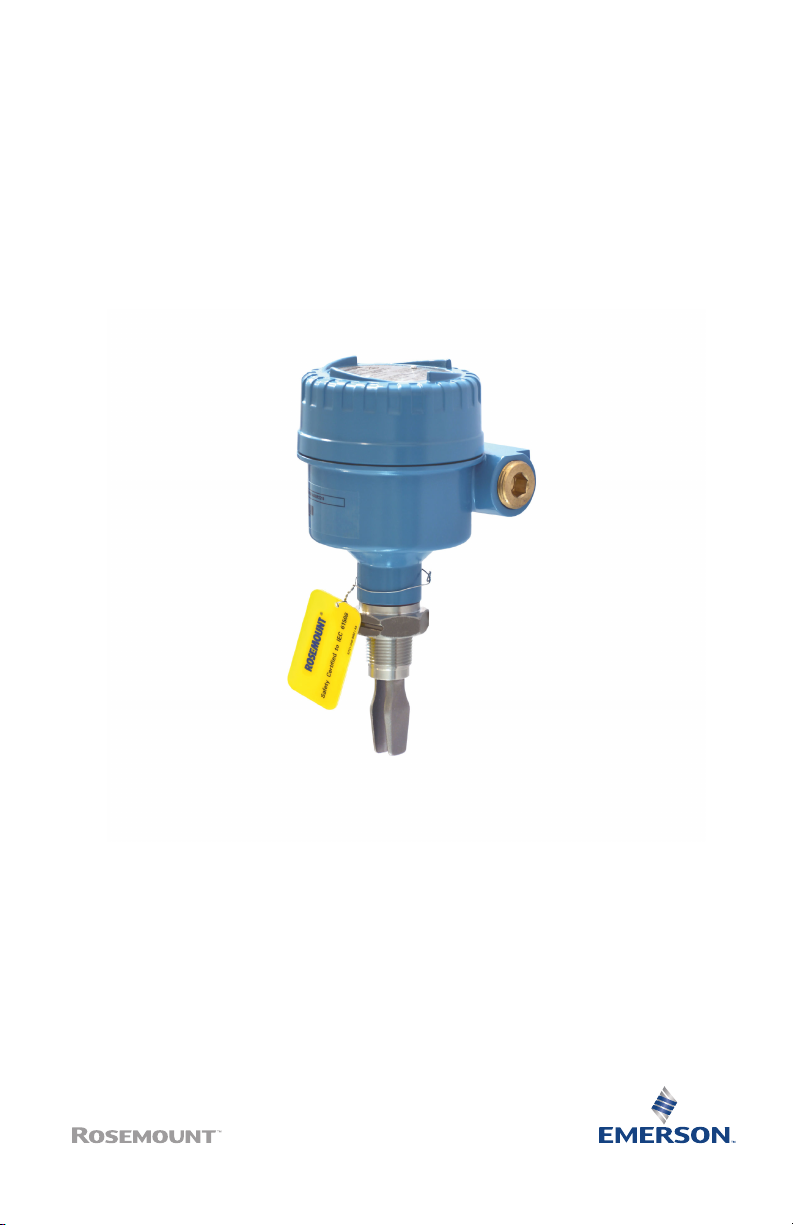
Rosemount™ 2120 Level Switch
Vibrating Fork
Quick Start Guide
March 2022
Page 2

Quick Start Guide March 2022
Contents
About this guide...........................................................................................................................3
Installation................................................................................................................................... 5
Prepare the electrical connections..............................................................................................11
Connect wiring and power up.....................................................................................................26
Configuration.............................................................................................................................30
Operation...................................................................................................................................32
2 Rosemount 2120 Level Switch
Page 3

March 2022 Quick Start Guide
1 About this guide
This Quick Start Guide provides basic guidelines for the Rosemount 2120.
Refer to the Rosemount 2120 Reference Manual for more instructions. The
manual and this guide are also available electronically at
Emerson.com/Rosemount.
1.1 Safety messages
WARNING
Failure to follow safe installation and servicing guidelines could result in
death or serious injury.
Ensure the level switch is installed by qualified personnel and in accordance
with applicable code of practice.
Use the level switch only as specified in this manual. Failure to do so may
impair the protection provided by the level switch.
The weight of a level switch with a heavy flange and extended fork length
may exceed 37 lb. (18 kg). A risk assessment is required before carrying,
lifting, and installing the level switch.
Repair, e.g. substitution of components, etc. may jeopardize safety and is
under no circumstances allowed.
WARNING
Explosions could result in death or serious injury.
Verify the operating atmosphere of the level switch is consistent with the
appropriate hazardous locations certifications.
Before connecting a handheld communicator in an explosive atmosphere,
ensure the instruments are installed in accordance with intrinsically safe or
non-incendive field wiring practices.
In explosion-proof/flameproof and non-incendive installations, do not
remove the housing cover when power is applied to the level switch.
The housing cover must be fully engaged to meet flameproof/explosionproof requirements.
Quick Start Guide 3
Page 4

Quick Start Guide March 2022
WARNING
Electrical shock could cause death or serious injury.
Avoid contact with the leads and terminals. High voltage that may be
present on leads can cause electrical shock.
Ensure the power to the level switch is off, and the lines to any other external
power source are disconnected or not powered while wiring the level switch.
Ensure the wiring is suitable for the electrical current and the insulation is
suitable for the voltage, temperature, and environment.
WARNING
Process leaks could result in death or serious injury.
Ensure the level switch is handled carefully. If the process seal is damaged,
gas might escape from the vessel (tank) or pipe.
WARNING
Physical access
Unauthorized personnel may potentially cause significant damage to and/or
misconfiguration of end users’ equipment. This could be intentional or
unintentional and needs to be protected against.
Physical security is an important part of any security program and
fundamental to protecting your system. Restrict physical access by
unauthorized personnel to protect end users’ assets. This is true for all
systems used within the facility.
CAUTION
Hot surfaces
The flange and process seal may be hot at high process temperatures. Allow
to cool before servicing.
4 Rosemount 2120 Level Switch
Page 5
A
B
A
B
OK
OK
A
B
C
OK OK
OK
March 2022 Quick Start Guide
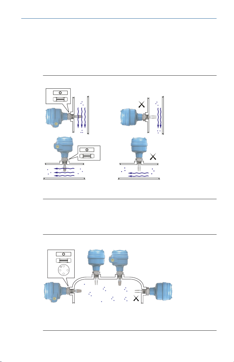
2 Installation
2.1 Fork alignment in a pipe installation
The fork is correctly aligned by positioning the groove or notch as indicated
(Figure 2-1).
Figure 2-1: Correct Fork Alignment for Pipe Installation
A. Tri Clamp process connections have a circular notch
B. Threaded process connections have a groove
2.2 Fork alignment in a vessel (tank) installation
The fork is correctly aligned by positioning the groove or notch as indicated
(Figure 2-2).
Figure 2-2: Correct Fork Alignment for Vessel (Tank) Installation
Quick Start Guide 5
A. Tri Clamp process connections have a circular notch
B.
Threaded process connections have a groove
Flanged process connections have a circular notch
C.
Page 6
A
A
Quick Start Guide March 2022
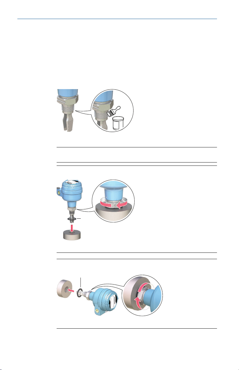
2.3 Mounting the threaded version
2.3.1 Threaded vessel (tank) or pipework connection
Procedure
1. Seal and protect the threads. Use anti-seize paste or PTFE tape
according to site procedures.
A gasket may be used as a sealant for BSPP (G) threaded connections.
2. Screw the level switch into the process connection.
Note
Tighten using the hexagon nut only.
Figure 2-3: Vertical Installation
A. Gasket for BSPP (G) threaded connection
Figure 2-4: Horizontal Installation
6 Rosemount 2120 Level Switch
A. Gasket for BSPP (G) threaded connection
Page 7
A
March 2022 Quick Start Guide
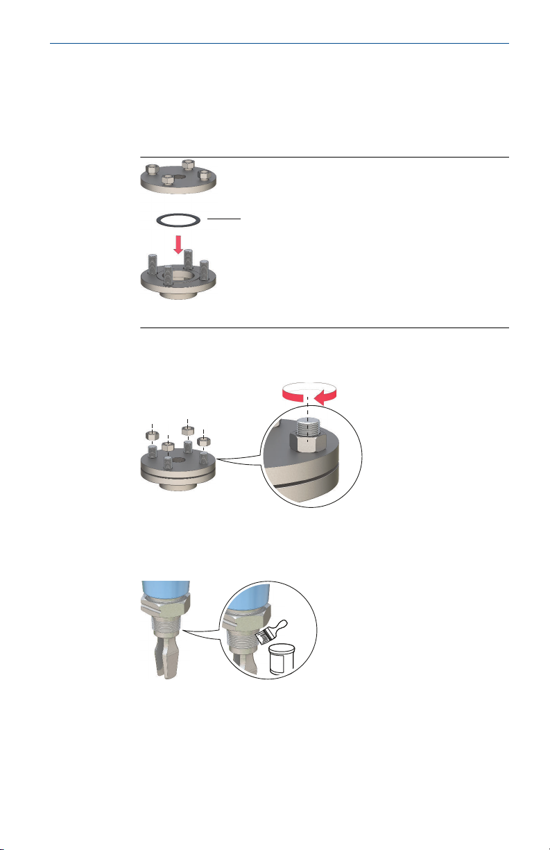
2.3.2 Threaded flange connection
Procedure
1. Place the customer-supplied flange and gasket on the vessel (tank)
nozzle.
A. Gasket (customer supplied)
2. Tighten the bolts and nuts with sufficient torque for the flange and
gasket.
3. Seal and protect the threads. Use anti-seize paste or PTFE tape
according to site procedures.
A gasket may be used as a sealant for BSPP (G) threaded connections.
Quick Start Guide 7
Page 8
A
A
Quick Start Guide March 2022
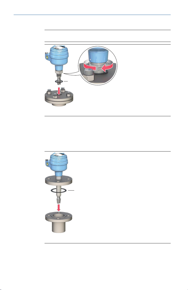
4. Screw the level switch into the flange thread.
Note
Tighten using the hexagon nut only.
A. Gasket for BSPP (G) threaded connection
2.4 Mounting the flanged version
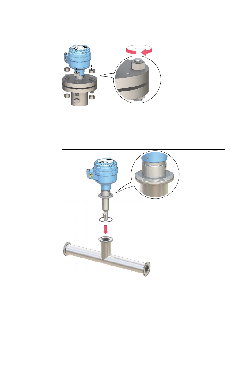
Procedure
1. Lower the level switch into the nozzle.
A. Gasket (customer supplied)
8 Rosemount 2120 Level Switch
Page 9
A
March 2022 Quick Start Guide
2. Tighten the bolts and nuts with sufficient torque for the flange and
gasket.
2.5 Mounting the Tri Clamp version
Procedure
1. Lower the level switch into the flange face.
A. Seal (supplied with Tri Clamp)
Quick Start Guide 9
Page 10
Quick Start Guide March 2022
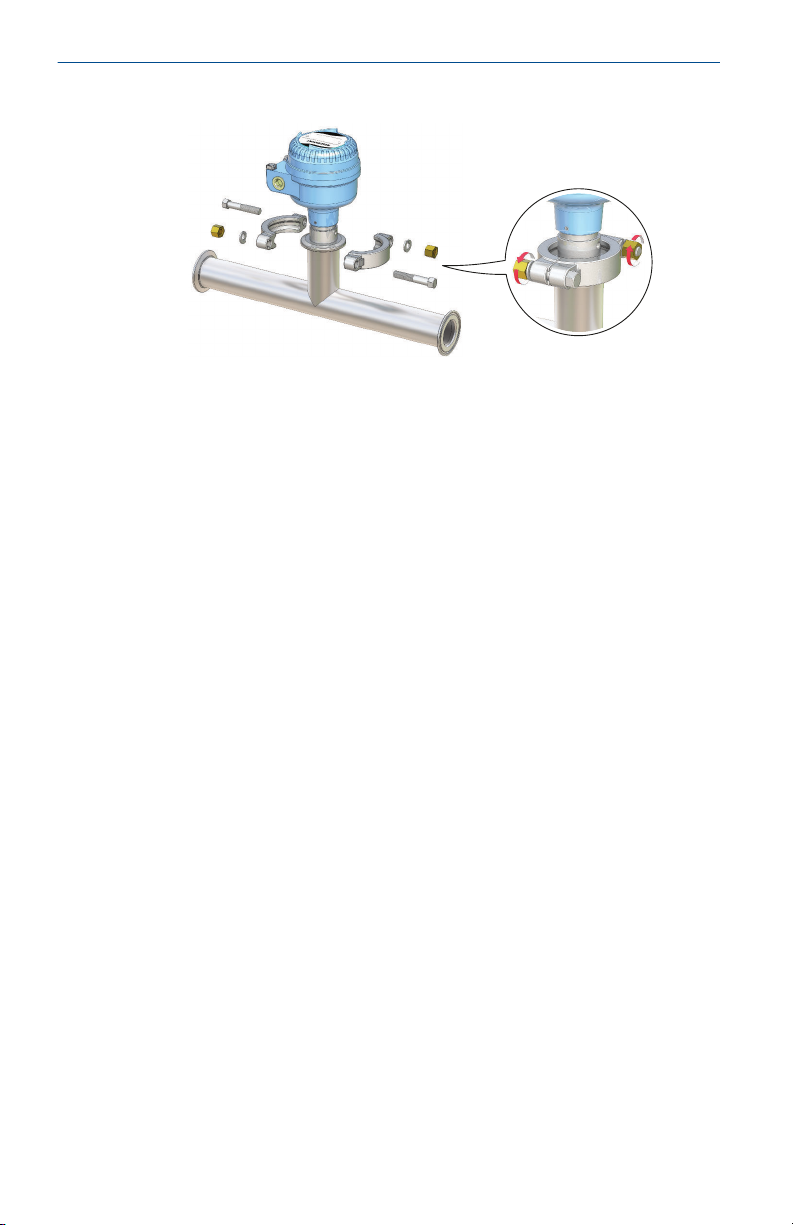
2. Fit the Tri Clamp.
10 Rosemount 2120 Level Switch
Page 11

March 2022 Quick Start Guide
3 Prepare the electrical connections
3.1 Cable selection
Use 26–14 AWG (0.13 to 2.5 mm2) AWG wiring. Twisted-pairs and shielded
wiring is recommended for environments with high EMI (electromagnetic
interference). Two wires can be safely connected to each terminal screw.
3.2 Cable glands/conduits
For intrinsically safe, explosion-proof/flameproof, and dust-proof
installations, only use certified cable glands or conduit entry devices.
Ordinary location installations can use suitably rated cable glands or conduit
entry devices to maintain the Ingress Protection (IP) rating.
Unused conduit entries must always be sealed with a suitably rated
blanking/stopping plug.
Note
Do not run signal wiring in conduit or open trays with power wiring or near
heavy electrical equipment.
3.3 Power supply
The power supply requirements are dependent on the electronics selected.
• Direct load switching: 20 - 60 Vdc or 20 - 264 Vac (50/60 Hz)
• PNP/PLC electronics: 20 - 60 Vdc
• Relay DPCO (Double Pole Changeover) electronics (standard):
20 - 60 Vdc or 20 - 264 Vac (50/60 Hz)
• Relay DPCO electronics (12 Vdc nominal): 9 - 30 Vdc
• NAMUR electronics: 8 Vdc
• 8/16 mA electronics: 24 Vdc
3.4 Hazardous areas
When the device is installed in hazardous areas (classified locations), local
regulations and the conditions-of-use specified in applicable certificates
must be observed. Review the Rosemount 2120 Product Certifications
document for information.
Quick Start Guide 11
Page 12

Quick Start Guide March 2022
3.5 Wiring diagrams
CAUTION
• Before use, check the cable glands and blanking plugs are suitably rated.
• Isolate supply before connecting the switch or removing the electronics.
• The Protective Earth (PE)
earthing system.
terminal must be connected to an external
12 Rosemount 2120 Level Switch
Page 13

1 2 3
LN
0V
I
L
DPST
+V
Fuse 2A(T)R
March 2022 Quick Start Guide
3.5.1 Direct load switching cassette
Figure 3-1: Direct Load Switching (2-wire) Cassette (Red Label) – Code T
R = External load (must be fitted)
N = Neutral
L = Live
Note
A DPST (Double Pole, Single Throw) on/off switch must be fitted for safe
disconnection of the power supply. Fit the DPST switch as near as possible to
the level switch. Keep the DPST switch free of obstructions. Label the DPST
switch to indicate it is the supply disconnection device for the level switch.
Table 3-1: Electrical Parameters
Parameter Value
U 20 - 60 Vdc or 20 - 264 Vac (50/60 Hz)
I
OFF
I
L
I
PK
Quick Start Guide 13
< 4 mA
20 - 500 mA
5 A, 40 ms (inrush)
Page 14

1 2
I
L
R
N
0 VL+ V
F
3
DPST
U
12 V
1 2
I
L
R
N
0 VL+ V
F
3
DPST
< 4 mA
1 2
I
L
R
N
0 VL+ V
F
3
DPST
U
12 V
1 2
I
L
R
N
0 VL+ V
F
3
DPST
< 4 mA
= Load on
= Load off
Quick Start Guide March 2022
Table 3-2: Direct Load Functions
Mode: dry on, high level alarm Mode: wet on, low level alarm
LED on continuously LED flashes every
LED on continuously LED flashes every
second
14 Rosemount 2120 Level Switch
second
Page 15

Wet On Mode
+V
1
2 3 4
O/P 0V
F
March 2022 Quick Start Guide
3.5.2 PNP/PLC cassette
Figure 3-2: PNP/PLC (3-wire) Cassette (Yellow Label) – Code G
F = Fuse 2A(T)
Table 3-3: Electrical Parameters
Parameter Value
U 20 - 60 Vdc
I < 4 mA + I
I
L (OFF)
I
L(MAX)
I
PK
U
OUT(ON)
< 100 μA
0 - 500 mA
5 A, 40 ms (inrush)
U - 2.5 Vdc (20 °C)
U - 2.75 Vdc (-40 to 80 °C)
L
Quick Start Guide 15
Page 16

1 2
-
I/P
PLC
+
3 4
I
L
< 3 V
U
1 2
-
I/P
PLC
+
3 4
I
L
<100 μA
1 2
-
I/P
PLC
+
3 4
I
L
< 3 V
U
1 2
-
I/P
PLC
+
3 4
I
L
<100 μA
1 2
3 4
R
F
< 3 V
U
I
L
1 2
-+
3 4
R
F
I
L
<100 μA
1 2
-
+
3 4
R
F
< 3 V
U
I
L
1 2
-+
3 4
R
F
I
L
<100 μA
Quick Start Guide March 2022
Table 3-4: PNP/PLC Cassette Functions
Mode: dry on, high level alarm Mode: wet on, low level alarm
PLC (positive input)
PNP dc
LED
LED on continuously LED flashes every
LED on continuously LED flashes every
second
16 Rosemount 2120 Level Switch
second
Page 17

LN
0V
Fuse 0.5 (T)
DPST
+V
1
2 3
4
5 6
7
8 9
NC
C NO
NC
C NO
March 2022 Quick Start Guide
3.5.3 Relay DPCO cassette (standard version)
Figure 3-3: Relay DPCO Cassette, Standard Version (Green Label) – Code
V
Note
A DPST (Double Pole, Single Throw) on/off switch must be fitted for safe
disconnection of the power supply. Fit the DPST switch as near as possible to
the level switch. Keep the DPST switch free of obstructions. Label the DPST
switch to indicate it is the supply disconnection device for the level switch.
Table 3-5: Electrical Parameters
Parameter Value
U 20 - 60 Vdc or 20 - 264 Vac (50/60Hz)
I < 6 mA
Quick Start Guide 17
Page 18

NC C NO
NC C NO
NC C NO
NC C NO
NC C NO
NC C NO
NC C NO
NC C NO
Quick Start Guide March 2022
Table 3-6: NC, C, and NO Terminals
Parameter Resistive load Inductive load
cos ϕ 1 0.4
L/R 0 ms 7 ms
I
MAX
U
MAX
ac 250 V 250 V
5 A 3.5 A
dc 30 V 30 V
P
MAX
ac 1250 VA 875 VA
dc 240 W 170 W
Table 3-7: Relay Cassette Functions
Mode: dry on, high level alarm Mode: wet on, low level alarm
LED on continuously LED flashes every
LED on continuously LED flashes every
second
18 Rosemount 2120 Level Switch
second
Page 19

NC
C NO
NC
C NO
0V
Fuse 0.5 (T)
DPST
+V
March 2022 Quick Start Guide
3.5.4 Relay DPCO cassette (12 Vdc nominal version)
Figure 3-4: Relay DPCO Cassette, 12 Vdc Nominal Version (Green Label)
– Code E
Note
A DPST (Double Pole, Single Throw) on/off switch must be fitted for safe
disconnection of the power supply. Fit the DPST switch as near as possible to
the Rosemount 2120. Keep the DPST switch free of obstructions. Label the
DPST switch to indicate it is the supply disconnection device for the
Rosemount 2120.
Table 3-8: Electrical Parameters
Parameter Value
U 9 - 30 Vdc
I < 4 mA
Table 3-9: NC, C, and NO Terminals
Parameter Resistive load Inductive load
cos ϕ 1 0.4
L/R 0 ms 7 ms
I
MAX
U
MAX
P
MAX
Quick Start Guide 19
2 A 1 A
30 V 30 V
60 W 30 W
Page 20

NC C NO
NC C NO
NC C NO
NC C NO
NC C NO
NC C NO
NC C NO
NC C NO
Quick Start Guide March 2022
Table 3-10: Relay Cassette Functions
Mode: dry on, high level alarm Mode: wet on, low level alarm
LED on continuously LED flashes every
second
LED on continuously LED flashes every
second
20 Rosemount 2120 Level Switch
Page 21

A
+
-
March 2022 Quick Start Guide
3.5.5 NAMUR cassette
Figure 3-5: NAMUR Cassette (Light Blue Label) – Code K
A. A certified intrinsically safe isolating amplifier to IEC 60947-5-6
Note
• This cassette is suitable for Intrinsically Safe (IS) applications and requires
a certified isolating barrier. See the Rosemount 2120 Product
Certifications document for Intrinsically Safe approvals.
• This electronics cassette is also suitable for non-hazardous (safe) area
applications.
• It can only be interchanged with the 8/16 mA cassette.
• Do not exceed 8 Vdc.
Table 3-11: Electrical Parameters
Parameter Value
I
ON
I
OFF
I
FAULT
Quick Start Guide 21
2.2 - 2.5 mA
0.8 - 1.0 mA
< 1.0 mA
Page 22

1 2
> 2.2 mA
(-) (+)
1 2
< 1.0 mA
(-) (+)
1 2
> 2.2 mA
(-) (+)
1 2
< 1.0 mA
(-) (+)
Quick Start Guide March 2022
Table 3-12: NAMUR Cassette Functions
Mode: dry on, high level alarm Mode: wet on, low level alarm
LED on continuously LED flashes every
22 Rosemount 2120 Level Switch
second
LED on continuously LED flashes every
second
Page 23

1 2
3
A
+
-
March 2022 Quick Start Guide
3.5.6 8/16 mA cassette
Figure 3-6: 8/16 mA Cassette (Dark Blue Label) – Code H
A. A certified intrinsically safe isolating amplifier to IEC 60947-5-6
Note
• This cassette is suitable for Intrinsically Safe (IS) applications and requires
a certified isolating barrier. See the Rosemount 2120 Product
Certifications document for Intrinsically Safe approvals.
• This electronics cassette is also suitable for non-hazardous (safe) area
applications. In this case, U = 11 - 36 Vdc.
• It can only be interchanged with a NAMUR cassette.
Table 3-13: Electrical Parameters
Parameter Value
U 24 Vdc Nominal
I
ON
I
OFF
I
FAULT
Quick Start Guide 23
15 - 17 mA
7.5 - 8.5 mA
< 3.7 mA
Page 24

2
(-) (+)
31
> 15 mA
2
(-) (+)
31
< 8.5 mA
2
(-) (+)
31
> 15 mA
2
(-) (+)
31
< 8.5 mA
Quick Start Guide March 2022
Table 3-14: 8/16 mA Cassette Functions
Mode: dry on, high level alarm Mode: wet on, low level alarm
LED on continuously LED flashes every
second
24 Rosemount 2120 Level Switch
LED on continuously LED flashes every
second
Page 25

B
A
CC
D
B
A
March 2022 Quick Start Guide
3.6 Grounding
Make sure grounding is done according to national and local electrical
codes. Failure to do so may impair the protection provided by the
equipment.
3.6.1 Signal cable shield grounding
Make sure the instrument cable shield is:
• Trimmed close and insulated from touching the housing.
• Continuously connected throughout the segment.
• Connected to a good earth ground at the power supply end.
Figure 3-7: Signal Cable Shield Grounding at Power Supply End
A. Trim shield and insulate
B. Minimize distance
C.
Trim shield
D. Connect shield back to the power supply ground
3.6.2 Grounding the housing
The most effective grounding method for the metal housing is a direct
connection to earth ground with minimal impedance. Housings with NPT
conduit entries do not have an earth ground point and must use the fork
earth.
Figure 3-8: Ground Screws
A. External ground screw
Quick Start Guide 25
Page 26

Quick Start Guide March 2022
4 Connect wiring and power up
Procedure
1. Verify the power supply is disconnected.
2. Remove the field terminals cover.
In an explosion-proof/flameproof installation, do not remove the
level switch cover when power is applied to the unit. The cover must
also not to be removed in extreme environmental conditions.
• Versions of the Rosemount 2120 with a metal housing are
explosion-proof/flameproof. They have a cover-lock to be
undone first.
• Versions of the Rosemount 2120 with a glass-filled-nylon housing
are not explosion-proof/flameproof. They do not have a coverlock.
3. Remove the plastic plugs.
Versions of the Rosemount 2120 with a glass-filled-nylon housing do
not have plastic plugs fitted.
26 Rosemount 2120 Level Switch
Page 27

¾-in. ANPTM20 x 1.5
M20
¾-in. ANPTM20 x 1.5
M20
March 2022 Quick Start Guide
4. Pull cables through the cable gland/conduits.
• Cassettes with a single terminal only require one cable.
Identification of thread size and type:
• Cassettes with two or more terminals may require more than one
cable.
5. Connect the cable wires (see
Wiring diagrams for other cassettes).
Metal housing:
Glass-filled-nylon housing:
6. Ensure proper grounding.
Quick Start Guide 27
Page 28

Quick Start Guide March 2022
7. Tighten the cable glands.
Apply PTFE tape or other sealant to the threads.
Metal housing:
Glass-filled-nylon housing:
Note
Make sure to arrange the wiring with a drip loop.
28 Rosemount 2120 Level Switch
Page 29

March 2022 Quick Start Guide
8. Plug and seal the unused conduit connection to avoid moisture and
dust accumulation inside the housing.
Apply PTFE tape or other sealant to the threads.
Metal housing:
Glass-filled-nylon housing:
9. Attach and tighten the cover.
Make sure the cover is fully engaged.
10. Required for explosion-proof/flameproof installations only:
The cover must be fully engaged to comply with explosion-proof
requirements.
11. Re-lock the cover.
12. Connect the power supply.
Quick Start Guide 29
Page 30

OPERATION MODE
Dry On Mode
Dry
Wet
Wet On Mode
Dry
Wet
Dry On Wet On
Seconds Delay
0.3 0.3
3
3
0
1
0
1
3
30
10
1
1 2
3
OUT
+
-
4
PLC/PNP
Isolate Supply
Before Removing
A B
Quick Start Guide March 2022
5 Configuration
5.1 Output mode and time delay
All electronics cassettes have a rotating switch for setting the output to be
"Dry On" (on when the fork is sufficiently dry) or "Wet On" (on when the fork
is sufficiently wet).
The electronics uses hysteresis to help prevent constant switching of the
output from dry-to-wet and wet-to-dry states due to splashing or
intermediate conditions. To further prevent false switching, the rotating
switch also sets a time delay of up to 30 seconds before the output changes.
A small cut-out in the rotating switch indicates the present mode and time
delay.
Figure 5-1: Top-down View: Example Cassette Inside Housing
A. 'Heartbeat' LED
B. Rotating switch for setting output mode and time delay
The recommended mode for high level alarm installations is the "Dry On"
mode (Figure 5-2).
30 Rosemount 2120 Level Switch
Page 31

Dry On Wet On
Seconds Delay
0.3 0
.3
3
30
1
0
1
3
30
10
1
A
Dry On Wet On
Seconds Delay
0.3 0
.3
30
10
3
30
10
1
3
1
A
March 2022 Quick Start Guide
Figure 5-2: Typical Settings for High Level Applications
A. Mode “Dry On” and 1 second time delay
The "Wet On" mode is recommended for low level alarm installations (Figure
5-3).
Figure 5-3: Typical Settings for Low Level Applications
A. Mode “Wet On” and 1 second time delay
5.1.1 Set the mode switch and switching time delay
Procedure
1. Select “Dry on” or “Wet on” mode.
2.
Select 0.3, 1, 3, 10, or 30 seconds for the delay before switching
output state.
Note
There is a five second delay before changes to the mode and time
delay become active.
Quick Start Guide 31
Page 32

Quick Start Guide March 2022
6 Operation
6.1 LED indication status
Table 6-1 shows the different operation statuses and how they are indicated
by the LED.
Table 6-1: LED Indications
LED flash rate Switch status
Continuous Output state is on.
1 every second Output state is off.
1 every 2 seconds Uncalibrated.
1 every 4 seconds Load fault; load current too high; load
2 times / second Indication of successful calibration.
3 times / second Internal PCB fault.
Off Problem (e.g. supply).
short circuit.
32 Rosemount 2120 Level Switch
Page 33

March 2022 Quick Start Guide
Quick Start Guide 33
Page 34

Quick Start Guide March 2022
34 Rosemount 2120 Level Switch
Page 35

March 2022 Quick Start Guide
Quick Start Guide 35
Page 36

*00825-0100-4030*
00825-0100-4030, Rev. GB
Quick Start Guide
March 2022
For more information:
©
2022 Emerson. All rights reserved.
Emerson Terms and Conditions of Sale are
available upon request. The Emerson logo
is a trademark and service mark of
Emerson Electric Co. Rosemount is a mark
of one of the Emerson family of
companies. All other marks are the
property of their respective owners.
Emerson.com
 Loading...