

Page 1
Rosemount™ 2120 Level Switch
Vibrating Fork
Reference Manual
00809-0100-4030, Rev FA
December 2016
Page 2

Page 3

Reference Manual
00809-0100-4030, Rev FA
Contents
1Section 1: Introduction
2Section 2: Installation
Contents
December 2016
1.1 Using this manual . . . . . . . . . . . . . . . . . . . . . . . . . . . . . . . . . . . . . . . . . . . . . . . . . . . . . . . . . . . . . . . . . 1
1.2 Models covered . . . . . . . . . . . . . . . . . . . . . . . . . . . . . . . . . . . . . . . . . . . . . . . . . . . . . . . . . . . . . . . . . . . 1
1.3 Level switch overview . . . . . . . . . . . . . . . . . . . . . . . . . . . . . . . . . . . . . . . . . . . . . . . . . . . . . . . . . . . . . . 1
1.3.1 Features list . . . . . . . . . . . . . . . . . . . . . . . . . . . . . . . . . . . . . . . . . . . . . . . . . . . . . . . . . . . . . . . . . 1
1.3.2 Measurement principle . . . . . . . . . . . . . . . . . . . . . . . . . . . . . . . . . . . . . . . . . . . . . . . . . . . . . . . 3
1.3.3 Short fork technology . . . . . . . . . . . . . . . . . . . . . . . . . . . . . . . . . . . . . . . . . . . . . . . . . . . . . . . . 3
1.3.4 Special features. . . . . . . . . . . . . . . . . . . . . . . . . . . . . . . . . . . . . . . . . . . . . . . . . . . . . . . . . . . . . . 4
1.4 Product recycling and disposal . . . . . . . . . . . . . . . . . . . . . . . . . . . . . . . . . . . . . . . . . . . . . . . . . . . . . . 4
2.1 Safety messages. . . . . . . . . . . . . . . . . . . . . . . . . . . . . . . . . . . . . . . . . . . . . . . . . . . . . . . . . . . . . . . . . . . 5
2.2 Considerations before installation . . . . . . . . . . . . . . . . . . . . . . . . . . . . . . . . . . . . . . . . . . . . . . . . . . . 6
2.2.1 Safety considerations . . . . . . . . . . . . . . . . . . . . . . . . . . . . . . . . . . . . . . . . . . . . . . . . . . . . . . . . 6
2.2.2 Environmental considerations . . . . . . . . . . . . . . . . . . . . . . . . . . . . . . . . . . . . . . . . . . . . . . . . . 6
2.2.3 Application considerations. . . . . . . . . . . . . . . . . . . . . . . . . . . . . . . . . . . . . . . . . . . . . . . . . . . . 7
2.2.4 Installation considerations . . . . . . . . . . . . . . . . . . . . . . . . . . . . . . . . . . . . . . . . . . . . . . . . . . . . 8
2.2.5 Installation recommendations. . . . . . . . . . . . . . . . . . . . . . . . . . . . . . . . . . . . . . . . . . . . . . . . 10
2.2.6 Installation examples . . . . . . . . . . . . . . . . . . . . . . . . . . . . . . . . . . . . . . . . . . . . . . . . . . . . . . . . 13
2.3 Installation procedures. . . . . . . . . . . . . . . . . . . . . . . . . . . . . . . . . . . . . . . . . . . . . . . . . . . . . . . . . . . . 14
2.3.1 Mechanical. . . . . . . . . . . . . . . . . . . . . . . . . . . . . . . . . . . . . . . . . . . . . . . . . . . . . . . . . . . . . . . . . 14
2.3.2 Correct fork alignment . . . . . . . . . . . . . . . . . . . . . . . . . . . . . . . . . . . . . . . . . . . . . . . . . . . . . . 15
2.3.3 Tightening the threaded level switch . . . . . . . . . . . . . . . . . . . . . . . . . . . . . . . . . . . . . . . . . . 17
2.3.4 Insulation . . . . . . . . . . . . . . . . . . . . . . . . . . . . . . . . . . . . . . . . . . . . . . . . . . . . . . . . . . . . . . . . . . 17
2.4 Setting the mode switch and switching time delay. . . . . . . . . . . . . . . . . . . . . . . . . . . . . . . . . . . . 18
2.5 LED indication. . . . . . . . . . . . . . . . . . . . . . . . . . . . . . . . . . . . . . . . . . . . . . . . . . . . . . . . . . . . . . . . . . . . 19
2.6 Electrical installation . . . . . . . . . . . . . . . . . . . . . . . . . . . . . . . . . . . . . . . . . . . . . . . . . . . . . . . . . . . . . . 20
2.6.1 Direct load switching electronics cassette. . . . . . . . . . . . . . . . . . . . . . . . . . . . . . . . . . . . . . 20
2.6.2 PNP/PLC electronics cassette . . . . . . . . . . . . . . . . . . . . . . . . . . . . . . . . . . . . . . . . . . . . . . . . . 22
2.6.3 Relay output electronics cassette (standard version) . . . . . . . . . . . . . . . . . . . . . . . . . . . . 23
2.6.4 Relay output electronics cassette (12 Vdc nominal version) . . . . . . . . . . . . . . . . . . . . . . 24
Contents
2.6.5 NAMUR electronics cassette . . . . . . . . . . . . . . . . . . . . . . . . . . . . . . . . . . . . . . . . . . . . . . . . . 25
2.6.6 8/16 mA electronics cassette . . . . . . . . . . . . . . . . . . . . . . . . . . . . . . . . . . . . . . . . . . . . . . . . . 26
i
Page 4

Contents
December 2016
Reference Manual
00809-0100-4030, Rev FA
3Section 3: Service and Troubleshooting
3.1 Safety messages. . . . . . . . . . . . . . . . . . . . . . . . . . . . . . . . . . . . . . . . . . . . . . . . . . . . . . . . . . . . . . . . . . 27
3.2 Magnetic test point . . . . . . . . . . . . . . . . . . . . . . . . . . . . . . . . . . . . . . . . . . . . . . . . . . . . . . . . . . . . . . . 28
3.3 Inspection . . . . . . . . . . . . . . . . . . . . . . . . . . . . . . . . . . . . . . . . . . . . . . . . . . . . . . . . . . . . . . . . . . . . . . . 29
3.4 Maintenance. . . . . . . . . . . . . . . . . . . . . . . . . . . . . . . . . . . . . . . . . . . . . . . . . . . . . . . . . . . . . . . . . . . . . 29
3.5 Spare parts . . . . . . . . . . . . . . . . . . . . . . . . . . . . . . . . . . . . . . . . . . . . . . . . . . . . . . . . . . . . . . . . . . . . . . 30
3.6 Troubleshooting . . . . . . . . . . . . . . . . . . . . . . . . . . . . . . . . . . . . . . . . . . . . . . . . . . . . . . . . . . . . . . . . . 30
3.7 Service support. . . . . . . . . . . . . . . . . . . . . . . . . . . . . . . . . . . . . . . . . . . . . . . . . . . . . . . . . . . . . . . . . . . 30
3.8 Replacement and calibration of electronic cassettes . . . . . . . . . . . . . . . . . . . . . . . . . . . . . . . . . . 31
3.8.1 Replacement sequence. . . . . . . . . . . . . . . . . . . . . . . . . . . . . . . . . . . . . . . . . . . . . . . . . . . . . . 31
3.8.2 Calibration sequence . . . . . . . . . . . . . . . . . . . . . . . . . . . . . . . . . . . . . . . . . . . . . . . . . . . . . . . . 32
4Appendix A: Specifications and Reference Data
A.1 Specifications . . . . . . . . . . . . . . . . . . . . . . . . . . . . . . . . . . . . . . . . . . . . . . . . . . . . . . . . . . . . . . . . . . . . 35
A.1.1 General . . . . . . . . . . . . . . . . . . . . . . . . . . . . . . . . . . . . . . . . . . . . . . . . . . . . . . . . . . . . . . . . . . . . 35
A.1.2 Mechanical. . . . . . . . . . . . . . . . . . . . . . . . . . . . . . . . . . . . . . . . . . . . . . . . . . . . . . . . . . . . . . . . . 35
A.1.3 Functional . . . . . . . . . . . . . . . . . . . . . . . . . . . . . . . . . . . . . . . . . . . . . . . . . . . . . . . . . . . . . . . . . 35
A.1.4 Performance . . . . . . . . . . . . . . . . . . . . . . . . . . . . . . . . . . . . . . . . . . . . . . . . . . . . . . . . . . . . . . . 37
A.1.5 Electrical. . . . . . . . . . . . . . . . . . . . . . . . . . . . . . . . . . . . . . . . . . . . . . . . . . . . . . . . . . . . . . . . . . . 37
A.2 Dimensional drawings . . . . . . . . . . . . . . . . . . . . . . . . . . . . . . . . . . . . . . . . . . . . . . . . . . . . . . . . . . . . 39
A.3 Ordering information . . . . . . . . . . . . . . . . . . . . . . . . . . . . . . . . . . . . . . . . . . . . . . . . . . . . . . . . . . . . . 46
A.3.1 Spare parts and accessories . . . . . . . . . . . . . . . . . . . . . . . . . . . . . . . . . . . . . . . . . . . . . . . . . . 50
5Appendix B: Product Certifications
B.1 European directive information . . . . . . . . . . . . . . . . . . . . . . . . . . . . . . . . . . . . . . . . . . . . . . . . . . . . 51
B.2 Hygienic approvals & compliances (surface finish codes 3, 4, 7, and 8) . . . . . . . . . . . . . . . . . . 51
B.3 Overfill approval. . . . . . . . . . . . . . . . . . . . . . . . . . . . . . . . . . . . . . . . . . . . . . . . . . . . . . . . . . . . . . . . . . 51
B.4 Marine approvals . . . . . . . . . . . . . . . . . . . . . . . . . . . . . . . . . . . . . . . . . . . . . . . . . . . . . . . . . . . . . . . . . 51
B.5 Drinking water approval . . . . . . . . . . . . . . . . . . . . . . . . . . . . . . . . . . . . . . . . . . . . . . . . . . . . . . . . . . . 51
B.6 NAMUR approval . . . . . . . . . . . . . . . . . . . . . . . . . . . . . . . . . . . . . . . . . . . . . . . . . . . . . . . . . . . . . . . . . 51
B.7 Ordinary location certifications. . . . . . . . . . . . . . . . . . . . . . . . . . . . . . . . . . . . . . . . . . . . . . . . . . . . . 51
B.8 Canadian Registration Number. . . . . . . . . . . . . . . . . . . . . . . . . . . . . . . . . . . . . . . . . . . . . . . . . . . . . 51
B.9 Safety Integrity Level (SIL) . . . . . . . . . . . . . . . . . . . . . . . . . . . . . . . . . . . . . . . . . . . . . . . . . . . . . . . . . 51
B.10 Hazardous locations certifications . . . . . . . . . . . . . . . . . . . . . . . . . . . . . . . . . . . . . . . . . . . . . . . . . 52
B.10.1 American and Canadian approvals. . . . . . . . . . . . . . . . . . . . . . . . . . . . . . . . . . . . . . . . . . . . 52
B.10.2 European approvals . . . . . . . . . . . . . . . . . . . . . . . . . . . . . . . . . . . . . . . . . . . . . . . . . . . . . . . . 59
B.10.3 International approvals . . . . . . . . . . . . . . . . . . . . . . . . . . . . . . . . . . . . . . . . . . . . . . . . . . . . . 62
B.11Hygienic installations . . . . . . . . . . . . . . . . . . . . . . . . . . . . . . . . . . . . . . . . . . . . . . . . . . . . . . . . . . . . . 62
ii
Contents
Page 5
Reference Manual
NOTICE
00809-0100-4030, Rev FA
Rosemount™ 2120 Level Switch
Vibrating Fork
Read this manual before working with the product. For personal and system safety, and for optimum
product performance, make sure you thoroughly understand the contents before installing, using, or
maintaining this product.
For technical assistance, contacts are listed below:
Customer Central
Technical support, quoting, and order-related questions.
Americas 1 800 999 9307
Europe +41 (0) 41 768 6111
Middle east +971 4 811 8100
Asia +65 6777 8211
North American Response Center
Equipment service needs.
1-800-654-7768 (24 hours — includes Canada)
Outside of these areas, contact your local Emerson
™
representative.
Title Page
December 2016
The products described in this document are NOT designed for nuclear-qualified applications.
Using non-nuclear qualified products in applications that require nuclear-qualified hardware or
products may cause inaccurate readings.
For information on Rosemount nuclear-qualified products, contact your local Emerson sales
representative.
Title Page
v
Page 6

Title Page
December 2016
Reference Manual
00809-0100-4030, Rev FA
Failure to follow these installation guidelines could result in death or serious injury.
Make sure only qualified personnel perform the installation.
Use the Rosemount 2120 Level Switch (“level switch”) only as specified in this manual.
Failure to do so may impair the protection provided by the equipment.
The weight of the level switch with a heavy flange and extended fork length may exceed
37 lb. (18 kg). A risk assessment is required to be done before carrying, lifting, and installing
the level switch.
Explosions could result in death or serious injury.
Do not remove the level switch cover in explosive atmospheres when the circuit is alive.
The level switch cover must be fully engaged and locked to meet explosion-proof
requirements.
Verify the operating environment of the level switch is consistent with the appropriate
hazardous locations certifications.
Review Appendix B: Product Certifications for special conditions and safety instructions
associated with a hazardous location installation.
Electrical shock can result in death or serious injury.
If the level switch is installed in a high-voltage environment and a fault or installation error
occurs, high voltage may be present on the sensor leads and terminals.
Use extreme caution when making contact with the leads and terminals.
Make sure the main power to the level switch is off and the lines to any other external power
source are disconnected or not powered while wiring the level switch.
Ensure the wiring is suitable for the electrical current and the insulation is suitable for the
voltage, temperature, and environment.
External surfaces may be hot.
Care must be taken to avoid possible burns. The flange and process seal may also be hot at
high process temperatures. Allow to cool before servicing.
Process leaks could result in death or serious injury.
Install and tighten process connection before applying pressure.
Do not attempt to loosen the process connection while the level switch is in service.
Make sure that the level switch is handled carefully. If the process seal is damaged, gas might
escape from the tank.
Any substitution of non-recognized parts may jeopardize safety and is under no
circumstances allowed.
Unauthorized changes to the product are strictly prohibited as they may unintentionally and
unpredictably alter performance and jeopardize safety.
Unauthorized changes that interfere with the integrity of the welds or flanges, such as
making additional perforations, compromise product integrity and safety. Equipment
ratings and certifications are no longer valid on any products that have been damaged or
modified without the prior written permission of Emerson. Any continued use of product
that has been damaged or modified without the written authorization is at the customer’s
sole risk and expense.
vi
Title Page
Page 7

Reference Manual
00809-0100-4030, Rev FA
Section 1 Introduction
1.1 Using this manual
The sections in this manual provide information on installing, operating, and maintaining the
Rosemount
Section 2: Installation contains mechanical and electrical installation instructions.
Section 3: Service and Troubleshooting covers basic maintenance guidelines and troubleshooting
techniques for the most common operating problems.
Appendix A: Specifications and Reference Data supplies reference and specification data as well as
ordering information.
Appendix B: Product Certifications contains safety approval information and approval drawings.
1.2 Models covered
™
2120 Level Switch – Vibrating Fork. The sections are organized as follows:
Introduction
December 2016
All models of the Rosemount 2120 Level Switch (“level switch”) are covered in this manual.
1.3 Level switch overview
1.3.1 Features list
Designed for use in process temperatures of –40 to 302 °F (–40 to 150 °C)
Based on vibrating short fork technology, the level switch is suitable for many liquid applications
Virtually unaffected by flow, bubbles, turbulence, foam, vibration, solids content, coating products,
liquid properties, and product variations
A ‘heartbeat’ LED indicates its operating state. The LED also flashes when the switch output is ‘off’ and
is constantly lit when 'on'
‘Fast drip’ fork design gives quicker response time, especially with viscous liquids. Rapid wet-to-dry
and dry-to-wet time setting for highly responsive switching
Adjustable switching delay prevents false switching in turbulent or splashing applications
Fork shape is optimized for polishing to meet hygienic requirements. There are mechanical- and
electro-polishing options
Magnetic test-point for easy functional test
No moving parts or crevices for virtually no maintenance
No need for calibration and requires minimum installation procedures
Easy terminal access and electrical protections (see page 37)
Short fork length with extensions up to 157.5 in. (4 m)
General area, explosion-proof/flameproof and intrinsically safe options
Tri Clamp process connections are available as hygienically certified to 3-A
and compliant with FDA and ASME-BPE
®
and EHDEG,
Introduction
This combination of features makes the Rosemount 2120 Level Switch an ideal choice for a wide variety
of challenging applications in the chemical, power generation, and oil and gas industries.
1
Page 8

Introduction
2
1
2
0
V
i
b
r
a
t
i
n
g
F
o
r
k
L
e
v
e
l
S
w
i
t
c
h
w
w
w
.
r
o
s
e
m
o
u
n
t
.
c
o
m
2
1
2
0
V
i
b
r
a
t
i
n
g
F
o
r
k
L
e
v
e
l
S
w
i
t
c
h
w
w
w
.
r
o
s
e
m
o
u
n
t
.
c
o
m
December 2016
Figure 1-1. Rosemount 2120 Application Examples
Overfill protection
Spillage caused by overfilling can be hazardous to people and the environment, resulting in lost product
and potentially high clean up costs.
High and low level alarm
2
1
2
0
V
i
b
r
a
t
i
n
w
g
ww
F
o
r
.
k
r
o
L
s
e
e
v
m
e
l
o
S
u
w
n
i
t
t
.
c
c
h
o
m
2
1
2
0
V
i
b
r
a
t
i
n
w
g
ww
F
o
r
.
k
r
o
L
s
e
e
v
m
e
l
o
S
u
w
n
i
t
t
.
c
c
h
o
m
Maximum and minimum level detection in tanks containing different types of liquids are ideal
applications. The Rosemount 2120 Level Switch is robust and operates continuously across the process
temperature range of –40 to 302 °F (–40 to 150 °C) and operating pressures of up to 1450 psig (100
barg), making it perfect for use as a high or low level alarm. It is common practice to have an independent
high level alarm switch as a backup to an installed level device in case of primary failure.
Reference Manual
00809-0100-4030, Rev FA
w
w
w
.
r
o
s
e
2
m
1
2
o
0
u
n
V
t
i
b
.
c
r
o
a
m
t
i
n
g
F
o
r
k
L
e
v
e
l
S
w
it
c
h
Pump control (limit detection)
Batch processing tanks often contain stirrers and agitators to ensure mixing and product ‘fluidity’. The
st anda rd us er s elec tabl e ti me de lay, fro m 0.3 to 30 seconds, virtually eliminates the risk of false switching
from splashing.
2
1
2
0
V
i
b
r
a
t
i
n
w
g
ww.
Fo
r
k
r
o
L
s
e
e
v
m
e
l
o
S
u
w
n
i
t
t
.
c
c
h
o
m
Pump protection or empty pipe detection
With the fork projecting only 2 in. (50 mm) (dependent on connection type), the Rosemount 2120 can
be installed in small diameter pipes. Short forks mean minimum intrusion on the wetside and allow for
simple, low cost installation at any angle into pipes or tanks. By selecting the option of direct load
switching or relay electronics, the Rosemount 2120 is ideal for reliable pump control and can be used to
protect against pumps running dry.
Wireless applications
The advent of wireless communications allows process plant managers to save up to 90% on installation
cost compared with wired technologies. More data can be collected at central locations than has ever
been possible before. The Rosemount 2120 can be used with a Rosemount 702 Wireless Discrete
Transmitter to enable these benefits for your applications.
w
w
w
.
r
o
s
e
2
m
1
2
o
0
u
n
V
t
i
b
.
c
r
o
a
m
t
i
n
g
Fo
r
k
L
e
ve
l
S
w
i
t
c
h
Hygienic applications
With the highly polished forks option providing a surface finish (Ra) better than 0.4 μm, the Rosemount
2120 meets the most stringent hygienic requirements used in food and beverage, and pharmaceutical
applications. The Rosemount 2120 is robust enough to easily withstand CIP (Clean-In- Place) and SIP
(Steam-In-Place) cleaning routines.
2
Introduction
Page 9

Reference Manual
F
B
A
G
H
C
I
J
E
D
00809-0100-4030, Rev FA
1.3.2 Measurement principle
The level switch is designed using the principle of a tuning fork. A piezo-electric crystal oscillates the
forks at their natural frequency. Changes to this frequency are continuously monitored. The frequency of
the vibrating fork sensor changes depending on the medium in which it is immersed. The denser the
liquid, the lower the frequency.
When used as a low level alarm, the liquid in the tank or pipe drains down past the fork, causing a
change of natural frequency that is detected by the electronics and switches the output state.
When the level switch is used as a high level alarm, the liquid rises in the tank or pipe making contact
with the fork and causing the output state to switch.
1.3.3 Short fork technology
The natural frequency (~1400 Hz) of the fork avoids interference from plant vibration that may cause
false switching. This allows for minimum intrusion into the tank or pipe through the use of a short fork.
Using short fork technology, the Rosemount 2120 Level Switch can be used in almost all liquid
applications. Extensive research has maximized the operational effectiveness of the fork design, making
it suitable for most liquids including coating liquids, aerated liquids, and slurries.
Introduction
December 2016
Figure 1-2. Rosemount 2120 Features
A. Visible heartbeat LED G. Wetted material in 316/316L SST, solid Alloy C and Alloy C-276,
B. Mode switch, adjustable time delay or ECTFE-coated 316/316L SST
C. Housings in glass-filled nylon, aluminum, or 316 SST H. Short fork length or extensions up to 157.5-in. (4 m)
D. Magnetic test point I. Two cable/ conduit entries
E. Threaded, flanged, or Tri Clamp connections J. Direct Load, Relay DPCO, PLC/PNP, NAMUR,
F. ‘Fast drip’ fork design or 8/16 mA electronics
Introduction
3
Page 10

Introduction
December 2016
1.3.4 Special features
Heartbeat LED
The Rosemount 2120 Level Switch has a ‘heartbeat’ LED indicating its status, which can be seen at all
times and from all angles through a lens in the cover of non-metal housings. The LED flashes when the
switch output is ‘off’ and is constantly lit when 'on'.
Fork design
The “fast drip” fork design draws liquid away from the fork tips when mounted horizontally, and together
with a short switching delay, allows the Rosemount 2120 Level Switch to react quickly and with greater
sensitivity to density variations.
Mode switch and adjustable time delay
A mode switch allows the Rosemount 2120 to be set to switch from wet to dry (typically for low level
alarm) or from dry to wet (typically for high level alarm). There is also a user-selectable time delay (0.3, 1,
3, 10, or 30 s) to virtually eliminate the risk of false switching in turbulent or splashing applications.
Magnetic test point
Reference Manual
00809-0100-4030, Rev FA
A magnetic test-point is located on the side of the housing, allowing the user to perform a functional test
of the Rosemount 2120 and the system connected to it. Holding a magnet to the test-point causes the
output to change state.
Electrical hookup
The terminal blocks extend above the housing and give easy terminal access. Electrical protections
(see page 37) make electrical hook-up safe and easy.
1.4 Product recycling and disposal
Recycling of equipment and packaging should be taken into consideration. The product and packaging
should be disposed of in accordance with local and national legislation.
4
Introduction
Page 11

Reference Manual
00809-0100-4030, Rev FA
Section 2 Installation
Safety messages . . . . . . . . . . . . . . . . . . . . . . . . . . . . . . . . . . . . . . . . . . . . . . . . . . . . . . . . . . . . . . . . . . page 5
Considerations before installation . . . . . . . . . . . . . . . . . . . . . . . . . . . . . . . . . . . . . . . . . . . . . . . . . . page 6
Installation procedures . . . . . . . . . . . . . . . . . . . . . . . . . . . . . . . . . . . . . . . . . . . . . . . . . . . . . . . . . . . . page 14
Setting the mode switch and switching time delay . . . . . . . . . . . . . . . . . . . . . . . . . . . . . . . . . . . . page 18
LED indication . . . . . . . . . . . . . . . . . . . . . . . . . . . . . . . . . . . . . . . . . . . . . . . . . . . . . . . . . . . . . . . . . . . . page 19
Electrical installation . . . . . . . . . . . . . . . . . . . . . . . . . . . . . . . . . . . . . . . . . . . . . . . . . . . . . . . . . . . . . . page 20
2.1 Safety messages
Procedures and instructions in this manual may require special precautions to ensure the safety of the
personnel performing the operations. Information that raises potential safety issues is indicated by a
caution symbol ( ). The external hot surface symbol ( ) is used when a surface is hot and care must be
taken to avoid possible burns. If there is a risk of an electrical shock, the ( ) symbol is used. Refer to the
safety messages listed at the beginning of each section before performing an operation preceded by this
symbol.
Installation
December 2016
Failure to follow these installation guidelines could result in death or serious injury.
Make sure only qualified personnel perform the installation.
Use the Rosemount 2120 Level Switch (“level switch”) only as specified in this manual.
Failure to do so may impair the protection provided by the equipment.
The weight of the level switch with a heavy flange and extended fork length may exceed
37 lb. (18 kg). A risk assessment is required to be done before carrying, lifting, and installing the
level switch.
Explosions could result in death or serious injury.
Do not remove the level switch cover in explosive atmospheres when the circuit is alive.
The level switch cover must be fully engaged and locked to meet explosion-proof requirements.
Verify the operating environment of the level switch is consistent with the appropriate hazardous
locations certifications.
Review Appendix B: Product Certifications for special conditions and safety instructions
associated with a hazardous location installation.
Electrical shock can result in death or serious injury.
If the level switch is installed in a high-voltage environment and a fault or installation error occurs,
high voltage may be present on the sensor leads and terminals.
Use extreme caution when making contact with the leads and terminals.
Make sure the main power to the level switch is off and the lines to any other external power
source are disconnected or not powered while wiring the level switch.
Ensure the wiring is suitable for the electrical current and the insulation is suitable for the voltage,
temperature, and environment.
Installation
5
Page 12

Installation
OKOK
December 2016
External surfaces may be hot.
Care must be taken to avoid possible burns. The flange and process seal may also be hot at high
process temperatures. Allow to cool before servicing.
Process leaks could result in death or serious injury.
Install and tighten process connection before applying pressure.
Do not attempt to loosen the process connection while the level switch is in service.
Make sure that the level switch is handled carefully. If the process seal is damaged, gas might escape
from the tank.
2.2 Considerations before installation
Important
Emerson is not in a position to evaluate or guarantee the compatibility of the process fluid or other
process parameters with the product, options, configuration or materials of construction selected.
Reference Manual
00809-0100-4030, Rev FA
2.2.1 Safety considerations
Safety instructions and control drawings specific to hazardous area installations are in
Appendix B: Product Certifications, and there are safety instructions in the Rosemount 2120 Quick Start
Guide (see Emerson.com/Rosemount for other language versions). These safety instructions also include
general safety information.
2.2.2 Environmental considerations
The Rosemount 2120 Level Switch (“level switch”) is available as Intrinsically Safe (IS) or
explosion-proof/flameproof versions for hazardous area installations. There are also ordinary location
versions for unclassified, safe areas. Approvals are listed in Appendix B: Product Certifications.
This level switch is designed for detecting liquids in open or closed tank, and pipe installations.
It is weatherproof and protected against the ingress of dust, but must be protected from flooding.
Avoid installing the level switch near heat sources.
Figure 2-1. Environmental Considerations
6
Installation
Page 13

Reference Manual
OK
00809-0100-4030, Rev FA
2.2.3 Application considerations
For most liquids, including coating, aerated liquids and slurries, the function is virtually unaffected by
flow, turbulence, bubbles, foam, vibration, solid particles, build-up, or properties of the liquid.
The level switch operates in process temperatures of –40 to 302 °F (–40 to 150 °C), and can be mounted
in an open or closed tank, or a pipe. There is a wide range of threaded, flanged, and hygienic process
connection options. See Figure 1-1 on page 2 for application examples.
Important
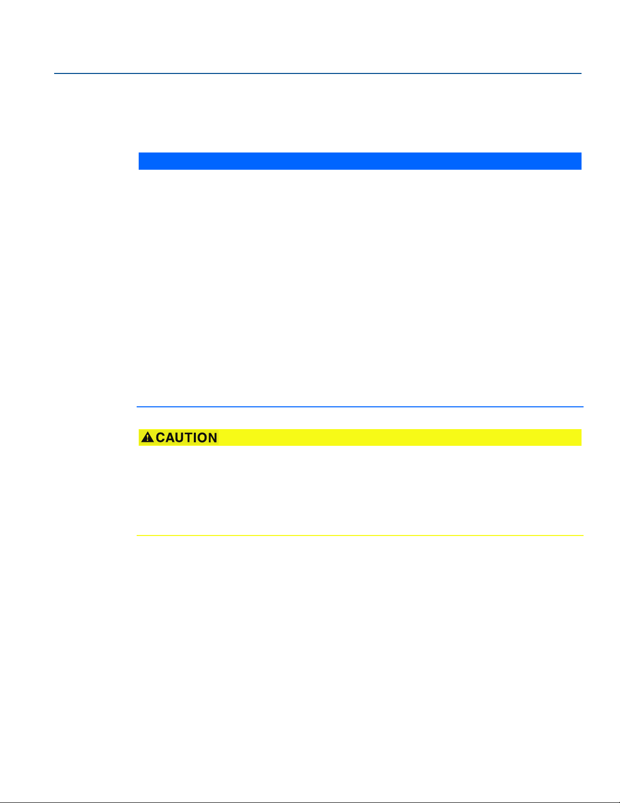
There must be no risk of ‘bridging’ the forks (see Figure 2-2). Examples of media that can create
‘bridging’ of forks are dense paper slurries and bitumen.
Figure 2-2. Avoid Product Build-up
Installation
December 2016
Installation
Application guidelines
Ensure the process is operating within the level switch operating temperature and pressure ranges
(see “Specifications” on page 35).
Ensure the liquid viscosity is within the recommended range (see “Specifications” on page 35).
Check that the liquid density is higher than 37.5 lb/ft
Liquid density affects the switchpoint e.g. dry-to-wet (see Figure 2-3 on page 8).
Check for risk of coating build-up on the forks.
Avoid situations where drying and coating products may create excessive build-up. Problems may
occur if the product coats and then dries, causing caking.
Check the solids content in the liquid.
As a guideline, the maximum solid particle diameter in the liquid is 0.2 in. (5 mm).
Extra consideration is needed when dealing with particles bigger than 0.2 in. (5 mm).
Consult the factory for advice.
In almost all cases, the level switch is insensitive to foams (i.e. does not see the foam).
However in rare occasions, some very dense foams may be seen as liquid; known examples of this are
found in ice-cream and orange juice manufacturing.
3
(600 kg/m3) (see “Specifications” on page 35).
7
Page 14
Installation
SP
HYSP
0.1 in.
(2.5 mm)
0.5 in.
(13 mm)
0.5 in.
(13 mm)
December 2016
Reference Manual
00809-0100-4030, Rev FA
Figure 2-3. Switching Points
SP: Switching point (H20)
HY: Switching Hysteresis
Note
When mounted vertically, a low density media has a switching point closer to the process connection.
A high density media has a switching point closer to fork tip.
2.2.4 Installation considerations
For dimensional drawings, see “Dimensional drawings” on page 39.
Device identification
To identify the Rosemount 2120 Level Switch version, see the labels on the housing and on the
electronics cassette inside the housing. See Appendix B: Product Certifications for approval information.
Allow adequate space outside tank or pipe
Mount the level switch so that it is removable. Clearance of 1.2 in. (30 mm) is required for cover removal.
Ensure there is sufficient room for electrical connections. The glass-filled nylon housing can be rotated to
assist with the cabling, but the metal housings cannot be rotated.
Fit the cover correctly
Ensure the housing O-ring is sitting evenly and then tighten the housing cover to form a good seal.
Always use Emerson O-rings.
8
Installation
Page 15

Reference Manual
00809-0100-4030, Rev FA
Grounding on metal housings
Always ground the housing in accordance with national and local electrical codes.
The most effective grounding method for the metal housing is a direct connection to earth ground with
minimal impedance. Housings with NPT conduit entries do not have an earth ground point and must use
the fork earth.
Do not change the level switch
Do not change the level switch fork in any way (Figure 2-4).
Figure 2-4. Do Not Change the Level Switch Fork
Installation
December 2016
How to handle the level switch
Handle the level switch with great care.
The weight of the level switch with a heavy flange and extended fork length may exceed 37 lb. (18 kg).
A risk assessment is required to be done before carrying, lifting, and installing the level switch.
Use both hands to carry the extended length versions, and do not hold using the forks (Figure 2-5 on
page 10). For hygienic applications, the level switch must be hygienically cleaned before installation and
handled in strict accordance with hygienic standards.
Hygienic installation
See “Hygienic installations” on page 62 for the hygienic approvals and compliance requirements.
These requirements are also in the Rosemount 2120 Quick Start Guide
for other language versions).
(seeEmerson.com/Rosemount
Installation
9
Page 16

Installation
December 2016
Reference Manual
00809-0100-4030, Rev FA
Figure 2-5. Handling the Rosemount 2120
OK OK
2.2.5 Installation recommendations
Test the system by using the magnetic test-point (see “Magnetic test point” on page 28).
Avoid installing near to liquid entering the tank at the fill point.
Avoid heavy splashing on the forks. Increasing the time delay reduces accidental switching.
Allow for a sufficient distance between product build-up and fork (see Figure 2.2.4 on page 8).
Ensure the installation does not create tank crevices around the forks where liquid may collect.
This can happen with high viscosity and high density liquids.
Extra consideration is needed if the plant vibration is close to the 1400 Hz operating frequency
of the level switch.
Supporting the extended fork avoids long fork length vibration
(see Figure 2-6 on page 11 or Figure 2-7 on page 12, depending on installation).
10
Installation
Page 17

Reference Manual
OK
OK
OK
OK
3.28 ft.
(1.0 m)
3.28 ft.
(1.0 m)
Maximum
3.28 ft.
(1.0 m)
3.28 ft.
(1.0 m)
3.28 ft.
(1.0 m)
Maximum
3.28 ft.
(1.0 m)
00809-0100-4030, Rev FA
Figure 2-6. Required Supports for Extended Fork (Standard)
Installation
December 2016
Installation
11
Page 18

Installation
OK
OK
OK
OK
2.3 ft.
(0.7 m)
0.65 ft.
(0.2 m)
Maximum
1.3 ft.
(0.4 m)
0.65 ft.
(0.2 m)
2.3 ft.
(0.7 m)
Maximum
1.3 ft.
(0.4 m)
2.3 ft.
(0.7 m)
2.3 ft.
(0.7 m)
2.3 ft.
(0.7 m)
2.3 ft.
(0.7 m)
December 2016
Reference Manual
00809-0100-4030, Rev FA
Figure 2-7. Required Supports for Extended Forks (Marine GL Approval)
12
Installation
Page 19

Reference Manual
A
B
A
B
B
B
B
A
A
A
A
B
B
A
00809-0100-4030, Rev FA
2.2.6 Installation examples
Figure 2-8. High and Low Level Alarms
A. Dry
B. Wet
Figure 2-9. Pump Control or Overfill Protection
Installation
December 2016
A. Dry
B. Wet
Figure 2-10. Pump or Empty Pipe Protection
A. Dry
B. Wet
Installation
13
Page 20

Installation
A
C
B
D
E
F
December 2016
2.3 Installation procedures
2.3.1 Mechanical
Sealing
Figure 2-11. Sealing
Reference Manual
00809-0100-4030, Rev FA
A. PTFE
B. NPT or BSPT (R) thread
C. Gasket
D. BSPP (G) thread
E. Tri Clamp
F. The Tri Clamp seal is supplied as an as accessory kit (see “Spare parts and accessories” on page 50)
14
Installation
Page 21

Reference Manual
A
B
C
00809-0100-4030, Rev FA
2.3.2 Correct fork alignment
Ensure the fork is correctly aligned by using the notches and grooves as indicated in Figure 2-12.
Figure 2-12. Correct Fork Alignment
Installation
December 2016
A. Alignment groove on standard length Rosemount 2120
B. Alignment notch on flanged Rosemount 2120
C. Alignment notch on extended length Rosemount 2120
Pipe installation
Figure 2-13. Pipe Installation
OK
Note
The glass-filled nylon housing of a Rosemount 2120 can be rotated to assist with cabling, but the metal
housing cannot be rotated.
Installation
15
Page 22

Installation
OKOK
OK
December 2016
Reference Manual
00809-0100-4030, Rev FA
Tank installation
Figure 2-14. Tank Installation
16
OK OK
OK
Note
The glass-filled nylon housing of a Rosemount 2120 can be rotated to assist with cabling, but the metal
housing cannot be rotated.
Installation
Page 23

Reference Manual
OK
A
B
A
00809-0100-4030, Rev FA
2.3.3 Tightening the threaded level switch
Figure 2-15. Tightening the Threaded Rosemount 2120
2.3.4 Insulation
Figure 2-16. Insulation
Installation
December 2016
A. 3.9 in. (100 mm) clearance all around
B. ROCKWOOL
Installation
®
17
Page 24

Installation
OPERATION MODE
Dry On Mode
Dry
Wet
Wet On Mode
Dry
Wet
Dry On Wet On
Seconds Delay
0.3 0.3
3
30
10
1
3
30
10
1
12
3
OUT
+
-
4
PLC/PNP
Isolate Supply
Before Removing
B
A
A
A
December 2016
Reference Manual
00809-0100-4030, Rev FA
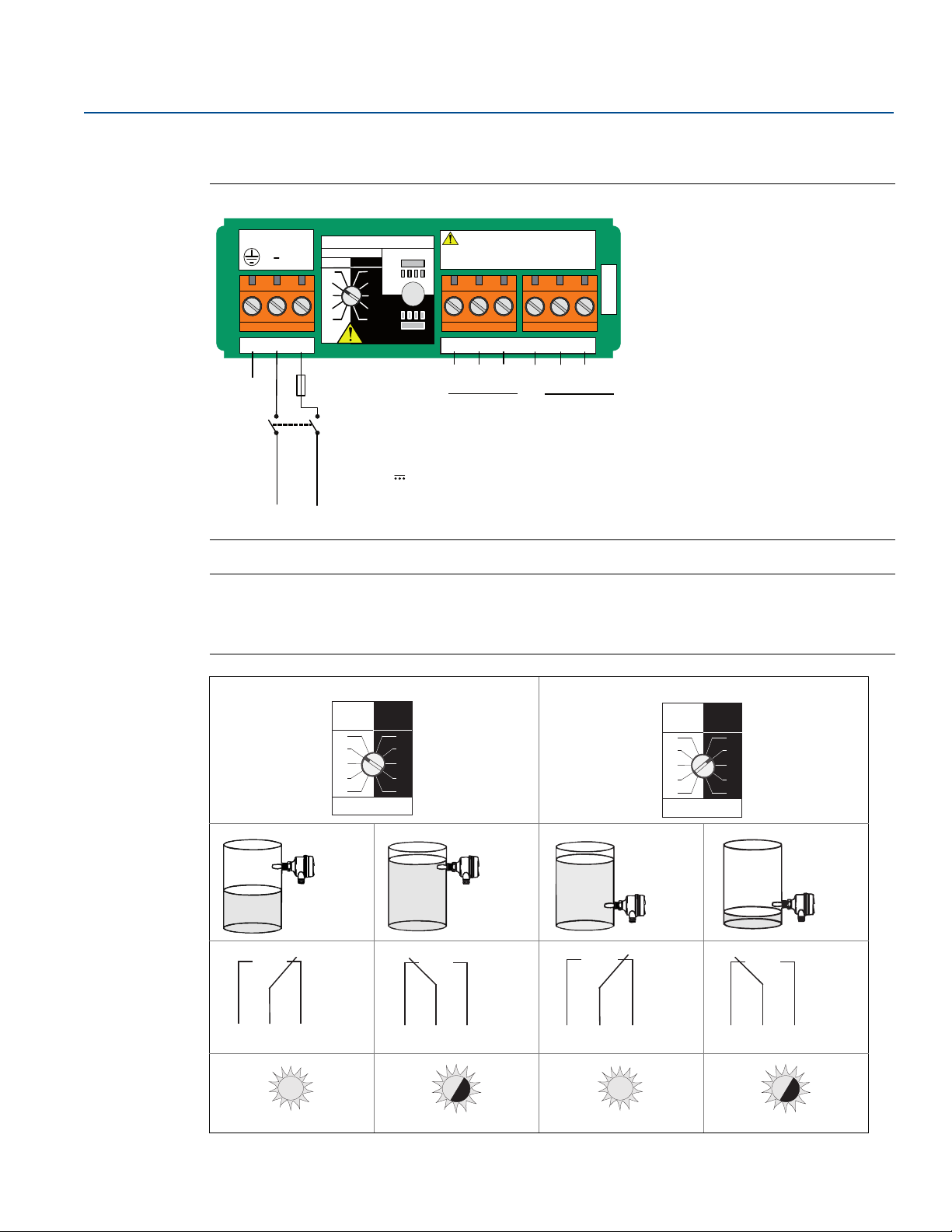
2.4 Setting the mode switch and switching time delay
1. Select “Dry on” or “Wet on” mode.
2. Select 0.3, 1, 3, 10, or 30 seconds for the delay before switching output state.
Note
There is a five second delay when changing mode or time delay. The small cut-out in the rotating switch
indicates time delay and mode.
Recommended installation for high level is “Dry on” (Figure 2-18) and for low level it is “Wet on”
(Figure 2-19). Do not install in the normally ‘off’ state.
Figure 2-17. Top-down View: Example Cassette Inside Housing
A. LED
B. Mode Switch/Time Delay
Figure 2-18. “Dry On” Mode, One Second Time Delay (Typical for High Level Applications)
Dry On Wet On
0.3 0.3
1
3
10
30
1
3
10
30
Seconds Delay
A. Mode “Dry On”
Figure 2-19. “Wet On” Mode, One Second Time Delay (Typical for Low Level Applications)
Dry On Wet On
0.3 0.3
1
3
10
30
Seconds Delay
1
3
10
30
A. Mode “Wet On”
Installation
18
Page 25

Reference Manual
00809-0100-4030, Rev FA
2.5 LED indication
Table 2-1. LED Indication
LED flash rate Switch status
Continuous Output state is on
1 every second Output state is off
1 every 2 seconds Uncalibrated – Refer to “Replacement and calibration of
1 every 4 seconds Load fault; load current too high; load short circuit
Installation
December 2016
electronic cassettes” on page 31
2 times every second Indication of successful calibration
3 times every second Internal PCB fault (microprocessor, ROM, or RAM)
– Refer to “Product recycling and disposal” on page 4
Off Problem (e.g. supply)
Installation
19
Page 26
Installation
December 2016
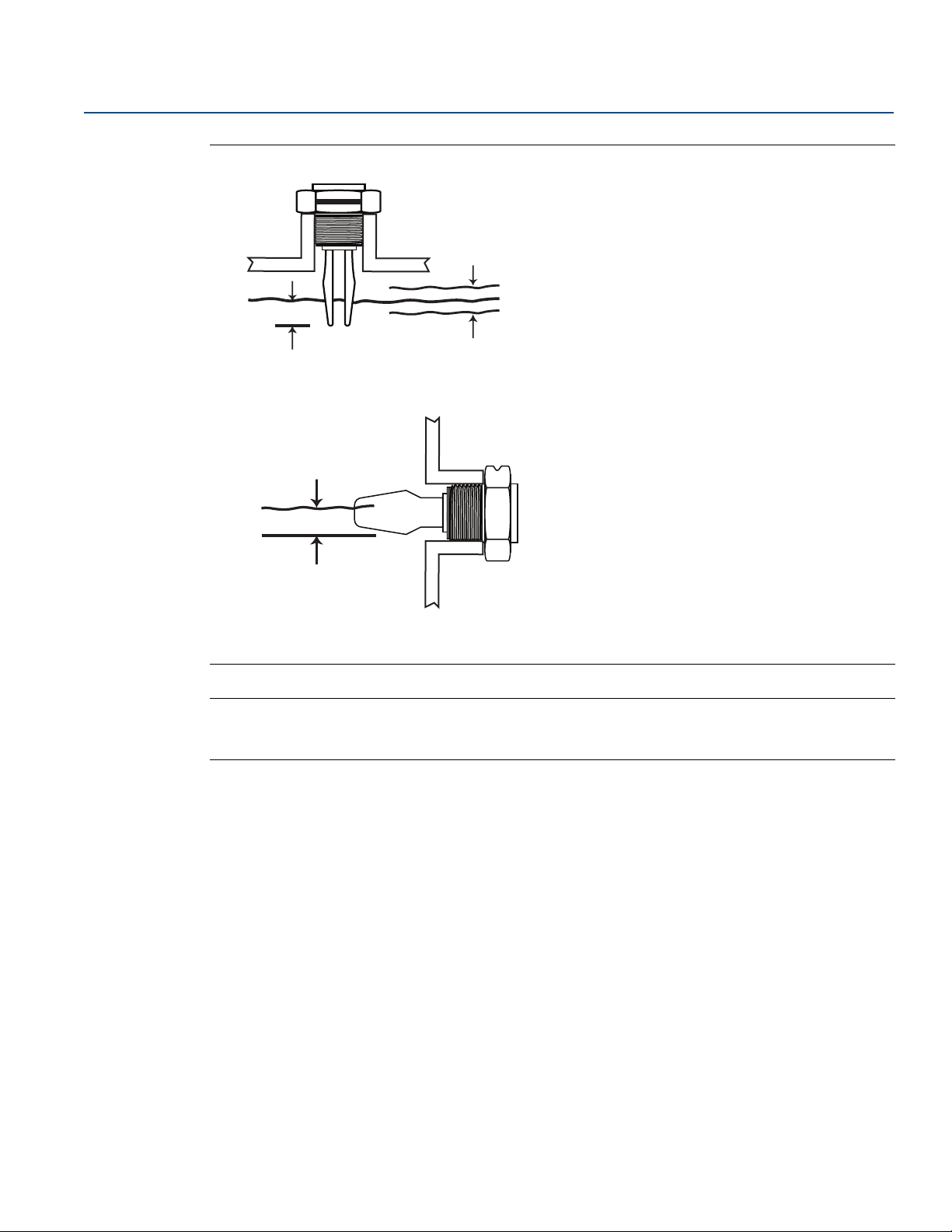
2.6 Electrical installation
Before use, check that suitable cable glands and blanking plugs
are fitted and fully tightened.
Isolate supply before connecting the switch or removing
the electronics.
The Protective Earth (PE) terminal must be connected to an
external earthing system.
Note
When replacing a cassette, it is important to re-calibrate.
Refer to “Replacement and calibration of electronic cassettes” on page 31.
2.6.1 Direct load switching electronics cassette
Figure 2-20. Direct Load Switching (Two-wire, Red Label)
Reference Manual
00809-0100-4030, Rev FA
LOAD
123
PE
(Ground)
Neutral
0V
LINE
R
I
L
Fuse 2A(T)
DPST
Live
+V
OPERATION MODE
Dry On Mode
Dry
Wet
Dry
Wet
Wet On Mode
Dry On Wet On
0.3 0.3
1
3
10
30
Seconds Delay
R = External load (must be fitted)
U = 20 - 264 V ~ (ac) (50/60Hz)
< 4
mA at 20 °C (24 - 230 Vac)
I
OFF
I
< 6
mA at -40 to 80 °C (20 - 264 Vac)
OFF
=
20 - 500
I
L
IPK
U = 20 - 60V (dc))
I
OFF
IL =
IPK
mA
= 5 A, 40 ms (inrush)
< 4 mA
20 - 500 mA
= 5 A, 40 ms (inrush)
Direct Load
Switching
1
WARNING
3
10
Isolate Supply
30
Before Removing
Note
A DPST (Double Pole, Single Throw) on/off switch must be fitted for safe disconnection of the power
supply. Fit the DPST switch as near as possible to the Rosemount 2120. Keep the DPST switch free of
obstructions. Label the DPST switch to indicate it is the supply disconnection device for the
Rosemount 2120.
20
Relay Connection Warning
The Rosemount 2120 requires a minimum current to operate (I
), which continues to flow when the
OFF
output is ‘off’. If selecting a relay to wire in series with the Rosemount 2120, ensure the drop-out voltage
of the relay is greater than the voltage generated across the relay coil when I
flows through it.
OFF
Installation
Page 27

Reference Manual
=Load on
= Load off
Dry On Wet On
Seconds Delay
0.3 0.3
3
30
10
1
3
30
10
1
Dry On Wet On
Seconds Delay
0.3 0.3
30
10
3
30
10
1
3
1
U
N L
0V
+V
Fuse
2A(T)
I
L
12V
DPST
Fuse
2A(T)
N L
0V
+V
I
L
<4mA
DPST
Fuse
2A(T)
N L
0V
+V
I
L
<4mA
DPST
00809-0100-4030, Rev FA
High level, dry = on Low level, wet = on
U
12V
I
L
Fuse
2A(T)
DPST
N L
+V
0V
Installation
December 2016
Installation
LED on continuously
LED flashes every second
LED on continuously
LED flashes every second
21
Page 28

Installation
OUT
-
+
PLC
+
I/P
I
L
<100 A
OUT
-
+
PLC
+
I/P
I
L
<100 A
OUT
-
+
+
I
L
Fuse
1A(T)
R
< 100 A
OUT
-
+
+
U
<3V
I
L
Fuse
1A(T)
R
December 2016
2.6.2 PNP/PLC electronics cassette
Figure 2-21. PNP Output for Load and Direct PLC Switching (Yellow Label)
Reference Manual
00809-0100-4030, Rev FA
12
PE
(Ground)
+
+V
PLC/PNP
Isolate Supply
Before Removing
1
3
10
30
= 0 - 500mA
)
= U - 2.5 Vac (20 °C)
= U - 2.75 Vac (-40 to 80 °C)
< 100A
-
OUT
3
4
Fuse 2A(T)
0VO/P
OPERATION MODE
Dry On Mode
Dry
Wet
Dry
Wet
Wet On Mode
U = 20 - 60 V (dc)
I < 4 mA + I
L
Dry On Wet On
0.3 0.3
1
3
10
30
Seconds Delay
I
L (MAX
IPK
= 5 A, 40 ms (inrush)
U
OUT(ON)
U
OUT(ON)
I
L (OFF)
High level Dry = ON Low level Wet = ON
Dry On Wet On
0.3 0.3
1
3
10
30
Seconds Delay
1
3
10
30
Dry On Wet On
0.3 0.3
1
3
10
30
Seconds Delay
1
3
10
30
OUT
-
+
U
<3V
I
L
I/P
+
= Load off
=Load on
Fuse
1A(T)
PLC
OUT
<3V
-
U
R
I
L
+
+
LED on continuously
22
LED flashes every second
LED on continuously
OUT
-
+
U
<3V
I
L
I/P
+
PLC
OUT
< 100 A
-
R
I
L
Fuse
1A(T)
+
+
LED flashes every second
Installation
Page 29

Reference Manual
NC
C
NO
NC NO
789
NOCNC
RELAY
123
LN
45
6
NOCNC
OPERATION MODE
Dry O n
Dry
Wet
Wet On
Dry
Wet
Dry On
Wet On
Second s D el ay
30
10
3
1
0.3 0.3
30
10
3
1
Isolate Suppl y Before Removing
Warning
C
Resistive Load
cos φ = 1 ;
L/R = 0 ms
ac:
dc:
Inductive Load
Fuse 0.5 (T)PE
(Ground)
DPST
N
0V +V
Live
U = 20...264 V ~ (ac)
(50/60 Hz)
U = 20...60 V (dc)
I < 6 mA
I < 6 mA
I
MAX
= 5 A
U
MAX
= 250 V
P
MAX
= 1250 VA
U
MAX
= 30 V
P
MAX
= 240 W
cos φ = 0.4 ;
L/R = 7 ms
ac:
dc:
I
MAX
= 3.5 A
U
MAX
= 250 V
P
MAX
= 875 VA
U
MAX
= 30 V
P
MAX
= 170 W
Dry On Wet On
Seconds Delay
0.3 0.3
30
10
3
30
10
1
3
1
00809-0100-4030, Rev FA
2.6.3 Relay output electronics cassette (standard version)
Figure 2-22. Relay Output, DPCO (Green Label, Standard Cassette Version)
Installation
December 2016
Installation
Note
A Double Pole, Single Throw on/off switch must be fitted for safe disconnection of the power supply.
Fit the DPST switch as near as possible to the Rosemount 2120 Level Switch. Keep the DPST switch free of
obstructions. Label the DPST switch to indicate it is the supply disconnection device for the level switch.
High level, dry = on Low level, wet = on
Dry On Wet On
0.3 0.3
NC NOC
LED on continuously
1
3
10
30
Seconds Delay
1
3
10
30
NC NOC
LED flashes every second
NC NOC
LED on continuously
NC NOC
LED flashes every second
23
Page 30
Installation
Dry On Wet On
Seconds Delay
0.3 0.3
30
10
3
30
10
1
3
1
December 2016
Reference Manual
00809-0100-4030, Rev FA
2.6.4 Relay output electronics cassette (12 Vdc nominal version)
Figure 2-23. Relay Output, DPCO (Green Label, 12 Vdc Nominal Cassette Version)
Isolate Suppl y Before Removing12 VDC NOM.
NOCNC
45
NC NO
Resistive Load
cos φ = 1 ;
L/R = 0 ms
I
MAX
ac:
U
P
dc:
U
P
C
= 2 A
= 125 V
MAX
= 62.5 VA
MAX
= 30 V
MAX
= 60 W
MAX
6
NOCNC
789
C
NC
NO
Inductive Load
cos φ = 0.4 ;
L/R = 7 ms
I
= 1 A
MAX
ac:
= 125 V
U
MAX
P
= 37.5 VA
MAX
dc:
U
= 30 V
MAX
P
= 30 W
MAX
RELAY
(Ground)
+
123
0V +V
OPERATION MODE
Second s D el ay
Dry On
Wet On
0.3 0.3
1
3
10
30
Fuse 0.5 (T)PE
DPST
U = 9...30 V (dc)
I < 4 mA
Dry O n
Dry
Wet
1
3
10
Dry
30
Wet
Wet On
Note
A Double Pole, Single Throw on/off switch must be fitted for safe disconnection of the power supply. Fit
the DPST switch as near as possible to the Rosemount 2120. Keep the DPST switch free of obstructions.
Label the DPST switch to indicate it is the supply disconnection device for the Rosemount 2120.
NC NOC
LED on continuously
High level, dry = on Low level, wet = on
Dry On Wet On
0.3 0.3
1
3
10
30
Seconds Delay
1
3
10
30
NC NOC
LED flashes every second
NC NOC
LED on continuously
NC NOC
LED flashes every second
24
Installation
Page 31

Reference Manual
OPERATION MODE
Dry On Mode
Dry
Wet
Wet On Mo d e
Dry
Wet
Dry On Wet On
Seconds Delay
0.3 0.3
3
30
10
1
3
30
10
1
12
+-
EN 50227 / NAMUR
ION= 2.2 ... 2.5 mA
I
OFF
= 0.8 ... 1.0 mA
+
-
A certified intrinsically safe
isolat ing am plifier to IEC 60947-5-6
Ex
Ex
8V
dc
Dry On Wet On
Seconds Delay
0.3 0.3
3
30
10
1
3
30
10
1
+
-
>2.2 mA
+
-
<1.0 mA
+
-
>2.2 mA
+
-
<1.0 mA
00809-0100-4030, Rev FA
2.6.5 NAMUR electronics cassette
Figure 2-24. NAMUR (Light Blue Label)
Installation
December 2016
Note
This electronics cassette is suitable for Intrinsically Safe applications and requires a certified isolating
barrier. See “Product Certifications” on page 51 for Intrinsically Safe approvals.
This electronics cassette is also suitable for non-hazardous (safe) area applications. It can only be
interchanged with the 8/16 mA cassette.
Do not exceed 8 Vdc.
High level Dry = ON Low level Wet = ON
Dry On Wet On
0.3 0.3
1
3
10
30
Seconds Delay
1
3
10
30
Installation
LED on continuously
LED flashes every second
LED on continuously
LED flashes every second
25
Page 32

Installation
+
Dry On Wet On
Seconds Delay
0.3 0.3
3
30
10
1
3
30
10
1
+
> 15 mA
+
< 8.5 mA
+
> 15 mA
+
< 8.5 mA
December 2016
2.6.6 8/16 mA electronics cassette
Figure 2-25. 8/16 mA (Dark Blue Label)
OPERATION M ODE
Dry On Wet On
0.3 0.3
1
3
10
30
Seconds Delay
Ex
12
PE
(Ground)
Dry On Mode
Dry
Wet
Wet
Dry
Wet On Mode
3
15 ... 17 mA
ION=
7.5 ... 8.5 mA
I
=
OFF
1
3
10
30
8/16 mA
24 Vdc Nominal
U
=
Reference Manual
00809-0100-4030, Rev FA
-
Ex
-
Drives 4-20 mA Analog Input
+
A certified intrinsically safe barrier
must be used to meet IS requirements
+
Note
This electronics cassette is suitable for Intrinsically Safe applications and requires a certified isolating
barrier. See “Product Certifications” on page 51 for Intrinsically Safe approvals.
electronics cassette is also suitable for non-hazardous (safe) area applications.
This
In this case, U = 11 - 36 V (dc) and it can only be interchanged with a NAMUR cassette.
High level Dry = ON Low level Wet = ON
Dry On Wet On
0.3 0.3
1
3
10
30
Seconds Delay
1
3
10
30
LED on continuously
26
LED flashes every second
LED on continuously
LED flashes every second
Installation
Page 33

Reference Manual
Service and Troubleshooting
00809-0100-4030, Rev FA
Section 3 Service and Troubleshooting
Safety messages . . . . . . . . . . . . . . . . . . . . . . . . . . . . . . . . . . . . . . . . . . . . . . . . . . . . . . . . . . . . . . . . . . page 27
Magnetic test point . . . . . . . . . . . . . . . . . . . . . . . . . . . . . . . . . . . . . . . . . . . . . . . . . . . . . . . . . . . . . . . page 28
Inspection . . . . . . . . . . . . . . . . . . . . . . . . . . . . . . . . . . . . . . . . . . . . . . . . . . . . . . . . . . . . . . . . . . . . . . . page 29
Maintenance . . . . . . . . . . . . . . . . . . . . . . . . . . . . . . . . . . . . . . . . . . . . . . . . . . . . . . . . . . . . . . . . . . . . . page 29
Spare parts . . . . . . . . . . . . . . . . . . . . . . . . . . . . . . . . . . . . . . . . . . . . . . . . . . . . . . . . . . . . . . . . . . . . . . page 30
Troubleshooting . . . . . . . . . . . . . . . . . . . . . . . . . . . . . . . . . . . . . . . . . . . . . . . . . . . . . . . . . . . . . . . . . . page 30
Service support . . . . . . . . . . . . . . . . . . . . . . . . . . . . . . . . . . . . . . . . . . . . . . . . . . . . . . . . . . . . . . . . . . . page 30
Replacement and calibration of electronic cassettes . . . . . . . . . . . . . . . . . . . . . . . . . . . . . . . . . . page 31
3.1 Safety messages
Procedures and instructions in this manual may require special precautions to ensure the safety of the
personnel performing the operations. Information that raises potential safety issues is indicated by a
caution symbol ( ). The external hot surface symbol ( ) is used when a surface is hot and care must be
taken to avoid possible burns. If there is a risk of an electrical shock, the ( ) symbol is used. Refer to the
safety messages listed at the beginning of each section before performing an operation preceded by this
symbol.
December 2016
Failure to follow these installation guidelines could result in death or serious injury.
Make sure only qualified personnel perform the installation.
Use the Rosemount 2120 Level Switch (“level switch”) only as specified in this manual.
Failure to do so may impair the protection provided by the equipment.
The weight of the level switch with a heavy flange and extended fork length may exceed
37 lb. (18 kg). A risk assessment is required to be done before carrying, lifting, and installing the
level switch.
Explosions could result in death or serious injury.
Do not remove the level switch cover in explosive atmospheres when the circuit is alive.
The level switch cover must be fully engaged and locked to meet explosion-proof requirements.
Verify the operating environment of the level switch is consistent with the appropriate hazardous
locations certifications.
Review Appendix B: Product Certifications for special conditions and safety instructions
associated with a hazardous location installation.
Process leaks could result in death or serious injury.
Install and tighten process connection before applying pressure.
Do not attempt to loosen the process connection while the level switch is in service.
Make sure that the level switch is handled carefully. If the process seal is damaged, gas might
escape from the tank.
Service and Troubleshooting
27
Page 34

Service and Troubleshooting
Output off
Output off
Output on
Output on
No magnet
Magnet
Output off
Output off
Output on
Output on
No magnet
Magnet
December 2016
Electrical shock can result in death or serious injury.
If the level switch is installed in a high-voltage environment and a fault or installation error occurs,
high voltage may be present on the sensor leads and terminals.
Use extreme caution when making contact with the leads and terminals.
Make sure the main power to the level switch is off and the lines to any other external power source
are disconnected or not powered while wiring the level switch.
Ensure the wiring is suitable for the electrical current and the insulation is suitable for the voltage,
temperature, and environment.
External surfaces may be hot.
Care must be taken to avoid possible burns. The flange and process seal may also be hot at high
process temperatures. Allow to cool before servicing.
3.2 Magnetic test point
Reference Manual
00809-0100-4030, Rev FA
A magnetic test point is on the side of the housing (Figures 3-1 or 3-2), allowing a functional test of the
Rosemount 2120 Level Switch. By touching a magnet on the target, the output will change state for as
long as the magnet is present.
Figure 3-1. Magnetic Test Point (Glass-filled Nylon Housing)
2120D0AS1NAAA
41001029
DIRECT LOAD SWITCHING
MAGNETIC
TEST
20 - 264Vac
Supply
POINT
~
50 - 60Hz 2VA
20 - 60Vdc 0.5W
Output Rating:
Load 20 - 500mA
MAX WORKING PRESSURE AT 20°C: 0.25 bar
MAX PROCESS TEMPERATURE: 150°C
MADE IN UNITED KINGDOM
*41001029*
www.rosemount.com
2120D0AS1NAAA
41001029
DIRECT LOAD SWITCHING
MAGNETIC
TEST
20 - 264Vac
Supply
POINT
~
50 - 60Hz 2VA
S
20 - 60Vdc 0.5W
Output Rating:
Load 20 - 500mA
N
MAX WORKING PRESSURE AT 20°C: 0.25 bar
MAX PROCESS TEMPERATURE: 150°C
MADE IN UNITED KINGDOM
*41001029*
www.rosemount.com
MAGNETIC
TEST
POINT
S
N
Figure 3-2. Magnetic Test Point (Metal Housing)
TP
TP
S
TP
N
S
N
28
Service and Troubleshooting
Page 35

Reference Manual
OK
00809-0100-4030, Rev FA
3.3 Inspection
Visually examine the Rosemount 2120 Level Switch for damage. If it is damaged, do not use.
Ensure the housing cover, cable glands, and blanking plugs are fitted securely.
Fit blanking a plug where required.
Ensure the LED flash rate is once every second or continually on.
If anything else is demonstrated, see “LED indication” on page 19.
Figure 3-3. Visually Examine Rosemount 2120
Service and Troubleshooting
December 2016
3.4 Maintenance
Figure 3-4. Maintenance
OK
Note
Only use a soft brush for cleaning.
Service and Troubleshooting
29
Page 36

Service and Troubleshooting
December 2016
3.5 Spare parts
See “Spare parts and accessories” on page 50.
3.6 Troubleshooting
If there is a malfunction, see Table 3-1 for information on possible causes.
Table 3-1. Troubleshooting Chart
Fault Symptom/indication Action/solution
• No LED; no power • Check the power supply; (check the load on direct
• LED flashing • See “LED indication” on page 19.
Reference Manual
00809-0100-4030, Rev FA
load switching electronics).
Does not
switch
Incorrect
switching
Faulty
switching
• Fork is damaged • Replace the Rosemount 2120 Level Switch.
• Thick encrustation
on the fork
• 5 second delay when changing
mode/delay
• “Dry = On” or “Wet = On”
set incorrectly
• Turbulence • Set a longer switching time delay.
• Excessive electrical noise • Suppress the cause of the interference.
• Cassette has been fitted from
another Rosemount 2120 Level
Switch
3.7 Service support
To expedite the return process outside of the United States, contact the nearest Emerson representative.
Within the United States, call the Emerson Instrument and Valves Response Center using the
1 800 654 7768 toll-free number. This center, available 24 hours a day, will assist you with any needed
information or materials.
• Clean the fork with care.
• This is normal – wait 5 seconds.
• Set the correct mode on the electronics cassette.
• Fit the factory supplied cassette and then calibrate.
(See “Replacement and calibration of electronic
cassettes” on page 31)
30
The center will ask for product model and serial numbers, and will provide a Return Material
Authorization (RMA) number. The center will also ask for the process material to which the product was
last exposed.
Individuals who handle products exposed to a hazardous substance can avoid injury if they are
informed of, and understand, the hazard. If the product being returned was exposed to a hazardous
substance as defined by OSHA, a copy of the required Material Safety Data Sheet (MSDS) for each
hazardous substance identified must be included with the returned goods.
Service and Troubleshooting
Page 37

Reference Manual
OPERATION MODE
Dry On Mode
Dry
Wet
Wet On Mode
Dry
Wet
Dry On Wet On
Seconds Delay
0.3 0.3
3
30
10
1
3
30
10
1
12
3
OUT
+
-
4
PLC/PNP
Isolate Supply
Before Removing
00809-0100-4030, Rev FA
Service and Troubleshooting
December 2016
3.8 Replacement and calibration of electronic cassettes
When replacing a damaged or faulty electronic cassette, calibrate the replacement cassette to the
operating frequency of the fork assembly.
This section describes what is required for calibration. Calibration sequence steps 3 to 13 are time
dependent and must be carried out within the noted times. The purpose of the time dependency and
switching sequence is to prevent an accidental calibration from occurring.
If this replacement is taking place in a hazardous area, only qualified personnel should perform the
replacement. All work in hazardous areas must be carried out in accordance with the local code. For
general hazardous area requirements of this equipment, refer to Appendix B: Product Certifications.
Calibration of the device is complex and it may take several attempts before calibration is successful.
3.8.1 Replacement sequence
On Intrinsically Safe (I.S.) approved versions of the Rosemount 2120 Level Switch, it is recommended
that replacement and calibration be performed in a non-hazardous (safe) area.
Note
Intrinsically Safe approved cassettes can only be replaced with the same type of IS cassette.
Non-I.S. cassette types can be interchanged with other non-I.S. cassettes, but a new label must be fitted
and the original part number transferred to the new label. Before starting the replacement and
calibration procedure, ensure that any controlled process will not be adversely affected.
To replace the cassette
1. Isolate and disconnect the power to the Rosemount 2120 Level Switch, and insulate the ends of the
wires. On units with a relay cassette, there may be more than one power source.
2. Remove the cover and disconnect the wires, noting any connections (Figure 3-5) and the exact mode
switch position (Figure 3-6 on page 32) on the cassette to be replaced.
3. Remove and retain the two fixing screws from the base of the cassette and unplug the cassette.
4. Plug in the replacement cassette, replace the screws, reconnect the wires, and set the mode switch to
“Wet On” with a one second delay (Figure 3-7 on page 32).
5. Reconnect the power to the unit.
Figure 3-5. Example of Installed Cassette
Service and Troubleshooting
31
Page 38

Service and Troubleshooting
Dry On Wet On
Seconds Delay
0.3 0.3
3
30
10
1
3
30
10
1
December 2016
Figure 3-6. Mode Switch Setting (Existing Cassette)
Figure 3-7. Mode Switch Setting (Replacement Cassette)
Reference Manual
00809-0100-4030, Rev FA
This is an example of how the existing cassette may look. Here, the mode switch is set to
“Dry On” with a one second delay.
Take note of the actual setting.
SETTING IS: ____________________________________
Dry On Wet On
0.3 0.3
1
3
10
30
Seconds Delay
Set the mode switch of the new cassette to “Wet On” with a one second delay.
1
3
10
30
3.8.2 Calibration sequence
To calibrate the cassette
1. Ensure that the forks are dry, and the mode switch is set to “Wet On” with the
time delay set to 1 second (Figure 3-7).
2. Check that the LED is flashing at a rate of one flash per second.
Proceed to step 8 if it is on continuously.
3. Apply a magnet to the test-point (as shown on page 28).
4. After a one second delay, the LED will be lit continuously.
5. Within once second, rotate the mode switch two steps clockwise.
6. After a two second delay, the LED will go out.
7. Within three seconds, rotate the mode switch two steps counter-clockwise.
Proceed to step 13.
8. Apply a magnet to the test-point (as shown on page 28).
9. After a one second delay, the LED will flash at a rate of one flash per second.
10.Within one second, rotate the mode switch two steps clockwise.
11.After a two second delay, the LED will go out (stop flashing).
12.Within three seconds, rotate the mode switch two steps counter-clockwise.
13.After a two second delay, the LED should flash twice per second.
14.If the LED is flashing twice per second, the calibration has occurred correctly.
Remove the magnet from the test point. After a one second delay, the unit will return to normal
operation. Proceed to step 17.
32
Service and Troubleshooting
Page 39

Reference Manual
00809-0100-4030, Rev FA
15.If the LED is flashing once per second or it is on continuously, the calibration has failed. Remove the
magnet from the test-point, wait ten seconds, and repeat from step 2.
16.If the LED stays off after the two second delay of step 13, the sensor is not working correctly.
Check that the forks are clean and dry. Also, verify there is nothing jamming or touching the sensor.
If no fault is found with the sensor, the entire unit should be returned for repair
(see “Product recycling and disposal” on page 4).
17.Set the mode switch to the original setting noted in Figure 3-6 and wait five seconds.
18.Replace the cover and check that the system works.
Service and Troubleshooting
December 2016
Service and Troubleshooting
33
Page 40

Service and Troubleshooting
December 2016
Reference Manual
00809-0100-4030, Rev FA
34
Service and Troubleshooting
Page 41

Reference Manual
00809-0100-4030, Rev FA
Specifications and Reference Data
December 2016
Appendix A Specifications and Reference Data
Specifications . . . . . . . . . . . . . . . . . . . . . . . . . . . . . . . . . . . . . . . . . . . . . . . . . . . . . . . . . . . . . . . . . . . . page 35
Dimensional drawings . . . . . . . . . . . . . . . . . . . . . . . . . . . . . . . . . . . . . . . . . . . . . . . . . . . . . . . . . . . . . page 39
Ordering information . . . . . . . . . . . . . . . . . . . . . . . . . . . . . . . . . . . . . . . . . . . . . . . . . . . . . . . . . . . . . page 46
A.1 Specifications
A.1.1 General
Product
Rosemount 2120 Level Switch
Measuring principle
Vibrating fork technology
Applications
Most liquids including coating liquids, aerated liquids, and slurries.
A.1.2 Mechanical
Housing / Enclosure
Table A-1. Housing/Enclosure Specifications
Housing code A D X Y S T
Housing material
Rotational Yes No No
Housing paint
LED window Nylon PA12 None None
Conduit entry M20
Ingress
protection
Nylon PA66
30%GF
Not
applicable
IP66/67 to
EN60529
Connections
Threaded, Tri Clamp, and flanged process connections.
See “Process connection size / type” on page 46 for a full list.
Extended lengths
Table A-2. Minimum Extended Lengths
Process connection Minimum extended length
3
/4–in. threaded 3.8 in. (95 mm)
1–in. threaded 3.7 in. (94 mm)
Flanged 3.5 in. (89 mm)
Tri Clamp 4.1 in. (105 mm)
1
/2-in.
ANPT
Al alloy ASTM
B85 A360.0
Polyurethane
paint
3
M20
/4-in.
ANPT
IP66/67 to
EN60529,
®
NEMA
4X
316C12 SST
Not
applicable
3
/4-in.
M20
ANPT
IP66/67 to
EN60529,
NEMA 4X
The maximum extended length is 157.5 in. (4000 mm) except for
ECTFE copolymer coating and mechanically-polished process
connection options which have a maximum length of 59.1 in.
(1500 mm) and 39.4 in. (1000 mm) respectively.
Material selection
Emerson provides a variety of Rosemount product with various
product options and configurations including materials of
construction that can be expected to perform well in a wide range
of applications. The Rosemount product information presented is
intended as a guide for the purchaser to make an appropriate
selection for the application. It is the purchaser’s sole
responsibility to make a careful analysis of all process parameters
(such as all chemical components, temperature, pressure, flow
rate, abrasives, contaminants, etc.), when specifying product,
materials, options and components for the particular application.
Emerson is not in a position to evaluate or guarantee the
compatibility of the process fluid or other process parameters with
the product, options, configuration or materials of construction
selected.
Process connection materials
316/316L stainless steel (1.4401/1.4404 dual certified).
Alloy C (UNS N10002) and Alloy C-276 (UNS N10276)
– available for flanged, and BSPT and NPT threaded process
3
connections (
/4- and 1-in. BSPT (R), and 3/4- and 1-in. NPT).
ECTFE co-polymer coated 316/316L Stainless Steel
(1.4401/1.4404 dual certified) – only available for a flanged
Rosemount 2120 but excludes 1-in./DN25/25A flanges.
3
Gasket material for
/4- and 1-in. BSPP (G) is non-asbestos BS7531
Grade X carbon fiber with rubber binder.
A.1.3 Functional
Maximum operating altitude
6562 ft. (2000 m)
Maximum operating pressure
The final rating depends on the selected process connection.
Threaded connection: see Figure A-1 on page 36 for operating
pressures
Specifications and Reference Data
35
Page 42

Reference Manual
1450 (100)
1160 (80)
-14.5 (-1.0)
-40
(-40)
122
(50)
302
(150)
Process
Temperature °F (°C)
Process Pressure psig (barg)
0 (0)
32
(0)
176 (80)
140
(60)
-40 (-40)
-40
(-40)
302
(150)
Process Temperature °F (°C)
Ambient Temperature °F (°C)
122 (50)
32 (0)
32
(0)
00809-0100-4030, Rev FA
Specifications and Reference Data
December 2016
Clamp glands 02120-2000-0001 and 02120-2000-0002
(page 46) limit the maximum pressure to 18.85 psig (1.3 bar g).
Tri Clamp connection: 435 psig (30 bar g).
Flanged connection:
See Figure A-1 or Table A-3 (whichever gives the lowest
pressure).
Figure A-1. Process Pressure
Table A-3. Maximum Flange Pressure Rating
Standard Class/Rating SST flanges
ASME B16.5 Class 150 275 psig
ASME B16.5 Class 300 720 psig
ASME B16.5 Class 600 1440 psig
EN1092-1 PN 10/16 16 barg
EN1092-1 PN 25/40 40 barg
EN1092-1 PN 63 63 barg
EN1092-1 PN 100 100 barg
JIS B2220 10K 14 barg
JIS B2220 20K 34 barg
1. At 100 °F (38 °C), the rating decreases with an increasing process
temperature.
2. At 122 °F (50 °C), the rating decreases with an increasing process
temperature.
3. At 248 °F (120 °C), the rating decreases with an increasing process
temperature.
Minimum and maximum operating temperatures
See Figure A-2 for operating temperatures.
Clamp glands 02120-2000-0001 and 02120-2000-0002 (page 46)
limit the maximum temperature to 257 °F (125 °C).
(1)
(1)
(1)
(2)
(2)
(2)
(2)
(3)
(3)
Figure A-2. Operating Temperatures
Liquid density requirement
Minimum of 37.5 lb/ft
Liquid viscosity range
Up to 10000 cP (centiPoise).
Solids content and coating
Maximum recommended diameter of solid particles in the liquid is
0.2 in. (5 mm).
For a coating product, avoid bridging of forks.
Switching delay
User selectable 0.3, 1, 3, 10, 30 seconds delay for dry-to-wet and
wet-to-dry switching.
Clean-In-Place (CIP) cleaning
Withstands cleaning routines up to 160 °F (71 °C).
Steam-In-Place (SIP) cleaning
Withstands cleaning routines up to 275 °F (135 °C).
NACE
NACE compliance to MR0175 / ISO 15156 or MR0103, depending
on the option code selected for the model number.
Safety integrity level
The Rosemount 2120 FMEDA is certified for SIL2, and is SIL3
capable, for all electronics except the Direct Load option.
Visit the Rosemount 2120 web page
3
(600 kg/m3).
for additional information.
The ambient temperature for a 8/16 mA cassette is limited to
158 °F (70 °C) in dust applications.
36
Specifications and Reference Data
Page 43

Specifications and Reference Data
December 2016
Reference Manual
00809-0100-4030, Rev FA
A.1.4 Performance
Hysteresis (water)
±0.039-in. (±1 mm) nominal.
Switching point (water)
0.5 in. (13 mm) from tip (vertical) / from edge (horizontal) of fork
(this will vary with different liquid densities).
A.1.5 Electrical
Switching mode
User selectable switching mode (“Dry = on” or “Wet = on”).
Protection
Polarity insensitive
– on Relay (except 12 Vdc version) and Direct Load electronics
Over-current protection
– on Direct Load and PNP/PLC electronics
Short-circuit protection
– on Direct Load and PNP/PLC electronics
Load-missing protection
– on Direct Load and PNP/PLC electronics
Surge protection (to IEC61326)
– available on all versions of the Rosemount 2120
Heartbeat LED
The Rosemount 2120 has a status-indicating ‘heartbeat’ LED,
which can be seen at all times and from all angles through a lens in
the cover (no lens in metal housings).
Grounding
The Rosemount 2120 must always be grounded either through the
terminals or using the external ground connection provided.
Conduit plugs/cable gland
Metal housing:
Conduit entries for explosion-proof areas are shipped with one Exd
plug (loose in bag) and two dust caps fitted. Use suitably rated
cable glands. Unused conduit entries must be sealed with a
suitably rated blanking plug.
Glass-filled nylon housing with direct load, PNP/PLC and IS
(1)
electronics are shipped with one PA66
cable gland and one
blanking plug.
Glass-filled nylon housing with relay electronics are shipped with
two PA66
(1)
cable glands.
Electrical connections
Direct load switching (mains two wire) cassette
LOAD
123
PE
(Ground)
Neutral
0V
LINE
R
I
L
Fuse 2A(T)
DPST
Live
+V
OPERATION MODE
Dry On Mode
Wet On Mode
Dry On WetOn
Dry
Wet
0.3 0.3
1
3
10
Dry
Wet
30
Seconds Delay
R = External load (must be fitted)
U = 20 - 264 V ~ (ac) (50/60Hz)
< 4
mA
I
OFF
=
20 - 500
I
I
U = 20 - 60 V (dc))
I
IL =
I
mA
L
PK
= 5 A, 40 ms (inrush)
< 4 mA
OFF
20 - 500 mA
PK
= 5 A, 40 ms (inrush)
Direct Load
Switching
1
WARNING
3
10
Isolate Supply
30
Before Removing
The LED flashes when the output is ‘off’ and is constantly lit when it
is ‘on’. The LED gives a constant indication that the Rosemount
2120 is functioning correctly (different flash rates are used to
indicate a product malfunction) and gives a local indication of the
process state.
Magnetic test point
A magnetic test point is located on the side of the housing,
allowing a functional test of the Rosemount 2120 and a system
connected to it. By holding a magnet to the target, the output
changes state for as long as the magnet is held there.
Terminal connection (wire diameter)
Minimum 26 AWG, Maximum 14 AWG (0.13 to 2.5 mm2).
Note national regulations.
Specifications and Reference Data
NAMUR (light blue) cassette
OPERATION MODE
Dry On Wet On
Dry
Wet
0.3 0.3
1
3
10
Dry
Wet
30
Seconds Delay
Ex
Ex
+-
8V
dc
12
-
Dry On Mode
Wet On Mo d e
ION= 2.2 ... 2.5 mA
I
= 0.8 ... 1.0 mA
OFF
I
< 1.0 mA
FAULT
+
A certified intrinsically safe
isolating amplifier to IEC 60947-5-6
1. Cable diameter 0.2 to 0.3 in. (5 to 8 mm)
EN 50227 / NAMUR
1
3
10
30
37
Page 44

Reference Manual
+
NC
C
NO
NC NO
789
NOCNC
RELAY
123
LN
45
6
NOCNC
OPERATION MODE
Dry On
Dry
Wet
Wet On
Dry
Wet
Dry On
Wet On
Seconds D el ay
30
10
3
1
0.3 0.3
30
10
3
1
Isolate Supply Before Removing
Warning
C
Resistive Load
cos φ = 1 ;
L/R = 0 ms
ac
dc
Inductive Load
Fuse 0.5 (T)PE
(Ground)
DPST
N
0V +V
Live
U = 20...264 V ~ (ac)
(50/60 Hz)
U = 20...60 V (dc)
I < 6 mA
I < 6 mA
I
MAX
= 5 A
U
MAX
= 250 V
P
MAX
= 1250 VA
U
MAX
= 30 V
P
MAX
= 240 W
cos φ = 0.4 ;
L/R = 7 ms
ac
dc
I
MAX
= 3.5 A
U
MAX
= 250 V
P
MAX
= 875 VA
U
MAX
= 30 V
P
MAX
= 170 W
OPERATION MODE
Dry On Mode
Dry
Wet
Wet On Mode
Dry
Wet
Dry On Wet On
Seconds Delay
0.3 0.3
3
30
10
1
3
30
10
1
12
3
OUT
+
-
4
PLC/PNP
Isolate Supply
Before Removing
PE
(Ground)
0VO/P
U = 20 - 60 V (dc)
I < 4 mA + I
L
I
L (MAX)
= 0 - 500mA
U
OUT(ON)
= U -
2.5 V
I
L (OFF)
< 100A
+V
Fuse 2A(T)
= 5 A, 40 ms (inrush)
IPK
00809-0100-4030, Rev FA
Specifications and Reference Data
December 2016
8/16 mA (dark blue) cassette
OPERATION MODE
Dry
Wet
Wet
Dry
15 ... 17 mA
7.5 ... 8.5 mA
< 3.7 mA
Dry O n WetOn
0.3 0.3
1
3
10
30
Seconds Delay
1
3
10
30
Ex
Ex
3
12
I
ON
I
PE
(Ground)
-
-
Drives 4-20 mA Analog Input
OFF
I
FAULT
+
+
Dry On Mode
Wet On Mode
=
=
A certified intrinsically safe barrier
must be used to meet IS requirements
DPCO dual relay cassette (standard version)
U
=
8/16 mA
24 Vdc Nominal
DPCO dual relay cassette (12 Vdc nominal version)
Dry On
Wet On
Isolate Supply Before Removing12 VDC NOM.
NOCNC
45
C
NC NO
Resistive Load
cos φ = 1 ;
L/R = 0 ms
= 2 A
I
MAX
ac:
= 125 V
U
MAX
P
= 62.5 VA
MAX
dc:
U
= 30 V
MAX
P
= 60 W
MAX
6
789
C
NC
Inductive Load
cos φ = 0.4 ;
L/R = 7 ms
I
MAX
ac:
= 125 V
U
MAX
P
= 37.5 VA
MAX
dc:
U
= 30 V
MAX
P
= 30 W
MAX
(Ground)
+
123
0V +V
OPERATION MODE
Seconds D el ay
Dry On
0.3 0.3
1
3
10
30
Fuse 0.5 (T)PE
DPST
U = 9...30 V (dc)
I < 4 mA
Wet On
Dry
Wet
1
3
10
Dry
30
Wet
Solid state PNP output for direct interface to a PLC
NOCNC
RELAY
NO
= 1 A
Note
The external DPST switch that is shown in the wiring diagrams is an optional local disconnect (customer supplied).
38
Specifications and Reference Data
Page 45

Specifications and Reference Data
0.5 (13)
switchpoint (when
mounted horizontally)
0.5 (13) switchpoint
(when mounted vertically)
5
(127)
3.5 (89)
1.7
(44)
A
2.7
(69
Allow 1.2 (30)
to remove cover
Glass-filled nylon housing
Aluminum/stainless steel housing
Allow 1.2 (30)
to remove cover
4.7 (120)
5.9
(151)
2.7
(69)
1.7
(44)
0.5 (13) switchpoint
(when mounted vertically)
0.5 (13)
switchpoint (when
mounted horizontally)
B
C
D
C
D
4 (102)
December 2016
A.2 Dimensional drawings
Figure A-3. 3/4- and 1-in. Threaded Mounting (Standard Length)
Reference Manual
00809-0100-4030, Rev FA
A. Cable entry M20 x 1.5 or 1/2-in. ANPT C. 1.6 (40) A/F hexagon
B. Cable entry M20 x 1.5 or
Dimensions are in inches (millimeters). See the Rosemount 2120 web page
3
/4-in. ANPT D. 3/4- or 1-in. thread
for all 1-in. BSPP threaded dimensional drawings.
Specifications and Reference Data
39
Page 46

Reference Manual
D
E(M)
1.7
(44)
0.5 (13)
switchpoint (when
mounted horizontally)
0.5 (13) switchpoint
(when mounted vertically)
5.9
(151)
Allow 1.2 (30)
to remove cover
Ø1.1 (28) for 1-in. thread
Ø0.9 (23) for
3
/4-in. thread
4.7 (120)
B
Allow 1.2 (30)
to remove cover
6.7
(171)
C
D
Ø1.1 (28) for 1-in. thread
Ø0.9 (23) for
3
/4-in. thread
0.5 (13) switchpoint
(when mounted vertically)
0.5 (13)
switchpoint (when
mounted horizontally)
1.7
(44)
E(M)
C
A
3.5 (90)
4 (102)
Glass-filled nylon housing
Aluminum/stainless steel housing
00809-0100-4030, Rev FA
Figure A-4. 3/4- and 1-in. Thread Mounting (Extended Length)
Specifications and Reference Data
December 2016
A. Cable entry M20 x 1.5 or 1/2-in. ANPT C. 1.6 (40) A/F hexagon
B. Cable entry M20 x 1.5 or
Dimensions are in inches (millimeters). See the Rosemount 2120 web page
Table A-4. Fork Length for 3/4- and 1-in. Threaded Rosemount 2120
3
/4-in. ANPT D. 3/4- or 1-in. thread
Process
connection
3
/4-in. thread 1.7 in. (44 mm) 3.75 in. (95 mm) 157.5 in. (4000 mm)
Standard length
fork length code A
1-in. thread 1.7 in. (44 mm) 3.74 in. (94 mm) 157.5 in. (4000 mm)
for all 1-in. BSPP threaded dimensional drawings.
Minimum length
fork length code E (M)
Maximum length
fork length code E (M)
40
Specifications and Reference Data
Page 47

Specifications and Reference Data
0.5 (13) switchpoint
(when mounted horizontally)
0.5 (13) switchpoint
(when mounted vertically)
5.2
(132)
3.5 (90)
1.7
(44)
A
2.5
(64)
Allow 1.2 (30)
to remove cover
Glass-filled nylon housing
(and not hygienically approved)
Aluminum/stainless steel housing
(and not hygienically approved)
Allow 1.2 (30)
to remove cover
4.7 (120)
6.1
(155)
2.5
(64)
1.7
(44)
0.5 (13) switchpoint
(when mounted vertically)
0.5 (13) switchpoint
(when mounted horizontally)
B
C
C
D
4 (102)
D
Ø0.9 (23)
Ø0.9 (23)
0.5 (13) switchpoint
(when mounted horizontally)
0.5 (13) switchpoint
(when mounted vertically)
5.2
(132)
3.5 (90)
1.7
(44)
A
2.5
(64)
Allow 1.2 (30)
to remove lid
Ø1.65 (42)
D
4 (102)
Glass-filled nylon housing
(and hygienically approved)
Aluminum steel housing
(and hygienically approved)
Allow 1.2 (30)
to remove lid
4.7 (120)
6.1
(155)
2.5
(64)
1.7
(44)
0.5 (13) switchpoint
(when mounted vertically)
0.5 (13) switchpoint
(when mounted horizontally)
B
D
Ø1.65 (42)
Ø0.9 (23)
Ø0.9 (23)
December 2016
Figure A-5. Tri Clamp Mounting (Standard Length, Surface Finish Codes 1 and 2)
Reference Manual
00809-0100-4030, Rev FA
A. Cable entry M20 x 1.5 or 1/2-in. ANPT C. 1.6 (40) A/F hexagon
B. Cable entry M20 x 1.5 or
Dimensions are in inches (millimeters).
Figure A-6. Tri Clamp Mounting (Standard Length, Surface Finish Codes 3, 4, 7, and 8)
3
/4-in. ANPT D. 11/2-in. (38 mm) or 2-in. (51 mm) Tri Clamp, surface finish codes 1 and 2
A. Cable entry M20 x 1.5 or 1/2-in. ANPT C. 1.6 (40) A/F hexagon
B. Cable entry M20 x 1.5 or
Dimensions are in inches (millimeters).
Specifications and Reference Data
3
/4-in. ANPT D. 11/2-in. (38 mm) or 2-in. (51 mm) Tri Clamp, surface finish codes 3, 4, 7, and 8
41
Page 48

Reference Manual
E(M)
1.7
(44)
0.5 (13) switchpoint
(when mounted horizontally)
0.5 (13) switchpoint
(when mounted vertically)
5.2
(132)
Allow 1.2 (30)
to remove cover
Ø1.1 (28)
4.7 (120)
B
Allow 1.2 (30)
to remove cover
6.4
(162)
C
Ø1.1 (28)
0.5 (13) switchpoint
(when mounted vertically)
0.5 (13) switchpoint
(when mounted horizontally)
1.7
(44)
E(M)
C
A
3.5 (90)
4 (102)
Glass-filled nylon housing
(and not hygienically approved)
Aluminum/stainless steel housing
(and not hygienically approved)
Ø1.6 (41)
Ø1.6 (41)
Specifications and Reference Data
00809-0100-4030, Rev FA
Figure A-7. Tri Clamp Mounting (Extended Length, Surface Finish Codes 1 and 2)
December 2016
A. Cable entry M20 x 1.5 or 1/2-in. ANPT C. 11/2-in. (38 mm) or 2-in. (51 mm) Tri Clamp, surface finish codes 1 and 2
B. Cable entry M20 x 1.5 or
Dimensions are in inches (millimeters).
Table A-5. Fork Length for Tri Clamp Rosemount 2120 (Not Hygienically Approved)
Process
connection
Tri Clamp
(surface finish code 1)
Tri Clamp
(surface finish code 2)
42
3
/4-in. ANPT
fork length code A
Standard length
fork length code E (M)
1.7 in. (44 mm) 4.13 in. (105 mm) 157.5 in. (4000 mm)
Minimum length
Maximum length
fork length code E (M)
1.7 in. (44 mm) 4.13 in. (105 mm) 157.5 in. (1000 mm)
Specifications and Reference Data
Page 49

Specifications and Reference Data
E(M)
1.7
(44)
0.5 (13) switchpoint
(when mounted horizontally)
0.5 (13) switchpoint
(when mounted vertically)
5.2
(132)
Allow 1.2 (30)
to remove cover
Ø0.9 (23)
4.7 (120)
B
Allow 1.2 (30)
to remove cover
6.1
(155)
C
Ø0.9 (23)
0.5 (13) switchpoint
(when mounted vertically)
0.5 (13) switchpoint
(when mounted horizontally)
1.7
(44)
E(M)
C
A
3.5 (90)
4 (102)
Glass-filled nylon housing
(and hygienically approved)
Aluminum housing
(and hygienically approved)
Ø1.65 (42)
Ø1.65 (42)
December 2016
Figure A-8. Tri Clamp Mounting (Extended Length, Surface Finish Codes 3, 4, 7, and 8)
Reference Manual
00809-0100-4030, Rev FA
A. Cable entry M20 x 1.5 or 1/2-in. ANPT C. 11/2-in. (38 mm) or 2-in. (51 mm) Tri Clamp, surface finish codes 3, 4, 7, and 8
B. Cable entry M20 x 1.5 or
Dimensions are in inches (millimeters).
Table A-6. Fork Length for Tri Clamp Rosemount 2120 (Hygienically Approved)
(surface finish codes 3, 4, 7, and 8)
Specifications and Reference Data
Process
connection
Tri Clamp
3
/4-in. ANPT
Standard length
fork length code A
1.7 in. (44 mm) 4.13 in. (105 mm) 157.5 in. (1000 mm)
Minimum length
fork length code E (M)
Maximum length
fork length code E (M)
43
Page 50

Reference Manual
4.8
(121)
1.7
(44)
0.5 (13)
Switchpoint (when
mounted horizontally)
Ø1.1 (28) for 1
1
/2 in. or larger flange
Ø0.9 (23) for up to 1 in. flange
0.5 (13)
Switchpoint (when
mounted vertically)
Allow 1.2 (30)
to remove cover
4.7 (120)
B
Allow 1.2 (30)
to remove cover
6
(154)
4.0
(102)
1.7
(44)
0.5 (13)
Switchpoint (when
mounted horizontally)
0.5 (13)
Switchpoint (when
mounted vertically)
Ø1.1 (28) for 1
1
/2 in. or
larger flange;
Ø0.9 (23) for up to 1 in. flange
A
3.5 (90)
4 (102)
4
(102)
Glass-filled nylon housing
Aluminum/stainless steel housing
00809-0100-4030, Rev FA
Figure A-9. Flange Mounting (Standard Length)
Specifications and Reference Data
December 2016
A. Cable entry M20 x 1.5 or 1/2-in. ANPT
B. Cable entry M20 x 1.5 or
Dimensions are in inches (millimeters).
44
3
/4-in. ANPT
Specifications and Reference Data
Page 51

Specifications and Reference Data
1.7
(44)
4.8
(121)
E(M)
0.5 (13)
Switchpoint (when
mounted horizontally)
Ø1.1 (28) for 1
1
/2 in. or
larger flange;
Ø0.9 (23) for up to 1 in. flange
0.5 (13)
Switchpoint (when
mounted vertically)
Allow 1.2 (30)
to remove cover
4.7 (120)
Allow 1.2 (30) to
remove cover
0.5 (13)
Switchpoint (when
mounted horizontally)
0.5 (13)
Switchpoint (when
mounted vertically)
Ø1.1 (28) for 1
1
/2 in. or
larger flange;
Ø0.9 (23) for up to 1 in. flange
6
(154)
E(M)
3.5 (89)
4 (102)
B
A
1.7
(44)
Glass-filled nylon housing
Aluminum/stainless steel housing
December 2016
Figure A-10. Flange Mounting (Extended Length)
Reference Manual
00809-0100-4030, Rev FA
A. Cable entry M20 x 1.5 or 1/2-in. ANPT
B. Cable entry M20 x 1.5 or
Dimensions are in inches (millimeters).
Table A-7. Fork Length for Flanged Rosemount 2120
Process connection material
ECTFE co-polymer coated 4 in. (102 mm) 3.5 in. (89 mm) 59.1 in. (1500 mm)
Specifications and Reference Data
3
/4-in. ANPT
Standard length
model code H
Minimum length
model code E (M)
Maximum length
model code E (M)
Stainless steel 4 in. (102 mm) 3.5 in. (89 mm) 157.5 in. (4000 mm)
Alloy C and Alloy C-276 4 in. (102 mm) 3.5 in. (89 mm) 157.5 in. (4000 mm)
45
Page 52

Reference Manual
00809-0100-4030, Rev FA
Specifications and Reference Data
December 2016
A.3 Ordering information
Specification and selection of product materials, options, or components must be made by the purchaser of the equipment.
See page 35 for more information on material selection.
Table A-8. Rosemount 2120 Ordering Information
The starred options (★) represent the most common options and should be selected for best delivery. The non-starred offerings are
subject to additional delivery lead time.
Model Product description
2120 Vibrating Fork Liquid Level Switch / –40…302 °F (–40...150 °C)
Materials of construction: process connection/fork
D 316/316L Stainless Steel (1.4401/1.4404) dual certified
(1)
F
C Alloy C (UNS N10002), Alloy C-276 (UNS N10276), Solid
Process connection size / type
0A
0B
0D
1A 1-in. BSPT (R) Thread
1B 1-in. BSPP (G) Thread
1D 1-in. NPT Thread
1P 1-in. BSPP (G), O-ring
5R 11/2-in. (38 mm) Tri Clamp
2R 2-in. (51 mm) Tri Clamp
1G 1-in. ASME B16.5 Class 150 Raised Face (RF) Flange
1H 1-in. ASME B16.5 Class 300 Raised Face (RF) Flange
1J 1-in. ASME B16.5 Class 600 Raised Face (RF) Flange
5G 11/2-in. ASME B16.5 Class 150 Raised Face (RF) Flange
5H 11/2-in. ASME B16.5 Class 300 Raised Face (RF) Flange
2G 2-in. ASME B16.5 Class 150 Raised Face (RF) Flange
2H 2-in. ASME B16.5 Class 300 Raised Face (RF) Flange
3G 3-in. ASME B16.5 Class 150 Raised Face (RF) Flange
3H 3-in. ASME B16.5 Class 300 Raised Face (RF) Flange
4G 4-in. ASME B16.5 Class 150 Raised Face (RF) Flange
4H 4-in. ASME B16.5 Class 300 Raised Face (RF) Flange
1K DN25, EN1092 PN 10/16 Flange
1L DN25, EN1092 PN 25/40 Flange
1M DN25, EN1092 PN 63 Flange
1N DN25, EN1092 PN 100 Flange
5K DN40, EN1092 PN 10/16 Flange
5L DN40, EN1092 PN 25/40 Flange
2K DN50, EN1092 PN 10/16 Flange
2L DN50, EN1092 PN 25/40 Flange
ECTFE copolymer, coated 316/316L SST (1.4401/1.4404)
3
/4-in. BSPT (R) Thread
3
/4-in. BSPP (G) Thread
3
/4-in. NPT Thread
★
★
★
★
★
★
★
★
★
★
★
★
★
★
★
★
★
★
★
★
★
★
★
★
★
★
★
★
★
46
Specifications and Reference Data
Page 53

Specifications and Reference Data
December 2016
Reference Manual
00809-0100-4030, Rev FA
Table A-8. Rosemount 2120 Ordering Information
The starred options (★) represent the most common options and should be selected for best delivery. The non-starred offerings are
subject to additional delivery lead time.
7K DN65, EN1092 PN 10/16 Flange
7L DN65, EN1092 PN 25/40 Flange
3K DN80, EN1092 PN 10/16 Flange
3L DN80, EN1092 PN 25/40 Flange
4K DN100, EN1092 PN 10/16 Flange
4L DN100, EN1092 PN 25/40 Flange
5J 11/2-in. ASME B16.5 Class 600 Raised Face (RF) Flange
2J 2-in. ASME B16.5 Class 600 Raised Face (RF) Flange
3J 3-in. ASME B16.5 Class 600 Raised Face (RF) Flange
4J 4-in. ASME B16.5 Class 600 Raised Face (RF) Flange
5M DN40, EN1092 PN 63 Flange
5N DN40, EN1092 PN 100 Flange
2M DN50, EN1092 PN 63 Flange
2N DN50, EN1092 PN 100 Flange
7M DN65, EN1092 PN 63 Flange
7N DN65, EN1092 PN 100 Flange
3M DN80, EN1092 PN 63 Flange
3N DN80, EN1092 PN 100 Flange
4M DN100, EN1092 PN 63 Flange
4N DN100, EN1092 PN 100 Flange
SA 25A, 10K, JIS B2220 Flange
SB 25A, 20K, JIS B2220 Flange
TA 40A, 10K, JIS B2220 Flange
TB 40A, 20K, JIS B2220 Flange
UA 50A, 10K, JIS B2220 Flange
UB 50A, 20K, JIS B2220 Flange
VA 80A, 10K, JIS B2220 Flange
VB 80A, 20K, JIS B2220 Flange
ZA 100A, 10K, JIS B2220 Flange
ZB 100A, 20K, JIS B2220 Flange
(2)
XX
Electronic type Available certifications
T Direct load switching (Mains 2-wire) 20 to 264 Vac 50/60Hz, 20 to 60 Vdc NA, E1, E5, E6, E7, EM, G5, G6
G PNP/PLC (3-wire) 20 to 60 Vdc NA, E1, E5, E6, E7, EM, G5, G6
V Relay DPCO, 20 to 264 Vac 50/60Hz, 20 to 60 Vdc NA, E1, E5, E6, E7, EM, G5, G6
E Relay DPCO, 9...30 Vdc E5 and G5
K NAMUR All
H 8/16 mA All
Customer Specific
★
★
★
★
★
★
★
★
★
★
★
★
Specifications and Reference Data
47
Page 54

Reference Manual
Specifications and Reference Data
00809-0100-4030, Rev FA
Table A-8. Rosemount 2120 Ordering Information
The starred options (★) represent the most common options and should be selected for best delivery. The non-starred offerings are
subject to additional delivery lead time.
December 2016
Surface finish
Available
connections
Available
housings
1 Standard surface finish All All
(3)
2
(4)
3
(4)
4
(4)
7
(4)
8
Product certifications
NA
G5
G6
Hand polished (Ra < 0.4 μm) Tri Clamp only All
Ra < 0.76 μm, hygienically approved Tri Clamp only A, D, X, Y
Electro-polished to 0.76 μm, hygienically approved Tri Clamp only A, D, X, Y
Mechanically-polished to Ra < 0.1 μm, hygienically approved Tri Clamp only A, D, X, Y
Electro-polished to Ra < 0.38 μm, hygienically approved Tri Clamp only A, D, X, Y
Electronic types
allowed
(5)
No Hazardous Locations Certifications All except option E All
(6)
FM Ordinary Locations (unclassified, safe area) All Y, T
(7)
CSA Ordinary Locations (unclassified, safe area) All except option E Y, T
Available
housings
E1 ATEX Flameproof All except option E X, S
(6)
E5
E6
(7)
FM Explosion-proof All Y, T
CSA Explosion-proof All except option E Y, T
E7 IECEx Explosion-proof All except option E X, S
EM Technical Regulation Customs Union (EAC), Flameproof All except option E X, S
I1 ATEX Intrinsic Safety K, H All
I5 FM Intrinsic Safety K, H All
I6 CSA Intrinsically Safe K, H All
I7 IECEx Intrinsic Safety K, H All
IM Technical Regulation Customs Union (EAC), Intrinsic. Safe K, H All
Housing Available certifications
A Glass Filled Nylon, M20 conduits/cable threads NA, I1, I5, I6, and I7
D Glass Filled Nylon, 1/2-in. ANPT conduits/cable threads NA, I1, I5, I6, and I7
X Aluminum Alloy, M20 conduits/cable threads All except G5, G6, E5, E6
Y Aluminum Alloy, 3/4-in. ANPT conduits/cable threads All except E1, E7, and EM
S Stainless Steel, M20 conduits/cable threads All except G5, G6, E5, E6
T Stainless Steel 3/4-in. ANPT conduits/cable threads All except E1, E7, and EM
Fork length Available connection
A Standard length 1.7 in. (44 mm) All except flanged options
(8)
H
(9)
E
(9)
M
Standard length flange 4.0 in. (102 mm) All flanged options
Extended, customer specified length in tenths of inches All except 1-in. BSPP O-ring (1P)
Extended, customer specified length in millimeters All except 1-in. BSPP O-ring (1P)
Specific extended fork length
0000 Factory default length (only if Fork Length A or H is selected)
(9)
XXXX
Specific customer specified length in tenths of inches, or millimeters (XXX.X inches or XXXX mm)
Typical Model Number: 2120 D 0A K 1 I1 A 0000
★
★
★
★
★
★
★
★
★
★
★
★
★
★
★
★
★
★
★
★
★
★
★
★
★
★
★
★
★
★
★
48
Specifications and Reference Data
Page 55

Specifications and Reference Data
December 2016
Reference Manual
00809-0100-4030, Rev FA
Table A-8. Rosemount 2120 Ordering Information
The starred options (★) represent the most common options and should be selected for best delivery. The non-starred offerings are
subject to additional delivery lead time.
Options (include with the selected model number)
Calibration data certification
Q4 Certificate of functional test
Material traceability certification
Q8 Material traceability certification per EN 10204 3.1
Material certification
(8)(10)
Q15 NACE® MR0175 / ISO 15156
Q25 NACE MR0103
Safety certification
(11)
QS Prior-use certificate of FMEDA Data
QT Safety certificate to IEC61508
Special procedures
(12)
P1 Hydrostatic testing with certificate
Hygienic certifications
(13)
QA 3-A certificate
QE EHEDG certificate
ASME-BPE statement
(13)
QB ASME-BPE statement
Food Drug Administration statement
QH FDA statement
Surface finish certification
Q16 Surface finish certificate
Example of options included with the model number: 2120 D 0A K 1 I1 A 0000 Q8
1. ECTFE co-polymer coating is only available for a flanged Rosemount 2120 but excludes 1-in./DN25/25A flanges.
Flanges are dual certified 316 and 316L Stainless Steel (1.4401 and 1.4404).
2. Othe r process connections available upon request.
3. Han d-p olis hed for hygi eni c co nne ctio ns t o be tter tha n 0. 4 μm R a su ch t hat t her e ar e no p its , fo lds , cre vic es or cra cks disc ernible to the naked eye (i.e. no features larger
than 75 micrometers based on resolving 1/60 degree at a distance of 250 mm).
4. Not available for explosion-proof or flameproo f product certifications.
5. Includes the Technical Regulation Customs Union (EAC) ordinary location mark.
6. See “Product Certifications” on page 51. E5 includes G5 requirements. G5 is for use in unclassified, safe area locations only.
7. See “Product Certifications” on page 51. E6 includes G6 requirements. G6 is for use in unclassified, safe area locations only.
8. Not available for hand polished wet side.
9. Minimum length available for
and for Tri Clamp, it is 4.1 in. (105 mm). Maximum length is 157.5 in. (4000 mm), except for ECTFE co-polymer coating and polished process where the maximum length
is 59.1 in. (1500 mm) and 39.4 in. (1000 mm) respectively. Examples: Code E1181 is 118.1 inches. Code M3000 is 3000 millimeters.
10. Only available for process-wetted parts.
11. Not available for Direct Load switching electronics.
12. Option limited to units with extended lengths up to 59.1-in. (1500 mm). Option is not available for ECTFE coating.
13. Available only for a Rosemount 2120 with a Tri Clamp fitting, Product Certification code NA, G*, or I*, and Surface Finish code 3, 4, 7, or 8.
(8)(10)
(13)
(13)
3
/4-in. threaded connection is 3.8 in. (95 mm); for 1-in. threaded, it is 3.7 in. (94 mm); for flanged, it is 3.5 in. (89 mm);
★
★
★
★
★
★
★
★
★
★
★
★
Specifications and Reference Data
49
Page 56

Reference Manual
1.54
(39)
1.30
(34)
0.12 (3)
1.26
(32)
1.04
(26.5)
0.08 (2)
1.20
(30.5)
1-in.
BSPP
2.36
(60)
0.18
(4.5)
1.54
(39)
1-in.
11/2-in.
BSPP
P
max
= 1.3 barg
T
max
= 257°F (125°C)
1-in.
11/2-in.
NPT
P
max
= 1.3 barg
T
max
= 257°F (125°C)
00809-0100-4030, Rev FA
A.3.1 Spare parts and accessories
Spares and accessories Part number Spares and accessories
Specifications and Reference Data
December 2016
02100-1000-0001
02100-1010-0001
02100-1020-0001
(1)
Seal for 1-in. BSPP (G1A).
Material: Non-asbestos BS7531 grade X carbon
fiber with rubber binder
Adaptor boss 1-in. BSPP to
1
1
/2-in. (38mm) Tri Clamp.
Material: 316 SS fitting. FPM/FKM ‘O’ ring
2-in. (51 mm) Tri Clamp kit including vessel
fitting, clamp ring, seal.
Material: 316 St. steel, NBR Nitrile
Seal for 3/4-in. BSPP (G3/4A)
Material: Non-asbestos BS7531 grade X carbon
fiber with rubber binder.
02100-1040-0001
Adjustable clamp gland for 1-in. extended
lengths. It is not explosion proof.
Material: 316 St. steel, (Si) Silicone rubber seal
02120-2000-0001
Adjustable clamp gland for 1-in. extended
lengths. It is not explosion proof.
Material: 316 St. steel, (Si) Silicone rubber seal
02120-2000-0002
02100-1030-0001 Telescopic test magnet
Quick Release kit
02100-1060-0001
(1)(2)
(includes 2-in. Tri Clamp, seal, and quick release
device for 2-in. NPT process connection)
Material: 316 stainless steel
Replacement Cassettes (for versions of the Rosemount 2120 shipped since June 2013)
02120-7000-0001
02120-7000-0002
02120-7000-0003
02120-7000-0004
02120-7000-0005
02120-7000-0007
1. This is not approved to be used with a 3-A or EHEDG approved products and is not assessed for use with FDA or ASME-BPE compliant products.
2. The Quick Release kit is a set of accessories requiring a Rosemount 2120 with the 2-in. Tri Clamp option and an existing 2-in. NPT process connection on the vessel.
For additional information, see Rosemount 2120 Quick Release kit – Quick Start Guide
3. Check the Electronic Type and Product Certification sections in Table A-8 on page 46 for availability conditions.
4. Intrinsically Safe approved cassettes can only be replaced with the same type of IS cassette. Non-I.S. cassette types can be interchanged with other non-I.S. cassettes,
but the new label must be fitted and the original part number transferred to the new label.
5. This replacement cassette is for versions of the Rosemount 2120 shipped since June 2013.
50
(5)
Replacement Cassette: Direct load switching (mains 2 wire) (Red)
(5)
Replacement Cassette: PNP/PLC, low voltage (Yellow)
(5)
Replacement Cassette: NAMUR (Light Blue)
(5)
Replacement Cassette: Relay (DPCO), standard version (Green)
(5)
Replacement Cassette: 8/16 mA output (Dark Blue)
(5)
Replacement Cassette: Relay (DPCO), 12 Vdc nominal version (Green)
.
(3)(4)
Specifications and Reference Data
Page 57

Reference Manual
00809-0100-4030, Rev FA
Appendix B Product Certifications
Product Certifications
December 2016
Important
Safety instructions specific to hazardous area installations are in
this Appendix, and in the Rosemount 2120 Quick Start Guide
(available in other languages on Emerson.com/Rosemount).
B.1 European directive information
The EC declaration of conformity for all applicable European
directives for this product can be found at
Emerson.com/Rosemount
.
B.2 Hygienic approvals & compliances
(surface finish codes 3, 4, 7, and 8)
3-A – Authorization 3496
EHEDG – Certificate: 10216
ASME-BPE and FDA compliant
(See “Hygienic installations” on page 62 for safety instructions).
B.3 Overfill approval
Certificate number: Z-65.11-522.
B.6 NAMUR approval
NAMUR NE95 type test is available upon request. Complies with
NAMUR NE21.
B.7 Ordinary location certifications
FM ordinary location certification
G5 Project ID: 3021776
The switch has been examined and tested to determine that
the design meets basic electrical, mechanical, and fire
protection requirements by FM, a nationally recognized
testing laboratory (NRTL) as accredited by the Federal
Occupational Safety and Health Administration (OSHA)
CSA ordinary location certification
G6 Certificate Number 06 CSA 1805769
The switch has been examined and tested to determine that
the design meets basic electrical, mechanical, and fire
protection requirements by CSA, a nationally recognized
testing laboratory as accredited by the Standards Council of
Canada (SCC). Single seal.
TÜV-tested and approved for overfill protection according to the
German DIBt/WHG regulations. Certified under safety devices for
tanks and piping related to water pollution control.
B.4 Marine approvals
ABS – American Bureau of Shipping
GL – Germanischer Lloyd
SRS – Russian Maritime Registered Shipping (RMRS)
B.5 Drinking water approval
Rosemount Measurement Ltd. (United Kingdom) confirms that the
wetted parts of the Rosemount 2120 vibrating fork level switch are
suitable and approved for drinking water usage. The wetted parts
of the vibrating fork level switches executed in stainless steel
(option code D) and Alloy C / Alloy C-276 (option code C) with
flanged, NPT thread, BSPT(R) thread, or Tri-clamp process
connections, are in accordance with the requirements of DVGW*Worksheet W270.The materials used are classified as
toxicologically and microbiologically safe.
Product Certifications
B.8 Canadian Registration Number
Certificate Number CRN 0F04227.2C
The requirements of CRN are met when a Rosemount 2120 CSA
IS-approved (G6, E6, or I6 option codes) vibrating fork level switch
model is configured with 316/316L stainless steel (1.4401/1.4404)
wetted parts and either NPT threaded or 2 to 8-in. ASME B16.5
flanged process connections.
B.9 Safety Integrity Level (SIL)
The Rosemount 2120 has been independently certified to IEC
61508 as required by IEC 61511. Certification was conducted by
Exida. The Rosemount 2120 is SIL2-certified and SIL3-capable.
51
Page 58

Reference Manual
00809-0100-4030, Rev FA
Product Certifications
December 2016
B.10 Hazardous locations certifications
B.10.1 American and Canadian approvals
Factory Mutual (FM) explosion-proof approval
E5 Project ID: 3012658
Explosion-proof for Class I, Div. 1, Groups A, B, C, and D
Temperature Class: T6
Enclosure: Type 4X
Canadian Standards Association (CSA)
explosion-proof approval
E6 Project ID: 1786345
Explosion-proof for Class I, Div. 1, Groups A, B, C, and D
Temperature Class: T6
Enclosure: Type 4X
Single seal
Instructions for hazardous area installations (E5 and E6)
Model numbers covered:
2120*****E5Y**, 2120*****E5T**, 2120*****E6Y**,
2120*****E6T** (“*” indicates options in construction, function
and materials – see Table A-8 on page A-46).
The following instructions apply to equipment covered by CSA and
FM explosion-proof approvals:
1. The equipment may be used with flammable gases and
vapors with apparatus Class 1, Div 1, Groups A, B, C and D.
2. CSA and FM explosion-proof approved versions of the
Rosemount 2120 are certified for use in ambient
temperatures of –40 °F to 176 °F (–40 °C to 80 °C), and with a
maximum process temperature of 302 °F (150 °C).
3. Installation of this equipment shall be carried out by suitably
trained personnel, in accordance with the applicable code of
practice.
7. If the equipment is likely to come into contact with
aggressive substances, it is the responsibility of the user to
take suitable precautions that prevent it from being
adversely affected, thus ensuring that the type of protection
is not compromised.
Aggressive substances – e.g. acidic liquids or gases that may
attack metals or solvents that may affect polymeric
materials.
Suitable precautions – e.g. regular checks as part of routine
inspections or establishing from the material’s data sheet
that it is resistant to specific chemicals.
The metallic alloy used for the enclosure material may be at
the accessible surface of this equipment; in the event of rare
accidents, ignition sources due to impact and friction sparks
could occur. This shall be considered when the Rosemount
2120 is installed in locations that specifically require Class 1,
Div 1 equipment.
8. It is the responsibility of the user to ensure:
a. The voltage and current limits for this equipment are
not exceeded.
b. That the joint requirements between the switch and
the vessel tank are compatible with the process
media.
c. That the joint tightness is correct for the joint material
used.
d. That only suitable certified cable entry devices will be
used when connecting equipment.
e. That any unused entries are sealed with suitably
certified stopping plugs.
9. The switch fork is subjected to small vibration stresses as part
of its normal function. As this provides a partition wall, it is
recommended that the fork should be inspected every
two years for signs of defects.
10. Technical data:
a. Coding: Class 1, Div 1, Groups A, B, C, and D
b. Temperatures: See Table B-1.
4. Inspection and maintenance of this equipment shall be
carried out by suitably trained personnel, in accordance with
the applicable code of practice.
5. The user should not repair this equipment.
6. The certification of this equipment relies upon the following
materials used in its construction:
Body:
Aluminum alloy (ASTM B85 360.0) or 316 stainless steel
Cover:
Aluminum alloy (ASTM B85 360.0) or 316 stainless steel
Probe:
316 stainless steel, or alloy C276 (UNS N10276) and
alloy C (UNS N10002)
Probe filling: perlite
Cover seal: silicone
52
Table B-1. Temperatures (E5 and E6)
2120*****E5Y**, 2120*****E5T**, 2120*****E6Y**,
2120*****E6T**:
Temperature
classes
T6, T5, T4, T3, T2, T1 75 °C 75 °C
T5, T4, T3, T2, T1 70 °C 95 °C
T4, T3, T2, T1 65 °C 125 °C
T3, T2, T1 50 °C 150 °C
Minimum ambient air temperature (Ta) = –40 °C
Minimum process temperature (Tp) = –40 °C
Maximum ambient
air temperature (Ta)
Maximum process
temperature (Tp)
Product Certifications
Page 59

Product Certifications
December 2016
Reference Manual
00809-0100-4030, Rev FA
c. Pressure: Must not exceed the rating of the
coupling/flange fitted.
d. For electrical details and pressure ratings, refer to
“Specifications” on page 35.
e. Year of manufacture: Printed on product label.
11. Cable selection
It is the responsibility of the user to ensure that suitably
temperature rated cable is used. Table B-2 is a guide to
selection.
Table B-2. Cable Selection (E5 and E6)
T Class Cable Temperature Rating
T6 Above 185 °F (85 °C)
T5 Above 212 °F (100 °C)
T4 Above 275 °F (135 °C)
T3 Above 320 °F (160 °C)
Note
A certified isolating amplifier to IEC 60947-5-6 is required for
intrinsic safety if the NAMUR electronics is used in a hazardous area
installation (see below).
A certified intrinsically safe barrier is required for intrinsic safety if
the 8/16 mA electronics is used in a hazardous area installation
(see below).
Factory Mutual (FM)
intrinsically safe and non-incendive approvals
I5 Project ID: 3011456
Intrinsically Safe for Class I, Div. 1, Groups A, B, C, and D
Class I, Zone 0, AEx ia IIC
Non-incendive for Class I, Div. 2, Groups A, B, C, and D
Class I, Zone 2, IIC
Temperature Code: T5 (See Control Drawings)
Control Drawing: 71097/1154 (with NAMUR electronics)
(Figure B-1 on page 55)
Vmax=15 V, Imax=32 mA, Pi=0.1 W, Ci=211 nF, Li=0.06 mH
Control Drawing: 71097/1314 (with 8/16 mA electronics)
(Figure B-2 on page 56)
Vmax=30 V, Imax=93 mA, Pi=0.65 W, Ci=12 nF, Li=0.035 mH
Canadian Standards Association (CSA)
intrinsically safe and non-incendive approvals
I6 Certificate Number: 06 CSA 1786345
Intrinsically Safe for Class I, Div. 1, Groups A, B, C, and D
Class I, Zone 0, Ex ia IIC
Non-incendive for Class I, Div. 2, Groups A, B, C, and D
Temperature Code: T5 (See Control Drawings)
Single Seal
Control Drawing: 71097/1179 (with NAMUR electronics)
(Figure B-3 on page 57)
Vmax=15 V, Imax=32 mA, Pi=0.1 W, Ci=211 nF, Li=0.06 mH
Control Drawing: 71097/1315 (with 8/16 mA electronics)
(Figure B-4 on page 58)
Vmax=30 V, Imax=93 mA, Pi=0.65 W, Ci=12 nF, Li=0.035 mH
Instructions for hazardous (classified) area installations
(I5 and I6)
Model numbers covered: 2120***H*I5A*, 2120***K*I5D*,
2120***H*I6A*, 2120***K*I6D*(“*” indicates options in
construction, function and materials – see Table A-8 on
page A-46).
The following instructions apply to equipment covered by CSA and
FM intrinsically safe and non-incendive approvals:
1. The intrinsically safe approved Rosemount 2120 may be
used in hazardous locations with flammable gases and
vapors Class 1 Division 1 Groups A, B, C and D, and Class 1
Zone 0 Group IIC when installed in accordance with control
drawings:
71097/1154 (Figure B-1 on page 55)
71097/1314 (Figure B-2 on page 56)
71097/1179 (Figure B-3 on page 57)
71097/1315 (Figure B-4 on page 58)
2. The non-incendive approved Rosemount 2120 may be used
in hazardous locations with flammable gases and vapors
Class 1 Division 2 Groups A, B, C, and D when installed in
accordance with control drawings:
71097/1154 (Figure B-1 on page 55)
71097/1314 (Figure B-2 on page 56)
71097/1179 (Figure B-3 on page 57)
71097/1315 (Figure B-4 on page 58)
3. The apparatus electronics is only certified for use in ambient
temperatures in the range of –40 to +176 °F (–40 to +80 °C).
It should not be used outside this range. However, the switch
may be located in the process medium which may be at a
higher temperature than the electronics but must not be
higher than the Temperature Class for the respective process
gas/medium.
It is a condition of the Approval that the temperature of the
4.
electronics housing is in the range of –40 °F to +176 °F (–40
to +80 °C). It must not be used outside this range. It will be
necessary to limit the external ambient temperature if the
process temperature is high. (See Technical Data below.)
5. Suitably trained personnel shall carry out installation in
accordance with the applicable code of practice.
6. The user should not repair this equipment.
Product Certifications
53
Page 60

Reference Manual
00809-0100-4030, Rev FA
7. If the equipment is likely to come into contact with
aggressive substances, it is the responsibility of the user to
take suitable precautions that prevent it from being
adversely affected, thus ensuring that the type of protection
is not compromised.
Aggressive substances – e.g. acidic liquids or gases that may
attack metals or solvents that may affect polymeric
materials.
Suitable precautions – e.g. regular checks as part of routine
inspections or establishing from the material’s data sheet
that it is resistant to specific chemicals.
8. If the enclosure is made of an alloy or plastic material, the
following precautions must be observed:
a. The metallic alloy used for the enclosure material may
be at the accessible surface of this equipment; in the
event of rare accidents, ignition sources due to
impact and friction sparks could occur.
b. Under certain extreme circumstances, the
non-metallic parts incorporated in the enclosure of
the Rosemount 2120 may generate an
ignition-capable level of electrostatic charge.
Therefore, when they are used for applications that
specifically require group II equipment, the
Rosemount 2120 shall not be installed in a location
where the external conditions are conducive to the
build-up of electrostatic charge on such surfaces.
Additionally, the Rosemount 2120 shall only be
cleaned with a damp cloth.
9. Technical Data:
a. I.S. Approval: Class 1 Division 1 Groups A, B, C, and D;
Class 1 Zone 0 AEx ia IIC
Non-incendive Approval: Class 1 Division 2 Groups A,
B, C, and D; Class I, Zone 2, IIC
b. Input parameters:
Rosemount 2120 with NAMUR electronics:
Vmax=15 V, Imax=32 mA, Pi=0.1 W, Ci=211 nF,
Li=0.06 mH
Rosemount 2120 with 8/16 mA electronics:
Vmax=30 V, Imax=93 mA, Pi=0.65 W, Ci=12 nF,
Li=0.035 mH
c. Temperature:
See Control Drawings:
71097/1154 (Figure B-1 on page 55)
71097/1314 (Figure B-2 on page 56)
71097/1179 (Figure B-3 on page 57)
71097/1315 (Figure B-4 on page 58)
Product Certifications
December 2016
54
d. Materials: See “Specifications” on page -35.
e. Year of manufacture: Printed in product label.
Product Certifications
Page 61

Product Certifications
INTERNAL INDUCTANCE (Li) 0.06mH
80°C
XX
mb
25 X
0
1:1
6.3
ACAD
FM INTRINSICALLY SAFE
CONTROL DRAWING 2120/2130
71097/1154
10
1/1
10 MOB-02714
41
PRELIMINARY
CERTIFIED PRODUCT.
ALTERATIONS TO THIS
DOCUMENT MUST BE APPROVED
BEFORE IMPLEMENTATION
A
December 2016
Figure B-1. FM Intrinsically Safe Control Drawing (NAMUR Electronics)
Reference Manual
00809-0100-4030, Rev FA
80°C
115°C
Temperature (Tp)
Maximum Process
80°C
77°C
Temperature (Ta)
Maximum Ambient Air
T5, T4, T3, T2, T1
T4, T3, T2, T1
Temperature Classes
60°C
115°C
Temperature (Tp)
Maximum Process
60°C
Temperature (Ta)
Maximum Ambient Air
2120***C*I***, 2120***K*I*** 2130N**E***********I5**
T5, T4, T3, T2, T1
T4, T3, T2, T1
Temperature Classes
185°C
71°C
Minimum Process Temperature (Tp) = -70°C
Minimum Ambient Air Temperature (Ta) = -50°C
T3, T2, T1
T2, T1 65°C 260°C
150°C
50°C
Minimum Process Temperature (Tp) = -40°C
Minimum Ambient Air Temperature (Ta) = -40°C
T3, T2, T1
80°C
115°C
180°C
Temperature (Tp)
Maximum Process
80°C
69°C
50°C
Temperature (Ta)
Maximum Ambient Air
2130N**M***********I5**
T5, T4, T3, T2, T1
T4, T3, T2, T1
T3, T2, T1
Temperature Classes
ASSOCIATED APPARATUS
NON-HAZARDOUS LOCATION
FROM NOR CONTAIN UNDER
IT MUST NOT BE SUPPLIED
UNSPECIFIED EXCEPT THAT
NON-HAZARDOUS LOCATION
ISOLATOR WITH ENTITY
OF A MULTI-CHANNEL
ISOLATOR OR ONE CHANNEL
APPROVED SINGLE CHANNEL
CABLE SEE NOTE 5
Minimum Process Temperature (Tp) = -40°C
Minimum Ambient Air Temperature (Ta) = -50°C
250V RMS OR 250V DC.
TO GROUND IN EXCESS OF
POTENTIAL WITH RESPECT
CONDITIONS A SOURCE OF
NORMAL OR ABNORMAL
REQUIRED WHEN A GALVANIC ISOLATOR
AN I.S. SAFETY EARTH IS NOT
SEE NOTE 3.
CONCEPT PARAMETERS
EARTH
SCREEN
CLI ZN0,1
UNIT ENTITY CONCEPT PARAMETERS CLI DIV1
MAXIMUM INPUT VOLTAGE (Ui) 15V
DESCRIPTION VALUE
TABLE 1
POINT ONLY OR NOT AT ALL.
IF FITTED MAY BE EARTHED AT ONE
IS USED. IN THIS CASE THE SCREEN
NONINCENDIVE FIELD WIRING PARAMETERS
INTERNAL CAPACITANCE (Ci) 211nF
MAXIMUM INPUT POWER (Pi) 0.1W
MAXIMUM INPUT CURRENT (Ii) 32mA
DESCRIPTION VALUE
MAXIMUM INPUT VOLTAGE (Vmax) 15V
INTERNAL CAPACITANCE (Ci) 211nF
INTERNAL INDUCTANCE (Li) 0.06mH
INTRINSICALLY SAFE APPARATUS
Product Certifications
TERMINAL 1
2120*****I***
2130N**************I5**
SEE TABLE 1 FOR ENTITY
TYPE: 2120/2130
LOOP POWERED TRANSMITTER
CLASS I, ZONES 0,1 & 2, GROUPS IIA, IIB, IIC.
CLASS I, DIVISION 1 & 2, GROUPS A, B, C, D.
HAZARDOUS LOCATION.
TERMINAL 2
CONCEPT PARAMETERS.
2120 : 00809-0100-4030
2130 : 00809-0100-4130
CAPACITANCE (Co ) AND INDUCTANCE (Lo ) INDICATED ON THE ASSOCIATED APPARATUS.
CAPACITANCE (Ci ) AND INDUCTANCE (Li ) MUST NOT EXCEED THE ALLOWED
5. CABLE CAPACITANCE AND INDUCTANCE PLUS THE I.S. APPARATUS UNPROTECTED
4. FOR FURTHER INFORMATION REFER TO MANUAL:
INTRINSICALLY SAFE APPARATUS INCLUDING ALL THE CABLE.
APPARATUS, ARE GREATER THAN THE TOTAL VALUES Ci AND Li OF ALL THE
SAFE APPARATUS AND THE APPROVED VALUES OF Co AND Lo OF THE ASSOCIATED
ARE LESS THAN OR EQUAL TO Ui (Vmax ) AND Ii (Imax ) OF THE INTRINSICALLY
APPROVED VALUES OF Uo (Voc ) AND Io (Ioc ) OF THE ASSOCIATED APPARATUS
APPARATUS NOT SPECIFICALLY EXAMINED IN COMBINATION AS A SYSTEM WHEN THE
3. THE ENTITY CONCEPT ALLOWS INTERCONNECTION OF INTRINSICALLY SAFE
OF THE APPARATUS FOR 1 MINUTE.
WITHSTANDING AN A.C. TEST VOLTAGE OF 500V RMS TO GROUND OR THE FRAME
2. THE ELECTRICAL CIRCUIT IN THE HAZARDOUS LOCATION MUST BE CAPABLE OF
INTRINSICALLY SAFE CIRCUITS.
AND 505, AND ISA RP12.6 RECOMMENDED PRACTICE FOR INSTALLATION OF
1. INSTALLATION OF EQUIPMENT TO BE IN ACCORDANCE WITH NEC ARTICLES 504
NOTES:-
INSTALLATION OF EQUIPMENT TO BE IN ACCORDANCE WITH NEC ARTICLES 501 & 505.
NON-INCENDIVE FIELD WIRING SHALL BE PERMITTED USING ANY OF THE WIRING METHODS
7. NON-INCENDIVE:-
6. SUBSTITUTION OF COMPONENTS MAY IMPAIR INTRINSIC SAFETY.
PERMITTED FOR UNCLASSIFIED LOCATION
55
Page 62

Reference Manual
INTERNAL INDUCTANCE (Li) 0.035mH
INTERNAL CAPACITANCE (Ci) 12nF
MAXIMUM INPUT POWER (Pi) 0.65W
MAXIMUM INPUT CURRENT (Ii) 93mA
MAXIMUM INPUT VOLTAGE (Ui) 30V
DESCRIPTION VALUE
TABLE 1
CLASS I, ZONES 0,1 & 2, GROUPS IIA, IIB, IIC.
CLASS I, DIVISION 1 & 2, GROUPS A, B, C, D.
HAZARDOUS LOCATION.
INTRINSICALLY SAFE APPARATUS
DESCRIPTION VALUE
MAXIMUM INPUT VOLTAGE (Vmax) 30V
INTERNAL CAPACITANCE (Ci) 12nF
INTERNAL INDUCTANCE (Li) 0.035mH
UNIT ENTITY CONCEPT PARAMETERS CLI DIV1
CLI ZN0,1
NONINCENDIVE FIELD WIRING PARAMETERS
T5, T4, T3, T2, T1
T4, T3, T2, T1
T3, T2, T1
Temperature Classes
80°C
XX
GP 38 X
0
1:1
6.3
ACAD
FM INTRINSICALLY SAFE
CONTROL DRAWING 2120/2130
71097/1314
3
1/1
3
MOB-02714 41
A
PRELIMINARY
8/16mA
CERTIFIED PRODUCT.
ALTERATIONS TO THIS
DOCUMENT MUST BE APPROVED
BEFORE IMPLEMENTATION
00809-0100-4030, Rev FA
Figure B-2. FM Intrinsically Safe Control Drawing (8/16 mA electronics)
Product Certifications
December 2016
80°C
115°C
185°C
Temperature (Tp)
Maximum Process
80°C
115°C
180°C
Temperature (Tp)
Maximum Process
80°C
77°C
71°C
Temperature (Ta)
Maximum Ambient Air
Minimum Process Temperature (Tp) = -70°C
Minimum Ambient Air Temperature (Ta) = -50°C
T5, T4, T3, T2, T1
T4, T3, T2, T1
T3, T2, T1
Temperature Classes
Maximum Process
2120***H*I*** 2130M**E***********I5**
Maximum Ambient Air
T2, T1 65°C 260°C
60°C
115°C
150°C
Temperature (Tp)
60°C
50°C
Temperature (Ta)
Minimum Process Temperature (Tp) = -40°C
Minimum Ambient Air Temperature (Ta) = -40°C
80°C
69°C
50°C
Temperature (Ta)
Maximum Ambient Air
2130M**M***********I5**
Minimum Ambient Air Temperature (Ta) = -50°C
T5, T4, T3, T2, T1
T4, T3, T2, T1
T3, T2, T1
Temperature Classes
ASSOCIATED APPARATUS
NON-HAZARDOUS LOCATION
CONDITIONS A SOURCE OF
NORMAL OR ABNORMAL
FROM NOR CONTAIN UNDER
IT MUST NOT BE SUPPLIED
UNSPECIFIED EXCEPT THAT
NON-HAZARDOUS LOCATION
SEE NOTE 3 & NOTE 7
CONCEPT PARAMETERS
ISOLATOR WITH ENTITY
OF A MULTI-CHANNEL
ISOLATOR OR ONE CHANNEL
APPROVED SINGLE CHANNEL
CABLE SEE NOTE 5
TERMINAL 1
Minimum Process Temperature (Tp) = -40°C
250V RMS OR 250V DC.
TO GROUND IN EXCESS OF
POTENTIAL WITH RESPECT
POINT ONLY OR NOT AT ALL.
IF FITTED MAY BE EARTHED AT ONE
IS USED. IN THIS CASE THE SCREEN
REQUIRED WHEN A GALVANIC ISOLATOR
AN I.S. SAFETY EARTH IS NOT
EARTH
SCREEN
56
TERMINAL 2
2120*****I***
2130M**************I5**
CONCEPT PARAMETERS.
SEE TABLE 1 FOR ENTITY
TYPE: 2120/2130
LOOP POWERED TRANSMITTER
APPARATUS NOT SPECIFICALLY EXAMINED IN COMBINATION AS A SYSTEM WHEN THE
APPROVED VALUES OF Uo (Voc ) AND Io (Ioc ) OF THE ASSOCIATED APPARATUS
ARE LESS THAN OR EQUAL TO Ui (Vmax ) AND Ii (Imax ) OF THE INTRINSICALLY
AND 505, AND ISA RP12.6 RECOMMENDED PRACTICE FOR INSTALLATION OF
WITHSTANDING AN A.C. TEST VOLTAGE OF 500V RMS TO GROUND OR THE FRAME
2. THE ELECTRICAL CIRCUIT IN THE HAZARDOUS LOCATION MUST BE CAPABLE OF
NOTES:
1. INSTALLATION OF EQUIPMENT TO BE IN ACCORDANCE WITH NEC ARTICLES 504
OF THE APPARATUS FOR 1 MINUTE.
INTRINSICALLY SAFE CIRCUITS.
APPARATUS, ARE GREATER THAN THE TOTAL VALUES Ci AND Li OF ALL THE
4. FOR FURTHER INFORMATION REFER TO MANUAL:
2120 : 00809-0100-4030
3. THE ENTITY CONCEPT ALLOWS INTERCONNECTION OF INTRINSICALLY SAFE
SAFE APPARATUS AND THE APPROVED VALUES OF Co AND Lo OF THE ASSOCIATED
2130 : 00809-0100-4130
5. CABLE CAPACITANCE AND INDUCTANCE PLUS THE I.S. APPARATUS UNPROTECTED
CAPACITANCE (Ci ) AND INDUCTANCE (Li ) MUST NOT EXCEED THE ALLOWED
CAPACITANCE (Co ) AND INDUCTANCE (Lo ) INDICATED ON THE ASSOCIATED APPARATUS.
6. SUBSTITUTION OF COMPONENTS MAY IMPAIR INTRINSIC SAFETY.
INTRINSICALLY SAFE APPARATUS INCLUDING ALL THE CABLE.
7. NON-INCENDIVE:-
INSTALLATION OF EQUIPMENT TO BE IN ACCORDANCE WITH NEC ARTICLES 501 & 505.
THE ISOLATOR CAN BE REPLACED BY A REGULATED POWER SOURCE
NON-INCENDIVE FIELD WIRING SHALL BE PERMITTED USING ANY OF THE WIRING METHODS
PERMITTED FOR UNCLASSIFIED LOCATION
Product Certifications
Page 63

Product Certifications
December 2016
Figure B-3. CSA Intrinsically Safe Control Drawing (NAMUR Electronics)
Reference Manual
00809-0100-4030, Rev FA
Product Certifications
57
Page 64
Reference Manual
00809-0100-4030, Rev FA
Figure B-4. CSA Intrinsically Safe Control Drawing (8/16 mA Electronics)
Product Certifications
December 2016
58
Product Certifications
Page 65

Product Certifications
December 2016
Reference Manual
00809-0100-4030, Rev FA
B.10.2 European approvals
ATEX flameproof approvals
E1 Certificate: Sira 05ATEX1129X
Flameproof and dust-proof:
ATEX Marking II 1/2 G D
Ex db IIC T6...T2 Ga/Gb, Ex tb IIIC T85 °C...T265 °C Db
Instructions specific to hazardous area installations (E1 and E7)
Model numbers covered:
2120*****E1X**, 2120*****E1S**, 2120*****E7X**,
2120*****E7S** (“*” indicates options in construction, function
and materials – see Table A-8 on page A-46).
The following instructions apply to the equipment covered by
certificates Sira 05ATEX1129X and IECEx SIR 06.0051X:
1. The equipment may be used with flammable gases and
vapors with apparatus groups IIA, IIB, and IIC, and with
temperature classes T1, T2, T3, T4, T5, and T6.
The temperature class of the installation will be determined
from the higher of the process or ambient temperature.
2. The equipment may be used in a hazardous area with
explosive dusts with apparatus groups IIIC, IIIB, and IIIA.
The maximum surface temperature of the installation will be
determined from the higher of the process or ambient
temperature.
3. The equipment is suitable for installation across the
boundary between an area that specifically requires
Equipment Protection Level Ga (Zone 0) and an area that
specifically requires Equipment Protection Level Gb or Db
(Zone 1 or 21). The probe forks (and extension tube) only to
be installed in Zone 0.
4. The equipment has not been assessed as a safety related
device (as referred to by directive 94/9/EC (2014/34/EU)
Annex II, clause 1.5).
5. Installation of this equipment shall be carried out by suitably
trained personnel, in accordance with the applicable code of
practice.
6. Inspection and maintenance of this equipment shall be
carried out by suitably trained personnel, in accordance with
the applicable code of practice.
7. The user should not repair this equipment. Repair or
modification of flame-paths is not permitted.
8. The certification of this equipment relies upon the following
materials used in its construction:
Housing and cover:
Aluminum alloy (ASTM B85 360.0) or stainless steel 316C12
Probe (partition wall): Stainless steel 316L or 316/316L, or
Alloy C276 (UNS N10276) and Alloy C (UNS N10002 or
N30002)
Probe filling: perlite
Cover seal: silicone
9. If the equipment is likely to come into contact with
aggressive substances, it is the responsibility of the user to
take suitable precautions that prevent it from being
adversely affected, thus ensuring that the type of protection
is not compromised.
Aggressive substances: e.g. acidic liquids or gases that may
attack metals, or solvents that may affect polymeric
materials
Suitable precautions: e.g. regular checks as part of routine
inspections or establishing from the material’s data sheet
that it is resistant to specific chemicals
10. It is the responsibility of the user to ensure:
a. The voltage and current limits are not exceeded.
b. That the joint requirements between the probe and
the vessel tank are compatible with the process
media.
c. That the joint tightness is correct for the joint material
used.
d. That only suitably certified cable entry devices will be
utilized when connecting this equipment.
e. That any unused cable entries are sealed with suitably
certified stopping plugs.
11. The probe fork is subjected to small vibration stresses as part
of its normal function. As this provides a partition wall, it is
recommended that the fork should be inspected every 2
years for signs of defects.
12. Technical data
a. Coding
ATEX:
II 1/2 G D, Ex db IIC T6...T2 Ga/Gb,
Ex tb IIIC T85°C...T265°C Db
IECEx:
Ex db IIC T6...T2 Ga/Gb,
Ex tb IIIC T85°C...T265°C Db
b. Temperature: See Table B-3.
Table B-3. Temperatures (E1 and E7)
2120*****E1X**, 2120*****E1S**, 2120*****E7X**,
2120*****E7S**
Temperature classes and
maximum surface
temperature (T)
T6, T5, T4, T3, T2, T1 T85 °C 75 °C 75 °C
T5, T4, T3, T2, T1 T100 °C 70 °C 90 °C
T4, T3, T2, T1 T135 °C 65 °C 125 °C
T3, T2, T1 T160 °C 50 °C 150 °C
Minimum ambient air temperature (Ta) = –40 °C
Minimum process temperature (Tp) = –40 °C
Maximum
ambient air
temperature
(Ta)
Maximum
process
temperature
(Tp)
Product Certifications
59
Page 66

Reference Manual
00809-0100-4030, Rev FA
Product Certifications
December 2016
c. Pressure: Must not exceed the rating of the
coupling/flange fitted.
d. For electrical details and pressure ratings, refer to
“Specifications” on page 35.
e. Year of manufacture: Printed on product label.
13. Cable selection
It is the responsibility of the user to ensure that suitably
temperature rated cable is used. Note that the cable entry
temperature may exceed 70 °C.
Table B-4 is a guide to selection.
Table B-4. Cable Selection (E1 and E7)
T Class Cable temperature rating
T6 Above 85 °C
T5 Above 100 °C
T4 Above 135 °C
T3 Above 160 °C
14. Special conditions of use
a. The user is to ensure the probe assembly is installed in
such a way to prevent any damage due to impact or
ignition source due to friction.
b. Under certain extreme circumstances, a
non-standard paint on the enclosure of the
Rosemount 2120 may generate an ignition-capable
level of electrostatic charge. Therefore, the
Rosemount 2120 shall not be installed in a location
where the external conditions are conducive to the
build-up of electrostatic charge on such surfaces.
Additionally, the Rosemount 2120 shall only be
cleaned with a damp cloth.
c. The user is to ensure the ambient air temperature (Ta)
and the process temperature (Tp) are within the
range detailed above for the T class of the specific
flammable gases or vapors present.
d. The user is to ensure the ambient air temperature (Ta)
and the process temperature (Tp) are within the
range detailed above for the maximum surface
temperature of the specific flammable dusts present.
ATEX intrinsically safe approval
I1 Certificate: Sira 05ATEX2130X
Intrinsically Safe for gas and dust environments:
ATEX Marking II 1 G D
Ex ia IIC T5...T2 Ga
Ex ia IIIC T85°C...T265°C Da
Note
A certified isolating amplifier to IEC 60947-5-6 is required for
intrinsic safety if the NAMUR electronics is used in a hazardous area
installation.
A certified intrinsically safe barrier is required for intrinsic safety if
the 8/16 mA electronics is used in a hazardous area installation.
Instructions specific to hazardous area installations (I1 and I7)
Model numbers covered:
2120***H*I1**, 2120***C*I1**, 2120***K*I1**
2120***H*I7**, 2120***C*I7**, 2120***K*I7*
(“*” indicates options in construction, function and materials – see
Table A-8 on page 46)
The following instructions apply to the equipment covered by
certificates numbered Sira 05ATEX2130X and IECEx Sir
06.0070X:
1. The Intrinsically Safe approved versions of the 2120 may be
used in a hazardous area with flammable gases and vapors
with apparatus groups IIC, IIB, and IIA, and with temperature
classes T1, T2, T3, T4, and T5 [IECEx: in Zones 0, 1, and 2].
The temperature class of the installation will be determined
from the higher of the process or ambient temperature.
2. The equipment may be used in a hazardous area with
explosive dusts with apparatus groups IIIC, IIIB, and IIIA
[IECEx: in Zones 20, 21, and 22].
The maximum surface temperature of the installation will be
determined from the higher of the process or ambient
temperature.
3. It is a special condition of the certification that the
temperature of the electronics housing is in the range of
–50 to +80 °C. It must not be used outside this range. It will
be necessary to limit the external ambient temperature if the
process temperature is high. (See “Technical Data” below).
60
4. Suitably trained personnel shall carry out installation in
accordance with the applicable code of practice.
5. The user should not repair this equipment.
6. If the equipment is likely to come into contact with
aggressive substances, it is the responsibility of the user to
take suitable precautions that prevent it from being
adversely affected, thus ensuring that the type of protection
is not compromised.
Product Certifications
Page 67

Product Certifications
December 2016
Reference Manual
00809-0100-4030, Rev FA
Aggressive substances: e.g. acidic liquids or gases that may
attack metals or solvents that may affect polymeric
materials.
Suitable precautions: e.g. regular checks as part of routine
inspections or establishing from the material’s data sheet
that it is resistant to specific chemicals.
7. The Rosemount 2120 meets the requirements of
clause 6.3.12 (Isolation of circuits from earth or frame) in
EN 60079-11 (IEC 60079-11).
8. Technical Data
a. Coding:
ATEX:
II 1 G D, Ex ia IIC T5...T2 Ga,
Ex ia IIIC T85 °C...T265 °C Da
IECEx:
Ex ia IIC T5...T2 Ga
Ex ia IIIC T85 °C...T265 °C Da
b. Temperature: See Table B-5 on page 61.
c. Input parameters
Rosemount 2120 with NAMUR electronics: Ui =15 V,
Ii = 32 mA, Pi = 0.1 W, Ci = 12 nF, Li = 0.06 mH
Rosemount 2120 with 8/16 mA electronics: Ui = 30 V,
Ii = 93 mA, Pi = 0.65 W, Ci = 12 nF, Li = 0.035 mH
d. Materials: See “Specifications” on page 35.
e. Year of manufacture: printed on product label
9. Special conditions of use
a. If the enclosure is made of an alloy or plastic material,
the following precautions must be observed:
(i) The metallic alloy used for the enclosure material
may be at the accessible surface of this equipment; in
the event of rare accidents, ignition sources due to
impact and friction sparks could occur. This shall be
considered when the Rosemount 2120 is being
installed in locations that specifically require
Equipment Protection Level Ga or Da [ATEX: group II,
category 1G equipment] [IECEx: in Zone 0 and 20
locations].
(ii) Under certain extreme circumstances, the
non-metallic parts incorporated in the enclosure of
the Rosemount 2120 may generate an
ignition-capable level of electrostatic charge.
Therefore, when they are used for applications that
specifically require Equipment Protection Level Ga or
Da [ATEX: group II, category 1G equipment] [IECEx:
in Zone 0 and 20 locations], the Rosemount 2120
shall not be installed in a location where the external
conditions are conducive to the build-up of
electrostatic charge on such surfaces. Additionally,
the Rosemount 2120 shall only be cleaned with a
damp cloth.
b. Ensure the ambient air temperature (Ta) and the
process temperature (Tp) are within the range
detailed above for the T class of the specific
flammable gases or vapors present.
c. Ensure the ambient air temperature (Ta) and the
process temperature (Tp) are within the range
detailed above for the maximum surface
temperature of the specific flammable dusts present.
10. Manufacturer
Rosemount Measurement Limited, 158 Edinburgh Avenue,
Slough, Berkshire, SL1 4UE, United Kingdom.
Table B-5. Temperatures (I1 and I7)
2120***H*I1**, 2120***H*I7**
Gas (Ga)
Maximum
Temperature
Classes
T5, T4, T3, T2, T1 80 °C 60 °C
T4, T3, T2, T1 60 °C 115 °C
T3, T2, T1 50 °C 150 °C
Ambient Air
Temperature
(Ta)
2120***H*I1**, 2120***H*I7**
Dust (Da)
Maximum
Temperature
Classes
T5, T4, T3, T2, T1 T85 70 °C 60 °C
T4, T3, T2, T1 T120 60 °C 115 °C
T3, T2, T1 T155 50 °C 150 °C
Surface
Temperature
(T)
Minimum ambient air temperature (Ta) = –40 °C.
Minimum process temperature (Tp) = –40 °C
2120***K*I1**, 2120***K*I7**
Gas (Ga) and Dust (Da)
Maximum
Temperature
Classes
T5, T4, T3, T2, T1 T85 °C 80 °C 60 °C
T4, T3, T2, T1 T120 °C 60 °C 115 °C
T3, T2, T1 T155 °C 50 °C 150 °C
Surface
Temperature
(T)
Minimum ambient air temperature (Ta) = –40 °C
Minimum process temperature (Tp) = –40 °C
Maximum
Process
Temperature
(Tp)
Maximum
Ambient Air
Temperature
(Ta)
Maximum
Ambient Air
Temperature
(Ta)
Maximum
Process
Temperature
(Tp)
Maximum
Process
Temperature
(Tp)
Product Certifications
61
Page 68

Reference Manual
K
OK
00809-0100-4030, Rev FA
Product Certifications
December 2016
B.10.3 International approvals
International Electrotechnical Commission (IEC)
flameproof and dust-proof approval
E7 Certificate: IECEx SIR 06.0051X
Flameproof and dust-proof:
Ex db IIC T6...T2 Ga/Gb
Ex tb IIIC T85 °C...T265 °C Db
See also “Instructions specific to hazardous area installations
(E1 and E7)” on page 59.
International Electrotechnical Commission (IEC)
intrinsically safe approval
I7 Certificate: IECEx SIR 06.0070X
Intrinsically Safe for gas and dust environments:
Ex ia IIC T5...T2 Ga
Ex ia IIIC T85 °C...T265 °C Da
See also “Instructions specific to hazardous area installations
(I1 and I7)” on page 60.
Note
A certified isolating amplifier to IEC 60947-5-6 is required for
intrinsic safety if the NAMUR electronics is used in a hazardous area
installation (see below).
A certified intrinsically safe barrier is required for intrinsic safety if
the 8/16 mA electronics is used in a hazardous area installation
(see below).
B.11 Hygienic installations
The following instructions apply to a Rosemount 2120 Level Switch
(“level switch”) with a 38 mm or 51 mm Tri Clamp fitting covered
by 3-A Authorization 3496, EHEDG certificate 10216, and
ASME-BPE and FDA compliance:
1. The level switch is suitable for installation on pipeline (with
fork gap in line with the flow) and on closed vessels (with the
fork gap vertical).
EHEDG only recommend horizontal stub mounting in
pipelines:
O
Technical Regulation Customs Union (EAC)
flameproof approval
EM Certificate: TC RU C-GB.BH02.B.00175
(Housing codes X and S only)
Markings:
1Exd IIC T6 X (-40 °C
1Exd IIC T5 X (-40 °C
1Exd IIC T4 X (-40 °C Ta +65 °C);
1Exd IIC T3 X (-40 °C
See certificate for special conditions for safe use (X)
Technical Regulation Customs Union (EAC)
intrinsically safe approvals
IM Certificate: TC RU C-GB.BH02.B.00175
(NAMUR and 8/16 mA electronics only)
Markings:
0Exia IIC T5 X (-40 °C
0Exia IIC T4 X (-40 °C Ta +60 °C);
0Exia IIC T3 X (-40 °C
See certificate for special conditions for safe use (X)
Ta +75 °C);
Ta +70 °C);
Ta +50 °C);
Ta +80 °C);
Ta +50 °C)
2. Installation of the level switch shall be carried out by suitably
trained personnel, in accordance with the applicable
standards and code of practice.
3. Inspection and maintenance of the level switch shall be
carried out by suitably trained personnel, in accordance with
the applicable standards and code of practice.
4. If the level switch is installed in a stub then, to ensure
clean-ability, the length (L) must not exceed the diameter (D)
with a minimum diameter of 46 mm.
If the stub diameter is < 46 mm then L < 2 * (D - 23).
62
Product Certifications
Page 69

Product Certifications
D
L
December 2016
5. The certification of the level switch relies upon the following
materials used in its construction:
a. Product contact surfaces:
Probe:
Stainless steel 316/316L
b. Non-product contact surfaces:
Enclosure (metal):
Aluminum alloy ASTM B85 360.0 or ANSI AA360.0
Enclosure (plastic):
Glass-filled (30%) nylon 66
Seals:
Silicone, nitrile rubber and polyethylene
Cable entry devices:
Nylon (PA6)
6. It is the responsibility of the user to ensure:
a. The materials listed in instruction 5 are suitable for
the media and cleaning (sanitizing) processes.
b. The installation of the level switch is drainable and
cleanable.
c. That the joint requirements between the probe and
the vessel/pipe are compatible with the process
media, applicable standards and code of practice.
In EHEDG applications, the seals (gaskets) used shall
be defined as in the EHEDG position paper “Easy
cleanable pipe couplings and process connections”.
d. That only suitable cable entry devices will be utilized
when connecting the level switch to maintain IP66.
e. That any unused cable entries are sealed with suitable
stopping plugs to maintain IP66.
7. The Rosemount 2120 is suitable for Cleaning-In-Place (CIP)
up to 160 °F (71 °C).
Reference Manual
00809-0100-4030, Rev FA
8. The Rosemount 2120 is suitable for Steaming-In-Place (SIP)
up to 275 °F (135 °C).
Product Certifications
63
Page 70

Reference Manual
00809-0100-4030, Rev FA
Product Certifications
December 2016
64
Product Certifications
Page 71

Page 72

Global Headquarters
Emerson Automation Solutions
6021 Innovation Blvd.
Shakopee, MN 55379, USA
+1 800 999 9307 or +1 952 906 8888
+1 952 949 7001
RFQ.RMD-RCC@Emerson.com
North America Regional Office
Emerson Automation Solutions
8200 Market Blvd.
Chanhassen, MN 55317, USA
+1 800 999 9307 or +1 952 906 8888
+1 952 949 7001
RMT-NA.RCCRFQ@Emerson.com
Latin America Regional Office
Emerson Automation Solutions
1300 Concord Terrace, Suite 400
Sunrise, FL 33323, USA
+1 954 846 5030
+1 954 846 5121
RFQ.RMD-RCC@Emerson.com
Reference Manual
00809-0100-4030, Rev FA
December 2016
Europe Regional Office
Emerson Automation Solutions Europe GmbH
Neuhofstrasse 19a P.O. Box 1046
CH 6340 Baar
Switzerland
+41 (0) 41 768 6111
+41 (0) 41 768 6300
RFQ.RMD-RCC@Emerson.com
Asia Pacific Regional Office
Emerson Automation Solutions Asia Pacific Pte Ltd
1 Pandan Crescent
Singapore 128461
+65 6777 8211
+65 6777 0947
Enquiries@AP.Emerson.com
Middle East and Africa Regional Office
Emerson Automation Solutions
Emerson FZE P.O. Box 17033
Jebel Ali Free Zone - South 2
Dubai, United Arab Emirates
+971 4 8118100
+971 4 8865465
RFQ.RMTMEA@Emerson.com
Linkedin.com/company/Emerson-Automation-Solutions
Twitter.com/Rosemount_News
Facebook.com/Rosemount
Youtube.com/user/RosemountMeasurement
Google.com/+RosemountMeasurement
Standard Terms and Conditions of Sale can be found at:
www.Emerson.com/en-us/Terms-of-Use
The Emerson logo is a trademark and service mark of Emerson Electric Co.
Rosemount and Rosemount logotype are trademarks of Emerson.
ROCKWOOL is a registered trademark of ROCKWOOL
International A/S and/or its affiliates.
3-A is a trademark of 3-A Sanitary Standards, Inc.
NEMA is the registered trademark and service mark of the National
Electrical Manufacturers Association.
All other marks are the property of their respective owners.
© 2016 Emerson. All rights reserved.
 Loading...